EP3926384A2 - Light shielding device for microscope and microscope comprising the same - Google Patents
Light shielding device for microscope and microscope comprising the same Download PDFInfo
- Publication number
- EP3926384A2 EP3926384A2 EP21166697.9A EP21166697A EP3926384A2 EP 3926384 A2 EP3926384 A2 EP 3926384A2 EP 21166697 A EP21166697 A EP 21166697A EP 3926384 A2 EP3926384 A2 EP 3926384A2
- Authority
- EP
- European Patent Office
- Prior art keywords
- light
- filter
- illumination light
- collar
- light shield
- Prior art date
- Legal status (The legal status is an assumption and is not a legal conclusion. Google has not performed a legal analysis and makes no representation as to the accuracy of the status listed.)
- Pending
Links
Images


Classifications
-
- G—PHYSICS
- G02—OPTICS
- G02B—OPTICAL ELEMENTS, SYSTEMS OR APPARATUS
- G02B21/00—Microscopes
- G02B21/0004—Microscopes specially adapted for specific applications
- G02B21/0088—Inverse microscopes
-
- G—PHYSICS
- G02—OPTICS
- G02B—OPTICAL ELEMENTS, SYSTEMS OR APPARATUS
- G02B21/00—Microscopes
- G02B21/06—Means for illuminating specimens
- G02B21/08—Condensers
-
- G—PHYSICS
- G02—OPTICS
- G02B—OPTICAL ELEMENTS, SYSTEMS OR APPARATUS
- G02B21/00—Microscopes
- G02B21/06—Means for illuminating specimens
-
- G—PHYSICS
- G02—OPTICS
- G02B—OPTICAL ELEMENTS, SYSTEMS OR APPARATUS
- G02B21/00—Microscopes
- G02B21/06—Means for illuminating specimens
- G02B21/08—Condensers
- G02B21/086—Condensers for transillumination only
-
- G—PHYSICS
- G02—OPTICS
- G02B—OPTICAL ELEMENTS, SYSTEMS OR APPARATUS
- G02B21/00—Microscopes
- G02B21/06—Means for illuminating specimens
- G02B21/08—Condensers
- G02B21/088—Condensers for both incident illumination and transillumination
-
- G—PHYSICS
- G02—OPTICS
- G02B—OPTICAL ELEMENTS, SYSTEMS OR APPARATUS
- G02B21/00—Microscopes
- G02B21/06—Means for illuminating specimens
- G02B21/08—Condensers
- G02B21/12—Condensers affording bright-field illumination
-
- G—PHYSICS
- G02—OPTICS
- G02B—OPTICAL ELEMENTS, SYSTEMS OR APPARATUS
- G02B21/00—Microscopes
- G02B21/16—Microscopes adapted for ultraviolet illumination ; Fluorescence microscopes
-
- G—PHYSICS
- G02—OPTICS
- G02B—OPTICAL ELEMENTS, SYSTEMS OR APPARATUS
- G02B21/00—Microscopes
- G02B21/24—Base structure
-
- G—PHYSICS
- G02—OPTICS
- G02B—OPTICAL ELEMENTS, SYSTEMS OR APPARATUS
- G02B5/00—Optical elements other than lenses
- G02B5/20—Filters
- G02B5/205—Neutral density filters
Definitions
- the invention relates to the field of microscope, in particular to a microscope with a fluorescence observation function, and more particularly to a light shielding device used for such a microscope.
- Fluorescence microscopes or microscopes with a fluorescence observation function are known in the art.
- a specimen located on a stage of the microscope is irradiated with excitation light from a specified light source when fluorescence observation is performed.
- the fluorescent substance contained in the specimen is excited by the excitation light to emit fluorescence having a longer wavelength than that of the excitation light, so a fluorescent image of the specimen can be observed through an objective and others of the microscope.
- the fluorescence is weak light, so if ambient light other than the fluorescence emitted by the specimen also enters the objective of the microscope (in particular, it is easier to receive ambient light when the objective is arranged below the stage), it will mix with the fluorescence and interfere with the fluorescent image of the specimen, making it difficult to obtain a clear fluorescent image with sufficient contrast.
- the invention aims to overcome one or more defects and/or other problems existing in the prior art.
- the invention in a first aspect, relates to a light shielding device for a microscope, the microscope comprising a condenser configured so that transmitting illumination light from a transmitting illumination light source is irradiated from above a stage to a specimen on the stage via the condenser; wherein fluorescent illumination light from a fluorescent illumination light source is irradiated from below the stage to the specimen on the stage; wherein the light shielding device is mounted to a lower end portion of the condenser to at least partially block ambient light entering an objective of the microscope, and wherein the light shielding device comprises a light shield and a mounting mechanism configured to mount the light shield below the lower end portion of the condenser in a manually removable manner.
- the mounting mechanism comprises a collar mounted around or integrally formed with the lower end portion of the condenser, one or more magnets are fixed on a lower end surface of the collar, and the light shield contains a ferromagnetic material and is attached to the collar by a magnetic attractive force between the magnet(s) and the ferromagnetic material.
- a depression is provided in an upper surface of the light shield, and when the light shield is attached to the collar, a lower end portion of the collar is received in the depression to define a position of the light shield relative to the collar.
- the mounting mechanism comprises a collar mounted around or integrally formed with the lower end portion of the condenser, one of a lower end portion of the collar and an upper surface of the light shield is provided with a slot, and the other of the lower end portion of the collar and the upper surface of the light shield is provided with a flange fitted in the slot.
- the mounting mechanism comprises a collar mounted around or integrally formed with the lower end portion of the condenser, a circular boss is provided on an upper surface of the light shield, one of a lower end portion of the collar and the circular boss is formed with a plurality of radially protruding protrusions arranged circumferentially at intervals, and the other of the lower end portion of the collar and the circular boss is formed with a plurality of L-shaped grooves corresponding to the plurality of protrusions, wherein the plurality of protrusions are respectively received in the plurality of L-shaped grooves to form a bayonet connection between the collar and the circular boss.
- the mounting mechanism comprises at least two clamping members resiliently biased toward each other to clamp the lower end portion of the condenser, and the light shield is fixed to a lower end surface of one of the at least two clamping members.
- the light shield is a solid plate, or a closed plate with a through hole.
- the light shield comprises a through hole and a light shielding portion surrounding the through hole, the through hole being configured to allow all or part of the transmitting illumination light from the condenser to pass through the light shield.
- a light shield filter is provided at the through hole.
- the light shield filter is any one of a neutral density filter, a color filter, a bandpass filter, a notch filter, a long pass filter, a spectral filter and a multivariate optical element that can tune transmission at different wavelengths.
- the light shield filter has different transmissions for light of different wavelengths to match with emission spectral intensity of the transmitting illumination light source; transmission of the light shield filter is inversely proportional to the emission spectral intensity of the transmitting illumination light source; transmission of the light shield filter is lower for a wavelength with a higher emission spectral intensity, and is higher for a wavelength with a lower emission spectral intensity.
- the light shield filter has an average reflection of not more than 4% for light with a wavelength of 420 nm to 680 nm, an average transmission of not more than 2% for light with a wavelength of 350 nm to 400 nm, and an average transmission between 1.3% and 2% for light with a wavelength of 400 nm to 700 nm.
- the invention in a second aspect, relates to a microscope, comprising: a condenser configured so that transmitting illumination light from a transmitting illumination light source is irradiated from above a stage to a specimen on the stage via the condenser, wherein fluorescent illumination light from a fluorescent illumination light source is irradiated from below the stage to the specimen on the stage; and a light shielding device according to the first aspect.
- a recess is provided on a bottom surface of a base of the microscope to receive the light shield removed from the condenser.
- the microscope further comprises an illumination light path filter disposed in a light path between the transmitting illumination light source and the specimen on the stage.
- the illumination light path filter is disposed at a light outlet of the transmitting illumination light source.
- the illumination light path filter is any one of a neutral density filter, a color filter, a bandpass filter, a notch filter, a long pass filter, a spectral filter and a multivariate optical element that can tune transmission at different wavelengths.
- the illumination light path filter has different transmissions for light of different wavelengths to match with emission spectral intensity of the transmitting illumination light source; transmission of the illumination light path filter is inversely proportional to the emission spectral intensity of the transmitting illumination light source; transmission of the illumination light path filter is lower for a wavelength with a higher emission spectral intensity, and is higher for a wavelength with a lower emission spectral intensity.
- the illumination light path filter has an average reflection of not more than 4% for light with a wavelength of 420 nm to 680 nm, an average transmission of not more than 2% for light with a wavelength of 350 nm to 400 nm, and an average transmission between 1.3% and 2% for light with a wavelength of 400 nm to 700 nm.
- the invention in a third aspect, relates to a light shielding device for a microscope in which transmitting illumination light from a transmitting illumination light source is irradiated from above a stage to a specimen on the stage and fluorescent illumination light from a fluorescent illumination light source is irradiated from below the stage to the specimen on the stage; wherein the light shielding device comprises a light shield disposed above the specimen on the stage to at least partially block ambient light entering an objective of the microscope, and wherein the light shield comprises a through hole and a light shielding portion surrounding the through hole, the through hole being configured to allow all or part of the transmitting illumination light to pass through the light shield, and a light shield filter is provided at the through hole.
- the light shield filter may have the same features as the light shield filter according to the first aspect as describe above.
- the microscope comprises a condenser configured so that the transmitting illumination light from the transmitting illumination light source is irradiated from above the stage to the specimen on the stage via the condenser, the light shielding device is mounted to a lower end portion of the condenser and further comprises a mounting mechanism configured to mount the light shield below the lower end portion of the condenser in a manually removable manner.
- the mounting mechanism may have the same features as the mounting mechanism according to the first aspect as describe above.
- the invention relates to a microscope, in which transmitting illumination light from a transmitting illumination light source is irradiated from above a stage to a specimen on the stage and fluorescent illumination light from a fluorescent illumination light source is irradiated from below the stage to the specimen on the stage, and which comprises a light shielding device according to the third aspect.
- a recess is provided on a bottom surface of a base of the microscope to receive the light shield removed from above the specimen on the stage.
- the invention in a fifth aspect, relates to a microscope, in which transmitting illumination light from a transmitting illumination light source is irradiated from above a stage to a specimen on the stage and fluorescent illumination light from a fluorescent illumination light source is irradiated from below the stage to the specimen on the stage, and which comprises: a light shielding device disposed above and the specimen on the stage to at least partially block ambient light entering an objective of the microscope; and an illumination light path filter disposed in a light path between the transmitting illumination light source and the specimen on the stage.
- the illumination light path filter may have the same features as the illumination light path filter according to the second aspect as describe above.
- the microscope further comprises a condenser configured so that the transmitting illumination light from the transmitting illumination light source is irradiated from above the stage to the specimen on the stage via the condenser, the light shielding device is mounted to a lower end portion of the condenser and comprises a light shield and a mounting mechanism configured to mount the light shield below the lower end portion of the condenser in a manually removable manner.
- the mounting mechanism may have the same features as the mounting mechanism according to the first aspect as describe above.
- the light shield comprises a through hole and a light shielding portion surrounding the through hole, the through hole being configured to allow all or part of the transmitting illumination light from the condenser to pass through the light shield.
- a recess is provided on a bottom surface of a base of the microscope to receive the light shield removed from the condenser.
- the light shielding device for a microscope may be mounted to e.g. a lower end portion of the condenser of the microscope to at least partially block ambient light entering the objective, and the light shielding device comprises a light shield and a mounting mechanism configured to mount the light shield below the lower end portion of the condenser in a manually removable manner.
- the light shield featuring a simple structure and easy installation can effectively block the ambient light that would otherwise enter the objective of the microscope, thereby ensuring the contrast and definition of the fluorescent image of the microscope.
- the microscope when the microscope is not used for fluorescence observation, the light shield can be quickly and easily removed so as not to hinder other operations (e.g.
- a filter in particular a neutral density filter, may be provided between the transmitting illumination light source and the specimen on the stage of the microscope and/or provided at the light shield. This can not only effectively prevent various ambient light from interfering with the fluorescent image, but also achieve other observation operations and functions of the microscope even without removing the light shield, which greatly improves the practicality and functionality of the microscope.
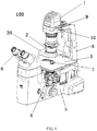
- FIG. 1 shows an exemplary microscope 100 according to the invention, including some common components such as a base 5, an arm 8, a condenser 2, a stage 3, an objective 4, an eyepiece unit 6 and a set of intermediate imaging lenses (not shown).
- the microscope 100 may be, for example, a so-called inverted microscope, wherein a plurality of objectives 4 having different magnifications and mounted on an objective turret are arranged below the stage 3, and the objective turret may be rotated to align a selected objective 4 with an aperture 7 in the stage 3 as needed, in order to observe a specimen (not shown) placed above the aperture 7 on the stage 3.
- the condenser 2 is, for example, cylindrical as a whole and is mounted vertically at a tip end of the arm 8.
- the condenser 2 is configured such that transmitting illumination light (for example, white light) from a transmitting illumination light source 1 (for example, including a light emitting diode, which is generally a white light LED) is collected by the condenser 2 (more specifically, converged by one or more condenser lenses included in the condenser 2), then is irradiated from above the stage 3 to the specimen on the stage, and thereafter enters the objective 4 through the specimen, thereby producing a bright field image to enable bright field observation.
- the transmitting illumination light source 1 is also mounted to the arm 8, but the transmitting illumination light source may be an external light source provided outside the microscope.
- the microscope 100 also has a fluorescence observation function.
- the microscope 100 further includes a fluorescent illumination light source (not shown, generally multi-channel monochromatic LEDs) that can be built inside or outside the base 5 of the microscope.
- a fluorescent illumination light source (not shown, generally multi-channel monochromatic LEDs) that can be built inside or outside the base 5 of the microscope.
- Certain monochromatic illumination light emitted from the fluorescent illumination light source becomes excitation light (for example, ultraviolet light) after passing through an excitation filter, and then is irradiated from below the stage 3 through the objective 4 to the specimen on the stage, thereby exciting the fluorescent substance contained in the specimen to emit fluorescence.
- excitation light for example, ultraviolet light
- the fluorescence After the fluorescence is reflected by the specimen, it travels downward to enter the objective 4, and finally into the eyepiece unit 6 through the set of intermediate imaging lenses. In this way, fluorescence observation is realized and a fluorescent image of the specimen can be observed.
- a light shielding device 20 is mounted between the transmitting illumination light source 1 and the specimen on the stage, e.g. to an lower end portion of the condenser 2 to at least partially block the ambient light that would otherwise enter the objective 4.
- the light shielding device 20 comprises a light shield 21 and a mounting mechanism configured to mount the light shield below the lower end portion of the condenser 2 in a manually removable manner.
- mount ... in a manually removable manner means that the light shield can be easily and quickly attached to and detached from the condenser 2 by hand without using a tool.
- FIGS. 2 to 5 show several exemplary configurations of the mounting mechanism.
- the mounting mechanism includes a collar 22 mounted around the lower end portion of the condenser 2.
- the collar 22 may be in the form of, for example, a circular ring corresponding to the circular cross section of the condenser 2.
- a plurality of threaded holes 26 (e.g. three are illustrated in the figure), which are preferably evenly spaced apart from each other, may be provided circumferentially in the collar 22, and a lock screw 25 is fitted in each of the threaded holes 26.
- each lock screw 25 By screwing the lock screws 25 radially inward into the corresponding threaded holes 26, the tip end of each lock screw 25 is abutted against the outer circumferential surface of the condenser 2, thereby fixing the collar 22 to the lower end portion of the condenser 2.
- the vertical position of the collar 22 may be adjusted by loosening each lock screw 25, then moving the collar 22 upward or downward to a desired new position, and then tightening each lock screw.
- the manner of mounting the collar 22 to the lower end portion of the condenser 2 is not limited to use of the above-mentioned lock screws 25; instead, various ways of connecting, such as adhesive bonding, threaded connection (by providing matching threads on the outer circumferential surface of the condenser 2 and the inner circumferential surface of the collar 22), and form-fit connection (e.g. snap-fit) may be adopted as appropriate.
- the collar 22 may also be configured to be integrally formed with the casing of the condenser 2 at the lower end portion of the condenser 2.
- One or more magnets 27 are fixed to the lower end surface of the collar 22 by e.g. adhesive bonding, and the light shield 21 may be made at least partially by a ferromagnetic material.
- the light shield 21 can be conveniently attached to the collar 22 by the magnetic attractive force with the magnets 27, and can be removed easily and quickly from the collar 22 by only overcoming the magnetic attractive force by hand.
- a bending portion 28 for hand grasping may be provided at the peripheral edge of the light shield 21.
- six magnets 27 are evenly distributed in the circumferential direction, but the invention is obviously not limited to this.
- the number of the magnets 27 may vary depending on the weight of the light shield 21 and the applied force desired to detach the light shield 21.
- a depression 24 may be provided in the upper surface of the light shield 21.
- the height of the light shield 21 or the distance between it and the stage 3 may be set by adjusting the vertical position of the collar 22 on the condenser 2 and/or by adjusting the axial length (i.e. width in vertical direction shown in FIG. 2 ) of the collar 22.
- a desired light shielding effect can be achieved by appropriately setting the height and/or size of the light shield 21 according to the space arrangement requirements in the microscope 100.
- the light shield 21 may be a solid thin plate, but may also be configured as a closed plate including a through hole 23 and a light shielding portion surrounding the through hole 23 as shown in FIG. 2 .
- the through hole 23 is positioned, sized and shaped to allow all or part of the transmitting illumination light from the condenser 2 to pass through the light shield 21.
- the edge of the through hole 23 in the light shield 21 may be arranged e.g. in close proximity to the lower end portion of the condenser 2, no ambient light is allowed to pass downward through the through hole 23, while other ambient light can still be blocked by the light shielding portion surrounding the through hole 23.
- the transmitting illumination light can still be radiated downward from the condenser 2 through the through hole 23 without being blocked by the light shield 21. That is, the microscope can be switched from the fluorescence observation mode using the fluorescent illumination light source to the bright field observation using the transmitting illumination light source 1, without removing the light shield 21, which improves the use convenience of the microscope 100.
- the microscope 100 may be provided with a filter (hereinafter referred to as "illumination light path filter”) in a light path between the transmitting illumination light source and the specimen on the stage.
- illumination light path filter a filter
- an illumination light path filter 9 may be arranged in a light path between the transmitting illumination light source 1 and the condenser 2, as shown in FIG. 1 . More specifically, the illumination light path filter 9 may be disposed e.g. at a light outlet of the transmitting illumination light source 1. The illumination light path filter 9 may be received, for example, in a slider 10 and inserted between the light source 1 and the condenser 2 by way of the slider 10.
- Such an illumination light path filter can selectively reduce transmission ratio of certain spectrum range, and may be any one of a neutral density filter, a color filter, a bandpass filter, a notch filter, a long pass filter, a spectral filter and a multivariate optical element that can tune transmission at different wavelengths.
- the illumination light path filter has different transmissions for light of different wavelengths to match with emission spectral intensity of the transmitting illumination light source.
- Transmission of the illumination light path filter may be inversely proportional to the emission spectral intensity of the transmitting illumination light source. Transmission of the illumination light path filter may be lower for a wavelength with a higher emission spectral intensity, and higher for a wavelength with a lower emission spectral intensity.
- the maximum transmission may be not higher than 2%, while the minimum transmission may be not lower than 1%.
- the illumination light path filter 9 is preferably a neutral density filter.
- the neutral density filter 9 can attenuate light of different wavelengths passing therethrough in the same proportion/ratio, and thus the excitation light radiated upward through the specimen will be attenuated by the neutral density filter 9, so the auto-fluorescence excited by the attenuated excitation light in the LED of the transmitting illumination light source will be reduced.
- the auto-fluorescence will be attenuated again by the neutral density filter 9 when it is irradiated downward. Eventually, little or no auto-fluorescence enters the objective 4, thereby helping to improve the contrast of the fluorescent image.
- the neutral density filter 9 also enables normal use of phase contrast, differential interference contrast (DIC), plastic differential interference contrast (Plas-DIC) and other observation methods of the microscope under transmitting light illumination without user operations (unnecessary to remove the light shield 21), and helps to realize the function of capturing fluorescent and bright field images with one button click as well as the function of switching between fluorescence and bright field observations with one button click.
- DIC differential interference contrast
- Plas-DIC plastic differential interference contrast
- the following optical parameters may be adopted for the illumination light path filter 9 that is preferably a neutral density filter: an average reflection of not more than 4% for light with a wavelength of 420 nm to 680 nm, an average transmission of not more than 2% (corresponding to an optical density of not less than 1.7) for light with a wavelength of 350 nm to 400 nm, and an average transmission between 1.3% and 2% (corresponding to an optical density between 1.7 and 1.9) for light with a wavelength of 400 nm to 700 nm.
- a neutral density filter an average reflection of not more than 4% for light with a wavelength of 420 nm to 680 nm, an average transmission of not more than 2% (corresponding to an optical density of not less than 1.7) for light with a wavelength of 350 nm to 400 nm, and an average transmission between 1.3% and 2% (corresponding to an optical density between 1.7 and 1.9) for light with a wavelength of 400 nm to 700 nm.
- an opaque shield may be used in place of the illumination light path filter 9 to completely block the light path (having the same effect as the case where the light shield 21 is a solid thin plate) in consideration of cost saving etc.
- the opaque shield will block not only the upward excitation light and the downward auto-fluorescence, but also the transmitting illumination light radiated downward. Therefore, it is not possible to realize the function of capturing fluorescent and bright field images with one button click and the function of switching between fluorescence and bright field observations with one button click. If a bright field image produced by using transmitting illumination light is desired, the user needs to push away the slider 10, and in this case the convenience of use will be impaired.
- the mounting mechanism still includes a collar 22 which can be mounted around the lower end portion of the condenser 2 in the same way as the collar 22 shown in FIG. 2 .
- a protrusion 33 is provided on the lower end portion of the collar 22 shown in FIG. 3 .
- the protrusion 33 has, for example, a semicircular shape or a minor arc shape extending in the circumferential direction of the collar 22 and has an L-shaped cross section.
- a slot 34 having a semicircular shape or a minor arc shape as a whole is formed between the two branches of the L shape.
- a circular boss 31 is provided on the upper surface of the light shield 21, and a circular or arc-shaped flange 32 is formed along the circumferential direction of the circular boss 31.
- the flange 32 is configured to be inserted and fitted into the slot 34 in a direction indicated by the blank arrow shown in FIG.
- the light shield 21 can be conveniently mounted to the lower end portion of the collar 22.
- the light shield 21 can be removed easily as long as the flange 32 is simply pulled out of the slot 34 in a reverse direction.
- positions of the slot and the flange may be exchanged, that is, the slot is arranged on the light shield 21 and the flange is arranged on the collar 22.
- the shape of the slot and the flange is not limited to a circular shape or an arc shape, but may be, for example, a linear shape. Naturally, in the case of a linear shape, it is preferable that the slot and the flange are arranged at positions that do not block the hollow portion of the collar 22 or the opening 23 (if provided) of the light shield 21.
- the upper surface of the light shield 21 shown in FIG. 4 is also provided with a circular boss 51, which is formed with a plurality of radially protruding protrusions 52 arranged at intervals in the circumferential direction (in the embodiment of FIG. 4 , three evenly spaced protrusions are provided, but only two of them are shown).
- the lower end portion of the collar 22 shown in FIG. 4 is provided with a plurality of L-shaped grooves in one-to-one correspondence to the plurality of protrusions 52. Specifically, each L-shaped groove is composed of a first portion 53 extending vertically and a second portion 54 extending horizontally.
- each of the protrusions 52 is first aligned with the first portion 53 of a corresponding L-shaped groove, and then the light shield 21 is moved upward so that the protrusion 52 is lifted a sufficient distance in the corresponding first portion 53.
- the light shield 21 is rotated in the direction of the black arrow indicated in FIG. 4 , so that the protrusion 52 is rotated in the horizontal plane into the second portion 54 of the corresponding L-shaped groove, and is thereby supported on a portion of the collar delimiting the second portion 54. It can be seen that a bayonet connection is thus formed between the collar 22 and the circular boss 51.
- the bayonet connection can be easily disengaged by performing the above actions in a reverse order.
- positions of the protrusions 52 and the L-shaped grooves may be exchanged.
- protrusions protruding radially inward may be provided on the inner circumferential surface of the lower end portion of the collar 22, while corresponding L-shaped grooves may be provided on the outer circumferential surface of the circular boss 51.
- two recessed portions 29 facing each other may be provided on the outer peripheral edge of the light shield 21 to facilitate grasping by two fingers of a user hand.
- the mounting mechanism includes at least two clamping members 41 and 42 biased toward each other in e.g. a resilient manner (may be realized by e.g. a tensile spring connected therebetween, not shown) to clamp the lower end portion of the condenser 2.
- the radially inwardly facing surfaces of the clamping members 41, 42 may be designed as arc-shaped surfaces to match and frictionally engage the outer circumferential surface of the condenser 2.
- Grips 43, 44 may be provided on the clamping members 41 and 42, respectively, and both hands may grasp them to pull apart the two clamping members against the spring force. In this way, the clamping members 41 and 42 can clamp the condenser 2 and be removed from it.
- the light shield 21 can be fixed to the lower end surface of one of the at least two clamping members by e.g. adhesive bonding or any other suitable methods, so that it can be mounted and dismounted together with the clamping members.
- the light shield 21 may optionally include the through hole 23 as described above, so that it is unnecessary to remove the light shield 21 from the condenser 2 during bright field observation of the microscope.
- the illumination light path filter 9 arranged in the light path between the transmitting illumination light source 1 and the specimen on the stage is used to favorably attenuate the excitation light and auto-fluorescence passing through the through hole 23.
- another filter 60 (hereinafter referred to as "light shield filter”) may be provided at the through hole 23 of the light shield 21 to close the through hole.
- the effect of the light shield filter 60 is the same as that of the illumination light path filter 9 shown in Fig. 1 .
- the light shield filter 60 may be attached in the through-hole 23 or attached to the edge of the through-hole 23 by, for example, adhesive bonding. Alternatively, as shown in FIG.
- a holder 61 may be provided in the through hole 23, and a depression 63 may be provided in the holder 61 to receive the light shield filter 60.
- the holder 61 may be fixed at the edge of the through-hole 23 through, for example, a plurality of fasteners 62, thereby the light shield filter 60 is indirectly arranged at the through-hole 23.
- the light shield filter 60 may have the same type and optical properties as the illumination light path filter 9 described above (for example, the filters 9 and 60 may be identical neutral density filters).
- the transmitting illumination light radiated downward will also be attenuated by the illumination light path filter 9 and/or light shield filter 60 described above.
- the driving current of e.g. the white light LED in the transmitting illumination light source may be set to maximum the light intensity so as not to impair the bright field effect of the transmitting illumination light source.
- optical parameters of the filter(s) may be set by comprehensively taking account of the energy of the existing light sources and acceptable bright field effect, such that the attenuation by the filter(s) would not adversely affect the bright field effect.
- illumination light path filter 9 and the light shield filter 60 may be provided in the microscope system depending on the specific product design and/or application. It would also be appreciated by those skilled in the art that the terms “illumination light path filter 9" and “light shield filter 60" as used herein are just for the purpose of differentiation between the two filters according to their respective positions in the microscope system, and both of them may be any conventional filter in the field of optical components, such as a neutral density filter, a color filter, a bandpass filter, a notch filter, a long pass filter, a spectral filter or a multivariate optical element that can tune transmission at different wavelengths.
- a simple light shield 21 can be conveniently mounted to the lower end portion of the condenser 2 in the fluorescence observation mode to effectively block ambient light; and when fluorescence observation is not performed, the light shield 21 can be quickly and easily removed manually, which simplifies the structure of the light shielding device and improves the convenience of use.
- the light shield 21 removed from the condenser 2 may be placed, for example, in a recess (not shown) provided on the bottom surface of the base 5 of the microscope 100 in order not to be lost.
- the bending portion 28 provided on the light shield 21 helps to pull the light shield 21 from the recess and mount it onto the condenser 2 again.
Landscapes
- Physics & Mathematics (AREA)
- General Physics & Mathematics (AREA)
- Optics & Photonics (AREA)
- Chemical & Material Sciences (AREA)
- Analytical Chemistry (AREA)
- Microscoopes, Condenser (AREA)
Abstract
Description
- The invention relates to the field of microscope, in particular to a microscope with a fluorescence observation function, and more particularly to a light shielding device used for such a microscope.
- Fluorescence microscopes or microscopes with a fluorescence observation function are known in the art. In this type of microscope, a specimen located on a stage of the microscope is irradiated with excitation light from a specified light source when fluorescence observation is performed. The fluorescent substance contained in the specimen is excited by the excitation light to emit fluorescence having a longer wavelength than that of the excitation light, so a fluorescent image of the specimen can be observed through an objective and others of the microscope.
- However, the fluorescence is weak light, so if ambient light other than the fluorescence emitted by the specimen also enters the objective of the microscope (in particular, it is easier to receive ambient light when the objective is arranged below the stage), it will mix with the fluorescence and interfere with the fluorescent image of the specimen, making it difficult to obtain a clear fluorescent image with sufficient contrast.
- In this regard, it has been proposed in the prior art to equip the microscope with a light shielding device to minimize the ambient light that enters the objective during fluorescence observation of the microscope, so that the contrast of the fluorescent image of the specimen can be improved without needing to operate the microscope in a dark environment. However, the existing light shielding devices still have room for improvement in terms of convenience in use and installation.
- The invention aims to overcome one or more defects and/or other problems existing in the prior art.
- In a first aspect, the invention relates to a light shielding device for a microscope, the microscope comprising a condenser configured so that transmitting illumination light from a transmitting illumination light source is irradiated from above a stage to a specimen on the stage via the condenser; wherein fluorescent illumination light from a fluorescent illumination light source is irradiated from below the stage to the specimen on the stage; wherein the light shielding device is mounted to a lower end portion of the condenser to at least partially block ambient light entering an objective of the microscope, and wherein the light shielding device comprises a light shield and a mounting mechanism configured to mount the light shield below the lower end portion of the condenser in a manually removable manner.
- According to an exemplary configuration of the first aspect, the mounting mechanism comprises a collar mounted around or integrally formed with the lower end portion of the condenser, one or more magnets are fixed on a lower end surface of the collar, and the light shield contains a ferromagnetic material and is attached to the collar by a magnetic attractive force between the magnet(s) and the ferromagnetic material.
- According to an exemplary configuration of the first aspect, a depression is provided in an upper surface of the light shield, and when the light shield is attached to the collar, a lower end portion of the collar is received in the depression to define a position of the light shield relative to the collar.
- According to an exemplary configuration of the first aspect, the mounting mechanism comprises a collar mounted around or integrally formed with the lower end portion of the condenser, one of a lower end portion of the collar and an upper surface of the light shield is provided with a slot, and the other of the lower end portion of the collar and the upper surface of the light shield is provided with a flange fitted in the slot.
- According to an exemplary configuration of the first aspect, the mounting mechanism comprises a collar mounted around or integrally formed with the lower end portion of the condenser, a circular boss is provided on an upper surface of the light shield, one of a lower end portion of the collar and the circular boss is formed with a plurality of radially protruding protrusions arranged circumferentially at intervals, and the other of the lower end portion of the collar and the circular boss is formed with a plurality of L-shaped grooves corresponding to the plurality of protrusions, wherein the plurality of protrusions are respectively received in the plurality of L-shaped grooves to form a bayonet connection between the collar and the circular boss.
- According to an exemplary configuration of the first aspect, the mounting mechanism comprises at least two clamping members resiliently biased toward each other to clamp the lower end portion of the condenser, and the light shield is fixed to a lower end surface of one of the at least two clamping members.
- According to an exemplary configuration of the first aspect, the light shield is a solid plate, or a closed plate with a through hole.
- According to an exemplary configuration of the first aspect, the light shield comprises a through hole and a light shielding portion surrounding the through hole, the through hole being configured to allow all or part of the transmitting illumination light from the condenser to pass through the light shield.
- According to an exemplary configuration of the first aspect, a light shield filter is provided at the through hole.
- According to an exemplary configuration of the first aspect, the light shield filter is any one of a neutral density filter, a color filter, a bandpass filter, a notch filter, a long pass filter, a spectral filter and a multivariate optical element that can tune transmission at different wavelengths.
- According to an exemplary configuration of the first aspect, the light shield filter has different transmissions for light of different wavelengths to match with emission spectral intensity of the transmitting illumination light source; transmission of the light shield filter is inversely proportional to the emission spectral intensity of the transmitting illumination light source; transmission of the light shield filter is lower for a wavelength with a higher emission spectral intensity, and is higher for a wavelength with a lower emission spectral intensity.
- According to an exemplary configuration of the first aspect, the light shield filter has an average reflection of not more than 4% for light with a wavelength of 420 nm to 680 nm, an average transmission of not more than 2% for light with a wavelength of 350 nm to 400 nm, and an average transmission between 1.3% and 2% for light with a wavelength of 400 nm to 700 nm.
- In a second aspect, the invention relates to a microscope, comprising: a condenser configured so that transmitting illumination light from a transmitting illumination light source is irradiated from above a stage to a specimen on the stage via the condenser, wherein fluorescent illumination light from a fluorescent illumination light source is irradiated from below the stage to the specimen on the stage; and a light shielding device according to the first aspect.
- According to an exemplary configuration of the second aspect, a recess is provided on a bottom surface of a base of the microscope to receive the light shield removed from the condenser.
- According to an exemplary configuration of the second aspect, the microscope further comprises an illumination light path filter disposed in a light path between the transmitting illumination light source and the specimen on the stage.
- According to an exemplary configuration of the second aspect, the illumination light path filter is disposed at a light outlet of the transmitting illumination light source.
- According to an exemplary configuration of the second aspect, the illumination light path filter is any one of a neutral density filter, a color filter, a bandpass filter, a notch filter, a long pass filter, a spectral filter and a multivariate optical element that can tune transmission at different wavelengths.
- According to an exemplary configuration of the second aspect, the illumination light path filter has different transmissions for light of different wavelengths to match with emission spectral intensity of the transmitting illumination light source; transmission of the illumination light path filter is inversely proportional to the emission spectral intensity of the transmitting illumination light source; transmission of the illumination light path filter is lower for a wavelength with a higher emission spectral intensity, and is higher for a wavelength with a lower emission spectral intensity.
- According to an exemplary configuration of the second aspect, the illumination light path filter has an average reflection of not more than 4% for light with a wavelength of 420 nm to 680 nm, an average transmission of not more than 2% for light with a wavelength of 350 nm to 400 nm, and an average transmission between 1.3% and 2% for light with a wavelength of 400 nm to 700 nm.
- In a third aspect, the invention relates to a light shielding device for a microscope in which transmitting illumination light from a transmitting illumination light source is irradiated from above a stage to a specimen on the stage and fluorescent illumination light from a fluorescent illumination light source is irradiated from below the stage to the specimen on the stage; wherein the light shielding device comprises a light shield disposed above the specimen on the stage to at least partially block ambient light entering an objective of the microscope, and wherein the light shield comprises a through hole and a light shielding portion surrounding the through hole, the through hole being configured to allow all or part of the transmitting illumination light to pass through the light shield, and a light shield filter is provided at the through hole.
- According to one or more exemplary configurations of the third aspect, the light shield filter may have the same features as the light shield filter according to the first aspect as describe above.
- According to an exemplary configuration of the third aspect, the microscope comprises a condenser configured so that the transmitting illumination light from the transmitting illumination light source is irradiated from above the stage to the specimen on the stage via the condenser, the light shielding device is mounted to a lower end portion of the condenser and further comprises a mounting mechanism configured to mount the light shield below the lower end portion of the condenser in a manually removable manner.
- According to one or more exemplary configurations of the third aspect, the mounting mechanism may have the same features as the mounting mechanism according to the first aspect as describe above.
- In a fourth aspect, the invention relates to a microscope, in which transmitting illumination light from a transmitting illumination light source is irradiated from above a stage to a specimen on the stage and fluorescent illumination light from a fluorescent illumination light source is irradiated from below the stage to the specimen on the stage, and which comprises a light shielding device according to the third aspect.
- According to an exemplary configuration of the fourth aspect, a recess is provided on a bottom surface of a base of the microscope to receive the light shield removed from above the specimen on the stage.
- In a fifth aspect, the invention relates to a microscope, in which transmitting illumination light from a transmitting illumination light source is irradiated from above a stage to a specimen on the stage and fluorescent illumination light from a fluorescent illumination light source is irradiated from below the stage to the specimen on the stage, and which comprises: a light shielding device disposed above and the specimen on the stage to at least partially block ambient light entering an objective of the microscope; and an illumination light path filter disposed in a light path between the transmitting illumination light source and the specimen on the stage.
- According to one or more exemplary configurations of the fifth aspect, the illumination light path filter may have the same features as the illumination light path filter according to the second aspect as describe above.
- According to an exemplary configuration of the fifth aspect, the microscope further comprises a condenser configured so that the transmitting illumination light from the transmitting illumination light source is irradiated from above the stage to the specimen on the stage via the condenser, the light shielding device is mounted to a lower end portion of the condenser and comprises a light shield and a mounting mechanism configured to mount the light shield below the lower end portion of the condenser in a manually removable manner.
- According to one or more exemplary configurations of the fifth aspect, the mounting mechanism may have the same features as the mounting mechanism according to the first aspect as describe above.
- According to an exemplary configuration of the fifth aspect, the light shield comprises a through hole and a light shielding portion surrounding the through hole, the through hole being configured to allow all or part of the transmitting illumination light from the condenser to pass through the light shield.
- According to an exemplary configuration of the fifth aspect, a recess is provided on a bottom surface of a base of the microscope to receive the light shield removed from the condenser.
- The light shielding device for a microscope according to the invention may be mounted to e.g. a lower end portion of the condenser of the microscope to at least partially block ambient light entering the objective, and the light shielding device comprises a light shield and a mounting mechanism configured to mount the light shield below the lower end portion of the condenser in a manually removable manner. In this way, when the microscope is used for fluorescence observation, the light shield featuring a simple structure and easy installation can effectively block the ambient light that would otherwise enter the objective of the microscope, thereby ensuring the contrast and definition of the fluorescent image of the microscope. Moreover, when the microscope is not used for fluorescence observation, the light shield can be quickly and easily removed so as not to hinder other operations (e.g. bright-field observation performed using a transmitting illumination light source) of the microscope. This simplifies the structure of the light shielding device and improves its convenience of use. In addition, according to the invention, a filter, in particular a neutral density filter, may be provided between the transmitting illumination light source and the specimen on the stage of the microscope and/or provided at the light shield. This can not only effectively prevent various ambient light from interfering with the fluorescent image, but also achieve other observation operations and functions of the microscope even without removing the light shield, which greatly improves the practicality and functionality of the microscope.
- The above and other advantages, features, and details of the invention can be derived from the exemplary embodiments described below with reference to the drawings, in which:
-
FIG. 1 is a perspective view of an exemplary configuration of a microscope according to the invention. -
FIG. 2 shows a first embodiment of the light shielding device for a microscope according to the invention. -
FIG. 3 shows a second embodiment of the light shielding device for a microscope according to the invention. -
FIG. 4 shows a third embodiment of the light shielding device for a microscope according to the invention. -
FIG. 5 shows a fourth embodiment of the light shielding device for a microscope according to the invention. -
FIG. 6 shows a fifth embodiment of the light shielding device for a microscope according to the invention. -
FIG. 7 is a perspective view of another exemplary configuration of a microscope according to the invention. -
FIG. 1 shows anexemplary microscope 100 according to the invention, including some common components such as abase 5, anarm 8, acondenser 2, astage 3, an objective 4, aneyepiece unit 6 and a set of intermediate imaging lenses (not shown). Themicroscope 100 may be, for example, a so-called inverted microscope, wherein a plurality ofobjectives 4 having different magnifications and mounted on an objective turret are arranged below thestage 3, and the objective turret may be rotated to align a selectedobjective 4 with anaperture 7 in thestage 3 as needed, in order to observe a specimen (not shown) placed above theaperture 7 on thestage 3. Thecondenser 2 is, for example, cylindrical as a whole and is mounted vertically at a tip end of thearm 8. Thecondenser 2 is configured such that transmitting illumination light (for example, white light) from a transmitting illumination light source 1 (for example, including a light emitting diode, which is generally a white light LED) is collected by the condenser 2 (more specifically, converged by one or more condenser lenses included in the condenser 2), then is irradiated from above thestage 3 to the specimen on the stage, and thereafter enters theobjective 4 through the specimen, thereby producing a bright field image to enable bright field observation. In the illustrated embodiment, the transmittingillumination light source 1 is also mounted to thearm 8, but the transmitting illumination light source may be an external light source provided outside the microscope. Themicroscope 100 also has a fluorescence observation function. To this end, themicroscope 100 further includes a fluorescent illumination light source (not shown, generally multi-channel monochromatic LEDs) that can be built inside or outside thebase 5 of the microscope. Certain monochromatic illumination light emitted from the fluorescent illumination light source becomes excitation light (for example, ultraviolet light) after passing through an excitation filter, and then is irradiated from below thestage 3 through theobjective 4 to the specimen on the stage, thereby exciting the fluorescent substance contained in the specimen to emit fluorescence. After the fluorescence is reflected by the specimen, it travels downward to enter theobjective 4, and finally into theeyepiece unit 6 through the set of intermediate imaging lenses. In this way, fluorescence observation is realized and a fluorescent image of the specimen can be observed. - In the fluorescence observation mode of the
microscope 100, in order to prevent ambient light from entering theobjective 4 and mixing with the fluorescence emitted from the specimen to reduce the contrast of the fluorescent image, alight shielding device 20 is mounted between the transmittingillumination light source 1 and the specimen on the stage, e.g. to an lower end portion of thecondenser 2 to at least partially block the ambient light that would otherwise enter theobjective 4. Thus fluorescence observation can be performed with themicroscope 100 even if it is not in a dark environment. - According to an embodiment of the invention, the
light shielding device 20 comprises alight shield 21 and a mounting mechanism configured to mount the light shield below the lower end portion of thecondenser 2 in a manually removable manner. Herein, "mount ... in a manually removable manner" means that the light shield can be easily and quickly attached to and detached from thecondenser 2 by hand without using a tool.FIGS. 2 to 5 show several exemplary configurations of the mounting mechanism. - In the embodiment shown in
FIG. 2 , the mounting mechanism includes acollar 22 mounted around the lower end portion of thecondenser 2. To this end, thecollar 22 may be in the form of, for example, a circular ring corresponding to the circular cross section of thecondenser 2. A plurality of threaded holes 26 (e.g. three are illustrated in the figure), which are preferably evenly spaced apart from each other, may be provided circumferentially in thecollar 22, and alock screw 25 is fitted in each of the threaded holes 26. By screwing the lock screws 25 radially inward into the corresponding threadedholes 26, the tip end of eachlock screw 25 is abutted against the outer circumferential surface of thecondenser 2, thereby fixing thecollar 22 to the lower end portion of thecondenser 2. The vertical position of thecollar 22 may be adjusted by loosening eachlock screw 25, then moving thecollar 22 upward or downward to a desired new position, and then tightening each lock screw. It may be understood by those skilled in the art that the manner of mounting thecollar 22 to the lower end portion of thecondenser 2 is not limited to use of the above-mentioned lock screws 25; instead, various ways of connecting, such as adhesive bonding, threaded connection (by providing matching threads on the outer circumferential surface of thecondenser 2 and the inner circumferential surface of the collar 22), and form-fit connection (e.g. snap-fit) may be adopted as appropriate. Thecollar 22 may also be configured to be integrally formed with the casing of thecondenser 2 at the lower end portion of thecondenser 2. - One or
more magnets 27 are fixed to the lower end surface of thecollar 22 by e.g. adhesive bonding, and thelight shield 21 may be made at least partially by a ferromagnetic material. Thus, thelight shield 21 can be conveniently attached to thecollar 22 by the magnetic attractive force with themagnets 27, and can be removed easily and quickly from thecollar 22 by only overcoming the magnetic attractive force by hand. In order to facilitate the disassembly and assembly of thelight shield 21 by hand. A bendingportion 28 for hand grasping may be provided at the peripheral edge of thelight shield 21. In the illustrated embodiment, sixmagnets 27 are evenly distributed in the circumferential direction, but the invention is obviously not limited to this. The number of themagnets 27 may vary depending on the weight of thelight shield 21 and the applied force desired to detach thelight shield 21. In addition, in order to quickly and accurately mount thelight shield 21 in place to achieve a good light shielding effect, adepression 24 may be provided in the upper surface of thelight shield 21. When thelight shield 21 is attached to thecollar 22, the lower end portion of thecollar 22 is received in thedepression 24 in such a manner that thedepression 24 can define the position of thelight shield 21 relative to thecollar 22 through the engagement between the inner side wall of thedepression 24 and the outer circumferential wall of the lower end portion of thecollar 22. - The height of the
light shield 21 or the distance between it and thestage 3 may be set by adjusting the vertical position of thecollar 22 on thecondenser 2 and/or by adjusting the axial length (i.e. width in vertical direction shown inFIG. 2 ) of thecollar 22. A desired light shielding effect can be achieved by appropriately setting the height and/or size of thelight shield 21 according to the space arrangement requirements in themicroscope 100. Thelight shield 21 may be a solid thin plate, but may also be configured as a closed plate including a throughhole 23 and a light shielding portion surrounding the throughhole 23 as shown inFIG. 2 . The throughhole 23 is positioned, sized and shaped to allow all or part of the transmitting illumination light from thecondenser 2 to pass through thelight shield 21. During fluorescence observation, since the edge of the throughhole 23 in thelight shield 21 may be arranged e.g. in close proximity to the lower end portion of thecondenser 2, no ambient light is allowed to pass downward through the throughhole 23, while other ambient light can still be blocked by the light shielding portion surrounding the throughhole 23. When it is switched from the fluorescence observation mode to the bright field observation mode performed using the transmittingillumination light source 1, the transmitting illumination light can still be radiated downward from thecondenser 2 through the throughhole 23 without being blocked by thelight shield 21. That is, the microscope can be switched from the fluorescence observation mode using the fluorescent illumination light source to the bright field observation using the transmittingillumination light source 1, without removing thelight shield 21, which improves the use convenience of themicroscope 100. - In the case where the
light shield 21 is provided with the throughhole 23, during fluorescence observation, the excitation light that is irradiated upward to the specimen on the stage through theobjective 4 will pass through the normally translucent specimen and continue to travel upward to the LED fluorescent powder in the transmitting illumination light source, which will be excited to generate auto-fluorescence. The auto-fluorescence can be irradiated downward and enter theobjective 4, thereby disturbing the fluorescent image of the specimen. In order to reduce the adverse effect of the auto-fluorescence, themicroscope 100 according to the invention may be provided with a filter (hereinafter referred to as "illumination light path filter") in a light path between the transmitting illumination light source and the specimen on the stage. For example, an illumination light path filter 9 may be arranged in a light path between the transmittingillumination light source 1 and thecondenser 2, as shown inFIG. 1 . More specifically, the illumination light path filter 9 may be disposed e.g. at a light outlet of the transmittingillumination light source 1. The illumination light path filter 9 may be received, for example, in aslider 10 and inserted between thelight source 1 and thecondenser 2 by way of theslider 10. - Such an illumination light path filter can selectively reduce transmission ratio of certain spectrum range, and may be any one of a neutral density filter, a color filter, a bandpass filter, a notch filter, a long pass filter, a spectral filter and a multivariate optical element that can tune transmission at different wavelengths.
- Preferably, the illumination light path filter has different transmissions for light of different wavelengths to match with emission spectral intensity of the transmitting illumination light source. Transmission of the illumination light path filter may be inversely proportional to the emission spectral intensity of the transmitting illumination light source. Transmission of the illumination light path filter may be lower for a wavelength with a higher emission spectral intensity, and higher for a wavelength with a lower emission spectral intensity. The maximum transmission may be not higher than 2%, while the minimum transmission may be not lower than 1%.
- In view of the fact that visual observation requires light of different wavelengths is tuned at the same ratio after passing through the filter in order to avoid color cast, the illumination light path filter 9 is preferably a neutral density filter. The
neutral density filter 9 can attenuate light of different wavelengths passing therethrough in the same proportion/ratio, and thus the excitation light radiated upward through the specimen will be attenuated by theneutral density filter 9, so the auto-fluorescence excited by the attenuated excitation light in the LED of the transmitting illumination light source will be reduced. The auto-fluorescence will be attenuated again by theneutral density filter 9 when it is irradiated downward. Eventually, little or no auto-fluorescence enters theobjective 4, thereby helping to improve the contrast of the fluorescent image. In addition to this advantage, theneutral density filter 9 also enables normal use of phase contrast, differential interference contrast (DIC), plastic differential interference contrast (Plas-DIC) and other observation methods of the microscope under transmitting light illumination without user operations (unnecessary to remove the light shield 21), and helps to realize the function of capturing fluorescent and bright field images with one button click as well as the function of switching between fluorescence and bright field observations with one button click. - As an example, the following optical parameters may be adopted for the illumination light path filter 9 that is preferably a neutral density filter: an average reflection of not more than 4% for light with a wavelength of 420 nm to 680 nm, an average transmission of not more than 2% (corresponding to an optical density of not less than 1.7) for light with a wavelength of 350 nm to 400 nm, and an average transmission between 1.3% and 2% (corresponding to an optical density between 1.7 and 1.9) for light with a wavelength of 400 nm to 700 nm.
- It is also conceivable for those skilled in the art that an opaque shield may be used in place of the illumination light path filter 9 to completely block the light path (having the same effect as the case where the
light shield 21 is a solid thin plate) in consideration of cost saving etc. However, the opaque shield will block not only the upward excitation light and the downward auto-fluorescence, but also the transmitting illumination light radiated downward. Therefore, it is not possible to realize the function of capturing fluorescent and bright field images with one button click and the function of switching between fluorescence and bright field observations with one button click. If a bright field image produced by using transmitting illumination light is desired, the user needs to push away theslider 10, and in this case the convenience of use will be impaired. - In the embodiments shown in
FIGS. 3 and4 , the mounting mechanism still includes acollar 22 which can be mounted around the lower end portion of thecondenser 2 in the same way as thecollar 22 shown inFIG. 2 . - However, a
protrusion 33 is provided on the lower end portion of thecollar 22 shown inFIG. 3 . Theprotrusion 33 has, for example, a semicircular shape or a minor arc shape extending in the circumferential direction of thecollar 22 and has an L-shaped cross section. In this way, aslot 34 having a semicircular shape or a minor arc shape as a whole is formed between the two branches of the L shape. Correspondingly, acircular boss 31 is provided on the upper surface of thelight shield 21, and a circular or arc-shapedflange 32 is formed along the circumferential direction of thecircular boss 31. Theflange 32 is configured to be inserted and fitted into theslot 34 in a direction indicated by the blank arrow shown inFIG. 3 , and thereby thelight shield 21 can be conveniently mounted to the lower end portion of thecollar 22. Thelight shield 21 can be removed easily as long as theflange 32 is simply pulled out of theslot 34 in a reverse direction. Those skilled in the art can easily understand that positions of the slot and the flange may be exchanged, that is, the slot is arranged on thelight shield 21 and the flange is arranged on thecollar 22. In addition, the shape of the slot and the flange is not limited to a circular shape or an arc shape, but may be, for example, a linear shape. Naturally, in the case of a linear shape, it is preferable that the slot and the flange are arranged at positions that do not block the hollow portion of thecollar 22 or the opening 23 (if provided) of thelight shield 21. - The upper surface of the
light shield 21 shown inFIG. 4 is also provided with acircular boss 51, which is formed with a plurality of radially protrudingprotrusions 52 arranged at intervals in the circumferential direction (in the embodiment ofFIG. 4 , three evenly spaced protrusions are provided, but only two of them are shown). The lower end portion of thecollar 22 shown inFIG. 4 is provided with a plurality of L-shaped grooves in one-to-one correspondence to the plurality ofprotrusions 52. Specifically, each L-shaped groove is composed of afirst portion 53 extending vertically and asecond portion 54 extending horizontally. When thelight shield 21 is mounted to thecollar 22, each of theprotrusions 52 is first aligned with thefirst portion 53 of a corresponding L-shaped groove, and then thelight shield 21 is moved upward so that theprotrusion 52 is lifted a sufficient distance in the correspondingfirst portion 53. Next, thelight shield 21 is rotated in the direction of the black arrow indicated inFIG. 4 , so that theprotrusion 52 is rotated in the horizontal plane into thesecond portion 54 of the corresponding L-shaped groove, and is thereby supported on a portion of the collar delimiting thesecond portion 54. It can be seen that a bayonet connection is thus formed between thecollar 22 and thecircular boss 51. Those skilled in the art can readily understand that the bayonet connection can be easily disengaged by performing the above actions in a reverse order. In addition, positions of theprotrusions 52 and the L-shaped grooves may be exchanged. For example, protrusions protruding radially inward may be provided on the inner circumferential surface of the lower end portion of thecollar 22, while corresponding L-shaped grooves may be provided on the outer circumferential surface of thecircular boss 51. In order to facilitate disassembly, two recessedportions 29 facing each other may be provided on the outer peripheral edge of thelight shield 21 to facilitate grasping by two fingers of a user hand. - In the embodiment shown in
FIG. 5 , the mounting mechanism includes at least two clampingmembers condenser 2. To this end, the radially inwardly facing surfaces of the clampingmembers condenser 2.Grips members members condenser 2 and be removed from it. Thelight shield 21 can be fixed to the lower end surface of one of the at least two clamping members by e.g. adhesive bonding or any other suitable methods, so that it can be mounted and dismounted together with the clamping members. - In the embodiments shown in
FIGS. 3 to 5 , thelight shield 21 may optionally include the throughhole 23 as described above, so that it is unnecessary to remove thelight shield 21 from thecondenser 2 during bright field observation of the microscope. - It has been described above that the illumination light path filter 9 arranged in the light path between the transmitting
illumination light source 1 and the specimen on the stage is used to favorably attenuate the excitation light and auto-fluorescence passing through the throughhole 23. As an alternative or additional component to the illuminationlight path filter 9, as shown inFIG. 6 , another filter 60 (hereinafter referred to as "light shield filter") may be provided at the throughhole 23 of thelight shield 21 to close the through hole. The effect of thelight shield filter 60 is the same as that of the illumination light path filter 9 shown inFig. 1 . Thelight shield filter 60 may be attached in the through-hole 23 or attached to the edge of the through-hole 23 by, for example, adhesive bonding. Alternatively, as shown inFIG. 6 , aholder 61 may be provided in the throughhole 23, and adepression 63 may be provided in theholder 61 to receive thelight shield filter 60. Theholder 61 may be fixed at the edge of the through-hole 23 through, for example, a plurality offasteners 62, thereby thelight shield filter 60 is indirectly arranged at the through-hole 23. Thelight shield filter 60 may have the same type and optical properties as the illumination light path filter 9 described above (for example, thefilters - During transmitting illumination, the transmitting illumination light radiated downward will also be attenuated by the illumination
light path filter 9 and/orlight shield filter 60 described above. For this, the driving current of e.g. the white light LED in the transmitting illumination light source may be set to maximum the light intensity so as not to impair the bright field effect of the transmitting illumination light source. Besides, optical parameters of the filter(s) may be set by comprehensively taking account of the energy of the existing light sources and acceptable bright field effect, such that the attenuation by the filter(s) would not adversely affect the bright field effect. - A person skilled in the art can appreciate that either or both of the illumination
light path filter 9 and thelight shield filter 60 may be provided in the microscope system depending on the specific product design and/or application. It would also be appreciated by those skilled in the art that the terms "illumination light path filter 9" and "light shield filter 60" as used herein are just for the purpose of differentiation between the two filters according to their respective positions in the microscope system, and both of them may be any conventional filter in the field of optical components, such as a neutral density filter, a color filter, a bandpass filter, a notch filter, a long pass filter, a spectral filter or a multivariate optical element that can tune transmission at different wavelengths. - According to the configurations of the
light shielding devices 20 shown inFIGS. 2 to 5 , a simplelight shield 21 can be conveniently mounted to the lower end portion of thecondenser 2 in the fluorescence observation mode to effectively block ambient light; and when fluorescence observation is not performed, thelight shield 21 can be quickly and easily removed manually, which simplifies the structure of the light shielding device and improves the convenience of use. As shown inFIG. 7 , thelight shield 21 removed from thecondenser 2 may be placed, for example, in a recess (not shown) provided on the bottom surface of thebase 5 of themicroscope 100 in order not to be lost. The bendingportion 28 provided on thelight shield 21 helps to pull thelight shield 21 from the recess and mount it onto thecondenser 2 again. - The embodiments disclosed above are merely examples of the invention, and all obvious modifications and variations made by those skilled in the art should be considered as falling within the scope of the invention.
Claims (26)
- A light shielding device (20) for a microscope (100), the microscope comprising a condenser (2) configured so that transmitting illumination light from a transmitting illumination light source (1) is irradiated from above a stage (3) to a specimen on the stage via the condenser (2),
wherein fluorescent illumination light from a fluorescent illumination light source is irradiated from below the stage (3) to the specimen on the stage,
wherein the light shielding device (20) is mounted to a lower end portion of the condenser (2) to at least partially block ambient light entering an objective (4) of the microscope, and
wherein the light shielding device (20) comprises a light shield (21) and a mounting mechanism configured to mount the light shield below the lower end portion of the condenser (2) in a manually removable manner. - The light shielding device (20) according to claim 1, characterized in that
the mounting mechanism comprises a collar (22) mounted around or integrally formed with the lower end portion of the condenser (2), one or more magnets (27) are fixed on a lower end surface of the collar, and the light shield (21) contains a ferromagnetic material and is attached to the collar (22) by a magnetic attractive force between the magnet(s) (27) and the ferromagnetic material. - The light shielding device (20) according to claim 2, characterized in that
a depression (24) is provided in an upper surface of the light shield (21), and when the light shield is attached to the collar (22), a lower end portion of the collar is received in the depression (24) to define a position of the light shield (21) relative to the collar (22). - The light shielding device (20) according to claim 1, characterized in that- the mounting mechanism comprises a collar (22) mounted around or integrally formed with the lower end portion of the condenser (2), one of a lower end portion of the collar and an upper surface of the light shield (21) is provided with a slot (34), and the other of the lower end portion of the collar and the upper surface of the light shield is provided with a flange (32) fitted in the slot, or- the mounting mechanism comprises a collar (22) mounted around or integrally formed with the lower end portion of the condenser (2), a circular boss (51) is provided on an upper surface of the light shield (21), one of a lower end portion of the collar and the circular boss is formed with a plurality of radially protruding protrusions (52) arranged circumferentially at intervals, and the other of the lower end portion of the collar and the circular boss is formed with a plurality of L-shaped grooves (53, 54) corresponding to the plurality of protrusions (52), wherein the plurality of protrusions are respectively received in the plurality of L-shaped grooves to form a bayonet connection between the collar (22) and the circular boss (51), or- the mounting mechanism comprises at least two clamping members (41, 42) resiliently biased toward each other to clamp the lower end portion of the condenser (2), and the light shield (21) is fixed to a lower end surface of one of the at least two clamping members (41, 42).
- The light shielding device (20) according to any of claims 1-4, characterized in that
the light shield (21) comprises a through hole (23) and a light shielding portion surrounding the through hole, the through hole (23) being configured to allow all or part of the transmitting illumination light from the condenser (2) to pass through the light shield (21). - The light shielding device (20) according to claim 5, characterized in that a light shield filter (60) is provided at the through hole (23).
- The light shielding device (20) according to claim 6, characterized in that- the light shield filter (60) is any one of a neutral density filter, a color filter, a bandpass filter, a notch filter, a long pass filter, a spectral filter and a multivariate optical element that can tune transmission at different wavelengths, or- the light shield filter (60) has different transmissions for light of different wavelengths to match with emission spectral intensity of the transmitting illumination light source; transmission of the light shield filter is inversely proportional to the emission spectral intensity of the transmitting illumination light source; transmission of the light shield filter is lower for a wavelength with a higher emission spectral intensity, and is higher for a wavelength with a lower emission spectral intensity, or- the light shield filter (60) has an average reflection of not more than 4% for light with a wavelength of 420 nm to 680 nm, an average transmission of not more than 2% for light with a wavelength of 350 nm to 400 nm, and an average transmission between 1.3% and 2% for light with a wavelength of 400 nm to 700 nm.
- A microscope (100), comprising:a condenser (2) configured so that transmitting illumination light from a transmitting illumination light source (1) is irradiated from above a stage (3) to a specimen on the stage via the condenser (2), wherein fluorescent illumination light from a fluorescent illumination light source is irradiated from below the stage (3) to the specimen on the stage; anda light shielding device (20) according to any of claims 1-7.
- The microscope (100) according to claim 8, characterized in that
a recess is provided on a bottom surface of a base (5) of the microscope to receive the light shield (21) removed from the condenser (2). - The microscope (100) according to claim 8 or 9, characterized in that
the microscope further comprises an illumination light path filter (9) disposed in a light path between the transmitting illumination light source (1) and the specimen on the stage. - The microscope (100) according to claim 10, characterized in that- the illumination light path filter (9) is disposed at a light outlet of the transmitting illumination light source (1), or- the illumination light path filter (9) is any one of a neutral density filter, a color filter, a bandpass filter, a notch filter, a long pass filter, a spectral filter and a multivariate optical element that can tune transmission at different wavelengths, or- the illumination light path filter (9) has different transmissions for light of different wavelengths to match with emission spectral intensity of the transmitting illumination light source; transmission of the illumination light path filter is inversely proportional to the emission spectral intensity of the transmitting illumination light source; transmission of the illumination light path filter is lower for a wavelength with a higher emission spectral intensity, and is higher for a wavelength with a lower emission spectral intensity, or- the illumination light path filter (9) has an average reflection of not more than 4% for light with a wavelength of 420 nm to 680 nm, an average transmission of not more than 2% for light with a wavelength of 350 nm to 400 nm, and an average transmission between 1.3% and 2% for light with a wavelength of 400 nm to 700 nm.
- A light shielding device (20) for a microscope (100) in which transmitting illumination light from a transmitting illumination light source (1) is irradiated from above a stage (3) to a specimen on the stage and fluorescent illumination light from a fluorescent illumination light source is irradiated from below the stage (3) to the specimen on the stage,
wherein the light shielding device (20) comprises a light shield (21) disposed above the specimen on the stage to at least partially block ambient light entering an objective (4) of the microscope, and
wherein the light shield (21) comprises a through hole (23) and a light shielding portion surrounding the through hole, the through hole (23) being configured to allow all or part of the transmitting illumination light to pass through the light shield (21), and a light shield filter (60) is provided at the through hole (23). - The light shielding device (20) according to claim 12, characterized in that- the light shield filter (60) is any one of a neutral density filter, a color filter, a bandpass filter, a notch filter, a long pass filter, a spectral filter and a multivariate optical element that can tune transmission at different wavelengths, or- the light shield filter (60) has different transmissions for light of different wavelengths to match with emission spectral intensity of the transmitting illumination light source; transmission of the light shield filter is inversely proportional to the emission spectral intensity of the transmitting illumination light source; transmission of the light shield filter is lower for a wavelength with a higher emission spectral intensity, and is higher for a wavelength with a lower emission spectral intensity, or- the light shield filter (60) has an average reflection of not more than 4% for light with a wavelength of 420 nm to 680 nm, an average transmission of not more than 2% for light with a wavelength of 350 nm to 400 nm, and an average transmission between 1.3% and 2% for light with a wavelength of 400 nm to 700 nm.
- The light shielding device (20) according to any of claims 12-13, characterized in that
the microscope comprises a condenser (2) configured so that the transmitting illumination light from the transmitting illumination light source (1) is irradiated from above the stage (3) to the specimen on the stage via the condenser (2), the light shielding device (20) is mounted to a lower end portion of the condenser (2) and further comprises a mounting mechanism configured to mount the light shield (21) below the lower end portion of the condenser (2) in a manually removable manner. - The light shielding device (20) according to claim 14, characterized in that the mounting mechanism comprises a collar (22) mounted around or integrally formed with the lower end portion of the condenser (2), one or more magnets (27) are fixed on a lower end surface of the collar, and the light shield (21) contains a ferromagnetic material and is attached to the collar (22) by a magnetic attractive force between the magnet(s) (27) and the ferromagnetic material.
- The light shielding device (20) according to claim 15, characterized in that
a depression (24) is provided in an upper surface of the light shield (21), and when the light shield is attached to the collar (22), a lower end portion of the collar is received in the depression (24) to define a position of the light shield (21) relative to the collar (22). - The light shielding device (20) according to claim 14, characterized in that- the mounting mechanism comprises a collar (22) mounted around or integrally formed with the lower end portion of the condenser (2), one of a lower end portion of the collar and an upper surface of the light shield (21) is provided with a slot (34), and the other of the lower end portion of the collar and the upper surface of the light shield is provided with a flange (32) fitted in the slot, or- the mounting mechanism comprises a collar (22) mounted around or integrally formed with the lower end portion of the condenser (2), a circular boss (51) is provided on an upper surface of the light shield (21), one of a lower end portion of the collar and the circular boss is formed with a plurality of radially protruding protrusions (52) arranged circumferentially at intervals, and the other of the lower end portion of the collar and the circular boss is formed with a plurality of L-shaped grooves (53, 54) corresponding to the plurality of protrusions (52), wherein the plurality of protrusions are respectively received in the plurality of L-shaped grooves to form a bayonet connection between the collar (22) and the circular boss (51), or- the mounting mechanism comprises at least two clamping members (41, 42) resiliently biased toward each other to clamp the lower end portion of the condenser (2), and the light shield (21) is fixed to a lower end surface of one of the at least two clamping members (41, 42).
- A microscope (100), in which transmitting illumination light from a transmitting illumination light source (1) is irradiated from above a stage (3) to a specimen on the stage and fluorescent illumination light from a fluorescent illumination light source is irradiated from below the stage (3) to the specimen on the stage, and which comprises a light shielding device (20) according to any of claims 12-17.
- The microscope (100) according to claim 18, characterized in that
a recess is provided on a bottom surface of a base (5) of the microscope to receive the light shield (21) removed from above the specimen on the stage. - A microscope (100), in which transmitting illumination light from a transmitting illumination light source (1) is irradiated from above a stage (3) to a specimen on the stage and fluorescent illumination light from a fluorescent illumination light source is irradiated from below the stage (3) to the specimen on the stage, and which comprises:a light shielding device (20) disposed above and the specimen on the stage to at least partially block ambient light entering an objective (4) of the microscope; andan illumination light path filter (9) disposed in a light path between the transmitting illumination light source (1) and the specimen on the stage.
- The microscope (100) according to claim 20, characterized in that- the illumination light path filter (9) is disposed at a light outlet of the transmitting illumination light source (1), or- the illumination light path filter (9) is any one of a neutral density filter, a color filter, a bandpass filter, a notch filter, a long pass filter, a spectral filter and a multivariate optical element that can tune transmission at different wavelengths, or- the illumination light path filter (9) has different transmissions for light of different wavelengths to match with emission spectral intensity of the transmitting illumination light source; transmission of the illumination light path filter is inversely proportional to the emission spectral intensity of the transmitting illumination light source; transmission of the illumination light path filter is lower for a wavelength with a higher emission spectral intensity, and is higher for a wavelength with a lower emission spectral intensity, or- the illumination light path filter (9) has an average reflection of not more than 4% for light with a wavelength of 420 nm to 680 nm, an average transmission of not more than 2% for light with a wavelength of 350 nm to 400 nm, and an average transmission between 1.3% and 2% for light with a wavelength of 400 nm to 700 nm.
- The microscope (100) according to any of claims 20-21, characterized in that
the microscope further comprises a condenser (2) configured so that the transmitting illumination light from the transmitting illumination light source (1) is irradiated from above the stage (3) to the specimen on the stage via the condenser (2), the light shielding device (20) is mounted to a lower end portion of the condenser (2) and comprises a light shield (21) and a mounting mechanism configured to mount the light shield (21) below the lower end portion of the condenser (2) in a manually removable manner. - The microscope (100) according to claim 22, characterized in that
the mounting mechanism comprises a collar (22) mounted around or integrally formed with the lower end portion of the condenser (2), one or more magnets (27) are fixed on a lower end surface of the collar, and the light shield (21) contains a ferromagnetic material and is attached to the collar (22) by a magnetic attractive force between the magnet(s) (27) and the ferromagnetic material. - The microscope (100) according to claim 23, characterized in that
a depression (24) is provided in an upper surface of the light shield (21), and when the light shield is attached to the collar (22), a lower end portion of the collar is received in the depression (24) to define a position of the light shield (21) relative to the collar (22). - The microscope (100) according to claim 22, characterized in that- the mounting mechanism comprises a collar (22) mounted around or integrally formed with the lower end portion of the condenser (2), one of a lower end portion of the collar and an upper surface of the light shield (21) is provided with a slot (34), and the other of the lower end portion of the collar and the upper surface of the light shield is provided with a flange (32) fitted in the slot, or- the mounting mechanism comprises a collar (22) mounted around or integrally formed with the lower end portion of the condenser (2), a circular boss (51) is provided on an upper surface of the light shield (21), one of a lower end portion of the collar and the circular boss is formed with a plurality of radially protruding protrusions (52) arranged circumferentially at intervals, and the other of the lower end portion of the collar and the circular boss is formed with a plurality of L-shaped grooves (53, 54) corresponding to the plurality of protrusions (52), wherein the plurality of protrusions are respectively received in the plurality of L-shaped grooves to form a bayonet connection between the collar (22) and the circular boss (51), or- the mounting mechanism comprises at least two clamping members (41, 42) resiliently biased toward each other to clamp the lower end portion of the condenser (2), and the light shield (21) is fixed to a lower end surface of one of the at least two clamping members (41, 42), or- the light shield (21) comprises a through hole (23) and a light shielding portion surrounding the through hole, the through hole (23) being configured to allow all or part of the transmitting illumination light from the condenser (2) to pass through the light shield (21), or- a recess is provided on a bottom surface of a base (5) of the microscope to receive the light shield (21) removed from the condenser (2).
- The light shielding device (20) according to any of claims 1-4, characterized in that
the light shield (21) is a solid plate, or a closed plate with a through hole.
Applications Claiming Priority (1)
| Application Number | Priority Date | Filing Date | Title |
|---|---|---|---|
| CN202010260711.8A CN113495351A (en) | 2020-04-03 | 2020-04-03 | Light shielding device for microscope and microscope comprising same |
Publications (2)
| Publication Number | Publication Date |
|---|---|
| EP3926384A2 true EP3926384A2 (en) | 2021-12-22 |
| EP3926384A3 EP3926384A3 (en) | 2022-02-23 |
Family
ID=75362496
Family Applications (1)
| Application Number | Title | Priority Date | Filing Date |
|---|---|---|---|
| EP21166697.9A Pending EP3926384A3 (en) | 2020-04-03 | 2021-04-01 | Light shielding device for microscope and microscope comprising the same |
Country Status (3)
| Country | Link |
|---|---|
| US (1) | US12416795B2 (en) |
| EP (1) | EP3926384A3 (en) |
| CN (1) | CN113495351A (en) |
Families Citing this family (8)
| Publication number | Priority date | Publication date | Assignee | Title |
|---|---|---|---|---|
| CN111534424A (en) * | 2020-05-15 | 2020-08-14 | 中国科学院重庆绿色智能技术研究院 | Detection device for fish kidney tissue cells |
| USD1057792S1 (en) * | 2021-06-30 | 2025-01-14 | Carl Zeiss Microscopy Gmbh | Microscope |
| USD1055130S1 (en) * | 2021-06-30 | 2024-12-24 | Carl Zeiss Microscopy Gmbh | Microscope |
| USD1051197S1 (en) * | 2021-06-30 | 2024-11-12 | Carl Zeiss Microscopy Gmbh | Microscope |
| CN116794000B (en) * | 2023-01-20 | 2025-10-31 | 江苏艾玮得生物科技有限公司 | Microscope detection device |
| USD1124083S1 (en) * | 2023-12-18 | 2026-04-28 | Gemological Institute Of America, Inc. (Gia) | Microscope |
| CN119511520B (en) * | 2025-01-20 | 2025-03-25 | 湖南艾方生物科技有限公司 | A multiplex fluorescence microscope |
| CN121115276B (en) * | 2025-11-13 | 2026-01-30 | 广州市明美光电技术有限公司 | External fluorescence system applied to high-power stereoscopic microscope and application method |
Family Cites Families (30)
| Publication number | Priority date | Publication date | Assignee | Title |
|---|---|---|---|---|
| US5168491A (en) * | 1991-02-25 | 1992-12-01 | Olympus Optical Co., Ltd. | Method for controlling radiation power of a laser beam irradiated onto a recording medium |
| JPH04326316A (en) * | 1991-04-26 | 1992-11-16 | Olympus Optical Co Ltd | Photographing device for microscope |
| JP2599309Y2 (en) * | 1992-11-30 | 1999-09-06 | オリンパス光学工業株式会社 | Epi-illumination device |
| US5734498A (en) * | 1994-05-09 | 1998-03-31 | The Regents Of The University Of California | Illuminator elements for conventional light microscopes |
| EP1403675B1 (en) * | 1997-04-09 | 2006-06-14 | 1192062 Alberta Limited | Colour translating UV microscope |
| WO1998045744A2 (en) * | 1997-04-09 | 1998-10-15 | Northern Edge Associates Inc. | Uv microscope converting uv image to visible color image |
| US6437912B2 (en) * | 1999-12-08 | 2002-08-20 | Olympus Optical Co., Ltd. | Microscope, transillumination condenser therefor, and optical element slider |
| US6876503B1 (en) * | 2003-10-28 | 2005-04-05 | Contour Fabricators, Inc. | Microscope drape lens protective cover assembly |
| JP2005189398A (en) * | 2003-12-25 | 2005-07-14 | Nikon Corp | Optical path blocking device and microscope provided with the optical path blocking device |
| JP2006081842A (en) * | 2004-09-17 | 2006-03-30 | Morita Mfg Co Ltd | Auxiliary device for shooting |
| US20060222682A1 (en) * | 2005-03-18 | 2006-10-05 | Andrews David A | Nutraceutical Moringa composition |
| US20070153372A1 (en) * | 2006-01-03 | 2007-07-05 | Physical Sciences, Inc. | Fluorescence illumination method and apparatus for stereomicroscopes |
| JP2009098230A (en) * | 2007-10-15 | 2009-05-07 | Nikon Corp | Condenser lens cover and microscope illumination light shielding cover |
| US7855916B2 (en) * | 2007-10-24 | 2010-12-21 | Rao G R Mohan | Nonvolatile memory systems with embedded fast read and write memories |
| JP2009109787A (en) * | 2007-10-31 | 2009-05-21 | Olympus Corp | Laser scanning type microscope |
| JP2009288528A (en) * | 2008-05-29 | 2009-12-10 | Nikon Corp | Differential interference microscope device |
| DE102010053475B4 (en) * | 2010-12-04 | 2022-03-24 | Carl Zeiss Microscopy Gmbh | Device for the light-tight closure of a sample chamber and microscope |
| JP5688518B2 (en) * | 2011-01-24 | 2015-03-25 | ナノフォトン株式会社 | Light-shielding member applied to microscope |
| DE102011079941A1 (en) * | 2011-07-27 | 2013-01-31 | Leica Microsystems Cms Gmbh | Microscope illumination method and microscope |
| JP5959181B2 (en) * | 2011-11-16 | 2016-08-02 | オリンパス株式会社 | Microscope system |
| JP2013134491A (en) * | 2011-12-27 | 2013-07-08 | Institute Of Physical & Chemical Research | Microscope and light-transmissive unit |
| CN202631840U (en) * | 2012-06-13 | 2012-12-26 | 南京东利来光电实业有限责任公司 | Small inverted biological microscope |
| US10036880B2 (en) * | 2014-11-07 | 2018-07-31 | Olympus Corporation | Microscope apparatus |
| JP6605269B2 (en) * | 2015-09-24 | 2019-11-13 | オリンパス株式会社 | Inverted microscope and light shielding device for inverted microscope |
| JP6760303B2 (en) * | 2015-11-17 | 2020-09-23 | 株式会社ニコン | Shading device, microscope, and observation method |
| JP6663772B2 (en) * | 2016-03-29 | 2020-03-13 | オリンパス株式会社 | Laser scanning microscope |
| CN208672904U (en) * | 2018-08-27 | 2019-03-29 | 东北林业大学 | A shock isolation device for leaf microscopic imaging |
| CN109581645B (en) * | 2018-11-22 | 2020-07-24 | 南京理工大学 | Phase contrast and differential interference phase contrast microscopic imaging method based on light intensity transmission equation |
| CN113504636B (en) * | 2021-08-03 | 2022-03-29 | 嘉兴智瞳科技有限公司 | Imaging system with 3D imaging and fluorescence imaging functions |
| US20260031840A1 (en) * | 2024-07-25 | 2026-01-29 | Skyworks Solutions, Inc. | Radio receiver with spit noise detection and mitigation |
-
2020
- 2020-04-03 CN CN202010260711.8A patent/CN113495351A/en active Pending
-
2021
- 2021-04-01 EP EP21166697.9A patent/EP3926384A3/en active Pending
- 2021-07-23 US US17/383,692 patent/US12416795B2/en active Active
Also Published As
| Publication number | Publication date |
|---|---|
| US20210349297A1 (en) | 2021-11-11 |
| EP3926384A3 (en) | 2022-02-23 |
| US12416795B2 (en) | 2025-09-16 |
| CN113495351A (en) | 2021-10-12 |
Similar Documents
| Publication | Publication Date | Title |
|---|---|---|
| US12416795B2 (en) | Light shielding device for microscope and microscope comprising the same | |
| US7416313B2 (en) | Assembly for illuminating objects with light of different wavelengths | |
| US6563113B1 (en) | Microscope, especially a fluorescence microscope, particularly a stereo fluorescence microscope | |
| US8040598B2 (en) | Microscope for observing a sample in the bright field illumination by transmitted light or in fluorescence-contrast epi-illumination | |
| US7286286B2 (en) | Stereo microscope | |
| JP2007293282A (en) | Microscope | |
| WO1999012068A1 (en) | Transmission illuminator for microscopes | |
| JP4939246B2 (en) | Microscope tube and microscope | |
| JP2017062309A (en) | Inverted microscope and light shielding apparatus for inverted microscope | |
| US20120062987A1 (en) | Adaptor for microscopes | |
| JP2018025642A (en) | microscope | |
| US20120050852A1 (en) | Transmitted light fluorescence microscope and kit for adapting a microscope to the transmitted light fluorescence working mode | |
| US7692857B2 (en) | Device for varying and adjusting transmitted illumination for microscopes | |
| US20050046937A1 (en) | Stereo surgical microscope having an integrated incident illumination device | |
| US20100053744A1 (en) | Microscope | |
| US6791767B2 (en) | Magnetic optical element holder and microscope assembly including same | |
| US20040027654A1 (en) | Microscope | |
| CN217332988U (en) | Multi-light-path switching device capable of being introduced by laser for microscope | |
| JP2005345717A (en) | Microscope illumination device | |
| JP2011028108A (en) | Microscope, transmission dark field lighting system | |
| JP2002221664A (en) | Optical device and microscope | |
| JP2002006224A (en) | Dark/bright field vertical illuminating device for microscope | |
| JPWO2006067846A1 (en) | Microscope illumination device and microscope illumination system | |
| JP3157973U (en) | Optical microscope illumination device | |
| DE102008008875A1 (en) | LED-based axially vertical illuminator for stereomicroscope, has circuit carrier, where two image beam paths of stereomicroscope straightly pass through carrier in unhindered manner, when circuit carrier is placed under main objective |
Legal Events
| Date | Code | Title | Description |
|---|---|---|---|
| PUAI | Public reference made under article 153(3) epc to a published international application that has entered the european phase |
Free format text: ORIGINAL CODE: 0009012 |
|
| STAA | Information on the status of an ep patent application or granted ep patent |
Free format text: STATUS: THE APPLICATION HAS BEEN PUBLISHED |
|
| AK | Designated contracting states |
Kind code of ref document: A2 Designated state(s): AL AT BE BG CH CY CZ DE DK EE ES FI FR GB GR HR HU IE IS IT LI LT LU LV MC MK MT NL NO PL PT RO RS SE SI SK SM TR |
|
| PUAL | Search report despatched |
Free format text: ORIGINAL CODE: 0009013 |
|
| AK | Designated contracting states |
Kind code of ref document: A3 Designated state(s): AL AT BE BG CH CY CZ DE DK EE ES FI FR GB GR HR HU IE IS IT LI LT LU LV MC MK MT NL NO PL PT RO RS SE SI SK SM TR |
|
| RIC1 | Information provided on ipc code assigned before grant |
Ipc: G02B 21/16 20060101ALI20220120BHEP Ipc: G02B 21/24 20060101ALI20220120BHEP Ipc: G02B 21/08 20060101ALI20220120BHEP Ipc: G02B 21/00 20060101AFI20220120BHEP |
|
| STAA | Information on the status of an ep patent application or granted ep patent |
Free format text: STATUS: REQUEST FOR EXAMINATION WAS MADE |
|
| 17P | Request for examination filed |
Effective date: 20220823 |
|
| RBV | Designated contracting states (corrected) |
Designated state(s): AL AT BE BG CH CY CZ DE DK EE ES FI FR GB GR HR HU IE IS IT LI LT LU LV MC MK MT NL NO PL PT RO RS SE SI SK SM TR |
|
| GRAP | Despatch of communication of intention to grant a patent |
Free format text: ORIGINAL CODE: EPIDOSNIGR1 |
|
| STAA | Information on the status of an ep patent application or granted ep patent |
Free format text: STATUS: GRANT OF PATENT IS INTENDED |
|
| INTG | Intention to grant announced |
Effective date: 20241016 |
|
| RIN1 | Information on inventor provided before grant (corrected) |
Inventor name: XU, SHUKUAN Inventor name: GU, XINGBIAO Inventor name: CAO, JUNJIE Inventor name: DONG, FANG Inventor name: LI, JING |
|
| GRAJ | Information related to disapproval of communication of intention to grant by the applicant or resumption of examination proceedings by the epo deleted |
Free format text: ORIGINAL CODE: EPIDOSDIGR1 |
|
| STAA | Information on the status of an ep patent application or granted ep patent |
Free format text: STATUS: REQUEST FOR EXAMINATION WAS MADE |
|
| STAA | Information on the status of an ep patent application or granted ep patent |
Free format text: STATUS: EXAMINATION IS IN PROGRESS |
|
| INTC | Intention to grant announced (deleted) | ||
| 17Q | First examination report despatched |
Effective date: 20250220 |