EP3926377A1 - Optical fiber cable - Google Patents
Optical fiber cable Download PDFInfo
- Publication number
- EP3926377A1 EP3926377A1 EP20754867.8A EP20754867A EP3926377A1 EP 3926377 A1 EP3926377 A1 EP 3926377A1 EP 20754867 A EP20754867 A EP 20754867A EP 3926377 A1 EP3926377 A1 EP 3926377A1
- Authority
- EP
- European Patent Office
- Prior art keywords
- sheath
- optical fiber
- fiber cable
- inner layer
- tearing
- Prior art date
- Legal status (The legal status is an assumption and is not a legal conclusion. Google has not performed a legal analysis and makes no representation as to the accuracy of the status listed.)
- Pending
Links
- 239000013307 optical fiber Substances 0.000 title claims abstract description 135
- 239000002184 metal Substances 0.000 claims abstract description 125
- 229910052751 metal Inorganic materials 0.000 claims abstract description 125
- 230000001681 protective effect Effects 0.000 claims description 45
- 230000002093 peripheral effect Effects 0.000 claims description 12
- 238000010586 diagram Methods 0.000 description 14
- 239000004698 Polyethylene Substances 0.000 description 11
- -1 polyethylene Polymers 0.000 description 11
- 229920000573 polyethylene Polymers 0.000 description 11
- 239000000463 material Substances 0.000 description 8
- 241001465754 Metazoa Species 0.000 description 6
- 238000013461 design Methods 0.000 description 6
- 239000000835 fiber Substances 0.000 description 6
- 241000238631 Hexapoda Species 0.000 description 4
- XEEYBQQBJWHFJM-UHFFFAOYSA-N Iron Chemical compound [Fe] XEEYBQQBJWHFJM-UHFFFAOYSA-N 0.000 description 4
- 229920000915 polyvinyl chloride Polymers 0.000 description 4
- 239000004800 polyvinyl chloride Substances 0.000 description 4
- 229920000271 Kevlar® Polymers 0.000 description 2
- 229910000831 Steel Inorganic materials 0.000 description 2
- IDCBOTIENDVCBQ-UHFFFAOYSA-N TEPP Chemical compound CCOP(=O)(OCC)OP(=O)(OCC)OCC IDCBOTIENDVCBQ-UHFFFAOYSA-N 0.000 description 2
- 229920006231 aramid fiber Polymers 0.000 description 2
- 230000000694 effects Effects 0.000 description 2
- 229910052742 iron Inorganic materials 0.000 description 2
- 239000004761 kevlar Substances 0.000 description 2
- 238000000034 method Methods 0.000 description 2
- 229920000728 polyester Polymers 0.000 description 2
- 229910001220 stainless steel Inorganic materials 0.000 description 2
- 239000010935 stainless steel Substances 0.000 description 2
- 239000010959 steel Substances 0.000 description 2
- 238000012795 verification Methods 0.000 description 2
- 241000271566 Aves Species 0.000 description 1
- 241000287509 Piciformes Species 0.000 description 1
- 241000555745 Sciuridae Species 0.000 description 1
- 239000000470 constituent Substances 0.000 description 1
- 238000012986 modification Methods 0.000 description 1
- 230000004048 modification Effects 0.000 description 1
Images


Classifications
-
- G—PHYSICS
- G02—OPTICS
- G02B—OPTICAL ELEMENTS, SYSTEMS OR APPARATUS
- G02B6/00—Light guides; Structural details of arrangements comprising light guides and other optical elements, e.g. couplings
- G02B6/44—Mechanical structures for providing tensile strength and external protection for fibres, e.g. optical transmission cables
- G02B6/4401—Optical cables
- G02B6/4429—Means specially adapted for strengthening or protecting the cables
- G02B6/443—Protective covering
- G02B6/4431—Protective covering with provision in the protective covering, e.g. weak line, for gaining access to one or more fibres, e.g. for branching or tapping
-
- G—PHYSICS
- G02—OPTICS
- G02B—OPTICAL ELEMENTS, SYSTEMS OR APPARATUS
- G02B6/00—Light guides; Structural details of arrangements comprising light guides and other optical elements, e.g. couplings
- G02B6/44—Mechanical structures for providing tensile strength and external protection for fibres, e.g. optical transmission cables
- G02B6/4401—Optical cables
- G02B6/4429—Means specially adapted for strengthening or protecting the cables
- G02B6/443—Protective covering
-
- H—ELECTRICITY
- H01—ELECTRIC ELEMENTS
- H01B—CABLES; CONDUCTORS; INSULATORS; SELECTION OF MATERIALS FOR THEIR CONDUCTIVE, INSULATING OR DIELECTRIC PROPERTIES
- H01B7/00—Insulated conductors or cables characterised by their form
- H01B7/17—Protection against damage caused by external factors, e.g. sheaths or armouring
- H01B7/18—Protection against damage caused by wear, mechanical force or pressure; Sheaths; Armouring
-
- H—ELECTRICITY
- H01—ELECTRIC ELEMENTS
- H01B—CABLES; CONDUCTORS; INSULATORS; SELECTION OF MATERIALS FOR THEIR CONDUCTIVE, INSULATING OR DIELECTRIC PROPERTIES
- H01B7/00—Insulated conductors or cables characterised by their form
- H01B7/38—Insulated conductors or cables characterised by their form with arrangements for facilitating removal of insulation
- H01B7/385—Insulated conductors or cables characterised by their form with arrangements for facilitating removal of insulation comprising a rip cord or wire
Definitions
- the present disclosure relates to an optical fiber cable that can protect a cable core even if it is bitten by animals and is easy in taking out the cable core.
- optical fiber cables each incorporating a metal sheath are used as a countermeasure against bird, insect, and animal damages (see, for example, Patent Literature 1).
- a cross-sectional structure of a related optical fiber cable will be described with reference to Fig. 1 .
- the optical fiber cable illustrated in Fig. 1 includes a cable core 51, a metal sheath 52, and a polyethylene jacket 53.
- the optical fiber cable provided with the bird-insect-animal damage countermeasure is formed from the cable core 51, the metal sheath 52 coated so as to cover the cable core 51, and the polyethylene jacket 53.
- the optical fiber cable has the metal sheath 52, and thus when accessing the cable core 51 from the optical fiber cable, a high-strength cable jacket cutter is used as a dedicated tool to tear the metal sheath 52.
- Patent Literature 1 Japanese Patent Laid-Open No. 62-117213
- An object of the present disclosure is to facilitate tearing a metal sheath even in a case where the metal sheath is incorporated in an optical fiber cable.
- the optical fiber cable of the present disclosure includes an outer sheath tearing string extending in a longitudinal direction inside the metal sheath.
- Including the outer sheath tearing string can facilitate tearing the metal sheath.
- the optical fiber cable of the present disclosure includes a cable core arranged at a central portion and accommodating a plurality of optical fibers gathered together, an inner layer sheath arranged on an outer circumference of the cable core and sheathing the cable core, a metal sheath arranged on an outer circumference of the inner layer sheath and wound around the inner layer sheath, an outer layer sheath arranged on an outer circumference of the metal sheath and sheathing the metal sheath, and at least one outer sheath tearing string arranged in a longitudinal direction inside the metal sheath.
- Including the outer sheath tearing string can facilitate tearing the metal sheath.
- the outer sheath tearing string may be arranged between the metal sheath and the inner layer sheath. Including the outer sheath tearing string can facilitate tearing the metal sheath.
- the outer sheath tearing string may be arranged in such a manner that at least a part thereof is embedded in an outer peripheral surface of the inner layer sheath.
- This arrangement can prevent the outer sheath tearing string from moving in the longitudinal direction inside the metal sheath.
- the optical fiber cable of the present disclosure may further include at least one inner sheath tearing string arranged in a longitudinal direction inside a layer of the inner layer sheath.
- Including the inner sheath tearing string can facilitate tearing the inner layer sheath.
- the optical fiber cable of the present disclosure may further include a continuous protrusion arranged on the outer peripheral surface of the inner layer sheath and extending along the outer sheath tearing string.
- the optical fiber cable of the present disclosure may further include the continuous protrusion arranged on the outer peripheral surface of the inner layer sheath and extending along the outer sheath tearing string, and the inner sheath tearing string and the outer sheath tearing string may be arranged on the same radial axis of the optical fiber cable.
- the metal sheath has a part single-wounded and the rest double-wounded around the outer circumference of the cable core, and the at least one outer sheath tearing string is arranged inside the single-wounded part.
- the outer sheath tearing string facilitates tearing the metal sheath.
- the optical fiber cable of the present disclosure includes a protective sheath tearing string provided in a longitudinal direction inside a layer of an inner layer sheath.
- Including the protective sheath tearing string can facilitate tearing the inner layer sheath, the metal sheath, and the outer layer sheath.
- the optical fiber cable of the present disclosure includes a cable core arranged at a central portion and accommodating a plurality of optical fibers gathered together, an inner layer sheath arranged on an outer circumference of the cable core and sheathing the cable core, a metal sheath arranged outside the inner layer sheath and wound around the inner layer sheath, an outer layer sheath arranged on an outer circumference of the metal sheath and sheathing the metal sheath, and at least one protective sheath tearing string arranged in a longitudinal direction inside a layer of the inner layer sheath.
- the protective sheath tearing string can facilitate tearing the inner layer sheath, the metal sheath, and the outer layer sheath.
- the optical fiber cable of the present disclosure may further include a continuous protrusion arranged on an outer peripheral surface of the inner layer sheath and extending along the protective sheath tearing string.
- the metal sheath has a part single-wounded and the rest double-wounded around the outer circumference of the cable core, and the at least one protective sheath tearing string is arranged inside the single-wounded part.
- the protective sheath tearing string facilitates tearing the metal sheath.
- the optical fiber cable illustrated in Fig. 2 includes a cable core 11, an inner layer sheath 12, a metal sheath 13, an outer layer sheath 14, and an outer sheath tearing string 15.
- the cable core 11 is arranged at a central portion of the optical fiber cable, and includes a plurality of optical fibers gathered together.
- the inner layer sheath 12 is arranged on an outer circumference of the cable core 11 to sheath the cable core 11.
- the inner layer sheath 12 may include a tension member that protects the optical fibers against a tensile force acting on the optical fiber cable.
- the material of the inner layer sheath 12 is, for example, polyethylene, frame-retardant polyethylene, polyvinyl chloride, or the like.
- the cable core 11 and the inner layer sheath 12 are collectively referred to as a cable body.
- the metal sheath 13 is arranged on an outer circumference of the inner layer sheath 12, and is wound around the inner layer sheath 12.
- the material of the metal sheath 13 is, for example, stainless steel, steel, iron or the like.
- the outer layer sheath 14 is arranged on an outer circumference of the metal sheath 13 to sheath the metal sheath 13.
- the material of the outer layer sheath 14 is, for example, polyethylene, frame-retardant polyethylene, polyvinyl chloride, or the like.
- the metal sheath 13 and the outer layer sheath 14 are collectively referred to as an external sheath.
- the optical fiber cable according to the present disclosure includes at least one outer sheath tearing string 15 arranged in the longitudinal direction inside the metal sheath 13 to tear the metal sheath 13 and the outer layer sheath 14.
- the outer sheath tearing string 15 is required to be arranged inside the metal sheath 13.
- the at least one outer sheath tearing string 15 needs to be provided, or two or more outer sheath tearing strings may be provided.
- the material of the outer sheath tearing string 15 is, for example, Tetron fiber, Kevlar fiber, aramid fiber, polyester fiber, or the like, which are excellent in tensile strength and can be used as they are or twisted together. These structures are the same in the following embodiments.
- the outer sheath tearing string 15 may be arranged between the metal sheath 13 and the inner layer sheath 12, as illustrated in Fig. 2 . Arranging the outer sheath tearing string 15 between the metal sheath 13 and the inner layer sheath 12 facilitates taking out the outer sheath tearing string 15.
- the optical fiber cable can be disassembled using the outer sheath tearing string 15, without using a dedicated tool, and without damaging the optical fiber.
- the disassembling method using the outer sheath tearing string 15 requires no high-degree skill and can shorten the required time.
- the optical fiber cable illustrated in Fig. 3 includes a cable core 11, an inner layer sheath 12, a metal sheath 13, an outer layer sheath 14, and an outer sheath tearing string 15. At least a part of the outer sheath tearing string 15 may be embedded in an outer peripheral surface of the inner layer sheath 12. That is, the outer sheath tearing string 15 may have a part embedded in the inner layer sheath 12 and another part exposed from the inner layer sheath 12.
- the outer sheath tearing string 15 may be entirely embedded in the inner layer sheath 12. Being partly embedded in this case indicates a state where a part of the outer sheath tearing string 15 is embedded in the inner layer sheath 12 in a cross section perpendicular to a longitudinal direction of the optical fiber cable, as illustrated in Fig. 3 .
- Embedding at least a part of the outer sheath tearing string 15 in the inner layer sheath 12 can prevent the outer sheath tearing string 15 from moving in the circumferential direction or coming off in the longitudinal direction between the inner layer sheath 12 and the metal sheath 13.
- Increasing an embedment rate of the outer sheath tearing string 15 in the inner layer sheath 12 enhances the above effect. This results in facilitating tearing the metal sheath 13 and the outer layer sheath 14.
- the optical fiber cable illustrated in Fig. 4 includes a cable core 11, an inner layer sheath 12, a metal sheath 13, an outer layer sheath 14, an outer sheath tearing string 15, and an inner sheath tearing string 16.
- the optical fiber cable according to the present disclosure includes at least one inner sheath tearing string 16 that is arranged in a longitudinal direction inside a layer of the inner layer sheath 12 to tear the inner layer sheath 12.
- the optical fiber cable illustrated in Fig. 4 has an exemplary structure including the inner sheath tearing string 16 in addition to the optical fiber cable described in the embodiment 1.
- the at least one inner sheath tearing string 16 needs to be provided, or two or more inner sheath tearing strings may be provided. Including the inner sheath tearing string 16 can facilitate tearing the inner layer sheath 12.
- the optical fiber cable illustrated in Fig. 5 includes a cable core 11, an inner layer sheath 12, a metal sheath 13, an outer layer sheath 14, an outer sheath tearing string 15, and an inner sheath tearing string 16.
- the optical fiber cable according to the present disclosure includes at least one inner sheath tearing string 16 arranged in a longitudinal direction inside a layer of the inner layer sheath 12 to tear the inner layer sheath 12.
- the optical fiber cable illustrated in Fig. 5 has an exemplary structure including the inner sheath tearing string 16 in addition to the optical fiber cable described in the embodiment 2.
- the at least one inner sheath tearing string 16 needs to be provided, or two or more inner sheath tearing strings may be provided. Including the inner sheath tearing string 16 can facilitate tearing the inner layer sheath 12.
- the optical fiber cable illustrated in Fig. 6 includes a cable core 11, an inner layer sheath 12, a metal sheath 13, an outer layer sheath 14, an outer sheath tearing string 15, and a continuous protrusion 17.
- the optical fiber cable according to the present disclosure includes the continuous protrusion 17 arranged on an outer peripheral surface of the inner layer sheath 12 and extending along the outer sheath tearing string 15.
- the optical fiber cable illustrated in Fig. 6 has an exemplary structure including the continuous protrusion 17 in addition to the optical fiber cable described in the embodiment 2.
- the continuous protrusion 17 may be provided along one outer sheath tearing string 15, or the continuous protrusion 17 may be provided along any one of the multiple outer sheath tearing strings 15.
- Including the continuous protrusion 17 additionally can easily identify a position of the outer sheath tearing string 15, and the work for taking out the outer sheath tearing string 15 becomes easy. This results in facilitating tearing the metal sheath 13 and the outer layer sheath 14.
- the optical fiber cable illustrated in Fig. 7 includes a cable core 11, an inner layer sheath 12, a metal sheath 13, an outer layer sheath 14, an outer sheath tearing string 15, an inner sheath tearing string 16, and a continuous protrusion 17.
- the optical fiber cable according to the present disclosure includes the continuous protrusion 17 arranged on the outer peripheral surface of the inner layer sheath 12 and extending along the outer sheath tearing string 15, and the inner sheath tearing string 16 and the outer sheath tearing string 15 are arranged on the same radial axis of the optical fiber cable.
- the radial axis is an axis extending radially in an outer circumference direction from a center point of the optical fiber cable.
- the optical fiber cable illustrated in Fig. 7 has an exemplary structure including the continuous protrusion 17 in addition to the optical fiber cable described in the embodiment 4.
- the continuous protrusion 17 may be provided along one outer sheath tearing string 15, or the continuous protrusion 17 may be provided along any one of the multiple outer sheath tearing strings 15.
- Including the continuous protrusion 17 additionally can easily identify positions of the outer sheath tearing string 15 and the inner sheath tearing string 16, and the work for taking out the outer sheath tearing string 15 becomes easy. This results in facilitating tearing the metal sheath 13 and the outer layer sheath 14.
- the optical fiber cable illustrated in Fig. 8 includes a cable core 11, an inner layer sheath 12, a metal sheath 13, an outer layer sheath 14, and an outer sheath tearing string 15.
- the metal sheath 13 has a part single-wounded and the rest double-wounded around an outer circumference of the cable core 11, and at least one outer sheath tearing string 15 is arranged inside the single-wounded part of the metal sheath 13.
- the one outer sheath tearing string 15 is arranged inside the single-wounded part of the metal sheath 13.
- it is desirable that at least one of these outer sheath tearing strings 15 is arranged inside the single-wounded part of the metal sheath 13, and it is further desirable that two or more outer sheath tearing strings 15 are arranged inside the single-wounded part of the metal sheath 13.
- Arranging at least one outer sheath tearing string 15 inside the single-wounded part of the metal sheath 13 facilitates the work for taking out the outer sheath tearing string 15.
- the metal sheath 13 and the outer layer sheath 14 can be easily torn. The same applies even when the continuous protrusion 17 is arranged as in the embodiment 5 or 6.
- ⁇ 1(degree) and ⁇ 2(degree) represent angles formed by two lines connecting two outer sheath tearing strings 15 and the center point of the optical fiber cable respectively with respect to a line perpendicular to a line connecting a center of the double-wounded part of the metal sheath 13 and the center point of the optical fiber cable
- d represents a diameter of a cable body
- L represents a width of the metal sheath 13 in a circumferential direction
- Fig. 8 illustrates the exemplary structure including two outer sheath tearing strings 15, even when there are three or more outer sheath tearing strings 15, it is desirable to select arbitrary two of them and determine the design so as to satisfy Expression (1).
- the optical fiber cable illustrated in Fig. 8 shows the arrangement of the outer sheath tearing string 15 by taking the optical fiber cable described in the embodiment 2 as an example.
- the structure of the optical fiber cable of the present embodiment is not limited to the embodiment 2 and can be also applied to the optical fiber cable of any one of the embodiments 1 to 6.
- the optical fiber cable illustrated in Fig. 10 includes a cable core 11, an inner layer sheath 12, a metal sheath 13, an outer layer sheath 14, and a protective sheath tearing string 18.
- the cable core 11 is arranged at a central portion of the optical fiber cable, and includes a plurality of optical fibers gathered together.
- the inner layer sheath 12 is arranged on an outer circumference of the cable core 11 to sheath the cable core 11.
- the inner layer sheath 12 may include a tension member that protects the optical fibers against a tensile force acting on the optical fiber cable.
- the material of the inner layer sheath 12 is, for example, polyethylene, frame-retardant polyethylene, polyvinyl chloride, or the like.
- the cable core 11 and the inner layer sheath 12 are collectively referred to as a cable body.
- the metal sheath 13 is arranged on an outer circumference of the inner layer sheath 12, and is wound around the inner layer sheath 12.
- the material of the metal sheath 13 is, for example, stainless steel, steel, iron, or the like.
- the outer layer sheath 14 is arranged on an outer circumference of the metal sheath 13 to sheath the metal sheath 13.
- the material of the outer layer sheath 14 is, for example, polyethylene, frame-retardant polyethylene, polyvinyl chloride, or the like.
- the metal sheath 13 and the outer layer sheath 14 are collectively referred to as an external sheath.
- the optical fiber cable according to the present disclosure includes at least one protective sheath tearing string 18 arranged in the longitudinal direction inside a layer of the inner layer sheath 12 to tear the inner layer sheath 12, the metal sheath 13, and the outer layer sheath 14.
- the at least one protective sheath tearing string 18 needs to be provided, or two or more protective sheath tearing strings may be provided.
- the material of the protective sheath tearing string 18 is, for example, Tetron fiber, Kevlar fiber, aramid fiber, polyester fiber, or the like, which are excellent in tensile strength and can be used as they are or twisted together. These structures are the same in the following embodiments.
- the protective sheath tearing string 18 can facilitate tearing the inner layer sheath 12, the metal sheath 13, and the outer layer sheath 14. That is, the optical fiber cable can be disassembled using the protective sheath tearing string 18, without using a dedicated tool, or without damaging the optical fiber.
- the disassembling method using the protective sheath tearing string 18 requires no high-degree skill and can shorten the required time.
- the optical fiber cable illustrated in Fig. 11 includes a cable core 11, an inner layer sheath 12, a metal sheath 13, an outer layer sheath 14, a protective sheath tearing string 18, and a continuous protrusion 17.
- the optical fiber cable according to the present disclosure includes the continuous protrusion 17 arranged on an outer peripheral surface of the inner layer sheath 12 and extending along the protective sheath tearing string 18.
- the optical fiber cable illustrated in Fig. 11 has an exemplary structure including the continuous protrusion 17 in addition to the optical fiber cable described in the embodiment 8.
- the continuous protrusion 17 may be provided along one protective sheath tearing string 18, or the continuous protrusion 17 may be provided along any one of the multiple protective sheath tearing strings 18.
- Including the continuous protrusion 17 additionally can easily identify the position of the protective sheath tearing string 18, and the work for taking out the protective sheath tearing string 18 becomes easy. This results in facilitating tearing the inner layer sheath 12, the metal sheath 13, and the outer layer sheath 14.
- the optical fiber cable illustrated in Fig. 12 includes a cable core 11, an inner layer sheath 12, a metal sheath 13, an outer layer sheath 14, and a protective sheath tearing string 18.
- the metal sheath 13 has a part single-wounded and the rest double-wounded around the outer circumference of the cable core 11, and at least one protective sheath tearing string 18 is arranged inside the single-wounded part of the metal sheath 13.
- the one protective sheath tearing string 18 is arranged inside the single-wounded part of the metal sheath 13.
- it is desirable that at least one of these protective sheath tearing strings 18 is arranged inside the single-wounded part of the metal sheath 13, and it is further desirable that two or more protective sheath tearing strings 18 are arranged inside the single-wounded part of the metal sheath 13.
- Arranging at least one protective sheath tearing string 18 inside the single-wounded part of the metal sheath 13 facilitates the work for taking out the protective sheath tearing string 18.
- the inner layer sheath 12, the metal sheath 13, and the outer layer sheath 14 can be easily torn. The same applies even when the continuous protrusion 17 is arranged as in the embodiment 9.
- ⁇ 1(degree) and ⁇ 2(degree) represent angles formed by two lines connecting two protective sheath tearing strings 18 and the center point of the optical fiber cable respectively with respect to a line perpendicular to a line connecting a center of the double-wounded part of the metal sheath 13 and the center point of the optical fiber cable
- d represents a diameter of a cable body
- L represents a width of the metal sheath 13 in a circumferential direction
- Adopting such a design can prevent the protective sheath tearing string 18 from being arranged inside the double-wounded part of the metal sheath 13, and therefore the work for taking out the protective sheath tearing string 18 becomes easy.
- the inner layer sheath 12, the metal sheath 13, and the outer layer sheath 14 can be easily torn.
- Fig. 12 illustrates the exemplary structure including two protective sheath tearing strings 18, even when there are three or more protective sheath tearing strings 18, it is desirable to select arbitrary two of them and determine the design so as to satisfy Expression (2).
- the optical fiber cable illustrated in Fig. 12 shows the arrangement of the protective sheath tearing string 18 by taking the optical fiber cable described in the embodiment 8 as an example.
- the structure of the optical fiber cable of the present embodiment is not limited to the embodiment 8 and can be also applied to the optical fiber cable of the embodiment 9.
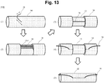
- the optical fiber cable illustrated in Fig. 13 includes an inner layer sheath 12, a metal sheath 13, a metal sheath nick 13-1, an outer layer sheath 14, an outer sheath tearing string 15, an inner sheath tearing string 16, and a fishing line 21.
- the fishing line 21 is an exemplary string for peeling off the outer layer sheath 14.
- the outer layer sheath 14 is peeled off partly by the fishing line 21 (see Fig. 13(1) ), and the metal sheath nick 13-1 is exposed (see Fig. 13(2) ).
- the metal sheath nick 13-1 is an outer edge of a part where the metal sheath 13 is double-wounded.
- the outer layer sheath 14 and the metal sheath 13 are peeled off from the exposed metal sheath nick 13-1 in a circumferential direction to expose the outer sheath tearing string 15 (see Fig. 13(3) ).
- the metal sheath 13 and the outer layer sheath 14 are torn to expose the inner layer sheath 12 (see Fig. 13(4) ).
- the inner layer sheath 12 is further torn using the inner sheath tearing string 16 (see Fig. 13(5) ). After tearing the inner layer sheath 12, the optical fibers of the cable core can be taken out.
- the optical fiber cable illustrated in Fig. 14 includes an inner layer sheath 12, a metal sheath 13, a metal sheath nick 13-1, an outer layer sheath 14, a protective sheath tearing string 18, and a fishing line 21.
- the fishing line 21 is an exemplary string for peeling off the outer layer sheath 14.
- the outer layer sheath 14 is peeled off partly by the fishing line 21 (see Fig. 14(1) ), and the metal sheath nick 13-1 is exposed (see Fig. 14(2) ).
- the metal sheath nick 13-1 is an outer edge of a part where the metal sheath 13 is double-wounded.
- the outer layer sheath 14 and the metal sheath 13 are peeled off from the exposed metal sheath nick 13-1 in a circumferential direction to expose the inner layer sheath 12 (see Fig. 14(3) ).
- the inner layer sheath 12, the metal sheath 13, and the outer layer sheath 14 are torn using the protective sheath tearing string 18 (see Fig. 14(4) ). After tearing the inner layer sheath 12, optical fibers of the cable core can be taken out.
- the present disclosure relates to optical fiber cables provided with the countermeasure against bird, insect, and animal damages, and can be widely used in the communications industry.
Landscapes
- Physics & Mathematics (AREA)
- General Physics & Mathematics (AREA)
- Optics & Photonics (AREA)
- Light Guides In General And Applications Therefor (AREA)
- Insulated Conductors (AREA)
Abstract
Description
- The present disclosure relates to an optical fiber cable that can protect a cable core even if it is bitten by animals and is easy in taking out the cable core.
- In an area where optical fibers may be damaged because of the batting by birds such as woodpeckers or the biting by animals such as squirrels, optical fiber cables each incorporating a metal sheath are used as a countermeasure against bird, insect, and animal damages (see, for example, Patent Literature 1). A cross-sectional structure of a related optical fiber cable will be described with reference to
Fig. 1 . The optical fiber cable illustrated inFig. 1 includes acable core 51, ametal sheath 52, and apolyethylene jacket 53. The optical fiber cable provided with the bird-insect-animal damage countermeasure is formed from thecable core 51, themetal sheath 52 coated so as to cover thecable core 51, and thepolyethylene jacket 53. The optical fiber cable has themetal sheath 52, and thus when accessing thecable core 51 from the optical fiber cable, a high-strength cable jacket cutter is used as a dedicated tool to tear themetal sheath 52. - However, when tearing the metal sheath using the high-strength cable jacket cutter, which is the dedicated tool, an event in which an optical fiber accommodated in the
cable core 51 is cut unintentionally because of excessive entering of a blade of the tool occurs occasionally. In addition, the work for tearing the metal sheath while making fine adjustment to avoid excessive entering of the blade is highly skillful, and accordingly the work is time consuming. - Patent Literature 1:
Japanese Patent Laid-Open No. 62-117213 - An object of the present disclosure is to facilitate tearing a metal sheath even in a case where the metal sheath is incorporated in an optical fiber cable.
- To achieve the above object, the optical fiber cable of the present disclosure includes an outer sheath tearing string extending in a longitudinal direction inside the metal sheath.
- Including the outer sheath tearing string can facilitate tearing the metal sheath.
- Specifically, the optical fiber cable of the present disclosure includes a cable core arranged at a central portion and accommodating a plurality of optical fibers gathered together, an inner layer sheath arranged on an outer circumference of the cable core and sheathing the cable core, a metal sheath arranged on an outer circumference of the inner layer sheath and wound around the inner layer sheath, an outer layer sheath arranged on an outer circumference of the metal sheath and sheathing the metal sheath, and at least one outer sheath tearing string arranged in a longitudinal direction inside the metal sheath.
- Including the outer sheath tearing string can facilitate tearing the metal sheath.
- In the optical fiber cable of the present disclosure, the outer sheath tearing string may be arranged between the metal sheath and the inner layer sheath. Including the outer sheath tearing string can facilitate tearing the metal sheath.
- In the optical fiber cable of the present disclosure, the outer sheath tearing string may be arranged in such a manner that at least a part thereof is embedded in an outer peripheral surface of the inner layer sheath.
- This arrangement can prevent the outer sheath tearing string from moving in the longitudinal direction inside the metal sheath.
- The optical fiber cable of the present disclosure may further include at least one inner sheath tearing string arranged in a longitudinal direction inside a layer of the inner layer sheath.
- Including the inner sheath tearing string can facilitate tearing the inner layer sheath.
- The optical fiber cable of the present disclosure may further include a continuous protrusion arranged on the outer peripheral surface of the inner layer sheath and extending along the outer sheath tearing string.
- Identifying a position of the outer sheath tearing string becomes easy.
- The optical fiber cable of the present disclosure may further include the continuous protrusion arranged on the outer peripheral surface of the inner layer sheath and extending along the outer sheath tearing string, and the inner sheath tearing string and the outer sheath tearing string may be arranged on the same radial axis of the optical fiber cable.
- Identifying the positions of the inner sheath tearing string and the outer sheath tearing string becomes easy.
- In the optical fiber cable of the present disclosure, it is desirable that the metal sheath has a part single-wounded and the rest double-wounded around the outer circumference of the cable core, and the at least one outer sheath tearing string is arranged inside the single-wounded part.
- The outer sheath tearing string facilitates tearing the metal sheath.
- To achieve the above object, the optical fiber cable of the present disclosure includes a protective sheath tearing string provided in a longitudinal direction inside a layer of an inner layer sheath.
- Including the protective sheath tearing string can facilitate tearing the inner layer sheath, the metal sheath, and the outer layer sheath.
- Specifically, the optical fiber cable of the present disclosure includes a cable core arranged at a central portion and accommodating a plurality of optical fibers gathered together, an inner layer sheath arranged on an outer circumference of the cable core and sheathing the cable core, a metal sheath arranged outside the inner layer sheath and wound around the inner layer sheath, an outer layer sheath arranged on an outer circumference of the metal sheath and sheathing the metal sheath, and at least one protective sheath tearing string arranged in a longitudinal direction inside a layer of the inner layer sheath.
- The protective sheath tearing string can facilitate tearing the inner layer sheath, the metal sheath, and the outer layer sheath.
- The optical fiber cable of the present disclosure may further include a continuous protrusion arranged on an outer peripheral surface of the inner layer sheath and extending along the protective sheath tearing string.
- Identifying a position of the protective sheath tearing string becomes easy.
- In the optical fiber cable of the present disclosure, it is desirable that the metal sheath has a part single-wounded and the rest double-wounded around the outer circumference of the cable core, and the at least one protective sheath tearing string is arranged inside the single-wounded part.
- The protective sheath tearing string facilitates tearing the metal sheath.
- Each aspect of the above disclosure can be combined with another one if it is possible.
- According to the present disclosure, it is possible to facilitate tearing a metal sheath even when the metal sheath is incorporated in an optical fiber cable.
-
- [
Fig. 1] Fig. 1 is a diagram illustrating a structure of a related optical fiber cable. - [
Fig. 2] Fig. 2 is a diagram illustrating an exemplary structure of an optical fiber cable according to the present disclosure. - [
Fig. 3] Fig. 3 is a diagram illustrating an exemplary structure of the optical fiber cable according to the present disclosure. - [
Fig. 4] Fig. 4 is a diagram illustrating an exemplary structure of the optical fiber cable according to the present disclosure. - [
Fig. 5] Fig. 5 is a diagram illustrating an exemplary structure of the optical fiber cable according to the present disclosure. - [
Fig. 6] Fig. 6 is a diagram illustrating an exemplary structure of the optical fiber cable according to the present disclosure. - [
Fig. 7] Fig. 7 is a diagram illustrating an exemplary structure of the optical fiber cable according to the present disclosure. - [
Fig. 8] Fig. 8 is a diagram illustrating an exemplary structure of the optical fiber cable according to the present disclosure. - [
Fig. 9] Fig. 9 is a diagram illustrating an exemplary structure of the optical fiber cable according to the present disclosure. - [
Fig. 10] Fig. 10 is a diagram illustrating an exemplary structure of the optical fiber cable according to the present disclosure. - [
Fig. 11] Fig. 11 is a diagram illustrating an exemplary structure of the optical fiber cable according to the present disclosure. - [
Fig. 12] Fig. 12 is a diagram illustrating a structure of the optical fiber cable according to the present disclosure. - [
Fig. 13] Fig. 13 is a diagram illustrating a workflow on or with the optical fiber cable according to the present disclosure. - [
Fig. 14] Fig. 14 is a diagram illustrating a workflow on or with the optical fiber cable according to the present disclosure. - Hereinafter, embodiments of the present disclosure will be described in detail below with reference to attached drawings. The present disclosure is not limited to the following embodiments. These embodiments are merely examples, and the present disclosure can be carried out in the form of various modifications and improvements, based on the knowledge of those skilled in the art, being made. In the present specification and the drawings, constituent components suffixed by the same reference numerals shall indicate the same components.
- An exemplary cross-sectional structure of an optical fiber cable according to the present disclosure will be described with reference to
Fig. 2 . The optical fiber cable illustrated inFig. 2 includes acable core 11, aninner layer sheath 12, ametal sheath 13, anouter layer sheath 14, and an outersheath tearing string 15. Thecable core 11 is arranged at a central portion of the optical fiber cable, and includes a plurality of optical fibers gathered together. Theinner layer sheath 12 is arranged on an outer circumference of thecable core 11 to sheath thecable core 11. Theinner layer sheath 12 may include a tension member that protects the optical fibers against a tensile force acting on the optical fiber cable. The material of theinner layer sheath 12 is, for example, polyethylene, frame-retardant polyethylene, polyvinyl chloride, or the like. Thecable core 11 and theinner layer sheath 12 are collectively referred to as a cable body. Themetal sheath 13 is arranged on an outer circumference of theinner layer sheath 12, and is wound around theinner layer sheath 12. The material of themetal sheath 13 is, for example, stainless steel, steel, iron or the like. Theouter layer sheath 14 is arranged on an outer circumference of themetal sheath 13 to sheath themetal sheath 13. The material of theouter layer sheath 14 is, for example, polyethylene, frame-retardant polyethylene, polyvinyl chloride, or the like. Themetal sheath 13 and theouter layer sheath 14 are collectively referred to as an external sheath. The optical fiber cable according to the present disclosure includes at least one outersheath tearing string 15 arranged in the longitudinal direction inside themetal sheath 13 to tear themetal sheath 13 and theouter layer sheath 14. The outersheath tearing string 15 is required to be arranged inside themetal sheath 13. The at least one outersheath tearing string 15 needs to be provided, or two or more outer sheath tearing strings may be provided. The material of the outersheath tearing string 15 is, for example, Tetron fiber, Kevlar fiber, aramid fiber, polyester fiber, or the like, which are excellent in tensile strength and can be used as they are or twisted together. These structures are the same in the following embodiments. - In the optical fiber cable according to the present embodiment, the outer
sheath tearing string 15 may be arranged between themetal sheath 13 and theinner layer sheath 12, as illustrated inFig. 2 . Arranging the outersheath tearing string 15 between themetal sheath 13 and theinner layer sheath 12 facilitates taking out the outersheath tearing string 15. - Even if there is the
metal sheath 13 introduced as the countermeasure against bird, insect, and animal damages, providing the outersheath tearing string 15 can facilitate tearing themetal sheath 13 and theouter layer sheath 14. That is, the optical fiber cable can be disassembled using the outersheath tearing string 15, without using a dedicated tool, and without damaging the optical fiber. The disassembling method using the outersheath tearing string 15 requires no high-degree skill and can shorten the required time. - An exemplary cross-sectional structure of the optical fiber cable according to the present disclosure will be described with reference to
Fig. 3 . The optical fiber cable illustrated inFig. 3 includes acable core 11, aninner layer sheath 12, ametal sheath 13, anouter layer sheath 14, and an outersheath tearing string 15. At least a part of the outersheath tearing string 15 may be embedded in an outer peripheral surface of theinner layer sheath 12. That is, the outersheath tearing string 15 may have a part embedded in theinner layer sheath 12 and another part exposed from theinner layer sheath 12. The outersheath tearing string 15 may be entirely embedded in theinner layer sheath 12. Being partly embedded in this case indicates a state where a part of the outersheath tearing string 15 is embedded in theinner layer sheath 12 in a cross section perpendicular to a longitudinal direction of the optical fiber cable, as illustrated inFig. 3 . - Embedding at least a part of the outer
sheath tearing string 15 in theinner layer sheath 12 can prevent the outersheath tearing string 15 from moving in the circumferential direction or coming off in the longitudinal direction between theinner layer sheath 12 and themetal sheath 13. Increasing an embedment rate of the outersheath tearing string 15 in theinner layer sheath 12 enhances the above effect. This results in facilitating tearing themetal sheath 13 and theouter layer sheath 14. - An exemplary cross-sectional structure of the optical fiber cable according to the present disclosure will be described with reference to
Fig. 4 . The optical fiber cable illustrated inFig. 4 includes acable core 11, aninner layer sheath 12, ametal sheath 13, anouter layer sheath 14, an outersheath tearing string 15, and an innersheath tearing string 16. The optical fiber cable according to the present disclosure includes at least one innersheath tearing string 16 that is arranged in a longitudinal direction inside a layer of theinner layer sheath 12 to tear theinner layer sheath 12. - The optical fiber cable illustrated in
Fig. 4 has an exemplary structure including the innersheath tearing string 16 in addition to the optical fiber cable described in theembodiment 1. The at least one innersheath tearing string 16 needs to be provided, or two or more inner sheath tearing strings may be provided. Including the innersheath tearing string 16 can facilitate tearing theinner layer sheath 12. - An exemplary cross-sectional structure of the optical fiber cable according to the present disclosure will be described with reference to
Fig. 5 . The optical fiber cable illustrated inFig. 5 includes acable core 11, aninner layer sheath 12, ametal sheath 13, anouter layer sheath 14, an outersheath tearing string 15, and an innersheath tearing string 16. The optical fiber cable according to the present disclosure includes at least one innersheath tearing string 16 arranged in a longitudinal direction inside a layer of theinner layer sheath 12 to tear theinner layer sheath 12. - The optical fiber cable illustrated in
Fig. 5 has an exemplary structure including the innersheath tearing string 16 in addition to the optical fiber cable described in theembodiment 2. The at least one innersheath tearing string 16 needs to be provided, or two or more inner sheath tearing strings may be provided. Including the innersheath tearing string 16 can facilitate tearing theinner layer sheath 12. - An exemplary cross-sectional structure of the optical fiber cable according to the present disclosure will be described with reference to
Fig. 6 . The optical fiber cable illustrated inFig. 6 includes acable core 11, aninner layer sheath 12, ametal sheath 13, anouter layer sheath 14, an outersheath tearing string 15, and acontinuous protrusion 17. The optical fiber cable according to the present disclosure includes thecontinuous protrusion 17 arranged on an outer peripheral surface of theinner layer sheath 12 and extending along the outersheath tearing string 15. - The optical fiber cable illustrated in
Fig. 6 has an exemplary structure including thecontinuous protrusion 17 in addition to the optical fiber cable described in theembodiment 2. When there are multiple outersheath tearing strings 15, thecontinuous protrusion 17 may be provided along one outersheath tearing string 15, or thecontinuous protrusion 17 may be provided along any one of the multiple outer sheath tearing strings 15. Including thecontinuous protrusion 17 additionally can easily identify a position of the outersheath tearing string 15, and the work for taking out the outersheath tearing string 15 becomes easy. This results in facilitating tearing themetal sheath 13 and theouter layer sheath 14. - An exemplary cross-sectional structure of the optical fiber cable according to the present disclosure will be described with reference to
Fig. 7 . The optical fiber cable illustrated inFig. 7 includes acable core 11, aninner layer sheath 12, ametal sheath 13, anouter layer sheath 14, an outersheath tearing string 15, an innersheath tearing string 16, and acontinuous protrusion 17. The optical fiber cable according to the present disclosure includes thecontinuous protrusion 17 arranged on the outer peripheral surface of theinner layer sheath 12 and extending along the outersheath tearing string 15, and the innersheath tearing string 16 and the outersheath tearing string 15 are arranged on the same radial axis of the optical fiber cable. The radial axis is an axis extending radially in an outer circumference direction from a center point of the optical fiber cable. - The optical fiber cable illustrated in
Fig. 7 has an exemplary structure including thecontinuous protrusion 17 in addition to the optical fiber cable described in theembodiment 4. When there are multiple outersheath tearing strings 15, thecontinuous protrusion 17 may be provided along one outersheath tearing string 15, or thecontinuous protrusion 17 may be provided along any one of the multiple outer sheath tearing strings 15. Including thecontinuous protrusion 17 additionally can easily identify positions of the outersheath tearing string 15 and the innersheath tearing string 16, and the work for taking out the outersheath tearing string 15 becomes easy. This results in facilitating tearing themetal sheath 13 and theouter layer sheath 14. - An exemplary cross-sectional structure of the optical fiber cable according to the present disclosure will be described with reference to
Fig. 8 . The optical fiber cable illustrated inFig. 8 includes acable core 11, aninner layer sheath 12, ametal sheath 13, anouter layer sheath 14, and an outersheath tearing string 15. In the optical fiber cable according to the present disclosure, themetal sheath 13 has a part single-wounded and the rest double-wounded around an outer circumference of thecable core 11, and at least one outersheath tearing string 15 is arranged inside the single-wounded part of themetal sheath 13. - When there is only one outer
sheath tearing string 15, it is desirable that the one outersheath tearing string 15 is arranged inside the single-wounded part of themetal sheath 13. When there are multiple outersheath tearing strings 15, it is desirable that at least one of these outersheath tearing strings 15 is arranged inside the single-wounded part of themetal sheath 13, and it is further desirable that two or more outersheath tearing strings 15 are arranged inside the single-wounded part of themetal sheath 13. Arranging at least one outersheath tearing string 15 inside the single-wounded part of themetal sheath 13 facilitates the work for taking out the outersheath tearing string 15. Further, themetal sheath 13 and theouter layer sheath 14 can be easily torn. The same applies even when thecontinuous protrusion 17 is arranged as in theembodiment - An exemplary design in which there are two outer
sheath tearing strings 15 will be described with reference toFig. 8 . InFig. 8 , when θ1(degree) and θ2(degree) represent angles formed by two lines connecting two outersheath tearing strings 15 and the center point of the optical fiber cable respectively with respect to a line perpendicular to a line connecting a center of the double-wounded part of themetal sheath 13 and the center point of the optical fiber cable, d represents a diameter of a cable body, and L represents a width of themetal sheath 13 in a circumferential direction, it is configured to satisfy the following relationships. 0 <= θ1, θ2 < 90, and
- The validity of Expression (1) was verified using a 24 cores optical fiber cable and a 200 cores optical fiber cable.
Fig. 9 illustrates verification results. InFig. 9 , with the cable body diameter d,angle 01+02, and the width L of themetal sheath 13 in the circumferential direction as parameters, the quality of workability was qualitatively determined when Expression (1) is satisfied ("round mark" in "Expression" column ofFig. 9 ) and when Expression (1) is not satisfied ("X mark" in "Expression" column ofFig. 9 ). It was verified that the workability was good ("round mark" in "workability" column ofFig. 9 ) when Expression (1) was satisfied, and the workability was bad ("X mark") in "workability" column ofFig. 9 ) when Expression (1) was not satisfied. - Adopting such a design can prevent the outer
sheath tearing string 15 from being arranged inside the double-wounded part of themetal sheath 13, and therefore the work for taking out the outersheath tearing string 15 becomes easy. In addition, themetal sheath 13 and theouter layer sheath 14 can be easily torn. AlthoughFig. 8 illustrates the exemplary structure including two outersheath tearing strings 15, even when there are three or more outersheath tearing strings 15, it is desirable to select arbitrary two of them and determine the design so as to satisfy Expression (1). - The optical fiber cable illustrated in
Fig. 8 shows the arrangement of the outersheath tearing string 15 by taking the optical fiber cable described in theembodiment 2 as an example. The structure of the optical fiber cable of the present embodiment is not limited to theembodiment 2 and can be also applied to the optical fiber cable of any one of theembodiments 1 to 6. - An exemplary cross-sectional structure of the optical fiber cable according to the present disclosure will be described with reference to
Fig. 10 . The optical fiber cable illustrated inFig. 10 includes acable core 11, aninner layer sheath 12, ametal sheath 13, anouter layer sheath 14, and a protectivesheath tearing string 18. Thecable core 11 is arranged at a central portion of the optical fiber cable, and includes a plurality of optical fibers gathered together. Theinner layer sheath 12 is arranged on an outer circumference of thecable core 11 to sheath thecable core 11. Theinner layer sheath 12 may include a tension member that protects the optical fibers against a tensile force acting on the optical fiber cable. The material of theinner layer sheath 12 is, for example, polyethylene, frame-retardant polyethylene, polyvinyl chloride, or the like. Thecable core 11 and theinner layer sheath 12 are collectively referred to as a cable body. Themetal sheath 13 is arranged on an outer circumference of theinner layer sheath 12, and is wound around theinner layer sheath 12. The material of themetal sheath 13 is, for example, stainless steel, steel, iron, or the like. Theouter layer sheath 14 is arranged on an outer circumference of themetal sheath 13 to sheath themetal sheath 13. The material of theouter layer sheath 14 is, for example, polyethylene, frame-retardant polyethylene, polyvinyl chloride, or the like. Themetal sheath 13 and theouter layer sheath 14 are collectively referred to as an external sheath. The optical fiber cable according to the present disclosure includes at least one protectivesheath tearing string 18 arranged in the longitudinal direction inside a layer of theinner layer sheath 12 to tear theinner layer sheath 12, themetal sheath 13, and theouter layer sheath 14. The at least one protectivesheath tearing string 18 needs to be provided, or two or more protective sheath tearing strings may be provided. The material of the protectivesheath tearing string 18 is, for example, Tetron fiber, Kevlar fiber, aramid fiber, polyester fiber, or the like, which are excellent in tensile strength and can be used as they are or twisted together. These structures are the same in the following embodiments. - Even if there is the
metal sheath 13 introduced as the countermeasure against bird, insect, and animal damages, providing the protectivesheath tearing string 18 can facilitate tearing theinner layer sheath 12, themetal sheath 13, and theouter layer sheath 14. That is, the optical fiber cable can be disassembled using the protectivesheath tearing string 18, without using a dedicated tool, or without damaging the optical fiber. The disassembling method using the protectivesheath tearing string 18 requires no high-degree skill and can shorten the required time. - An exemplary cross-sectional structure of the optical fiber cable according to the present disclosure will be described with reference to
Fig. 11 . The optical fiber cable illustrated inFig. 11 includes acable core 11, aninner layer sheath 12, ametal sheath 13, anouter layer sheath 14, a protectivesheath tearing string 18, and acontinuous protrusion 17. The optical fiber cable according to the present disclosure includes thecontinuous protrusion 17 arranged on an outer peripheral surface of theinner layer sheath 12 and extending along the protectivesheath tearing string 18. - The optical fiber cable illustrated in
Fig. 11 has an exemplary structure including thecontinuous protrusion 17 in addition to the optical fiber cable described in theembodiment 8. When there are multiple protectivesheath tearing strings 18, thecontinuous protrusion 17 may be provided along one protectivesheath tearing string 18, or thecontinuous protrusion 17 may be provided along any one of the multiple protective sheath tearing strings 18. Including thecontinuous protrusion 17 additionally can easily identify the position of the protectivesheath tearing string 18, and the work for taking out the protectivesheath tearing string 18 becomes easy. This results in facilitating tearing theinner layer sheath 12, themetal sheath 13, and theouter layer sheath 14. - An exemplary cross-sectional structure of the optical fiber cable according to the present disclosure will be described with reference to
Fig. 12 . The optical fiber cable illustrated inFig. 12 includes acable core 11, aninner layer sheath 12, ametal sheath 13, anouter layer sheath 14, and a protectivesheath tearing string 18. In the optical fiber cable according to the present disclosure, themetal sheath 13 has a part single-wounded and the rest double-wounded around the outer circumference of thecable core 11, and at least one protectivesheath tearing string 18 is arranged inside the single-wounded part of themetal sheath 13. - When there is only one protective
sheath tearing string 18, it is desirable that the one protectivesheath tearing string 18 is arranged inside the single-wounded part of themetal sheath 13. When there are multiple protectivesheath tearing strings 18, it is desirable that at least one of these protectivesheath tearing strings 18 is arranged inside the single-wounded part of themetal sheath 13, and it is further desirable that two or more protectivesheath tearing strings 18 are arranged inside the single-wounded part of themetal sheath 13. Arranging at least one protectivesheath tearing string 18 inside the single-wounded part of themetal sheath 13 facilitates the work for taking out the protectivesheath tearing string 18. Further, theinner layer sheath 12, themetal sheath 13, and theouter layer sheath 14 can be easily torn. The same applies even when thecontinuous protrusion 17 is arranged as in theembodiment 9. - An exemplary design in which there are two protective
sheath tearing strings 18 will be described with reference toFig. 12 . InFig. 12 , when θ1(degree) and θ2(degree) represent angles formed by two lines connecting two protectivesheath tearing strings 18 and the center point of the optical fiber cable respectively with respect to a line perpendicular to a line connecting a center of the double-wounded part of themetal sheath 13 and the center point of the optical fiber cable, d represents a diameter of a cable body, and L represents a width of themetal sheath 13 in a circumferential direction, it is configured to satisfy the following relationships. 0 <= θ1, θ2 < 90 and
- The validity of Expression (1) was verified using a 24 cores optical fiber cable and a 200 cores optical fiber cable. Verification results are similar to those of the
embodiment 7, and it was verified that the workability was good when Expression (2) was satisfied, and the workability was bad when Expression (2) was not satisfied. - Adopting such a design can prevent the protective
sheath tearing string 18 from being arranged inside the double-wounded part of themetal sheath 13, and therefore the work for taking out the protectivesheath tearing string 18 becomes easy. In addition, theinner layer sheath 12, themetal sheath 13, and theouter layer sheath 14 can be easily torn. AlthoughFig. 12 illustrates the exemplary structure including two protectivesheath tearing strings 18, even when there are three or more protectivesheath tearing strings 18, it is desirable to select arbitrary two of them and determine the design so as to satisfy Expression (2). - The optical fiber cable illustrated in
Fig. 12 shows the arrangement of the protectivesheath tearing string 18 by taking the optical fiber cable described in theembodiment 8 as an example. The structure of the optical fiber cable of the present embodiment is not limited to theembodiment 8 and can be also applied to the optical fiber cable of theembodiment 9. - An exemplary workflow for removing a metal sheath of the optical fiber cable according to the present disclosure will be described with reference to
Fig. 13 . The optical fiber cable illustrated inFig. 13 includes aninner layer sheath 12, ametal sheath 13, a metal sheath nick 13-1, anouter layer sheath 14, an outersheath tearing string 15, an innersheath tearing string 16, and afishing line 21. Thefishing line 21 is an exemplary string for peeling off theouter layer sheath 14. - First, the
outer layer sheath 14 is peeled off partly by the fishing line 21 (seeFig. 13(1) ), and the metal sheath nick 13-1 is exposed (seeFig. 13(2) ). The metal sheath nick 13-1 is an outer edge of a part where themetal sheath 13 is double-wounded. Next, using a tool such as a nipper, theouter layer sheath 14 and themetal sheath 13 are peeled off from the exposed metal sheath nick 13-1 in a circumferential direction to expose the outer sheath tearing string 15 (seeFig. 13(3) ). Then, using the exposed outersheath tearing string 15, themetal sheath 13 and theouter layer sheath 14 are torn to expose the inner layer sheath 12 (seeFig. 13(4) ). In the case of taking out the cable core (not illustrated) when the innersheath tearing string 16 is arranged, theinner layer sheath 12 is further torn using the inner sheath tearing string 16 (seeFig. 13(5) ). After tearing theinner layer sheath 12, the optical fibers of the cable core can be taken out. - An exemplary workflow for removing a metal sheath of the optical fiber cable according to the present disclosure will be described with reference to
Fig. 14 . The optical fiber cable illustrated inFig. 14 includes aninner layer sheath 12, ametal sheath 13, a metal sheath nick 13-1, anouter layer sheath 14, a protectivesheath tearing string 18, and afishing line 21. Thefishing line 21 is an exemplary string for peeling off theouter layer sheath 14. - First, the
outer layer sheath 14 is peeled off partly by the fishing line 21 (seeFig. 14(1) ), and the metal sheath nick 13-1 is exposed (seeFig. 14(2) ). The metal sheath nick 13-1 is an outer edge of a part where themetal sheath 13 is double-wounded. Next, using a tool such as a nipper, theouter layer sheath 14 and themetal sheath 13 are peeled off from the exposed metal sheath nick 13-1 in a circumferential direction to expose the inner layer sheath 12 (seeFig. 14(3) ). In the case of taking out the cable core (not illustrated), theinner layer sheath 12, themetal sheath 13, and theouter layer sheath 14 are torn using the protective sheath tearing string 18 (seeFig. 14(4) ). After tearing theinner layer sheath 12, optical fibers of the cable core can be taken out. - The present disclosure relates to optical fiber cables provided with the countermeasure against bird, insect, and animal damages, and can be widely used in the communications industry.
-
- 11
- cable core
- 12
- inner layer sheath
- 13
- metal sheath
- 13-1
- metal sheath nick
- 14
- outer layer sheath
- 15
- outer sheath tearing string
- 16
- inner sheath tearing string
- 17
- continuous protrusion
- 18
- protective sheath tearing string
- 21
- fishing line
- 51
- cable core
- 52
- metal sheath
- 53
- polyethylene jacket
Claims (10)
- An optical fiber cable comprising:a cable core arranged at a central portion and accommodating a plurality of optical fibers gathered together;an inner layer sheath arranged on an outer circumference of the cable core and sheathing the cable core;a metal sheath arranged on an outer circumference of the inner layer sheath and wound around the inner layer sheath;an outer layer sheath arranged on an outer circumference of the metal sheath and sheathing the metal sheath; andat least one outer sheath tearing string arranged in a longitudinal direction inside the metal sheath.
- The optical fiber cable according to claim 1, wherein the outer sheath tearing string is arranged between the metal sheath and the inner layer sheath.
- The optical fiber cable according to claim 1, wherein the outer sheath tearing string is arranged in such a manner that at least a part thereof is embedded in an outer peripheral surface of the inner layer sheath.
- The optical fiber cable according to any one of claims 1 to 3, further comprising at least one inner sheath tearing string arranged in a longitudinal direction inside a layer of the inner layer sheath.
- The optical fiber cable according to claim 3 or 4, further comprising a continuous protrusion arranged on the outer peripheral surface of the inner layer sheath and extending along the outer sheath tearing string.
- The optical fiber cable according to claim 4, further comprising a continuous protrusion arranged on the outer peripheral surface of the inner layer sheath and extending along the outer sheath tearing string, wherein the inner sheath tearing string and the outer sheath tearing string are arranged on the same radial axis of the optical fiber cable.
- The optical fiber cable according to any one of claims 1 to 6, whereinthe metal sheath has a part single-wounded and the rest double-wounded around the outer circumference of the cable core, andthe at least one outer sheath tearing string is arranged inside the single-wounded part.
- An optical fiber cable comprising:a cable core arranged at a central portion and accommodating a plurality of optical fibers gathered together;an inner layer sheath arranged on an outer circumference of the cable core and sheathing the cable core;a metal sheath arranged outside the inner layer sheath and wound around the inner layer sheath;an outer layer sheath arranged on an outer circumference of the metal sheath and sheathing the metal sheath; andat least one protective sheath tearing string arranged in a longitudinal direction inside a layer of the inner layer sheath.
- The optical fiber cable according to claim 8, further comprising
a continuous protrusion arranged on an outer peripheral surface of the inner layer sheath and extending along the protective sheath tearing string. - The optical fiber cable according to claim 8 or 9, wherein
the metal sheath has a part single-wounded and the rest double-wounded around the outer circumference of the cable core, and the at least one protective sheath tearing string is arranged inside the single-wounded part.
Applications Claiming Priority (2)
| Application Number | Priority Date | Filing Date | Title |
|---|---|---|---|
| JP2019024863A JP7363043B2 (en) | 2019-02-14 | 2019-02-14 | fiber optic cable |
| PCT/JP2020/003591 WO2020166369A1 (en) | 2019-02-14 | 2020-01-31 | Optical fiber cable |
Publications (2)
| Publication Number | Publication Date |
|---|---|
| EP3926377A1 true EP3926377A1 (en) | 2021-12-22 |
| EP3926377A4 EP3926377A4 (en) | 2022-11-09 |
Family
ID=72044638
Family Applications (1)
| Application Number | Title | Priority Date | Filing Date |
|---|---|---|---|
| EP20754867.8A Pending EP3926377A4 (en) | 2019-02-14 | 2020-01-31 | Optical fiber cable |
Country Status (5)
| Country | Link |
|---|---|
| US (1) | US11947175B2 (en) |
| EP (1) | EP3926377A4 (en) |
| JP (1) | JP7363043B2 (en) |
| CN (1) | CN113366358B (en) |
| WO (1) | WO2020166369A1 (en) |
Families Citing this family (2)
| Publication number | Priority date | Publication date | Assignee | Title |
|---|---|---|---|---|
| US20240053559A1 (en) | 2021-05-17 | 2024-02-15 | Fujikura Ltd. | Optical cable |
| WO2024195397A1 (en) * | 2023-03-20 | 2024-09-26 | 株式会社フジクラ | Optical fiber cable and method for manufacturing optical fiber cable |
Family Cites Families (16)
| Publication number | Priority date | Publication date | Assignee | Title |
|---|---|---|---|---|
| JPS62117213A (en) | 1985-11-18 | 1987-05-28 | 日本電信電話株式会社 | High-strength jacketed communication cable |
| US5642452A (en) | 1995-02-21 | 1997-06-24 | Sumitomo Electric Lightwave Corp. | Water-blocked optical fiber communications cable |
| US6259844B1 (en) * | 1997-12-15 | 2001-07-10 | Siecor Operations, Llc | Strengthened fiber optic cable |
| JP2002098871A (en) * | 2000-09-22 | 2002-04-05 | Sumitomo Electric Ind Ltd | Optical fiber cable |
| US6519399B2 (en) | 2001-02-19 | 2003-02-11 | Corning Cable Systems Llc | Fiber optic cable with profiled group of optical fibers |
| JP4018441B2 (en) | 2002-05-08 | 2007-12-05 | トヨクニ電線株式会社 | Optical communication trunk cable |
| JP2007011020A (en) | 2005-06-30 | 2007-01-18 | Sumitomo Electric Ind Ltd | Optical fiber cable |
| EP2784788A1 (en) * | 2013-03-28 | 2014-10-01 | Alcatel-Lucent Shanghai Bell Co., Ltd. | Cable and method of manufacturing a cable |
| CN103412379A (en) * | 2013-07-29 | 2013-11-27 | 成都亨通光通信有限公司 | Novel fire-resistant optical cable |
| WO2017027283A1 (en) * | 2015-08-11 | 2017-02-16 | Corning Optical Communications LLC | Optical fiber cable |
| JP6134365B2 (en) | 2015-10-09 | 2017-05-24 | 株式会社フジクラ | Fiber optic cable |
| JP6298503B2 (en) * | 2016-08-04 | 2018-03-20 | 株式会社フジクラ | Fiber optic cable |
| US10527808B2 (en) | 2017-05-30 | 2020-01-07 | Sterlite Technologies Limited | Flame retardant optical fiber cable |
| JP6676032B2 (en) | 2017-12-21 | 2020-04-08 | 株式会社フジクラ | Fiber optic cable |
| JP6851960B2 (en) | 2017-12-21 | 2021-03-31 | 株式会社フジクラ | Fiber optic cable |
| JP7182509B2 (en) * | 2019-04-25 | 2022-12-02 | 株式会社フジクラ | fiber optic cable |
-
2019
- 2019-02-14 JP JP2019024863A patent/JP7363043B2/en active Active
-
2020
- 2020-01-31 WO PCT/JP2020/003591 patent/WO2020166369A1/en unknown
- 2020-01-31 EP EP20754867.8A patent/EP3926377A4/en active Pending
- 2020-01-31 US US17/430,419 patent/US11947175B2/en active Active
- 2020-01-31 CN CN202080010984.5A patent/CN113366358B/en active Active
Also Published As
| Publication number | Publication date |
|---|---|
| EP3926377A4 (en) | 2022-11-09 |
| JP2020134597A (en) | 2020-08-31 |
| US11947175B2 (en) | 2024-04-02 |
| CN113366358A (en) | 2021-09-07 |
| CN113366358B (en) | 2023-12-26 |
| JP7363043B2 (en) | 2023-10-18 |
| US20220155547A1 (en) | 2022-05-19 |
| WO2020166369A1 (en) | 2020-08-20 |
Similar Documents
| Publication | Publication Date | Title |
|---|---|---|
| US11215780B2 (en) | Optical fiber cable | |
| EP3926377A1 (en) | Optical fiber cable | |
| TWI640806B (en) | Optical fiber cable | |
| CN210119616U (en) | Rat-proof optical cable | |
| JP7444833B2 (en) | How to disassemble optical fiber cable and optical fiber cable | |
| JP2012155230A (en) | Optical fiber cable, and branching method for optical fiber cable | |
| KR102072402B1 (en) | Temperature measurement device and method of manufacturing temperature measurement device | |
| WO2024134730A1 (en) | Optical fiber cable | |
| JP2007034160A (en) | Optical fiber cable | |
| WO2024134731A1 (en) | Optical fiber cable | |
| JP2007034159A (en) | Optical fiber cable | |
| JP2006011166A (en) | Fiber optic cable | |
| JP2006195110A (en) | Tape drop cable | |
| TW201131233A (en) | Optical fiber cable and method of taking out optical fiber | |
| US5531026A (en) | Stripping tool for armored fiber optic cables | |
| JP2009217195A (en) | Optical fiber cable | |
| JP2009169067A (en) | Optical cable | |
| JP2004252033A (en) | Optical cable and manufacturing method therefor | |
| JP2020106568A (en) | Optical fiber cable | |
| JPH02156206A (en) | Optical fiber cable | |
| JP2009186714A (en) | Optical fiber cable | |
| JPH11109192A (en) | Optical fiber unit for optical submarine cable | |
| JP2008129168A (en) | Optical fiber cable | |
| JP2006251259A (en) | Tool for stripping tension protective wire for optical cable | |
| JP2004264473A (en) | Optical fiber cable |
Legal Events
| Date | Code | Title | Description |
|---|---|---|---|
| STAA | Information on the status of an ep patent application or granted ep patent |
Free format text: STATUS: THE INTERNATIONAL PUBLICATION HAS BEEN MADE |
|
| PUAI | Public reference made under article 153(3) epc to a published international application that has entered the european phase |
Free format text: ORIGINAL CODE: 0009012 |
|
| STAA | Information on the status of an ep patent application or granted ep patent |
Free format text: STATUS: REQUEST FOR EXAMINATION WAS MADE |
|
| 17P | Request for examination filed |
Effective date: 20210914 |
|
| AK | Designated contracting states |
Kind code of ref document: A1 Designated state(s): AL AT BE BG CH CY CZ DE DK EE ES FI FR GB GR HR HU IE IS IT LI LT LU LV MC MK MT NL NO PL PT RO RS SE SI SK SM TR |
|
| DAV | Request for validation of the european patent (deleted) | ||
| DAX | Request for extension of the european patent (deleted) | ||
| A4 | Supplementary search report drawn up and despatched |
Effective date: 20221010 |
|
| RIC1 | Information provided on ipc code assigned before grant |
Ipc: G02B 6/44 20060101AFI20221004BHEP |
|
| STAA | Information on the status of an ep patent application or granted ep patent |
Free format text: STATUS: EXAMINATION IS IN PROGRESS |
|
| 17Q | First examination report despatched |
Effective date: 20230705 |
|
| GRAP | Despatch of communication of intention to grant a patent |
Free format text: ORIGINAL CODE: EPIDOSNIGR1 |
|
| STAA | Information on the status of an ep patent application or granted ep patent |
Free format text: STATUS: GRANT OF PATENT IS INTENDED |