EP3925828B1 - Overhead console - Google Patents
Overhead console Download PDFInfo
- Publication number
- EP3925828B1 EP3925828B1 EP21175264.7A EP21175264A EP3925828B1 EP 3925828 B1 EP3925828 B1 EP 3925828B1 EP 21175264 A EP21175264 A EP 21175264A EP 3925828 B1 EP3925828 B1 EP 3925828B1
- Authority
- EP
- European Patent Office
- Prior art keywords
- mirror surface
- mirror
- vehicle interior
- light source
- see
- Prior art date
- Legal status (The legal status is an assumption and is not a legal conclusion. Google has not performed a legal analysis and makes no representation as to the accuracy of the status listed.)
- Active
Links
Images




Classifications
-
- B—PERFORMING OPERATIONS; TRANSPORTING
- B60—VEHICLES IN GENERAL
- B60R—VEHICLES, VEHICLE FITTINGS, OR VEHICLE PARTS, NOT OTHERWISE PROVIDED FOR
- B60R1/00—Optical viewing arrangements; Real-time viewing arrangements for drivers or passengers using optical image capturing systems, e.g. cameras or video systems specially adapted for use in or on vehicles
- B60R1/12—Mirror assemblies combined with other articles, e.g. clocks
- B60R1/1207—Mirror assemblies combined with other articles, e.g. clocks with lamps; with turn indicators
-
- B—PERFORMING OPERATIONS; TRANSPORTING
- B60—VEHICLES IN GENERAL
- B60R—VEHICLES, VEHICLE FITTINGS, OR VEHICLE PARTS, NOT OTHERWISE PROVIDED FOR
- B60R22/00—Safety belts or body harnesses in vehicles
- B60R22/48—Control systems, alarms, or interlock systems, for the correct application of the belt or harness
-
- B—PERFORMING OPERATIONS; TRANSPORTING
- B60—VEHICLES IN GENERAL
- B60K—ARRANGEMENT OR MOUNTING OF PROPULSION UNITS OR OF TRANSMISSIONS IN VEHICLES; ARRANGEMENT OR MOUNTING OF PLURAL DIVERSE PRIME-MOVERS IN VEHICLES; AUXILIARY DRIVES FOR VEHICLES; INSTRUMENTATION OR DASHBOARDS FOR VEHICLES; ARRANGEMENTS IN CONNECTION WITH COOLING, AIR INTAKE, GAS EXHAUST OR FUEL SUPPLY OF PROPULSION UNITS IN VEHICLES
- B60K35/00—Instruments specially adapted for vehicles; Arrangement of instruments in or on vehicles
- B60K35/10—Input arrangements, i.e. from user to vehicle, associated with vehicle functions or specially adapted therefor
-
- B—PERFORMING OPERATIONS; TRANSPORTING
- B60—VEHICLES IN GENERAL
- B60Q—ARRANGEMENT OF SIGNALLING OR LIGHTING DEVICES, THE MOUNTING OR SUPPORTING THEREOF OR CIRCUITS THEREFOR, FOR VEHICLES IN GENERAL
- B60Q3/00—Arrangement of lighting devices for vehicle interiors; Lighting devices specially adapted for vehicle interiors
- B60Q3/20—Arrangement of lighting devices for vehicle interiors; Lighting devices specially adapted for vehicle interiors for lighting specific fittings of passenger or driving compartments; mounted on specific fittings of passenger or driving compartments
- B60Q3/208—Sun roofs; Windows
-
- B—PERFORMING OPERATIONS; TRANSPORTING
- B60—VEHICLES IN GENERAL
- B60Q—ARRANGEMENT OF SIGNALLING OR LIGHTING DEVICES, THE MOUNTING OR SUPPORTING THEREOF OR CIRCUITS THEREFOR, FOR VEHICLES IN GENERAL
- B60Q3/00—Arrangement of lighting devices for vehicle interiors; Lighting devices specially adapted for vehicle interiors
- B60Q3/70—Arrangement of lighting devices for vehicle interiors; Lighting devices specially adapted for vehicle interiors characterised by the purpose
- B60Q3/74—Arrangement of lighting devices for vehicle interiors; Lighting devices specially adapted for vehicle interiors characterised by the purpose for overall compartment lighting; for overall compartment lighting in combination with specific lighting, e.g. room lamps with reading lamps
-
- B—PERFORMING OPERATIONS; TRANSPORTING
- B60—VEHICLES IN GENERAL
- B60Q—ARRANGEMENT OF SIGNALLING OR LIGHTING DEVICES, THE MOUNTING OR SUPPORTING THEREOF OR CIRCUITS THEREFOR, FOR VEHICLES IN GENERAL
- B60Q3/00—Arrangement of lighting devices for vehicle interiors; Lighting devices specially adapted for vehicle interiors
- B60Q3/80—Circuits; Control arrangements
-
- B—PERFORMING OPERATIONS; TRANSPORTING
- B60—VEHICLES IN GENERAL
- B60Q—ARRANGEMENT OF SIGNALLING OR LIGHTING DEVICES, THE MOUNTING OR SUPPORTING THEREOF OR CIRCUITS THEREFOR, FOR VEHICLES IN GENERAL
- B60Q3/00—Arrangement of lighting devices for vehicle interiors; Lighting devices specially adapted for vehicle interiors
- B60Q3/80—Circuits; Control arrangements
- B60Q3/82—Switches specially adapted for vehicle interior lighting, e.g. switching by tilting the lens
-
- B—PERFORMING OPERATIONS; TRANSPORTING
- B60—VEHICLES IN GENERAL
- B60R—VEHICLES, VEHICLE FITTINGS, OR VEHICLE PARTS, NOT OTHERWISE PROVIDED FOR
- B60R1/00—Optical viewing arrangements; Real-time viewing arrangements for drivers or passengers using optical image capturing systems, e.g. cameras or video systems specially adapted for use in or on vehicles
- B60R1/008—Optical viewing arrangements; Real-time viewing arrangements for drivers or passengers using optical image capturing systems, e.g. cameras or video systems specially adapted for use in or on vehicles allowing the driver to see passengers, e.g. for busses
-
- B—PERFORMING OPERATIONS; TRANSPORTING
- B60—VEHICLES IN GENERAL
- B60R—VEHICLES, VEHICLE FITTINGS, OR VEHICLE PARTS, NOT OTHERWISE PROVIDED FOR
- B60R1/00—Optical viewing arrangements; Real-time viewing arrangements for drivers or passengers using optical image capturing systems, e.g. cameras or video systems specially adapted for use in or on vehicles
- B60R1/12—Mirror assemblies combined with other articles, e.g. clocks
-
- B—PERFORMING OPERATIONS; TRANSPORTING
- B60—VEHICLES IN GENERAL
- B60R—VEHICLES, VEHICLE FITTINGS, OR VEHICLE PARTS, NOT OTHERWISE PROVIDED FOR
- B60R1/00—Optical viewing arrangements; Real-time viewing arrangements for drivers or passengers using optical image capturing systems, e.g. cameras or video systems specially adapted for use in or on vehicles
- B60R1/12—Mirror assemblies combined with other articles, e.g. clocks
- B60R2001/1215—Mirror assemblies combined with other articles, e.g. clocks with information displays
-
- B—PERFORMING OPERATIONS; TRANSPORTING
- B60—VEHICLES IN GENERAL
- B60R—VEHICLES, VEHICLE FITTINGS, OR VEHICLE PARTS, NOT OTHERWISE PROVIDED FOR
- B60R1/00—Optical viewing arrangements; Real-time viewing arrangements for drivers or passengers using optical image capturing systems, e.g. cameras or video systems specially adapted for use in or on vehicles
- B60R1/12—Mirror assemblies combined with other articles, e.g. clocks
- B60R2001/1238—Mirror assemblies combined with other articles, e.g. clocks with vanity mirrors
-
- B—PERFORMING OPERATIONS; TRANSPORTING
- B60—VEHICLES IN GENERAL
- B60R—VEHICLES, VEHICLE FITTINGS, OR VEHICLE PARTS, NOT OTHERWISE PROVIDED FOR
- B60R11/00—Arrangements for holding or mounting articles, not otherwise provided for
- B60R2011/0001—Arrangements for holding or mounting articles, not otherwise provided for characterised by position
- B60R2011/0003—Arrangements for holding or mounting articles, not otherwise provided for characterised by position inside the vehicle
- B60R2011/0028—Ceiling, e.g. roof rails
-
- B—PERFORMING OPERATIONS; TRANSPORTING
- B60—VEHICLES IN GENERAL
- B60R—VEHICLES, VEHICLE FITTINGS, OR VEHICLE PARTS, NOT OTHERWISE PROVIDED FOR
- B60R22/00—Safety belts or body harnesses in vehicles
- B60R22/48—Control systems, alarms, or interlock systems, for the correct application of the belt or harness
- B60R2022/4866—Displaying or indicating arrangements thereof
Definitions
- the present invention relates to an overhead console to be mounted on a ceiling of a vehicle interior at a location near a windshield.
- an overhead console that is mounted on a ceiling of a vehicle interior at a location near a windshield is known (for example, refer to Patent Document 1).
- various operation switches and such are mounted to the overhead console.
- the overhead console described in Patent Document 2 has a problem that, when a display unit for displaying the symbol is placed too close to the illumination light source to downsize the overhead console, it could be difficult to see the symbol when the illumination light source is turned on simultaneously with the display of the symbol due to the illumination being too bright. It is thus desirable to place the display unit at a location some distance from the illumination light source. This, however, requires to provide a circuit board for the display unit separately for a mounting board for the illumination light source, making it difficult to downsize the overhead console.
- the symbol indicating the seatbelt fastening state was given as one example of a symbol to be displayed by the display function provided on the overhead console, and the problem that there is difficulty in downsizing the overhead console has been explained. This problem, however, could occur in providing the display function in the overhead console regardless of a specific symbol to be displayed by the display function.
- an object of the present invention is to provide an overhead console that includes a display function and that can be downsized.
- an overhead console including a console housing attachable to a ceiling of a vehicle interior at a location near a windshield, an illumination board on which an illumination light source is mounted and which is accommodated in the console housing, a vehicle interior checking mirror installed at a location closer to the windshield than the illumination board and arranged capable of being in a mirror surface visible position in which a mirror surface is visually recognizable by a passenger, a mirror surface light source that is mounted on the illumination board together with the illumination light source and that is configured to emit light toward the mirror surface of the vehicle interior checking mirror in the mirror surface visible position, and a see-through display plate that is a display plate capable of transparently displaying a symbol indicating predetermined information, wherein the see-through display plate is provided in the console housing at a location between the mirror surface light source and the mirror surface so as not to hinder the passenger from visually recognizing the mirror surface and so as to face a partial region of the mirror surface, and wherein the see-through display plate is configured
- the symbol is displayed in the partial region of the mirror surface of the vehicle interior checking mirror installed at a location closer to the windshield than the illumination board on which the illumination light source is mounted. That is, the symbol is displayed at a location some distance from the illumination light source, thus it is possible to prevent a decrease in the visibility of the symbol due to bright illumination.
- the mirror surface light source for displaying the symbol on the mirror surface is mounted on the illumination board together with the illumination light source, thus there is no need to separately provide a circuit board for displaying the symbol, allowing to downsize the overhead console.
- FIG. 1 is an external perspective view of a vehicle interior of a motor vehicle to which an overhead console according to one embodiment is applied.
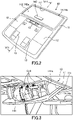
- FIG. 2 is an external perspective view of a surface of the overhead console shown in FIG. 1 which can be seen when looking up from a seat.
- An overhead console 10 of this embodiment is a device configured to be attached to a ceiling R10 of a vehicle interior C10 at a location near a windshield W10.
- the overhead console 10 includes a console housing 11, an illumination 12, a switch 13 for turning on the illumination, and a vehicle interior checking mirror 14.
- the console housing 11 is a resin housing attached to the ceiling R10 of the vehicle interior C10 near the windshield W10.
- the illuminations 12 are provided on the right and left sides in a pair, and are configured to illuminate the vehicle interior C10 with light from a later-described illumination light source.
- a vehicle interior checking mirror 14 is a mirror installed in a manner capable of being in a mirror surface visible position 14a in which a mirror surface 141 is visually recognizable by a passenger.
- an accommodating space 111 for accommodating the vehicle interior checking mirror 14 is provided inside the console housing 11.
- the vehicle interior checking mirror 14 is installed to the console housing 11 so as to be movable along an arrow D11 between the mirror surface visible position 14a and an accommodated position 14b in which the vehicle interior checking mirror 14 is accommodated in the accommodating space 111.
- the vehicle interior checking mirror 14 is provided with a movement switch 143 for moving the vehicle interior checking mirror 14 to the mirror surface visible position 14a, the movement switch 143 being disposed on a bottom face 142a of a mirror housing 142 which is flush with a surface of the console housing 11 in the accommodated position 14b.
- the movement switch 143 is pressed as shown by an arrow D12 in FIG. 1 , the vehicle interior checking mirror 14 is moved from the accommodated position 14b to the mirror surface visible position 14a.
- the vehicle interior checking mirror 14 in the mirror surface visible position 14a is used not only for checking the vehicle interior, but also for providing a seatbelt warning to a passenger in the rear seat, the seatbelt warning being a warning related to fastening of a seatbelt.
- FIG. 3 is a schematic diagram showing how the vehicle interior checking mirror shown in FIG. 1 which is in the mirror surface visible position is used to provide the seatbelt warning to a passenger in the rear seat.
- the mirror surface 141 of the vehicle interior checking mirror 14 has a curved surface such that it is visible to all passengers including a passenger in the rear seat, a passenger in a front passenger's seat and a driver.
- a symbol G10 indicating predetermined warning information to warn and urge this passenger to fasten the seatbelt is displayed.
- This symbol G10 is displayed in a partial region 141a of the vehicle interior checking mirror surface 141 in the mirror surface visible position 14a, the partial region 141a being arranged along an end of the vehicle interior checking mirror surface 141 near the accommodating space 111 of the console housing 11.
- the symbols G10 are provided so as to form pairs with the three rear seats, respectively, and the symbol G10 that corresponds to the rear seat in which a passenger who is not fastening the seatbelt is seated is to be displayed in the partial region 141a of the mirror surface 141.
- FIG. 3 shows an example in which passengers in all of the three rear seats are not fastening their seatbelts, thus all of the three symbols G10 are being displayed.
- the overhead console 10 of this embodiment is configured as explained below to display the warning symbol G10 described above.
- FIG. 4 is a cross sectional view taken along a line V11-V11 in FIG. 2 showing an internal structure of the overhead console of FIG. 1 to FIG. 3 .
- the internal structure of the overhead console 10 is shown in cross section for two cases, namely, the case where the vehicle interior checking mirror 14 is in the accommodated position 14b, and the case where the vehicle interior checking mirror 14 is in the mirror surface visible position 14a.
- the overhead console 10 of this embodiment includes the console housing 11, the illumination 12, the switch 13, the vehicle interior checking mirror 14, the illumination board 15, a mirror surface light source 16, a see-through display plate 17, and a blocking wall 18.
- the console housing 11 is attached to the ceiling R10 of the vehicle interior C10 near the windshield W10.
- the console housing 11 is formed in a flat rectangular box shape, and the accommodating space 111 for accommodating the vehicle interior checking mirror 14 is provided inside the console housing 11 at a location closer to the windshield W10 than the illumination board 15.
- the illumination 12 is configured to illuminate the vehicle interior C10 with light from an illumination light source 151, and has a light guide part 121 for guiding the light from the illumination light source 151 while diffusing said light.
- the switch 13 is configured to be operated to, for example, turn on and off the illumination 12 and to activate and deactivate the display function for displaying the above-described symbol G10 to provide the seatbelt warning.
- the vehicle interior checking mirror 14 is installed at a location closer to the windshield W10 than the illumination board 15 and is arranged capable of being in the mirror surface visible position 14a in which the mirror surface 141 is visually recognizable by a passenger.
- the vehicle interior checking mirror 14 is installed in the console housing 11 so as to be movable between the mirror surface visible position 14a and the accommodated position 14b in which the vehicle interior checking mirror 14 is accommodated in the accommodating space 111.
- the vehicle interior checking mirror 14 has a mirror housing 142 having a fan-shaped cross section and is installed in the console housing 11 so as to be rotatable around a rotation shaft 145 that penetrates a pivot point of the fan.
- the mirror surface 141 is formed at an arc portion of the fan, and, by rotating the vehicle interior checking mirror 14 around the rotation shaft 145, the mirror surface 141 protrudes from the accommodating space 111 and is retracted in the accommodating space 111 such that a bottom face 142a of the mirror housing 142 is flush with the surface of the console housing 11.
- This movement of the vehicle interior checking mirror 14 is performed by a drive mechanism 144 having a pinion gear 144a and a rack gear 144b provided on the mirror surface 141 side.
- the illumination board 15 is a flat-plate shaped circuit board on which the illumination light source 151 and the switch 13 are mounted and which is accommodated in the console housing 11. Inside the console housing 11, the illumination board 15 is arranged along the ceiling R10 of the vehicle interior C10.
- the mirror surface light source 16 is a light source which is mounted on the illumination board 15 together with the illumination light source 151 and the switch 13, and which is configured to emit light toward the mirror surface 141 of the vehicle interior checking mirror 14 in the mirror surface visible position 14a to display the above-described warning symbol G10.
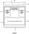
- FIG. 5 is a schematic component placement diagram showing an arrangement of the light source and the switch on the illumination board shown in FIG. 4 .
- FIG. 6 is a schematic block diagram schematically showing the circuit structure of the illumination board shown in FIG. 4
- a various switches-placement area 15b is provided to an area of the console housing 11 of the overhead console 10 located on the opposite side of the accommodating space 111 for the vehicle interior checking mirror 14.
- the various switches-placement area 15b is mounted with a switch 13a for a right illumination light source 151a of the illumination light source 151 and a switch 13b for a left illumination light source 151b of the illumination light source 151.
- the various switches-placement area 15b is mounted with a switch 13c for permitting opening and closing of a door, a switch 13d for turning on at once all the illumination lamps in the vehicle interior C10, and a switch 13e for activating the display function of the warning symbol G10.
- a pair of right and left illumination light source placement areas 15a is provided on the accommodating space 111 side with a gap between each other, the illumination light source placement areas 15a being arranged for placing the pair of right and left illumination light sources 151.
- a light source for illuminating switch 152 that illuminates each switch when an ignition key is turned is also placed within the pair of illumination light source placement areas 15a.
- a mirror surface light source placement area 15c for placing the mirror surface light source 16 is provided between each of the pair of illumination light source placement areas 15a.
- an illumination control circuit 153 configured to control turn on and off of the illumination light source 151 and of the mirror surface light source 16.
- a part of the illumination control circuit 153 is a warning light circuit 161 configured to control turn on and off of the mirror surface light source 16 to display the warning symbol G10.
- the illumination control circuit 153 is connected to a BCM (Body Control Module) 20 which is a module installed outside the overhead console 10 for integrating functions of various lights and a door lock function and such.
- BCM Body Control Module
- the illumination board 15 on which the illumination light source 151 and the mirror surface light source 16 are mounted has been explained above, and now, referring back to FIG. 4 , other components of the overhead console 10 will be explained below.
- the see-through display plate 17 in the overhead console 10 is located in the console housing 11 between the mirror surface light source 16 and the mirror surface 141 so as not to hinder a passenger from visually recognizing the mirror surface 141 and so as to face the partial region 141a of the mirror surface 141.
- This see-through display plate 17 is a display plate capable of transparently displaying the above-described symbol G10 indicating the seatbelt warning information. That is, the see-through display plate 17 allows the light from the mirror surface light source 16 to transmit therethrough to display the symbol G10 in the partial region 141a of the mirror surface 141.
- the partial region 141a of the mirror surface 141 is a region of the mirror surface 141 of the vehicle interior checking mirror 14 along an end of the mirror surface 141 near the accommodating space 111, with the vehicle interior checking mirror 14 in the mirror surface visible position 14a and projecting out from the accommodating space 111.
- the see-through display plate 17 is provided at one wall of walls defining the accommodating space 111 and is located close to an entrance for the vehicle interior checking mirror 14, the one wall corresponding to a facing wall facing the partial region 141a of the mirror surface 141 of the vehicle interior checking mirror 14 in the mirror surface visible position 14a.
- transparent display (i.e., see-through display) of the symbol G10 is performed as follows.
- FIG. 7 is a schematic diagram showing how the transparent display of the symbol is performed on the see-through display plate shown in FIG. 4 .
- the see-through display plate 17 is capable of being switched between a display state in which the symbol G10 is transparently displayed, and a blackout state in which the see-through display plate 17 is turned black. This switching of the states is performed by a passenger by operating the switch 13e shown in FIG. 6 that is configured to activate the display function of displaying the warning symbol G10. When the switch 13e is turned on, the symbol G10 is transparently displayed on the see-through display plate 17 according to the seatbelt fastening state, and the mirror surface light source 16 is turned on.
- the light of the mirror surface light source 16 is transmitted through the see-through display plate 17, and the symbol according to the seatbelt fastening state that is being transparently displayed on the see-through display plate 17 is projected and displayed on the partial region 141a of the mirror surface 141.
- the image projected onto the partial region 141a of the mirror surface 141 is reflected by the mirror surface 141 and is directed toward a passenger's eye point, thereby the symbol G10 is visually recognized by the passenger. If there is no passenger who is not fastening the seatbelt, then no symbol G10 is transparently displayed even when the see-through display plate 17 is not in the blackout state. In this case, the partial region 141a of the mirror surface 141 is just irradiated with the light of the mirror surface light source 16, and the symbol G10 is not visually recognized by the passenger.
- the see-through display plate 17 is in the blackout state.
- the blackened see-through display plate 17 is reflected on the partial region 141a of the mirror surface 141 together with other inner wall faces defining the accommodating space 111.
- the accommodating space 111 is defined by inner wall faces whose color is black.
- the overhead console 10 of this embodiment is provided with a blocking wall 18 as shown in FIG. 4 .
- the blocking wall 18 is provided between the mirror surface light source 16 and the see-through display plate 17, and is a part that blocks stray light traveling from the mirror surface light source 16 to directions other than a direction toward the see-through display plate 17.
- the overhead console 10 described above can provide advantageous effects as described below. However, before describing them, a comparative example for comparison with this overhead console 10 will be described.
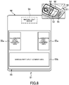
- FIG. 8 is a schematic diagram showing a comparative example for comparison with the overhead console shown in FIG. 1 to FIG. 7
- An overhead console 50 of the comparative example shown in FIG. 8 does not include a configuration corresponding to the vehicle interior checking mirror 14 of the overhead console 10 of the above-described embodiment.
- the overhead console 50 of the comparative example does not have a structure for projecting and displaying the above-described symbol G10 indicating the seatbelt warning information on the mirror surface, and instead of this, it is provided with a dedicated display screen 54 for displaying the symbol G10.
- the display screen 54 is installed in a console housing 51 at a location some distance from an illumination 52 that illuminates the vehicle interior to avoid the symbol G10 from being difficult to see due to the bright illumination 52.
- a circuit for displaying the symbol G10 on the display screen 54 needs to be located away from an illumination board 55 including an illumination light source placement area 55a and a various switches-placement area 55b.
- a warning light board 56 on which the circuit for displaying the symbol G10 is formed is provided as a separate board from the illumination board 55 and is located away from the illumination board 55.
- it is necessary to provide the warning light board 56 separately from the illumination board 55 it is difficult to downsize the overhead console 50 of the comparative example.
- the overhead console 10 of the embodiment shown in FIG. 1 to FIG. 7 can provide the following advantageous effects.
- the symbol G10 is displayed in the partial region 141a of the mirror surface 141 of the vehicle interior checking mirror 14 that is installed at a location closer to the windshield W10 than the illumination board 15 on which the illumination light source 151 is mounted. That is, since the symbol G10 is displayed at a location some distance from the illumination light source 151, it is possible to prevent a decrease in visibility of the symbol G10 due to the bright illumination.
- the mirror surface light source 16 for displaying the symbol G10 on the mirror surface 141 is mounted on the illumination board 15 together with the illumination light source 151, it is not necessary to separately provide a circuit board for displaying the symbol G10, allowing to downsize the overhead console 10.
- the overhead console 10 described above utilizes components that are originally provided in a general overhead console, such as the illumination board 15 on which the illumination light source 151 is mounted. That is, according to the above configuration, it is possible to construct the overhead console 10 having the display function without significantly changing the basic structure of a general overhead console as mentioned above.
- the vehicle interior checking mirror 14 that is used as a display unit for the symbol G10 is installed in the console housing 11 so as to be movable between the mirror surface visible position 14a and the accommodated position 14b, thus the overhead console 10 can be further downsized.
- the partial region 141a as a region for displaying the symbol G10 is a region of the mirror surface 141 of the vehicle interior checking mirror 14 in the mirror surface visible position 14a, the region being arranged along the end of the mirror surface 141 near the accommodating space 111.
- the see-through display plate 17 is provided at one wall of the walls defining the accommodating space 111 and is located close to the entrance for the vehicle interior checking mirror 14, the one wall corresponding to the facing wall facing the partial region 141a.
- the overhead console 10 can be further downsized.
- the see-through display plate 17 is capable of being switched between the display state in which the symbol G10 is transparently displayed and the blackout state in which the see-through display plate 17 is turned black, and the accommodating space 111 is defined by the inner wall faces whose color is back. According to this configuration, when the symbol G10 is not being displayed, the see-through display plate 17 in the blackout state and the inner wall face around it are reflected on the mirror surface 141 of the vehicle interior checking mirror 14, but a boundary line and such between them is desirably less visible since both of them are black.
- the blocking wall 18 for blocking stray light is provided between the mirror surface light source 16 and the see-through display plate 17. According to this configuration, the blocking wall 18 can prevent the leakage of the stray light from the overhead console 10 when the symbol G10 is being displayed.
- the illumination board 15 includes the mirror surface light source placement area 15c arranged adjacent to the illumination light source placement area 15a. According to this configuration, the mirror surface light source 16 and the illumination light source 151 are arranged in an efficient manner on the illumination board 15, thus the illumination board 15 can be downsized and this can downsize the overhead console 10.
- the embodiment described above is only a representative embodiment of the overhead console, and the overhead console is not limited thereto and can be modified and implemented in various ways.
- the symbol G10 indicating the seatbelt warning information is shown as an example of the symbol to be displayed on the mirror surface 141 of the vehicle interior checking mirror 14.
- the symbol to be displayed on the mirror surface 141 of the vehicle interior checking mirror 14 is not limited to this, and any symbol can be adopted as long as it can be transparently displayed on the see-through display plate 17.
- the vehicle interior checking mirror 14 that is installed in the console housing 11 so as to be movable between the mirror surface visible position 14a and the accommodated position 14b is shown as an example of the vehicle interior checking mirror.
- the vehicle interior checking mirror is not limited to this, and an immovable mirror may be provided integrally with the console housing as long as it is provided to a location capable of reflecting therein the symbol that has been transparently displayed on the see-through display plate.
- the vehicle interior checking mirror may be provided as a separate component at a location away from the console housing.
- the overhead console 10 can be further downsized, as described above.
- the partial region 141a arranged along the end of the mirror surface 141 near the accommodating space 111 is shown.
- the installation location of the see-through display plate it is illustrated that the see-through display plate is located on the facing wall of the walls defining the accommodating space 111 facing the partial region 141a and is located close to the entrance for the vehicle interior checking mirror 14.
- the partial region in which the symbol is displayed and the installation location for the see-through display plate are not limited to these and can be configured arbitrarily.
- the overhead console 10 can be further downsized by adopting the partial region 141a in the above-described location and by adopting the installation location for the see-through display plate 17 as described above.
- the see-through display plate 17 capable of being switched between the display state in which the symbol G10 is being displayed and the blackout state is shown.
- the accommodating space for the vehicle interior checking mirror the accommodating space 111 defined by the black inner wall faces is shown.
- the see-through display plate and the accommodating space are not limited to these.
- the see-through display plate does not need to be in the blackout state as long as the transparent display of the symbol is possible, and the inner wall faces defining the accommodating space may be in colors other than black.
- the boundary line and such between the see-through display plate 17 reflected on the mirror surface 141 and the inner wall face defining the accommodating space can be less visible when the symbol G10 is not being displayed.
- the overhead console 10 including the blocking wall 18 provided between the mirror surface light source 16 and the see-through display plate 17 is shown.
- the overhead console is not limited to this and may not include the blocking wall 18 as described above.
- the blocking wall 18 by providing the blocking wall 18, leakage of stray light can be prevented as described above.
- the illumination board 15 including the mirror surface light source placement area 15c arranged adjacent to the illumination light source placement area 15a is shown.
- the illumination board is not limited to this, and the mirror surface light source placement area and the illumination light source placement area may be provided separately from each other.
- the overhead console 10 can be downsized by providing the mirror surface light source placement area 15c adjacent to the illumination light source placement area 15a.
Landscapes
- Engineering & Computer Science (AREA)
- Mechanical Engineering (AREA)
- Multimedia (AREA)
- Automation & Control Theory (AREA)
- Chemical & Material Sciences (AREA)
- Combustion & Propulsion (AREA)
- Transportation (AREA)
- Vehicle Step Arrangements And Article Storage (AREA)
- Arrangements Of Lighting Devices For Vehicle Interiors, Mounting And Supporting Thereof, Circuits Therefore (AREA)
- Fittings On The Vehicle Exterior For Carrying Loads, And Devices For Holding Or Mounting Articles (AREA)
- Illuminated Signs And Luminous Advertising (AREA)
Description
- The present invention relates to an overhead console to be mounted on a ceiling of a vehicle interior at a location near a windshield.
- Conventionally, an overhead console that is mounted on a ceiling of a vehicle interior at a location near a windshield is known (for example, refer to Patent Document 1). In addition to an illumination light source, various operation switches and such are mounted to the overhead console.
- It is known to display a symbol indicating a seatbelt fastening state to warn a passenger in the vehicle who is not fastening his/her seatbelt, in which a display function for displaying the symbol is provided to the overhead console (for example, refer to Patent Document 2). By providing the display function as mentioned above to the overhead console, the displayed symbol can be easily seen by all passengers in the vehicle interior.
-
- Patent Document 1:
JP H11-208377 A - Patent Document 2:
JP 2011-105157 A - The overhead console described in Patent Document 2 has a problem that, when a display unit for displaying the symbol is placed too close to the illumination light source to downsize the overhead console, it could be difficult to see the symbol when the illumination light source is turned on simultaneously with the display of the symbol due to the illumination being too bright. It is thus desirable to place the display unit at a location some distance from the illumination light source. This, however, requires to provide a circuit board for the display unit separately for a mounting board for the illumination light source, making it difficult to downsize the overhead console.
- In the above explanation, the symbol indicating the seatbelt fastening state was given as one example of a symbol to be displayed by the display function provided on the overhead console, and the problem that there is difficulty in downsizing the overhead console has been explained. This problem, however, could occur in providing the display function in the overhead console regardless of a specific symbol to be displayed by the display function.
- In view of this, an object of the present invention is to provide an overhead console that includes a display function and that can be downsized.
- In order to achieve the above-described object, the present invention provides, in one aspect, an overhead console including a console housing attachable to a ceiling of a vehicle interior at a location near a windshield, an illumination board on which an illumination light source is mounted and which is accommodated in the console housing, a vehicle interior checking mirror installed at a location closer to the windshield than the illumination board and arranged capable of being in a mirror surface visible position in which a mirror surface is visually recognizable by a passenger, a mirror surface light source that is mounted on the illumination board together with the illumination light source and that is configured to emit light toward the mirror surface of the vehicle interior checking mirror in the mirror surface visible position, and a see-through display plate that is a display plate capable of transparently displaying a symbol indicating predetermined information, wherein the see-through display plate is provided in the console housing at a location between the mirror surface light source and the mirror surface so as not to hinder the passenger from visually recognizing the mirror surface and so as to face a partial region of the mirror surface, and wherein the see-through display plate is configured to allow light from the mirror surface light source to transmit therethrough to display the symbol on the partial region of the mirror surface.
- According to the overhead console described above, the symbol is displayed in the partial region of the mirror surface of the vehicle interior checking mirror installed at a location closer to the windshield than the illumination board on which the illumination light source is mounted. That is, the symbol is displayed at a location some distance from the illumination light source, thus it is possible to prevent a decrease in the visibility of the symbol due to bright illumination. In addition to that, the mirror surface light source for displaying the symbol on the mirror surface is mounted on the illumination board together with the illumination light source, thus there is no need to separately provide a circuit board for displaying the symbol, allowing to downsize the overhead console.
-
-
FIG. 1 is an external perspective view of a vehicle interior of a motor vehicle to which an overhead console according to one embodiment is applied; -
FIG. 2 is an external perspective view of a surface of the overhead console shown inFIG. 1 which can be seen when looking up from a seat; -
FIG. 3 is a schematic diagram showing how a vehicle interior checking mirror shown inFIG. 1 which is in a mirror surface visible position is used to provide a seatbelt warning to a passenger in a rear seat; -
FIG. 4 is a cross sectional view taken along a line V11-V11 inFIG. 2 showing an internal structure of the overhead console ofFIG. 1 to FIG. 3 ; -
FIG. 5 is a schematic component placement diagram showing an arrangement of a light source and a switch on an illumination board shown inFIG. 4 ; -
FIG. 6 is a schematic block diagram schematically showing a circuit structure of the illumination board shown inFIG. 4 ; -
FIG. 7 is a schematic diagram showing how transparent display of a symbol is performed on a see-through display plate shown inFIG. 4 ; and -
FIG. 8 is a schematic diagram showing a comparative example for comparison with the overhead console shown inFIG. 1 to FIG. 7 . - One embodiment of an overhead console of the present invention will be described with reference to the drawings.
-
FIG. 1 is an external perspective view of a vehicle interior of a motor vehicle to which an overhead console according to one embodiment is applied.FIG. 2 is an external perspective view of a surface of the overhead console shown inFIG. 1 which can be seen when looking up from a seat. - An
overhead console 10 of this embodiment is a device configured to be attached to a ceiling R10 of a vehicle interior C10 at a location near a windshield W10. Theoverhead console 10 includes aconsole housing 11, anillumination 12, aswitch 13 for turning on the illumination, and a vehicle interior checking mirror 14. Theconsole housing 11 is a resin housing attached to the ceiling R10 of the vehicle interior C10 near the windshield W10. Theilluminations 12 are provided on the right and left sides in a pair, and are configured to illuminate the vehicle interior C10 with light from a later-described illumination light source. A vehicle interior checking mirror 14 is a mirror installed in a manner capable of being in a mirror surface visible position 14a in which amirror surface 141 is visually recognizable by a passenger. In this embodiment, anaccommodating space 111 for accommodating the vehicle interior checking mirror 14 is provided inside theconsole housing 11. The vehicle interior checking mirror 14 is installed to theconsole housing 11 so as to be movable along an arrow D11 between the mirror surface visible position 14a and an accommodated position 14b in which the vehicle interior checking mirror 14 is accommodated in theaccommodating space 111. The vehicle interior checking mirror 14 is provided with amovement switch 143 for moving the vehicle interior checking mirror 14 to the mirror surface visible position 14a, themovement switch 143 being disposed on abottom face 142a of amirror housing 142 which is flush with a surface of theconsole housing 11 in the accommodated position 14b. When themovement switch 143 is pressed as shown by an arrow D12 inFIG. 1 , the vehicle interior checking mirror 14 is moved from the accommodated position 14b to the mirror surface visible position 14a. - In this embodiment, the vehicle interior checking mirror 14 in the mirror surface visible position 14a is used not only for checking the vehicle interior, but also for providing a seatbelt warning to a passenger in the rear seat, the seatbelt warning being a warning related to fastening of a seatbelt.
-
FIG. 3 is a schematic diagram showing how the vehicle interior checking mirror shown inFIG. 1 which is in the mirror surface visible position is used to provide the seatbelt warning to a passenger in the rear seat. - First, in the
overhead console 10 of this embodiment, themirror surface 141 of the vehicle interior checking mirror 14 has a curved surface such that it is visible to all passengers including a passenger in the rear seat, a passenger in a front passenger's seat and a driver. In the case where there is a passenger in the rear seat who is not fastening the seatbelt, a symbol G10 indicating predetermined warning information to warn and urge this passenger to fasten the seatbelt is displayed. This symbol G10 is displayed in apartial region 141a of the vehicle interiorchecking mirror surface 141 in the mirror surface visible position 14a, thepartial region 141a being arranged along an end of the vehicle interiorchecking mirror surface 141 near theaccommodating space 111 of theconsole housing 11. The symbols G10 are provided so as to form pairs with the three rear seats, respectively, and the symbol G10 that corresponds to the rear seat in which a passenger who is not fastening the seatbelt is seated is to be displayed in thepartial region 141a of themirror surface 141.FIG. 3 shows an example in which passengers in all of the three rear seats are not fastening their seatbelts, thus all of the three symbols G10 are being displayed. - The
overhead console 10 of this embodiment is configured as explained below to display the warning symbol G10 described above. -
FIG. 4 is a cross sectional view taken along a line V11-V11 inFIG. 2 showing an internal structure of the overhead console ofFIG. 1 to FIG. 3 . InFIG. 4 , the internal structure of theoverhead console 10 is shown in cross section for two cases, namely, the case where the vehicle interior checking mirror 14 is in the accommodated position 14b, and the case where the vehicle interior checking mirror 14 is in the mirror surface visible position 14a. - The
overhead console 10 of this embodiment includes theconsole housing 11, theillumination 12, theswitch 13, the vehicle interior checking mirror 14, theillumination board 15, a mirrorsurface light source 16, a see-throughdisplay plate 17, and ablocking wall 18. - As described above, the
console housing 11 is attached to the ceiling R10 of the vehicle interior C10 near the windshield W10. Theconsole housing 11 is formed in a flat rectangular box shape, and theaccommodating space 111 for accommodating the vehicle interior checking mirror 14 is provided inside theconsole housing 11 at a location closer to the windshield W10 than theillumination board 15. - The
illumination 12 is configured to illuminate the vehicle interior C10 with light from anillumination light source 151, and has alight guide part 121 for guiding the light from theillumination light source 151 while diffusing said light. - The
switch 13 is configured to be operated to, for example, turn on and off theillumination 12 and to activate and deactivate the display function for displaying the above-described symbol G10 to provide the seatbelt warning. - The vehicle interior checking mirror 14 is installed at a location closer to the windshield W10 than the
illumination board 15 and is arranged capable of being in the mirror surface visible position 14a in which themirror surface 141 is visually recognizable by a passenger. In this embodiment, the vehicle interior checking mirror 14 is installed in theconsole housing 11 so as to be movable between the mirror surface visible position 14a and the accommodated position 14b in which the vehicle interior checking mirror 14 is accommodated in theaccommodating space 111. In order to enable such movement, the vehicle interior checking mirror 14 has amirror housing 142 having a fan-shaped cross section and is installed in theconsole housing 11 so as to be rotatable around arotation shaft 145 that penetrates a pivot point of the fan. Themirror surface 141 is formed at an arc portion of the fan, and, by rotating the vehicle interior checking mirror 14 around therotation shaft 145, themirror surface 141 protrudes from theaccommodating space 111 and is retracted in theaccommodating space 111 such that abottom face 142a of themirror housing 142 is flush with the surface of theconsole housing 11. This movement of the vehicle interior checking mirror 14 is performed by adrive mechanism 144 having apinion gear 144a and arack gear 144b provided on themirror surface 141 side. - The
illumination board 15 is a flat-plate shaped circuit board on which theillumination light source 151 and theswitch 13 are mounted and which is accommodated in theconsole housing 11. Inside theconsole housing 11, theillumination board 15 is arranged along the ceiling R10 of the vehicle interior C10. - The mirror
surface light source 16 is a light source which is mounted on theillumination board 15 together with theillumination light source 151 and theswitch 13, and which is configured to emit light toward themirror surface 141 of the vehicle interior checking mirror 14 in the mirror surface visible position 14a to display the above-described warning symbol G10. -
FIG. 5 is a schematic component placement diagram showing an arrangement of the light source and the switch on the illumination board shown inFIG. 4 .FIG. 6 is a schematic block diagram schematically showing the circuit structure of the illumination board shown inFIG. 4 - On the
illumination board 15, areas for placing various components are provided on a surface thereof on the side of a floor of the vehicle interior C10 opposite to the ceiling R10. Specifically, as shown inFIG. 5 , a various switches-placement area 15b is provided to an area of theconsole housing 11 of theoverhead console 10 located on the opposite side of theaccommodating space 111 for the vehicle interior checking mirror 14. As shown inFIG. 6 , the various switches-placement area 15b is mounted with a switch 13a for a rightillumination light source 151a of theillumination light source 151 and aswitch 13b for a left illuminationlight source 151b of theillumination light source 151. Further, the various switches-placement area 15b is mounted with aswitch 13c for permitting opening and closing of a door, aswitch 13d for turning on at once all the illumination lamps in the vehicle interior C10, and aswitch 13e for activating the display function of the warning symbol G10. - Further, on the
illumination board 15, a pair of right and left illumination lightsource placement areas 15a is provided on theaccommodating space 111 side with a gap between each other, the illumination lightsource placement areas 15a being arranged for placing the pair of right and left illuminationlight sources 151. Further, a light source for illuminatingswitch 152 that illuminates each switch when an ignition key is turned is also placed within the pair of illumination lightsource placement areas 15a. A mirror surface lightsource placement area 15c for placing the mirrorsurface light source 16 is provided between each of the pair of illumination lightsource placement areas 15a. In an area on theaccommodating space 111 side including these three areas, there is provided anillumination control circuit 153 configured to control turn on and off of theillumination light source 151 and of the mirrorsurface light source 16. A part of theillumination control circuit 153 is awarning light circuit 161 configured to control turn on and off of the mirrorsurface light source 16 to display the warning symbol G10. Theillumination control circuit 153 is connected to a BCM (Body Control Module) 20 which is a module installed outside theoverhead console 10 for integrating functions of various lights and a door lock function and such. - The
illumination board 15 on which theillumination light source 151 and the mirrorsurface light source 16 are mounted has been explained above, and now, referring back toFIG. 4 , other components of theoverhead console 10 will be explained below. - The see-through
display plate 17 in theoverhead console 10 is located in theconsole housing 11 between the mirrorsurface light source 16 and themirror surface 141 so as not to hinder a passenger from visually recognizing themirror surface 141 and so as to face thepartial region 141a of themirror surface 141. This see-throughdisplay plate 17 is a display plate capable of transparently displaying the above-described symbol G10 indicating the seatbelt warning information. That is, the see-throughdisplay plate 17 allows the light from the mirrorsurface light source 16 to transmit therethrough to display the symbol G10 in thepartial region 141a of themirror surface 141. - The
partial region 141a of themirror surface 141 is a region of themirror surface 141 of the vehicle interior checking mirror 14 along an end of themirror surface 141 near theaccommodating space 111, with the vehicle interior checking mirror 14 in the mirror surface visible position 14a and projecting out from theaccommodating space 111. The see-throughdisplay plate 17 is provided at one wall of walls defining theaccommodating space 111 and is located close to an entrance for the vehicle interior checking mirror 14, the one wall corresponding to a facing wall facing thepartial region 141a of themirror surface 141 of the vehicle interior checking mirror 14 in the mirror surface visible position 14a. - On the see-through
display plate 17, transparent display (i.e., see-through display) of the symbol G10 is performed as follows. -
FIG. 7 is a schematic diagram showing how the transparent display of the symbol is performed on the see-through display plate shown inFIG. 4 . - The see-through
display plate 17 is capable of being switched between a display state in which the symbol G10 is transparently displayed, and a blackout state in which the see-throughdisplay plate 17 is turned black. This switching of the states is performed by a passenger by operating theswitch 13e shown inFIG. 6 that is configured to activate the display function of displaying the warning symbol G10. When theswitch 13e is turned on, the symbol G10 is transparently displayed on the see-throughdisplay plate 17 according to the seatbelt fastening state, and the mirrorsurface light source 16 is turned on. The light of the mirrorsurface light source 16 is transmitted through the see-throughdisplay plate 17, and the symbol according to the seatbelt fastening state that is being transparently displayed on the see-throughdisplay plate 17 is projected and displayed on thepartial region 141a of themirror surface 141. The image projected onto thepartial region 141a of themirror surface 141 is reflected by themirror surface 141 and is directed toward a passenger's eye point, thereby the symbol G10 is visually recognized by the passenger. If there is no passenger who is not fastening the seatbelt, then no symbol G10 is transparently displayed even when the see-throughdisplay plate 17 is not in the blackout state. In this case, thepartial region 141a of themirror surface 141 is just irradiated with the light of the mirrorsurface light source 16, and the symbol G10 is not visually recognized by the passenger. - On the other hand, when the
switch 13e for the display function of displaying the symbol G10 is turned off, then the see-throughdisplay plate 17 is in the blackout state. At this time, the blackened see-throughdisplay plate 17 is reflected on thepartial region 141a of themirror surface 141 together with other inner wall faces defining theaccommodating space 111. In this embodiment, theaccommodating space 111 is defined by inner wall faces whose color is black. Thus, the blackened see-throughdisplay plate 17 and the black colored inner wall faces are reflected on thepartial region 141a of themirror surface 141 forming a black band shape. - Further, the
overhead console 10 of this embodiment is provided with a blockingwall 18 as shown inFIG. 4 . The blockingwall 18 is provided between the mirrorsurface light source 16 and the see-throughdisplay plate 17, and is a part that blocks stray light traveling from the mirrorsurface light source 16 to directions other than a direction toward the see-throughdisplay plate 17. - The
overhead console 10 described above can provide advantageous effects as described below. However, before describing them, a comparative example for comparison with thisoverhead console 10 will be described. -
FIG. 8 is a schematic diagram showing a comparative example for comparison with the overhead console shown inFIG. 1 to FIG. 7 - An
overhead console 50 of the comparative example shown inFIG. 8 does not include a configuration corresponding to the vehicle interior checking mirror 14 of theoverhead console 10 of the above-described embodiment. Thus, theoverhead console 50 of the comparative example does not have a structure for projecting and displaying the above-described symbol G10 indicating the seatbelt warning information on the mirror surface, and instead of this, it is provided with adedicated display screen 54 for displaying the symbol G10. Thedisplay screen 54 is installed in aconsole housing 51 at a location some distance from anillumination 52 that illuminates the vehicle interior to avoid the symbol G10 from being difficult to see due to thebright illumination 52. Thus, in theoverhead console 50 of the comparative example, a circuit for displaying the symbol G10 on thedisplay screen 54 needs to be located away from anillumination board 55 including an illumination lightsource placement area 55a and a various switches-placement area 55b. For this reason, in theoverhead console 50 of the comparative example, a warninglight board 56 on which the circuit for displaying the symbol G10 is formed is provided as a separate board from theillumination board 55 and is located away from theillumination board 55. Thus, since it is necessary to provide thewarning light board 56 separately from theillumination board 55, it is difficult to downsize theoverhead console 50 of the comparative example. - In contrast to this comparative example, the
overhead console 10 of the embodiment shown inFIG. 1 to FIG. 7 can provide the following advantageous effects. First, according to theoverhead console 10, the symbol G10 is displayed in thepartial region 141a of themirror surface 141 of the vehicle interior checking mirror 14 that is installed at a location closer to the windshield W10 than theillumination board 15 on which theillumination light source 151 is mounted. That is, since the symbol G10 is displayed at a location some distance from theillumination light source 151, it is possible to prevent a decrease in visibility of the symbol G10 due to the bright illumination. In addition to that, since the mirrorsurface light source 16 for displaying the symbol G10 on themirror surface 141 is mounted on theillumination board 15 together with theillumination light source 151, it is not necessary to separately provide a circuit board for displaying the symbol G10, allowing to downsize theoverhead console 10. - Further, the
overhead console 10 described above utilizes components that are originally provided in a general overhead console, such as theillumination board 15 on which theillumination light source 151 is mounted. That is, according to the above configuration, it is possible to construct theoverhead console 10 having the display function without significantly changing the basic structure of a general overhead console as mentioned above. - In this embodiment, the vehicle interior checking mirror 14 that is used as a display unit for the symbol G10 is installed in the
console housing 11 so as to be movable between the mirror surface visible position 14a and the accommodated position 14b, thus theoverhead console 10 can be further downsized. - Moreover, in this embodiment, the
partial region 141a as a region for displaying the symbol G10 is a region of themirror surface 141 of the vehicle interior checking mirror 14 in the mirror surface visible position 14a, the region being arranged along the end of themirror surface 141 near theaccommodating space 111. Further, the see-throughdisplay plate 17 is provided at one wall of the walls defining theaccommodating space 111 and is located close to the entrance for the vehicle interior checking mirror 14, the one wall corresponding to the facing wall facing thepartial region 141a. According to this configuration, since the wall defining theaccommodating space 111 for the vehicle interior checking mirror 14 is used as a region for installing the see-throughdisplay plate 17, it is not necessary to separately provide a region for installing the see-throughdisplay plate 17, and in this respect also, theoverhead console 10 can be further downsized. - Further, in this embodiment, the see-through
display plate 17 is capable of being switched between the display state in which the symbol G10 is transparently displayed and the blackout state in which the see-throughdisplay plate 17 is turned black, and theaccommodating space 111 is defined by the inner wall faces whose color is back. According to this configuration, when the symbol G10 is not being displayed, the see-throughdisplay plate 17 in the blackout state and the inner wall face around it are reflected on themirror surface 141 of the vehicle interior checking mirror 14, but a boundary line and such between them is desirably less visible since both of them are black. - Further, in this embodiment, the blocking
wall 18 for blocking stray light is provided between the mirrorsurface light source 16 and the see-throughdisplay plate 17. According to this configuration, the blockingwall 18 can prevent the leakage of the stray light from theoverhead console 10 when the symbol G10 is being displayed. - Further, in this embodiment, the
illumination board 15 includes the mirror surface lightsource placement area 15c arranged adjacent to the illumination lightsource placement area 15a. According to this configuration, the mirrorsurface light source 16 and theillumination light source 151 are arranged in an efficient manner on theillumination board 15, thus theillumination board 15 can be downsized and this can downsize theoverhead console 10. - It should be noted that the embodiment described above is only a representative embodiment of the overhead console, and the overhead console is not limited thereto and can be modified and implemented in various ways.
- For example, in the above-described embodiment, the symbol G10 indicating the seatbelt warning information is shown as an example of the symbol to be displayed on the
mirror surface 141 of the vehicle interior checking mirror 14. However, the symbol to be displayed on themirror surface 141 of the vehicle interior checking mirror 14 is not limited to this, and any symbol can be adopted as long as it can be transparently displayed on the see-throughdisplay plate 17. - Further, in the above-described embodiment, the vehicle interior checking mirror 14 that is installed in the
console housing 11 so as to be movable between the mirror surface visible position 14a and the accommodated position 14b is shown as an example of the vehicle interior checking mirror. However, the vehicle interior checking mirror is not limited to this, and an immovable mirror may be provided integrally with the console housing as long as it is provided to a location capable of reflecting therein the symbol that has been transparently displayed on the see-through display plate. Alternatively, the vehicle interior checking mirror may be provided as a separate component at a location away from the console housing. However, by installing the movable vehicle interior checking mirror 14 in theconsole housing 11, theoverhead console 10 can be further downsized, as described above. - Moreover, in the above-described embodiment, as an example of the partial region in which the symbol is displayed, the
partial region 141a arranged along the end of themirror surface 141 near theaccommodating space 111 is shown. Further, as an example of the installation location of the see-through display plate, it is illustrated that the see-through display plate is located on the facing wall of the walls defining theaccommodating space 111 facing thepartial region 141a and is located close to the entrance for the vehicle interior checking mirror 14. However, the partial region in which the symbol is displayed and the installation location for the see-through display plate are not limited to these and can be configured arbitrarily. However, as described above, theoverhead console 10 can be further downsized by adopting thepartial region 141a in the above-described location and by adopting the installation location for the see-throughdisplay plate 17 as described above. - Further, in the above-described embodiment, as an example of the see-through display plate, the see-through
display plate 17 capable of being switched between the display state in which the symbol G10 is being displayed and the blackout state is shown. Further, as an example of the accommodating space for the vehicle interior checking mirror, theaccommodating space 111 defined by the black inner wall faces is shown. However, the see-through display plate and the accommodating space are not limited to these. The see-through display plate does not need to be in the blackout state as long as the transparent display of the symbol is possible, and the inner wall faces defining the accommodating space may be in colors other than black. However, as described above, with the see-throughdisplay plate 17 capable of being switched between the states and with the inner wall faces defining the accommodating space colored in black, the boundary line and such between the see-throughdisplay plate 17 reflected on themirror surface 141 and the inner wall face defining the accommodating space can be less visible when the symbol G10 is not being displayed. - Further, in the above-described embodiment, as an example of the overhead console, the
overhead console 10 including the blockingwall 18 provided between the mirrorsurface light source 16 and the see-throughdisplay plate 17 is shown. However, the overhead console is not limited to this and may not include the blockingwall 18 as described above. However, by providing the blockingwall 18, leakage of stray light can be prevented as described above. - Further, in the above-described embodiment, as an example of the illumination board, the
illumination board 15 including the mirror surface lightsource placement area 15c arranged adjacent to the illumination lightsource placement area 15a is shown. However, the illumination board is not limited to this, and the mirror surface light source placement area and the illumination light source placement area may be provided separately from each other. However, as described above, theoverhead console 10 can be downsized by providing the mirror surface lightsource placement area 15c adjacent to the illumination lightsource placement area 15a. -
- 10
- overhead console
- 11
- console housing
- 12
- illumination
- 13, 13a, 13b, 13c, 13d, 13e
- switch
- 14
- vehicle interior checking mirror
- 14a
- mirror surface visible position
- 14b
- accommodated position
- 15
- illumination board
- 15a
- illumination light source placement area
- 15b
- various switches-placement area
- 15c
- mirror surface light source placement area
- 16
- mirror surface light source
- 17
- see-through display plate
- 18
- blocking wall
- 20
- BCM (Body Control Module)
- 111
- accommodating space
- 121
- light guide part
- 141
- mirror surface
- 142
- mirror housing
- 142a
- bottom face
- 143
- movement switch
- 144
- drive mechanism
- 144a
- pinion gear
- 144b
- rack gear
- 145
- rotation shaft
- 151, 151a, 151b
- illumination light source
- 152
- light source for illuminating switch
- 153
- illumination control circuit
- 161
- warning light circuit
- C10
- vehicle interior
- G10
- symbol
- R10
- ceiling
- W10
- windshield
Claims (6)
- An overhead console (10) comprising:a console housing (11) attachable to a ceiling (R10) of a vehicle interior at a location near a windshield (W10);an illumination board (15) on which an illumination light source (151) is mounted and which is accommodated in the console housing (11);a vehicle interior checking mirror (14) installed at a location closer to the windshield (W10) than the illumination board (15) and arranged capable of being in a mirror surface visible position (14a) in which a mirror surface (141) is visually recognizable by a passenger;characterized in thata mirror surface light source (16) that is mounted on the illumination board (15) together with the illumination light source (151) and that is configured to emit light toward the mirror surface (141) of the vehicle interior checking mirror (14) in the mirror surface visible position (14a); anda see-through display plate (17) that is a display plate capable of transparently displaying a symbol (G10) indicating predetermined information,wherein the see-through display plate (17) is provided in the console housing (11) at a location between the mirror surface light source (16) and the mirror surface (141) so as not to hinder the passenger from visually recognizing the mirror surface (141) and so as to face a partial region (141a) of the mirror surface (141), andwherein the see-through display plate (17) is configured to allow light from the mirror surface light source (16) to transmit therethrough to display the symbol (G10) on the partial region (141a) of the mirror surface (141).
- The overhead console (10) according to claim 1, wherein an accommodating space (111) for the vehicle interior checking mirror (14) is provided inside the console housing (11) at a location closer to the windshield (W10) than the illumination board (15), and
wherein the vehicle interior checking mirror (14) is installed at the console housing (11) so as to be movable between the mirror surface visible position (14a) and an accommodated position (14b) in which the vehicle interior checking mirror (14) is accommodated in the accommodating space (111). - The overhead console (10) according to claim 2, wherein the partial region is a region (141a) of the mirror surface (141) of the vehicle interior checking mirror (14) in the mirror surface visible position (14a) in which the vehicle interior checking mirror (14) projects out from the accommodating space (111), the partial region (141a) being arranged along an end of the mirror surface (141) near the accommodating space (111), and
wherein the see-through display plate (17) is provided at one wall of walls defining the accommodating space (111) and is located close to an entrance for the vehicle interior checking mirror (14), the one wall corresponding to a facing wall facing the partial region (141a) of the mirror surface (141) of the vehicle interior checking mirror (14) that is in the mirror surface visible position (14a). - The overhead console (10) according to claim 2 or 3, wherein the see-through display plate (17) is capable of being switched between a display state in which the symbol (G10) is transparently displayed, and a blackout state in which the see-through display plate (17) is turned black, and
wherein the accommodating space (111) is defined by inner wall faces whose color is black. - The overhead console (10) according to any one of claims 1 to 4, further comprising a blocking wall (18) provided between the mirror surface light source (16) and the see-through display plate (17),
wherein the blocking wall (18) blocks stray light traveling from the mirror surface light source (16) to directions other than a direction toward the see-through display plate (17). - The overhead console (10) according to any one of claims 1 to 5, wherein the illumination board (15) is provided with a placement area (15c) for the mirror surface light source (16) arranged adjacent to a placement area (15a) for the illumination light source (151).
Applications Claiming Priority (1)
| Application Number | Priority Date | Filing Date | Title |
|---|---|---|---|
| JP2020104269A JP7119026B2 (en) | 2020-06-17 | 2020-06-17 | overhead console |
Publications (2)
| Publication Number | Publication Date |
|---|---|
| EP3925828A1 EP3925828A1 (en) | 2021-12-22 |
| EP3925828B1 true EP3925828B1 (en) | 2022-04-27 |
Family
ID=76059735
Family Applications (1)
| Application Number | Title | Priority Date | Filing Date |
|---|---|---|---|
| EP21175264.7A Active EP3925828B1 (en) | 2020-06-17 | 2021-05-21 | Overhead console |
Country Status (4)
| Country | Link |
|---|---|
| US (1) | US11458898B2 (en) |
| EP (1) | EP3925828B1 (en) |
| JP (1) | JP7119026B2 (en) |
| CN (1) | CN113799726B (en) |
Family Cites Families (19)
| Publication number | Priority date | Publication date | Assignee | Title |
|---|---|---|---|---|
| JPH01208377A (en) | 1988-02-12 | 1989-08-22 | Nippon Steel Corp | Carbonaceous material for cultivating organism |
| JPH0313242U (en) * | 1989-06-27 | 1991-02-12 | ||
| DE4334855A1 (en) * | 1993-10-13 | 1995-04-20 | Bosch Gmbh Robert | Display device for motor vehicles |
| JPH11208377A (en) | 1998-01-22 | 1999-08-03 | Harness Syst Tech Res Ltd | Overhead console |
| DE60028907T2 (en) * | 1999-11-24 | 2007-02-15 | Donnelly Corp., Holland | Rearview mirror with utility function |
| JP2003226156A (en) | 2002-02-05 | 2003-08-12 | Denso Corp | Display device for vehicles |
| JP3952474B2 (en) * | 2003-12-22 | 2007-08-01 | 本田技研工業株式会社 | Overhead console device |
| JP2006142892A (en) * | 2004-11-17 | 2006-06-08 | Imasen Electric Ind Co Ltd | Overhead console |
| JP4930315B2 (en) * | 2007-01-19 | 2012-05-16 | 株式会社デンソー | In-vehicle information display device and light irradiation device used therefor |
| JP4376272B2 (en) | 2007-02-23 | 2009-12-02 | 小島プレス工業株式会社 | Overhead console device |
| FR2914243A1 (en) * | 2007-03-30 | 2008-10-03 | Cml Innovative Technologies So | RANGE-GLASSES IN ROOF CONSOLE. |
| US20080252090A1 (en) * | 2007-04-16 | 2008-10-16 | Lear Corporation | Vehicle overhead console assembly having a drop down occupant mirror assembly |
| JP2011105157A (en) | 2009-11-18 | 2011-06-02 | Kojima Press Industry Co Ltd | Seat belt wearing warning device |
| CN105026211B (en) * | 2013-01-11 | 2018-02-02 | 江森自控科技公司 | Slim overhead console |
| KR101575477B1 (en) * | 2014-05-23 | 2015-12-07 | 현대자동차주식회사 | Control method for button symbol of inside mirror |
| US9073494B1 (en) * | 2014-06-04 | 2015-07-07 | Ford Global Technologies, Llc | Vehicle interior conversation mirror assembly |
| DE102016113120A1 (en) * | 2015-07-27 | 2017-02-02 | Ford Global Technologies, Llc | Sitzgurtbeleuchtungssystem |
| CA2976543C (en) * | 2016-08-23 | 2026-02-10 | Vijyat Bhalla | System and method for augmented reality head up display for vehicles |
| JP2019001296A (en) * | 2017-06-15 | 2019-01-10 | 矢崎総業株式会社 | Interior lighting |
-
2020
- 2020-06-17 JP JP2020104269A patent/JP7119026B2/en active Active
-
2021
- 2021-05-21 US US17/326,635 patent/US11458898B2/en active Active
- 2021-05-21 EP EP21175264.7A patent/EP3925828B1/en active Active
- 2021-06-17 CN CN202110670040.7A patent/CN113799726B/en active Active
Also Published As
| Publication number | Publication date |
|---|---|
| CN113799726B (en) | 2024-02-02 |
| EP3925828A1 (en) | 2021-12-22 |
| CN113799726A (en) | 2021-12-17 |
| JP7119026B2 (en) | 2022-08-16 |
| US11458898B2 (en) | 2022-10-04 |
| JP2021195065A (en) | 2021-12-27 |
| US20210394679A1 (en) | 2021-12-23 |
Similar Documents
| Publication | Publication Date | Title |
|---|---|---|
| EP1625971B1 (en) | Vehicle interior illumination structure | |
| US8235460B2 (en) | Vehicle window assembly | |
| US20120104789A1 (en) | Vehicle window assembly | |
| CN109693620A (en) | Vehicular photographic arrangement | |
| JP2004090897A (en) | Illumination device for vehicles | |
| JP4737241B2 (en) | Lighting device in the passenger compartment | |
| JP4802980B2 (en) | Display device | |
| JP4930719B2 (en) | In-vehicle electronic device operation device | |
| CN120882600A (en) | Lighting equipment on vehicle doors | |
| EP3925828B1 (en) | Overhead console | |
| JP4448744B2 (en) | Lighting device in the passenger compartment | |
| KR101561399B1 (en) | Display device for a vehicle | |
| JP4407455B2 (en) | Lighting device in the passenger compartment | |
| EP3228501B1 (en) | Lighting device for an outer cover on a side of a vehicle | |
| JP2008051970A (en) | Head-up display device for vehicle | |
| JP2006076557A (en) | Lighting device in the passenger compartment | |
| JP2022013722A (en) | Vehicle lamp unit | |
| JP5211565B2 (en) | Vehicle instrument | |
| JP2007184174A (en) | Switch structure | |
| JP7695612B2 (en) | Head-up display device and lighting structure using the same | |
| JPH01289725A (en) | Display for vehicle | |
| JP5029521B2 (en) | Vehicle display device | |
| JP4179956B2 (en) | Car operation panel | |
| KR960003202Y1 (en) | Vehicle status indicator | |
| JPH0526555Y2 (en) |
Legal Events
| Date | Code | Title | Description |
|---|---|---|---|
| PUAI | Public reference made under article 153(3) epc to a published international application that has entered the european phase |
Free format text: ORIGINAL CODE: 0009012 |
|
| STAA | Information on the status of an ep patent application or granted ep patent |
Free format text: STATUS: REQUEST FOR EXAMINATION WAS MADE |
|
| 17P | Request for examination filed |
Effective date: 20210521 |
|
| AK | Designated contracting states |
Kind code of ref document: A1 Designated state(s): AL AT BE BG CH CY CZ DE DK EE ES FI FR GB GR HR HU IE IS IT LI LT LU LV MC MK MT NL NO PL PT RO RS SE SI SK SM TR |
|
| B565 | Issuance of search results under rule 164(2) epc |
Effective date: 20210818 |
|
| GRAP | Despatch of communication of intention to grant a patent |
Free format text: ORIGINAL CODE: EPIDOSNIGR1 |
|
| STAA | Information on the status of an ep patent application or granted ep patent |
Free format text: STATUS: GRANT OF PATENT IS INTENDED |
|
| RBV | Designated contracting states (corrected) |
Designated state(s): AL AT BE BG CH CY CZ DE DK EE ES FI FR GB GR HR HU IE IS IT LI LT LU LV MC MK MT NL NO PL PT RO RS SE SI SK SM TR |
|
| RIC1 | Information provided on ipc code assigned before grant |
Ipc: B60R 11/00 20060101ALN20220111BHEP Ipc: B60R 22/48 20060101ALN20220111BHEP Ipc: B60R 1/00 20060101AFI20220111BHEP |
|
| INTG | Intention to grant announced |
Effective date: 20220211 |
|
| RIC1 | Information provided on ipc code assigned before grant |
Ipc: B60R 11/00 20060101ALN20220128BHEP Ipc: B60R 22/48 20060101ALN20220128BHEP Ipc: B60R 1/00 20060101AFI20220128BHEP |
|
| GRAS | Grant fee paid |
Free format text: ORIGINAL CODE: EPIDOSNIGR3 |
|
| GRAA | (expected) grant |
Free format text: ORIGINAL CODE: 0009210 |
|
| STAA | Information on the status of an ep patent application or granted ep patent |
Free format text: STATUS: THE PATENT HAS BEEN GRANTED |
|
| AK | Designated contracting states |
Kind code of ref document: B1 Designated state(s): AL AT BE BG CH CY CZ DE DK EE ES FI FR GB GR HR HU IE IS IT LI LT LU LV MC MK MT NL NO PL PT RO RS SE SI SK SM TR |
|
| REG | Reference to a national code |
Ref country code: GB Ref legal event code: FG4D |
|
| REG | Reference to a national code |
Ref country code: CH Ref legal event code: EP |
|
| REG | Reference to a national code |
Ref country code: DE Ref legal event code: R096 Ref document number: 602021000076 Country of ref document: DE |
|
| REG | Reference to a national code |
Ref country code: AT Ref legal event code: REF Ref document number: 1486710 Country of ref document: AT Kind code of ref document: T Effective date: 20220515 |
|
| REG | Reference to a national code |
Ref country code: IE Ref legal event code: FG4D |
|
| REG | Reference to a national code |
Ref country code: LT Ref legal event code: MG9D |
|
| REG | Reference to a national code |
Ref country code: NL Ref legal event code: MP Effective date: 20220427 |
|
| REG | Reference to a national code |
Ref country code: AT Ref legal event code: MK05 Ref document number: 1486710 Country of ref document: AT Kind code of ref document: T Effective date: 20220427 |
|
| PG25 | Lapsed in a contracting state [announced via postgrant information from national office to epo] |
Ref country code: NL Free format text: LAPSE BECAUSE OF FAILURE TO SUBMIT A TRANSLATION OF THE DESCRIPTION OR TO PAY THE FEE WITHIN THE PRESCRIBED TIME-LIMIT Effective date: 20220427 |
|
| PG25 | Lapsed in a contracting state [announced via postgrant information from national office to epo] |
Ref country code: SE Free format text: LAPSE BECAUSE OF FAILURE TO SUBMIT A TRANSLATION OF THE DESCRIPTION OR TO PAY THE FEE WITHIN THE PRESCRIBED TIME-LIMIT Effective date: 20220427 Ref country code: PT Free format text: LAPSE BECAUSE OF FAILURE TO SUBMIT A TRANSLATION OF THE DESCRIPTION OR TO PAY THE FEE WITHIN THE PRESCRIBED TIME-LIMIT Effective date: 20220829 Ref country code: NO Free format text: LAPSE BECAUSE OF FAILURE TO SUBMIT A TRANSLATION OF THE DESCRIPTION OR TO PAY THE FEE WITHIN THE PRESCRIBED TIME-LIMIT Effective date: 20220727 Ref country code: LT Free format text: LAPSE BECAUSE OF FAILURE TO SUBMIT A TRANSLATION OF THE DESCRIPTION OR TO PAY THE FEE WITHIN THE PRESCRIBED TIME-LIMIT Effective date: 20220427 Ref country code: HR Free format text: LAPSE BECAUSE OF FAILURE TO SUBMIT A TRANSLATION OF THE DESCRIPTION OR TO PAY THE FEE WITHIN THE PRESCRIBED TIME-LIMIT Effective date: 20220427 Ref country code: GR Free format text: LAPSE BECAUSE OF FAILURE TO SUBMIT A TRANSLATION OF THE DESCRIPTION OR TO PAY THE FEE WITHIN THE PRESCRIBED TIME-LIMIT Effective date: 20220728 Ref country code: FI Free format text: LAPSE BECAUSE OF FAILURE TO SUBMIT A TRANSLATION OF THE DESCRIPTION OR TO PAY THE FEE WITHIN THE PRESCRIBED TIME-LIMIT Effective date: 20220427 Ref country code: BG Free format text: LAPSE BECAUSE OF FAILURE TO SUBMIT A TRANSLATION OF THE DESCRIPTION OR TO PAY THE FEE WITHIN THE PRESCRIBED TIME-LIMIT Effective date: 20220727 Ref country code: AT Free format text: LAPSE BECAUSE OF FAILURE TO SUBMIT A TRANSLATION OF THE DESCRIPTION OR TO PAY THE FEE WITHIN THE PRESCRIBED TIME-LIMIT Effective date: 20220427 |
|
| PG25 | Lapsed in a contracting state [announced via postgrant information from national office to epo] |
Ref country code: RS Free format text: LAPSE BECAUSE OF FAILURE TO SUBMIT A TRANSLATION OF THE DESCRIPTION OR TO PAY THE FEE WITHIN THE PRESCRIBED TIME-LIMIT Effective date: 20220427 Ref country code: PL Free format text: LAPSE BECAUSE OF FAILURE TO SUBMIT A TRANSLATION OF THE DESCRIPTION OR TO PAY THE FEE WITHIN THE PRESCRIBED TIME-LIMIT Effective date: 20220427 Ref country code: LV Free format text: LAPSE BECAUSE OF FAILURE TO SUBMIT A TRANSLATION OF THE DESCRIPTION OR TO PAY THE FEE WITHIN THE PRESCRIBED TIME-LIMIT Effective date: 20220427 Ref country code: IS Free format text: LAPSE BECAUSE OF FAILURE TO SUBMIT A TRANSLATION OF THE DESCRIPTION OR TO PAY THE FEE WITHIN THE PRESCRIBED TIME-LIMIT Effective date: 20220827 |
|
| REG | Reference to a national code |
Ref country code: DE Ref legal event code: R097 Ref document number: 602021000076 Country of ref document: DE |
|
| PG25 | Lapsed in a contracting state [announced via postgrant information from national office to epo] |
Ref country code: SM Free format text: LAPSE BECAUSE OF FAILURE TO SUBMIT A TRANSLATION OF THE DESCRIPTION OR TO PAY THE FEE WITHIN THE PRESCRIBED TIME-LIMIT Effective date: 20220427 Ref country code: SK Free format text: LAPSE BECAUSE OF FAILURE TO SUBMIT A TRANSLATION OF THE DESCRIPTION OR TO PAY THE FEE WITHIN THE PRESCRIBED TIME-LIMIT Effective date: 20220427 Ref country code: RO Free format text: LAPSE BECAUSE OF FAILURE TO SUBMIT A TRANSLATION OF THE DESCRIPTION OR TO PAY THE FEE WITHIN THE PRESCRIBED TIME-LIMIT Effective date: 20220427 Ref country code: MC Free format text: LAPSE BECAUSE OF FAILURE TO SUBMIT A TRANSLATION OF THE DESCRIPTION OR TO PAY THE FEE WITHIN THE PRESCRIBED TIME-LIMIT Effective date: 20220427 Ref country code: ES Free format text: LAPSE BECAUSE OF FAILURE TO SUBMIT A TRANSLATION OF THE DESCRIPTION OR TO PAY THE FEE WITHIN THE PRESCRIBED TIME-LIMIT Effective date: 20220427 Ref country code: EE Free format text: LAPSE BECAUSE OF FAILURE TO SUBMIT A TRANSLATION OF THE DESCRIPTION OR TO PAY THE FEE WITHIN THE PRESCRIBED TIME-LIMIT Effective date: 20220427 Ref country code: DK Free format text: LAPSE BECAUSE OF FAILURE TO SUBMIT A TRANSLATION OF THE DESCRIPTION OR TO PAY THE FEE WITHIN THE PRESCRIBED TIME-LIMIT Effective date: 20220427 Ref country code: CZ Free format text: LAPSE BECAUSE OF FAILURE TO SUBMIT A TRANSLATION OF THE DESCRIPTION OR TO PAY THE FEE WITHIN THE PRESCRIBED TIME-LIMIT Effective date: 20220427 |
|
| PLBE | No opposition filed within time limit |
Free format text: ORIGINAL CODE: 0009261 |
|
| STAA | Information on the status of an ep patent application or granted ep patent |
Free format text: STATUS: NO OPPOSITION FILED WITHIN TIME LIMIT |
|
| PG25 | Lapsed in a contracting state [announced via postgrant information from national office to epo] |
Ref country code: AL Free format text: LAPSE BECAUSE OF FAILURE TO SUBMIT A TRANSLATION OF THE DESCRIPTION OR TO PAY THE FEE WITHIN THE PRESCRIBED TIME-LIMIT Effective date: 20220427 |
|
| 26N | No opposition filed |
Effective date: 20230130 |
|
| PG25 | Lapsed in a contracting state [announced via postgrant information from national office to epo] |
Ref country code: FR Free format text: LAPSE BECAUSE OF NON-PAYMENT OF DUE FEES Effective date: 20220627 |
|
| REG | Reference to a national code |
Ref country code: BE Ref legal event code: MM Effective date: 20230531 |
|
| PG25 | Lapsed in a contracting state [announced via postgrant information from national office to epo] |
Ref country code: LU Free format text: LAPSE BECAUSE OF NON-PAYMENT OF DUE FEES Effective date: 20230521 Ref country code: IT Free format text: LAPSE BECAUSE OF FAILURE TO SUBMIT A TRANSLATION OF THE DESCRIPTION OR TO PAY THE FEE WITHIN THE PRESCRIBED TIME-LIMIT Effective date: 20220427 |
|
| REG | Reference to a national code |
Ref country code: IE Ref legal event code: MM4A |
|
| PG25 | Lapsed in a contracting state [announced via postgrant information from national office to epo] |
Ref country code: IE Free format text: LAPSE BECAUSE OF NON-PAYMENT OF DUE FEES Effective date: 20230521 |
|
| PG25 | Lapsed in a contracting state [announced via postgrant information from national office to epo] |
Ref country code: IE Free format text: LAPSE BECAUSE OF NON-PAYMENT OF DUE FEES Effective date: 20230521 |
|
| PG25 | Lapsed in a contracting state [announced via postgrant information from national office to epo] |
Ref country code: HU Free format text: LAPSE BECAUSE OF FAILURE TO SUBMIT A TRANSLATION OF THE DESCRIPTION OR TO PAY THE FEE WITHIN THE PRESCRIBED TIME-LIMIT; INVALID AB INITIO Effective date: 20210521 Ref country code: BE Free format text: LAPSE BECAUSE OF NON-PAYMENT OF DUE FEES Effective date: 20230531 |
|
| PG25 | Lapsed in a contracting state [announced via postgrant information from national office to epo] |
Ref country code: BG Free format text: LAPSE BECAUSE OF FAILURE TO SUBMIT A TRANSLATION OF THE DESCRIPTION OR TO PAY THE FEE WITHIN THE PRESCRIBED TIME-LIMIT Effective date: 20220427 |
|
| PG25 | Lapsed in a contracting state [announced via postgrant information from national office to epo] |
Ref country code: BG Free format text: LAPSE BECAUSE OF FAILURE TO SUBMIT A TRANSLATION OF THE DESCRIPTION OR TO PAY THE FEE WITHIN THE PRESCRIBED TIME-LIMIT Effective date: 20220427 |
|
| REG | Reference to a national code |
Ref country code: CH Ref legal event code: PL |
|
| PG25 | Lapsed in a contracting state [announced via postgrant information from national office to epo] |
Ref country code: CH Free format text: LAPSE BECAUSE OF NON-PAYMENT OF DUE FEES Effective date: 20240531 |
|
| PGFP | Annual fee paid to national office [announced via postgrant information from national office to epo] |
Ref country code: DE Payment date: 20250402 Year of fee payment: 5 |
|
| PG25 | Lapsed in a contracting state [announced via postgrant information from national office to epo] |
Ref country code: CY Free format text: LAPSE BECAUSE OF FAILURE TO SUBMIT A TRANSLATION OF THE DESCRIPTION OR TO PAY THE FEE WITHIN THE PRESCRIBED TIME-LIMIT; INVALID AB INITIO Effective date: 20210521 |
|
| PG25 | Lapsed in a contracting state [announced via postgrant information from national office to epo] |
Ref country code: TR Free format text: LAPSE BECAUSE OF FAILURE TO SUBMIT A TRANSLATION OF THE DESCRIPTION OR TO PAY THE FEE WITHIN THE PRESCRIBED TIME-LIMIT Effective date: 20220427 |
|
| GBPC | Gb: european patent ceased through non-payment of renewal fee |
Effective date: 20250521 |
|
| PG25 | Lapsed in a contracting state [announced via postgrant information from national office to epo] |
Ref country code: SI Free format text: LAPSE BECAUSE OF FAILURE TO SUBMIT A TRANSLATION OF THE DESCRIPTION OR TO PAY THE FEE WITHIN THE PRESCRIBED TIME-LIMIT Effective date: 20220427 |
|
| PG25 | Lapsed in a contracting state [announced via postgrant information from national office to epo] |
Ref country code: GB Free format text: LAPSE BECAUSE OF NON-PAYMENT OF DUE FEES Effective date: 20250521 |