EP3925720A1 - Hard coating cutting tool - Google Patents
Hard coating cutting tool Download PDFInfo
- Publication number
- EP3925720A1 EP3925720A1 EP20756574.8A EP20756574A EP3925720A1 EP 3925720 A1 EP3925720 A1 EP 3925720A1 EP 20756574 A EP20756574 A EP 20756574A EP 3925720 A1 EP3925720 A1 EP 3925720A1
- Authority
- EP
- European Patent Office
- Prior art keywords
- tool
- layer
- cutting
- hard coat
- coat layer
- Prior art date
- Legal status (The legal status is an assumption and is not a legal conclusion. Google has not performed a legal analysis and makes no representation as to the accuracy of the status listed.)
- Pending
Links
- 238000005520 cutting process Methods 0.000 title claims abstract description 73
- 239000011248 coating agent Substances 0.000 title abstract 2
- 238000000576 coating method Methods 0.000 title abstract 2
- 239000000203 mixture Substances 0.000 claims abstract description 22
- 229910052719 titanium Inorganic materials 0.000 claims abstract description 13
- 229910052782 aluminium Inorganic materials 0.000 claims abstract description 12
- 229910052804 chromium Inorganic materials 0.000 claims abstract description 11
- 230000000737 periodic effect Effects 0.000 claims abstract description 8
- 229910052684 Cerium Inorganic materials 0.000 claims abstract description 7
- 229910052727 yttrium Inorganic materials 0.000 claims abstract description 7
- 239000000758 substrate Substances 0.000 claims description 58
- 150000004767 nitrides Chemical class 0.000 claims description 15
- 239000011247 coating layer Substances 0.000 abstract description 6
- 239000010410 layer Substances 0.000 description 86
- 239000011651 chromium Substances 0.000 description 13
- 239000010936 titanium Substances 0.000 description 13
- 230000000052 comparative effect Effects 0.000 description 10
- 239000007789 gas Substances 0.000 description 9
- 239000000463 material Substances 0.000 description 9
- 229910045601 alloy Inorganic materials 0.000 description 8
- 239000000956 alloy Substances 0.000 description 8
- 229910000851 Alloy steel Inorganic materials 0.000 description 7
- IJGRMHOSHXDMSA-UHFFFAOYSA-N Atomic nitrogen Chemical compound N#N IJGRMHOSHXDMSA-UHFFFAOYSA-N 0.000 description 7
- 229910000975 Carbon steel Inorganic materials 0.000 description 7
- 229910001018 Cast iron Inorganic materials 0.000 description 7
- 239000010962 carbon steel Substances 0.000 description 7
- 229910001220 stainless steel Inorganic materials 0.000 description 6
- 239000010935 stainless steel Substances 0.000 description 6
- 238000005336 cracking Methods 0.000 description 5
- MTPVUVINMAGMJL-UHFFFAOYSA-N trimethyl(1,1,2,2,2-pentafluoroethyl)silane Chemical compound C[Si](C)(C)C(F)(F)C(F)(F)F MTPVUVINMAGMJL-UHFFFAOYSA-N 0.000 description 5
- UONOETXJSWQNOL-UHFFFAOYSA-N tungsten carbide Chemical compound [W+]#[C-] UONOETXJSWQNOL-UHFFFAOYSA-N 0.000 description 5
- XKRFYHLGVUSROY-UHFFFAOYSA-N Argon Chemical compound [Ar] XKRFYHLGVUSROY-UHFFFAOYSA-N 0.000 description 4
- 229910010038 TiAl Inorganic materials 0.000 description 4
- 239000013078 crystal Substances 0.000 description 4
- 238000000151 deposition Methods 0.000 description 4
- 230000008021 deposition Effects 0.000 description 4
- 229910052757 nitrogen Inorganic materials 0.000 description 4
- INZDTEICWPZYJM-UHFFFAOYSA-N 1-(chloromethyl)-4-[4-(chloromethyl)phenyl]benzene Chemical compound C1=CC(CCl)=CC=C1C1=CC=C(CCl)C=C1 INZDTEICWPZYJM-UHFFFAOYSA-N 0.000 description 3
- UFGZSIPAQKLCGR-UHFFFAOYSA-N chromium carbide Chemical compound [Cr]#C[Cr]C#[Cr] UFGZSIPAQKLCGR-UHFFFAOYSA-N 0.000 description 3
- 238000002149 energy-dispersive X-ray emission spectroscopy Methods 0.000 description 3
- 230000008020 evaporation Effects 0.000 description 3
- 238000001704 evaporation Methods 0.000 description 3
- 229910052751 metal Inorganic materials 0.000 description 3
- UNASZPQZIFZUSI-UHFFFAOYSA-N methylidyneniobium Chemical compound [Nb]#C UNASZPQZIFZUSI-UHFFFAOYSA-N 0.000 description 3
- NFFIWVVINABMKP-UHFFFAOYSA-N methylidynetantalum Chemical compound [Ta]#C NFFIWVVINABMKP-UHFFFAOYSA-N 0.000 description 3
- 229910003468 tantalcarbide Inorganic materials 0.000 description 3
- 229910003470 tongbaite Inorganic materials 0.000 description 3
- CSCPPACGZOOCGX-UHFFFAOYSA-N Acetone Chemical compound CC(C)=O CSCPPACGZOOCGX-UHFFFAOYSA-N 0.000 description 2
- FAPWRFPIFSIZLT-UHFFFAOYSA-M Sodium chloride Chemical class [Na+].[Cl-] FAPWRFPIFSIZLT-UHFFFAOYSA-M 0.000 description 2
- 230000002159 abnormal effect Effects 0.000 description 2
- 229910052786 argon Inorganic materials 0.000 description 2
- QVGXLLKOCUKJST-UHFFFAOYSA-N atomic oxygen Chemical compound [O] QVGXLLKOCUKJST-UHFFFAOYSA-N 0.000 description 2
- 230000015572 biosynthetic process Effects 0.000 description 2
- 229910052799 carbon Inorganic materials 0.000 description 2
- 239000002131 composite material Substances 0.000 description 2
- 230000007423 decrease Effects 0.000 description 2
- -1 e.g. Substances 0.000 description 2
- 238000010891 electric arc Methods 0.000 description 2
- 230000007774 longterm Effects 0.000 description 2
- 239000002184 metal Substances 0.000 description 2
- 229910021645 metal ion Inorganic materials 0.000 description 2
- 229910052758 niobium Inorganic materials 0.000 description 2
- 239000010955 niobium Substances 0.000 description 2
- 229910052760 oxygen Inorganic materials 0.000 description 2
- 239000001301 oxygen Substances 0.000 description 2
- 238000004626 scanning electron microscopy Methods 0.000 description 2
- 239000007787 solid Substances 0.000 description 2
- 229910052715 tantalum Inorganic materials 0.000 description 2
- 238000004627 transmission electron microscopy Methods 0.000 description 2
- 238000004841 transmission electron microscopy energy-dispersive X-ray spectroscopy Methods 0.000 description 2
- 229910052582 BN Inorganic materials 0.000 description 1
- PZNSFCLAULLKQX-UHFFFAOYSA-N Boron nitride Chemical compound N#B PZNSFCLAULLKQX-UHFFFAOYSA-N 0.000 description 1
- OKTJSMMVPCPJKN-UHFFFAOYSA-N Carbon Chemical compound [C] OKTJSMMVPCPJKN-UHFFFAOYSA-N 0.000 description 1
- 229910000997 High-speed steel Inorganic materials 0.000 description 1
- 229910052581 Si3N4 Inorganic materials 0.000 description 1
- 229910000831 Steel Inorganic materials 0.000 description 1
- ATJFFYVFTNAWJD-UHFFFAOYSA-N Tin Chemical compound [Sn] ATJFFYVFTNAWJD-UHFFFAOYSA-N 0.000 description 1
- RTAQQCXQSZGOHL-UHFFFAOYSA-N Titanium Chemical compound [Ti] RTAQQCXQSZGOHL-UHFFFAOYSA-N 0.000 description 1
- 238000002441 X-ray diffraction Methods 0.000 description 1
- 238000005299 abrasion Methods 0.000 description 1
- 238000004458 analytical method Methods 0.000 description 1
- 239000012300 argon atmosphere Substances 0.000 description 1
- 229910052796 boron Inorganic materials 0.000 description 1
- 230000015556 catabolic process Effects 0.000 description 1
- 239000000919 ceramic Substances 0.000 description 1
- 229910017052 cobalt Inorganic materials 0.000 description 1
- 239000010941 cobalt Substances 0.000 description 1
- GUTLYIVDDKVIGB-UHFFFAOYSA-N cobalt atom Chemical compound [Co] GUTLYIVDDKVIGB-UHFFFAOYSA-N 0.000 description 1
- 239000000470 constituent Substances 0.000 description 1
- 229910052802 copper Inorganic materials 0.000 description 1
- PMHQVHHXPFUNSP-UHFFFAOYSA-M copper(1+);methylsulfanylmethane;bromide Chemical compound Br[Cu].CSC PMHQVHHXPFUNSP-UHFFFAOYSA-M 0.000 description 1
- 238000000354 decomposition reaction Methods 0.000 description 1
- 238000006731 degradation reaction Methods 0.000 description 1
- 229910003460 diamond Inorganic materials 0.000 description 1
- 239000010432 diamond Substances 0.000 description 1
- 229910001873 dinitrogen Inorganic materials 0.000 description 1
- 239000011363 dried mixture Substances 0.000 description 1
- 238000005553 drilling Methods 0.000 description 1
- 230000000694 effects Effects 0.000 description 1
- 239000002305 electric material Substances 0.000 description 1
- 239000012776 electronic material Substances 0.000 description 1
- 238000009472 formulation Methods 0.000 description 1
- 229910052735 hafnium Inorganic materials 0.000 description 1
- 239000003779 heat-resistant material Substances 0.000 description 1
- 238000007733 ion plating Methods 0.000 description 1
- 229910052742 iron Inorganic materials 0.000 description 1
- XEEYBQQBJWHFJM-UHFFFAOYSA-N iron Substances [Fe] XEEYBQQBJWHFJM-UHFFFAOYSA-N 0.000 description 1
- 229910052748 manganese Inorganic materials 0.000 description 1
- 238000004519 manufacturing process Methods 0.000 description 1
- 238000005259 measurement Methods 0.000 description 1
- 238000012986 modification Methods 0.000 description 1
- 230000004048 modification Effects 0.000 description 1
- 229910052750 molybdenum Inorganic materials 0.000 description 1
- 229910052759 nickel Inorganic materials 0.000 description 1
- 229910052755 nonmetal Inorganic materials 0.000 description 1
- TWNQGVIAIRXVLR-UHFFFAOYSA-N oxo(oxoalumanyloxy)alumane Chemical compound O=[Al]O[Al]=O TWNQGVIAIRXVLR-UHFFFAOYSA-N 0.000 description 1
- 230000000704 physical effect Effects 0.000 description 1
- 238000005240 physical vapour deposition Methods 0.000 description 1
- 239000000843 powder Substances 0.000 description 1
- 102220259718 rs34120878 Human genes 0.000 description 1
- 229910052710 silicon Inorganic materials 0.000 description 1
- HBMJWWWQQXIZIP-UHFFFAOYSA-N silicon carbide Chemical compound [Si+]#[C-] HBMJWWWQQXIZIP-UHFFFAOYSA-N 0.000 description 1
- 229910010271 silicon carbide Inorganic materials 0.000 description 1
- HQVNEWCFYHHQES-UHFFFAOYSA-N silicon nitride Chemical compound N12[Si]34N5[Si]62N3[Si]51N64 HQVNEWCFYHHQES-UHFFFAOYSA-N 0.000 description 1
- 239000011780 sodium chloride Substances 0.000 description 1
- 239000010959 steel Substances 0.000 description 1
- 239000002344 surface layer Substances 0.000 description 1
- 230000009466 transformation Effects 0.000 description 1
- 229910052721 tungsten Inorganic materials 0.000 description 1
- 229910052720 vanadium Inorganic materials 0.000 description 1
- 229910052726 zirconium Inorganic materials 0.000 description 1
Images

Classifications
-
- B—PERFORMING OPERATIONS; TRANSPORTING
- B23—MACHINE TOOLS; METAL-WORKING NOT OTHERWISE PROVIDED FOR
- B23B—TURNING; BORING
- B23B27/00—Tools for turning or boring machines; Tools of a similar kind in general; Accessories therefor
- B23B27/14—Cutting tools of which the bits or tips or cutting inserts are of special material
- B23B27/148—Composition of the cutting inserts
-
- B—PERFORMING OPERATIONS; TRANSPORTING
- B23—MACHINE TOOLS; METAL-WORKING NOT OTHERWISE PROVIDED FOR
- B23B—TURNING; BORING
- B23B27/00—Tools for turning or boring machines; Tools of a similar kind in general; Accessories therefor
- B23B27/14—Cutting tools of which the bits or tips or cutting inserts are of special material
-
- B—PERFORMING OPERATIONS; TRANSPORTING
- B23—MACHINE TOOLS; METAL-WORKING NOT OTHERWISE PROVIDED FOR
- B23B—TURNING; BORING
- B23B51/00—Tools for drilling machines
-
- B—PERFORMING OPERATIONS; TRANSPORTING
- B23—MACHINE TOOLS; METAL-WORKING NOT OTHERWISE PROVIDED FOR
- B23C—MILLING
- B23C5/00—Milling-cutters
- B23C5/16—Milling-cutters characterised by physical features other than shape
-
- C—CHEMISTRY; METALLURGY
- C01—INORGANIC CHEMISTRY
- C01B—NON-METALLIC ELEMENTS; COMPOUNDS THEREOF; METALLOIDS OR COMPOUNDS THEREOF NOT COVERED BY SUBCLASS C01C
- C01B21/00—Nitrogen; Compounds thereof
- C01B21/06—Binary compounds of nitrogen with metals, with silicon, or with boron, or with carbon, i.e. nitrides; Compounds of nitrogen with more than one metal, silicon or boron
- C01B21/0602—Binary compounds of nitrogen with metals, with silicon, or with boron, or with carbon, i.e. nitrides; Compounds of nitrogen with more than one metal, silicon or boron with two or more other elements chosen from metals, silicon or boron
-
- C—CHEMISTRY; METALLURGY
- C23—COATING METALLIC MATERIAL; COATING MATERIAL WITH METALLIC MATERIAL; CHEMICAL SURFACE TREATMENT; DIFFUSION TREATMENT OF METALLIC MATERIAL; COATING BY VACUUM EVAPORATION, BY SPUTTERING, BY ION IMPLANTATION OR BY CHEMICAL VAPOUR DEPOSITION, IN GENERAL; INHIBITING CORROSION OF METALLIC MATERIAL OR INCRUSTATION IN GENERAL
- C23C—COATING METALLIC MATERIAL; COATING MATERIAL WITH METALLIC MATERIAL; SURFACE TREATMENT OF METALLIC MATERIAL BY DIFFUSION INTO THE SURFACE, BY CHEMICAL CONVERSION OR SUBSTITUTION; COATING BY VACUUM EVAPORATION, BY SPUTTERING, BY ION IMPLANTATION OR BY CHEMICAL VAPOUR DEPOSITION, IN GENERAL
- C23C14/00—Coating by vacuum evaporation, by sputtering or by ion implantation of the coating forming material
- C23C14/06—Coating by vacuum evaporation, by sputtering or by ion implantation of the coating forming material characterised by the coating material
- C23C14/0641—Nitrides
-
- C—CHEMISTRY; METALLURGY
- C23—COATING METALLIC MATERIAL; COATING MATERIAL WITH METALLIC MATERIAL; CHEMICAL SURFACE TREATMENT; DIFFUSION TREATMENT OF METALLIC MATERIAL; COATING BY VACUUM EVAPORATION, BY SPUTTERING, BY ION IMPLANTATION OR BY CHEMICAL VAPOUR DEPOSITION, IN GENERAL; INHIBITING CORROSION OF METALLIC MATERIAL OR INCRUSTATION IN GENERAL
- C23C—COATING METALLIC MATERIAL; COATING MATERIAL WITH METALLIC MATERIAL; SURFACE TREATMENT OF METALLIC MATERIAL BY DIFFUSION INTO THE SURFACE, BY CHEMICAL CONVERSION OR SUBSTITUTION; COATING BY VACUUM EVAPORATION, BY SPUTTERING, BY ION IMPLANTATION OR BY CHEMICAL VAPOUR DEPOSITION, IN GENERAL
- C23C14/00—Coating by vacuum evaporation, by sputtering or by ion implantation of the coating forming material
- C23C14/22—Coating by vacuum evaporation, by sputtering or by ion implantation of the coating forming material characterised by the process of coating
- C23C14/24—Vacuum evaporation
- C23C14/32—Vacuum evaporation by explosion; by evaporation and subsequent ionisation of the vapours, e.g. ion-plating
- C23C14/325—Electric arc evaporation
-
- C—CHEMISTRY; METALLURGY
- C23—COATING METALLIC MATERIAL; COATING MATERIAL WITH METALLIC MATERIAL; CHEMICAL SURFACE TREATMENT; DIFFUSION TREATMENT OF METALLIC MATERIAL; COATING BY VACUUM EVAPORATION, BY SPUTTERING, BY ION IMPLANTATION OR BY CHEMICAL VAPOUR DEPOSITION, IN GENERAL; INHIBITING CORROSION OF METALLIC MATERIAL OR INCRUSTATION IN GENERAL
- C23C—COATING METALLIC MATERIAL; COATING MATERIAL WITH METALLIC MATERIAL; SURFACE TREATMENT OF METALLIC MATERIAL BY DIFFUSION INTO THE SURFACE, BY CHEMICAL CONVERSION OR SUBSTITUTION; COATING BY VACUUM EVAPORATION, BY SPUTTERING, BY ION IMPLANTATION OR BY CHEMICAL VAPOUR DEPOSITION, IN GENERAL
- C23C28/00—Coating for obtaining at least two superposed coatings either by methods not provided for in a single one of groups C23C2/00 - C23C26/00 or by combinations of methods provided for in subclasses C23C and C25C or C25D
- C23C28/30—Coatings combining at least one metallic layer and at least one inorganic non-metallic layer
- C23C28/34—Coatings combining at least one metallic layer and at least one inorganic non-metallic layer including at least one inorganic non-metallic material layer, e.g. metal carbide, nitride, boride, silicide layer and their mixtures, enamels, phosphates and sulphates
-
- C—CHEMISTRY; METALLURGY
- C23—COATING METALLIC MATERIAL; COATING MATERIAL WITH METALLIC MATERIAL; CHEMICAL SURFACE TREATMENT; DIFFUSION TREATMENT OF METALLIC MATERIAL; COATING BY VACUUM EVAPORATION, BY SPUTTERING, BY ION IMPLANTATION OR BY CHEMICAL VAPOUR DEPOSITION, IN GENERAL; INHIBITING CORROSION OF METALLIC MATERIAL OR INCRUSTATION IN GENERAL
- C23C—COATING METALLIC MATERIAL; COATING MATERIAL WITH METALLIC MATERIAL; SURFACE TREATMENT OF METALLIC MATERIAL BY DIFFUSION INTO THE SURFACE, BY CHEMICAL CONVERSION OR SUBSTITUTION; COATING BY VACUUM EVAPORATION, BY SPUTTERING, BY ION IMPLANTATION OR BY CHEMICAL VAPOUR DEPOSITION, IN GENERAL
- C23C28/00—Coating for obtaining at least two superposed coatings either by methods not provided for in a single one of groups C23C2/00 - C23C26/00 or by combinations of methods provided for in subclasses C23C and C25C or C25D
- C23C28/30—Coatings combining at least one metallic layer and at least one inorganic non-metallic layer
- C23C28/34—Coatings combining at least one metallic layer and at least one inorganic non-metallic layer including at least one inorganic non-metallic material layer, e.g. metal carbide, nitride, boride, silicide layer and their mixtures, enamels, phosphates and sulphates
- C23C28/347—Coatings combining at least one metallic layer and at least one inorganic non-metallic layer including at least one inorganic non-metallic material layer, e.g. metal carbide, nitride, boride, silicide layer and their mixtures, enamels, phosphates and sulphates with layers adapted for cutting tools or wear applications
-
- C—CHEMISTRY; METALLURGY
- C23—COATING METALLIC MATERIAL; COATING MATERIAL WITH METALLIC MATERIAL; CHEMICAL SURFACE TREATMENT; DIFFUSION TREATMENT OF METALLIC MATERIAL; COATING BY VACUUM EVAPORATION, BY SPUTTERING, BY ION IMPLANTATION OR BY CHEMICAL VAPOUR DEPOSITION, IN GENERAL; INHIBITING CORROSION OF METALLIC MATERIAL OR INCRUSTATION IN GENERAL
- C23C—COATING METALLIC MATERIAL; COATING MATERIAL WITH METALLIC MATERIAL; SURFACE TREATMENT OF METALLIC MATERIAL BY DIFFUSION INTO THE SURFACE, BY CHEMICAL CONVERSION OR SUBSTITUTION; COATING BY VACUUM EVAPORATION, BY SPUTTERING, BY ION IMPLANTATION OR BY CHEMICAL VAPOUR DEPOSITION, IN GENERAL
- C23C28/00—Coating for obtaining at least two superposed coatings either by methods not provided for in a single one of groups C23C2/00 - C23C26/00 or by combinations of methods provided for in subclasses C23C and C25C or C25D
- C23C28/30—Coatings combining at least one metallic layer and at least one inorganic non-metallic layer
- C23C28/36—Coatings combining at least one metallic layer and at least one inorganic non-metallic layer including layers graded in composition or physical properties
-
- C—CHEMISTRY; METALLURGY
- C23—COATING METALLIC MATERIAL; COATING MATERIAL WITH METALLIC MATERIAL; CHEMICAL SURFACE TREATMENT; DIFFUSION TREATMENT OF METALLIC MATERIAL; COATING BY VACUUM EVAPORATION, BY SPUTTERING, BY ION IMPLANTATION OR BY CHEMICAL VAPOUR DEPOSITION, IN GENERAL; INHIBITING CORROSION OF METALLIC MATERIAL OR INCRUSTATION IN GENERAL
- C23C—COATING METALLIC MATERIAL; COATING MATERIAL WITH METALLIC MATERIAL; SURFACE TREATMENT OF METALLIC MATERIAL BY DIFFUSION INTO THE SURFACE, BY CHEMICAL CONVERSION OR SUBSTITUTION; COATING BY VACUUM EVAPORATION, BY SPUTTERING, BY ION IMPLANTATION OR BY CHEMICAL VAPOUR DEPOSITION, IN GENERAL
- C23C30/00—Coating with metallic material characterised only by the composition of the metallic material, i.e. not characterised by the coating process
- C23C30/005—Coating with metallic material characterised only by the composition of the metallic material, i.e. not characterised by the coating process on hard metal substrates
-
- B—PERFORMING OPERATIONS; TRANSPORTING
- B23—MACHINE TOOLS; METAL-WORKING NOT OTHERWISE PROVIDED FOR
- B23B—TURNING; BORING
- B23B2228/00—Properties of materials of tools or workpieces, materials of tools or workpieces applied in a specific manner
- B23B2228/10—Coatings
-
- C—CHEMISTRY; METALLURGY
- C01—INORGANIC CHEMISTRY
- C01P—INDEXING SCHEME RELATING TO STRUCTURAL AND PHYSICAL ASPECTS OF SOLID INORGANIC COMPOUNDS
- C01P2002/00—Crystal-structural characteristics
- C01P2002/50—Solid solutions
Definitions
- the present invention relates to a surface-coated cutting tool (hereinafter, also referred to as "coated tool” in some cases).
- coated tools include inserts that are detachably mounted to turning tools for turning and plaining of work materials, such as various steels, e.g., carbon steel and alloy steel, and cast iron; drills and miniature drills used for drilling of work materials; solid end mills used for facing, grooving, and shouldering; and inserted end mills provided with detachable inserts for cutting like solid end mills.
- work materials such as various steels, e.g., carbon steel and alloy steel, and cast iron
- drills and miniature drills used for drilling of work materials
- solid end mills used for facing, grooving, and shouldering
- inserted end mills provided with detachable inserts for cutting like solid end mills.
- Coated tools have also been known that include tool substrates made of tungsten carbide (WC) cemented carbide alloys, titanium carbonitride (TiCN) thermets, and cubic boron nitride (cBN) sinters and hard coat layers thereon.
- WC tungsten carbide
- TiCN titanium carbonitride
- cBN cubic boron nitride
- Patent Literature 1 discloses a hard-layer coated tool that includes a tool substrate provided with a bottom layer, an intermediate layer, and a top layer thereon; wherein
- Patent Literature 2 discloses a cutting tool including a tool substrate and an ultramultiple hard coat layer comprising a first TiAl nitride layer and a second TiAl nitride layer disposed in sequence on the surface of the tool substrate, wherein
- Patent Literature 3 discloses a wear resistant substrate and an amorphous hard layer disposed thereon.
- the amorphous hard layer is prepared from a deposition source having a composition Al a M b (M is at least one element selected from the group consisting of Ti, Ta, V, Cr, Zr, Nb, Mo, Hf, W, Fe, Co, Ni, Cu, and Mn where 60 at% ⁇ a ⁇ 98.5 at% and 1.5 at% ⁇ b ⁇ 40 at%), the partial pressure of a reactive gas containing nitrogen, oxygen, or carbon supplied is controlled to vary continuously or stepwise such that the content of the reactive gas component in the amorphous hard layer increases toward the surface of the layer.
- Such a hard layer is applicable to electric and electronic materials, high-strength materials, high-abrasion materials, and heat resistant materials.
- Patent Literature 4 discloses a composite comprising a substrate and a wear-resistant surface layer including an inner and outer coating layers thereon, the coating layers having a composition MeNx, wherein the inner coating layer satisfies 0.5 ⁇ x ⁇ 0.9 and the outer coating layer satisfies 0.9 ⁇ x ⁇ 1.0, and Me is a metal belonging to any one of Groups III to IV in the periodic table. Such a composite is applicable to cutting tools.
- high-rate cutting refers to a cutting rate that is at least 15% higher than an ordinal cutting rate for stainless steel producing much heat or at least 30% higher than a conventional cutting rate for carbon steel, alloy steel, and cast iron.
- An object of the present invention is to provide a cutting tool including a hard coat layer that exhibits high chipping resistance and satisfactory cutting performance for a long period of use even during high-rate cutting of carbon steel, alloy steel, stainless steel, and cast iron.
- the surface-coated cutting tool in accordance with one embodiment of the present invention is characterized by the following features (1) and (2):
- the surface-coated cutting tool which comprises a hard coat layer including a complex nitride layer containing Al, Ti, and M, is suitable for high-rate cutting of alloy steel and cast iron.
- the surface-coated cutting tool which comprises a hard coat layer including a complex nitride layer containing Al, Cr, and M, is suitable for high-rate cutting of carbon steel and stainless steel.
- Figure 1 is a longitudinal sectional view of a hard coat layer of a surface-coated cutting tool in accordance with an embodiment of the present invention.
- the present inventor has extensively investigated physical properties of hard coat layers each including a complex nitride layer containing Al, Ti, and M, or Al, Cr, and M (where M is at least one element selected from the group consisting of Groups 4 to 6 elements in the IUPAC periodic table, Y, Si, La, and Ce, hereinafter referred to as a (TiAIM)N layer or a (CrAIM)N layer in some cases) and has discovered the following facts.
- Patent Literatures 1 to 4 mention layers having variable N contents, but they do not mention or suggest the fact (1) or (2).
- the coated tool in accordance with a first embodiment of the present invention will now be described in detail.
- the numerical range "A to B" in the specification and claims shall include the lower limit (A) and the upper limit (B).
- the lower limit (A) and the upper limit (B) have the same unit of measure. All the numerical values have a tolerance of measurement.
- the hard coat layer 4 of the coated tool in accordance with the embodiment is formed on the tool substrate 1 and has a hard coat film 3 and an interfacial region 2 with a predetermined thickness.
- the hard coat layer 4 is a (TiAIM)N or (CrAIM)N layer.
- the hard coat layer has an average thickness in the range of 0.5 to 10.0 ⁇ m.
- An average thickness below 0.5 ⁇ m does not establish desirable wear resistance for long term use, whereas an average thickness above 10.0 ⁇ m tends to form coarse crystal grains that preclude an improvement in chipping resistance.
- the (TiAIM)N hardcoat layer of the coated tool has an average composition represented by formula (Ti 1-x-y Al x M y )N z and the (CrAIM)N layer has an average composition represented by formula (Cr 1-x-y Al x M y )N z , where 0.35 ⁇ x ⁇ 0.80, 0.00 ⁇ y ⁇ 0.20, 0.20 ⁇ (1-x-y) ⁇ 0.65, and 0.90 ⁇ z ⁇ 1.10 (where x, y, and z each represent atomic ratio, and M is at least one element selected from the group consisting of Groups 4 to 6 elements in the IUPAC periodic table, Y, Si, La, and Ce).
- the ranges of parameters x, y, 1-x-y, and z are determined by the following reasons: An x value below 0.35 fails to high hardness and leads to formation of coarse crystal grains. An x value above 0.80 leads to partial transformation from a face-centered structure of a NaCl type to a hexagonal crystal structure, resulting in low hardness. More preferred range is 0.45 ⁇ x ⁇ 0.70.
- An average y content above 0.20 of the optional component M leads to low toughness that readily causes chipping and cracking.
- a (1-x-y) value below 0.20 leads to low toughness that readily causes chipping and cracking due to a decrease in relative Ti or Cr content.
- a (1-x-y) value above 0.65 does not lead to high hardness.
- a z value of 0.90 or more leads to improved heat resistance and high wear resistance.
- a z value above 1.10 leads to extraordinarily high residual stress in the hard coat layer, resulting in low cracking resistance.
- the average composition and the average thickness of the (TiAIM)N layer and the (CrAIM)N layer can be determined by cross-sectional observation (observation of a cross-section perpendicular to the surface of the tool substrate) of the tool by scanning electron microscopy (SEM), transmission electron microscopy (TEM), or energy dispersive X-ray spectroscopy (EDS).
- SEM scanning electron microscopy
- TEM transmission electron microscopy
- EDS energy dispersive X-ray spectroscopy
- Interfacial region of hard coat layer In the coated tool in accordance with this embodiment, there is an interfacial region of the hard coat layer with an average thickness in the range of 5 to 100 nm (thickness) above the surface of the tool substrate and toward the surface of the tool.
- the N content ratio to the total of Ti, Al, M, and N content, and the N content ratio to the total of Cr, Al, M, and N content are both 10 to 30 atomic percent on the surface side of the tool substrate (i.e. a point at which only atoms (Ti, Al, M, N) and (Cr, Al, M, N) in the film composition are detected in the interfacial region from the surface side of the tool base to the tool surface side).
- the (TiAIM)N layer and the (CrAIM)N layer in the interfacial region on the tool substrate barely undergo changes in compositions (degradation), which reduces cracking in or near the interfacial region and improves adhesion between the tool substrate and the hard coat layer, resulting in improved cutting performance.
- the average thickness of the interfacial region more preferably ranges from 20 to 80 nm.
- the N content in the interfacial region can be determined by TEM-EDS.
- any known tool substrate can be used in the present invention within a scope that complies with the object of the invention.
- preferable materials for the too substrate include cemented carbide alloys (WC cemented carbide alloys including, for example, Co in addition to WC, and carbonitrides of Ti, Ta, and Nb); thermets (primary composed of TiC, TiN, or TiCN); high-speed steel, ceramics such as titanium carbide, silicon carbide, silicon nitride, aluminum nitride, and aluminum oxide); cBN sinter; and diamond sinters.
- the (TiAIM)N layer and (CrAIM)N layer of the coated tool in accordance with this embodiment can be produced with an arc ion plating (AIP) system, which belongs to PVD systems.
- AIP arc ion plating
- the interfacial region extending from a point above the surface of the tool substrate toward the surface of the coated tool and having an average thickness of 5 to 100 nm is formed while the partial pressure of gaseous nitrogen, which is one of the atmospheric gases, is gradually increased, for example, linearly increased from the start of deposition of the layer.
- coated tool examples of the coated tool will now be described. These examples should not be construed to limit the scope of the present invention. Although the following description is focused on application of insert cutting tools including tool substrates composed of WC cemented alloys, the examples can also be applied to tool substrates composed of TiCN thermets and use of drills and end mills as the coated tools.
- Powdered cobalt (Co), vanadium carbide (VC), chromium carbide (Cr 3 C 2 ), titanium carbide (TiC), tantalum carbide (TaC), niobium carbide (NbC), and tungsten carbide (WC) were compounded into formulations shown in Table 1.
- each powder mixture was wet-mixed for 72 hours in a ball mill, and was dried under reduced pressure. The dried mixture was compacted under a pressure of 100 MPa with a press machine. The resulting green compact is sintered and is shaped into predetermined dimensions to yield Tool substrates1 to 3 made of WC cemented carbide alloys having an insert shape in accordance with ISO SEEN1203AFTN1.
- Hard coat layers were formed on Tool substrates1 to 3 with an AIP system as follows: Tool substrates 1 to 3 were cleaned by ultrasonic waves in acetone and were then dried. These substrates were mounted at different positions on a turntable provided in the AIP system. These positions were at a predetermined distance from the center of the turntable. Cathodes (evaporation sources) were a Ti-Al-M alloy target and a Cr-Al-M alloy target, each having a composition corresponding to the average composition of the (TiAlM)N layer or the (CrAIM)N layer.
- the AIP system was heated to 500°C with a heater under a vacuum pressure of 10 -2 Pa or less.
- a DC bias voltage of 200 to -1000 V was then applied to tool substrates which revolve while autorotating on a revolving turntable in an argon atmosphere of 0.5 to 2.0Pa.
- the tool substrates were thereby subjected to bombard treatment for 5 to 120 minutes by argon or metal ions where a DC current of 80 to 240 A was applied between the cathode (evaporation source) and the anode to generate metal ions by arc discharge.
- Reactive gases i.e., nitrogen gas and argon gas with a partial pressure 0.1 to 5.0 Pa shown in Tables 2 and 3 were introduced for a given time into the AIP system.
- the tool substrates which revolve while autorotating on the revolving turntable were supplied with a given DC bias voltage within -30 to - 150 V as shown in Tables 2 and 3 at a furnace temperature shown in Tables 2 and 3 while a DC voltage within 80 to 240 A as shown in Tables 2 and 3 was applied between the cathode (evaporation source) composed of the Ti-Al-M or Cr-Al-M alloy target and the anode to generate arc discharge.
- Coated tools 1 to 9 and 11 to 19 (10 was vacant) of the present invention (hereinafter referred to as "Example tools") were thereby prepared as shown in Tables 4 and 5.
- N 2 gas supply time in interfacial region (min) in Tables 2 and 3 refers to "supply time (min) of N 2 gas during formation of the interfacial region".
- the pressure of the mixed gas, and the N 2 and Ar volume % were linearly varied from the initial state to the final state by spending the "gas supply time in the interfacial region (min)", and the values at the final stage were kept to the completion of the deposition.
- a (TiAIM)N layer was formed under the conditions shown in Table 2 or a (CrAIM)N layer was formed under the conditions shown in Table 3 onto each of tool substrates 1 to 3 by deposition in the AIP system.
- Coated cutting tools 1 to 3 and 11 to 13 (4 to 10 were vacant) for comparison were produced as shown in Tables 6 and 7.
- the average thickness and the average composition of the (TiAlM)N or (CrAIM)N hard coat layer, and the N content of the interfacial region were determined by cross-sectional observation (observation of a cross-section perpendicular to the surface) of the tool substrate by scanning electron microscopy (SEM), transmission electron microscopy (TEM), or energy dispersive X-ray spectroscopy (EDS).
- SEM scanning electron microscopy
- TEM transmission electron microscopy
- EDS energy dispersive X-ray spectroscopy
- the rectangular cross-sectional area for observation was determined as follows: The longitudinal length includes the upper portion of the tool substrate, the entire interfacial layer, and the entire hard coat layer whereas the lateral length, which is parallel to the surface of the tool substrate, is 10 ⁇ m.
- thicknesses of five points were measured in a cross-sectional image at a magnification of 5000, and their average is defined as an average thickness.
- the average composition and the N content of the interfacial region were determined by EDS line analysis of five lines equally separated at an equal interval of 100 ⁇ m across the thickness of the layer.
- the start position on the tool base side was 0.5 nm shifted toward the tool substrate surface from the point closest to the surface of the tool substrate where the constituent atoms of only the hard (Ti, Al, M, N) or (Cr, Al, M, N) film layer were detected and the N content ranged from10 to 30 atomic percent.
- the end position on the tool surface side was 0.5 nm further shifted toward the tool substrate side from the point where the N content did not increase any further.
- the start and end positions were determined with reference to the surface of the tool substrate. In each of Tables 4 to 7, the N contents at the start position on the tool substrate side and at the end position on the tool surface side are the average values of the five analytical results mentioned above.
- the average thickness of the interface region corresponds to the sum of the distance between the start and end positions on this tool substrate side and this tool surface side and 1 nm.
- Tool substrate Composition (mass%) Co TiC VC TaC NbC Cr 3 C 2 WC 1 7.0 - 1. 5 - 1. 5 - balance 2 12. 0 - 2.0 - - 0. 5 balance 3 10. 0 1. 0 - 1. 5 0. 5 - balance A "-" indicates that the element was not contained.
- Type Tool substrate (CrAlM)N layer Average Al content x (atomic ratio) Type of M (-: none) Average M content y (atomic ratio) Average N content z (atomic ratio) Average thickne ss ( ⁇ m) Interfacial region Tool substrate side N content at tool substrate side (atomic %) Tool surface side N content at tool surface side (atomic %) Average thickness (nm) Comparative Example tool 11 1 0. 50 S i 0.10 1.08 5. 0 - - - - 0 12 2 0. 60 - 0. 00 0. 94 4. 0 - - - - 0 13 3 0. 45 Ta 0.15 1.04 3. 0 - - - - 0 0
- Example tools 1 to 9 and 11 to 19 and Comparative Example tools 1 to 3 and 11 to 13 were subjected to high-rate cutting tests of alloy steel, cast iron, carbon steel, and stainless steel under the following conditions:
- Example tools 1 to 9 have high chipping and wear resistance without chipping and abnormal damage in Cutting tests A and B and Example tools 11 to 19 also have high chipping and wear resistance without chipping and abnormal damage in Cutting tests C and D.
- Comparative Example tools 1 to 3 have chipping or noticeable flank wear in Cutting tests A and B, and Comparative Example tools 11 to 13 also have chipping or noticeable flank wear in Cutting tests C and D, resulting in short service lives.
Landscapes
- Chemical & Material Sciences (AREA)
- Engineering & Computer Science (AREA)
- Mechanical Engineering (AREA)
- Organic Chemistry (AREA)
- Chemical Kinetics & Catalysis (AREA)
- Materials Engineering (AREA)
- Metallurgy (AREA)
- Inorganic Chemistry (AREA)
- Cutting Tools, Boring Holders, And Turrets (AREA)
- Physical Vapour Deposition (AREA)
Abstract
Description
- The present invention relates to a surface-coated cutting tool (hereinafter, also referred to as "coated tool" in some cases).
- Generally known examples of coated tools include inserts that are detachably mounted to turning tools for turning and plaining of work materials, such as various steels, e.g., carbon steel and alloy steel, and cast iron; drills and miniature drills used for drilling of work materials; solid end mills used for facing, grooving, and shouldering; and inserted end mills provided with detachable inserts for cutting like solid end mills.
- Coated tools have also been known that include tool substrates made of tungsten carbide (WC) cemented carbide alloys, titanium carbonitride (TiCN) thermets, and cubic boron nitride (cBN) sinters and hard coat layers thereon. A variety of measures have been proposed for improvements in cutting performance of coated tools.
- For example, Patent Literature 1 discloses a hard-layer coated tool that includes a tool substrate provided with a bottom layer, an intermediate layer, and a top layer thereon; wherein
- (a) the bottom layer comprises at least one metal element selected from the group consisting of groups IV, V and VI elements, Al, and Si; and at least one non-metal elements selected from the group consisting of N, C, and B;
- (b) the upper layer comprises (AlxCry)cOd (where x = 0.1 to 0.40, x+y = 1, c = 1.86 to 2.14, and d = 2.79 to 3.21) having an α crystal structure wherein the equivalent x-ray diffraction intensity ratio TC(110) is 1.3 or more, TC(110) is greater than TC(104), and TC(006) is 0; and
- (c) the intermediate layer comprises oxynitride of metal elements comprising Al and Cr as essential elements and has a gradient composition wherein the oxygen level increases from the bottom-layer side to the top-layer side while the nitrogen level decreases from the bottom-layer side to the top-layer side, the average composition (AlsCrt)a(NvOw)b satisfies the following conditions s = 0.1 to 0.6, s+t = 1, v = 0.1 to 0.8, v+w = 1, a = 0.35 to 0.6, and a+b = 1.
-
Patent Literature 2 discloses a cutting tool including a tool substrate and an ultramultiple hard coat layer comprising a first TiAl nitride layer and a second TiAl nitride layer disposed in sequence on the surface of the tool substrate, wherein - (1) the first TiAl nitride layer satisfies conditions 0 < α/β ≤ 3 and 0.2 ≤ (α+β)/γ ≤ 2 where Ti:Al:N = α:β:γ;
- (2) the second TiAl nitride layer satisfies the conditions 0 < α/β ≤ 3, T = (α+β)/γ, and 2 ≥ T1 > T2 > T3 > T4 >... > Tn ≥ 0.1 where Tn is continuously or discontinuously T1 T2 T3 T4 ... Tn (n is any integer) from the substrate side to the surface side.
-
Patent Literature 3 discloses a wear resistant substrate and an amorphous hard layer disposed thereon. The amorphous hard layer is prepared from a deposition source having a composition AlaMb (M is at least one element selected from the group consisting of Ti, Ta, V, Cr, Zr, Nb, Mo, Hf, W, Fe, Co, Ni, Cu, and Mn where 60 at% ≤ a ≤ 98.5 at% and 1.5 at% ≤ b ≤ 40 at%), the partial pressure of a reactive gas containing nitrogen, oxygen, or carbon supplied is controlled to vary continuously or stepwise such that the content of the reactive gas component in the amorphous hard layer increases toward the surface of the layer. Such a hard layer is applicable to electric and electronic materials, high-strength materials, high-abrasion materials, and heat resistant materials. -
Patent Literature 4 discloses a composite comprising a substrate and a wear-resistant surface layer including an inner and outer coating layers thereon, the coating layers having a composition MeNx, wherein the inner coating layer satisfies 0.5 < x < 0.9 and the outer coating layer satisfies 0.9 < x ≤ 1.0, and Me is a metal belonging to any one of Groups III to IV in the periodic table. Such a composite is applicable to cutting tools. -
- [PTL 1]
Japanese Patent No. 5617933 - PTL 2]
Japanese Unexamined Patent Application Publication No. H10-237629 - [PTL 3]
Japanese Unexamined Patent Application Publication No. H6-322517 - [PTL 4]
Japanese Unexamined Patent Application Publication No. S59-159983 - Since the cutting edge is heated to high temperature during high-rate cutting of carbon steel, alloy steel, stainless steel, and cast iron, the hard coat layers (wear resistant layers) of the coated tools disclosed in Patent Literatures 1 to 4 undergo rapid changes in their compositions to yield fragile hard coat layers within short times, resulting in short service lives with unsuccessful cutting performance. Throughout the specification, it is noted that high-rate cutting refers to a cutting rate that is at least 15% higher than an ordinal cutting rate for stainless steel producing much heat or at least 30% higher than a conventional cutting rate for carbon steel, alloy steel, and cast iron.
- An object of the present invention is to provide a cutting tool including a hard coat layer that exhibits high chipping resistance and satisfactory cutting performance for a long period of use even during high-rate cutting of carbon steel, alloy steel, stainless steel, and cast iron.
- The surface-coated cutting tool in accordance with one embodiment of the present invention is characterized by the following features (1) and (2):
- (1) The cutting tool includes a tool substrate and a hard coat layer including a complex nitride layer on the tool substrate;
- the complex nitride layer has a composition: (Ti1-x-yAlxMy)Nz where 0.35 ≤ x ≤ 0.80, 0.00 ≤ y ≤ 0.20, 0.20 ≤ (1-x-y) ≤ 0.65, and 0.90 ≤ z ≤ 1.10 (where x, y, and z represents atomic ratios, M is at least one element selected from the group consisting of
Groups 4 to 6 elements, Y, Si, La, and Ce in the IUPAC periodic table), - the hard coat layer has an interfacial region extending from a point above the surface of the tool substrate toward the surface of the cutting tool and having a thickness in a range of 5 to 100 nm, and the N content ratio to the total of Ti, Al, M, and N contents is 10 to 30 atomic% at the point and increases toward the surface of the cutting tool.
- the complex nitride layer has a composition: (Ti1-x-yAlxMy)Nz where 0.35 ≤ x ≤ 0.80, 0.00 ≤ y ≤ 0.20, 0.20 ≤ (1-x-y) ≤ 0.65, and 0.90 ≤ z ≤ 1.10 (where x, y, and z represents atomic ratios, M is at least one element selected from the group consisting of
- (2) The cutting tool includes a tool substrate and a hard coat layer including a complex nitride layer on the tool substrate tool substrate;
- the complex nitride layer has a composition: (Cr1-x-yAlxMy)Nz where 0.35 ≤ x ≤ 0.80, 0.00 ≤ y ≤ 0.20, 0.20 ≤ (1-x-y) ≤ 0.65, and 0.90 ≤ z ≤ 1.10 (where x, y, and z represents atomic ratios, M is at least one element selected from the group consisting of
Groups 4 to 6 elements, Y, Si, La, and Ce in the IUPAC periodic table), - the hard coat layer has an interfacial region extending from a point above the surface of the tool substrate toward the surface of the cutting tool and having a thickness in a range of 5 to 100 nm, and the N content ratio to the total of Cr, Al, M, and N contents is 10 to 30 atomic% at the point and increases toward the surface of the cutting tool.
- the complex nitride layer has a composition: (Cr1-x-yAlxMy)Nz where 0.35 ≤ x ≤ 0.80, 0.00 ≤ y ≤ 0.20, 0.20 ≤ (1-x-y) ≤ 0.65, and 0.90 ≤ z ≤ 1.10 (where x, y, and z represents atomic ratios, M is at least one element selected from the group consisting of
- The surface-coated cutting tool, which comprises a hard coat layer including a complex nitride layer containing Al, Ti, and M, is suitable for high-rate cutting of alloy steel and cast iron. The surface-coated cutting tool, which comprises a hard coat layer including a complex nitride layer containing Al, Cr, and M, is suitable for high-rate cutting of carbon steel and stainless steel. These cutting tools including the hard coat layers exhibit high chipping resistance that ensures satisfactory cutting performance over long terms of use.
-
Figure 1 is a longitudinal sectional view of a hard coat layer of a surface-coated cutting tool in accordance with an embodiment of the present invention. - The present inventor has extensively investigated physical properties of hard coat layers each including a complex nitride layer containing Al, Ti, and M, or Al, Cr, and M (where M is at least one element selected from the group consisting of
Groups 4 to 6 elements in the IUPAC periodic table, Y, Si, La, and Ce, hereinafter referred to as a (TiAIM)N layer or a (CrAIM)N layer in some cases) and has discovered the following facts. -
- (1) A hard coat layer including a (TiAIM)N or (CrAlM)N layer having a low N content exhibits high wear resistance even during high-rate cutting, probably due to high thermal stability of the layer.
- (2) A variable N content increasing from a point above the surface of the tool substrate toward the surface of the cutting tool in the interfacial region (a predetermined range of the hard coat layer in the vicinity of the surface of the tool substrate) to the tool substrate improves the cutting performance for the following reason: an increasing N content precludes decomposition of the hard coat layer and thus reduces cracking in the vicinity of the interface, resulting in high adhesion of the hard coat layer.
- Although Patent Literatures 1 to 4 mention layers having variable N contents, but they do not mention or suggest the fact (1) or (2).
- The coated tool in accordance with a first embodiment of the present invention will now be described in detail. The numerical range "A to B" in the specification and claims shall include the lower limit (A) and the upper limit (B). The lower limit (A) and the upper limit (B) have the same unit of measure. All the numerical values have a tolerance of measurement.
- With reference to
Fig. 1 , thehard coat layer 4 of the coated tool in accordance with the embodiment is formed on the tool substrate 1 and has ahard coat film 3 and aninterfacial region 2 with a predetermined thickness. Thehard coat layer 4 is a (TiAIM)N or (CrAIM)N layer. - Preferably the hard coat layer has an average thickness in the range of 0.5 to 10.0 µm. An average thickness below 0.5 µm does not establish desirable wear resistance for long term use, whereas an average thickness above 10.0 µm tends to form coarse crystal grains that preclude an improvement in chipping resistance.
- The (TiAIM)N hardcoat layer of the coated tool has an average composition represented by formula (Ti1-x-yAlxMy)Nz and the (CrAIM)N layer has an average composition represented by formula (Cr1-x-yAlxMy)Nz, where 0.35 ≤ x ≤ 0.80, 0.00 ≤ y ≤ 0.20, 0.20 ≤ (1-x-y) ≤ 0.65, and 0.90 ≤ z ≤ 1.10 (where x, y, and z each represent atomic ratio, and M is at least one element selected from the group consisting of
Groups 4 to 6 elements in the IUPAC periodic table, Y, Si, La, and Ce). - The ranges of parameters x, y, 1-x-y, and z are determined by the following reasons:
An x value below 0.35 fails to high hardness and leads to formation of coarse crystal grains. An x value above 0.80 leads to partial transformation from a face-centered structure of a NaCl type to a hexagonal crystal structure, resulting in low hardness. More preferred range is 0.45 ≤ x ≤ 0.70. - An average y content above 0.20 of the optional component M leads to low toughness that readily causes chipping and cracking.
- A (1-x-y) value below 0.20 leads to low toughness that readily causes chipping and cracking due to a decrease in relative Ti or Cr content. A (1-x-y) value above 0.65 does not lead to high hardness.
- A z value of 0.90 or more leads to improved heat resistance and high wear resistance. A z value above 1.10 leads to extraordinarily high residual stress in the hard coat layer, resulting in low cracking resistance.
- The average composition and the average thickness of the (TiAIM)N layer and the (CrAIM)N layer can be determined by cross-sectional observation (observation of a cross-section perpendicular to the surface of the tool substrate) of the tool by scanning electron microscopy (SEM), transmission electron microscopy (TEM), or energy dispersive X-ray spectroscopy (EDS).
- Interfacial region of hard coat layer:
In the coated tool in accordance with this embodiment, there is an interfacial region of the hard coat layer with an average thickness in the range of 5 to 100 nm (thickness) above the surface of the tool substrate and toward the surface of the tool. In this interfacial region, the N content ratio to the total of Ti, Al, M, and N content, and the N content ratio to the total of Cr, Al, M, and N content are both 10 to 30 atomic percent on the surface side of the tool substrate (i.e. a point at which only atoms (Ti, Al, M, N) and (Cr, Al, M, N) in the film composition are detected in the interfacial region from the surface side of the tool base to the tool surface side). - In such preferred ranges, the (TiAIM)N layer and the (CrAIM)N layer in the interfacial region on the tool substrate barely undergo changes in compositions (degradation), which reduces cracking in or near the interfacial region and improves adhesion between the tool substrate and the hard coat layer, resulting in improved cutting performance. The average thickness of the interfacial region more preferably ranges from 20 to 80 nm. The N content in the interfacial region can be determined by TEM-EDS.
- Any known tool substrate can be used in the present invention within a scope that complies with the object of the invention. Examples of preferable materials for the too substrate include cemented carbide alloys (WC cemented carbide alloys including, for example, Co in addition to WC, and carbonitrides of Ti, Ta, and Nb); thermets (primary composed of TiC, TiN, or TiCN); high-speed steel, ceramics such as titanium carbide, silicon carbide, silicon nitride, aluminum nitride, and aluminum oxide); cBN sinter; and diamond sinters.
- The (TiAIM)N layer and (CrAIM)N layer of the coated tool in accordance with this embodiment can be produced with an arc ion plating (AIP) system, which belongs to PVD systems. The interfacial region extending from a point above the surface of the tool substrate toward the surface of the coated tool and having an average thickness of 5 to 100 nm is formed while the partial pressure of gaseous nitrogen, which is one of the atmospheric gases, is gradually increased, for example, linearly increased from the start of deposition of the layer.
- Examples of the coated tool will now be described. These examples should not be construed to limit the scope of the present invention. Although the following description is focused on application of insert cutting tools including tool substrates composed of WC cemented alloys, the examples can also be applied to tool substrates composed of TiCN thermets and use of drills and end mills as the coated tools.
- Powdered cobalt (Co), vanadium carbide (VC), chromium carbide (Cr3C2), titanium carbide (TiC), tantalum carbide (TaC), niobium carbide (NbC), and tungsten carbide (WC) were compounded into formulations shown in Table 1. After addition of wax, each powder mixture was wet-mixed for 72 hours in a ball mill, and was dried under reduced pressure. The dried mixture was compacted under a pressure of 100 MPa with a press machine. The resulting green compact is sintered and is shaped into predetermined dimensions to yield Tool substrates1 to 3 made of WC cemented carbide alloys having an insert shape in accordance with ISO SEEN1203AFTN1.
- Hard coat layers were formed on Tool substrates1 to 3 with an AIP system as follows: Tool substrates 1 to 3 were cleaned by ultrasonic waves in acetone and were then dried. These substrates were mounted at different positions on a turntable provided in the AIP system. These positions were at a predetermined distance from the center of the turntable. Cathodes (evaporation sources) were a Ti-Al-M alloy target and a Cr-Al-M alloy target, each having a composition corresponding to the average composition of the (TiAlM)N layer or the (CrAIM)N layer.
- The AIP system was heated to 500°C with a heater under a vacuum pressure of 10-2 Pa or less. A DC bias voltage of 200 to -1000 V was then applied to tool substrates which revolve while autorotating on a revolving turntable in an argon atmosphere of 0.5 to 2.0Pa. The tool substrates were thereby subjected to bombard treatment for 5 to 120 minutes by argon or metal ions where a DC current of 80 to 240 A was applied between the cathode (evaporation source) and the anode to generate metal ions by arc discharge.
- Reactive gases, i.e., nitrogen gas and argon gas with a partial pressure 0.1 to 5.0 Pa shown in Tables 2 and 3 were introduced for a given time into the AIP system. The tool substrates which revolve while autorotating on the revolving turntable were supplied with a given DC bias voltage within -30 to - 150 V as shown in Tables 2 and 3 at a furnace temperature shown in Tables 2 and 3 while a DC voltage within 80 to 240 A as shown in Tables 2 and 3 was applied between the cathode (evaporation source) composed of the Ti-Al-M or Cr-Al-M alloy target and the anode to generate arc discharge. Coated tools 1 to 9 and 11 to 19 (10 was vacant) of the present invention (hereinafter referred to as "Example tools") were thereby prepared as shown in Tables 4 and 5.
- The term "N2 gas supply time in interfacial region (min) in Tables 2 and 3 refers to "supply time (min) of N2 gas during formation of the interfacial region". The pressure of the mixed gas, and the N2 and Ar volume % were linearly varied from the initial state to the final state by spending the "gas supply time in the interfacial region (min)", and the values at the final stage were kept to the completion of the deposition.
- For comparison, a (TiAIM)N layer was formed under the conditions shown in Table 2 or a (CrAIM)N layer was formed under the conditions shown in Table 3 onto each of tool substrates 1 to 3 by deposition in the AIP system. Coated cutting tools 1 to 3 and 11 to 13 (4 to 10 were vacant) for comparison (hereinafter, "Comparative Example tools) were produced as shown in Tables 6 and 7.
- The average thickness and the average composition of the (TiAlM)N or (CrAIM)N hard coat layer, and the N content of the interfacial region were determined by cross-sectional observation (observation of a cross-section perpendicular to the surface) of the tool substrate by scanning electron microscopy (SEM), transmission electron microscopy (TEM), or energy dispersive X-ray spectroscopy (EDS). The rectangular cross-sectional area for observation was determined as follows: The longitudinal length includes the upper portion of the tool substrate, the entire interfacial layer, and the entire hard coat layer whereas the lateral length, which is parallel to the surface of the tool substrate, is 10 µm.
- In detail, thicknesses of five points were measured in a cross-sectional image at a magnification of 5000, and their average is defined as an average thickness. The average composition and the N content of the interfacial region were determined by EDS line analysis of five lines equally separated at an equal interval of 100 µm across the thickness of the layer.
- The start position on the tool base side was 0.5 nm shifted toward the tool substrate surface from the point closest to the surface of the tool substrate where the constituent atoms of only the hard (Ti, Al, M, N) or (Cr, Al, M, N) film layer were detected and the N content ranged from10 to 30 atomic percent. The end position on the tool surface side was 0.5 nm further shifted toward the tool substrate side from the point where the N content did not increase any further. The start and end positions were determined with reference to the surface of the tool substrate. In each of Tables 4 to 7, the N contents at the start position on the tool substrate side and at the end position on the tool surface side are the average values of the five analytical results mentioned above. The average thickness of the interface region corresponds to the sum of the distance between the start and end positions on this tool substrate side and this tool surface side and 1 nm.
[Table 1] Tool substrate Composition (mass%) Co TiC VC TaC NbC Cr3C2 WC 1 7.0 - 1. 5 - 1. 5 - balance 2 12. 0 - 2.0 - - 0. 5 balance 3 10. 0 1. 0 - 1. 5 0. 5 - balance A "-" indicates that the element was not contained. 


[Table 6] Type Tool substrate (TiAlM)N layer Average Al content x (atomic ratio) Type of N (-: none) Average M content y (atomic ratio) Average N content z (atomic ratio) Average thickne ss (µ m) Interfacial region Tool substrate side N content at tool substrate side (atomic %) Tool surface side N content at tool surface side (atomic %) Average thickness (nm) Comparative Example tool 1 1 0.75 - 0. 00 1. 04 5. 0 - - - - 0 2 7 0. 50 Ta 0.10 1. 02 3. 0 - - - - 0 3 3 0. 60 V 0. 20 1. 00 4. 0 - - - - 0 [Table 7] Type Tool substrate (CrAlM)N layer Average Al content x (atomic ratio) Type of M (-: none) Average M content y (atomic ratio) Average N content z (atomic ratio) Average thickne ss (µm) Interfacial region Tool substrate side N content at tool substrate side (atomic %) Tool surface side N content at tool surface side (atomic %) Average thickness (nm) Comparative Example tool 11 1 0. 50 S i 0.10 1.08 5. 0 - - - - 0 12 2 0. 60 - 0. 00 0. 94 4. 0 - - - - 0 13 3 0. 45 Ta 0.15 1.04 3. 0 - - - - 0 - Example tools 1 to 9 and 11 to 19 and Comparative Example tools 1 to 3 and 11 to 13 were subjected to high-rate cutting tests of alloy steel, cast iron, carbon steel, and stainless steel under the following conditions:
- Cutting test A: (Example tools 1 to 9 and Comparative Example tools 1 to 3) Alloy steel samples were subjected to high-rate cutting tests under the conditions:
- Work material: round bar in accordance with JIS·SCM430 (HB250)
- Cutting rate: 220 m/min.
- Depth of cut: 0.3 mm
- Feed: 0.25 mm/rev.
- Cutting time: 5 minutes
- (For reference, ordinary cutting rate is 165 m/min and ordinary feed is 0.20 mm/rev)
- The results of the cutting test A are shown in Table 8.
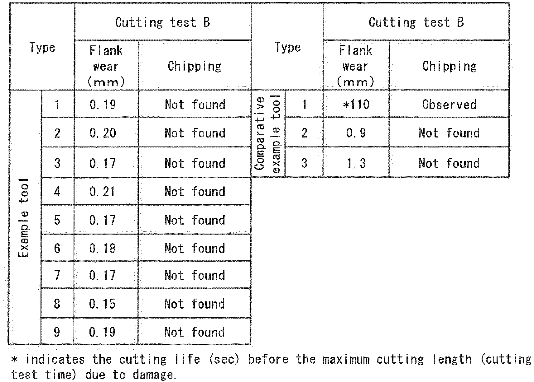
- Cast iron samples were subjected to high-rate cutting tests under the conditions:
- Work material: round bar in accordance with JIS·FCD600
- Cutting rate: 220m/min.
- Depth of cut: 0.25mm
- Feed: 0.21 mm/rev.
- Cutting time: 5 minutes
- (For reference, ordinary cutting rate is 145 m/min and ordinary feed is 0.2 mm/rev)
- The results of the cutting test B are shown in Table 9.
- Carbon steel samples were subjected to continuous high-rate cutting tests under the conditions:
- Work material: round bar in accordance with JlS·S55C (HB250)
- Cutting rate: 220 m/min.
- Depth of cut: 0.2 mm
- Feed: 0.24mm/rev.
- Cutting time: 5 minutes,
- (For reference, ordinary cutting rate is 145 m/min and ordinary feed is 0.25 mm/rev)
- The results of the cutting test C are shown in Table 10.
- Stainless steel samples were subjected to continuous wet high-rate cutting tests under the conditions (cutting condition B):
- Work material: round bar in accordance with JIS·SUS304 (HB180)
- Cutting rate: 140 m/min.
- Depth of cut: 2.0 mm
- Feed: 0.33 mm/rev.
- Cutting time: 9 minutes
- (For reference, ordinary cutting rate is 120 m/min and ordinary feed is 0.3 mm/rev)
- The results of the cutting test C are shown in Table 11.
- The results in Tables 8 to 11 demonstrate that Example tools 1 to 9 have high chipping and wear resistance without chipping and abnormal damage in Cutting tests A and B and Example tools 11 to 19 also have high chipping and wear resistance without chipping and abnormal damage in Cutting tests C and D. In contrast, Comparative Example tools 1 to 3 have chipping or noticeable flank wear in Cutting tests A and B, and Comparative Example tools 11 to 13 also have chipping or noticeable flank wear in Cutting tests C and D, resulting in short service lives.
- The embodiments are disclosed for illustrative purpose only, but not for limitation of the invention. The scope of the present invention should be determined by the description of Claims and includes a variety of equivalents and modifications of Claims.
-
- 1:
- tool substrate
- 2:
- interfacial region
- 3:
- hard coat film
- 4:
- hard coat layer




Claims (2)
- A surface-coated cutting tool comprising:a tool substrate; anda hard coat layer including a complex nitride layer on the tool substrate, the hard coat layer having an average thickness in the range of 0.5 to 10.0 µm, whereinthe complex nitride layer has a composition: (Ti1-x-yAlxMy)Nz where 0.35 ≤ x ≤ 0.80, 0.00 ≤ y < 0.20, 0.20 ≤ (1-x-y) ≤ 0.65, and 0.90 ≤ z ≤ 1.10 (where x, y, and z represents atomic ratios, M is at least one element selected from the group consisting of Groups 4 to 6 elements, Y, Si, La, and Ce in the IUPAC periodic table),the hard coat layer has an interfacial region extending from a point above the surface of the tool substrate toward the surface of the cutting tool and having a thickness in a range of 5 to 100 nm, and the N content ratio to the total of Ti, Al, M, and N contents is 10 to 30 atomic% at the point and increases toward the surface of the cutting tool.
- A surface-coated cutting tool comprising:a tool substrate; anda hard coat layer including a complex nitride layer on the tool substrate, the hard coat layer having an average thickness in the range of 0.5 to 10.0 µm, whereinthe complex nitride layer has a composition: (Cr1-x-yAlxMy)Nz where 0.35 ≤ x ≤ 0.80, 0.00 ≤ y ≤ 0.20, 0.20 ≤ (1-x-y) ≤ 0.65, and 0.90 ≤ z ≤ 1.10 (where x, y, and z represents atomic ratios, M is at least one element selected from the group consisting of Groups 4 to 6 elements, Y, Si, La, and Ce in the IUPAC periodic table),the hard coat layer has an interfacial region extending from a point above the surface of the tool substrate toward the surface of the cutting tool and having a thickness in a range of 5 to 100 nm, and the N content ratio to the total of Cr, Al, M, and N contents is 10 to 30 atomic% at the point and increases toward the surface of the cutting tool.
Applications Claiming Priority (3)
| Application Number | Priority Date | Filing Date | Title |
|---|---|---|---|
| JP2019022630 | 2019-02-12 | ||
| JP2019022629 | 2019-02-12 | ||
| PCT/JP2020/004465 WO2020166466A1 (en) | 2019-02-12 | 2020-02-06 | Hard coating cutting tool |
Publications (2)
| Publication Number | Publication Date |
|---|---|
| EP3925720A1 true EP3925720A1 (en) | 2021-12-22 |
| EP3925720A4 EP3925720A4 (en) | 2022-06-29 |
Family
ID=72044731
Family Applications (1)
| Application Number | Title | Priority Date | Filing Date |
|---|---|---|---|
| EP20756574.8A Pending EP3925720A4 (en) | 2019-02-12 | 2020-02-06 | Hard coating cutting tool |
Country Status (6)
| Country | Link |
|---|---|
| US (1) | US12303982B2 (en) |
| EP (1) | EP3925720A4 (en) |
| JP (1) | JP7733444B2 (en) |
| KR (1) | KR102870221B1 (en) |
| CN (1) | CN113453828A (en) |
| WO (1) | WO2020166466A1 (en) |
Cited By (2)
| Publication number | Priority date | Publication date | Assignee | Title |
|---|---|---|---|---|
| JP2024005014A (en) * | 2022-06-29 | 2024-01-17 | 住友電気工業株式会社 | Cutting tools |
| EP4527526A4 (en) * | 2022-09-22 | 2025-07-30 | Sumitomo Electric Industries | Cutting tool |
Families Citing this family (2)
| Publication number | Priority date | Publication date | Assignee | Title |
|---|---|---|---|---|
| KR20240011806A (en) * | 2021-06-30 | 2024-01-26 | 스미또모 덴꼬오 하드메탈 가부시끼가이샤 | cutting tools |
| JP7757889B2 (en) * | 2022-06-29 | 2025-10-22 | 住友電気工業株式会社 | cutting tools |
Family Cites Families (20)
| Publication number | Priority date | Publication date | Assignee | Title |
|---|---|---|---|---|
| JPS53138412A (en) | 1977-05-10 | 1978-12-02 | Kogyo Gijutsuin | Packing method of powder material to its most densely packed state |
| SE8300910L (en) | 1983-02-18 | 1984-08-19 | Santrade Ltd | COMPOSITION BODY CONSISTS OF A SUBSTRATE COATED WITH HEART, Wear-resistant finish |
| JP3027502B2 (en) | 1993-03-15 | 2000-04-04 | 健 増本 | Abrasion-resistant amorphous hard film and method for producing the same |
| JPH10237629A (en) | 1997-02-28 | 1998-09-08 | Nachi Fujikoshi Corp | Hard composite coating for cutting tools |
| AU2003244324A1 (en) * | 2002-06-25 | 2004-01-06 | Mitsubishi Materials Corporation | Coated cutting tool member |
| SE0701760L (en) | 2007-06-01 | 2008-12-02 | Sandvik Intellectual Property | Carbide inserts for parting, grooving and threading |
| JP2009119551A (en) | 2007-11-14 | 2009-06-04 | Mitsubishi Materials Corp | A surface-coated cutting tool that exhibits excellent chipping resistance with a hard coating layer in high-speed, high-feed cutting. |
| JP2011240435A (en) | 2010-05-19 | 2011-12-01 | Mitsubishi Materials Corp | Surface coated cutting tool excellent in heat resistance and fusion resistance |
| JP5617933B2 (en) | 2011-01-14 | 2014-11-05 | 日立ツール株式会社 | Hard film coated tool and manufacturing method thereof |
| JP5035479B2 (en) * | 2011-01-27 | 2012-09-26 | 三菱マテリアル株式会社 | Surface coated cutting tool with excellent chipping resistance and wear resistance |
| CN104789938A (en) * | 2014-01-22 | 2015-07-22 | 三菱综合材料株式会社 | Surface coating cutting tool hard coating layer of which gives play to excellent anti-tipping performance |
| US9962771B2 (en) * | 2014-06-06 | 2018-05-08 | Sumitomo Electric Hardmetal Corp. | Surface-coated tool and method of manufacturing the same |
| JP6709536B2 (en) * | 2015-05-26 | 2020-06-17 | 三菱マテリアル株式会社 | Surface coated cutting tool with excellent hard coating layer and chipping resistance |
| JP6677932B2 (en) * | 2015-08-29 | 2020-04-08 | 三菱マテリアル株式会社 | Surface coated cutting tool that demonstrates excellent chipping and wear resistance in heavy interrupted cutting |
| JP2017080878A (en) * | 2015-10-28 | 2017-05-18 | 三菱マテリアル株式会社 | Surface coated cutting tool |
| JP6931453B2 (en) * | 2015-10-30 | 2021-09-08 | 三菱マテリアル株式会社 | Surface coating cutting tool with excellent chipping resistance due to the hard coating layer |
| JP6614446B2 (en) * | 2016-03-17 | 2019-12-04 | 三菱マテリアル株式会社 | Surface coated cutting tool with excellent chipping and peeling resistance with excellent hard coating layer |
| JP6614447B2 (en) * | 2016-03-28 | 2019-12-04 | 三菱マテリアル株式会社 | Surface coated cutting tool with excellent chipping and peeling resistance with excellent hard coating layer |
| JP6674648B2 (en) * | 2016-03-31 | 2020-04-01 | 株式会社タンガロイ | Coated cutting tool |
| CN108472739B (en) | 2016-12-09 | 2020-11-27 | 住友电工硬质合金株式会社 | Surface-coated cutting tools |
-
2020
- 2020-02-06 CN CN202080013026.3A patent/CN113453828A/en active Pending
- 2020-02-06 EP EP20756574.8A patent/EP3925720A4/en active Pending
- 2020-02-06 WO PCT/JP2020/004465 patent/WO2020166466A1/en not_active Ceased
- 2020-02-06 US US17/427,128 patent/US12303982B2/en active Active
- 2020-02-06 JP JP2020545598A patent/JP7733444B2/en active Active
- 2020-02-06 KR KR1020217024372A patent/KR102870221B1/en active Active
Cited By (2)
| Publication number | Priority date | Publication date | Assignee | Title |
|---|---|---|---|---|
| JP2024005014A (en) * | 2022-06-29 | 2024-01-17 | 住友電気工業株式会社 | Cutting tools |
| EP4527526A4 (en) * | 2022-09-22 | 2025-07-30 | Sumitomo Electric Industries | Cutting tool |
Also Published As
| Publication number | Publication date |
|---|---|
| US20220143712A1 (en) | 2022-05-12 |
| CN113453828A (en) | 2021-09-28 |
| US12303982B2 (en) | 2025-05-20 |
| WO2020166466A1 (en) | 2020-08-20 |
| KR20210118093A (en) | 2021-09-29 |
| JP7733444B2 (en) | 2025-09-03 |
| JPWO2020166466A1 (en) | 2021-12-16 |
| EP3925720A4 (en) | 2022-06-29 |
| KR102870221B1 (en) | 2025-10-13 |
Similar Documents
| Publication | Publication Date | Title |
|---|---|---|
| EP3342512B1 (en) | Surface-coated cutting tool providing excellent chipping resistance and wear resistance in strong intermittent cutting work | |
| EP3225337B1 (en) | Surface-coated cutting tool with excellent chipping resistance and wear resistance | |
| EP2823923B1 (en) | Surface-coated cutting tool having therein hard coating layer capable of exhibiting excellent chipping resistance during high-speed intermittent cutting work | |
| EP3427872B1 (en) | Surface-coated cubic boron nitride sintered tool | |
| JP6620482B2 (en) | Surface coated cutting tool with excellent chipping resistance | |
| EP2177639B1 (en) | Titanium-base cermet, coated cermet, and cutting tool | |
| US12303982B2 (en) | Surface-coated cutting tool | |
| JP3402146B2 (en) | Surface-coated cemented carbide end mill with a hard coating layer with excellent adhesion | |
| EP3395484B1 (en) | Surface-coated cubic boron nitride sintered compact tool | |
| JP2013116509A (en) | Surface coated cutting tool | |
| JP2021126738A (en) | Surface coating cutting tool that demonstrates excellent chipping resistance and wear resistance in strong intermittent cutting | |
| EP3839086A1 (en) | Cemented carbide and coated cemented carbide, and tool including same | |
| JP2020132972A (en) | Cemented Carbide and Cutting Tools | |
| JP2020132971A (en) | Cemented carbide and cutting tool | |
| WO2016148056A1 (en) | Surface-coated cutting tool with rigid coating layers exhibiting excellent chipping resistance | |
| EP3219420B1 (en) | Surface-coated cutting tool | |
| WO2016052479A1 (en) | Surface-coated cutting tool having excellent chip resistance | |
| EP4295978A1 (en) | Surface-coated cutting tool | |
| EP3778080A1 (en) | Surface-coated cutting tool | |
| EP3858524A1 (en) | Surface coated cutting tool having hard coating layer exhibiting excellent chipping resistance | |
| EP4129541B1 (en) | Surface-coated cutting tool | |
| EP4309835A1 (en) | Surface-coated cutting tool | |
| JP2020142312A (en) | Surface coating cutting tool | |
| JP2023134119A (en) | surface coated cutting tools | |
| JP5945162B2 (en) | Surface coated cutting tool |
Legal Events
| Date | Code | Title | Description |
|---|---|---|---|
| STAA | Information on the status of an ep patent application or granted ep patent |
Free format text: STATUS: THE INTERNATIONAL PUBLICATION HAS BEEN MADE |
|
| PUAI | Public reference made under article 153(3) epc to a published international application that has entered the european phase |
Free format text: ORIGINAL CODE: 0009012 |
|
| STAA | Information on the status of an ep patent application or granted ep patent |
Free format text: STATUS: REQUEST FOR EXAMINATION WAS MADE |
|
| 17P | Request for examination filed |
Effective date: 20210804 |
|
| AK | Designated contracting states |
Kind code of ref document: A1 Designated state(s): AL AT BE BG CH CY CZ DE DK EE ES FI FR GB GR HR HU IE IS IT LI LT LU LV MC MK MT NL NO PL PT RO RS SE SI SK SM TR |
|
| DAV | Request for validation of the european patent (deleted) | ||
| DAX | Request for extension of the european patent (deleted) | ||
| RIN1 | Information on inventor provided before grant (corrected) |
Inventor name: ASANUMA, HIDETOSHI |
|
| A4 | Supplementary search report drawn up and despatched |
Effective date: 20220531 |
|
| RIC1 | Information provided on ipc code assigned before grant |
Ipc: C23C 14/32 20060101ALI20220524BHEP Ipc: C23C 28/00 20060101ALI20220524BHEP Ipc: C23C 30/00 20060101ALI20220524BHEP Ipc: C23C 14/06 20060101ALI20220524BHEP Ipc: B23B 51/00 20060101ALI20220524BHEP Ipc: B23C 5/16 20060101ALI20220524BHEP Ipc: B23B 27/14 20060101AFI20220524BHEP |