EP3925430A2 - Corn head adjustment system with integrated actuation - Google Patents
Corn head adjustment system with integrated actuation Download PDFInfo
- Publication number
- EP3925430A2 EP3925430A2 EP21173874.5A EP21173874A EP3925430A2 EP 3925430 A2 EP3925430 A2 EP 3925430A2 EP 21173874 A EP21173874 A EP 21173874A EP 3925430 A2 EP3925430 A2 EP 3925430A2
- Authority
- EP
- European Patent Office
- Prior art keywords
- deck plate
- center
- segment
- fold
- actuator
- Prior art date
- Legal status (The legal status is an assumption and is not a legal conclusion. Google has not performed a legal analysis and makes no representation as to the accuracy of the status listed.)
- Granted
Links
Images







Classifications
-
- A—HUMAN NECESSITIES
- A01—AGRICULTURE; FORESTRY; ANIMAL HUSBANDRY; HUNTING; TRAPPING; FISHING
- A01D—HARVESTING; MOWING
- A01D41/00—Combines, i.e. harvesters or mowers combined with threshing devices
- A01D41/12—Details of combines
- A01D41/14—Mowing tables
- A01D41/144—Foldable headers
-
- A—HUMAN NECESSITIES
- A01—AGRICULTURE; FORESTRY; ANIMAL HUSBANDRY; HUNTING; TRAPPING; FISHING
- A01B—SOIL WORKING IN AGRICULTURE OR FORESTRY; PARTS, DETAILS, OR ACCESSORIES OF AGRICULTURAL MACHINES OR IMPLEMENTS, IN GENERAL
- A01B73/00—Means or arrangements to facilitate transportation of agricultural machines or implements, e.g. folding frames to reduce overall width
- A01B73/02—Folding frames
- A01B73/04—Folding frames foldable about a horizontal axis
-
- A—HUMAN NECESSITIES
- A01—AGRICULTURE; FORESTRY; ANIMAL HUSBANDRY; HUNTING; TRAPPING; FISHING
- A01B—SOIL WORKING IN AGRICULTURE OR FORESTRY; PARTS, DETAILS, OR ACCESSORIES OF AGRICULTURAL MACHINES OR IMPLEMENTS, IN GENERAL
- A01B73/00—Means or arrangements to facilitate transportation of agricultural machines or implements, e.g. folding frames to reduce overall width
- A01B73/02—Folding frames
- A01B73/04—Folding frames foldable about a horizontal axis
- A01B73/044—Folding frames foldable about a horizontal axis the axis being oriented in a longitudinal direction
-
- A—HUMAN NECESSITIES
- A01—AGRICULTURE; FORESTRY; ANIMAL HUSBANDRY; HUNTING; TRAPPING; FISHING
- A01D—HARVESTING; MOWING
- A01D45/00—Harvesting of standing crops
- A01D45/02—Harvesting of standing crops of maize, i.e. kernel harvesting
-
- A—HUMAN NECESSITIES
- A01—AGRICULTURE; FORESTRY; ANIMAL HUSBANDRY; HUNTING; TRAPPING; FISHING
- A01D—HARVESTING; MOWING
- A01D45/00—Harvesting of standing crops
- A01D45/02—Harvesting of standing crops of maize, i.e. kernel harvesting
- A01D45/021—Cornheaders
Definitions
- This disclosure relates to a corn head adjustment system for an agricultural operation.
- Effective and efficient agricultural operation may involve large implements to process multiple rows at a time.
- a corn head that operates to harvest eight, twelve, or even more rows during a single pass.
- Some corn heads may be folded to facilitate transport and storage.
- accommodating and implementing the fold and unfold processes may be challenging.
- the disclosure provides a corn head adjustment system.
- a corn head configured to be mounted on an agricultural machine.
- the corn head includes a first wing segment including a first wing segment frame; a first deck plate rod mounted to the first wing segment frame; and a first series of deck plates, at least a portion of which are repositionable upon lateral movement of first deck plate rod.
- the corn head further includes a center segment arranged proximate to the first wing segment, the center segment including a center frame; a center deck plate rod mounted to the center frame; and a second series of deck plates, at least a portion of which are repositionable upon lateral movement of center deck plate rod.
- the corn head also includes a corn head adjustment system with a first fold actuator extending between the first wing segment frame and the center frame; a first deck plate actuator mounted on at least one of the first wing segment frame or the center frame and configured to reposition at least one of the first deck plate rod or the center deck plate rod; and corn head hydraulics fluidly coupled to receive a fluid from a source and to direct the fluid to selectively actuate the first fold actuator in order to fold the first wing segment relative to the center segment, to selectively actuate the first fold actuator in order to unfold the first wing segment relative to the center segment, to selectively actuate the first deck plate actuator in order to decouple the first deck plate rod from the center deck plate rod, and to selectively actuate the first deck plate actuator in order to couple the first deck plate rod to the center deck plate rod.
- a corn head adjustment system with a first fold actuator extending between the first wing segment frame and the center frame; a first deck plate actuator mounted on at least one of the first wing segment frame or the center frame
- the corn head hydraulics is configured to actuate the first fold actuator in order to fold the first wing segment relative to the center segment and to actuate the first deck plate actuator in order to decouple the first deck plate rod from the center deck plate rod.
- the corn head hydraulics is configured to actuate the first fold actuator in order to unfold the first wing segment relative to the center segment.
- a corn head adjustment system for a corn head with a first wing segment and a center segment arranged proximate to the first wing segment; the first wing segment including a first wing segment frame, a first deck plate rod mounted to the first wing segment frame, and a first series of deck plates, at least a portion of which are repositionable upon lateral movement of first deck plate rod; and the center segment including a center frame, a center deck plate rod mounted to the center frame, and a second series of deck plates, at least a portion of which are repositionable upon lateral movement of center deck plate rod.
- the corn head adjustment system includes a first fold actuator extending between the first wing segment frame and the center frame; a first deck plate actuator mounted on at least one of the first wing segment frame or the center frame and configured to reposition at least one of the first deck plate rod or the center deck plate rod; and corn head hydraulics fluidly coupled to receive a fluid from a source and to direct the fluid to selectively actuate the first fold actuator in order to fold the first wing segment relative to the center segment, to selectively actuate the first fold actuator in order to unfold the first wing segment relative to the center segment, to selectively actuate the first deck plate actuator in order to decouple the first deck plate rod from the center deck plate rod, and to selectively actuate the first deck plate actuator in order to couple the first deck plate rod to the center deck plate rod.
- the corn head hydraulics is configured to actuate the first fold actuator in order to fold the first wing segment relative to the center segment and to actuate the first deck plate actuator in order to decouple the first deck plate rod from the center deck plate rod.
- the corn head hydraulics is configured to actuate the first fold actuator in order to unfold the first wing segment relative to the center segment.
- Agricultural implements of an agricultural machine may be wide in order to processes a number of rows simultaneously to improve operational efficiency. Since the corn head is so wide, it is separated onto one or more portions that enable folding in order to more easily transport and store the agricultural machine.
- the corn head may have wing segments mounted on each end of a center segment that fold onto the center segment. The folding and unfolding of the wing segments are implemented hydraulically and may function to accommodate the various operational relationships between the segments.
- the corn head adjustment system may include various types of actuators (e.g., lock actuators, deck plate actuators, and fold actuators) that are hydraulically integrated in order to collectively reposition the actuators with a single command and/or a single fluid pressure source as a sequence during fold and unfold processes.
- actuators may be dual-acting actuators.
- the deck plate actuators may be positioned on each wing segment and cooperate to reposition the deck plates across the corn head.
- the corn head adjustment system may implement a resume function at the end of an unfold process in order to return the deck plates to a previous spacing.
- the hydraulics of the corn head adjustment system may have various types of control mechanisms, including hydraulically activated valves, electrically activated solenoid valves, and combinations thereof.
- the corn head adjustment system may include a force reduction or relief arrangement that is activated at the end of a fold process and/or unfold process to reduce the amount of force (or load) that the actuators place on the frames when assisted by gravity.
- force relief arrangements may be activated with a mechanical sensor that determines the relative positions of the frame segments; a sensor integrated into the respective actuators; and/or sensor or pressure elements within the hydraulics. It should be noted that the various examples discussed herein may be implemented as necessary or desired with one another as appropriate.
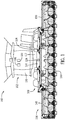
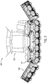
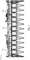
- FIGS. 1-3 depict an agricultural machine 100 with a vehicle 102 that supports a work implement, which in this example in a corn head 104 that functions to process corn.
- a corn head 104 is depicted, the examples discussed herein may be applicable to other type of implements.
- the corn head 104 is formed by a first (or left) wing segment 130, a second (or right) wing segment 140, and a center segment 150.
- One of wing segments 130, 140 is arranged on each end of the center segment 150, which may be mounted to the vehicle 102 to secure the overall corn head 104.
- the corn head 104 may be modified or adjusted in various ways by a head adjustment system 106, including into an unfolded state as shown in FIG. 1 , in between unfolded and folded states as shown in FIG. 2 , and into the folded state as shown in FIG. 3 . a folded state.
- the machine 100 operates in the unfolded position during an agricultural operation (e.g., when collecting and processing corn) and in the folded position during transport or storage of the machine 100.
- the left wing segment 130 may be a mirror image of the right wing segment 140 with similar components, as may be the case with the left and right sides of the center segment 150. Additional details regarding the corn head 104 and head adjustment system 106 are provided below.
- the work vehicle 102 includes a vehicle frame 108 supporting the cab 110 and a powertrain 112 supported on the vehicle frame 108 that generates power for propulsion and/or other tasks to be performed by the work vehicle 102.
- the powertrain 112 may include an engine, transmission, steering system, wheels, and the like for propelling and maneuvering the work vehicle 102, either autonomously or based on commands by the operator.
- work vehicle 102 may include a hydraulic system (generally "vehicle hydraulics") 114 in which power generated by the powertrain 112 is distributed via fluid pressure to perform various functions on the work vehicle 102 and/or the corn head 104. Additional details regarding the vehicle hydraulics 114 are provided below.
- the work vehicle 102 may include various other components or systems that are typical on work vehicles. Examples include actuation systems, lubrication and cooling systems, battery systems, exhaust treatment systems, braking systems, and the like.
- the agricultural machine 100 may further include a controller 120 to perform and implement one or more functions associated with operating the work vehicle 102 and/or corn head 104.
- the vehicle controller 120 may also facilitate automatic or manual maneuvering of the vehicle traversing the field and actuation of the processing elements of the vehicle 102 and/or corn head 104.
- the controller 120 may operate to control the elements that process the corn on the corn head 104 and/or within the work vehicle 102. Additionally, the controller 120 may facilitate operation of the corn head adjustment system 106, as described below.
- the vehicle controller 120 may be configured as a computing device with associated processor devices and memory architectures, as a hardwired computing circuit (or circuits), as a programmable circuit, as a hydraulic, electrical or electro-hydraulic controller, or otherwise. As such, the vehicle controller 120 may be configured to execute various computational and control functionality with respect to the work vehicle 102, the corn head 104, and/or the head adjustment system 106.
- the vehicle controller 120 may be configured to receive input signals in various formats from a number of sources (e.g., including from the operator via operator interfaces 122, one or more sensors 124, units, and systems onboard or remote from the machine 100); and in response, the vehicle controller 120 generates one or more types of commands for implementation by the various systems on or outside the agricultural machine 100.
- sources e.g., including from the operator via operator interfaces 122, one or more sensors 124, units, and systems onboard or remote from the machine 100.
- the vehicle controller 120 may be configured to receive input commands and to interface with an operator via human-vehicle interfaces in the forms of one or more operator interfaces 122, which may be disposed inside the cab 110 of the work vehicle 102 for easy access by the vehicle operator.
- the operator interfaces 122 may be configured in a variety of ways, including one or more joysticks, various switches or levers, one or more buttons, a touchscreen interface, a keyboard, a speaker, a microphone associated with a speech recognition system, or various other human-machine interface devices.
- the operator may use the operator interfaces 122 to command or otherwise implement the adjustment of various aspects of the corn head 104 in association with the corn head adjustment system 106, including wing folding and unfolding, as well as wing locking and deck plate adjustments.
- the work machine 100 may include one or more sensors 124 on the work vehicle 102 and/or corn head 104 that function to collect information associated with the agricultural machine 100 and the associated environment. Such information may be provided to the vehicle controller 120 for use by the corn head adjustment system 106.
- the sensor 124 includes one or more actuator sensors, wing position sensors, and/or deck plate sensors. Other sensors and associated components may be provided.
- FIG. 4 is a schematic representation of the head adjustment system 106 on the vehicle 102 and/or corn head 104.
- the corn head adjustment system 106 may be considered to include the controller 120, at least segments of the vehicle hydraulics 114, and various components of the corn head 104, particularly actuators and hydraulics of the corn head 104.
- the corn head 104 is formed by left and right wing segments 130, 140 on either side of center segment 150.
- the wing and center segments 130, 140, 150 are formed by respective frames 132, 142, 152 on which various elements may be supported.
- each deck plate set 170a-170l defines a spacing that admits the corn stalks for further processing and removal of the corn ears.
- each deck plate set 170a-170l includes a stationary plate and an adjustable plate mounted on a rod 134, 144, 154, laterally repositionable to modify the spacings.
- the deck plate rods 134, 144, 154 include a left deck plate rod 134 positioned on the left wing frame 132, a right deck plate rod 144 positioned on the right wing frame 142, and a center deck plate rod 154 positioned on the center frame 152.
- the left and right wing deck plate rods 134, 144 abut the ends of the center deck plate rod 154.
- the center deck plate rod 154 is configured to be laterally repositionable by the mechanical force of repositioning the left and right wing deck plate rods 134, 144.
- the corn head 104 includes lock assemblies 136, 146 mounted on the ends of the center frame 152.
- the lock assemblies 136, 146 may also have a portion mounted on the wing frames 132, 142 that enable the wing frames 132, 142 to be locked relative to the center frame 152, as discussed in greater detail below.
- the head adjustment system 106 operates to modify the position of one or more components of the corn head 104 on the vehicle 102.
- the controller 120 operates to command actuators 180, 190, 200, 210, 220, 230 of the head adjustment system 106 to reposition aspects of the corn head 104.
- the head adjustment system 106 actuates the deck plate actuators 180, 190, the lock actuators 200, 210, and the fold actuators 220, 230 in order to respectively modify the deck plates 170, the lock assemblies 136, 146, and the wing segments 130, 140, which may be implemented individually and/or in combination with one another.
- Such commands may be implemented by vehicle hydraulics 114 and head hydraulics 240.
- the hydraulics 114, 240 refer to the combination of conduits, passages, valves, tanks, pumps, electrical and fluid connections, and the like that operate to implement the functions described herein. More specific example arrangements of the hydraulics 114, 240 are provided below.
- the head adjustment system 106 includes a first (or left) fold actuator 220 mounted on the left wing frame 132 and further coupled to the center frame 152 and a second (or right) wing fold actuator 230 mounted on the right wing frame 142 and further coupled to the center frame 152.
- the fold actuators 220, 230 have first (or extended) positions to unfold the wing segments 130, 140 relative to the center segment 150, and the fold actuators 220, 230 have second (or retracted) positions to lock the wing segments 130, 140 relative to the center segment 150.
- each deck plate set 170a-1701 includes a stationary deck plate and an adjustable deck plate that may be repositioned by the head adjustment system 106 to modify the spacings into the associated corn processing elements, as described below.
- the head adjustment system 106 may be considered to include wing deck plate rod 134, 144 supported in each wing frame 132 and center deck plate rod 154 supported in the center frame 152. During operation and when the wing segments 130, 140 are in the unfolded position, the wing deck plate rods 134, 144 abut the center deck plate rod 154.
- Each adjustable deck plate of the deck plate sets 170a-170l may be fixed to one of the wing deck plate rods 134, 144 or the center deck plate rod 154.
- the adjustable deck plates of deck plate sets 170a-170c are coupled to the left wing deck plate rod 134; the adjustable deck plates of deck plate sets 170d-170i are coupled to the center deck plate rod 154; and the adjustable deck plates of deck plate sets 170j-170l are coupled to the right wing deck plate rod 144.
- the head adjustment system 106 further includes deck plate actuators 180, 190.
- a first (or left) deck plate actuator 180 is coupled to the left wing frame 132 and is further coupled to the left wing deck plate rod 134
- a second (or right) deck plate actuator 190 is coupled to the right wing frame 142 and is further coupled to the right wing deck plate rod 144.
- the deck plate actuators 180, 190 may laterally adjust the deck plate rods 134, 144.
- the deck plate actuators 180, 190 may move both the rods 134, 144 away from the center deck plate rod 154 (e.g., in opposite, outward directions) or towards the center deck plate rod 154 (e.g., in the opposite, inward directions); or the deck plate actuators 180, 190 may cooperate to move both the rods 134, 144 in the same direction to push the center deck plate rod 154 in the actuated direction in order to collectively increase or decrease the spacings of the deck plate sets 170a-170l.
- moving the rods 134, 144, 154 toward the left side wing segment 130 e.g., to the right in FIG.
- the head adjustment system 106 may further include a first (or left) lock assembly 136 that functions to secure and align the left wing segment 130 to the center segment 150 and a second (or right) lock assembly 146 that functions to secure and align the right wing segment 140 to the center segment 150. Additional details regarding the lock assemblies 136, 146 are provided below.
- the lock actuators 200, 210 have first (or extended) positions to lock the lock assemblies 136, 146 (e.g., to secure the respective wing segment 130, 140 to the center segment 150), and the lock actuators 200, 210 have second (or retracted) positions to unlock the lock assemblies 136, 146 (e.g., to release the respective wing segment 130, 140 relative to the center segment 150). Additional information regarding the hydraulics 114, 240 that actuate actuators 180, 190, 200, 210, 220, 230 of the corn head adjustment system 106 is provided below after a discussion of the mechanical structure and elements of the corn head 104 depicted in FIG. 5-19 .
- FIGS. 5-8 depict various views of the corn head 104, including the left wing segment 130, the right wing segment 140, and the center segment 150.
- the corn head includes an array of processing elements 164 and deck plates 170 separated and partially housed by covers 160 such that corn may be separated from the stalk and transported to the vehicle 102 by an auger 162.
- the corn head 104 may be able to process twelve (12) rows of corn, although other examples may be able to accommodate other numbers of rows.
- the processing elements 164 that are used to gather, pinch, chop, and discard the corn stalk and to direct the corn ears to the feederhouse of the vehicle 102 ( FIG. 1 ) may include intermeshing stalk rolls, chopping or knife elements, gathering chains, augers, guards, wear plates, and/or various drive components.
- FIGS. 9-19 depict additional views of the corn head 104, particularly elements of the corn head adjustment system 106.
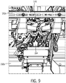
- FIG. 9 is a bottom rear view of a portion of the corn head 104
- FIG. 10 is a rear view of a portion of the corn head 104
- FIG. 11 is a top front view of a portion of the corn head 104 along line 11-11 of FIG. 6
- FIG. 12 is a bottom rear view of a portion of the corn head 104
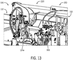
- FIG. 13 is a top rear view of a portion of the corn head 104
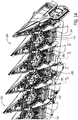
- FIG. 14 is a front underside view of a portion of the corn head 104
- FIG. 15 is a front underside view of a portion of the corn head 104 representing section 15-15 of FIG. 14 ;
- FIG. 9 is a bottom rear view of a portion of the corn head 104
- FIG. 10 is a rear view of a portion of the corn head 104
- FIG. 11 is a top front view of a portion of the corn head 104
- FIG. 16 is a cross-sectional view of the corn head 104 through line 16-16 of FIG. 15 ;
- FIG. 17 is a cross-sectional view of the corn head 104 through line 17-17 of FIG. 16 ;
- FIG. 18 is a partial underside view of the corn head 104 along line 18-18 of FIG. 8 ; and
- FIG. 19 is a partial underside view of the corn head 104 along line 19-19 of FIG. 14 .
- FIG. 9 better depicts the processing elements 164 mounted on in between the left wing segment frame elements 132a, 132b.
- the view of FIG. 9 additional provides an example of a set of deck plates 170 that set the spacing for processing the corn.
- the lift actuator 230 includes a cylinder mounted by a bracket 152c on a center frame segment element 152a and a rod mounted by a bracket 142c on a right frame segment element 142a. As a result of this arrangement, retraction of the lift actuator 230 operates to fold the wing frame 142 relative to the center frame 152.
- the left wing segment 130 and lift actuator 220 are similarly arrangement.
- the view of FIG. 10 further depicts drive elements 166a, 166b for driving the processing elements 164.
- FIGS. 11 and 12 are similar to that of FIG. 10 , and particularly depict a fold stop 152d ( FIG. 11 ) that supports the right wing segment 140 on the center segment 150 and unfold stops 142d, 152e that abut one another when unfolded.
- the force on stops 142d, 152d, 152e may be mitigated or addressed by the force relief arrangements of the corn head hydraulics discussed below.
- the lift actuator 220 extends between the left wing frame 132 and the center frame 152 to fold and unfold the left wing segment 130 relative to the center segment 150.
- the view additionally depicts a sensor 124a mounted on the center frame 152 that operates to determine the angle of the wing frame 132 relative to the center frame 152 in order to actuate the force relief arrangements of the of the corn head hydraulics discussed below.
- the view of FIG. 13 also depicts a valve block 300 that forms part of the corn head hydraulics discussed in greater detail below.
- the view of FIG. 14 is a front underside view of a portion of the corn head 104 and depicts various elements discussed in greater detail below.
- the view of FIG. 14 depicts the deck plate actuator 180 that operates to reposition the deck plate rod 134, and by abutment, the deck plate rod 154 of the center segment 150.
- the deck plate actuator 180 is mounted on the left segment frame 132 to cooperate with a deck plate actuator 190 mounted on the right wing frame 142 (not shown in FIG. 14 ) to reposition the deck plates 170.
- the lock assembly 136 is mounted on the center frame 152 and cooperates with the lock actuator 200 in order to lock the left wing segment 130 relative to the center segment 150.
- lock actuator 200 is extended to lock the lock assembly 136 and retracted to unlock the lock assembly 136.
- a similar lock assembly 136 and lock actuator 210 are provided on the other side of the center frame 152 to lock the right wing segment 140 to the center segment 150.
- FIGS. 15-18 provide additional views of the lock assembly 136 and lock actuator 200.
- the cylinder 202 of the lock actuator 200 is mounted on the center frame 152 and the rod 204 of the lock actuator 200 is positioned to extend into the lock assembly 136.
- an outer portion 136a of the lock assembly 136 is mounted on the center frame 152 and an inner portion 136b of the lock assembly 136 is mounted on the left wing frame 132.
- the inner portion 136b is partially housed within the outer portion 136a and each has generally aligned slots.
- the portions 136a, 136b When the lock actuator 200 is retracted, the portions 136a, 136b may move relative to one another; but when the lock actuator 200 is extended through the slots into the portions 136a, 136b, the portions 136a, 136b are locked relative to one another.
- an arm bracket 136c is mounted to the rod 204 of the lock actuator 200, to the center frame 152, and to a cover 160.
- the cover 160 is maintained in a default position over the processing elements 164.
- the cover 160 is pivoted slightly (as best shown in FIG. 2 ) by the arrangement of the arm bracket 136c to enable the cover to accommodate the folding process.
- FIG. 18 depicts an underside of the corn head 104 and particularly depicts portions of the deck plates 170, the center deck plate rod 154, the right wing deck plate rod 144, and the right wing fold actuator 230.
- the deck plate rods 144, 154 operate to reposition the spacing of the deck plates 170 and to retract the right wing deck plate rod 144 relative to the center deck plate rod 154 to enable folding of the right wing segment 140 relative to the center segment 150.
- the view of FIG. 19 depicts an underside of the corn head 104 and particularly depicts a closer view of deck plate actuator 180 that repositions the left deck plate rod 134 for retraction and for repositioning of the deck plates 170.
- FIG. 20 is a schematic view of the corn head adjustment system 106 of the agricultural machine 100 of FIG. 1 according to a first embodiment.
- the corn head adjustment system 106 includes vehicle hydraulics 114 and head hydraulics 240 that operate the actuators 180, 190, 200, 210, 220, 230.
- a portion of the head hydraulics 240 is embodied within a corn head valve block 300 that may be mounted on the center segment 150 of the corn head 104 that fluidly communicates with the vehicle hydraulics 114 and the actuators 180, 190, 200, 210, 220, 230.
- the valve block 300 may be considered a unit or module that houses various hydraulic components for selective distribution.
- the vehicle hydraulics 114 may include a pump 304, a drain or source 306, and a vehicle directional valve 308.
- the pump 304 pressurizes the fluid from the drain 306, and the vehicle directional valve 308 facilitates the distribution in and out of the vehicle hydraulics 114 via a supply line 310 and a drain line 311.
- the vehicle directional valve 308 may be solenoid valve commanded by signals from the controller 120 into a first position 308a, a second position 308b, and a third (or default) position 308c.
- the combine head coupling element 312 couples the vehicle hydraulics 114 to the head hydraulics 240.
- first and second lines 314, 316 extend from ports 318a, 318b between the vehicle hydraulics 114 and the head hydraulics 240, particularly to the valve block 300.
- valve block 300 includes a body 320 (schematically shown) with the two primary ports 322a, 322b and a number of actuator ports 324a-324l such that the components of the valve block 300 may distribute fluid flow between the vehicle hydraulics 114 and the actuator 180, 190, 200, 210, 220, 230.
- the wing fold actuator set includes the left wing fold actuator 220 and right wing fold actuator 230.
- the left wing fold actuator 220 includes a cylinder 222 and a rod 224 partially arranged within the cylinder 222 with a piston head defining chambers such that fluid flowing into a retraction-side chamber of the cylinder 222 via line 354 operates to retract the rod 224 and fluid flowing into an extension-side chamber of the cylinder 222 via line 355 operates to extend the rod 224.
- right wing fold actuator 230 includes a cylinder 232 and a rod 234 partially arranged within the cylinder 232 with a piston head defining chambers such that fluid flowing into a retraction-side chamber of the cylinder 232 via line 356 operates to retract the rod 234 and fluid flowing into an extension-side chamber of the cylinder 232 via line 357 operates to extend the rod 234.
- the fold actuators 220, 230 are dual-acting actuators that may be actively commanded in each direction. As shown, lines 354-357 are respectively coupled to ports 324a-324d.
- retraction of the rods 224, 234 of the wing fold actuators 220, 230 operates to fold up the wing segments 130, 140 relative to the center segment 150; and extension of the rods 224, 234 of the wing fold actuators 220, 230 operates to unfold the wing segments 130, 140 relative to the center segment 150.
- each wing fold actuator 220, 230 may be associated with a "velocity fuse" valve 226, 236.
- the velocity fuse valves 226, 236 generally enable flow of fluid through the associated lines 354, 356; however, upon identifying a predetermined rate of fluid flow out of the respective actuator 220, 230, the respective velocity fuse valve 226, 236 activates to block the flow of fluid through the line 354, 356.
- velocity fuse valves 226, 236 operate as safety features to prevent the wing segments 130, 140 from falling if a line is severed and fluidly flows too quickly out of the actuators 220, 230.
- the velocity fuse valves 226, 236 may have any suitable activation setting, such as 8 gallons per minute.
- the wing lock actuator set includes the left wing lock actuator 200 and the right wing lock actuator 210.
- the left wing lock actuator 200 includes a cylinder 202 and a rod 204 partially arranged within the cylinder 202 with a piston head defining chambers such that fluid flowing into a retraction-side chamber via line 358 operates to retract the rod 204 and fluid flowing into an extension-side chamber of the cylinder 202 via line 359 operates to extend the rod 204.
- the right wing lock actuator 210 includes a cylinder 212 and a rod 214 partially arranged within the cylinder 212 with a piston head defining chambers such that fluid flowing into a retraction-side chamber via line 360 operates to retract the rod 214 and fluid flowing into an extension-side chamber of the cylinder 212 via line 361 operates to extend the rod 214.
- the deck plate actuators 180, 190 are dual-acting actuators that may be actively commanded in each direction. As shown, lines 358-361 are respectively coupled to ports 324e-324h.
- retraction of the rods 204, 214 of the wing lock actuators 200, 210 operates to unlock the wing segments 130, 140 relative to the center segment 150; and extension of the rods 204, 214 of the wing lock actuators 200, 210 operates to lock the wing segment 130, 140 relative to the center segment 150.
- the wing deck plate actuator set includes the left wing deck plate actuator 180 and the right deck plate actuator 190.
- the left wing deck plate actuator 180 includes a cylinder 182 and a rod 184 partially arranged within the cylinder 182 with a piston head defining chambers such that fluid flow into a retraction-side chamber via line 362 operates to retract the rod 184 and fluid flowing into an extension-side chamber of the cylinder 182 via line 363 operates to extend the rod 184.
- the right deck plate actuator 190 includes a cylinder 192 and a rod 194 partially arranged within the cylinder 192 with a piston head defining chambers such that fluid flow into a retraction-side chamber via line 364 operates to retract the rod 194 and fluid flowing into an extension-side chamber of the cylinder 192 via line 365 operates to extend the rod 194.
- the lock actuators 200, 210 are dual-acting actuators that may be actively commanded in each direction. As shown, lines 362-365 are respectively coupled to ports 324i-324l.
- retraction of the rods 184, 194 of the wing deck plate actuators 180, 190 operates to decouple the wing deck plate rods 134, 144 the wing segments 130, 140 relative to the center segment 150; and extension of the rods 184, 194 of the wing deck plate actuators 180, 190 operates to couple the wing segments 130, 140 relative to the center segment 150.
- the deck plate actuators 180, 190 may also be used to modify the spacing of the deck plate rods 134, 144, 154 (and thus, the spacings of the deck plates 170), as well as to resume or return to a predetermined spacing after unfolding the wing segments 130, 140.
- first primary lines 400, 401 and second primary lines 402, 403 extend between primary ports 322a, 322b to a head directional valve 410.
- the head directional valve 410 may be considered to have a first (or fold) position 410a, a second (or unfold) position 410b, and a third (or default) position 410c.
- the head directional valve 410 may be solenoid valve commanded by signals from the controller 120 into one or more of the positions 410a, 410b, 410c.
- the lines 400, 401, 402, 403 may be considered supply lines or drain lines.
- a shuttle valve 420 is fluidly coupled to the head directional valve 410 via lines 422, 424, respectively attached to opposite ends of the shuttle valve 420.
- a first counterbalance valve 430 is fluidly coupled to the head directional valve 410 via line 422, and a second counterbalance valve 432 is fluidly coupled to the head directional valve 410 via line 422.
- the first counterbalance valve 430 may be actuated by a pilot line 434 extending to line 424
- the second counterbalance valve 432 may be actuated by a pilot line 436 extending to line 422, as discussed in greater detail below, in order to selectively restrict the flow of fluid from the fold actuators 220, 230.
- a distribution element 440 is fluidly coupled to the first counterbalance valve 430 via line 442 and operates to split the flow from (and combine the flow to, as appropriate) the first counterbalance valve 430, and thus, line 422. As shown, the distribution element 440 divides the flow from line 422 between line 444, which is fluidly coupled to port 324a, and line 446, which is fluidly coupled to port 324c. As such, and as discussed in greater detail below, lines 444, 446 supply fluid flow to, or receive flow from, the retraction-side of fold actuator 220, 230.
- a line 450 extends from the second counterbalance valve 432 and extends to port 324b, which in turn is fluidly coupled to the extension-side of the left wing fold actuator 220.
- a line 452 branches from line 450 and is selectively fluidly coupled to port 324d via an isolation valve 456.
- the isolation valve 456 may include a first position 456a in which line 452 is fluidly coupled to port 324d and a second position 456b in which line 452 is not fluidly coupled to port 324d.
- valve 456 is solenoid valve with spring return.
- a line 460 extends from the center port of the shuttle valve 420 and is fluidly coupled to port 324i and, via line 462, to port 324k. As such, flow from the shuttle valve 420 may be directed through lines 460, 462, 362, 364 and ports 324i, 324k to the retraction-sides of the deck plate actuators 180, 190.
- pressure from line 460 may also be used to retract the lock actuators 200, 210 via lines 464, 466, 354, 356 and ports 324e, 324g.
- Line 464 extends from line 460 to port 324g, and line 466 extends from line 464 to port 324e.
- a check valve 470 may be positioned on line 464 to selectively check or prevent flow from the retraction-side of the lock actuators 200, 210 to line 460 based on the pressure in pilot line 472, discussed in greater detail below.
- fluid pressure into port 322a may be used to retract all six actuators 180, 190, 200, 210, 220, 230 when the head directional valve 410 is in the first position 410a; and fluid pressure into port 322a may be used to extend the fold actuators 220, 230 and retract the lock and deck plate actuator 180, 190, 200, 210 when the head directional valve 410 is in the second position 410b.
- the valve block 300 may also include a number of flow paths that interact directly with the primary lines 400, 401, 402, 403 that are introduced briefly here and the functions to which will be discussed in greater detail below.
- a line 480 extends from the first primary line 400 to the second primary line 402 with a check valve 482 on line 480 to prevent the flow of fluid from port 322a through line 400 to line 402.
- line 484 extends from primary line 400 to port 324j, thereby enabling selective extension of the left deck plate actuator 180, as discussed in greater detail below.
- a blocker valve 490 is positioned on line 484 to selectively block flow through line 484 in a first position 480a and allow flow through line 484 in a second position 480b.
- the blocker valve 490 may be solenoid activated based on signals from the controller 120 and spring returned.
- a check valve 492 is also positioned on line 480 to enable flow through line 480 to port 324j while selectively blocking flow in the opposite direction based on a pilot line 494.
- An orifice restriction 496 is also positioned on line 484 to prioritize distribution of flow through line 484 to port 324j relative to other flow paths, as discussed in greater detail below.
- a line 500 extends from line 484 and with line 502 fluidly couples line 484 to ports 324f, 324h and the extension-sides of lock actuators 200, 210, as discussed in greater detail below.
- a line 510 extends from line 402 at a position along the lines 402, 403 in between the port 322b and the head directional valve 410.
- a check valve 512 is positioned on line 402 to block the flow of fluid from port 322b to lines 403, 510, while enabling flow in the opposite direction.
- Line 520 extends from line 510 to line 500, which as discussed above is fluidly coupled to ports 324f, 324h.
- a check valve 522 is positioned on line 520 to enable flow from line 510 to line 520 while selectively preventing flow from line 520 to line 510 depending on the pressure in pilot line 524.
- Line 530 also extends from line 510 to line 540, which in turn is fluidly coupled to port 324l, and thus, the extension-side of the right deck plate actuator 190.
- a check valve 532 is arranged on line 530 to enable flow from line 530 to port 324l while selectively preventing flow from port 324l through line 530 depending on the pressure in pilot line 534.
- Line 540 extends from line 402 to port 324l, which as noted above, is fluidly coupled to the extension-side of the right deck plate actuator 190.
- a check valve 542 is positioned on line 540 to enable flow from line 540 to port 324l while selectively preventing flow from port 324l through line 540 to line 404 depending on the pressure in pilot line 544.
- the orifice restriction 546 is positioned on line 540 to prioritize flow, particularly with respect to the extension of the lock actuators 200, 210, discussed below.
- a force relief arrangement 550 is further included as part of the head hydraulics 240 within the block 300.
- the force relief arrangement 550 includes a solenoid flow mechanism 552 and a pressure relief valve 554 that are fluidly coupled between the first primary line 401 and the second primary line 403 via lines 556, 558.
- the solenoid flow mechanism 552 is activated such that fluid flows from line 401 through the line 556 to the pressure relief valve 554, and the pressure relief valve 554 directs the fluid to line 403, thereby functioning to reduce the pressure in line 401 to the predetermined value associated with valve 554.
- the force relief arrangement 550 functions to "vent" line 401 into line 403.
- the pressure relief valve 554 may have any suitable setting, such as 900 psi.
- the result of reduced pressure in line 401 is to reduce the pressure through head directional valve 410, and thus to the downstream actuators 180, 190, 200, 210, 220, 230, particularly the fold actuators 220, 230.
- the force relief arrangement 550 may be actuated at the end portion (e.g., the last 33%, 25%, 10%, or any suitable selected value) of the fold or unfold process. Additional details regarding to the function of the force relief arrangement 550 are provided below.
- the solenoid flow mechanism 552 may be a solenoid valve activated based on sensor and/or controller signals and spring returned, while in other examples, the solenoid flow mechanism 552 may be hydraulically actuated. In particular, the solenoid flow mechanism 552 may be activated based on signals from a sensor (e.g., sensor 124 of FIG. 1 ) that monitors a wing angle value and/or that monitors the position of the fold actuators 220, 230.
- a sensor e.g., sensor 124 of FIG. 1
- One or more examples of hydraulically activated force relief valves are provided below.
- the adjustment system 106 operates to implement the following: 1) a fold process in which the wing segments 130, 140 are pulled from an unfold state up and onto a center segment 150 as a folded state, which further includes unlocking the lock assemblies 136, 146 and decoupling the wing deck plate rods 134, 144 from the center deck plate rod 154; 2) a fold force relief function at the end of the fold process; 3) an unfold process in which the wing segments 130, 140 are pulled from fold state on the center segment 150 and back onto the ground as the unfolded state; 4) an unfold force relief function at the end of the unfold process; and 5) a locking and resume function after completing the unfold process in which the lock assemblies 136, 146 are locked and the deck plate rods 134, 144, 154 are returned to most recent position.
- the controller 120 generates a fold command to the vehicle hydraulics 114 and/or head hydraulics 240. Such a command may be generated in response to an operator input via the operator interface 122 ( FIG. 1 ).
- the hydraulics 114, 240 operate to fold the wing segments 130, 140 by 1) retracting the lock actuators 200, 210 in order to unlock the wing segments 130, 140 relative to the center segment 150; 2) retracting the deck plate actuators 180, 190 to decouple the wing deck plate rods 134, 144 from the center deck plate rod 154; and 3) retracting the fold actuators 220, 230 to pull and fold the wing segments 130, 140 up and onto the center segment 150, as will now be described.
- the pump 304 Upon generation of the fold command, the pump 304 is initiated to pressurize line 310, and the vehicle directional valve 308 is shifted into position 308a such that fluid flows through the element 312 and through line 314 to port 322a. From port 322a, the fluid flows through line 400 and line 402 to head directional valve 410.
- the controller 120 places the head directional valve 410 in position 410a such that line 422 is pressurized.
- the shuttle valve 420 Upon line 422 being pressurized, the shuttle valve 420 operates to such that the fluid pressurizes line 460.
- the fluid flows through line 464, through check valve 470, additionally through line 466, and through ports 324e, 324g and lines 354, 356 to the retraction-sides of cylinders 202, 212, thereby retracting the lock actuators 200, 210. Additionally from line 460, the fluid further flows through line 462, and through ports 324i, 324k and lines 374, 376 to the retraction-sides of cylinders 182, 192, thereby retracting the deck plate actuators 180, 190.
- valve 430 the fluid flows through valve 430, through the distribution element 440, through lines 444, 446, and through ports 324a, 324c to the retraction-sides of cylinders 222, 232, thereby retracting the fold actuators 220, 230.
- controller 120 may activate one or more additional valves during the fold process.
- the controller 120 may place valve 490 in the second position 490b in order to block any flow of fluid from line 400 through line 484, and the controller 120 may place valve 456 into the first position 456a in order to enable drain paths, as discussed in greater detail below.
- the controller 120 also activates the force relief arrangement 550, particularly by activating the solenoid flow mechanism 552.
- the controller 120 may activate the relief arrangement 550 with one or more types of sensors (e.g., a mechanical sensor that determines the angle of the wing frames 132, 142 relative to the center frame 152, an actuator sensor that determines the position of the actuator rods 224, 234 relative to the cylinders 222, 232) or according to a hydraulic activation.
- the controller 120 may active the force relief arrangement 550 during the final third of the retraction stroke of the fold actuators 220, 230.
- the force relief arrangement 550 may be activated in the final 25% or the final 10% of the fold process. As noted above, relief arrangement 550 operates to vent a portion of the pressure from line 402 to line 406, thereby reducing the pressure to the fold actuators 220, 230 and therefore reducing the force that the actuators 220, 230 place upon the frames 132, 142, 152 upon folding the wing frames 132, 142 of the wing segments 130, 140 onto the center frame 152 of the center segment 150.
- the adjustment system 106 also forms drain paths for fluid to be directed out of the head hydraulics 240 and back into the drain 306.
- fluid from the extension-side of the cylinders 222, 232 flows through line 355, 357; through ports 324b, 324d; through lines 450, 452 and valve 456; through valves 432, 410; through lines 406, 404; out of port 322b; through line 316 and element 312; and through valve 308 and line 311 to the drain 306.
- the counterbalance valves 430, 432 operate to modulate the folding of the wing segments 130, 140.
- gravity will add to the force from the fold actuators 220, 230 that pull the wing segments 130, 140 down onto the center segment 150.
- the wing segments 130, 140 may fall onto the center segment 150.
- the counterbalance valve 432 in the drain path may be actuated to at least partially close based on pressure in pilot line 434, which functions to maintain an opposing or (“counterbalance") pressure in the extension-side of the cylinders 222, 232 of the fold actuator 220, 230 to prevent the wing segments 130, 140 from falling too quickly.
- pilot line 434 which functions to maintain an opposing or (“counterbalance") pressure in the extension-side of the cylinders 222, 232 of the fold actuator 220, 230 to prevent the wing segments 130, 140 from falling too quickly.
- the pressure in line 422 drops and actuates the counterbalance valve 432 via pilot line 434 to restrict or throttle the flow out of the fold actuators 220, 230.
- the counterbalance valve 432 may have any suitable setting, such as 3100 psi.
- the pressure in line 422 operates to reposition the fold actuators 220, 230 and, via line 460, further operates to reposition the lock actuators 200, 210 and the deck plate actuators 180, 190. Since the lock actuators 200, 210 and the deck plate actuators 180, 190 are actuated at lower pressures than the fold actuators 220, 230, the lock actuators 200, 210 and the deck plate actuators 180, 190 are actuated sooner than the deck plate actuators 180, 190. In other words, the lock assemblies 136, 146 are unlocked and the wing deck plate rods 134, 144 are retracted prior to lifting the wing segments 130, 140. Additionally and as noted above, retraction of the lock actuators 200, 210 also functions to pivot at least one of the pivot covers 160.
- the controller 120 generates an unfold command to the vehicle hydraulics 114 and/or head hydraulics 240. Such a command may be generated in response to an operator input via the operator interface 122 ( FIG. 1 ).
- the adjustment system 106 operates to fold the wing segments 130, 140 by extending the fold actuators 220, 230 to pull and fold the wing segments 130, 140 up and off the center segment 150 and onto the ground.
- the unfold process may include an unfold force relief function and be followed by a locking and resume function.
- the pump 304 Upon generation of the unfold command, the pump 304 is initiated to pressurize line 310, and the vehicle directional valve 308 is positioned in position 308a such that fluid flows through the element 312 and through line 314 to port 322a. From port 322a, the fluid flows through line 400 and line 402 to head directional valve 410.
- the controller 120 places the head directional valve 410 in position 410b such that line 424 is pressurized.
- the shuttle valve 420 Upon line 424 being pressurized, the shuttle valve 420 operates to such that the fluid pressurizes line 460.
- the fluid flows through line 464, through check valve 470, additionally through line 466, and through ports 324e, 324g and lines 354, 356 to the retraction-sides of cylinders 202, 212, thereby retracting the lock actuators 200, 210. Additionally, from line 460, the fluid further flows through line 462, and through ports 324i, 324k and lines 362, 364 to the retraction-sides of cylinders 182, 192, thereby retracting the deck plate actuators 180, 190.
- valve 432 flows through valve 432, through line 450 to port 324b, through line 355 to the extension-side of the cylinder 222 of fold actuator 220, as well as through line 452, through valve 456, port 324d, line 357 to the extension-side of cylinder 232 of fold actuator 230.
- valve 456 is placed in position 456a in order to allow flow of fluid through line 452 to port 324d. Pressure in the extension-sides of the cylinders 222, 232 operates to extend the fold actuators 220, 230 and unfold the wing segments 130, 140.
- controller 120 may activate one or more additional valves during the unfold process.
- the controller 120 may place valve 490 in the second position 490b in order to block any flow of fluid from line 400 through line 484, and the controller 120 may place valve 456 into the first position 456a in order to enable drain paths, as discussed in greater detail below.
- the controller 120 also activates the force relief arrangement 550, particularly by activating the solenoid flow mechanism 552.
- the force relief arrangement 550 may operate as described above at the final third (or other position) of the unfold process.
- relief arrangement 550 operates to vent a portion of the pressure from line 402 to line 406, thereby reducing the pressure to the fold actuators 220, 230 and therefore reducing the force that the actuators 220, 230 place upon the frames 132, 142, 152 upon unfolding the wing frames 132, 142 of the wing segments 130, 140 onto ground.
- the adjustment system 106 also forms drain paths for fluid to be directed out of the head hydraulics 240 and back into the drain 306.
- fluid from the retraction-side of the cylinders 222, 232 flows through line 354, 356; through ports 324a, 324c; through lines 444, 446 and distribution element 440; through line 442, through valve 430; through line 422, through valve 410; through lines 403, 402; out of port 322b; through line 316 and element 312; and through valve 308 and line 311 to the drain 306.
- the counterbalance valves 430, 432 operate to modulate the folding of the wing segments 130, 140.
- gravity will add to the force from the fold actuators 220, 230 that pull the wing segments 130, 140 down onto the ground.
- the wing segments 130, 140 may fall onto the ground.
- the counterbalance valve 430 in the drain path may be actuated to at least partially close based on pressure in pilot line 436, which functions to maintain an opposing or ("counterbalance") pressure in the retraction-side of the cylinders 222, 232 of the fold actuator 220, 230 to prevent the wing segments 130, 140 from falling too quickly.
- the counterbalance valve 430 may any suitable setting, such as 3100 psi.
- the controller 120 Upon completion of the unfold process, the controller 120 initiates lock and resume function.
- the lock and resume functions are generally initiated automatically, although in other examples, it may be manually initiated by the operator.
- the deck plates 170 have a selected spacing, and although such spacing may be adjusted by the operator, as described below, the operator generally desires to maintain the spacing upon returning to the unfolded state.
- a sensor e.g., sensor 1234 may determine and store a current operational deck plate spacing value associated with the deck plates 170 (and/or deck plate actuators 180, 190) prior to initiation of a folding process.
- the corn head adjustment system 106 initiates the folding process in order to decouple the wing deck plate rods 134, 144, unlock the lock assemblies 136, 146, and pull the wing segments 130, 140 into the folded state, e.g., for transport or storage.
- the controller 120 implements the unfolding process in order to pull the wing segments 130, 140 back into the unfolded state, as detailed above.
- the corn head adjustment system 106 may initiate a deck plate resume function to adjust the deck plate actuators 180, 190 (and thus, the deck plates 170) according to the stored current operational deck plate spacing value associated with the position of the deck plates 170 prior to the previous fold process.
- the deck plate resume function may also operate to lock the lock assemblies 136, 146.
- the controller 120 actives the pump 304 and commands the valve 308 into the first position 308a, which operates to pressurize line 314 and direct fluid into the block 300 through port 322a.
- the head directional valve 410 is maintained in the third position 410c and the valve 490 is maintained in the second position 410b such that fluid in the first primary line 400 flows into and through line 484.
- the fluid flows through valve 490 and through check valve 492. Due to the orifice restriction 496 on line 484, fluid from line 484 initially flows from line 484 into line 500 and then line 502 in order to direct fluid into the extension-sides of the lock actuators 200, 210, thereby operating lock the lock assemblies 136, 146, described above.
- the fluid flows through the orifice restriction 496 on line 484 to port 324j and line 363 into the extension-side of the left deck plate actuator 180, thereby moving the left wing deck plate rod 134 toward the center deck plate rod 154.
- the fluid from the extension-side of the left deck plate actuator 180 may flow from line 362, through port 324i; through line 460; through valve 410; through lines 403, 402; out of block 300 via port 322b; through line 316; and into element 312 via port 318b to be directed to drain 306 via valve 308 and line 311.
- a sensor may monitor the left deck plate actuator 180 (or corresponding parameter) to determine when the left wing deck plate rod 134 reaches a position corresponding to the current operational deck plate spacing value.
- the controller 120 repositions the vehicle directional valve 308 in order to terminate adjustment of the left deck plate actuator 180 and to initiate adjustment of the right deck plate actuator 190.
- the controller 120 activates the pump 304 and commands the valve 308 into the second position 308b, which operates to pressurize line 316 and direct fluidly into the block 300 through port 322b.
- the head directional valve 410 is maintained in the third position 410c and the valve 490 is maintained in the second position 409b.
- Fluid in the second primary line 402 flows into and through line 540.
- the fluid flows through check valve 542, orifice restriction 546 and out of port 324l through line 365 to the extension-side of the right deck plate actuator 190, thereby moving the right wing deck plate rod 144 towards the center deck plate rod 154.
- a sensor may monitor the right deck plate actuator 190 (or a corresponding parameter) to determine when the right wing deck plate rod 144 reaches a position corresponding to the current operational deck plate spacing value. Upon reaching this position, the controller 120 terminates the resume function and repositions the vehicle directional valve 308 into the third (or default) position 308c.
- an operator may desire to modify or adjust the spacings of the deck plates 170 ( FIG. 4 ) in order to modify or improve performance of the agricultural operation by moving the deck plate actuators 180, 190 in a common direction.
- the spacings may be increased by extending the left deck plate actuator 180 and retracting the right deck plate actuator 190.
- the controller 120 actives the pump 304 and commands the valve 308 into the first position 308a, which operates to pressurize line 314 and direct fluidly into the block 300 through port 322a.
- the head directional valve 410 is maintained in the third position 410c and the valve 490 is maintained in the second position 409b such that fluid in the first primary line 400 flows into and through line 484.
- the fluid flows through valve 490, check valve 492, orifice restriction 496 and out of port 324j through line 363 to the extension-side of the left deck plate actuator 180.
- Extension of the deck plate actuator 180 operates to push fluid out of the retraction-side of the left deck plate actuator 180 into port 324i, through line 462, and through port 324k through line 364 into the retraction-side of the right deck plate actuator 190.
- Retraction of the deck plate actuator 190 operates to push fluid out of the extension-side of the right deck plate actuator 190 into port 324l, through line 540 (including through valve 542 that has been opened by pilot pressure in line 544), through line 402, out of port 322b, through line 316, through element 312, and through line 311 to the drain 306.
- the spacings may be decreased by retracting the left deck plate actuator 180 and extending the right deck plate actuator 190.
- the controller 120 actives the pump 304 and commands the valve 308 into the second position 308b, which operates to pressurize line 316 and direct fluidly into the block 300 through port 322b.
- the head directional valve 410 is maintained in the third position 410c and the valve 490 is maintained in the second position 409b. Fluid in the second primary line 402 flows into and through line 540.
- the fluid flows through check valve 542, orifice restriction 546 and out of port 324l through line 365 to the extension-side of the right deck plate actuator 190.
- Extension of the right deck plate actuator 190 operates to push fluid out of the retraction-side of the right deck plate actuator 190 into port 324k, through line 462, and through port 324i through line 362 into the retraction-side of the left deck plate actuator 180.
- Retraction of the left deck plate actuator 180 operates to push fluid out of the extension-side of the left deck plate actuator 180 into port 324j, through line 484 (including through valve 492 that has been opened by pilot pressure in line 494), through line 400, out of port 322a, through line 314, through element 312, and through line 311 to the drain 306.
- the wing segments 130, 140 are maintained in an unfolded position in which the fold actuators 220, 230 are extended, and further, the lock actuators 200, 210 and the deck plate actuators 180, 190 are both extended in order to lock the wing segments 130, 140 to the center segment 150 and to couple the wing deck plate rods 134, 144 to the center deck plate rod 154, respectively.
- the valve 410 is in the third position 410c
- the valve 456 is in the second position 456b
- the valve 490 is in the second position 490b
- the valve 308 is in the third position 308c.
- FIG. 21 is a schematic view of a corn head adjustment system 1106 that be implemented into the agricultural machine 100 of FIG. 1 according to a further embodiment.
- the corn head adjustment system 1106 may be similar to the corn head adjustment system 106 discussed above.
- the corn head adjustment system 1106 performs the functions described above, albeit with more hydraulic-based components. Such a modification may enable a broader or more generic control scheme.
- the corn head adjustment system 1106 includes vehicle hydraulics 1114 and head hydraulics 1240 that operate the actuators 1180, 1190, 1200, 1210, 1220, 1230.
- a portion of the head hydraulics 1240 is embodied within a corn head valve block 1300 that may be mounted on a center segment of the corn head.
- the vehicle hydraulics 1114 may include a pump 1304, drain or source 1306, and a vehicle directional valve 1308 fluidly coupled to supply and drain lines 1310, 1311.
- the vehicle directional valve 1308 may be solenoid valve with positions 1308a, 1308b, 1308c.
- a combine head coupling mechanism 1312 couples the vehicle hydraulics 1114 to the head hydraulics 1240 via lines 1314, 1316 to ports 1318a, 1318b.
- the valve block 1300 includes a body 1320 with the two primary ports 1322a, 1322b and a number of actuator ports 1324a-1324l.
- the actuators includes a left wing fold actuator 1220 and right wing fold actuator 1230, each with a cylinder 1222, 1232 and a rod 1224, 1234.
- the fold actuators 1220, 1230 are coupled to ports 1324a-1324d via lines 1354-1357, on which "velocity fuse" valve 1226, 1236 may be provided.
- the actuators further include a left wing lock actuator 1200 and a right wing lock actuator 1210, each with a cylinder 1202, 1212 and a rod 1204, 1214.
- the lock actuators 1200, 1210 are coupled to ports 1324e-1324h via lines 1358-1361.
- the actuators further includes a left deck plate actuator 1180 and the right deck plate actuator 1190, each with a cylinder 1182, 1182 and a rod 1184, 1194.
- the deck plate actuators 1180, 1190 are coupled to ports 1324i-1324l via lines 1362-1365.
- first primary lines 1400, 1401 and second primary lines 1402, 1403 extend between primary ports 1322a, 1322b to a head directional valve 1410, which has three positions 1410a, 1410b, 1410c controlled by signals from a controller.
- a shuttle valve 1420 is fluidly coupled to the head directional valve 1410 via lines 1422, 1424, respectively attached to opposite ends of the shuttle valve 1420.
- a first counterbalance valve 1430 is fluidly coupled to the head directional valve 1410 via line 1422
- a second counterbalance valve 1432 is fluidly coupled to the head directional valve 1410 via line 1422.
- the first counterbalance valve 1430 may be actuated by a pilot line 1434 extending to line 1424
- the second counterbalance valve 1432 may be actuated by a pilot line 1436 extending to line 1422 in order to selectively restrict the flow of fluid from the fold actuators 1220, 1230, as discussed above.
- a distribution element 1440 is fluidly coupled to the first counterbalance valve 1430 via line 1442 and operates to split the flow from (and combine the flow to, as appropriate) the first counterbalance valve 1430, and thus, line 1422. As shown, the distribution element 1440 divides the flow from line 1422 between line 1444, which is fluidly coupled to port 1324a, and line 1446, which is fluidly coupled to port 1324c. As such, and as discussed in greater detail below, lines 1444, 1446 supply fluid flow to, or receive flow from, the retraction-side of fold actuator 1220, 1230.
- a line 1450 extends from the second counterbalance valve 1432 and extends to port 1324b, which in turn is fluidly coupled to the extension-side of the left wing fold actuator 1220.
- a line 1452 branches from line 1450 and is selectively fluidly coupled to port 1324d via an isolation valve 1456.
- a line 1460 extends from the center port of the shuttle valve 1420 and is fluidly coupled to port 1324i and, via line 1462, to port 1324k. As such, flow from the shuttle valve 1420 may be directed through lines 1460, 1462, 1362, 1364 and ports 1324i, 1324k to the retraction-sides of the deck plate actuators 1180, 1190.
- pressure from line 1460 may also be used to retract the lock actuators 1200, 1210 via lines 1464, 1466, 1354, 1356 and ports 1324e, 1324g.
- a check valve 1470 may be positioned on line 1464 to selectively check or prevent flow from the retraction-side of the lock actuators 1200, 1210 to line 1460 based on the pressure in pilot line 1472, discussed in greater detail below.
- fluid pressure into port 1322a may be used to retract all six actuators 1180, 1190, 1200, 1210, 1220, 1230 when the head directional valve 1410 is in the first position 1410a, and fluid pressure into port 1322a may be used to extend the fold actuators 1220, 1230 and retract the lock and deck plate actuator 1180, 1190, 1200, 1210 when the head directional valve 410 is in the second position 1410b, similar to the fold and unfold processes discussed above.
- the valve block 1300 may also include a number of flow paths that interact directly with the primary lines 1400, 1401, 1402, 1403 that are introduced briefly here and the functions to which will be discussed in greater detail below.
- a line 1480 extends from the first pressure line 1400 to the second primary line 1402 with a check valve 1482 on line 1480 to prevent the flow of fluid from port 1322a through line 1400 to line 1402.
- line 1484 extends from primary line 1400 to port 1324j, thereby enabling selective extension of the left deck plate actuator 1180.
- a check valve 1492 is also positioned on line 1484 to enable flow through line 1484 to port 1324j while selectively blocking flow in the opposite direction based on a pilot line 1494.
- a restriction orifice 1496 is also positioned on line 1484 to prioritize distribution of flow through line 1484 to port 1324j relative to other flow paths.
- a line 1500 extends from line 1484 and with lines 1501, 1502 fluidly couples line 1484 to ports 324f, 324h and the extension-sides of lock actuators 1220, 1230.
- a line 1510 extends from line 1402 and a check valve 1512 is positioned on line 1402.
- Line 1520 extends from line 1510 to line 1500, which as discussed above is fluidly coupled to ports 1324f, 1324h.
- a check valve 1522 is positioned on line 1520.
- Line 1530 also extends from line 1510 to line 1540, which in turn is fluidly coupled to port 13241, and thus, the extension-side of the right deck plate actuator 1190.
- a check valve 1532 is arranged on line 1530.
- Line 1540 extends from line 1402 to port 13241.
- a check valve 1542 and an orifice restriction 546 are also positioned on line 1540.
- system 1124 has a modified a force relief arrangement 1550.
- the force relief arrangement 1550 includes a pilot assisted solenoid flow mechanism (or valve) 1552 fluidly coupled to the first pressure line 1401, and a pressure relief valve 1554 coupled to the mechanism 1552 via lines 1556, 1558 to the second primary line 1403.
- the pilot assisted solenoid flow mechanism 1552 has three positions, including a first position 1552a to fluidly couple line 1556 to line 1555, a second position 1552b to fluidly couple line 1556 to line 1558, and closed or default position 1552c.
- a blocker valve 1559 is positioned on line 1558 and a blocker valve 1557 is positioned on line 1556.
- the blocker valve 1557 is actuated by pilot line 1566 coupled to shuttle valve 1560, which in turn is coupled in between lines 1444, 1446 by pilot lines 1562, 1564; and the blocker valve 1559 is actuated by pilot line 1567 coupled to shuttle valve 1570, which in turn is coupled in between lines 1450, 1452 by pilot lines 1572, 1574.
- the directional valve 1552 when line 1422 is pressurized, the directional valve 1552 is placed into position 1552a to connect line 1401 to line 1558, albeit selectively blocked by valve 1559. Upon pressurizing pilot line 1567 at shuttle valve 1570, the valve 1559 is opened in order to implement the force relief arrangement 1550. When line 1424 is pressurized, the directional valve 1552 is placed into position 1552b to connect line 1401 to line 1556, albeit selectively blocked by valve 1557. Upon pressurizing pilot line 1566 at shuttle valve 1560, the valve 1557 is opened in order to implement the force relief arrangement 1550.
- the force relief arrangement 1550 when activated, the force relief arrangement 1550 functions to "vent" line 1401 into line 1403.
- the result of reduced pressure in line 1401 is to reduce the pressure through head directional valve 1410, and thus to the downstream actuators 1180, 1190, 1200, 1210, 1220, 1230, particularly the fold actuators 1220, 1230.
- the force relief arrangement 1550 may be actuated at the end portion (e.g., the last 33%, 25%, 10%, or any suitable selected value) of the fold or unfold process depending on the pressure setting.
- FIG. 22 is a schematic view of the corn head adjustment system 2106 of the agricultural machine of FIG. 1 according to a further embodiment.
- the corn head adjustment system 2106 performs the functions described above, albeit with more "cartridge” components in which at least partial solenoid valves 2398, 2410, 2456, 2490, 2552 are used to selectively distribute pressure to the various actuators 2180, 2190, 2220, 2210, 2220, 2230.
- the corn head adjustment system 2106 includes vehicle hydraulics 2114 and head hydraulics 2240 that operate the actuators 2180, 2190, 2200, 2210, 2220, 2230.
- a portion of the head hydraulics 2240 is embodied within a corn head valve block 2300 that may be mounted on a center segment of the corn head.
- the vehicle hydraulics 2114 may include a pump 2304, drain or source 2306, and a vehicle directional valve 2308 fluidly coupled to supply and drain lines 2310, 2311.
- the vehicle directional valve 2308 may be solenoid valve with positions 2308a, 2308b, 2308c.
- a combine head coupling mechanism 2312 couples the vehicle hydraulics 2114 to the head hydraulics 2240 via lines 2314, 2316 to ports 2318a, 2318b.
- the valve block 2300 includes a body 2320 with the two primary ports 2322a, 2322b and a number of actuator ports 2324a-2324i.
- the actuators include a left wing fold actuator 2220 and right wing fold actuator 2230, each with a cylinder 2222, 2232 and a rod 2224, 2234.
- the fold actuators 2220, 2230 are coupled to ports 2324a-2324d via lines 2354-2357, on which "velocity fuse" valve 2226, 2236 may be provided.
- the actuators further include a left wing lock actuator 2200 and a right wing lock actuator 2210, each with a cylinder 2202, 2212 and a rod 2204, 2214.
- the lock actuators 2200, 2210 are coupled to ports 2324e, 2324f via lines 2358-2361.
- the actuators further include a left wing deck plate actuator 2180 and the right wing deck plate actuator 2190, each with a cylinder 2182, 2182 and a rod 2184, 2194.
- the deck plate actuators 2180, 2190 are coupled to ports 2324g, 2324h, 2324i via lines 2362-2365.
- first primary lines 2400, 2401 and second primary lines 2402, 2403 extend between primary ports 2322a, 2322b to a head directional valve 2410, which has three positions 2410a, 2410b, 2410c controlled by signals from a controller.
- a first counterbalance valve 2430 is fluidly coupled to the head directional valve 2410 via line 2422, and a second counterbalance valve 2432 is fluidly coupled to the head directional valve 2410 via line 2422.
- the first counterbalance valve 2430 may be actuated by a pilot line 2434 extending to line 2424
- the second counterbalance valve 2432 may be actuated by a pilot line 2436 extending to line 2422 in order to selectively restrict the flow of fluid from the fold actuators 2220, 2230, as discussed above.
- a line 2460 extends to ports 2324e and lines 2358, 2360 to the retract lock actuators 2200, 2210 when line 2422 is pressurized and to receive fluid when lock actuators 2200, 2210 are extended.
- a distribution element 2440 is fluidly coupled to the first counterbalance valve 2430 via line 2442 and operates to split the flow from (and combine the flow to, as appropriate) the first counterbalance valve 2430, and thus, line 2422. As shown, the distribution element 2440 divides the flow from line 2422 between line 2444, which is fluidly coupled to port 2324a, and line 2446, which is fluidly coupled to port 2324c. As such, and as discussed in greater detail below, lines 2444, 2446 supply fluid flow to, or receive flow from, the retraction-side of fold actuator 2220, 2230. Valves 2425, 2427 are positioned on lines 2421, 2423 to selectively direct fluid from lines 2444, 2446 to line 2403.
- a line 2463 extends from line 2424 downstream of the counterbalance valve 2432 and extends to port 2324f and lines 2359, 2361 to extend actuators 2200, 2210 when line 2422 is pressurized and to receive fluid when the lock actuators 2200, 2210 are retracted.
- a blocker valve 2467 positioned on line 2463 to selectively block line 2463.
- the blocker valve 2467 is connected by a pilot line 2469 to a shuttle valve 2420 positioned in between lines 2444, 2446 such that blocker valve 2467 is open when lines 2444, 2446 are not pressurized and closed when lines 2444, 2446 are pressurized, e.g., to block line 2463 when the lock actuators 2200, 2210 are being retracted.
- line 2461 extends from the head directional valve 2410 to port 2324g to lines 2362, 2364 in order to retract the deck plate actuators 2180, 2190 when line 2461 is pressurized.
- line 2348 extends from line 2400 to port 2324h and line 2363 to the extension-side of deck plate actuator 2180.
- line 2540 extends from line 2402 to port 2324i to line 2365 to the extension-side of the deck plate actuator 2190.
- Check valves 2492, 2542, actuated by pilot lines 2494, 2544, and restriction orifices 2485, 2546 are positioned on lines 2484, 2540.
- a blocker valve 2490 spans the lines 2484, 2540.
- Line 2510 extends from line 2403 and splits into lines 2520, 2530 that respectively extend to lines 2484, 2540, and a check valve 2522, 2532 is positioned on each line 2520, 2530.
- directional valve 2308 is placed in a first position 2308a to pressurize lines 2400, 2401 and directional valve 2410 is placed in the first position 2410a to direct fluid to the retraction-sides of the fold actuators 2220, 2230.
- line 2460 is pressurized to the retraction-sides of lock actuators 2200, 2210.
- the valve 2410 directs a portion of the fluid from line 2401 into line 2461 to the retraction-sides of the deck plate actuators 2180, 2190.
- a single command and pressure source operates to retract all six actuators 2180, 2190, 2200, 2210, 2220, 2230.
- directional valve 2308 is placed in a first position 2308a to pressurize lines 2400, 2401 and directional valve 2410 is placed in the second position 2410b to direct fluid to the extension-sides of the fold actuators 2220, 2230. Additionally, in this state, at times, line 2463 is pressurized to the extension-sides of lock actuators 2200, 2210. Further, in this state, the valve 2410 directs a portion of the fluid from line 2401 into line 2461 to the retraction-sides of the deck plate actuators 2180, 2190.
- the deck plate actuators 2180, 2190 may implement a resume function and/or an adjustment function by placing the head directional valve 2410 in the default position 2410c toggling the directional valve 2308 between the first position 2308a and the second position 2308b.
- the system 2124 also has a force relief arrangement 2550 that operates in a similar manner to force relief arrangement 550 discussed above.
Landscapes
- Life Sciences & Earth Sciences (AREA)
- Environmental Sciences (AREA)
- Engineering & Computer Science (AREA)
- Mechanical Engineering (AREA)
- Soil Sciences (AREA)
- Harvesting Machines For Specific Crops (AREA)
- Auxiliary Methods And Devices For Loading And Unloading (AREA)
- Producing Shaped Articles From Materials (AREA)
- Agricultural Machines (AREA)
Abstract
Description
- This disclosure relates to a corn head adjustment system for an agricultural operation.
- Effective and efficient agricultural operation may involve large implements to process multiple rows at a time. One example is a corn head that operates to harvest eight, twelve, or even more rows during a single pass. Some corn heads may be folded to facilitate transport and storage. However, accommodating and implementing the fold and unfold processes may be challenging.
- The disclosure provides a corn head adjustment system.
- In one aspect, a corn head configured to be mounted on an agricultural machine is provided. The corn head includes a first wing segment including a first wing segment frame; a first deck plate rod mounted to the first wing segment frame; and a first series of deck plates, at least a portion of which are repositionable upon lateral movement of first deck plate rod. The corn head further includes a center segment arranged proximate to the first wing segment, the center segment including a center frame; a center deck plate rod mounted to the center frame; and a second series of deck plates, at least a portion of which are repositionable upon lateral movement of center deck plate rod. The corn head also includes a corn head adjustment system with a first fold actuator extending between the first wing segment frame and the center frame; a first deck plate actuator mounted on at least one of the first wing segment frame or the center frame and configured to reposition at least one of the first deck plate rod or the center deck plate rod; and corn head hydraulics fluidly coupled to receive a fluid from a source and to direct the fluid to selectively actuate the first fold actuator in order to fold the first wing segment relative to the center segment, to selectively actuate the first fold actuator in order to unfold the first wing segment relative to the center segment, to selectively actuate the first deck plate actuator in order to decouple the first deck plate rod from the center deck plate rod, and to selectively actuate the first deck plate actuator in order to couple the first deck plate rod to the center deck plate rod. During a fold process, the corn head hydraulics is configured to actuate the first fold actuator in order to fold the first wing segment relative to the center segment and to actuate the first deck plate actuator in order to decouple the first deck plate rod from the center deck plate rod. During an unfold process, the corn head hydraulics is configured to actuate the first fold actuator in order to unfold the first wing segment relative to the center segment.
- In another aspect, a corn head adjustment system is provided for a corn head with a first wing segment and a center segment arranged proximate to the first wing segment; the first wing segment including a first wing segment frame, a first deck plate rod mounted to the first wing segment frame, and a first series of deck plates, at least a portion of which are repositionable upon lateral movement of first deck plate rod; and the center segment including a center frame, a center deck plate rod mounted to the center frame, and a second series of deck plates, at least a portion of which are repositionable upon lateral movement of center deck plate rod. The corn head adjustment system includes a first fold actuator extending between the first wing segment frame and the center frame; a first deck plate actuator mounted on at least one of the first wing segment frame or the center frame and configured to reposition at least one of the first deck plate rod or the center deck plate rod; and corn head hydraulics fluidly coupled to receive a fluid from a source and to direct the fluid to selectively actuate the first fold actuator in order to fold the first wing segment relative to the center segment, to selectively actuate the first fold actuator in order to unfold the first wing segment relative to the center segment, to selectively actuate the first deck plate actuator in order to decouple the first deck plate rod from the center deck plate rod, and to selectively actuate the first deck plate actuator in order to couple the first deck plate rod to the center deck plate rod. During a fold process, the corn head hydraulics is configured to actuate the first fold actuator in order to fold the first wing segment relative to the center segment and to actuate the first deck plate actuator in order to decouple the first deck plate rod from the center deck plate rod. During an unfold process, the corn head hydraulics is configured to actuate the first fold actuator in order to unfold the first wing segment relative to the center segment.
- The details of one or more embodiments are set forth in the accompanying drawings and the description below. Other features and advantages will become apparent from the description, the drawings, and the claims.
-
-
FIG 1 is a front view of an agricultural machine with a corn head in an unfolded position according to an example; -
FIG. 2 is a front view of an agricultural machine with the corn head in a partially folded position according to an example; -
FIG. 3 is an isometric view of the agricultural machine with the corn head in a folded position according to an example; -
FIG. 4 is a schematic view of a corn head adjustment system of the agricultural machine ofFIG. 1 according to an example; -
FIG. 5 is a front view of the corn head according to an example; -
FIG. 6 is a top side view of the corn head according to an example; -
FIG. 7 is a top view of the corn head according to an example; -
FIG. 8 is a bottom view of the corn head according to an example; -
FIG. 9 is a bottom rear view of a portion of the corn head according to an example; -
FIG. 10 is a rear view of a portion of the corn head according to an example; -
FIG. 11 is a top front view of a portion of the corn head along line 11-11 ofFIG. 6 according to an example; -
FIG. 12 is a bottom rear view of a portion of the corn head according to an example; -
FIG. 13 is a top rear view of a portion of the corn head according to an example; -
FIG. 14 is a front underside view of a portion of the corn head according to an example; -
FIG. 15 is a front underside view of a portion of the corn head representing section 15-15 ofFIG. 14 according to an example; -
FIG. 16 is a cross-sectional view of the corn head through line 16-16 ofFIG. 15 according to an example; -
FIG. 17 is a cross-sectional view of the corn head through line 17-17 ofFIG. 16 according to an example; -
FIG. 18 is a partial underside view of the corn head along line 18-18 ofFIG. 8 according to an example; -
FIG. 19 is a partial underside view of the corn head along line 19-19 ofFIG. 14 according to an example; -
FIG. 20 is a schematic view of the corn head adjustment system of the agricultural machine ofFIG. 1 according to a first example; -
FIG. 21 is a schematic view of the corn head adjustment system of the agricultural machine ofFIG. 1 according to another example; and -
FIG. 22 is a schematic view of the corn head adjustment system of the agricultural machine ofFIG. 1 according to a further example. - Like reference symbols in the various drawings indicate like elements.
- The following describes one or more example embodiments of the disclosed system and method, as shown in the accompanying figures of the drawings described briefly above. Various modifications to the example embodiments may be contemplated by one of skill in the art.
- Agricultural implements of an agricultural machine, particularly a corn head mounted on a combine or harvester, may be wide in order to processes a number of rows simultaneously to improve operational efficiency. Since the corn head is so wide, it is separated onto one or more portions that enable folding in order to more easily transport and store the agricultural machine. As an example, the corn head may have wing segments mounted on each end of a center segment that fold onto the center segment. The folding and unfolding of the wing segments are implemented hydraulically and may function to accommodate the various operational relationships between the segments.
- The present disclosure generally relates to a corn head adjustment system that implements adjustments to various aspects of the corn head. In some examples, the corn head adjustment system may include various types of actuators (e.g., lock actuators, deck plate actuators, and fold actuators) that are hydraulically integrated in order to collectively reposition the actuators with a single command and/or a single fluid pressure source as a sequence during fold and unfold processes. Such actuators may be dual-acting actuators. Further, in some examples, the deck plate actuators may be positioned on each wing segment and cooperate to reposition the deck plates across the corn head. Moreover, in some examples, the corn head adjustment system may implement a resume function at the end of an unfold process in order to return the deck plates to a previous spacing. The hydraulics of the corn head adjustment system may have various types of control mechanisms, including hydraulically activated valves, electrically activated solenoid valves, and combinations thereof.
- Further, the corn head adjustment system may include a force reduction or relief arrangement that is activated at the end of a fold process and/or unfold process to reduce the amount of force (or load) that the actuators place on the frames when assisted by gravity. Such force relief arrangements may be activated with a mechanical sensor that determines the relative positions of the frame segments; a sensor integrated into the respective actuators; and/or sensor or pressure elements within the hydraulics. It should be noted that the various examples discussed herein may be implemented as necessary or desired with one another as appropriate.
- The following describes one or more example implementations of the disclosed corn head adjustment system, as shown in the accompanying figures of the drawings described briefly above.
- Reference is now made to
FIGS. 1-3 , which depict anagricultural machine 100 with avehicle 102 that supports a work implement, which in this example in acorn head 104 that functions to process corn. Although acorn head 104 is depicted, the examples discussed herein may be applicable to other type of implements. - Briefly, the
corn head 104 is formed by a first (or left)wing segment 130, a second (or right)wing segment 140, and acenter segment 150. One ofwing segments center segment 150, which may be mounted to thevehicle 102 to secure theoverall corn head 104. As described in greater detail below, thecorn head 104 may be modified or adjusted in various ways by ahead adjustment system 106, including into an unfolded state as shown inFIG. 1 , in between unfolded and folded states as shown inFIG. 2 , and into the folded state as shown inFIG. 3 . a folded state. Although the uses may vary, generally, themachine 100 operates in the unfolded position during an agricultural operation (e.g., when collecting and processing corn) and in the folded position during transport or storage of themachine 100. Unless otherwise noted, theleft wing segment 130 may be a mirror image of theright wing segment 140 with similar components, as may be the case with the left and right sides of thecenter segment 150. Additional details regarding thecorn head 104 andhead adjustment system 106 are provided below. - Generally, the
work vehicle 102 includes avehicle frame 108 supporting thecab 110 and apowertrain 112 supported on thevehicle frame 108 that generates power for propulsion and/or other tasks to be performed by thework vehicle 102. In one example, thepowertrain 112 may include an engine, transmission, steering system, wheels, and the like for propelling and maneuvering thework vehicle 102, either autonomously or based on commands by the operator. In one example,work vehicle 102 may include a hydraulic system (generally "vehicle hydraulics") 114 in which power generated by thepowertrain 112 is distributed via fluid pressure to perform various functions on thework vehicle 102 and/or thecorn head 104. Additional details regarding thevehicle hydraulics 114 are provided below. Although not shown, thework vehicle 102 may include various other components or systems that are typical on work vehicles. Examples include actuation systems, lubrication and cooling systems, battery systems, exhaust treatment systems, braking systems, and the like. - The
agricultural machine 100 may further include acontroller 120 to perform and implement one or more functions associated with operating thework vehicle 102 and/orcorn head 104. For example, thevehicle controller 120 may also facilitate automatic or manual maneuvering of the vehicle traversing the field and actuation of the processing elements of thevehicle 102 and/orcorn head 104. As another example, thecontroller 120 may operate to control the elements that process the corn on thecorn head 104 and/or within thework vehicle 102. Additionally, thecontroller 120 may facilitate operation of the cornhead adjustment system 106, as described below. - Generally, the vehicle controller 120 (or others) may be configured as a computing device with associated processor devices and memory architectures, as a hardwired computing circuit (or circuits), as a programmable circuit, as a hydraulic, electrical or electro-hydraulic controller, or otherwise. As such, the
vehicle controller 120 may be configured to execute various computational and control functionality with respect to thework vehicle 102, thecorn head 104, and/or thehead adjustment system 106. In some embodiments, thevehicle controller 120 may be configured to receive input signals in various formats from a number of sources (e.g., including from the operator via operator interfaces 122, one ormore sensors 124, units, and systems onboard or remote from the machine 100); and in response, thevehicle controller 120 generates one or more types of commands for implementation by the various systems on or outside theagricultural machine 100. - In some embodiments, the
vehicle controller 120 may be configured to receive input commands and to interface with an operator via human-vehicle interfaces in the forms of one or more operator interfaces 122, which may be disposed inside thecab 110 of thework vehicle 102 for easy access by the vehicle operator. The operator interfaces 122 may be configured in a variety of ways, including one or more joysticks, various switches or levers, one or more buttons, a touchscreen interface, a keyboard, a speaker, a microphone associated with a speech recognition system, or various other human-machine interface devices. As described in greater detail below, the operator may use the operator interfaces 122 to command or otherwise implement the adjustment of various aspects of thecorn head 104 in association with the cornhead adjustment system 106, including wing folding and unfolding, as well as wing locking and deck plate adjustments. - As schematically shown, the
work machine 100 may include one ormore sensors 124 on thework vehicle 102 and/orcorn head 104 that function to collect information associated with theagricultural machine 100 and the associated environment. Such information may be provided to thevehicle controller 120 for use by the cornhead adjustment system 106. In one example, discussed below, thesensor 124 includes one or more actuator sensors, wing position sensors, and/or deck plate sensors. Other sensors and associated components may be provided. - Reference is now made to
FIG. 4 , which is a schematic representation of thehead adjustment system 106 on thevehicle 102 and/orcorn head 104. As noted above, the cornhead adjustment system 106 may be considered to include thecontroller 120, at least segments of thevehicle hydraulics 114, and various components of thecorn head 104, particularly actuators and hydraulics of thecorn head 104. As also introduced above, thecorn head 104 is formed by left andright wing segments center segment 150. In turn, the wing andcenter segments respective frames - As discussed in greater detail below, the
corn head 104 includes a number ofdeck plates 170, depicted as a series of deck plate sets 170a-170l inFIG. 4 . Each deck plate set 170a-170l defines a spacing that admits the corn stalks for further processing and removal of the corn ears. In particular, each deck plate set 170a-170l includes a stationary plate and an adjustable plate mounted on arod deck plate rods deck plate rod 134 positioned on theleft wing frame 132, a rightdeck plate rod 144 positioned on theright wing frame 142, and a centerdeck plate rod 154 positioned on thecenter frame 152. During typical operation, the left and right wingdeck plate rods deck plate rod 154. The centerdeck plate rod 154 is configured to be laterally repositionable by the mechanical force of repositioning the left and right wingdeck plate rods - Further, the
corn head 104 includeslock assemblies center frame 152. Thelock assemblies center frame 152, as discussed in greater detail below. - Generally, the
head adjustment system 106 operates to modify the position of one or more components of thecorn head 104 on thevehicle 102. In particular, thecontroller 120 operates to commandactuators head adjustment system 106 to reposition aspects of thecorn head 104. In particular, thehead adjustment system 106 actuates thedeck plate actuators lock actuators fold actuators deck plates 170, thelock assemblies wing segments vehicle hydraulics 114 andhead hydraulics 240. Generally, thehydraulics hydraulics - Regarding the
fold actuators head adjustment system 106 includes a first (or left)fold actuator 220 mounted on theleft wing frame 132 and further coupled to thecenter frame 152 and a second (or right)wing fold actuator 230 mounted on theright wing frame 142 and further coupled to thecenter frame 152. As introduced above, thefold actuators wing segments center segment 150, and thefold actuators wing segments center segment 150. - Regarding the
deck plate actuators head adjustment system 106 may modify the spacing of deck plate sets 170a-170l. Generally, each deck plate set 170a-1701 (collectively, "deck plates" 170) includes a stationary deck plate and an adjustable deck plate that may be repositioned by thehead adjustment system 106 to modify the spacings into the associated corn processing elements, as described below. As schematically shown and introduced above, thehead adjustment system 106 may be considered to include wingdeck plate rod wing frame 132 and centerdeck plate rod 154 supported in thecenter frame 152. During operation and when thewing segments deck plate rods deck plate rod 154. Each adjustable deck plate of the deck plate sets 170a-170l may be fixed to one of the wingdeck plate rods deck plate rod 154. In the depicted example, the adjustable deck plates of deck plate sets 170a-170c are coupled to the left wingdeck plate rod 134; the adjustable deck plates of deck plate sets 170d-170i are coupled to the centerdeck plate rod 154; and the adjustable deck plates of deck plate sets 170j-170l are coupled to the right wingdeck plate rod 144. - The
head adjustment system 106 further includesdeck plate actuators deck plate actuator 180 is coupled to theleft wing frame 132 and is further coupled to the left wingdeck plate rod 134, and a second (or right)deck plate actuator 190 is coupled to theright wing frame 142 and is further coupled to the right wingdeck plate rod 144. Upon activation, thedeck plate actuators deck plate rods deck plate actuators rods deck plate actuators rods deck plate rod 154 in the actuated direction in order to collectively increase or decrease the spacings of the deck plate sets 170a-170l. In this example, moving therods FIG. 4 ) functions to increase the spacings of the deck plate sets 170a-170l, and moving therods FIG. 4 ) functions to decrease the spacings of the deck plate sets 170a-170l. - Regarding the
lock actuators head adjustment system 106 may further include a first (or left)lock assembly 136 that functions to secure and align theleft wing segment 130 to thecenter segment 150 and a second (or right)lock assembly 146 that functions to secure and align theright wing segment 140 to thecenter segment 150. Additional details regarding thelock assemblies lock actuators lock assemblies 136, 146 (e.g., to secure therespective wing segment lock actuators lock assemblies 136, 146 (e.g., to release therespective wing segment hydraulics actuators head adjustment system 106 is provided below after a discussion of the mechanical structure and elements of thecorn head 104 depicted inFIG. 5-19 . - The views of
FIGS. 5-8 depict various views of thecorn head 104, including theleft wing segment 130, theright wing segment 140, and thecenter segment 150. As noted above, the corn head includes an array of processingelements 164 anddeck plates 170 separated and partially housed bycovers 160 such that corn may be separated from the stalk and transported to thevehicle 102 by anauger 162. In this example, thecorn head 104 may be able to process twelve (12) rows of corn, although other examples may be able to accommodate other numbers of rows. Although not discussed in great detail, theprocessing elements 164 that are used to gather, pinch, chop, and discard the corn stalk and to direct the corn ears to the feederhouse of the vehicle 102 (FIG. 1 ) may include intermeshing stalk rolls, chopping or knife elements, gathering chains, augers, guards, wear plates, and/or various drive components. - Further,
FIGS. 9-19 depict additional views of thecorn head 104, particularly elements of the cornhead adjustment system 106. Generally,FIG. 9 is a bottom rear view of a portion of thecorn head 104;FIG. 10 is a rear view of a portion of thecorn head 104;FIG. 11 is a top front view of a portion of thecorn head 104 along line 11-11 ofFIG. 6 ;FIG. 12 is a bottom rear view of a portion of thecorn head 104;FIG. 13 is a top rear view of a portion of thecorn head 104;FIG. 14 is a front underside view of a portion of thecorn head 104;FIG. 15 is a front underside view of a portion of thecorn head 104 representing section 15-15 ofFIG. 14 ;FIG. 16 is a cross-sectional view of thecorn head 104 through line 16-16 ofFIG. 15 ;FIG. 17 is a cross-sectional view of thecorn head 104 through line 17-17 ofFIG. 16 ;FIG. 18 is a partial underside view of thecorn head 104 along line 18-18 ofFIG. 8 ; andFIG. 19 is a partial underside view of thecorn head 104 along line 19-19 ofFIG. 14 . - Initially reference is made to
FIG. 9 , which better depicts theprocessing elements 164 mounted on in between the left wingsegment frame elements FIG. 9 additional provides an example of a set ofdeck plates 170 that set the spacing for processing the corn. - Now referring to
FIG. 10 and as introduced above, thelift actuator 230 includes a cylinder mounted by abracket 152c on a centerframe segment element 152a and a rod mounted by abracket 142c on a rightframe segment element 142a. As a result of this arrangement, retraction of thelift actuator 230 operates to fold thewing frame 142 relative to thecenter frame 152. Theleft wing segment 130 andlift actuator 220 are similarly arrangement. The view ofFIG. 10 further depicts driveelements processing elements 164. - The views of
FIGS. 11 and12 are similar to that ofFIG. 10 , and particularly depict afold stop 152d (FIG. 11 ) that supports theright wing segment 140 on thecenter segment 150 and unfoldstops stops - Now referring to
FIG. 13 , thelift actuator 220 extends between theleft wing frame 132 and thecenter frame 152 to fold and unfold theleft wing segment 130 relative to thecenter segment 150. The view additionally depicts asensor 124a mounted on thecenter frame 152 that operates to determine the angle of thewing frame 132 relative to thecenter frame 152 in order to actuate the force relief arrangements of the of the corn head hydraulics discussed below. The view ofFIG. 13 also depicts avalve block 300 that forms part of the corn head hydraulics discussed in greater detail below. - The view of
FIG. 14 is a front underside view of a portion of thecorn head 104 and depicts various elements discussed in greater detail below. In particular, the view ofFIG. 14 depicts thedeck plate actuator 180 that operates to reposition thedeck plate rod 134, and by abutment, thedeck plate rod 154 of thecenter segment 150. As shown, thedeck plate actuator 180 is mounted on theleft segment frame 132 to cooperate with adeck plate actuator 190 mounted on the right wing frame 142 (not shown inFIG. 14 ) to reposition thedeck plates 170. Additionally, thelock assembly 136 is mounted on thecenter frame 152 and cooperates with thelock actuator 200 in order to lock theleft wing segment 130 relative to thecenter segment 150. As discussed below, thelock actuator 200 is extended to lock thelock assembly 136 and retracted to unlock thelock assembly 136. Asimilar lock assembly 136 andlock actuator 210 are provided on the other side of thecenter frame 152 to lock theright wing segment 140 to thecenter segment 150. - The views of
FIGS. 15-18 provide additional views of thelock assembly 136 andlock actuator 200. Thecylinder 202 of thelock actuator 200 is mounted on thecenter frame 152 and therod 204 of thelock actuator 200 is positioned to extend into thelock assembly 136. As best shown inFIGS. 15 and16 , anouter portion 136a of thelock assembly 136 is mounted on thecenter frame 152 and aninner portion 136b of thelock assembly 136 is mounted on theleft wing frame 132. Theinner portion 136b is partially housed within theouter portion 136a and each has generally aligned slots. When thelock actuator 200 is retracted, theportions lock actuator 200 is extended through the slots into theportions portions - Additionally, an
arm bracket 136c is mounted to therod 204 of thelock actuator 200, to thecenter frame 152, and to acover 160. As a result, as therod 204 of thelock actuator 200 is extended, thecover 160 is maintained in a default position over theprocessing elements 164. However, as therod 204 of thelock actuator 200 is retracted, thecover 160 is pivoted slightly (as best shown inFIG. 2 ) by the arrangement of thearm bracket 136c to enable the cover to accommodate the folding process. - Further, the view of
FIG. 18 depicts an underside of thecorn head 104 and particularly depicts portions of thedeck plates 170, the centerdeck plate rod 154, the right wingdeck plate rod 144, and the rightwing fold actuator 230. As discussed below, thedeck plate rods deck plates 170 and to retract the right wingdeck plate rod 144 relative to the centerdeck plate rod 154 to enable folding of theright wing segment 140 relative to thecenter segment 150. Similarly, the view ofFIG. 19 depicts an underside of thecorn head 104 and particularly depicts a closer view ofdeck plate actuator 180 that repositions the leftdeck plate rod 134 for retraction and for repositioning of thedeck plates 170. -
Figure 20 is a schematic view of the cornhead adjustment system 106 of theagricultural machine 100 ofFIG. 1 according to a first embodiment. As noted above, the cornhead adjustment system 106 includesvehicle hydraulics 114 andhead hydraulics 240 that operate theactuators head hydraulics 240 is embodied within a cornhead valve block 300 that may be mounted on thecenter segment 150 of thecorn head 104 that fluidly communicates with thevehicle hydraulics 114 and theactuators valve block 300 may be considered a unit or module that houses various hydraulic components for selective distribution. - As shown, the
vehicle hydraulics 114 may include apump 304, a drain orsource 306, and a vehicledirectional valve 308. Upon activation, thepump 304 pressurizes the fluid from thedrain 306, and the vehicledirectional valve 308 facilitates the distribution in and out of thevehicle hydraulics 114 via asupply line 310 and adrain line 311. The vehicledirectional valve 308 may be solenoid valve commanded by signals from thecontroller 120 into afirst position 308a, asecond position 308b, and a third (or default)position 308c. The combinehead coupling element 312 couples thevehicle hydraulics 114 to thehead hydraulics 240. In this example, first andsecond lines ports vehicle hydraulics 114 and thehead hydraulics 240, particularly to thevalve block 300. - In one example, the
valve block 300 includes a body 320 (schematically shown) with the twoprimary ports actuator ports 324a-324l such that the components of thevalve block 300 may distribute fluid flow between thevehicle hydraulics 114 and theactuator - As introduced above, the wing fold actuator set includes the left
wing fold actuator 220 and rightwing fold actuator 230. The leftwing fold actuator 220 includes acylinder 222 and arod 224 partially arranged within thecylinder 222 with a piston head defining chambers such that fluid flowing into a retraction-side chamber of thecylinder 222 vialine 354 operates to retract therod 224 and fluid flowing into an extension-side chamber of thecylinder 222 vialine 355 operates to extend therod 224. Similarly, rightwing fold actuator 230 includes acylinder 232 and arod 234 partially arranged within thecylinder 232 with a piston head defining chambers such that fluid flowing into a retraction-side chamber of thecylinder 232 via line 356 operates to retract therod 234 and fluid flowing into an extension-side chamber of thecylinder 232 vialine 357 operates to extend therod 234. As such, thefold actuators ports 324a-324d. Generally, as introduced above, retraction of therods wing fold actuators wing segments center segment 150; and extension of therods wing fold actuators wing segments center segment 150. - In one example, each
wing fold actuator valve velocity fuse valves lines 354, 356; however, upon identifying a predetermined rate of fluid flow out of therespective actuator velocity fuse valve line 354, 356. In effect,velocity fuse valves wing segments actuators velocity fuse valves - As also introduced above, the wing lock actuator set includes the left
wing lock actuator 200 and the rightwing lock actuator 210. The leftwing lock actuator 200 includes acylinder 202 and arod 204 partially arranged within thecylinder 202 with a piston head defining chambers such that fluid flowing into a retraction-side chamber vialine 358 operates to retract therod 204 and fluid flowing into an extension-side chamber of thecylinder 202 vialine 359 operates to extend therod 204. Similarly, the rightwing lock actuator 210 includes acylinder 212 and arod 214 partially arranged within thecylinder 212 with a piston head defining chambers such that fluid flowing into a retraction-side chamber vialine 360 operates to retract therod 214 and fluid flowing into an extension-side chamber of thecylinder 212 vialine 361 operates to extend therod 214. As such, thedeck plate actuators ports 324e-324h. Generally, as introduced above, retraction of therods wing lock actuators wing segments center segment 150; and extension of therods wing lock actuators wing segment center segment 150. - As further introduced above, the wing deck plate actuator set includes the left wing
deck plate actuator 180 and the rightdeck plate actuator 190. The left wingdeck plate actuator 180 includes acylinder 182 and arod 184 partially arranged within thecylinder 182 with a piston head defining chambers such that fluid flow into a retraction-side chamber vialine 362 operates to retract therod 184 and fluid flowing into an extension-side chamber of thecylinder 182 vialine 363 operates to extend therod 184. Similarly, the rightdeck plate actuator 190 includes acylinder 192 and arod 194 partially arranged within thecylinder 192 with a piston head defining chambers such that fluid flow into a retraction-side chamber vialine 364 operates to retract therod 194 and fluid flowing into an extension-side chamber of thecylinder 192 vialine 365 operates to extend therod 194. As such, thelock actuators ports 324i-324l. Generally, as introduced above, retraction of therods deck plate actuators deck plate rods wing segments center segment 150; and extension of therods deck plate actuators wing segments center segment 150. As discussed in greater detail below, thedeck plate actuators deck plate rods wing segments - Returning to block 300, in this example, first
primary lines primary lines primary ports directional valve 410. As described below, the headdirectional valve 410 may be considered to have a first (or fold)position 410a, a second (or unfold)position 410b, and a third (or default)position 410c. The headdirectional valve 410 may be solenoid valve commanded by signals from thecontroller 120 into one or more of thepositions lines - A
shuttle valve 420 is fluidly coupled to the headdirectional valve 410 vialines shuttle valve 420. Afirst counterbalance valve 430 is fluidly coupled to the headdirectional valve 410 vialine 422, and asecond counterbalance valve 432 is fluidly coupled to the headdirectional valve 410 vialine 422. In one example, thefirst counterbalance valve 430 may be actuated by apilot line 434 extending toline 424, and thesecond counterbalance valve 432 may be actuated by apilot line 436 extending toline 422, as discussed in greater detail below, in order to selectively restrict the flow of fluid from thefold actuators - A distribution element 440 is fluidly coupled to the
first counterbalance valve 430 vialine 442 and operates to split the flow from (and combine the flow to, as appropriate) thefirst counterbalance valve 430, and thus,line 422. As shown, the distribution element 440 divides the flow fromline 422 betweenline 444, which is fluidly coupled toport 324a, andline 446, which is fluidly coupled to port 324c. As such, and as discussed in greater detail below,lines fold actuator line 424, aline 450 extends from thesecond counterbalance valve 432 and extends toport 324b, which in turn is fluidly coupled to the extension-side of the leftwing fold actuator 220. Aline 452 branches fromline 450 and is selectively fluidly coupled toport 324d via anisolation valve 456. Theisolation valve 456 may include afirst position 456a in whichline 452 is fluidly coupled toport 324d and asecond position 456b in whichline 452 is not fluidly coupled toport 324d. As such, when theisolation valve 456 is in thefirst position 456a, flow fromline 450 is also directed throughline 452 toport 324d, which in turn is fluidly coupled to the extension-side of the rightwing fold actuator 230. In this example,valve 456 is solenoid valve with spring return. - Returning to
shuttle valve 420, aline 460 extends from the center port of theshuttle valve 420 and is fluidly coupled toport 324i and, via line 462, toport 324k. As such, flow from theshuttle valve 420 may be directed throughlines ports deck plate actuators - In addition to fluidly connecting the
deck plate actuators fold actuators line 460 may also be used to retract thelock actuators lines ports 324e, 324g.Line 464 extends fromline 460 to port 324g, andline 466 extends fromline 464 toport 324e. Acheck valve 470 may be positioned online 464 to selectively check or prevent flow from the retraction-side of thelock actuators line 460 based on the pressure inpilot line 472, discussed in greater detail below. - As such, and as discussed in greater detail below, fluid pressure into
port 322a may be used to retract all sixactuators directional valve 410 is in thefirst position 410a; and fluid pressure intoport 322a may be used to extend thefold actuators deck plate actuator directional valve 410 is in thesecond position 410b. - The
valve block 300 may also include a number of flow paths that interact directly with theprimary lines primary lines line 480 extends from the firstprimary line 400 to the secondprimary line 402 with acheck valve 482 online 480 to prevent the flow of fluid fromport 322a throughline 400 toline 402. Additionally,line 484 extends fromprimary line 400 toport 324j, thereby enabling selective extension of the leftdeck plate actuator 180, as discussed in greater detail below. Ablocker valve 490 is positioned online 484 to selectively block flow throughline 484 in a first position 480a and allow flow throughline 484 in a second position 480b. In this example, theblocker valve 490 may be solenoid activated based on signals from thecontroller 120 and spring returned. - A
check valve 492 is also positioned online 480 to enable flow throughline 480 toport 324j while selectively blocking flow in the opposite direction based on apilot line 494. Anorifice restriction 496 is also positioned online 484 to prioritize distribution of flow throughline 484 toport 324j relative to other flow paths, as discussed in greater detail below. Aline 500 extends fromline 484 and withline 502 fluidly couples line 484 toports lock actuators - Referring to
line 402, aline 510 extends fromline 402 at a position along thelines port 322b and the headdirectional valve 410. Acheck valve 512 is positioned online 402 to block the flow of fluid fromport 322b tolines Line 520 extends fromline 510 toline 500, which as discussed above is fluidly coupled toports line 520 to enable flow fromline 510 toline 520 while selectively preventing flow fromline 520 toline 510 depending on the pressure inpilot line 524.Line 530 also extends fromline 510 toline 540, which in turn is fluidly coupled to port 324l, and thus, the extension-side of the rightdeck plate actuator 190. Acheck valve 532 is arranged online 530 to enable flow fromline 530 to port 324l while selectively preventing flow from port 324l throughline 530 depending on the pressure inpilot line 534.Line 540 extends fromline 402 to port 324l, which as noted above, is fluidly coupled to the extension-side of the rightdeck plate actuator 190. Acheck valve 542 is positioned online 540 to enable flow fromline 540 to port 324l while selectively preventing flow from port 324l throughline 540 to line 404 depending on the pressure inpilot line 544. Theorifice restriction 546 is positioned online 540 to prioritize flow, particularly with respect to the extension of thelock actuators - A
force relief arrangement 550 is further included as part of thehead hydraulics 240 within theblock 300. In one example, theforce relief arrangement 550 includes asolenoid flow mechanism 552 and apressure relief valve 554 that are fluidly coupled between the firstprimary line 401 and the secondprimary line 403 vialines solenoid flow mechanism 552 is activated such that fluid flows fromline 401 through theline 556 to thepressure relief valve 554, and thepressure relief valve 554 directs the fluid toline 403, thereby functioning to reduce the pressure inline 401 to the predetermined value associated withvalve 554. In other words, when activated, theforce relief arrangement 550 functions to "vent"line 401 intoline 403. Thepressure relief valve 554 may have any suitable setting, such as 900 psi. The result of reduced pressure inline 401 is to reduce the pressure through headdirectional valve 410, and thus to thedownstream actuators fold actuators force relief arrangement 550 may be actuated at the end portion (e.g., the last 33%, 25%, 10%, or any suitable selected value) of the fold or unfold process. Additional details regarding to the function of theforce relief arrangement 550 are provided below. - In one example, the
solenoid flow mechanism 552 may be a solenoid valve activated based on sensor and/or controller signals and spring returned, while in other examples, thesolenoid flow mechanism 552 may be hydraulically actuated. In particular, thesolenoid flow mechanism 552 may be activated based on signals from a sensor (e.g.,sensor 124 ofFIG. 1 ) that monitors a wing angle value and/or that monitors the position of thefold actuators - Operation of the
hydraulics adjustment system 106 will now be described with respect to particular functions, processes, and states. As described below, theadjustment system 106 operates to implement the following: 1) a fold process in which thewing segments center segment 150 as a folded state, which further includes unlocking thelock assemblies deck plate rods deck plate rod 154; 2) a fold force relief function at the end of the fold process; 3) an unfold process in which thewing segments center segment 150 and back onto the ground as the unfolded state; 4) an unfold force relief function at the end of the unfold process; and 5) a locking and resume function after completing the unfold process in which thelock assemblies deck plate rods - Regarding the fold process, the
controller 120 generates a fold command to thevehicle hydraulics 114 and/orhead hydraulics 240. Such a command may be generated in response to an operator input via the operator interface 122 (FIG. 1 ). Generally, thehydraulics wing segments lock actuators wing segments center segment 150; 2) retracting thedeck plate actuators deck plate rods deck plate rod 154; and 3) retracting thefold actuators wing segments center segment 150, as will now be described. - Upon generation of the fold command, the
pump 304 is initiated to pressurizeline 310, and the vehicledirectional valve 308 is shifted intoposition 308a such that fluid flows through theelement 312 and throughline 314 toport 322a. Fromport 322a, the fluid flows throughline 400 andline 402 to headdirectional valve 410. During the fold command, thecontroller 120 places the headdirectional valve 410 inposition 410a such thatline 422 is pressurized. Uponline 422 being pressurized, theshuttle valve 420 operates to such that the fluid pressurizesline 460. Fromline 460, the fluid flows throughline 464, throughcheck valve 470, additionally throughline 466, and throughports 324e, 324g andlines 354, 356 to the retraction-sides ofcylinders lock actuators line 460, the fluid further flows through line 462, and throughports cylinders deck plate actuators line 422, the fluid flows throughvalve 430, through the distribution element 440, throughlines ports 324a, 324c to the retraction-sides ofcylinders fold actuators - It should also be noted that the
controller 120 may activate one or more additional valves during the fold process. In particular, thecontroller 120 may placevalve 490 in thesecond position 490b in order to block any flow of fluid fromline 400 throughline 484, and thecontroller 120 may placevalve 456 into thefirst position 456a in order to enable drain paths, as discussed in greater detail below. - At a predetermined position or pressure of the
fold actuators controller 120 also activates theforce relief arrangement 550, particularly by activating thesolenoid flow mechanism 552. As introduced above, thecontroller 120 may activate therelief arrangement 550 with one or more types of sensors (e.g., a mechanical sensor that determines the angle of the wing frames 132, 142 relative to thecenter frame 152, an actuator sensor that determines the position of theactuator rods cylinders 222, 232) or according to a hydraulic activation. In one example, thecontroller 120 may active theforce relief arrangement 550 during the final third of the retraction stroke of thefold actuators force relief arrangement 550 may be activated in the final 25% or the final 10% of the fold process. As noted above,relief arrangement 550 operates to vent a portion of the pressure fromline 402 to line 406, thereby reducing the pressure to thefold actuators actuators frames wing segments center frame 152 of thecenter segment 150. - During the fold process, the
adjustment system 106 also forms drain paths for fluid to be directed out of thehead hydraulics 240 and back into thedrain 306. For example, as thefold actuators cylinders line ports lines valve 456; throughvalves port 322b; throughline 316 andelement 312; and throughvalve 308 andline 311 to thedrain 306. Similarly, as thelock actuators cylinders lines ports line lines valve 512; through line 404; throughport 322b; throughline 316 andelement 312; and throughvalve 308 andline 311 to thedrain 306. Further, as thedeck plate actuators cylinders lines ports 324j, 324l; throughlines pilot lines 524, 534); throughlines 510; throughvalve 512; through line 404; throughport 322b; throughline 316 andelement 312; and throughvalve 308 andline 311 to thedrain 306. - It should be noted that during the retraction of the
fold actuators counterbalance valves wing segments wing segments fold actuators wing segments center segment 150. Unless otherwise addressed, thewing segments center segment 150. However, during retraction, thecounterbalance valve 432 in the drain path may be actuated to at least partially close based on pressure inpilot line 434, which functions to maintain an opposing or ("counterbalance") pressure in the extension-side of thecylinders fold actuator wing segments wing segments line 422 drops and actuates thecounterbalance valve 432 viapilot line 434 to restrict or throttle the flow out of thefold actuators counterbalance valve 432 may have any suitable setting, such as 3100 psi. - During the fold process, the pressure in
line 422 operates to reposition thefold actuators line 460, further operates to reposition thelock actuators deck plate actuators lock actuators deck plate actuators fold actuators lock actuators deck plate actuators deck plate actuators lock assemblies deck plate rods wing segments lock actuators - Regarding the unfold process, the
controller 120 generates an unfold command to thevehicle hydraulics 114 and/orhead hydraulics 240. Such a command may be generated in response to an operator input via the operator interface 122 (FIG. 1 ). Generally, theadjustment system 106 operates to fold thewing segments fold actuators wing segments center segment 150 and onto the ground. As described below, the unfold process may include an unfold force relief function and be followed by a locking and resume function. - Upon generation of the unfold command, the
pump 304 is initiated to pressurizeline 310, and the vehicledirectional valve 308 is positioned inposition 308a such that fluid flows through theelement 312 and throughline 314 toport 322a. Fromport 322a, the fluid flows throughline 400 andline 402 to headdirectional valve 410. During the unfold command, thecontroller 120 places the headdirectional valve 410 inposition 410b such thatline 424 is pressurized. Uponline 424 being pressurized, theshuttle valve 420 operates to such that the fluid pressurizesline 460. Fromline 460, the fluid flows throughline 464, throughcheck valve 470, additionally throughline 466, and throughports 324e, 324g andlines 354, 356 to the retraction-sides ofcylinders lock actuators line 460, the fluid further flows through line 462, and throughports lines cylinders deck plate actuators line 424, the fluid flows throughvalve 432, throughline 450 toport 324b, throughline 355 to the extension-side of thecylinder 222 offold actuator 220, as well as throughline 452, throughvalve 456,port 324d,line 357 to the extension-side ofcylinder 232 offold actuator 230. It is noted that thevalve 456 is placed inposition 456a in order to allow flow of fluid throughline 452 toport 324d. Pressure in the extension-sides of thecylinders fold actuators wing segments - It should also be noted that the
controller 120 may activate one or more additional valves during the unfold process. In particular, thecontroller 120 may placevalve 490 in thesecond position 490b in order to block any flow of fluid fromline 400 throughline 484, and thecontroller 120 may placevalve 456 into thefirst position 456a in order to enable drain paths, as discussed in greater detail below. - At a predetermined position or pressure of the
fold actuators controller 120 also activates theforce relief arrangement 550, particularly by activating thesolenoid flow mechanism 552. Theforce relief arrangement 550 may operate as described above at the final third (or other position) of the unfold process. As noted above,relief arrangement 550 operates to vent a portion of the pressure fromline 402 to line 406, thereby reducing the pressure to thefold actuators actuators frames wing segments - During the unfold process, the
adjustment system 106 also forms drain paths for fluid to be directed out of thehead hydraulics 240 and back into thedrain 306. For example, as thefold actuators cylinders line 354, 356; throughports 324a, 324c; throughlines line 442, throughvalve 430; throughline 422, throughvalve 410; throughlines port 322b; throughline 316 andelement 312; and throughvalve 308 andline 311 to thedrain 306. - During the unfold process, the
lock actuators deck plate actuators line 460. - It should be also noted that during the extension of the
fold actuators counterbalance valves wing segments wing segments center segment 150 and pass through a vertical orientation, gravity will add to the force from thefold actuators wing segments wing segments counterbalance valve 430 in the drain path may be actuated to at least partially close based on pressure inpilot line 436, which functions to maintain an opposing or ("counterbalance") pressure in the retraction-side of thecylinders fold actuator wing segments counterbalance valve 430 may any suitable setting, such as 3100 psi. - Upon completion of the unfold process, the
controller 120 initiates lock and resume function. The lock and resume functions are generally initiated automatically, although in other examples, it may be manually initiated by the operator. - During typical agricultural operation in the unfolded state, the
deck plates 170 have a selected spacing, and although such spacing may be adjusted by the operator, as described below, the operator generally desires to maintain the spacing upon returning to the unfolded state. As such, a sensor (e.g., sensor 124) may determine and store a current operational deck plate spacing value associated with the deck plates 170 (and/ordeck plate actuators 180, 190) prior to initiation of a folding process. As noted above, the cornhead adjustment system 106 initiates the folding process in order to decouple the wingdeck plate rods lock assemblies wing segments corn head 104 to the unfolded state, thecontroller 120 implements the unfolding process in order to pull thewing segments head adjustment system 106 may initiate a deck plate resume function to adjust thedeck plate actuators 180, 190 (and thus, the deck plates 170) according to the stored current operational deck plate spacing value associated with the position of thedeck plates 170 prior to the previous fold process. The deck plate resume function may also operate to lock thelock assemblies - In order to implement the deck plate resume function, the
controller 120 actives thepump 304 and commands thevalve 308 into thefirst position 308a, which operates to pressurizeline 314 and direct fluid into theblock 300 throughport 322a. The headdirectional valve 410 is maintained in thethird position 410c and thevalve 490 is maintained in thesecond position 410b such that fluid in the firstprimary line 400 flows into and throughline 484. The fluid flows throughvalve 490 and throughcheck valve 492. Due to theorifice restriction 496 online 484, fluid fromline 484 initially flows fromline 484 intoline 500 and then line 502 in order to direct fluid into the extension-sides of thelock actuators lock assemblies lock actuators lines ports 324g, 324e; throughlines line 460; throughvalve 410; throughlines block 300 viaport 322b; throughline 316; and intoelement 312 viaport 318b to be directed to drain 306 viavalve 308 andline 311. Upon extending thelock actuators orifice restriction 496 online 484 toport 324j andline 363 into the extension-side of the leftdeck plate actuator 180, thereby moving the left wingdeck plate rod 134 toward the centerdeck plate rod 154. The fluid from the extension-side of the leftdeck plate actuator 180 may flow fromline 362, throughport 324i; throughline 460; throughvalve 410; throughlines block 300 viaport 322b; throughline 316; and intoelement 312 viaport 318b to be directed to drain 306 viavalve 308 andline 311. - A sensor (e.g., sensor 124) may monitor the left deck plate actuator 180 (or corresponding parameter) to determine when the left wing
deck plate rod 134 reaches a position corresponding to the current operational deck plate spacing value. Upon reaching this position, thecontroller 120 repositions the vehicledirectional valve 308 in order to terminate adjustment of the leftdeck plate actuator 180 and to initiate adjustment of the rightdeck plate actuator 190. In particular, thecontroller 120 activates thepump 304 and commands thevalve 308 into thesecond position 308b, which operates to pressurizeline 316 and direct fluidly into theblock 300 throughport 322b. The headdirectional valve 410 is maintained in thethird position 410c and thevalve 490 is maintained in the second position 409b. Fluid in the secondprimary line 402 flows into and throughline 540. The fluid flows throughcheck valve 542,orifice restriction 546 and out of port 324l throughline 365 to the extension-side of the rightdeck plate actuator 190, thereby moving the right wingdeck plate rod 144 towards the centerdeck plate rod 154. - A sensor (e.g., sensor 124) may monitor the right deck plate actuator 190 (or a corresponding parameter) to determine when the right wing
deck plate rod 144 reaches a position corresponding to the current operational deck plate spacing value. Upon reaching this position, thecontroller 120 terminates the resume function and repositions the vehicledirectional valve 308 into the third (or default)position 308c. - During or prior to an agricultural operation in the unfolded state, regardless of whether or not a fold and/or an unfold process has been completed, an operator may desire to modify or adjust the spacings of the deck plates 170 (
FIG. 4 ) in order to modify or improve performance of the agricultural operation by moving thedeck plate actuators - In one example, the spacings may be increased by extending the left
deck plate actuator 180 and retracting the rightdeck plate actuator 190. In order to direct fluid into the extension-side of the leftdeck plate actuator 180 and into the retraction-side of the rightdeck plate actuator 190, thecontroller 120 actives thepump 304 and commands thevalve 308 into thefirst position 308a, which operates to pressurizeline 314 and direct fluidly into theblock 300 throughport 322a. The headdirectional valve 410 is maintained in thethird position 410c and thevalve 490 is maintained in the second position 409b such that fluid in the firstprimary line 400 flows into and throughline 484. The fluid flows throughvalve 490,check valve 492,orifice restriction 496 and out ofport 324j throughline 363 to the extension-side of the leftdeck plate actuator 180. Extension of thedeck plate actuator 180 operates to push fluid out of the retraction-side of the leftdeck plate actuator 180 intoport 324i, through line 462, and throughport 324k throughline 364 into the retraction-side of the rightdeck plate actuator 190. Retraction of thedeck plate actuator 190 operates to push fluid out of the extension-side of the rightdeck plate actuator 190 into port 324l, through line 540 (including throughvalve 542 that has been opened by pilot pressure in line 544), throughline 402, out ofport 322b, throughline 316, throughelement 312, and throughline 311 to thedrain 306. - In one example, the spacings may be decreased by retracting the left
deck plate actuator 180 and extending the rightdeck plate actuator 190. In order to direct fluid into the extension-side of the rightdeck plate actuator 190 and into the extension-side of the leftdeck plate actuator 180, thecontroller 120 actives thepump 304 and commands thevalve 308 into thesecond position 308b, which operates to pressurizeline 316 and direct fluidly into theblock 300 throughport 322b. The headdirectional valve 410 is maintained in thethird position 410c and thevalve 490 is maintained in the second position 409b. Fluid in the secondprimary line 402 flows into and throughline 540. The fluid flows throughcheck valve 542,orifice restriction 546 and out of port 324l throughline 365 to the extension-side of the rightdeck plate actuator 190. Extension of the rightdeck plate actuator 190 operates to push fluid out of the retraction-side of the rightdeck plate actuator 190 intoport 324k, through line 462, and throughport 324i throughline 362 into the retraction-side of the leftdeck plate actuator 180. Retraction of the leftdeck plate actuator 180 operates to push fluid out of the extension-side of the leftdeck plate actuator 180 intoport 324j, through line 484 (including throughvalve 492 that has been opened by pilot pressure in line 494), throughline 400, out ofport 322a, throughline 314, throughelement 312, and throughline 311 to thedrain 306. - During typical operation of the
agricultural machine 100 during an agricultural event, thewing segments fold actuators lock actuators deck plate actuators wing segments center segment 150 and to couple the wingdeck plate rods deck plate rod 154, respectively. During this state, thevalve 410 is in thethird position 410c, thevalve 456 is in thesecond position 456b, thevalve 490 is in thesecond position 490b, and thevalve 308 is in thethird position 308c. -
FIG. 21 is a schematic view of a cornhead adjustment system 1106 that be implemented into theagricultural machine 100 ofFIG. 1 according to a further embodiment. Unless other noted, the cornhead adjustment system 1106 may be similar to the cornhead adjustment system 106 discussed above. Generally, the cornhead adjustment system 1106 performs the functions described above, albeit with more hydraulic-based components. Such a modification may enable a broader or more generic control scheme. - As above, the corn
head adjustment system 1106 includesvehicle hydraulics 1114 andhead hydraulics 1240 that operate theactuators head hydraulics 1240 is embodied within a cornhead valve block 1300 that may be mounted on a center segment of the corn head. - As shown, the
vehicle hydraulics 1114 may include apump 1304, drain orsource 1306, and a vehicledirectional valve 1308 fluidly coupled to supply anddrain lines directional valve 1308 may be solenoid valve withpositions head coupling mechanism 1312 couples thevehicle hydraulics 1114 to thehead hydraulics 1240 vialines ports - In one example, the
valve block 1300 includes abody 1320 with the twoprimary ports actuator ports 1324a-1324l. As above, the actuators includes a leftwing fold actuator 1220 and rightwing fold actuator 1230, each with acylinder 1222, 1232 and arod fold actuators ports 1324a-1324d via lines 1354-1357, on which "velocity fuse"valve 1226, 1236 may be provided. - The actuators further include a left
wing lock actuator 1200 and a rightwing lock actuator 1210, each with acylinder rod lock actuators ports 1324e-1324h via lines 1358-1361. - The actuators further includes a left
deck plate actuator 1180 and the rightdeck plate actuator 1190, each with acylinder rod deck plate actuators ports 1324i-1324l via lines 1362-1365. - Returning to block 1300, in this example, first
primary lines primary lines primary ports directional valve 1410, which has threepositions - A
shuttle valve 1420 is fluidly coupled to the headdirectional valve 1410 vialines shuttle valve 1420. Afirst counterbalance valve 1430 is fluidly coupled to the headdirectional valve 1410 vialine 1422, and asecond counterbalance valve 1432 is fluidly coupled to the headdirectional valve 1410 vialine 1422. In one example, thefirst counterbalance valve 1430 may be actuated by apilot line 1434 extending toline 1424, and thesecond counterbalance valve 1432 may be actuated by apilot line 1436 extending toline 1422 in order to selectively restrict the flow of fluid from thefold actuators - A distribution element 1440 is fluidly coupled to the
first counterbalance valve 1430 vialine 1442 and operates to split the flow from (and combine the flow to, as appropriate) thefirst counterbalance valve 1430, and thus,line 1422. As shown, the distribution element 1440 divides the flow fromline 1422 betweenline 1444, which is fluidly coupled toport 1324a, andline 1446, which is fluidly coupled toport 1324c. As such, and as discussed in greater detail below,lines fold actuator line 1424, aline 1450 extends from thesecond counterbalance valve 1432 and extends toport 1324b, which in turn is fluidly coupled to the extension-side of the leftwing fold actuator 1220. Aline 1452 branches fromline 1450 and is selectively fluidly coupled toport 1324d via anisolation valve 1456. - Returning to
shuttle valve 1420, aline 1460 extends from the center port of theshuttle valve 1420 and is fluidly coupled toport 1324i and, vialine 1462, toport 1324k. As such, flow from theshuttle valve 1420 may be directed throughlines ports deck plate actuators - In addition to fluidly connecting the
deck plate actuators fold actuators line 1460 may also be used to retract thelock actuators lines ports check valve 1470 may be positioned online 1464 to selectively check or prevent flow from the retraction-side of thelock actuators line 1460 based on the pressure inpilot line 1472, discussed in greater detail below. - As such, and as discussed in greater detail below, fluid pressure into
port 1322a may be used to retract all sixactuators directional valve 1410 is in thefirst position 1410a, and fluid pressure intoport 1322a may be used to extend thefold actuators deck plate actuator directional valve 410 is in thesecond position 1410b, similar to the fold and unfold processes discussed above. - The
valve block 1300 may also include a number of flow paths that interact directly with theprimary lines primary lines line 1480 extends from thefirst pressure line 1400 to the secondprimary line 1402 with acheck valve 1482 online 1480 to prevent the flow of fluid fromport 1322a throughline 1400 toline 1402. Additionally,line 1484 extends fromprimary line 1400 toport 1324j, thereby enabling selective extension of the leftdeck plate actuator 1180. Acheck valve 1492 is also positioned online 1484 to enable flow throughline 1484 toport 1324j while selectively blocking flow in the opposite direction based on apilot line 1494. Arestriction orifice 1496 is also positioned online 1484 to prioritize distribution of flow throughline 1484 to port 1324j relative to other flow paths. Aline 1500 extends fromline 1484 and withlines line 1484 toports lock actuators - Referring to
line 1402, aline 1510 extends fromline 1402 and acheck valve 1512 is positioned online 1402.Line 1520 extends fromline 1510 toline 1500, which as discussed above is fluidly coupled toports line 1520.Line 1530 also extends fromline 1510 toline 1540, which in turn is fluidly coupled to port 13241, and thus, the extension-side of the rightdeck plate actuator 1190. Acheck valve 1532 is arranged online 1530.Line 1540 extends fromline 1402 to port 13241. Acheck valve 1542 and anorifice restriction 546 are also positioned online 1540. - Generally, the fold, unfold, lock, unlock, and resume processes and functions are implemented as detailed above with respect to
system 1106. However, system 1124 has a modified aforce relief arrangement 1550. - In this example, the
force relief arrangement 1550 includes a pilot assisted solenoid flow mechanism (or valve) 1552 fluidly coupled to thefirst pressure line 1401, and apressure relief valve 1554 coupled to themechanism 1552 vialines primary line 1403. - The pilot assisted
solenoid flow mechanism 1552 has three positions, including afirst position 1552a tofluidly couple line 1556 toline 1555, asecond position 1552b tofluidly couple line 1556 toline 1558, and closed ordefault position 1552c. Ablocker valve 1559 is positioned online 1558 and ablocker valve 1557 is positioned online 1556. Theblocker valve 1557 is actuated by pilot line 1566 coupled toshuttle valve 1560, which in turn is coupled in betweenlines pilot lines blocker valve 1559 is actuated bypilot line 1567 coupled toshuttle valve 1570, which in turn is coupled in betweenlines pilot lines - As such, when
line 1422 is pressurized, thedirectional valve 1552 is placed intoposition 1552a to connectline 1401 toline 1558, albeit selectively blocked byvalve 1559. Upon pressurizingpilot line 1567 atshuttle valve 1570, thevalve 1559 is opened in order to implement theforce relief arrangement 1550. Whenline 1424 is pressurized, thedirectional valve 1552 is placed intoposition 1552b to connectline 1401 toline 1556, albeit selectively blocked byvalve 1557. Upon pressurizing pilot line 1566 atshuttle valve 1560, thevalve 1557 is opened in order to implement theforce relief arrangement 1550. - In other words, when activated, the
force relief arrangement 1550 functions to "vent"line 1401 intoline 1403. The result of reduced pressure inline 1401 is to reduce the pressure through headdirectional valve 1410, and thus to thedownstream actuators fold actuators force relief arrangement 1550 may be actuated at the end portion (e.g., the last 33%, 25%, 10%, or any suitable selected value) of the fold or unfold process depending on the pressure setting. -
FIG. 22 is a schematic view of the cornhead adjustment system 2106 of the agricultural machine ofFIG. 1 according to a further embodiment. Generally, the cornhead adjustment system 2106 performs the functions described above, albeit with more "cartridge" components in which at leastpartial solenoid valves various actuators - As above, the corn
head adjustment system 2106 includesvehicle hydraulics 2114 andhead hydraulics 2240 that operate theactuators head hydraulics 2240 is embodied within a cornhead valve block 2300 that may be mounted on a center segment of the corn head. - As shown, the
vehicle hydraulics 2114 may include apump 2304, drain orsource 2306, and a vehicledirectional valve 2308 fluidly coupled to supply anddrain lines directional valve 2308 may be solenoid valve withpositions head coupling mechanism 2312 couples thevehicle hydraulics 2114 to thehead hydraulics 2240 vialines ports - In one example, the
valve block 2300 includes abody 2320 with the twoprimary ports actuator ports 2324a-2324i. As above, the actuators include a leftwing fold actuator 2220 and rightwing fold actuator 2230, each with acylinder rod fold actuators ports 2324a-2324d via lines 2354-2357, on which "velocity fuse"valve 2226, 2236 may be provided. The actuators further include a leftwing lock actuator 2200 and a rightwing lock actuator 2210, each with acylinder rod lock actuators ports deck plate actuator 2180 and the right wingdeck plate actuator 2190, each with acylinder rod deck plate actuators ports - Returning to block 2300, in this example, first
primary lines primary lines primary ports directional valve 2410, which has threepositions - A
first counterbalance valve 2430 is fluidly coupled to the headdirectional valve 2410 via line 2422, and asecond counterbalance valve 2432 is fluidly coupled to the headdirectional valve 2410 via line 2422. In one example, thefirst counterbalance valve 2430 may be actuated by apilot line 2434 extending to line 2424, and thesecond counterbalance valve 2432 may be actuated by a pilot line 2436 extending to line 2422 in order to selectively restrict the flow of fluid from thefold actuators - Downstream of
valve 2430, aline 2460 extends toports 2324e andlines lock actuators lock actuators - A
distribution element 2440 is fluidly coupled to thefirst counterbalance valve 2430 vialine 2442 and operates to split the flow from (and combine the flow to, as appropriate) thefirst counterbalance valve 2430, and thus, line 2422. As shown, thedistribution element 2440 divides the flow from line 2422 betweenline 2444, which is fluidly coupled toport 2324a, andline 2446, which is fluidly coupled toport 2324c. As such, and as discussed in greater detail below,lines fold actuator Valves lines lines line 2403. - Returning to line 2424, a
line 2463 extends from line 2424 downstream of thecounterbalance valve 2432 and extends to port 2324f andlines actuators lock actuators blocker valve 2467 positioned online 2463 to selectively blockline 2463. Theblocker valve 2467 is connected by apilot line 2469 to a shuttle valve 2420 positioned in betweenlines blocker valve 2467 is open whenlines lines line 2463 when thelock actuators - Returning to head
directional valve 2410,line 2461 extends from the headdirectional valve 2410 toport 2324g tolines 2362, 2364 in order to retract thedeck plate actuators line 2461 is pressurized. - Further, line 2348 extends from
line 2400 toport 2324h andline 2363 to the extension-side ofdeck plate actuator 2180. Returning tolines line 2540 extends fromline 2402 to port 2324i toline 2365 to the extension-side of thedeck plate actuator 2190. Checkvalves 2492, 2542, actuated bypilot lines restriction orifices lines 2484, 2540. Ablocker valve 2490 spans thelines 2484, 2540.Line 2510 extends fromline 2403 and splits intolines lines 2484, 2540, and acheck valve line - As such, in order to fold the wing segments (e.g.,
wing segments 130, 140),directional valve 2308 is placed in afirst position 2308a to pressurizelines directional valve 2410 is placed in thefirst position 2410a to direct fluid to the retraction-sides of thefold actuators line 2460 is pressurized to the retraction-sides oflock actuators valve 2410 directs a portion of the fluid fromline 2401 intoline 2461 to the retraction-sides of thedeck plate actuators actuators - In order to unfold the wing segments (e.g.,
wing segments 130, 140),directional valve 2308 is placed in afirst position 2308a to pressurizelines directional valve 2410 is placed in thesecond position 2410b to direct fluid to the extension-sides of thefold actuators line 2463 is pressurized to the extension-sides oflock actuators valve 2410 directs a portion of the fluid fromline 2401 intoline 2461 to the retraction-sides of thedeck plate actuators - Additionally, the
deck plate actuators directional valve 2410 in thedefault position 2410c toggling thedirectional valve 2308 between thefirst position 2308a and thesecond position 2308b. The system 2124 also has aforce relief arrangement 2550 that operates in a similar manner to forcerelief arrangement 550 discussed above.
Claims (15)
- A corn head (104) configured to be mounted on an agricultural machine (100); comprising:a first wing segment (130, 140) including a first wing segment frame (132, 142); a first deck plate rod (134, 144) mounted to the first wing segment frame (132, 142); and a first series of deck plates (170), at least a portion of which are repositionable upon lateral movement of first deck plate rod (134, 144);a center segment (150) arranged proximate to the first wing segment (130, 140), the center segment (150) including a center frame (152); a center deck plate rod (154) mounted to the center frame (152); and a second series of deck plates (170), at least a portion of which are repositionable upon lateral movement of center deck plate rod (154); anda corn head adjustment system (106, 1106, 2106) including:a first fold actuator (220, 230, 1220, 1230, 2220, 2230) extending between the first wing segment frame (132, 142) and the center frame (152);a first deck plate actuator (180, 190, 1180, 1190, 2180, 2190) mounted on at least one of the first wing segment frame (132, 142) or the center frame (152) and configured to reposition at least one of the first deck plate rod (134, 144) or the center deck plate rod (154); andcorn head hydraulics (240, 1240, 2240) fluidly coupled to receive a fluid from a source (306, 1306, 2306) and to direct the fluid to selectively actuate the first fold actuator (220, 230, 1220, 1230, 2220, 2230) in order to fold the first wing segment (130, 140) relative to the center segment (150), to selectively actuate the first fold actuator (220, 230, 1220, 1230, 2220, 2230) in order to unfold the first wing segment (130, 140) relative to the center segment (150), to selectively actuate the first deck plate actuator (180, 190, 1180, 1190, 2180, 2190) in order to decouple the first deck plate rod (134, 144) from the center deck plate rod (154), and to selectively actuate the first deck plate actuator (180, 190, 1180, 1190, 2180, 2190) in order to couple the first deck plate rod (134, 144) to the center deck plate rod (154),wherein, during a fold process, the corn head hydraulics (240, 1240, 2240) is configured to actuate the first fold actuator (220, 230, 1220, 1230, 2220, 2230) in order to fold the first wing segment (130, 140) relative to the center segment (150) and to actuate the first deck plate actuator (180, 190, 1180, 1190, 2180, 2190) in order to decouple the first deck plate rod (134, 144) from the center deck plate rod (154), andwherein, during an unfold process, the corn head hydraulics (240, 1240, 2240) is configured to actuate the first fold actuator (220, 230, 1220, 1230, 2220, 2230) in order to unfold the first wing segment (130, 140) relative to the center segment (150).
- The corn head (104) of claim 1,
further comprising a second wing segment (130, 140) including a second wing segment frame (132, 142); a second deck plate rod (134, 144) mounted to the second wing segment frame (132, 142); and a third series of deck plates (170), at least a portion of which are repositionable upon lateral movement of second deck plate rod (134, 144);
wherein the corn head adjustment system (106, 1106, 2106) further includes:a second fold actuator (220, 230, 1220, 1230, 2220, 2230) extending between the second wing segment frame (132, 142) and the center frame (152);a second deck plate actuator (180, 190, 1180, 1190, 2180, 2190) mounted on at least one of the second wing segment (130, 140) or the center segment (150) and configured to reposition the second deck plate rod (134, 144) or the center deck plate rod (154); andwherein the corn head hydraulics (240, 1240, 2240) is further fluidly coupled to selectively direct the fluid to the second fold actuator (220, 230, 1220, 1230, 2220, 2230) and the second deck plate actuator (180, 190, 1180, 1190, 2180, 2190),wherein, during the fold process, the corn head hydraulics (240, 1240, 2240) is configured to actuate the second fold actuator (220, 230, 1220, 1230, 2220, 2230) in order to fold the second wing segment (130, 140) relative to the center segment (150) and to actuate the second deck plate actuator (180, 190, 1180, 1190, 2180, 2190) in order to decouple the second deck plate rod (134, 144) from the center deck plate rod (154), andwherein, during the unfold process, the corn head hydraulics (240, 1240, 2240) is configured to actuate the second fold actuator (220, 230, 1220, 1230, 2220, 2230) in order to unfold the second wing segment (130, 140) relative to the center segment (150). - The corn head (104) of claim 2, wherein, during the fold process, the corn head hydraulics (240, 1240, 2240) is configured to actuate the first deck plate actuator (180, 190, 1180, 1190, 2180, 2190) in order to decouple the first deck plate rod (134, 144) from the center deck plate rod (154) prior to actuating the first fold actuator (220, 230, 1220, 1230, 2220, 2230) in order to fold the first wing segment (130, 140) relative to the center segment (150), and further configured to actuate the second deck plate actuator (180, 190, 1180, 1190, 2180, 2190) in order to decouple the second deck plate rod (134, 144) from the center deck plate rod (154) prior to actuating the second fold actuator (220, 230, 1220, 1230, 2220, 2230) in order to fold the second wing segment (130, 140) relative to the center segment (150).
- The corn head (104) of claim 2, wherein the corn head adjustment system (106, 1106, 2106) further includes:a first lock assembly (136, 146) with a first portion mounted on the first wing segment (130, 140) and a second portion mounted on the center segment (150), the first lock assembly (136, 146) further including a first lock actuator (200, 210, 1200, 1210, 2200, 2210) mounted on the first wing segment (130, 140) or the center segment (150) with a locked position that prevents relative movement of the first portion of the first lock assembly (136, 146) and the second portion of a first lock assembly (136, 146), thereby preventing relative movement of the first wing segment and the center segment (150), and an unlocked position that enables relative movement of the first portion of the first lock assembly (136, 146) and the second portion of the first lock assembly (136, 146), thereby enabling relative movement of the first wing segment (130, 140) and the center segment (150); anda second lock assembly (136, 146) with a first portion mounted on the second wing segment (130, 140) and a second portion mounted on the center segment (150); the second lock assembly (136, 146) including a second lock actuator (200, 210, 1200, 1210, 2200, 2210) mounted on the second wing segment (130, 140) or the center segment (150) with a locked position that prevents relative movement of the first portion of the second lock assembly (136, 146) and the second portion of the second lock assembly (136, 146), thereby preventing relative movement of the second wing segment (130, 140) and the center segment (150), and an unlocked position that enables relative movement of the first portion of the second lock assembly (136, 146) and the second portion of the second lock assembly (136, 146), thereby enabling relative movement of the second wing segment (130, 140) and the center segment (150).
- The corn head (104) of claim 4, wherein the corn head hydraulics (240, 1240, 2240) is further fluidly coupled to the first and second lock actuators (200, 210, 1200, 1210, 2200, 2210) such that, during the fold process, the first and second lock actuators (200, 210, 1200, 1210, 2200, 2210) are moved from the locked positions into the unlocked positions prior to actuating the first and second fold actuators (220, 230, 1220, 1230, 2220, 2230) in order to fold the first and second wing segments (130, 140) relative to the center segment (150).
- The corn head (104) of claim 5, wherein upon completion of the unfold process, the corn head hydraulics (240, 1240, 2240) are configured to actuate the first and second lock actuators (200, 210, 1200, 1210, 2200, 2210) from the unlocked positions to the locked positions.
- The corn head (104) of claim 2, wherein, during the unfold process, the corn head hydraulics (240, 1240, 2240) is configured to initially maintain the position of the first and second deck plate actuators (180, 190, 1180, 1190, 2180, 2190).
- The corn head (104) of claim 7, wherein, upon completion of the unfold process, the corn head hydraulics (240, 1240, 2240) is configured to reposition the first and second deck plate actuators (180, 190, 1180, 1190, 2180, 2190) according to position values corresponding to a previous unfolded state.
- The corn head (104) of claim 2, wherein the corn head hydraulics (240, 1240, 2240) comprises a single inlet configured to receive the fluid from the source (306, 1306, 2306) in order to actuate the first and second fold actuators (220, 230, 1220, 1230, 2220, 2230) and the first and second deck plate actuators (180, 190, 1180, 1190, 2180, 2190).
- The corn head (104) of claim 9, wherein the first and second fold actuators (220, 230, 1220, 1230, 2220, 2230) are dual-acting, actively controlled cylinder and piston arran gements.
- The corn head (104) of claim 10, wherein the first and second deck plate cylinders (180, 190, 1180, 1190, 2180, 2190) are dual-acting, actively controlled cylinder and piston arran gements.
- A corn head adjustment system (106, 1106, 2106) for a corn head (104) with a first wing segment (130, 140) and a center segment (150) arranged proximate to the first wing segment (130, 140); the first wing segment (130, 140) including a first wing segment frame (132, 142), a first deck plate rod (134, 144) mounted to the first wing segment frame (132, 142), and a first series of deck plates (170), at least a portion of which are repositionable upon lateral movement of first deck plate rod (134, 144); and the center segment (150) including a center frame (152), a center deck plate rod (154) mounted to the center frame (152), and a second series of deck plates (170), at least a portion of which are repositionable upon lateral movement of center deck plate rod (154), the corn head adjustment system (106, 1106, 2106) comprising:a first fold actuator (220, 230, 1220, 1230, 2220, 2230) extending between the first wing segment frame (132, 142) and the center frame (152);a first deck plate actuator (180, 190, 1180, 1190, 2180, 2190) mounted on at least one of the first wing segment frame (132, 142) or the center frame (152) and configured to reposition at least one of the first deck plate rod (134, 144) or the center deck plate rod; andcorn head hydraulics (240, 1240, 2240) fluidly coupled to receive a fluid from a source (306, 1306, 2306) and to direct the fluid to selectively actuate the first fold actuator (220, 230, 1220, 1230, 2220, 2230) in order to fold the first wing segment (130, 140) relative to the center segment (150), to selectively actuate the first fold actuator (220, 230, 1220, 1230, 2220, 2230) in order to unfold the first wing segment (130, 140) relative to the center segment (150), to selectively actuate the first deck plate actuator (180, 190, 1180, 1190, 2180, 2190) in order to decouple the first deck plate rod (134, 144) from the center deck plate rod (154), and to selectively actuate the first deck plate actuator (180, 190, 1180, 1190, 2180, 2190) in order to couple the first deck plate rod (134, 144) to the center deck plate rod (154),wherein, during a fold process, the corn head hydraulics (240, 1240, 2240) is configured to actuate the first fold actuator (220, 230, 1220, 1230, 2220, 2230) in order to fold the first wing segment (130, 140) relative to the center segment (150) and to actuate the first deck plate actuator (180, 190, 1180, 1190, 2180, 2190) in order to decouple the first deck plate rod (134, 144) from the center deck plate rod (154), andwherein, during an unfold process, the corn head hydraulics (240, 1240, 2240) is configured to actuate the first fold actuator (220, 230, 1220, 1230, 2220, 2230) in order to unfold the first wing segment (130, 140) relative to the center segment (150).
- The corn head adjustment system (106, 1106, 2106) of claim 12,
further comprising a second wing segment (130, 140) including a second wing segment frame (132, 142); a second deck plate rod (134, 144) mounted to the second wing segment frame (132, 142); and a third series of deck plates (170), at least a portion of which are repositionable upon lateral movement of second deck plate rod (134, 144);
wherein the corn head adjustment system (106, 1106, 2106) further includes:a second fold actuator (220, 230, 1220, 1230, 2220, 2230) extending between the second wing segment frame (132, 142) and the center frame (152);a second deck plate actuator (180, 190, 1180, 1190, 2180, 2190) mounted on at least one of the second wing segment (130, 140) or the center segment (150) and configured to reposition the second deck plate rod (134, 144) or the center deck plate rod (154); andwherein the corn head hydraulics (240, 1240, 2240) is further fluidly coupled to selectively direct the fluid to the second fold actuator (220, 230, 1220, 1230, 2220, 2230) and the second deck plate actuator (180, 190, 1180, 1190, 2180, 2190),wherein, during the fold process, the corn head hydraulics (240, 1240, 2240) is configured to actuate the second fold actuator (220, 230, 1220, 1230, 2220, 2230) in order to fold the second wing segment (130, 140) relative to the center segment (150) and to actuate the second deck plate actuator (180, 190, 1180, 1190, 2180, 2190) in order to decouple the second deck plate rod (134, 144) from the center deck plate rod (154), andwherein, during the unfold process, the corn head hydraulics (240, 1240, 2240) is configured to actuate the second fold actuator (220, 230, 1220, 1230, 2220, 2230) in order to unfold the second wing segment relative to the center segment (150). - The corn head adjustment system (106, 1106, 2106) of claim 13, wherein, during the fold process, the corn head hydraulics (240, 1240, 2240) is configured to actuate the first deck plate actuator (180, 190, 1180, 1190, 2180, 2190) in order to decouple the first deck plate rod (134, 144) from the center deck plate rod (154) prior to actuating the first fold actuator (220, 230, 1220, 1230, 2220, 2230) in order to fold the first wing segment (130, 140) relative to the center segment (150), and further configured to actuate the second deck plate actuator (180, 190, 1180, 1190, 2180, 2190) in order to decouple the second deck plate rod (134, 144) from the center deck plate rod (154) prior to actuating the second fold actuator (220, 230, 1220, 1230, 2220, 2230) in order to fold the second wing segment (130, 140) relative to the center segment (150).
- The corn head adjustment system (106, 1106, 2106) of claim 13, wherein the corn head adjustment system (106, 1106, 2106) further includes:a first lock assembly (136, 146) with a first portion mounted on the first wing segment (130, 140) and a second portion mounted on the center segment (150), the first lock assembly (136, 146) further including a first lock actuator (200, 210, 1200, 1210, 2200, 2210) mounted on the first wing segment or the center segment (150) with a locked position that prevents relative movement of the first portion of the first lock assembly (136, 146) and the second portion of a first lock assembly (136, 146), thereby preventing relative movement of the first wing segment and the center segment (150), and an unlocked position that enables relative movement of the first portion of the first lock assembly (136, 146) and the second portion of the first lock assembly (136, 146), thereby enabling relative movement of the first wing segment and the center segment (150); anda second lock assembly (136, 146) with a first portion mounted on the second wing segment (130, 140) and a second portion mounted on the center segment (150); the second lock assembly (136, 146) including a second lock actuator (200, 210, 1200, 1210, 2200, 2210) mounted on the second wing segment (130, 140) or the center segment (150) with a locked position that prevents relative movement of the first portion of the second lock assembly (136, 146) and the second portion of the second lock assembly (136, 146), thereby preventing relative movement of the second wing segment (130, 140) and the center segment (150), and an unlocked position that enables relative movement of the first portion of the second lock assembly (136, 146) and the second portion of the second lock assembly (136, 146), thereby enabling relative movement of the second wing segment (130, 140) and the center segment (150).
Applications Claiming Priority (2)
| Application Number | Priority Date | Filing Date | Title |
|---|---|---|---|
| US202063040263P | 2020-06-17 | 2020-06-17 | |
| US17/228,125 US11785890B2 (en) | 2020-06-17 | 2021-04-12 | Corn head adjustment system with integrated actuation |
Publications (3)
| Publication Number | Publication Date |
|---|---|
| EP3925430A2 true EP3925430A2 (en) | 2021-12-22 |
| EP3925430A3 EP3925430A3 (en) | 2022-02-16 |
| EP3925430B1 EP3925430B1 (en) | 2026-01-28 |
Family
ID=75936745
Family Applications (1)
| Application Number | Title | Priority Date | Filing Date |
|---|---|---|---|
| EP21173874.5A Active EP3925430B1 (en) | 2020-06-17 | 2021-05-14 | Corn head adjustment system with integrated actuation |
Country Status (3)
| Country | Link |
|---|---|
| US (1) | US11785890B2 (en) |
| EP (1) | EP3925430B1 (en) |
| BR (1) | BR102021010128A2 (en) |
Families Citing this family (5)
| Publication number | Priority date | Publication date | Assignee | Title |
|---|---|---|---|---|
| US12364181B2 (en) | 2020-11-02 | 2025-07-22 | Deere & Company | Agricultural characteristic confidence and control |
| US12022772B2 (en) | 2021-01-22 | 2024-07-02 | Deere & Company | Agricultural header control |
| US12550821B2 (en) | 2022-03-15 | 2026-02-17 | Deere & Company | Systems and methods for predictive reel control |
| US12302788B2 (en) | 2022-04-08 | 2025-05-20 | Deere &Company | Residue characteristic confidence and control |
| US12507628B2 (en) | 2022-10-13 | 2025-12-30 | Deere & Company | Agricultural system with deck plate positioning control |
Family Cites Families (22)
| Publication number | Priority date | Publication date | Assignee | Title |
|---|---|---|---|---|
| US4320805A (en) | 1980-07-23 | 1982-03-23 | Deere & Company | Wing fold implement and folding sequence control therefor |
| US4355690A (en) | 1980-12-18 | 1982-10-26 | Deere & Company | Stack folding outrigger system |
| US4409780A (en) * | 1982-03-11 | 1983-10-18 | Kansas State University Research Foundation | Folding header assembly |
| US4630526A (en) | 1985-05-08 | 1986-12-23 | Deere & Company | Force control system including bypass flow path for implement with relatively movable frame parts |
| DE8534520U1 (en) | 1985-12-07 | 1986-01-30 | Carl Geringhoff GmbH & Co KG, 4730 Ahlen | Locking device for folding side parts of harvesting attachments |
| US5673543A (en) * | 1996-01-04 | 1997-10-07 | Byron Enterprises, Inc | Foldable corn head with unobstructed auger |
| US5724798A (en) * | 1996-07-08 | 1998-03-10 | Byron Enterprises Inc. | Latch for a folding corn head |
| DE10016824A1 (en) | 2000-04-06 | 2001-10-11 | Claas Saulgau Gmbh | Device for picking the stalks of stalked crops |
| DE10221983A1 (en) * | 2002-05-17 | 2003-11-27 | Kemper Gmbh Maschf | header |
| DE10250337A1 (en) * | 2002-10-29 | 2004-05-19 | Maschinenfabrik Kemper Gmbh & Co. Kg | Adjustment device for a header |
| ITPD20120242A1 (en) * | 2012-08-06 | 2014-02-07 | Cressoni S P A Flli | FOLDABLE HEAD FOR BRAIDING AND / OR HARVESTING MACHINE AND FILLING METHOD OF A BANNER MILLING AND / OR HARVESTING MACHINE |
| US9072222B2 (en) | 2012-09-20 | 2015-07-07 | Deere & Company | Self-centering cover for hinged row crop harvesting head |
| US9693503B2 (en) | 2013-02-20 | 2017-07-04 | Deere & Company | Crop sensing |
| US9750187B2 (en) * | 2014-12-22 | 2017-09-05 | Cnh Industrial America Llc | Adjustable row unit deck plate for a header of an agricultural harvester |
| BR102016005189B1 (en) * | 2015-03-13 | 2020-11-17 | Cnh Industrial Belgium Nv | AGRICULTURAL HARVESTER |
| US10433482B2 (en) * | 2016-01-05 | 2019-10-08 | Oxbo International Corporation | Integrated lift and frame lock for a folding corn head row separator |
| BE1024679B1 (en) | 2016-10-21 | 2018-05-22 | Cnh Industrial Belgium Nv | FOLDABLE CUTBOARD |
| US10820509B2 (en) * | 2017-08-08 | 2020-11-03 | Cnh Industrial America Llc | Foldable corn head |
| US10433483B2 (en) | 2017-08-21 | 2019-10-08 | Cnh Industrial America Llc | Agricultural header with one or more movable wing sections |
| US10537063B2 (en) * | 2017-10-11 | 2020-01-21 | Deere & Company | Folding agricultural head |
| US10747195B2 (en) | 2017-10-27 | 2020-08-18 | Cnh Industrial Canada, Ltd. | System and method for controlling the actuation of wing sections of an implement during an unfolding operation |
| US10813289B2 (en) | 2018-06-05 | 2020-10-27 | Deere & Company | Single top beam folding corn head mainframe |
-
2021
- 2021-04-12 US US17/228,125 patent/US11785890B2/en active Active
- 2021-05-14 EP EP21173874.5A patent/EP3925430B1/en active Active
- 2021-05-25 BR BR102021010128-8A patent/BR102021010128A2/en unknown
Also Published As
| Publication number | Publication date |
|---|---|
| US11785890B2 (en) | 2023-10-17 |
| EP3925430A3 (en) | 2022-02-16 |
| US20210392814A1 (en) | 2021-12-23 |
| EP3925430B1 (en) | 2026-01-28 |
| BR102021010128A2 (en) | 2021-12-28 |
Similar Documents
| Publication | Publication Date | Title |
|---|---|---|
| EP3925430B1 (en) | Corn head adjustment system with integrated actuation | |
| EP3504950B1 (en) | Lateral transport system for harvester and method of using the same | |
| US20260068816A1 (en) | Flexing header with float system | |
| US20040006980A1 (en) | Hydraulic control arrangement for a mobile operating machine | |
| KR102844114B1 (en) | Hydraulic leveling circuit for power machinery | |
| US12114602B2 (en) | Corn head adjustment system with force relief | |
| US6481506B2 (en) | Dual tilt control system for work vehicle | |
| US6619020B1 (en) | Valve mechanism for a combine hydraulic system | |
| US6775966B2 (en) | Integrated combine reel drive system | |
| KR20210041982A (en) | Cutting part lifting and body horizontal position controlling device of combine | |
| KR102707689B1 (en) | Working machine lifting and working fluid take out hydraulic device of agricultural work vehicle | |
| JP5097170B2 (en) | Tractor | |
| US20240099175A1 (en) | Arrangement for controlling a hydraulic three-point hitch | |
| JP5062346B2 (en) | Combine | |
| JP5094787B2 (en) | Tractor hydraulic system | |
| WO2022254851A1 (en) | Control valve unit | |
| JP7195946B2 (en) | Hydraulic system of work equipment | |
| JPH0550632B2 (en) | ||
| US7076896B2 (en) | Control for an operating arm of an earthmoving vehicle | |
| JP4888514B2 (en) | Working vehicle operating device | |
| JP2000188916A (en) | Harvesting and lifting equipment for combine harvesters | |
| JP2607939B2 (en) | Hydraulic system in passenger tractor | |
| JPH08266139A (en) | Combine cabin | |
| JPH08275660A (en) | Combine cabin | |
| JPH08275661A (en) | Combine cabin |
Legal Events
| Date | Code | Title | Description |
|---|---|---|---|
| PUAI | Public reference made under article 153(3) epc to a published international application that has entered the european phase |
Free format text: ORIGINAL CODE: 0009012 |
|
| STAA | Information on the status of an ep patent application or granted ep patent |
Free format text: STATUS: THE APPLICATION HAS BEEN PUBLISHED |
|
| AK | Designated contracting states |
Kind code of ref document: A2 Designated state(s): AL AT BE BG CH CY CZ DE DK EE ES FI FR GB GR HR HU IE IS IT LI LT LU LV MC MK MT NL NO PL PT RO RS SE SI SK SM TR |
|
| PUAL | Search report despatched |
Free format text: ORIGINAL CODE: 0009013 |
|
| AK | Designated contracting states |
Kind code of ref document: A3 Designated state(s): AL AT BE BG CH CY CZ DE DK EE ES FI FR GB GR HR HU IE IS IT LI LT LU LV MC MK MT NL NO PL PT RO RS SE SI SK SM TR |
|
| RIC1 | Information provided on ipc code assigned before grant |
Ipc: A01D 45/02 20060101AFI20220111BHEP |
|
| STAA | Information on the status of an ep patent application or granted ep patent |
Free format text: STATUS: REQUEST FOR EXAMINATION WAS MADE |
|
| 17P | Request for examination filed |
Effective date: 20220816 |
|
| RBV | Designated contracting states (corrected) |
Designated state(s): AL AT BE BG CH CY CZ DE DK EE ES FI FR GB GR HR HU IE IS IT LI LT LU LV MC MK MT NL NO PL PT RO RS SE SI SK SM TR |
|
| STAA | Information on the status of an ep patent application or granted ep patent |
Free format text: STATUS: EXAMINATION IS IN PROGRESS |
|
| 17Q | First examination report despatched |
Effective date: 20240711 |
|
| GRAP | Despatch of communication of intention to grant a patent |
Free format text: ORIGINAL CODE: EPIDOSNIGR1 |
|
| STAA | Information on the status of an ep patent application or granted ep patent |
Free format text: STATUS: GRANT OF PATENT IS INTENDED |
|
| INTG | Intention to grant announced |
Effective date: 20251013 |
|
| RAP3 | Party data changed (applicant data changed or rights of an application transferred) |
Owner name: DEERE & COMPANY |
|
| GRAS | Grant fee paid |
Free format text: ORIGINAL CODE: EPIDOSNIGR3 |
|
| GRAA | (expected) grant |
Free format text: ORIGINAL CODE: 0009210 |
|
| STAA | Information on the status of an ep patent application or granted ep patent |
Free format text: STATUS: THE PATENT HAS BEEN GRANTED |
|
| AK | Designated contracting states |
Kind code of ref document: B1 Designated state(s): AL AT BE BG CH CY CZ DE DK EE ES FI FR GB GR HR HU IE IS IT LI LT LU LV MC MK MT NL NO PL PT RO RS SE SI SK SM TR |
|
| REG | Reference to a national code |
Ref country code: CH Ref legal event code: F10 Free format text: ST27 STATUS EVENT CODE: U-0-0-F10-F00 (AS PROVIDED BY THE NATIONAL OFFICE) Effective date: 20260128 Ref country code: GB Ref legal event code: FG4D |
|
| REG | Reference to a national code |
Ref country code: DE Ref legal event code: R096 Ref document number: 602021046611 Country of ref document: DE |
|
| REG | Reference to a national code |
Ref country code: IE Ref legal event code: FG4D |