EP3925115B1 - Amélioration de la fiabilité pour un équipement d'utilisateur avec des répétitions partielles dans une autorisation configurée - Google Patents
Amélioration de la fiabilité pour un équipement d'utilisateur avec des répétitions partielles dans une autorisation configurée Download PDFInfo
- Publication number
- EP3925115B1 EP3925115B1 EP20708230.6A EP20708230A EP3925115B1 EP 3925115 B1 EP3925115 B1 EP 3925115B1 EP 20708230 A EP20708230 A EP 20708230A EP 3925115 B1 EP3925115 B1 EP 3925115B1
- Authority
- EP
- European Patent Office
- Prior art keywords
- resources
- period
- data
- tos
- wireless device
- Prior art date
- Legal status (The legal status is an assumption and is not a legal conclusion. Google has not performed a legal analysis and makes no representation as to the accuracy of the status listed.)
- Active
Links
- 230000005540 biological transmission Effects 0.000 claims description 112
- 238000000034 method Methods 0.000 claims description 73
- 238000012545 processing Methods 0.000 claims description 34
- 230000008569 process Effects 0.000 claims description 19
- 238000012544 monitoring process Methods 0.000 claims description 5
- 230000003111 delayed effect Effects 0.000 claims description 4
- 238000004891 communication Methods 0.000 description 46
- 230000006870 function Effects 0.000 description 37
- 230000010267 cellular communication Effects 0.000 description 10
- 238000010586 diagram Methods 0.000 description 10
- 238000007726 management method Methods 0.000 description 9
- 238000013468 resource allocation Methods 0.000 description 9
- 230000008901 benefit Effects 0.000 description 7
- 238000005259 measurement Methods 0.000 description 7
- 230000011664 signaling Effects 0.000 description 6
- 230000003993 interaction Effects 0.000 description 5
- 230000003287 optical effect Effects 0.000 description 5
- 238000004590 computer program Methods 0.000 description 4
- 238000001514 detection method Methods 0.000 description 4
- 239000013256 coordination polymer Substances 0.000 description 2
- 238000013523 data management Methods 0.000 description 2
- 238000013461 design Methods 0.000 description 2
- 238000005516 engineering process Methods 0.000 description 2
- 230000007774 longterm Effects 0.000 description 2
- 238000013507 mapping Methods 0.000 description 2
- 230000004044 response Effects 0.000 description 2
- 230000000153 supplemental effect Effects 0.000 description 2
- 238000012546 transfer Methods 0.000 description 2
- 101150119040 Nsmf gene Proteins 0.000 description 1
- 101150014328 RAN2 gene Proteins 0.000 description 1
- 230000009471 action Effects 0.000 description 1
- 230000004913 activation Effects 0.000 description 1
- 238000004458 analytical method Methods 0.000 description 1
- 238000013459 approach Methods 0.000 description 1
- 238000003491 array Methods 0.000 description 1
- 238000013475 authorization Methods 0.000 description 1
- 230000001413 cellular effect Effects 0.000 description 1
- 230000008859 change Effects 0.000 description 1
- 125000004122 cyclic group Chemical group 0.000 description 1
- 230000007812 deficiency Effects 0.000 description 1
- 238000011156 evaluation Methods 0.000 description 1
- 230000006872 improvement Effects 0.000 description 1
- 230000002452 interceptive effect Effects 0.000 description 1
- 238000012986 modification Methods 0.000 description 1
- 230000004048 modification Effects 0.000 description 1
- 238000010248 power generation Methods 0.000 description 1
- 238000004886 process control Methods 0.000 description 1
- 238000001228 spectrum Methods 0.000 description 1
- 230000003245 working effect Effects 0.000 description 1
Images


Classifications
-
- H—ELECTRICITY
- H04—ELECTRIC COMMUNICATION TECHNIQUE
- H04W—WIRELESS COMMUNICATION NETWORKS
- H04W72/00—Local resource management
- H04W72/20—Control channels or signalling for resource management
- H04W72/23—Control channels or signalling for resource management in the downlink direction of a wireless link, i.e. towards a terminal
-
- H—ELECTRICITY
- H04—ELECTRIC COMMUNICATION TECHNIQUE
- H04L—TRANSMISSION OF DIGITAL INFORMATION, e.g. TELEGRAPHIC COMMUNICATION
- H04L1/00—Arrangements for detecting or preventing errors in the information received
- H04L1/12—Arrangements for detecting or preventing errors in the information received by using return channel
- H04L1/16—Arrangements for detecting or preventing errors in the information received by using return channel in which the return channel carries supervisory signals, e.g. repetition request signals
- H04L1/18—Automatic repetition systems, e.g. Van Duuren systems
- H04L1/1867—Arrangements specially adapted for the transmitter end
- H04L1/1887—Scheduling and prioritising arrangements
-
- H—ELECTRICITY
- H04—ELECTRIC COMMUNICATION TECHNIQUE
- H04L—TRANSMISSION OF DIGITAL INFORMATION, e.g. TELEGRAPHIC COMMUNICATION
- H04L1/00—Arrangements for detecting or preventing errors in the information received
- H04L1/08—Arrangements for detecting or preventing errors in the information received by repeating transmission, e.g. Verdan system
-
- H—ELECTRICITY
- H04—ELECTRIC COMMUNICATION TECHNIQUE
- H04L—TRANSMISSION OF DIGITAL INFORMATION, e.g. TELEGRAPHIC COMMUNICATION
- H04L1/00—Arrangements for detecting or preventing errors in the information received
- H04L1/12—Arrangements for detecting or preventing errors in the information received by using return channel
- H04L1/16—Arrangements for detecting or preventing errors in the information received by using return channel in which the return channel carries supervisory signals, e.g. repetition request signals
- H04L1/18—Automatic repetition systems, e.g. Van Duuren systems
- H04L1/1812—Hybrid protocols; Hybrid automatic repeat request [HARQ]
-
- H—ELECTRICITY
- H04—ELECTRIC COMMUNICATION TECHNIQUE
- H04L—TRANSMISSION OF DIGITAL INFORMATION, e.g. TELEGRAPHIC COMMUNICATION
- H04L1/00—Arrangements for detecting or preventing errors in the information received
- H04L1/12—Arrangements for detecting or preventing errors in the information received by using return channel
- H04L1/16—Arrangements for detecting or preventing errors in the information received by using return channel in which the return channel carries supervisory signals, e.g. repetition request signals
- H04L1/18—Automatic repetition systems, e.g. Van Duuren systems
- H04L1/1867—Arrangements specially adapted for the transmitter end
- H04L1/189—Transmission or retransmission of more than one copy of a message
-
- H—ELECTRICITY
- H04—ELECTRIC COMMUNICATION TECHNIQUE
- H04L—TRANSMISSION OF DIGITAL INFORMATION, e.g. TELEGRAPHIC COMMUNICATION
- H04L1/00—Arrangements for detecting or preventing errors in the information received
- H04L1/12—Arrangements for detecting or preventing errors in the information received by using return channel
- H04L1/16—Arrangements for detecting or preventing errors in the information received by using return channel in which the return channel carries supervisory signals, e.g. repetition request signals
- H04L1/18—Automatic repetition systems, e.g. Van Duuren systems
- H04L1/1867—Arrangements specially adapted for the transmitter end
- H04L1/1893—Physical mapping arrangements
Definitions
- the present application relates to a cellular communications system and, more specifically, to Uplink (UL) transmissions within Configured Grant (CG) resources.
- UL Uplink
- CG Configured Grant
- 5G Fifth Generation
- 5G Fifth Generation
- MTC Machine-Type Communications
- URLLC Ultra-Reliable and Low-Latency Communications
- R1-1900213 discloses an analysis of the latency reliability of the UL transmission with the current configured-grant design and proposes possible enhancements to improve the latency and reliability of UL transmission with configured-grant. These proposals include allowing for UEs to cross the periodicity boundaries of configured grant, reserving multiple configured grant configurations for each UE, and implementing explicit HARQ Feedback
- TCL Communication "URLLC Configured Grant with less than K Repetitions"; R1-1900353 discloses proposals to ensure the reliability of URLLC transmissions during the occasions when the users are only able to transmit less than K repetitions. These proposals include the implementation of explicit HARQ feedback, the user retransmitting the transport block and for the UE to send scheduling requests in parallel to transmissions.
- the Configured Grant (CG) resource allocation allows the utilization of GF access which enables low latency access for URLLC provisioning [3].
- CG Configured Grant
- gNB NR base station
- NACK Negative Acknowledgement
- MCS Modulation and Coding Scheme
- PDCP Packet Data Convergence Protocol
- TRP multi-Transmission/Reception Point
- NR supports two types of configured grants, Type 1 and Type 2.
- Type 1 the User Equipment (UE) is Radio Resource Control (RRC) configured with a grant that indicate all needed transmission parameters while for Type 2 the configured grant is partly RRC configured and partly L1 signaled (Downlink Control Information (DCI) signaling).
- RRC Radio Resource Control
- DCI Downlink Control Information
- Type 2 configured grant the resource allocation follows a UL grant received on the DCI and the resource then recurs periodically whose period is configured by RRC.
- the UL grant has the time domain resource assignment field that provides a row index of a higher layer configured table pusch-symbolAllocation, where the indexed row defines the slot offset K2, the Start and Length Indicator Value (SLIV), and the Physical Uplink Shared Channel (PUSCH) mapping type to be applied in the PUSCH transmission.
- the UE transmits a Medium Access Control-Control Element (MAC-CE) confirm message when the configured grant is activated or deactivated.
- MAC-CE Medium Access Control-Control Element
- the RRC ConfiguredGrantConfig information element is defined in 3GPP Technical Specification (TS) 38.331, as shown below according to 38.331 V15.3.0.
- ConfiguredGrantConfig field descriptions antennaPort Indicates the antenna port(s) to be used for this configuration, and the maximum bitwidth is 5. See TS 38.214, section 6.1.2, and TS 38.212, section 7.3.1.
- cg-DMRS-Configuration DMRS configuration corresponds to L1 parameter 'UL-TWG-DMRS' (see TS 38.214, section 6.1.2).
- configuredGrantTimer Indicates the initial value of the configured grant timer (see TS 38.321,) in number of periodicities.
- dmrs-SeqInitialization The network configures this field if transformPrecoder is disabled. Otherwise the field is absent.
- frequencyDomainAllocation Indicates the frequency domain resource allocation, see TS 38.214, section 6.1.2, and TS 38.212, section 7.3.1).
- frequencyHopping The value intraSlot enables 'Intra-slot frequency hopping' and the value interSlot enables 'Inter-slot frequency hopping'. If the field is absent, frequency hopping is not configured.
- frequencyHoppingOffset Enables intra-slot frequency hopping with the given frequency hopping offset. Frequency hopping offset used when frequency hopping is enabled. Corresponds to L1 parameter 'Frequency-hopping-offset' (see TS 38.214, section 6.1.2).
- mcs-Table Indicates the MCS table the UE shall use for PUSCH without transform preceding.
- mcs-TableTransformPrecoder Indicates the MCS table the UE shall use for PUSCH with transform preceding. If the field is absent the UE applies the value 64QAM.
- mcsAndTBS The modulation order, target code rate and TB size (see TS38.214, section 6.1.2). The NW does not configure the values 28 ⁇ 31 in this version of the specification.
- nrofHARQ-Processes The number of HARQ processes configured. It applies for both Type 1 and Type 2. See TS 38.321, section 5.4.1. p0-PUSCH-Alpha Index of the P0-PUSCH-AlphaSet to be used for this configuration.
- L1 parameter 'UL-TWG-periodicity' corresponds to L1 parameter 'UL-TWG-periodicity' (see TS 38.321, section 5.8.2).
- rbg-Size Selection between configuration 1 and configuration 2 for RBG size for PUSCH.
- the NW may only set the field to config2 if resourceAllocation is set to resourceAllocationType0 or dynamicSwitch.
- rbg-Size is used when the transformPrecoder parameter is disabled.
- repK-RV The redundancy version (RV) sequence to use. See TS 38.214, section 6.1.2. The network configures this field if repetitions are used, i.e., if repK is set to n2, n4 or n8.
- transformPrecoder Enables or disables transform preceding for type1 and type2. If the field is absent, the UE enables or disables transform preceding in accordance with the field msg3-transformPrecoder in RACH-ConfigCommon, see 38.214, section 6.1.3.
- uci-OnPUSCH Selection between and configuration of dynamic and semi-static beta-offset. For Type 1 UL data transmission without grant, uci-OnPUSCH should be set to semiStatic.
- a method performed by a wireless device for operating in a Fifth Generation (5G) network comprises receiving data to be transmitted as a UL transmission in CG resources, the data to be transmitted K number of times within a CG period, determining that the number of Transmission Occasions (TOs), remaining within the CG resources and within the CG period for the wireless device is less than K, and transmitting the data within the remaining TOs within the CG resources and also transmitting the data within TOs within shared resources, which are different from the CG resources, such that the transmission is performed K number of times.
- 5G Fifth Generation
- the CG period for the shared resources is either aligned with the CG period for the CG resources or offset or delayed in time relative to the CG period for the CG resources.
- the TOs within the CG resources and the shared resources are contiguous with each other in the time domain, or are not contiguous with each other in the time domain.
- the CG period for the shared resources is offset relative to the CG period for the CG resources.
- the CG period for the shared resources does not begin until on or after the end of the CG period for the CG resources.
- determining that that the number of TOs remaining within the CG resources and within a CG period for the wireless device is less than K further comprises determining that the number of TOs remaining within the CG resources and within a CG period for the wireless device is less than a threshold T.
- transmitting the data within the TOs within the shared resources comprises transmitting the data in a location that is chosen randomly, deterministically, or semi-deterministically.
- transmitting the data within the TOs within the shared resources such that the transmission is performed at least K number of times comprises performing the transmission L number of times, where L>K.
- the method further comprises, wherein a value of L is determined based on a reliability of the shared resources.
- the method further comprises, wherein the transmission within either the CG resources, the shared resources, or both occurs at increased transmit power
- the method further comprises, upon determining that the number of TOs remaining within the CG resources and within a CG period for the UE is a value K' that is less than K , transmitting the data within the remaining TOs within the CG resources with an increased power.
- the UE calculates a transmission power on at least one CG resource based on the values of K and K'.
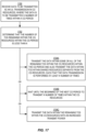
- a method performed by a New Radio (NR) base station comprises monitoring UL transmissions by a wireless device in CG resources, the data to be transmitted K number of times within a CG period, detecting that the wireless device is transmitting on CG resources, determining that a number of TOs within the CG resources and within a CG period for the wireless device for transmitting the data will be less than K, and monitoring a shared resource, which is different than the CG resources, for GF transmissions of the data by the wireless device.
- NR New Radio
- the CG period for the shared resources is either aligned with the CG period for the CG resources or offset or delayed in time relative to the CG period for the CG resources.
- the TOs within the CG resources and the shared resources are contiguous with each other in the time domain or are not contiguous with each other in the time domain.
- the CG period for the shared resources is offset relative to the CG period for the CG resources.
- the CG period for the shared resources does not begin until on or after the end of the CG period for the CG resources.
- determining that that the number of TOs within the CG resources and within a CG period for the wireless device will be less than K further comprises determining that the number of TOs remaining within the CG resources and within a CG period for the wireless device is less than a threshold T.
- the method further comprises determining whether to perform detection on the CG resources or on the shared resources based upon the value of T.
- the method further comprises detecting one or more GF transmissions of the data on the shared resource by the wireless device.
- a wireless device for operating in a 5G network, the wireless device comprising processing circuitry configured to perform any of the steps of any of the wireless device methods disclosed herein, and power supply circuitry configured to supply power to the wireless device.
- a base station operating in a 5G network comprising processing circuitry configured to perform any of the steps of any of the base station methods disclosed herein, and power supply circuitry configured to supply power to the base station.
- Certain embodiments may provide one or more of the following technical advantage(s). These advantages include having an assistive shared resource pool or SUL that can ensure K repetitions or transmission reliability; this approach can be better than multiple CGs as the latter may lead to high resource wastage than a shared resource allocation.
- the present disclosure targets reliability enhancement for CG User Equipments (UEs) where a UE tries to ensure K repetitions by transmitting some or all repetitions in shared resource (pool) or Supplemental Uplink (SUL) carrier in a GF manner when the UE is unable to transmit in a sufficient number of CG Transmission Occasions (TOs).
- UEs User Equipments
- SUL Supplemental Uplink
- Transmissions in the shared pool or SUL can be performed randomly or with some semi-deterministic or fully deterministic pattern.
- the shared resource acts as an assistive resource to CG.
- Allocation of a shared resource alongside CG resources can ensure K repetitions or the equivalent: recognizing that the shared resources may have lower reliability than the CG resources, allocation of shared resources can support additional repetitions which could help to achieve at least the targeted reliability which could have otherwise been achieved with K repetitions alone in CG resources. Therefore, the total number of repetitions within the CG resources and the shared resources may be a number greater than K.
- the CG period within the shared resource may be aligned with, or offset from, the CG period within the CG resources.
- a UE transmitting with repetitions less than the K TOs in the CG can implement dynamic power control for such repetitions to achieve the target reliability.
- Radio Node As used herein, a "radio node” is either a radio access node or a wireless device.
- Radio Access Node As used herein, a "radio access node” or “radio network node” is any node in a radio access network of a cellular communications network that operates to wirelessly transmit and/or receive signals.
- a radio access node include, but are not limited to, a base station (e.g., a New Radio (NR) base station (gNB) in a Third Generation Partnership Project (3GPP) Fifth Generation (5G) NR network or an enhanced or evolved Node B (eNB) in a 3GPP Long Term Evolution (LTE) network), a high-power or macro base station, a low-power base station (e.g., a micro base station, a pico base station, a home eNB, or the like), and a relay node.
- a base station e.g., a New Radio (NR) base station (gNB) in a Third Generation Partnership Project (3GPP) Fifth Generation (5G) NR network or an enhanced or evolved Node B (eNB) in a
- a "core network node” is any type of node in a core network.
- Some examples of a core network node include, e.g., a Mobility Management Entity (MME), a Packet Data Network Gateway (P-GW), a Service Capability Exposure Function (SCEF), or the like.
- MME Mobility Management Entity
- P-GW Packet Data Network Gateway
- SCEF Service Capability Exposure Function
- a “wireless device” is any type of device that has access to (i.e., is served by) a cellular communications network by wirelessly transmitting and/or receiving signals to a radio access node(s).
- a wireless device include, but are not limited to, a User Equipment device (UE) in a 3GPP network and a Machine Type Communication (MTC) device.
- UE User Equipment device
- MTC Machine Type Communication
- Network Node As used herein, a "network node” is any node that is either part of the radio access network or the core network of a cellular communications network/system.
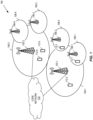
- FIG. 1 illustrates one example of a cellular communications network 100 according to some embodiments of the present disclosure.
- the cellular communications network 100 is a 5G NR network.
- the cellular communications network 100 includes base stations 102-1 and 102-2, which in LTE are referred to as eNBs and in 5G NR are referred to as gNBs, controlling corresponding macro cells 104-1 and 104-2.
- the base stations 102-1 and 102-2 are generally referred to herein collectively as base stations 102 and individually as base station 102.
- the macro cells 104-1 and 104-2 are generally referred to herein collectively as macro cells 104 and individually as macro cell 104.
- the cellular communications network 100 may also include a number of low power nodes 106-1 through 106-4 controlling corresponding small cells 108-1 through 108-4.
- the low power nodes 106-1 through 106-4 can be small base stations (such as pico or femto base stations) or Remote Radio Heads (RRHs), or the like.
- RRHs Remote Radio Heads
- one or more of the small cells 108-1 through 108-4 may alternatively be provided by the base stations 102.
- the low power nodes 106-1 through 106-4 are generally referred to herein collectively as low power nodes 106 and individually as low power node 106.
- the small cells 108-1 through 108-4 are generally referred to herein collectively as small cells 108 and individually as small cell 108.
- the base stations 102 (and optionally the low power nodes 106) are connected to a core network 110.
- the base stations 102 and the low power nodes 106 provide service to wireless devices 112-1 through 112-5 in the corresponding cells 104 and 108.
- the wireless devices 112-1 through 112-5 are generally referred to herein collectively as wireless devices 112 and individually as wireless device 112.
- the wireless devices 112 are also sometimes referred to herein as UEs.
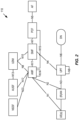
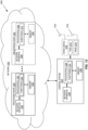
- Figure 2 illustrates a wireless communication system represented as a 5G network architecture composed of core Network Functions (NFs), where interaction between any two NFs is represented by a point-to-point reference point/interface.
- Figure 2 can be viewed as one particular implementation of the system 100 of Figure 1 .
- NFs Network Functions
- the 5G network architecture shown in Figure 2 comprises a plurality of UEs connected to either a Radio Access Network (RAN) or an Access Network (AN) as well as an Access and Mobility Management Function (AMF).
- the R(AN) comprises base stations, e.g., such as evolved Node Bs (eNBs) or NR base stations (gNBs) or similar.
- the 5G core NFs shown in Figure 2 include a Network Slice Selection Function (NSSF), an Authentication Server Function (AUSF), a Unified Data Management (UDM), an AMF, a Session Management Function (SMF), a Policy Control Function (PCF), and an Application Function (AF).
- NSSF Network Slice Selection Function
- AUSF Authentication Server Function
- UDM Unified Data Management
- AMF Policy Control Function
- AF Application Function
- the N1 reference point is defined to carry signaling between the UE and AMF.
- the reference points for connecting between the AN and AMF and between the AN and UPF are defined as N2 and N3, respectively.
- N4 is used by the SMF and UPF so that the UPF can be set using the control signal generated by the SMF, and the UPF can report its state to the SMF.
- N9 is the reference point for the connection between different UPFs
- N14 is the reference point connecting between different AMFs, respectively.
- N15 and N7 are defined since the PCF applies policy to the AMF and SMP, respectively.
- N12 is required for the AMF to perform authentication of the UE.
- N8 and N10 are defined because the subscription data of the UE is required for the AMF and SMF.
- the 5G core network aims at separating user plane and control plane.
- the user plane carries user traffic while the control plane carries signaling in the network.
- the UPF is in the user plane and all other NFs, i.e., the AMF, SMF, PCF, AF, AUSF, and UDM, are in the control plane. Separating the user and control planes guarantees each plane resource to be scaled independently. It also allows UPFs to be deployed separately from control plane functions in a distributed fashion. In this architecture, UPFs may be deployed very close to UEs to shorten the Round Trip Time (RTT) between UEs and data network for some applications requiring low latency.
- RTT Round Trip Time
- the core 5G network architecture is composed of modularized functions.
- the AMF and SMF are independent functions in the control plane. Separated AMF and SMF allow independent evolution and scaling.
- Other control plane functions like the PCF and AUSF can be separated as shown in Figure 2 .
- Modularized function design enables the 5G core network to support various services flexibly.
- Each NF interacts with another NF directly. It is possible to use intermediate functions to route messages from one NF to another NF.
- a set of interactions between two NFs is defined as service so that its reuse is possible. This service enables support for modularity.
- the user plane supports interactions such as forwarding operations between different UPFs.
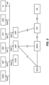
- Figure 3 illustrates a 5G network architecture using service-based interfaces between the NFs in the control plane, instead of the point-to-point reference points/interfaces used in the 5G network architecture of Figure 2 .
- the NFs described above with reference to Figure 2 correspond to the NFs shown in Figure 3 .
- the service(s) etc. that a NF provides to other authorized NFs can be exposed to the authorized NFs through the service-based interface.
- the service based interfaces are indicated by the letter "N" followed by the name of the NF, e.g., Namf for the service based interface of the AMF and Nsmf for the service based interface of the SMF etc.
- NEF Network Exposure Function
- NRF Network Repository Function
- the AMF provides UE-based authentication, authorization, mobility management, etc.
- a UE even using multiple access technologies is basically connected to a single AMF because the AMF is independent of the access technologies.
- the SMF is responsible for session management and allocates Internet Protocol (IP) addresses to UEs. It also selects and controls the UPF for data transfer. If a UE has multiple sessions, different SMFs may be allocated to each session to manage them individually and possibly provide different functionalities per session.
- the AF provides information on the packet flow to the PCF responsible for policy control in order to support Quality of Service (QoS). Based on the information, the PCF determines policies about mobility and session management to make the AMF and SMF operate properly.
- the AUSF supports authentication function for UEs or similar and thus stores data for authentication of UEs or similar while the UDM stores subscription data of the UE.
- the Data Network (DN) not part of the 5G core network, provides Internet access or operator services and similar.
- An NF may be implemented either as a network element on a dedicated hardware, as a software instance running on a dedicated hardware, or as a virtualized function instantiated on an appropriate platform, e.g., a cloud infrastructure.
- a UE can use specific resources (e.g., periodical time-frequency resource) in a period of a CG to ensure its K repetition. However, if a UE misses its one or more transmission opportunities, e.g., because its traffic arrives late in the period, the UE then utilizes the remaining transmission opportunities. If the number of remaining TOs within CG resources is ⁇ K , the UE cannot ensure its K repetition transmission. To ensure K repetition transmission, some embodiments allocate a separate shared resource pool where a UE can transmit the rest of the repetitions which it may be unable to transmit within a period of CG.
- the shared resource can be, for example, a common Physical Uplink Shared Channel (PUSCH) resource.
- the data transmissions in the shared resource may be GF transmissions. Transmissions in the shared pool or SUL can be performed randomly or with some semi-deterministic or fully deterministic pattern.
- the target is K transmissions in CG resource to achieve given reliability
- Y transmissions should occur in the shared resource.
- the UE may transmit Y + N transmissions in the shared resource (where N ⁇ 1), so that even if some of the Y + N transmissions fail (e.g., due to collisions with transmissions from another UE also using the shared resource), there will still be Y transmissions that succeed, thus meeting the target total number of K transmissions.
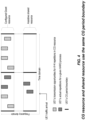
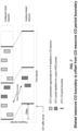
- Figure 4 illustrates the use of TOs within a shared resource to provide additional TOs sufficient to ensure that K repetitions are performed, according to some embodiments of the present disclosure in which the CG period boundary for the CG resource is aligned with the CG period boundary for the shared resource.
- the UE can utilize any resource (e.g., in case of random access) from a predefined resource pool or UE-specific transmission pattern within the shared resource pool.
- both the CG resources and the shared resource pool have the same CG period boundaries in the time domain because repetitions belonging to a Hybrid Automatic Repeat Request (HARQ) process are transmitted within a period that is used by both the CG resources and the shared resource pool.
- HARQ Hybrid Automatic Repeat Request
- Figure 5 illustrates a scenario where two UEs, called UE1 and UE2, attempt to put repetitions into the shared resource and in which one of the repetitions for UE1 collides with one of the repetitions for UE2 in the shared resource.
- Figure 5 illustrates the point that transmissions in the shared resource are more likely to suffer collisions than those in the CG resources and are therefore less reliable than transmissions in the CG resources.
- Figures 4 and 5 illustrate embodiments where the TOs in the CG resources and the shared resource pool (and therefore the actual repetitions also) are not contiguous, e.g., there is a gap of time between them.
- the repetitions may include a time-gap between the TOs.
- FIG. 6 illustrates an embodiment in which the TOs are contiguous in the time domain.
- the TOs are not only contiguous in the CG resources and contiguous in the shared resources, but the combined TOs are contiguous in the time domain.
- the CG period boundary within the shared resource is not aligned with the CG period boundary of the CG resource, but instead offset from the CG period boundary of the CG resource. This is illustrated in Figure 7 .
- Figure 7 illustrates the use of TOs within a shared resource to provide additional TOs sufficient to ensure that K repetitions are performed, according to some embodiments of the present disclosure in which the CG period boundary for the CG resource is aligned with the CG period boundary for the shared resource.
- the shared resource's periodical boundary is set at a given offset with respect to the boundary of a CG's period. This provides the advantage that a UE can schedule the additional actual repetitions in the shared resource later in time (compared to the actual repetitions in the CG resource) yet still remain within the same CG boundary and thus within the same HARQ process. Since the transmission on the shared resources occupies the same HARQ process, it can use the same signature that was used for the actual repetitions in the CG resources. This benefit is illustrated more clearly in Figure 8 .
- Figure 8 illustrates the use of TOs within a shared resource to provide additional TOs sufficient to ensure that K repetitions are performed, according to some embodiments of the present disclosure in which the CG period boundary for the CG resource is aligned with the CG period boundary for the shared resource.
- Figure 8 illustrates the point that, because the CG period boundary for the shared resource is offset relative to the CG period boundary of the CG resource, all of the repetitions desired for the first HARQ process, "HARQ process X,” can be transmitted in the shared resource without interfering with the repetitions for the next HARQ process, "HARQ process X+1," and without requiring an additional signature.
- the offset gives the UE some more time to fulfill the repetitions for one HARQ process before the CG period for that HARQ has expired.
- the offset value can be sent using Downlink Control Information (DCI) or Radio Resource Control (RRC) messages.
- DCI Downlink Control Information
- RRC Radio Resource Control
- Figure 9 illustrates an embodiment in which the TOs are contiguous in the time domain and where the CG period for the shared resource is offset relative to the CG period in the CG resource.
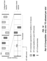
- Figure 10 illustrates the use of TOs within a shared resource to provide additional TOs sufficient to ensure that K repetitions are performed, according to some embodiments of the present disclosure in which only one TO or mini-slot for a repetition is allowed per slot.
- the UE cannot put a repetition for the same HARQ into both the CG resources and the shared resources during the same time slot. Since there is no opportunity to put more than one repetition for the same HARQ into any slot, an offset equivalent to ⁇ K slots would be helpful to transmit the rest of the repetitions in the shared resource.
- one repetition per time slot may apply only to a particular HARQ process, in which case a UE is allowed to transmit a TO for a first HARQ process within the shared resources and a TO for a second HARQ within the CG resources, within the same time slot. This is illustrated in Figure 11 .
- Figure 11 illustrates the use of TOs within a shared resource to provide additional TOs sufficient to ensure that K repetitions are performed, according to some embodiments of the present disclosure in which only one TO or mini-slot for a repetition is allowed per slot per HARQ process.
- the gNB may be required to monitor these M UEs constantly in the shared resource. For example, the gNB may need to perform blind decoding of at least a portion of the shared resources. To reduce this burden, following techniques may be used. The UE will check the shared resource if the UE detects the transmission or senses the energy in the CG, and, in some embodiments, try to identify only those UEs in the shared resource if their repetitions are done partially in the CG.
- the gNB may ensure that majority of the repetitions should occur in the CG as the CG resource is more reliable than shared resource;
- Figure 5 shows that there may be collisions within the shared resource. For example, if the traffic arrives close to end of the period, UE should rather start transmitting in the next period (if latency is not impacted) instead of transmitting in the current period with rest of the repetitions in the shared resource.
- K threshold ceil(K/2).
- the activation DCI has the "Uplink (UL) /SUL indicator" field of value '0,' which indicates the non-supplementary uplink.
- the PUSCH stays on the non-SUL carrier.
- the UE switches the PUSCH transmission to the SUL carrier on its own (i.e., without a signal from the gNB). Since the SUL carrier tends to have lower carrier frequency and allow more reliable UL transmission, switching to the SUL carrier improves PUSCH reliability.
- BPRE Bits Per Resource Element
- the power control based method has the benefit of no impact to gNB reception of PUSCH.
- the potential deficiency is that a UE may not be able to increase its transmit power, e.g., when the UE is already operating at maximum power allowed for the PUSCH.
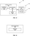
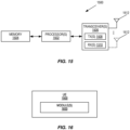
- FIG. 12 is a schematic block diagram of a network node 1200 according to some embodiments of the present disclosure.
- the network node 1200 may be, for example, a radio access node, such as a base station 102 or 106.
- the network node 1200 includes a control system 1202 that includes one or more processors 1204 (e.g., Central Processing Units (CPUs), Application Specific Integrated Circuits (ASICs), Field Programmable Gate Arrays (FPGAs), and/or the like), memory 1206, and a network interface 1208.
- the one or more processors 1204 are also referred to herein as processing circuitry.
- the network node 1200 may include one or more radio units 1210 that each includes one or more transmitters 1212 and one or more receivers 1214 coupled to one or more antennas 1216.
- the radio units 1210 may be referred to or be part of radio interface circuitry.
- the radio unit(s) 1210 is external to the control system 1202 and connected to the control system 1202 via, e.g., a wired connection (e.g., an optical cable).
- the radio unit(s) 1210 and potentially the antenna(s) 1216 are integrated together with the control system 1202.
- the one or more processors 1204 operate to provide one or more functions of a network node 1200 as described herein.
- the function(s) are implemented in software that is stored, e.g., in the memory 1206 and executed by the one or more processors 1204.
- Figure 13 is a schematic block diagram that illustrates a virtualized embodiment of the network node 1200 according to some embodiments of the present disclosure. This discussion is equally applicable to other types of network nodes. Further, other types of network nodes may have similar virtualized architectures.
- a "virtualized" network node is an implementation of the network node 1200 in which at least a portion of the functionality of the network node 1200 is implemented as a virtual component(s) (e.g., via a virtual machine(s) executing on a physical processing node(s) in a network(s)).
- the network node 1200 includes the control system 1202 that includes the one or more processors 1204 (e.g., CPUs, ASICs, FPGAs, and/or the like), the memory 1206, and the network interface 1208 and the one or more radio units 1210 that each includes the one or more transmitters 1212 and the one or more receivers 1214 coupled to the one or more antennas 1216, as described above.
- the control system 1202 is connected to the radio unit(s) 1210 via, for example, an optical cable or the like.
- the control system 1202 is connected to one or more processing nodes 1300 coupled to or included as part of a network(s) 1302 via the network interface 1208.
- Each processing node 1300 includes one or more processors 1304 (e.g., CPUs, ASICs, FPGAs, and/or the like), memory 1306, and a network interface 1308.
- functions 1310 of the network node 1200 described herein are implemented at the one or more processing nodes 1300 or distributed across the control system 1202 and the one or more processing nodes 1300 in any desired manner.
- some or all of the functions 1310 of the network node 1200 described herein are implemented as virtual components executed by one or more virtual machines implemented in a virtual environment(s) hosted by the processing node(s) 1300.
- additional signaling or communication between the processing node(s) 1300 and the control system 1202 is used in order to carry out at least some of the desired functions 1310.
- the control system 1202 may not be included, in which case the radio unit(s) 1210 communicate directly with the processing node(s) 1300 via an appropriate network interface(s).
- a computer program including instructions which, when executed by at least one processor, causes the at least one processor to carry out the functionality of the network node 1200 or a node (e.g., a processing node 1300) implementing one or more of the functions 1310 of the network node 1200 in a virtual environment according to any of the embodiments described herein is provided.
- a carrier comprising the aforementioned computer program product is provided. The carrier is one of an electronic signal, an optical signal, a radio signal, or a computer readable storage medium (e.g., a non-transitory computer readable medium such as memory).
- FIG 14 is a schematic block diagram of the network node 1200 according to some other embodiments of the present disclosure.
- the network node 1200 includes one or more modules 1400, each of which is implemented in software.
- the module(s) 1400 provide the functionality of the network node 1200 described herein. This discussion is equally applicable to the processing node 1300 of Figure 13 where the modules 1400 may be implemented at one of the processing nodes 1300 or distributed across multiple processing nodes 1300 and/or distributed across the processing node(s) 1300 and the control system 1202.
- FIG. 15 is a schematic block diagram of a UE 1500 according to some embodiments of the present disclosure.
- the UE 1500 includes one or more processors 1502 (e.g., CPUs, ASICs, FPGAs, and/or the like), memory 1504, and one or more transceivers 1506 each including one or more transmitters 1508 and one or more receivers 1510 coupled to one or more antennas 1512.
- the transceiver(s) 1506 includes radio-front end circuitry connected to the antenna(s) 1512 that is configured to condition signals communicated between the antenna(s) 1512 and the processor(s) 1502, as will be appreciated by on of ordinary skill in the art.
- the processors 1502 are also referred to herein as processing circuitry.
- the transceivers 1506 are also referred to herein as radio circuitry.
- the functionality of the UE 1500 described above may be fully or partially implemented in software that is, e.g., stored in the memory 1504 and executed by the processor(s) 1502.
- the UE 1500 may include additional components not illustrated in Figure 15 such as, e.g., one or more user interface components (e.g., an input/output interface including a display, buttons, a touch screen, a microphone, a speaker(s), and/or the like and/or any other components for allowing input of information into the UE 1500 and/or allowing output of information from the UE 1500), a power supply (e.g., a battery and associated power circuitry), etc.
- a power supply e.g., a battery and associated power circuitry
- a computer program including instructions which, when executed by at least one processor, causes the at least one processor to carry out the functionality of the UE 1500 according to any of the embodiments described herein is provided.
- a carrier comprising the aforementioned computer program product is provided.
- the carrier is one of an electronic signal, an optical signal, a radio signal, or a computer readable storage medium (e.g., a non-transitory computer readable medium such as memory).
- FIG 16 is a schematic block diagram of the UE 1500 according to some other embodiments of the present disclosure.
- the UE 1500 includes one or more modules 1600, each of which is implemented in software.
- the module(s) 1600 provide the functionality of the UE 1500 described herein.
- Figure 17 is a flowchart illustrating a method performed by a UE operating in a 5G network according to some embodiments of the present disclosure. In the embodiment illustrated in Figure 17 , the method includes the following steps:
- a UE receives data to be transmitted as an UL transmission in CG resources, where the data is to be transmitted K number of times within the CG period.
- the UE's transceiver receives the data from a higher layer (e.g., from an application layer entity) within the UE itself.
- Data transmitted in CG resources is usually GF, but the present subject matter is not limited to only GF transmissions.
- the same data content is being transmitted multiple times, but the specific form or representation of that data might or might not vary.
- the form of the data being transmitted multiple times may vary (e.g., different encoding) due to redundancy level considerations.
- the form of the data may be exactly the same for each of the multiple transmissions.
- the UE determines that the number of TOs remaining within the CG resources within the CG period for the UE is less than K. For example, the UE may not receive the data to be UL transmitted until well within a current CG period; since the UE knows the location of the TOs within CG periods, the UE can determine based on the arrival time of the data how many TOs within the current CG period have already passed and which the UE therefore cannot use.
- one of the TOs that the UE intended to use for first data to be UL transmitted may be preempted, e.g., by second data that has higher priority; the UE can determine that there are not enough remaining TOs to meet the required K number of transmissions for the first data.
- TDD Time Division Duplexing
- a UE may be unable to use all TOs for an UL transmission because some of them occur during a Downlink (DL) TDD portion.
- the UE takes action to mitigate the insufficiency of remaining TOs necessary to meet the required K number of transmissions.
- the UE transmits the data using some or all of the remaining TOs within the CG resources and also transmits the data using TOs within shared resources, which are different from the CG resources, such that the transmission is repeated performed K number of times (step 1704A).
- the UE waits until the beginning of the next CG period to transmit K number of times using the CG resources (step 1704B).
- the UE transmits the data using the remaining TOs within the CG resources, but with increased transmit power in order to increase the likelihood of a successful reception by the gNB or other intended recipient (step 1704C).
- the techniques above may also be combined, e.g., the UE may transmit using CG resources and also using shared resources, with transmissions in either or both at increased transmit power.
- Figure 18 is a flowchart illustrating a method performed by a NR base station, or gNB, according to some embodiments of the present disclosure. In the embodiment illustrated in Figure 18 , the method includes the following steps:
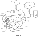
- FIG. 19 illustrates a communication system according to some embodiments of the present disclosure.
- a communication system includes a telecommunication network 1900, such as a 3GPP-type cellular network, which comprises an access network 1902, such as a RAN, and a core network 1904.
- the access network 1902 comprises a plurality of base stations 1906A, 1906B, 1906C, such as NBs, eNBs, gNBs, or other types of wireless Access Points (APs), each defining a corresponding coverage area 1908A, 1908B, 1908C.
- Each base station 1906A, 1906B, 1906C is connectable to the core network 1904 over a wired or wireless connection 1910.
- a first UE 1912 located in coverage area 1908C is configured to wirelessly connect to, or be paged by, the corresponding base station 1906C.
- a second UE 1914 in coverage area 1908A is wirelessly connectable to the corresponding base station 1906A. While a plurality of UEs 1912, 1914 are illustrated in this example, the disclosed embodiments are equally applicable to a situation where a sole UE is in the coverage area or where a sole UE is connecting to the corresponding base station 1906.
- the telecommunication network 1900 is itself connected to a host computer 1916, which may be embodied in the hardware and/or software of a standalone server, a cloud-implemented server, a distributed server, or as processing resources in a server farm.
- the host computer 1916 may be under the ownership or control of a service provider, or may be operated by the service provider or on behalf of the service provider.
- Connections 1918 and 1920 between the telecommunication network 1900 and the host computer 1916 may extend directly from the core network 1904 to the host computer 1916 or may go via an optional intermediate network 1922.
- the intermediate network 1922 may be one of, or a combination of more than one of, a public, private, or hosted network; the intermediate network 1922, if any, may be a backbone network or the Internet; in particular, the intermediate network 1922 may comprise two or more sub-networks (not shown).
- the communication system of Figure 19 as a whole enables connectivity between the connected UEs 1912, 1914 and the host computer 1916.
- the connectivity may be described as an Over-the-Top (OTT) connection 1924.
- the host computer 1916 and the connected UEs 1912, 1914 are configured to communicate data and/or signaling via the OTT connection 1924, using the access network 1902, the core network 1904, any intermediate network 1922, and possible further infrastructure (not shown) as intermediaries.
- the OTT connection 1924 may be transparent in the sense that the participating communication devices through which the OTT connection 1924 passes are unaware of routing of uplink and downlink communications.
- the base station 1906 may not or need not be informed about the past routing of an incoming downlink communication with data originating from the host computer 1916 to be forwarded (e.g., handed over) to a connected UE 1912. Similarly, the base station 1906 need not be aware of the future routing of an outgoing uplink communication originating from the UE 1912 towards the host computer 1916.
- FIG. 20 illustrates a communication system according to some embodiments of the present disclosure.
- Example implementations, in accordance with an embodiment, of the UE, base station, and host computer discussed in the preceding paragraphs will now be described with reference to Figure 20 .
- a host computer 2002 comprises hardware 2004 including a communication interface 2006 configured to set up and maintain a wired or wireless connection with an interface of a different communication device of the communication system 2000.
- the host computer 2002 further comprises processing circuitry 2008, which may have storage and/or processing capabilities.
- the processing circuitry 2008 may comprise one or more programmable processors, ASICs, FPGAs, or combinations of these (not shown) adapted to execute instructions.
- the host computer 2002 further comprises software 2010, which is stored in or accessible by the host computer 2002 and executable by the processing circuitry 2008.
- the software 2010 includes a host application 2012.
- the host application 2012 may be operable to provide a service to a remote user, such as a UE 2014 connecting via an OTT connection 2016 terminating at the UE 2014 and the host computer 2002. In providing the service to the remote user, the host application 2012 may provide user data which is transmitted using the OTT connection 2016.
- the communication system 2000 further includes a base station 2018 provided in a telecommunication system and comprising hardware 2020 enabling it to communicate with the host computer 2002 and with the UE 2014.
- the hardware 2020 may include a communication interface 2022 for setting up and maintaining a wired or wireless connection with an interface of a different communication device of the communication system 2000, as well as a radio interface 2024 for setting up and maintaining at least a wireless connection 2026 with the UE 2014 located in a coverage area (not shown in Figure 20 ) served by the base station 2018.
- the communication interface 2022 may be configured to facilitate a connection 2028 to the host computer 2002.
- the connection 2028 may be direct or it may pass through a core network (not shown in Figure 20 ) of the telecommunication system and/or through one or more intermediate networks outside the telecommunication system.
- the hardware 2020 of the base station 2018 further includes processing circuitry 2030, which may comprise one or more programmable processors, ASICs, FPGAs, or combinations of these (not shown) adapted to execute instructions.
- the base station 2018 further has software 2032 stored internally or accessible via an external connection.
- the communication system 2000 further includes the UE 2014 already referred to.
- the UE's 2014 hardware 2034 may include a radio interface 2036 configured to set up and maintain a wireless connection 2026 with a base station serving a coverage area in which the UE 2014 is currently located.
- the hardware 2034 of the UE 2014 further includes processing circuitry 2038, which may comprise one or more programmable processors, ASICs, FPGAs, or combinations of these (not shown) adapted to execute instructions.
- the UE 2014 further comprises software 2040, which is stored in or accessible by the UE 2014 and executable by the processing circuitry 2038.
- the software 2040 includes a client application 2042.
- the client application 2042 may be operable to provide a service to a human or non-human user via the UE 2014, with the support of the host computer 2002.
- the executing host application 2012 may communicate with the executing client application 2042 via the OTT connection 2016 terminating at the UE 2014 and the host computer 2002.
- the client application 2042 may receive request data from the host application 2012 and provide user data in response to the request data.
- the OTT connection 2016 may transfer both the request data and the user data.
- the client application 2042 may interact with the user to generate the user data that it provides.
- the host computer 2002, the base station 2018, and the UE 2014 illustrated in Figure 20 may be similar or identical to the host computer 1916, one of the base stations 1906A, 1906B, 1906C, and one of the UEs 1912, 1914 of Figure 19 , respectively.
- the inner workings of these entities may be as shown in Figure 20 and independently, the surrounding network topology may be that of Figure 19 .
- the OTT connection 2016 has been drawn abstractly to illustrate the communication between the host computer 2002 and the UE 2014 via the base station 2018 without explicit reference to any intermediary devices and the precise routing of messages via these devices.
- the network infrastructure may determine the routing, which may be configured to hide from the UE 2014 or from the service provider operating the host computer 2002, or both. While the OTT connection 2016 is active, the network infrastructure may further take decisions by which it dynamically changes the routing (e.g., on the basis of load balancing consideration or reconfiguration of the network).
- the wireless connection 2026 between the UE 2014 and the base station 2018 is in accordance with the teachings of the embodiments described throughout this disclosure.
- One or more of the various embodiments improve the performance of OTT services provided to the UE 2014 using the OTT connection 2016, in which the wireless connection 2026 forms the last segment. More precisely, the teachings of these embodiments provide additional opportunities for transmission repetitions and thereby provide benefits such as increased reliability for URLLC transmissions.
- a measurement procedure may be provided for the purpose of monitoring data rate, latency, and other factors on which the one or more embodiments improve.
- the measurement procedure and/or the network functionality for reconfiguring the OTT connection 2016 may be implemented in the software 2010 and the hardware 2004 of the host computer 2002 or in the software 2040 and the hardware 2034 of the UE 2014, or both.
- sensors may be deployed in or in association with communication devices through which the OTT connection 2016 passes; the sensors may participate in the measurement procedure by supplying values of the monitored quantities exemplified above, or supplying values of other physical quantities from which the software 2010, 2040 may compute or estimate the monitored quantities.
- the reconfiguring of the OTT connection 2016 may include message format, retransmission settings, preferred routing, etc.; the reconfiguring need not affect the base station 2018, and it may be unknown or imperceptible to the base station 2018. Such procedures and functionalities may be known and practiced in the art.
- measurements may involve proprietary UE signaling facilitating the host computer 2002's measurements of throughput, propagation times, latency, and the like. The measurements may be implemented in that the software 2010 and 2040 causes messages to be transmitted, in particular empty or 'dummy' messages, using the OTT connection 2016 while it monitors propagation times, errors, etc.
- FIG. 21 is a flowchart illustrating a method implemented in a communication system, in accordance with some embodiments of the present disclosure.
- the communication system includes a host computer, a base station, and a UE which may be those described with reference to Figures 19 and 20 .
- the host computer provides user data.
- sub-step 2102 (which may be optional) of step 2100, the host computer provides the user data by executing a host application.
- step 2104 the host computer initiates a transmission carrying the user data to the UE.
- step 2106 the base station transmits to the UE the user data which was carried in the transmission that the host computer initiated, in accordance with the teachings of the embodiments described throughout this disclosure.
- step 2108 the UE executes a client application associated with the host application executed by the host computer.
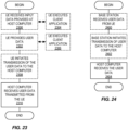
- FIG 22 is a flowchart illustrating a method implemented in a communication system, in accordance with some embodiments of the present disclosure.
- the communication system includes a host computer, a base station, and a UE which may be those described with reference to Figures 19 and 20 .
- the host computer provides user data.
- the host computer provides the user data by executing a host application.
- the host computer initiates a transmission carrying the user data to the UE.
- the transmission may pass via the base station, in accordance with the teachings of the embodiments described throughout this disclosure.
- step 2204 (which may be optional), the UE receives the user data carried in the transmission.
- FIG 23 is a flowchart illustrating a method implemented in a communication system, in accordance with some embodiments of the present disclosure.
- the communication system includes a host computer, a base station, and a UE which may be those described with reference to Figures 19 and 20 .
- the UE receives input data provided by the host computer. Additionally or alternatively, in step 2302, the UE provides user data.
- sub-step 2304 (which may be optional) of step 2300, the UE provides the user data by executing a client application.
- sub-step 2306 (which may be optional) of step 2302, the UE executes a client application which provides the user data in reaction to the received input data provided by the host computer.
- the executed client application may further consider user input received from the user.
- the UE initiates, in sub-step 2308 (which may be optional), transmission of the user data to the host computer.
- the host computer receives the user data transmitted from the UE, in accordance with the teachings of the embodiments described throughout this disclosure.
- FIG. 24 is a flowchart illustrating a method implemented in a communication system, in accordance with some embodiments of the present disclosure.
- the communication system includes a host computer, a base station, and a UE which may be those described with reference to Figures 19 and 20 .
- the base station receives user data from the UE.
- the base station initiates transmission of the received user data to the host computer.
- the host computer receives the user data carried in the transmission initiated by the base station.
- any appropriate steps, methods, features, functions, or benefits disclosed herein may be performed through one or more functional units or modules of one or more virtual apparatuses.
- Each virtual apparatus may comprise a number of these functional units.
- These functional units may be implemented via processing circuitry, which may include one or more microprocessor or microcontrollers, as well as other digital hardware, which may include Digital Signal Processor (DSPs), special-purpose digital logic, and the like.
- the processing circuitry may be configured to execute program code stored in memory, which may include one or several types of memory such as Read Only Memory (ROM), Random Access Memory (RAM), cache memory, flash memory devices, optical storage devices, etc.
- Program code stored in memory includes program instructions for executing one or more telecommunications and/or data communications protocols as well as instructions for carrying out one or more of the techniques described herein.
- the processing circuitry may be used to cause the respective functional unit to perform corresponding functions according one or more embodiments of the present disclosure.
Claims (16)
- Procédé réalisé par un dispositif sans fil (112), pour fonctionner dans un réseau de cinquième génération, 5G, (100), le procédé comprenant :la réception (1700) de données à transmettre en tant qu'une transmission de liaison montante, UL, dans des ressources d'octroi configuré, CG, les données devant être transmises un nombre K de fois au cours d'une période CG pour les ressources CG ;la détermination (1702) qu'un nombre d'occasions de transmission, TO, restantes à l'intérieur des ressources CG et au cours de la période CG pour le dispositif sans fil est inférieur à K ; etla transmission (1704A) des données dans les TO restantes à l'intérieur des ressources CG,le procédé étant caractérisé par :
la transmission (1704A) également des données dans des TO à l'intérieur de ressources partagées, qui sont différentes des ressources CG, de sorte que la transmission soit réalisée au moins un nombre K de fois. - Procédé selon la revendication 1, dans lequel une période CG pour les ressources partagées est :soit alignée avec la période CG pour les ressources CG ;soit décalée ou retardée dans le temps par rapport à la période CG pour les ressources CG.
- Procédé selon la revendication 2, dans lequel les TO à l'intérieur des ressources CG et des ressources partagées sont :contigües les unes aux autres dans un domaine de temps ; oune sont pas contiguës les unes aux autres dans le domaine de temps.
- Procédé selon la revendication 2 ou 3, dans lequel il n'y a qu'une TO par créneau de temps par processus de demande de répétition automatique hybride, HARQ.
- Procédé selon l'une quelconque des revendications 2 à 4, dans lequel la transmission des données dans les TO à l'intérieur des ressources partagées comprend la transmission des données à un emplacement qui est choisi aléatoirement, de manière déterministe ou de manière semi-déterministe.
- Procédé selon l'une quelconque des revendications 2 à 5, dans lequel la transmission des données dans les TO à l'intérieur des ressources partagées de sorte que la transmission soit réalisée au moins un nombre K de fois comprend la réalisation de la transmission un nombre L de fois, où L > K.
- Procédé selon la revendication 6, dans lequel une valeur de L est déterminée sur la base d'une fiabilité des ressources partagées.
- Procédé selon l'une quelconque des revendications précédentes, dans lequel la transmission à l'intérieur des ressources CG, des ressources partagées ou de l'ensemble d'entre elles se déroule à une puissance de transmission accrue.
- Procédé réalisé par une station de base nouvelle radio, NR, gNB, (102), le procédé comprenant :la surveillance (1800) de transmissions de liaison montante, UL, par un dispositif sans fil (112) dans des ressources d'octroi configuré, CG, pour des données à transmettre un nombre K de fois au cours d'une période CG pour les ressources CG ;la détection (1802) que le dispositif sans fil est en train de transmettre sur des ressources CG ;la détermination (1804) qu'un nombre d'occasions de transmission, TO, à l'intérieur des ressources CG et au cours de la période CG pour le dispositif sans fil pour transmettre les données sera inférieur à K ; et le procédé étant caractérisé par :
la surveillance (1806) d'une ressource partagée, qui est différente des ressources CG, pour des transmissions sans octroi, GF, des données par le dispositif sans fil. - Procédé selon la revendication 9, dans lequel une période CG pour les ressources partagées est :soit alignée avec la période CG pour les ressources CG ;soit décalée ou retardée dans le temps par rapport à la période CG pour les ressources CG.
- Procédé selon la revendication 9 ou 10, dans lequel les TO à l'intérieur des ressources CG et des ressources partagées sont :contigües les unes aux autres dans un domaine de temps ;ne sont pas contiguës les unes aux autres dans le domaine de temps.
- Procédé selon l'une quelconque des revendications 9 à 11, dans lequel il n'y a qu'une TO par créneau de temps par processus de demande de répétition automatique hybride, HARQ.
- Procédé selon l'une quelconque des revendications 9 à 12, dans lequel la détermination que le nombre de TO à l'intérieur des ressources CG et au cours de la période CG pour le dispositif sans fil sera inférieur à K comprend en outre la détermination que le nombre de TO restantes à l'intérieur des ressources CG et au cours de la période CG pour le dispositif sans fil est inférieur à un seuil T.
- Dispositif sans fil pour fonctionner dans un réseau de cinquième génération, 5G, le dispositif sans fil comprenant :une circuiterie de fourniture d'énergie configurée pour fournir de l'énergie au dispositif sans fil ; etune circuiterie de traitement configurée pour :recevoir des données à transmettre en tant qu'une transmission de liaison montante, UL, dans des ressources d'octroi configuré, CG, les données devant être transmises un nombre K de fois au cours d'une période CG pour les ressources CG ;déterminer qu'un nombre d'occasions de transmission, TO, restantes à l'intérieur des ressources CG et au cours de la période CG pour le dispositif sans fil est inférieur à K ; ettransmettre les données dans les TO restantes à l'intérieur des ressources CG ; etle dispositif sans fil étant caractérisé en ce que la circuiterie de traitement est configurée pour :
transmettre également les données dans des TO à l'intérieur de ressources partagées, qui sont distinctes des ressources CG. - Dispositif sans fil selon la revendication 14, dans lequel la circuiterie de traitement est configurée pour réaliser le procédé selon l'une quelconque des revendications 2 à 8.
- Station de base fonctionnant dans un réseau de cinquième génération, 5G, la station de base comprenant :une circuiterie de traitement configurée pour réaliser l'une quelconque des revendications 9 à 13 ; etune circuiterie de fourniture d'énergie configurée pour fournir de l'énergie à la station de base.
Applications Claiming Priority (2)
| Application Number | Priority Date | Filing Date | Title |
|---|---|---|---|
| US201962806552P | 2019-02-15 | 2019-02-15 | |
| PCT/SE2020/050155 WO2020167229A1 (fr) | 2019-02-15 | 2020-02-13 | Amélioration de la fiabilité pour un équipement d'utilisateur avec des répétitions partielles dans une autorisation configurée |
Publications (2)
| Publication Number | Publication Date |
|---|---|
| EP3925115A1 EP3925115A1 (fr) | 2021-12-22 |
| EP3925115B1 true EP3925115B1 (fr) | 2023-09-13 |
Family
ID=69726681
Family Applications (1)
| Application Number | Title | Priority Date | Filing Date |
|---|---|---|---|
| EP20708230.6A Active EP3925115B1 (fr) | 2019-02-15 | 2020-02-13 | Amélioration de la fiabilité pour un équipement d'utilisateur avec des répétitions partielles dans une autorisation configurée |
Country Status (3)
| Country | Link |
|---|---|
| US (1) | US11979889B2 (fr) |
| EP (1) | EP3925115B1 (fr) |
| WO (1) | WO2020167229A1 (fr) |
Families Citing this family (2)
| Publication number | Priority date | Publication date | Assignee | Title |
|---|---|---|---|---|
| US11818696B2 (en) * | 2020-04-10 | 2023-11-14 | Qualcomm Incorporated | Techniques for user equipment (UE)-aided selective single frequency network (SFN) in a wireless communication system |
| WO2022041208A1 (fr) * | 2020-08-31 | 2022-03-03 | Qualcomm Incorporated | Autorisation configurée de liaison montante adaptative basée sur une fonction de hachage aléatoire |
Family Cites Families (3)
| Publication number | Priority date | Publication date | Assignee | Title |
|---|---|---|---|---|
| US11540312B2 (en) * | 2018-09-25 | 2022-12-27 | Mediatek Singapore Pte. Ltd. | Method and apparatus for handling multiple active configurations of configured grant in mobile communications |
| WO2020091681A1 (fr) | 2018-11-02 | 2020-05-07 | Telefonaktiebolaget Lm Ericsson (Publ) | Indicateur de détection d'énergie |
| WO2020144015A1 (fr) | 2019-01-11 | 2020-07-16 | Telefonaktiebolaget Lm Ericsson (Publ) | Détection de présence de transmission en liaison montante |
-
2020
- 2020-02-13 EP EP20708230.6A patent/EP3925115B1/fr active Active
- 2020-02-13 US US17/431,317 patent/US11979889B2/en active Active
- 2020-02-13 WO PCT/SE2020/050155 patent/WO2020167229A1/fr unknown
Also Published As
| Publication number | Publication date |
|---|---|
| US11979889B2 (en) | 2024-05-07 |
| EP3925115A1 (fr) | 2021-12-22 |
| US20220167393A1 (en) | 2022-05-26 |
| WO2020167229A1 (fr) | 2020-08-20 |
Similar Documents
| Publication | Publication Date | Title |
|---|---|---|
| JP2019527994A (ja) | チャネルリソース利用率に従った優先トラフィックのためのlte−v2vのための輻輳制御 | |
| US20180139668A1 (en) | Terminal device, base station apparatus, integrated circuit, and wireless communication method | |
| CN113647048B (zh) | 处理服务小区发现突发传输(dbt)窗口中的传输 | |
| EP4193542B1 (fr) | Système et procédés d'amélioration de pucch avec des répétitions intra-fentes vers de multiples trps | |
| JP7460755B2 (ja) | マルチtrp pdsch送信方式のためのtbs決定 | |
| WO2022029721A1 (fr) | Améliorations de la synchronisation associées à une répétition de pucch vers de multiples trp | |
| WO2021205421A1 (fr) | Systèmes et procédés de détermination d'états de tci pour de multiples occasions de transmission | |
| EP3925115B1 (fr) | Amélioration de la fiabilité pour un équipement d'utilisateur avec des répétitions partielles dans une autorisation configurée | |
| WO2022136387A1 (fr) | Mécanisme de surveillance de défaillance et de rétablissement après défaillance dans le cas d'un relais sl | |
| WO2022029711A1 (fr) | Évitement des collisions et/ou traitement des symboles invalides lors de l'utilisation de la répétition du canal de liaison montante vers de multiples trp | |
| WO2021162627A1 (fr) | Gestion de priorisation de liaison montante intra-équipement utilisateur | |
| US20230396373A1 (en) | CONFIGURED GRANT BASED PUSCH TRANSMISSION TO MULTIPLE TRPs | |
| US20240057209A1 (en) | Methods and Devices for Sidelink Transmissions | |
| US20230413320A1 (en) | On ue's transmission configured with multiple channel occupancy time access | |
| WO2022062846A1 (fr) | Procédé et appareil de commutation de trajet | |
| US20230403626A1 (en) | Method and apparatus for relay communication | |
| EP4218352B1 (fr) | Systèmes et procédés de coordination de transmissions de liaison latérale entre des dispositifs sur la base d'un mac ce | |
| US20240064857A1 (en) | Terminal device, network node, and methods therein for drx configuration | |
| WO2022201106A1 (fr) | Détermination de ressources pour tb sur des intervalles multiples | |
| KR20150018209A (ko) | 이동통신 시스템에서 복수의 캐리어를 이용하는 데이터 송수신 방법 및 장치 |
Legal Events
| Date | Code | Title | Description |
|---|---|---|---|
| STAA | Information on the status of an ep patent application or granted ep patent |
Free format text: STATUS: UNKNOWN |
|
| STAA | Information on the status of an ep patent application or granted ep patent |
Free format text: STATUS: THE INTERNATIONAL PUBLICATION HAS BEEN MADE |
|
| PUAI | Public reference made under article 153(3) epc to a published international application that has entered the european phase |
Free format text: ORIGINAL CODE: 0009012 |
|
| STAA | Information on the status of an ep patent application or granted ep patent |
Free format text: STATUS: REQUEST FOR EXAMINATION WAS MADE |
|
| 17P | Request for examination filed |
Effective date: 20210915 |
|
| AK | Designated contracting states |
Kind code of ref document: A1 Designated state(s): AL AT BE BG CH CY CZ DE DK EE ES FI FR GB GR HR HU IE IS IT LI LT LU LV MC MK MT NL NO PL PT RO RS SE SI SK SM TR |
|
| DAV | Request for validation of the european patent (deleted) | ||
| DAX | Request for extension of the european patent (deleted) | ||
| GRAP | Despatch of communication of intention to grant a patent |
Free format text: ORIGINAL CODE: EPIDOSNIGR1 |
|
| STAA | Information on the status of an ep patent application or granted ep patent |
Free format text: STATUS: GRANT OF PATENT IS INTENDED |
|
| RIC1 | Information provided on ipc code assigned before grant |
Ipc: H04L 1/1867 20230101ALI20230426BHEP Ipc: H04L 1/08 20060101AFI20230426BHEP |
|
| INTG | Intention to grant announced |
Effective date: 20230531 |
|
| GRAS | Grant fee paid |
Free format text: ORIGINAL CODE: EPIDOSNIGR3 |
|
| GRAA | (expected) grant |
Free format text: ORIGINAL CODE: 0009210 |
|
| STAA | Information on the status of an ep patent application or granted ep patent |
Free format text: STATUS: THE PATENT HAS BEEN GRANTED |
|
| AK | Designated contracting states |
Kind code of ref document: B1 Designated state(s): AL AT BE BG CH CY CZ DE DK EE ES FI FR GB GR HR HU IE IS IT LI LT LU LV MC MK MT NL NO PL PT RO RS SE SI SK SM TR |
|
| REG | Reference to a national code |
Ref country code: CH Ref legal event code: EP |
|
| REG | Reference to a national code |
Ref country code: DE Ref legal event code: R096 Ref document number: 602020017615 Country of ref document: DE |
|
| REG | Reference to a national code |
Ref country code: IE Ref legal event code: FG4D |
|
| REG | Reference to a national code |
Ref country code: LT Ref legal event code: MG9D |
|
| REG | Reference to a national code |
Ref country code: NL Ref legal event code: MP Effective date: 20230913 |
|
| PG25 | Lapsed in a contracting state [announced via postgrant information from national office to epo] |
Ref country code: GR Free format text: LAPSE BECAUSE OF FAILURE TO SUBMIT A TRANSLATION OF THE DESCRIPTION OR TO PAY THE FEE WITHIN THE PRESCRIBED TIME-LIMIT Effective date: 20231214 |
|
| PG25 | Lapsed in a contracting state [announced via postgrant information from national office to epo] |
Ref country code: SE Free format text: LAPSE BECAUSE OF FAILURE TO SUBMIT A TRANSLATION OF THE DESCRIPTION OR TO PAY THE FEE WITHIN THE PRESCRIBED TIME-LIMIT Effective date: 20230913 Ref country code: RS Free format text: LAPSE BECAUSE OF FAILURE TO SUBMIT A TRANSLATION OF THE DESCRIPTION OR TO PAY THE FEE WITHIN THE PRESCRIBED TIME-LIMIT Effective date: 20230913 Ref country code: NO Free format text: LAPSE BECAUSE OF FAILURE TO SUBMIT A TRANSLATION OF THE DESCRIPTION OR TO PAY THE FEE WITHIN THE PRESCRIBED TIME-LIMIT Effective date: 20231213 Ref country code: LV Free format text: LAPSE BECAUSE OF FAILURE TO SUBMIT A TRANSLATION OF THE DESCRIPTION OR TO PAY THE FEE WITHIN THE PRESCRIBED TIME-LIMIT Effective date: 20230913 Ref country code: LT Free format text: LAPSE BECAUSE OF FAILURE TO SUBMIT A TRANSLATION OF THE DESCRIPTION OR TO PAY THE FEE WITHIN THE PRESCRIBED TIME-LIMIT Effective date: 20230913 Ref country code: HR Free format text: LAPSE BECAUSE OF FAILURE TO SUBMIT A TRANSLATION OF THE DESCRIPTION OR TO PAY THE FEE WITHIN THE PRESCRIBED TIME-LIMIT Effective date: 20230913 Ref country code: GR Free format text: LAPSE BECAUSE OF FAILURE TO SUBMIT A TRANSLATION OF THE DESCRIPTION OR TO PAY THE FEE WITHIN THE PRESCRIBED TIME-LIMIT Effective date: 20231214 Ref country code: FI Free format text: LAPSE BECAUSE OF FAILURE TO SUBMIT A TRANSLATION OF THE DESCRIPTION OR TO PAY THE FEE WITHIN THE PRESCRIBED TIME-LIMIT Effective date: 20230913 |
|
| REG | Reference to a national code |
Ref country code: AT Ref legal event code: MK05 Ref document number: 1612363 Country of ref document: AT Kind code of ref document: T Effective date: 20230913 |
|
| PG25 | Lapsed in a contracting state [announced via postgrant information from national office to epo] |
Ref country code: NL Free format text: LAPSE BECAUSE OF FAILURE TO SUBMIT A TRANSLATION OF THE DESCRIPTION OR TO PAY THE FEE WITHIN THE PRESCRIBED TIME-LIMIT Effective date: 20230913 |
|
| PG25 | Lapsed in a contracting state [announced via postgrant information from national office to epo] |
Ref country code: IS Free format text: LAPSE BECAUSE OF FAILURE TO SUBMIT A TRANSLATION OF THE DESCRIPTION OR TO PAY THE FEE WITHIN THE PRESCRIBED TIME-LIMIT Effective date: 20240113 |
|
| PG25 | Lapsed in a contracting state [announced via postgrant information from national office to epo] |
Ref country code: AT Free format text: LAPSE BECAUSE OF FAILURE TO SUBMIT A TRANSLATION OF THE DESCRIPTION OR TO PAY THE FEE WITHIN THE PRESCRIBED TIME-LIMIT Effective date: 20230913 |
|
| PG25 | Lapsed in a contracting state [announced via postgrant information from national office to epo] |
Ref country code: ES Free format text: LAPSE BECAUSE OF FAILURE TO SUBMIT A TRANSLATION OF THE DESCRIPTION OR TO PAY THE FEE WITHIN THE PRESCRIBED TIME-LIMIT Effective date: 20230913 |
|
| PG25 | Lapsed in a contracting state [announced via postgrant information from national office to epo] |
Ref country code: SM Free format text: LAPSE BECAUSE OF FAILURE TO SUBMIT A TRANSLATION OF THE DESCRIPTION OR TO PAY THE FEE WITHIN THE PRESCRIBED TIME-LIMIT Effective date: 20230913 Ref country code: RO Free format text: LAPSE BECAUSE OF FAILURE TO SUBMIT A TRANSLATION OF THE DESCRIPTION OR TO PAY THE FEE WITHIN THE PRESCRIBED TIME-LIMIT Effective date: 20230913 Ref country code: IS Free format text: LAPSE BECAUSE OF FAILURE TO SUBMIT A TRANSLATION OF THE DESCRIPTION OR TO PAY THE FEE WITHIN THE PRESCRIBED TIME-LIMIT Effective date: 20240113 Ref country code: ES Free format text: LAPSE BECAUSE OF FAILURE TO SUBMIT A TRANSLATION OF THE DESCRIPTION OR TO PAY THE FEE WITHIN THE PRESCRIBED TIME-LIMIT Effective date: 20230913 Ref country code: EE Free format text: LAPSE BECAUSE OF FAILURE TO SUBMIT A TRANSLATION OF THE DESCRIPTION OR TO PAY THE FEE WITHIN THE PRESCRIBED TIME-LIMIT Effective date: 20230913 Ref country code: CZ Free format text: LAPSE BECAUSE OF FAILURE TO SUBMIT A TRANSLATION OF THE DESCRIPTION OR TO PAY THE FEE WITHIN THE PRESCRIBED TIME-LIMIT Effective date: 20230913 Ref country code: AT Free format text: LAPSE BECAUSE OF FAILURE TO SUBMIT A TRANSLATION OF THE DESCRIPTION OR TO PAY THE FEE WITHIN THE PRESCRIBED TIME-LIMIT Effective date: 20230913 Ref country code: PT Free format text: LAPSE BECAUSE OF FAILURE TO SUBMIT A TRANSLATION OF THE DESCRIPTION OR TO PAY THE FEE WITHIN THE PRESCRIBED TIME-LIMIT Effective date: 20240115 Ref country code: SK Free format text: LAPSE BECAUSE OF FAILURE TO SUBMIT A TRANSLATION OF THE DESCRIPTION OR TO PAY THE FEE WITHIN THE PRESCRIBED TIME-LIMIT Effective date: 20230913 |
|
| PGFP | Annual fee paid to national office [announced via postgrant information from national office to epo] |
Ref country code: DE Payment date: 20240228 Year of fee payment: 5 Ref country code: GB Payment date: 20240227 Year of fee payment: 5 |