EP3925044B1 - Appareil et procédé dans un réseau de communication sans fil - Google Patents
Appareil et procédé dans un réseau de communication sans fil Download PDFInfo
- Publication number
- EP3925044B1 EP3925044B1 EP19705165.9A EP19705165A EP3925044B1 EP 3925044 B1 EP3925044 B1 EP 3925044B1 EP 19705165 A EP19705165 A EP 19705165A EP 3925044 B1 EP3925044 B1 EP 3925044B1
- Authority
- EP
- European Patent Office
- Prior art keywords
- power
- amount
- pas
- available
- radio unit
- Prior art date
- Legal status (The legal status is an assumption and is not a legal conclusion. Google has not performed a legal analysis and makes no representation as to the accuracy of the status listed.)
- Active
Links
- 238000004891 communication Methods 0.000 title claims description 60
- 238000000034 method Methods 0.000 title claims description 53
- 230000009471 action Effects 0.000 claims description 51
- 238000005259 measurement Methods 0.000 claims description 20
- 238000004519 manufacturing process Methods 0.000 claims description 19
- 238000010801 machine learning Methods 0.000 claims description 16
- 230000006870 function Effects 0.000 description 17
- 230000001276 controlling effect Effects 0.000 description 16
- 208000037918 transfusion-transmitted disease Diseases 0.000 description 15
- 230000005540 biological transmission Effects 0.000 description 14
- 230000000875 corresponding effect Effects 0.000 description 11
- 238000012545 processing Methods 0.000 description 9
- 238000010586 diagram Methods 0.000 description 7
- 230000007613 environmental effect Effects 0.000 description 7
- 230000008901 benefit Effects 0.000 description 6
- 238000004590 computer program Methods 0.000 description 6
- 238000009826 distribution Methods 0.000 description 5
- 230000008569 process Effects 0.000 description 5
- 230000002596 correlated effect Effects 0.000 description 4
- 238000003491 array Methods 0.000 description 3
- 230000007246 mechanism Effects 0.000 description 3
- 238000013528 artificial neural network Methods 0.000 description 2
- 238000011161 development Methods 0.000 description 2
- 230000000694 effects Effects 0.000 description 2
- 238000005265 energy consumption Methods 0.000 description 2
- 238000005516 engineering process Methods 0.000 description 2
- 238000001556 precipitation Methods 0.000 description 2
- 230000004044 response Effects 0.000 description 2
- 230000011664 signaling Effects 0.000 description 2
- 238000003860 storage Methods 0.000 description 2
- 241000760358 Enodes Species 0.000 description 1
- 230000009286 beneficial effect Effects 0.000 description 1
- 239000000969 carrier Substances 0.000 description 1
- 230000001413 cellular effect Effects 0.000 description 1
- 238000006243 chemical reaction Methods 0.000 description 1
- 230000001186 cumulative effect Effects 0.000 description 1
- 239000002803 fossil fuel Substances 0.000 description 1
- 230000007774 longterm Effects 0.000 description 1
- 238000010295 mobile communication Methods 0.000 description 1
- 238000012544 monitoring process Methods 0.000 description 1
- 230000003287 optical effect Effects 0.000 description 1
- 239000013307 optical fiber Substances 0.000 description 1
- 230000004043 responsiveness Effects 0.000 description 1
- 238000001228 spectrum Methods 0.000 description 1
- 238000012546 transfer Methods 0.000 description 1
- 230000003245 working effect Effects 0.000 description 1
Images


Classifications
-
- H—ELECTRICITY
- H03—ELECTRONIC CIRCUITRY
- H03F—AMPLIFIERS
- H03F1/00—Details of amplifiers with only discharge tubes, only semiconductor devices or only unspecified devices as amplifying elements
- H03F1/02—Modifications of amplifiers to raise the efficiency, e.g. gliding Class A stages, use of an auxiliary oscillation
-
- H—ELECTRICITY
- H01—ELECTRIC ELEMENTS
- H01L—SEMICONDUCTOR DEVICES NOT COVERED BY CLASS H10
- H01L31/00—Semiconductor devices sensitive to infrared radiation, light, electromagnetic radiation of shorter wavelength or corpuscular radiation and specially adapted either for the conversion of the energy of such radiation into electrical energy or for the control of electrical energy by such radiation; Processes or apparatus specially adapted for the manufacture or treatment thereof or of parts thereof; Details thereof
- H01L31/02—Details
- H01L31/02002—Arrangements for conducting electric current to or from the device in operations
-
- H—ELECTRICITY
- H02—GENERATION; CONVERSION OR DISTRIBUTION OF ELECTRIC POWER
- H02J—CIRCUIT ARRANGEMENTS OR SYSTEMS FOR SUPPLYING OR DISTRIBUTING ELECTRIC POWER; SYSTEMS FOR STORING ELECTRIC ENERGY
- H02J1/00—Circuit arrangements for dc mains or dc distribution networks
- H02J1/10—Parallel operation of dc sources
-
- H—ELECTRICITY
- H04—ELECTRIC COMMUNICATION TECHNIQUE
- H04W—WIRELESS COMMUNICATION NETWORKS
- H04W88/00—Devices specially adapted for wireless communication networks, e.g. terminals, base stations or access point devices
-
- Y—GENERAL TAGGING OF NEW TECHNOLOGICAL DEVELOPMENTS; GENERAL TAGGING OF CROSS-SECTIONAL TECHNOLOGIES SPANNING OVER SEVERAL SECTIONS OF THE IPC; TECHNICAL SUBJECTS COVERED BY FORMER USPC CROSS-REFERENCE ART COLLECTIONS [XRACs] AND DIGESTS
- Y02—TECHNOLOGIES OR APPLICATIONS FOR MITIGATION OR ADAPTATION AGAINST CLIMATE CHANGE
- Y02E—REDUCTION OF GREENHOUSE GAS [GHG] EMISSIONS, RELATED TO ENERGY GENERATION, TRANSMISSION OR DISTRIBUTION
- Y02E10/00—Energy generation through renewable energy sources
- Y02E10/50—Photovoltaic [PV] energy
- Y02E10/56—Power conversion systems, e.g. maximum power point trackers
Definitions
- Embodiments herein relate to an apparatus and a method therein. In particular, they relate to controlling allotment of power input between at least two Power Amplifiers (PAs) of a radio unit for data communication in a wireless communications network.
- PAs Power Amplifiers
- wireless devices also known as wireless communication devices, mobile stations, stations (STA) and/or User Equipments (UE), communicate via a Local Area Network such as a WiFi network or a Radio Access Network (RAN) to one or more core networks (CN).
- the RAN covers a geographical area which is divided into service areas or cell areas, which may also be referred to as a beam or a beam group, with each service area or cell area being served by a radio network node such as a radio access node e.g., a Wi-Fi access point or a radio base station (RBS), which in some networks may also be denoted, for example, a NodeB, eNodeB (eNB), or gNB as denoted in 5G.
- a service area or cell area is a geographical area where radio coverage is provided by the radio network node.
- the radio network node communicates over an air interface operating on radio frequencies with the wireless device within range of the radio network node.
- the Evolved Packet System also called a Fourth Generation (4G) network
- EPS also called a Fourth Generation (4G) network
- 3GPP 3rd Generation Partnership Project
- 5G New Radio NR
- the EPS comprises the Evolved Universal Terrestrial Radio Access Network (E-UTRAN), also known as the Long Term Evolution (LTE) radio access network, and the Evolved Packet Core (EPC), also known as System Architecture Evolution (SAE) core network.
- E-UTRAN also known as the Long Term Evolution (LTE) radio access network
- EPC also known as System Architecture Evolution (SAE) core network.
- SAE System Architecture Evolution
- E-UTRAN/LTE is a variant of a 3GPP radio access network wherein the radio network nodes are directly connected to the EPC core network rather than to RNCs (Radio Network Controllers) used in 3G networks.
- RNCs Radio Network Controllers
- the functions of a 3G RNC are distributed between the radio network nodes, e.g. eNodeBs in LTE, and the core network.
- the RAN of an EPS has an essentially "flat" architecture comprising radio network nodes connected directly to one or more core networks, i.e. they are not connected to RNCs.
- the E-UTRAN specification defines a direct interface between the radio network nodes, this interface being denoted the X2 interface.
- Multi-antenna techniques may significantly increase the data rates and reliability of a wireless communication system. The performance is in particular improved if both the transmitter and the receiver are equipped with multiple antennas, which results in a Multiple-Input Multiple-Output (MIMO) communication channel.
- MIMO Multiple-Input Multiple-Output
- Such systems and/or related techniques are commonly referred to as MIMO.
- 5G development aims at higher capacity than current 4G, allowing higher number of mobile broadband users per area unit, and allowing consumption of higher or unlimited data quantities in gigabyte per month and user. This would make it feasible for a large portion of the population to stream high-definition media many hours per day with their mobile devices, when out of reach of Wi-Fi hotspots. 5G development also aims at improved support of machine to machine communication, also known as the Internet of things, aiming at lower cost, lower battery consumption and lower latency than 4G equipment.
- the demand for 5G radio will increase further in the future.
- 5G is expected to use higher frequency spectrum to achieve higher speeds.
- a higher frequency reduces the signal range which thereby increases the demand for more 5G radios to be deployed as compared to 4G.
- With increased radio equipment deployment the power consumption will increase.
- demand for power consumption also increases.
- the energy consumption in our society, especially consumption based on fossil fuels will need to be reduced in order to meet climate goals.
- energy efficient operations of network and hardware solutions are needed in order to reduce the energy consumption of radio units and thereby the total power consumption of sites.
- new features and traffic control mechanisms are applied on PAs.
- the PAs may e.g.
- the traffic control also referred to as steering, may be based on radios that have two antennas which may transmit (Tx) and receive (Rx) simultaneously (2T/2R), or e.g. radio unit that have 4T/4R and 4 PAs mounted on the radio units.
- Tx transmit
- Rx receive
- 4T/4R 4 PAs mounted on the radio units.
- the PA is also allocated respectively.
- US2012256492A1 and EP2317623A1 describe hybrid power supplies that can combine power from a renewable power source and a standard power source and provide the combined power to a load.
- Today a PA is fed using a primary Direct Current (DC) input inside the radio unit.
- the energy to the radio unit is fed from a site power which e.g. may receive power from a grid or a battery of the radio unit.
- site power which e.g. may receive power from a grid or a battery of the radio unit.
- An object of embodiments herein is to provide more environmental friendly energy to a radio unit in a wireless communications network.
- the object is achieved by a method for controlling allotment of power input between at least two PAs of a radio unit.
- the radio unit is used for data communication in a wireless communications network and has access to Direct Current, DC, power and Photovoltaic, PV, power.
- the amount of power to be transmitted out from each respective PA out of the at least two PAs is established and information related to the amount of PV power available is obtained.
- the allotment of power input of DC power and PV power between the at least two PAs is then controlled based on:
- the object is achieved by an apparatus configured to control allotment of power input between at least two Power Amplifiers, PAs, of a radio unit.
- the radio unit is used for data communication in a wireless communications network and is adapted to have access to Direct Current, DC, power and Photovoltaic, PV, power.
- the apparatus is further configured to establish the amount of power to be transmitted out from each respective PA out of the at least two PAs and obtain information related to the amount of PV power available.
- the apparatus is furthermore configured to control the allotment of power input of DC power and PV power between the at least two PAs based on:
- the PV power provides more environmental friendly energy than the DC power. Since the allotment of power input of DC power and PV power between the at least two PAs is controlled based on the established amount of power to be transmitted out from each respective PA out of the at least two PAs and the obtained information related to the amount of PV power available, a more environmental friendly energy is provided to the radio unit. This is since the energy sources for the radio unit is complemented with renewable power from the PV power when it is possible.
- Some embodiments herein e.g. provide a way of implementing a Photovoltaic (PV) power input of variable power and size directly to a radio unit as well as a control method to control the PV power input.
- the distribution of the PV power input is controlled based on the PV power production as well as the power consumption of components within the radio unit. This makes it possible to use the more environment friendly PV power. This will be explained in greater detail below.
- PV Photovoltaic
- FIG. 1 is a schematic overview depicting a wireless communications network 100 wherein embodiments herein may be implemented.
- the wireless communications network 100 comprises one or more RANs and one or more CN s.
- the wireless communications network 100 may use 5G NR but may further use a number of other different technologies, such as, Wi-Fi, LTE, LTE-Advanced, Wideband Code Division Multiple Access (WCDMA), Global System for Mobile communications/enhanced Data rate for GSM Evolution (GSM/EDGE), Worldwide Interoperability for Microwave Access (WiMax), or Ultra Mobile Broadband (UMB), just to mention a few possible implementations.
- WCDMA Wideband Code Division Multiple Access
- GSM/EDGE Global System for Mobile communications/enhanced Data rate for GSM Evolution
- WiMax Worldwide Interoperability for Microwave Access
- UMB Ultra Mobile Broadband
- Radio units such as a radio unit 110 for data communication operate in the wireless communications network 100, providing radio coverage by means of a number of antennas 116 providing beams.
- the radio unit 110 may provide a number of beams also referred to as antenna beams, and may use these beams for communicating with e.g. one or more other radio units 120.
- the radio units 110, 120 may be radio nodes such as e.g. a base station or a UE.
- the radio unit 110 may be a transmission and reception point e.g. a radio access network node such as a base station, e.g. a radio base station such as a NodeB, an evolved Node B (eNB, eNode B), an NR Node B (gNB), a base transceiver station, a radio remote unit, an Access Point Base Station, a base station router, a transmission arrangement of a radio base station, a stand-alone access point, a Wireless Local Area Network (WLAN) access point, an Access Point Station (AP STA), an access controller, a UE acting as an access point or a peer in a Device to Device (D2D) communication, or any other network unit capable of communicating with a radio unit 120 within the cell served by radio unit 110 depending e.g. on the radio access technology and terminology used.
- a radio access network node such as a base station, e.g. a radio base station such as a NodeB, an evolved Node B (eNB,
- the radio unit 110 has access to Direct Current (DC) power 112 , e.g. from a power source delivering DC power or from a power source delivering AC power.
- DC Direct Current
- the DC power may be converted to a voltage level suitable for the radio unit 110 through the use of a DC-to-DC converter, also referred to herein as DC/DC.
- the AC power may be converted to DC power through the use of a rectifier (not shown).
- suitable power electronics may be provided in the radio unit 110 or in conjunction to the radio unit in order to achieve a desired DC power profile. Since this is well known in the art it will not be described further here.
- the power source from which the DC power is attained may be e.g. the grid or a battery.
- the radio unit 110 furthermore has access to PV power 114.
- the PV power source may e.g. be photovoltaic solar cells which generate electric power when exposed to light using the photovoltaic effect.
- the PV power may be provided to the radio unit 110 in the form of direct current.
- the PV power is more environmental friendly than the DC power. Even though the PV power may be in the form of direct current it is considered a separate entity from the DC power 112 which may be coming from the grid or a battery.
- the radio unit 110 is depicted in more detail according to an example scenario.
- the radio unit 110 comprises a first PA, PA1 , and a second PA, PA2.
- the first PA PA1 and the second PA PA2 are connectable to an energy de-multiplexer 117, also referred to as a demux herein.
- An energy de-multiplexer is used to separate the DC voltage to different consumers, e.g. based on control activated from a controller which will be described further below.
- the radio unit 110 may comprise any number of PAs.
- a source of DC power 112 of the radio unit 110 in Figure 2 is connected to the radio unit 110 through a DC/DC unit 113 which is connected to the first PA PA1 and the second PA PA2.
- the DC/DC unit 113 may e.g. be connected to a grid.
- the radio unit 110 furthermore comprises a Power Rate Controller Function (PRCF) 118, and a source of PV power 114 which e.g. may be a solar cell panel.
- the PRCF 118 may be a physical controller or a function residing in the cloud 130 as will be explained further below.
- the PV power from the source of PV Power 114 may be fed to the radio unit 110 via the energy de-multiplexer 117.
- the energy de-multiplexer 117 may comprise a number of switches, also referred to herein as de-multiplexer switches, which may be closed or opened. Each switch corresponds to a specific PA. By closing a switch, a circuit connecting the PV power 114 to the corresponding PA is closed, thereby allowing that PA to receive power from the source of the PV power 114.
- the PRCF 118 may control which PA receives PV power 114.
- the PRCF 118 may also control the DC/DC unit 113 output voltage.
- the PRCF 118 receives information regarding the PV power 114 available as well as information regarding the power to be fed by the PAs. The information regarding the PV power 114 available may e.g.
- the PV power 114 available may also or alternatively be established based on current or historical weather information.
- the information regarding the power to be transmitted by the PAs may e.g. be received from a radio traffic scheduler 119 in baseband (BB).
- a radio traffic scheduler 119 schedules the traffic in the network and therefore has information about the traffic allocation in the network.
- the traffic allocation of each PA is correlated to the power transmitted from the respective PA.
- the radio traffic scheduler 119 may provide information regarding the power transmitted from the PAs to the PRCF 118.
- the PRCF 118 may then control the energy de-multiplexer 117 such that the energy efficiency of the system is increased, e.g.
- the radio unit 110 may be comprised in an apparatus 700, not shown in Figure 2 , but will be described further below together with Figure 7 .
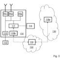
- Figure 3 illustrates a distributed implementation, also referred to as a cloud implementation, of the apparatus 700 according to an example scenario.
- the radio traffic scheduler 119 in BB may in this example scenario be located as a function in the cloud 130.
- the difference compared with the implementation shown in Figure 2 is that the PRCF 118 is split into two entities: a client 118b and a server 118a.
- the PRCF server 118a may be responsible for determining, e.g. by computation, which PA or which several PAs that are to be connected to the PV power 114. If the energy de-multiplexer 117 is utilized as is illustrated in Figure 3 , the PRCF server 118a determines which actuator in the energy de-multiplexer 117 to actuate. This information is then relayed to the PRCF client 118b via for example the data traffic scheduler 119. Based on the information received the PRCF client 118b may control which PA is connected to the PV power 114, e.g. by actuating the controls in the energy de-multiplexer 117. It may also report to the PRCF server 118a the current PV power 114 production, e.g.
- the PRCF server 118a may e.g. be running in the cloud 130, e.g. on a server in a data center and the PRCF client 118b may e.g. be located in the radio unit 110.
- radio units 110 may be controlled by one PRCF server 118a and client 118b configuration. The cloud implementation will be described further below.
- Example embodiments of a method for controlling allotment of power input between at least two PAs of the radio unit 110 for data communication will now be described with reference to a flowchart depicted in Figure 4 .
- the radio unit 110 operate in the wireless communication network 100 and has access to DC power 112 and PV power 114.
- the actions below may be performed by any one or more out of the radio unit 110, a separate non-virtualized node or a separate node hosted in a public or private cloud 130, such as e.g. by a server, a Distributed Node DN or functionality in the cloud 130.
- the method comprises the following actions, which actions may be performed in any suitable order. Dashed boxes represent optional method steps.
- the radio unit 110 Since the radio unit 110 has access to the PV power 114 in addition to the DC power 112 the radio unit 110 may use PV power 114 as soon as it is possible. Thus, since PV power 114 is a renewable energy source, a more environmental friendly operation is achieved. Furthermore, the noise generation may also be lower as will be explained further below. However, in order to achieve this, the amount of power transmitted by the PAs of the radio unit 110 may be determined. The amount of power to be transmitted out from each respective PA out of the at least two PAs is thus established.
- the amount of power transmitted out of a PA is correlated to the amount of power consumed by this PA and is thus a measure of the amount of power the PA need in order to operate.
- the amount of power consumed by the PA may depend on the traffic allocated to the PA.
- the amount of power transmitted out of each respective PA may e.g. be established based on information related to the amount of power consumed by the respective PA, the amount of traffic allocated to the PA etc.
- the information related to the amount of power consumed by the respective PA may e.g. be determined by the radio traffic scheduler 119 related to the radio unit 110.
- the amount of power to be transmitted out from each PA out of the at least two PAs may be established by a respective previous prediction of the amount of power to be transmitted out from each respective PA out of the at least two PAs.
- the respective prediction is based on the amount of historical traffic generated.
- the amount of power to be transmitted out from each respective PA out of the at least two PAs may e.g. be established based on machine learning.
- the PV source is solar energy, which is a very intermittent renewable energy source the amount of power may vary considerably at short, medium and long timescales.
- the information related to the amount of PV power 114 available may relate to any one or more out of current power measurements of the PV power 114, historical power measurements of the PV power 114, the current weather surrounding the radio unit 110 and the historical weather surrounding the radio unit 110.
- the current or historical weather surrounding the radio unit 110 may for instance be the amount of sunlight irradiation, the temperature, the time of day etc.
- the amount of PV power 114 available may in some embodiments be obtained by a previous prediction of the amount of PV power 114 available, wherein the previous prediction is based on one or more out of PV power 114 production, light irradiation, temperature, time of day, the altitude at which the PV power source is located and the efficiency of the PV power source.
- the previous prediction may furthermore be based on the date, the atmospheric humidity, precipitation etc.
- the information related to the amount of PV power 114 available may be obtained based on machine learning.
- At least one first PA out of the at least two PAs is established.
- the at least one first PA will be transmitting the most amount of power out of the at least two PAs.
- the method further comprises controlling the allotment of power input of DC power 112 and PV power 114 between the at least two PAs based on the established amount of power to be transmitted out from each respective PA out of the at least two PAs, and the obtained information related to the amount of PV power 114 available.
- the first threshold value may e.g. be the amount of power used by the PA which transmits the most amount of power.
- the first threshold value may also be a fixed value, e.g. a value of 20W, 40W, 60W or 80W or any other value defined as suitable.
- the PV power 114 may be distributed to the PA transmitting the second most amount of power and so forth.
- all the PV power 114 may be still be allotted to the PA which transmits the most amount of power and the extra power needed to feed that PA may be received from the DC power 112.
- the DC power 112 may in that case be adjusted so that the right amount of power reaches the PA.
- the available PV power may fluctuate continuously as the light intensity which is used to produce the PV power changes over time. It is therefore advantageous to continuously adapt the distribution of the power to the PAs in order to achieve a high efficiency.
- the controlling of allotment of power input between the at least two PAs is thus updated by: re-establishing the amount of power to be transmitted out from each respective PA out of the at least two PAs, obtaining updated information related to the amount of PV power available, and controlling the allotment of power input of DC power and PV power between the at least two PAs based on:
- the updating may be performed at a time interval which e.g. is related to a Transmission Time Interval (TTI) of the data communication.
- TTI Transmission Time Interval
- a TTI is the duration of a transmission on the radio link and depends on the size of the data blocks used for the communication.
- One TTI may e.g. correspond to 1 ms for LTE and lower than 70us for NR.
- the update interval may e.g. range from a very fast update process where the control is updated every TTI to slower update intervals of several TTIs.
- the slower process may range from 2 TTls to several seconds.
- Using a fast update process will result in a high accuracy since changes in PV power production and power consumption of the PAs may be followed very closely. It is however hard to virtualize such a fast update algorithm since the software executing the algorithm needs to be in close vicinity to the physical hardware, such as e.g. the radio unit 110.
- the software may in this case e.g. be placed in a datacentre connected to the radio unit 110.
- the updating time interval may be determined based on machine learning.
- Machine learning may for instance be used to plan in intervals greater than 1 TTI, by e.g. predicting environmental conditions and the amount of future traffic generated based on historical data.
- the machine learning models used may e.g. be based on Deep Neural Networks (DNN).
- the controlling of allotment of power input between the at least two PAs may furthermore be updated by further comprising re-establishing at least one second PA out of the at least two PAs, which second PA will be transmitting the most amount of power out of the at least two PAs.
- the PV power available exceeds a first threshold value, all of the PV power is allotted to the second PA.
- the second PA may be the same as the first PA, i.e. in that case the first PA is still the PA which will be transmitting the most amount power.
- the second PA may be the same as the first PA, i.e. in that case the first PA is still the PA which will be transmitting the most amount power.
- the PV power 114 source may be connected to the specific PA via the energy de-multiplexer 117.
- the PV power 114 may be distributed amongst several PAs or all of the power may be allotted to the highest power-consuming PA.
- the energy de-multiplexer 117 may be controlled by a PRCF 118.
- the PRCF 118 may receive data concerning the power to be transmitted from each PA from a radio traffic scheduler 119. The PRCF 118 may use this data to control the energy de-multiplexer 117 to supply PV power 114 to the PA consuming the most amount of power.
- the radio traffic scheduler 119 may be the component which allocates the radio traffic towards each PA. Each traffic allocation corresponds to a certain power level. The corresponding power levels may be sent from radio traffic scheduler 119 to the PRCF 118. In addition, the PA having the highest allocated power level may also be indicated by the information sent from the radio traffic scheduler 119. This information may be known to the radio traffic scheduler 119 one TTI in advance. Thereby a control mechanism for controlling e.g. the energy de-multiplexer 117 to distribute the PV power 114 between the PAs is created. The control mechanism may thus e.g. feed all of the PV power 114 to the PA consuming the most amount of power. Through this control method, the energy needed from DC power 112 obtained from the grid or other sources than the PV source is reduced.
- the provided method for controlling allotment of power input between at least two PAs of a radio unit 110 for data communication will now be further explained through example scenarios.
- the PRCF 118 schedules PV-supplied power based on current power consumption, also referred to as provisioning characteristics, and historical measurements.
- the PRCF 118 may be a logical component. As has been described and will be described in more detail below, it may physically reside within the radio unit 110, on a digital ASIC of the radio unit 110, as a cloud 130 function, e.g. in a server within a data center etc. In the following general description the PRCF 118 will be described as a single entity with the understanding that the same functions could e.g. be performed by a PRCF 118 which is split into a PRCF client 118b and a PRCF server 118a as was described above.
- the PRCF 118 may thus be capable of receiving a number of different inputs, e.g. in the form of data related to any one or more out of:
- Possible outputs from the PRCF 118 may e.g. be any one or more out of:
- the radio traffic scheduler 119 may provide information regarding the power allocation of each PA one TTI in advance.
- the power allocation of each PA is the power each PA will transmit in the next TTI.
- the power allocation may e.g. be expressed in percentage of traffic, or in Watts.
- the radio traffic scheduler 119 may determine the value in average and/or peak Watts given the value in percentage of traffic, since the amount of traffic is directly proportional to the amount of power required to channel this traffic.
- An advantage is that embodiments provided herein may reduce the noise stemming from the PAs, since PV power have lower noise than DC/DC.
- an advantage is that a gain in the noise difference levels on the PA voltage is achieved.
- a PV source e.g. a solar cell panel, has no active components compared to DC/DC where switching arrangements produce noise. This noise needs to be filtered on the PA bus voltage. This means that the Digital Pre-Distortion (DPD) does not need to compensate for noise from PV power as compared to power from DC/DC in such high degree.
- DPD Digital Pre-Distortion
- a yet further advantage is that the method and apparatus 700 may adapt to variable weather condition patterns by adjusting the DC/DC output voltage via a output voltage adjustment interface (V adj ), to the PAs. This may be done in order to increase the power taken from the PV. When sunlight is diffuse the power may e.g. be reduced from the PV source.
- V adj output voltage adjustment interface
- a further advantage is that machine learning algorithms may be used to plan in intervals of longer time, by predicting environmental conditions and the amount of future traffic generated based on historical data, making the apparatus 700 and method robust and adaptable.
- control may be updated at a time interval which is related to a TTI of the data communication.
- a fast update which occurs once every TTI
- a slower update which occurs at an interval equal to or greater than two TTIs.
- the updating of the controlling of the allotment is performed every TTI.
- the controls connecting the PV power 114 to the PAs are actuated in every TTI. This may correspond to the timings of the radio traffic scheduler 119.
- the PRCF 118 also need to run every TTI, since the PRCF 118 according to this scenario schedules the PV power 114.
- one advantage of the fast update is the high accuracy achieved.
- a possible draw-back may be that the software executing the PRCF 118 needs to be physically very close to the radio unit 110 so that the PV controls may be actuated within a TTI.
- the fast update will yield fine-grained results and relies on currently results of power and weather.
- the PRCF 118 may establish the power to be transmitted out from each PA.
- the PRCF 118 obtains the current PV power 114 available. This may e.g. be obtained through measured current and voltage values at the PV source which is transmitted to the PRCF 118.
- the PRCF 118 Based on the established power to be transmitted out from each PA and the current PV power 114 available the PRCF 118 performs a power allotment decision, i.e. how to distribute the PV power 114 and the DC power 112 to the PAs.
- the PA having the highest traffic allocation in the next TTI may be identified as PA max .
- the PRCF 118 may check if the power to be transmitted out from the PA identified as PA max is greater than the current PV power 114 available. In that case the adjustable voltage distribution V adjust of the DC power 112 may be used. The PRCF 118 may then control the output voltage from the DC/DC unit 113 accordingly such that the right amount of power is received for each PA from the DC/DC unit 13 and the PV power 114, thus If PA max > PV power available use adjustable voltage for DC power 112.
- the PRCF 118 may then control the energy de-multiplexer 117based on the allotment decision by opening, action 506, or closing, action 507, the appropriate PV controls.
- the decision algorithm to actuate the power controls may more formally be as follows:
- one of the PAs may be chosen at random to receive the PV power 114.
- the updating of the controlling of the allotment is performed at every multiple of TTIs, e.g. every second TTI or once every 10 th TTI, etc.
- the controls connecting the PV power 114 to the PAs are actuated after multiple TTIs have elapsed.
- the time elapsed may range from 2 TTls to many seconds.
- the updating function may not need to be as close to the radio unit 110 as in the fast updating scenario.
- the software function may in this case be executed in a server in a datacenter and may e.g. be connected to the radio unit 110 using an optical fiber front haul, e.g. the Common Public Radio Interface, CPRI. This may e.g. be the case for Cloud RAN type deployments.
- CPRI Common Public Radio Interface
- the slow update scenario is delay tolerant and relies on historical data values.
- the amount of power to be transmitted out from each respective PA during the time interval need to be established. Furthermore, information related to the amount of PV power available during the time interval need also be obtained. Since the actual values are not available they need to be obtained such as be predicted. For purposes of illustration it is assumed here that the prediction is performed for k TTIs. Instead of direct comparisons of power values as for the fast update scenario, models of values are used in the slow update scenario. The models predict what the allocated values to the PAs as well as the supplied PV power 114 will be for the next k TTIs. The allocated values may be allocated by a power allocator such as a radio traffic scheduler 119 and the models then predict how much power the allocator will allocate a given PA.
- a power allocator such as a radio traffic scheduler 119
- the models may be built based on historical data. If the semantics of the data is known, e.g. that the data is characterized as power measurements, the data may be considered as labeled. Models for labeled data may therefore be used, e.g. different types of regression techniques such as DNN may be used.
- variables such as PV power production, irradiation and temperature are correlated to the power production.
- Other examples of variables influencing the power production may be the time of day, the time of year, the altitude at which the PV power source is located, the date, the atmospheric humidity, precipitation etc.
- these variables may be used as input for the models, e.g. as inputs to the DNN.
- These variables may herein also be referred to as independent variables.
- Actual values of the available PV power may be used in conjunction with the independent variables in order to train the model.
- the actual values may e.g. be the actual power produced as measured by the current and voltage at the PV source.
- the power production may then be predicted based on current values of the independent variables.
- a similar correlation may be made for power allocation to the PAs, or for the power allocation the scheduler will allocate to the PAs.
- the allocation may be based on the amount of traffic generated.
- the amount of traffic generated is correlated to the number of active users.
- the independent variables for the power allocation prediction may be the traffic generated or the number of active users.
- PV pwr f(P iv1 , P iv2 , ...P ivx ), where P iv1 , P iv2 , ...P ivx are independent variables such as the ones mentioned above with regards to predicting the PV power production.
- the function may predict the allocated power PA kpwr to every PA k from the radio scheduler for the next k TTIs.
- PA kpwr y(S iv1 , S iv2 , ... S ivx ), where S iv1 , S iv2 , ... S ivx are independent variables such as the ones mentioned above with regards to predicting the power allocation to the PAs.
- PV control1 , PV control2 , ..., PV r be the current state of control 1, 2, ...r.
- the state may be OPEN or CLOSED.
- OPEN the switch is open, i.e. no current may flow through and thus no PV power will be distributed to the corresponding PA.
- CLOSED the switch is closed, i.e. current may flow through and thus power will be distributed to the corresponding PA.
- current state is herein meant what the outcome was of the decision in the previous TTI.
- PV ctrl max and “PV ctrl rest” in Figure 6 correspond to the same features as described above in conjunction with Figure 5 .
- Actions 601-604 are performed in order to train the models described above. Those steps are therefore performed continuously and simultaneously to actions 605-611. These latter steps are performed in order to control the power allotment to the PAs.
- the PRCF 118 obtains data related to the PV power 114 available, e.g. in the form of the actual power produced obtained through direct power measurements, e.g. the current and voltage of the PV source, as well as indirect data of independent variables such as light irradiation, temperature, time of day etc. This data may be collected at the PV source and transmitted to the PRCF 118.
- the model describing the production of PV power may in step 602 be trained by the PRCF 118.
- data regarding the PA power allocation is collected.
- the data may be collected by the radio traffic controller 119 and be transmitted to the PRCF 118.
- the data collected may comprise the actual power allocated for each PA as well as independent variables such as e.g. the number of active users, the geographic location, the time of day etc.
- the model describing the PA power allocation may in step 604 be trained by the PRCF 118.
- the PRCF 118 collects current independent data for the PV power 114.
- the independent data may e.g. be light irradiation, temperature, time of day etc.
- the data may e.g. be collected at the PV source and be transmitted from the source site to the PRCF 118.
- the PRCF 118 collects current independent data for the PA power allocation, such as e.g. number of active users, the time of day, the geographical location etc.
- the data may be collected by the radio traffic scheduler 119 and transmitted to the PRCF 118.
- the PRCF 118 may predict the power allocated PA1alloc, PA2alloc, ... PANalloc to each of the PAs PA1, PA2 ... PAN for k TTIs in the future by using the trained model for PA power allocation. Similarly the PRCF 118 may also predict the PV power 114 available for k TTIs using the trained model for PV power production.
- the PRCF 118 may decide a power allotment.
- the PA having the highest traffic allocation in the next k TTIs may be identified as PA max . If the PA max is identified the PRCF 118 may check if the power to be transmitted out from the PA identified as PA max is greater than the current PV power 114 available. In that case the adjustable voltage distribution V adjust of the DC power 112 may be used. The PRCF 118 may then control the DC/DC unit 113 output voltage accordingly such that the right amount of power for each respective PA is received from the DC/DC unit 113 and the PV power 114, thus If PA max > PV power 114 available use adjustable voltage for DC power 112.
- the PRCF 118 may then control the energy de-multiplexer 117 based on the allotment decision by opening, action 610, or closing, action 611, the appropriate PV controls.
- the decision algorithm to actuate the power controls may more formally be as follows:
- the apparatus 700 may comprise the arrangement depicted in Figures 7a and 7b .
- the radio unit 110 has access to DC power and PV power.
- the apparatus 700 may comprise an input and output interface 705 configured to communicate with network nodes.
- the input and output interface 705 may comprise a wireless receiver (not shown) and a wireless transmitter (not shown).
- the apparatus 700 is configured to establish the amount of power to be transmitted out from each respective PA out of the at least two PAs, e.g. by means of an establishing unit 710 in the apparatus 700.
- the apparatus 700 may further be configured to, e.g. by means of the establishing unit 710 in the apparatus 700, establish at least one first PA out of the at least two PAs, which at least one first PA will be transmitting the most amount of power out of the at least two PAs, and when the PV power available exceeds a first threshold value, allot all of the PV power to the at least one first PA.
- the amount of power to be transmitted out from each respective PA out of the at least two PAs may be adapted to be established based on machine learning.
- the apparatus 700 is further configured to obtain information related to the amount of PV power available, e.g. by means of an obtaining unit 720 in the apparatus 700.
- the information related to the amount of PV power available may be adapted to be related to any one or more out of current power measurements of the PV power, historical power measurements of the PV power, the current weather surrounding the radio unit 110, and the historic weather surrounding the radio unit 110 to description.
- the information related to the amount of PV power 114 available may be adapted to be obtained based on machine learning.
- the apparatus 700 is further configured to, e.g. by means of a controlling unit 730 in the apparatus 700, control the allotment of power input of DC power and PV power between the at least two PAs based on:
- the apparatus 700 may further be configured to, e.g. by means of an updating unit 740 in the apparatus 700, update the control of allotment of power input between the at least two PAs by re-establishing the amount of power to be transmitted out from each respective PA out of the at least two PAs, obtaining updated information related to the amount of PV power available, and controlling the allotment of power input of DC power and PV power between the at least two PAs based on:
- the apparatus 700 may be configured to, e.g. by means of the updating unit 740 in the apparatus 700, perform the update at a time interval which is adapted to be related to a Transmission Time Interval, TTI, of the data communication.
- the updating time interval may be adapted to be determined based on machine learning.
- the apparatus 700 may be further configured to, e.g. by means of the updating unit 740 in the apparatus 700, update the control of allotment of power input between the at least two PAs by being configured to re-establish at least one second PA, which second PA will be transmitting the most amount of power out of the at least two PAs, and when the PV power available exceeds a first threshold value, allot all of the PV power to the second PA.
- the apparatus 700 may be further configured to, e.g. by means of the establishing unit 710 in the apparatus 700, establish the amount of power to be transmitted out from each PA out of the at least two PAs by a respective previous prediction of the amount of power to be transmitted out from each respective PA out of the at least two PAs, wherein the respective prediction is based on the amount of historical traffic generated.
- the apparatus 700 may be further configured to, e.g. by means of the obtaining unit 740 in the apparatus 700, obtain the amount of PV power available by a previous prediction of the amount of PV power available, wherein the previous prediction is adapted to be based on one or more out of PV power production, light irradiation, temperature and time of day.
- the apparatus 700 may be any one or more out of the radio unit 110, a separate non-virtualized node or a separate node hosted in a public or private cloud such as e.g. the cloud 130, e.g. a server in a cloud 130.
- a public or private cloud such as e.g. the cloud 130, e.g. a server in a cloud 130.
- the embodiments herein may be implemented through a respective processor or one or more processors, such as a processor 770 of a processing circuitry in the apparatus 700 depicted in Figure 7a together with respective computer program code for performing the functions and actions of the embodiments herein.
- the program code mentioned above may also be provided as a computer program product, for instance in the form of a data carrier carrying computer program code for performing the embodiments herein when being loaded into apparatus 700.
- a data carrier may be in the form of a CD ROM disc. It is however feasible with other data carriers such as a memory stick.
- the computer program code may furthermore be provided as pure program code on a server and downloaded to the apparatus 700.
- the apparatus 700 may further comprise a memory 780 comprising one or more memory units.
- the memory 780 comprises instructions executable by the processor in the apparatus 700.
- the memory 780 is arranged to be used to store e.g. data, configurations, and applications to perform the methods herein when being executed in the apparatus 700.
- a computer program 790 comprises instructions, which when executed by the at least one processor 770 cause the at least one processor of the apparatus 700 to perform the actions above.
- a carrier 795 comprises the respective computer program, wherein the carrier 795 is one of an electronic signal, an optical signal, an electromagnetic signal, a magnetic signal, an electric signal, a radio signal, a microwave signal, or a computer-readable storage medium.
- the energy de-multiplexer 117 may activate PV control pin number 2 in order to connect the PV power 114 with the PA PA2, and thereby reducing the energy requirements of the DC/DC unit 113.
- the PV power 114 source may preferably match the PA voltage, e.g. +35VDC, to be able to support the same voltage range as the PA.
- the power from the PV may also be matched. For instance, assuming that the radio total consumption is 600W, the PV power source may support the radio unit 110 with 300W peak power.
- the PRCF 118 may comprise the PRCF server 118a and the PRCF client 118b.
- the PRCF server 118a may be responsible for determining, e.g. by computation, which PA or which several PAs that are to be connected to the PV power 114. If a de-multiplexer 117 is utilized as is illustrated in Figure 3 , the PRCF server 118a determines which actuator in the demux 117 to actuate.
- the PRCF server 118a may be a pure software function that may be running in a cloud 130, e.g. on a server in a datacenter e.g. using Infrastructure as a Service, laaS, or Platform as a Service, PaaS, software.
- the PRCF 118a could be docker containers, or set of containers, running on top of OpenStack, Kubernetes, Cloudify or any similar platform.
- the PRCF 118a may accept the scheduled traffic or power to be transmitted by the PAs and the PV power 114 available, e.g.
- the PRCF server 118a decides on an actuation plan using these two models, i.e. e.g. to which PA the PV power 114 should be distributed and for how long a time. Then it may submit the actuation plan to the PRCF client 118b.
- the PRCF client 118b may thus receive the actuation plan from PRCF server 118a, e.g. through the radio traffic controller 119. Based on the information received the PRCF client 118b may control which PA is connected to the PV power 114, e.g. by actuating the controls in the demux 117. It may also report to the PRCF server 118a the current PV power 114 production, e.g. by transmitting data obtained by measuring the current voltage and current. If the PRCF server 118a needs additional information to e.g. train a PV production model using machine learning, the PRCF client 118b may collect additional assorted information such as irradiation and temperature and transmit to the PRCF server 118a.
- the radio traffic controller 119 may relay information between PRCF Client 118b and the PRCF server 118a. In addition, the radio traffic controller 119 may compute its own traffic allocation estimates and provide the PRCF server 118a with that information. This information may be used by the PRCF server 118a to e.g. train a power allocation model using machine learning.
- the distributed cloud implementation scenario will be most beneficial when using machine learning, i.e. for updating time intervals where the predictions are performed for k TTIs in advance, where k >> 1.
- a communication system includes a telecommunication network 3210 such as the wireless communications network 100, e.g. an loT network, or a WLAN, such as a 3GPP-type cellular network, which comprises an access network 3211, such as a radio access network, and a core network 3214.
- the access network 3211 comprises a plurality of base stations 3212a, 3212b, 3212c, such as e.g. the radio units 110, 120, access nodes, AP STAs NBs, eNBs, gNBs or other types of wireless access points, each defining a corresponding coverage area 3213a, 3213b, 3213c.
- Each base station 3212a, 3212b, 3212c is connectable to the core network 3214 over a wired or wireless connection 3215.
- a first user equipment (UE) e.g. the radio unit 110, 120, such as a Non-AP STA 3291 located in coverage area 3213c is configured to wirelessly connect to, or be paged by, the corresponding base station 3212c.
- a second UE 3292 e.g. the wireless device 122 such as a Non-AP STA in coverage area 3213a is wirelessly connectable to the corresponding base station 3212a. While a plurality of UEs 3291, 3292 are illustrated in this example, the disclosed embodiments are equally applicable to a situation where a sole UE is in the coverage area or where a sole UE is connecting to the corresponding base station 3212.
- the telecommunication network 3210 is itself connected to a host computer 3230, which may be embodied in the hardware and/or software of a standalone server, a cloud-implemented server, a distributed server or as processing resources in a server farm.
- the host computer 3230 may be under the ownership or control of a service provider, or may be operated by the service provider or on behalf of the service provider.
- the connections 3221, 3222 between the telecommunication network 3210 and the host computer 3230 may extend directly from the core network 3214 to the host computer 3230 or may go via an optional intermediate network 3220.
- the intermediate network 3220 may be one of, or a combination of more than one of, a public, private or hosted network; the intermediate network 3220, if any, may be a backbone network or the Internet; in particular, the intermediate network 3220 may comprise two or more sub-networks (not shown).
- the communication system of Figure 8 as a whole enables connectivity between one of the connected UEs 3291, 3292 and the host computer 3230.
- the connectivity may be described as an over-the-top (OTT) connection 3250.
- the host computer 3230 and the connected UEs 3291, 3292 are configured to communicate data and/or signaling via the OTT connection 3250, using the access network 3211, the core network 3214, any intermediate network 3220 and possible further infrastructure (not shown) as intermediaries.
- the OTT connection 3250 may be transparent in the sense that the participating communication devices through which the OTT connection 3250 passes are unaware of routing of uplink and downlink communications.
- a base station 3212 may not or need not be informed about the past routing of an incoming downlink communication with data originating from a host computer 3230 to be forwarded (e.g., handed over) to a connected UE 3291. Similarly, the base station 3212 need not be aware of the future routing of an outgoing uplink communication originating from the UE 3291 towards the host computer 3230.
- a host computer 3310 comprises hardware 3315 including a communication interface 3316 configured to set up and maintain a wired or wireless connection with an interface of a different communication device of the communication system 3300.
- the host computer 3310 further comprises processing circuitry 3318, which may have storage and/or processing capabilities.
- the processing circuitry 3318 may comprise one or more programmable processors, application-specific integrated circuits, field programmable gate arrays or combinations of these (not shown) adapted to execute instructions.
- the host computer 3310 further comprises software 3311, which is stored in or accessible by the host computer 3310 and executable by the processing circuitry 3318.
- the software 3311 includes a host application 3312.
- the host application 3312 may be operable to provide a service to a remote user, such as a UE 3330 connecting via an OTT connection 3350 terminating at the UE 3330 and the host computer 3310. In providing the service to the remote user, the host application 3312 may provide user data which is transmitted using the OTT connection 3350.
- the communication system 3300 further includes a base station 3320 provided in a telecommunication system and comprising hardware 3325 enabling it to communicate with the host computer 3310 and with the UE 3330.
- the hardware 3325 may include a communication interface 3326 for setting up and maintaining a wired or wireless connection with an interface of a different communication device of the communication system 3300, as well as a radio interface 3327 for setting up and maintaining at least a wireless connection 3370 with a UE 3330 located in a coverage area (not shown) served by the base station 3320.
- the communication interface 3326 may be configured to facilitate a connection 3360 to the host computer 3310.
- the connection 3360 may be direct or it may pass through a core network (not shown in Figure 9 ) of the telecommunication system and/or through one or more intermediate networks outside the telecommunication system.
- the hardware 3325 of the base station 3320 further includes processing circuitry 3328, which may comprise one or more programmable processors, application-specific integrated circuits, field programmable gate arrays or combinations of these (not shown) adapted to execute instructions.
- the base station 3320 further has software 3321 stored internally or accessible via an external connection.
- the communication system 3300 further includes the UE 3330 already referred to. Its hardware 3335 may include a radio interface 3337 configured to set up and maintain a wireless connection 3370 with a base station serving a coverage area in which the UE 3330 is currently located.
- the hardware 3335 of the UE 3330 further includes processing circuitry 3338, which may comprise one or more programmable processors, application-specific integrated circuits, field programmable gate arrays or combinations of these (not shown) adapted to execute instructions.
- the UE 3330 further comprises software 3331, which is stored in or accessible by the UE 3330 and executable by the processing circuitry 3338.
- the software 3331 includes a client application 3332.
- the client application 3332 may be operable to provide a service to a human or non-human user via the UE 3330, with the support of the host computer 3310.
- an executing host application 3312 may communicate with the executing client application 3332 via the OTT connection 3350 terminating at the UE 3330 and the host computer 3310.
- the client application 3332 may receive request data from the host application 3312 and provide user data in response to the request data.
- the OTT connection 3350 may transfer both the request data and the user data.
- the client application 3332 may interact with the user to generate the user data that it provides.
- the host computer 3310, base station 3320 and UE 3330 illustrated in Figure 9 may be identical to the host computer 3230, one of the base stations 3212a, 3212b, 3212c and one of the UEs 3291, 3292 of Figure 10 , respectively.
- the inner workings of these entities may be as shown in Figure 9 and independently, the surrounding network topology may be that of Figure 8 .
- the OTT connection 3350 has been drawn abstractly to illustrate the communication between the host computer 3310 and the use equipment 3330 via the base station 3320, without explicit reference to any intermediary devices and the precise routing of messages via these devices.
- Network infrastructure may determine the routing, which it may be configured to hide from the UE 3330 or from the service provider operating the host computer 3310, or both. While the OTT connection 3350 is active, the network infrastructure may further take decisions by which it dynamically changes the routing (e.g., on the basis of load balancing consideration or reconfiguration of the network).
- the wireless connection 3370 between the UE 3330 and the base station 3320 is in accordance with the teachings of the embodiments described throughout this disclosure.
- One or more of the various embodiments improve the performance of OTT services provided to the UE 3330 using the OTT connection 3350, in which the wireless connection 3370 forms the last segment. More precisely, the teachings of these embodiments may improve the applicable RAN effect: data rate, latency, power consumption, and thereby provide benefits such as corresponding effect on the OTT service: e.g. reduced user waiting time, relaxed restriction on file size, better responsiveness, extended battery lifetime.
- a measurement procedure may be provided for the purpose of monitoring data rate, latency and other factors on which the one or more embodiments improve.
- the measurement procedure and/or the network functionality for reconfiguring the OTT connection 3350 may be implemented in the software 3311 of the host computer 3310 or in the software 3331 of the UE 3330, or both.
- sensors (not shown) may be deployed in or in association with communication devices through which the OTT connection 3350 passes; the sensors may participate in the measurement procedure by supplying values of the monitored quantities exemplified above, or supplying values of other physical quantities from which software 3311, 3331 may compute or estimate the monitored quantities.
- the reconfiguring of the OTT connection 3350 may include message format, retransmission settings, preferred routing etc.; the reconfiguring need not affect the base station 3320, and it may be unknown or imperceptible to the base station 3320. Such procedures and functionalities may be known and practiced in the art.
- measurements may involve proprietary UE signaling facilitating the host computer's 3310 measurements of throughput, propagation times, latency and the like.
- the measurements may be implemented in that the software 3311, 3331 causes messages to be transmitted, in particular empty or 'dummy' messages, using the OTT connection 3350 while it monitors propagation times, errors etc.
- FIG 10 is a flowchart illustrating a method implemented in a communication system, in accordance with one embodiment.
- the communication system includes a host computer, a base station such as e.g. the radio unit 110 (which may be a base station or a UE), and a UE such as e.g. the radio unit 110 (which may be a base station or a UE), which may be those described with reference to Figure 8 and Figure 9 .
- a first action 3410 of the method the host computer provides user data.
- the host computer provides the user data by executing a host application.
- the host computer initiates a transmission carrying the user data to the UE.
- the base station transmits to the UE the user data which was carried in the transmission that the host computer initiated, in accordance with the teachings of the embodiments described throughout this disclosure.
- the UE executes a client application associated with the host application executed by the host computer.
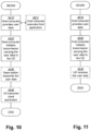
- FIG 11 is a flowchart illustrating a method implemented in a communication system, in accordance with one embodiment.
- the communication system includes a host computer, a base station such as a AP STA, and a UE such as a Non-AP STA which may be those described with reference to Figure 8 and Figure 9 .
- a first action 3510 of the method the host computer provides user data.
- the host computer provides the user data by executing a host application.
- the host computer initiates a transmission carrying the user data to the UE. The transmission may pass via the base station, in accordance with the teachings of the embodiments described throughout this disclosure.
- the UE receives the user data carried in the transmission.
- FIG 12 is a flowchart illustrating a method implemented in a communication system, in accordance with one embodiment.
- the communication system includes a host computer, a base station such as a AP STA, and a UE such as a Non-AP STA which may be those described with reference to Figure 8 and Figure 9 .
- a first action 3610 of the method the UE receives input data provided by the host computer.
- the UE provides user data.
- the UE provides the user data by executing a client application.
- the UE executes a client application which provides the user data in reaction to the received input data provided by the host computer.
- the executed client application may further consider user input received from the user.
- the UE initiates, in an optional third subaction 3630, transmission of the user data to the host computer.
- the host computer receives the user data transmitted from the UE, in accordance with the teachings of the embodiments described throughout this disclosure.
- FIG. 13 is a flowchart illustrating a method implemented in a communication system, in accordance with one embodiment.
- the communication system includes a host computer, a base station such as a AP STA, and a UE such as a Non-AP STA which may be those described with reference to Figure 8 and Figure 9 .
- a first action 3710 of the method in accordance with the teachings of the embodiments described throughout this disclosure, the base station receives user data from the UE.
- the base station initiates transmission of the received user data to the host computer.
- the host computer receives the user data carried in the transmission initiated by the base station.
Landscapes
- Engineering & Computer Science (AREA)
- Power Engineering (AREA)
- Physics & Mathematics (AREA)
- Condensed Matter Physics & Semiconductors (AREA)
- Electromagnetism (AREA)
- General Physics & Mathematics (AREA)
- Computer Hardware Design (AREA)
- Microelectronics & Electronic Packaging (AREA)
- Remote Monitoring And Control Of Power-Distribution Networks (AREA)
- Transmitters (AREA)
Claims (18)
- Procédé de commande d'une attribution d'entrée de puissance entre au moins deux amplificateurs de puissance, PA, d'une unité radio (110) pour une communication de données dans un réseau de communications sans fil (100), laquelle unité radio (110) a accès à une puissance en courant continu, CC, (112) et à une puissance photovoltaïque, PV, (114), le procédé comprenant :l'établissement (201) de la quantité de puissance devant être transmise à partir de chaque PA respectif parmi les au moins deux PA,l'obtention (202) d'informations liées à la quantité de puissance PV (114) disponible, la commande (204) de l'attribution d'entrée de puissance de puissance CC (112) et de puissance PV(114) entre les au moins deux PA sur la base de :- la quantité établie de puissance devant être transmise à partir de chaque PA respectif parmi les au moins deux PA, et- des informations obtenues liées à la quantité de puissance PV (114) disponible.
- Procédé selon la revendication 1, comprenant en outre :l'établissement (203) d'au moins un premier PA parmi les au moins deux PA, lequel au moins un premier PA transmettra la plus grande quantité de puissance parmi les au moins deux PA, etlorsque la puissance PV (114) disponible dépasse une première valeur seuil, l'attribution de toute la puissance PV au au moins un premier PA.
- Procédé selon l'une quelconque des revendications 1-2, dans lequel les informations liées à la quantité de puissance PV (114) disponible se rapportent à une quelconque ou plusieurs parmi :des mesures de puissance courantes de la puissance PV (114),des mesures de puissance historiques de la puissance PV (114),les conditions météorologiques courantes entourant l'unité radio (110), etles conditions météorologiques historiques entourant l'unité radio (110).
- Procédé selon l'une quelconque des revendications 1-3, comprenant en outre :
la mise à jour (205) de la commande d'attribution d'entrée de puissance entre les au moins deux PA en :établissant à nouveau la quantité de puissance devant être transmise à partir de chaque PA respectif parmi les au moins deux PA,obtenant des informations mises à jour liées à la quantité de puissance PV (114) disponible, commandant l'attribution d'entrée de puissance de puissance CC (112) et de puissance PV (114) entre les au moins deux PA sur la base de :- la quantité établie à nouveau de puissance devant être transmise à partir de chaque PA respectif parmi les au moins deux PA, et- des informations mises à jour obtenues liées à la quantité de puissance PV (114) disponible. - Procédé selon l'une quelconque des revendications 1-4, dans lequel les informations liées à la quantité de puissance PV (114) disponible sont obtenues sur la base d'un apprentissage automatique et/ou la quantité de puissance devant être transmise à partir de chaque PA respectif parmi les au moins deux PA est établie sur la base d'un apprentissage automatique.
- Procédé selon l'une quelconque des revendications 4-5 :
dans lequel la mise à jour (205) de la commande d'attribution d'entrée de puissance entre les au moins deux PA en comprenant en outre :le fait d'établir à nouveau au moins un second PA parmi les au moins deux PA, lequel second PA transmettra la plus grande quantité de puissance parmi les au moins deux PA, etlorsque la puissance PV (114) disponible dépasse une première valeur seuil, l'attribution de toute la puissance PV (114) au second PA. - Procédé selon l'une quelconque des revendications 1-6, dans lequel la quantité de puissance devant être transmise à partir de chaque PA parmi les au moins deux PA est établie par une prédiction antérieure respective de la quantité de puissance devant être transmise à partir de chaque PA respectif parmi les au moins deux PA, dans lequel la prédiction respective est basée sur la quantité de trafic historique générée.
- Procédé selon l'une quelconque des revendications 1-7, dans lequel la quantité de puissance PV (114) disponible est obtenue par une prédiction antérieure de la quantité de puissance PV (114) disponible, dans lequel la prédiction antérieure est basée sur une ou plusieurs parmi :la production de puissance PV (114),l'exposition à la lumière,la température,l'heure de la journée,l'altitude à laquelle la source de puissance PV est située, etle rendement de la source de puissance PV.
- Procédé selon l'une quelconque des revendications 1-8, dans lequel les actions dans le procédé sont réalisées par un quelconque ou plusieurs parmi :
l'unité radio (110), un noeud non virtualisé distinct ou un noeud distinct hébergé dans un cloud public ou privé (130). - Appareil (700) configuré pour commander une attribution d'entrée de puissance entre au moins deux amplificateurs de puissance, PA, d'une unité radio (110) pour une communication de données dans un réseau de communications sans fil (100), laquelle unité radio (110) est adaptée pour avoir accès à une puissance en courant continu, CC, (112) et à une puissance photovoltaïque, PV, (114), le dispositif étant en outre configuré pour :établir la quantité de puissance devant être transmise à partir de chaque PA respectif parmi les au moins deux PA,obtenir des informations liées à la quantité de puissance PV (114) disponible,commander l'attribution d'entrée de puissance de puissance CC (112) et de puissance PV (114) entre les au moins deux PA sur la base de :- la quantité établie de puissance devant être transmise à partir de chaque PA respectif parmi les au moins deux PA, et- des informations obtenues liées à la quantité de puissance PV (114) disponible.
- Appareil (700) selon la revendication 10, configuré en outre pour :établir au moins un premier PA parmi les au moins deux PA, lequel au moins un premier PA transmettra la plus grande quantité de puissance parmi les au moins deux PA, etlorsque la puissance PV (114) disponible dépasse une première valeur seuil, attribuer toute la puissance PV (114) au au moins un premier PA.
- Appareil (700) selon l'une quelconque des revendications 10-11, dans lequel les informations liées à la quantité de puissance PV (114) disponible sont adaptées pour être liées à une quelconque ou plusieurs parmi :des mesures de puissance courantes de la puissance PV (114),des mesures de puissance historiques de la puissance PV (114),les conditions météorologiques courantes entourant l'unité radio (110), etles conditions météorologiques historiques entourant l'unité radio (110).
- Appareil (700) selon l'une quelconque des revendications 10-12, configuré en outre pour :
mettre à jour la commande d'attribution d'entrée de puissance entre les au moins deux PA en :établissant à nouveau la quantité de puissance devant être transmise à partir de chaque PA respectif parmi les au moins deux PA,obtenant des informations mises à jour liées à la quantité de puissance PV (114) disponible,commandant l'attribution d'entrée de puissance de puissance CC (112) et de puissance PV (114) entre les au moins deux PA sur la base de :- la quantité établie à nouveau de puissance devant être transmise à partir de chaque PA respectif parmi les au moins deux PA, et- des informations mises à jour obtenues liées à la quantité de puissance PV (114) disponible. - Appareil (700) selon l'une quelconque des revendications 10-13, dans lequel les informations liées à la quantité de puissance PV (114) disponible sont adaptées pour être obtenues sur la base d'un apprentissage automatique et/ou la quantité de puissance devant être transmise à partir de chaque PA respectif parmi les au moins deux PA est adaptée pour être établie sur la base d'un apprentissage automatique.
- Appareil (700) selon l'une quelconque des revendications 13-14, dans lequel l'appareil (700) est en outre configuré pour mettre à jour la commande d'attribution d'entrée de puissance entre les au moins deux PA en étant configuré pour :établir à nouveau au moins un second PA parmi les au moins deux PA, lequel second PA transmettra la plus grande quantité de puissance parmi les au moins deux PA, etlorsque la puissance PV (114) disponible dépasse une première valeur seuil, attribuer toute la puissance PV au second PA.
- Appareil (700) selon l'une quelconque des revendications 10-15, dans lequel l'appareil (700) est en outre configuré pour établir la quantité de puissance devant être transmise à partir de chaque PA parmi les au moins deux PA par une prédiction antérieure respective de la quantité de puissance devant être transmise à partir de chaque PA respectif parmi les au moins deux PA, dans lequel la prédiction respective est basée sur la quantité de trafic historique générée.
- Appareil (700) selon l'une quelconque des revendications 10-16, dans lequel l'appareil (700) est en outre configuré pour obtenir la quantité de puissance PV (114) disponible par une prédiction antérieure de la quantité de puissance PV (114) disponible, dans lequel la prédiction antérieure est adaptée pour être basée sur un ou plusieurs parmi :la production de puissance PV (114),l'exposition à la lumière,la température,l'heure de la journée,l'altitude à laquelle la source de puissance PV est située, etle rendement de la source PV.
- Appareil (700) selon l'une quelconque des revendications 10-17, dans lequel l'appareil (700) est un quelconque ou plusieurs parmi :
l'unité radio (110), un noeud non virtualisé distinct ou un noeud distinct hébergé dans un cloud public ou privé (130).
Applications Claiming Priority (1)
| Application Number | Priority Date | Filing Date | Title |
|---|---|---|---|
| PCT/EP2019/053416 WO2020164688A1 (fr) | 2019-02-12 | 2019-02-12 | Appareil et procédé dans un réseau de communication sans fil |
Publications (2)
| Publication Number | Publication Date |
|---|---|
| EP3925044A1 EP3925044A1 (fr) | 2021-12-22 |
| EP3925044B1 true EP3925044B1 (fr) | 2024-05-01 |
Family
ID=65411878
Family Applications (1)
| Application Number | Title | Priority Date | Filing Date |
|---|---|---|---|
| EP19705165.9A Active EP3925044B1 (fr) | 2019-02-12 | 2019-02-12 | Appareil et procédé dans un réseau de communication sans fil |
Country Status (4)
| Country | Link |
|---|---|
| US (1) | US11979113B2 (fr) |
| EP (1) | EP3925044B1 (fr) |
| CN (1) | CN113366722B (fr) |
| WO (1) | WO2020164688A1 (fr) |
Family Cites Families (17)
| Publication number | Priority date | Publication date | Assignee | Title |
|---|---|---|---|---|
| GB2382956B (en) | 2001-12-05 | 2006-03-01 | Ipwireless Inc | Method and arrangement for power control |
| US8552597B2 (en) * | 2006-03-31 | 2013-10-08 | Siemens Corporation | Passive RF energy harvesting scheme for wireless sensor |
| US8331883B2 (en) * | 2008-10-30 | 2012-12-11 | Apple Inc. | Electronic devices with calibrated radio frequency communications circuitry |
| GB2530424B (en) * | 2008-11-18 | 2016-05-04 | Nujira Ltd | Power Supply Arrangement For Multi-Stage Amplifier |
| US20100198420A1 (en) * | 2009-02-03 | 2010-08-05 | Optisolar, Inc. | Dynamic management of power production in a power system subject to weather-related factors |
| US8515363B2 (en) * | 2009-06-19 | 2013-08-20 | Sharp Kabushiki Kaisha | Systems and methods for providing a reduced power amplifier transmission mode |
| CN104270808B (zh) | 2009-10-02 | 2018-02-16 | 交互数字专利控股公司 | 对上行链路中的多天线传输进行发射功率控制的方法和wtru |
| US20120086280A1 (en) * | 2009-10-10 | 2012-04-12 | Yang Pan | Power Supply System for Electrical Appliance |
| JP2011097367A (ja) * | 2009-10-29 | 2011-05-12 | Sharp Corp | 送信装置、無線通信システム、移動局装置の制御プログラムおよび基地局装置の制御プログラム |
| DK2317623T3 (da) * | 2009-10-30 | 2021-03-08 | Gen Electric | Hybrid vind-sol-omformere |
| WO2012115583A1 (fr) * | 2011-02-25 | 2012-08-30 | Telefonaktiebolaget L M Ericsson (Publ) | Adaptation de récepteur basée sur une connaissance de précodeur acquise |
| US9124122B2 (en) * | 2011-05-18 | 2015-09-01 | Samsung Electronics Co., Ltd. | Wireless power transmission and charging system, and impedance control method thereof |
| US9166536B2 (en) * | 2012-10-30 | 2015-10-20 | Eta Devices, Inc. | Transmitter architecture and related methods |
| US9054643B2 (en) * | 2012-12-19 | 2015-06-09 | Mediatek Singapore Pte. Ltd. | Method and apparatus for calibrating an envelope tracking system |
| ES2948562T3 (es) * | 2015-07-14 | 2023-09-14 | Digilog Tech Pty Ltd | Sistema híbrido de control de suministro de energía solar |
| CN109312957B (zh) * | 2016-06-29 | 2021-06-29 | 三菱电机株式会社 | 热水供给系统以及热水器的控制方法 |
| CN107086885B (zh) * | 2017-03-29 | 2020-05-19 | 东南大学 | 一种针对混合能量供电分布式天线系统能量有效的功率分配方法 |
-
2019
- 2019-02-12 US US17/429,815 patent/US11979113B2/en active Active
- 2019-02-12 WO PCT/EP2019/053416 patent/WO2020164688A1/fr unknown
- 2019-02-12 CN CN201980090670.8A patent/CN113366722B/zh active Active
- 2019-02-12 EP EP19705165.9A patent/EP3925044B1/fr active Active
Also Published As
| Publication number | Publication date |
|---|---|
| CN113366722B (zh) | 2024-03-29 |
| CN113366722A (zh) | 2021-09-07 |
| US20220131501A1 (en) | 2022-04-28 |
| US11979113B2 (en) | 2024-05-07 |
| EP3925044A1 (fr) | 2021-12-22 |
| WO2020164688A1 (fr) | 2020-08-20 |
Similar Documents
| Publication | Publication Date | Title |
|---|---|---|
| US11304197B2 (en) | Network node and method for deciding removal of a radio resource allocated to a UE | |
| US20220039150A1 (en) | User Equipment for Obtaining a Band Width Part for a Random Access, a Network Node, and Corresponding Methods in a Wireless Communication Network | |
| US11405818B2 (en) | Network node and method in a wireless communications network | |
| EP3729869B1 (fr) | Noeud de réseau et procédé dans un réseau de communications sans fil | |
| US20230023444A1 (en) | Network node, and method performed in a communication network | |
| KR101410994B1 (ko) | 이동 통신 시스템, 디지털 신호 처리 장치 및 그 시스템에서의 동시 전송 영역 설정 방법 | |
| EP3854112B1 (fr) | Procédé et station de base radio permettant de traiter une perturbation d'alimentation électrique dans la station de base radio | |
| EP3925044B1 (fr) | Appareil et procédé dans un réseau de communication sans fil | |
| US20220158717A1 (en) | Radio network node and method for reducing energy consumption in a wireless communications network | |
| US20230388922A1 (en) | Radio network node and method performed therein for power control | |
| US20230319597A1 (en) | Network node and a method performed in a wireless communication network for handling configuration of radio network nodes using reinforcement learning | |
| EP3633870A1 (fr) | Noeud de réseau et procédé dans un réseau de communications sans fil | |
| US20230362823A1 (en) | Method Performed by a Radio Network Node for Determining a Changed Bandwidth Interval | |
| EP3909382A1 (fr) | Procédé et noeud de contrôleur pour déterminer un paramètre de réseau | |
| US11902964B2 (en) | Network node and method performed therein for scheduling user equipment in uplink | |
| WO2022231485A1 (fr) | Noeud de réseau et procédé mis en oeuvre dans celui-ci | |
| Fakhri | Load aware self optimisation based capacity scaling techniques for 5G cloud radio access networks | |
| WO2024105431A1 (fr) | Procédés d'amélioration de débit nr par détermination adaptative d'indicateur de format de commande (cfi) lte dans un partage de spectre dynamique | |
| WO2023043346A1 (fr) | Nœud de réseau, et procédé réalisé dans un réseau de communication sans fil | |
| WO2023172173A1 (fr) | Nœud de gestion, nœud de contrôleur et procédés dans un réseau de communication sans fil | |
| WO2022177483A1 (fr) | Nœud de réseau et procédé permettant de coordonner des signaux de référence dans un réseau de communication sans fil | |
| CN117643107A (zh) | 基于移动性和吞吐量预测的用户平面和控制平面分离 |
Legal Events
| Date | Code | Title | Description |
|---|---|---|---|
| STAA | Information on the status of an ep patent application or granted ep patent |
Free format text: STATUS: UNKNOWN |
|
| STAA | Information on the status of an ep patent application or granted ep patent |
Free format text: STATUS: THE INTERNATIONAL PUBLICATION HAS BEEN MADE |
|
| PUAI | Public reference made under article 153(3) epc to a published international application that has entered the european phase |
Free format text: ORIGINAL CODE: 0009012 |
|
| STAA | Information on the status of an ep patent application or granted ep patent |
Free format text: STATUS: REQUEST FOR EXAMINATION WAS MADE |
|
| 17P | Request for examination filed |
Effective date: 20210611 |
|
| AK | Designated contracting states |
Kind code of ref document: A1 Designated state(s): AL AT BE BG CH CY CZ DE DK EE ES FI FR GB GR HR HU IE IS IT LI LT LU LV MC MK MT NL NO PL PT RO RS SE SI SK SM TR |
|
| STAA | Information on the status of an ep patent application or granted ep patent |
Free format text: STATUS: EXAMINATION IS IN PROGRESS |
|
| 17Q | First examination report despatched |
Effective date: 20220118 |
|
| DAV | Request for validation of the european patent (deleted) | ||
| DAX | Request for extension of the european patent (deleted) | ||
| GRAP | Despatch of communication of intention to grant a patent |
Free format text: ORIGINAL CODE: EPIDOSNIGR1 |
|
| STAA | Information on the status of an ep patent application or granted ep patent |
Free format text: STATUS: GRANT OF PATENT IS INTENDED |
|
| INTG | Intention to grant announced |
Effective date: 20230906 |
|
| GRAJ | Information related to disapproval of communication of intention to grant by the applicant or resumption of examination proceedings by the epo deleted |
Free format text: ORIGINAL CODE: EPIDOSDIGR1 |
|
| STAA | Information on the status of an ep patent application or granted ep patent |
Free format text: STATUS: EXAMINATION IS IN PROGRESS |
|
| GRAP | Despatch of communication of intention to grant a patent |
Free format text: ORIGINAL CODE: EPIDOSNIGR1 |
|
| STAA | Information on the status of an ep patent application or granted ep patent |
Free format text: STATUS: GRANT OF PATENT IS INTENDED |
|
| INTC | Intention to grant announced (deleted) | ||
| INTG | Intention to grant announced |
Effective date: 20231110 |
|
| GRAJ | Information related to disapproval of communication of intention to grant by the applicant or resumption of examination proceedings by the epo deleted |
Free format text: ORIGINAL CODE: EPIDOSDIGR1 |
|
| STAA | Information on the status of an ep patent application or granted ep patent |
Free format text: STATUS: EXAMINATION IS IN PROGRESS |
|
| GRAP | Despatch of communication of intention to grant a patent |
Free format text: ORIGINAL CODE: EPIDOSNIGR1 |
|
| INTC | Intention to grant announced (deleted) | ||
| STAA | Information on the status of an ep patent application or granted ep patent |
Free format text: STATUS: GRANT OF PATENT IS INTENDED |
|
| INTG | Intention to grant announced |
Effective date: 20240125 |
|
| GRAS | Grant fee paid |
Free format text: ORIGINAL CODE: EPIDOSNIGR3 |
|
| GRAA | (expected) grant |
Free format text: ORIGINAL CODE: 0009210 |
|
| STAA | Information on the status of an ep patent application or granted ep patent |
Free format text: STATUS: THE PATENT HAS BEEN GRANTED |
|
| AK | Designated contracting states |
Kind code of ref document: B1 Designated state(s): AL AT BE BG CH CY CZ DE DK EE ES FI FR GB GR HR HU IE IS IT LI LT LU LV MC MK MT NL NO PL PT RO RS SE SI SK SM TR |
|
| REG | Reference to a national code |
Ref country code: GB Ref legal event code: FG4D |
|
| REG | Reference to a national code |
Ref country code: CH Ref legal event code: EP |
|
| REG | Reference to a national code |
Ref country code: DE Ref legal event code: R096 Ref document number: 602019051313 Country of ref document: DE |
|
| REG | Reference to a national code |
Ref country code: IE Ref legal event code: FG4D |