EP3924596B1 - Stimulierung von u-förmigen bohrlöchern - Google Patents
Stimulierung von u-förmigen bohrlöchern Download PDFInfo
- Publication number
- EP3924596B1 EP3924596B1 EP20709990.4A EP20709990A EP3924596B1 EP 3924596 B1 EP3924596 B1 EP 3924596B1 EP 20709990 A EP20709990 A EP 20709990A EP 3924596 B1 EP3924596 B1 EP 3924596B1
- Authority
- EP
- European Patent Office
- Prior art keywords
- wellbore
- notching
- fluid
- tool
- notching tool
- Prior art date
- Legal status (The legal status is an assumption and is not a legal conclusion. Google has not performed a legal analysis and makes no representation as to the accuracy of the status listed.)
- Active
Links
Images



Classifications
-
- E—FIXED CONSTRUCTIONS
- E21—EARTH OR ROCK DRILLING; MINING
- E21B—EARTH OR ROCK DRILLING; OBTAINING OIL, GAS, WATER, SOLUBLE OR MELTABLE MATERIALS OR A SLURRY OF MINERALS FROM WELLS
- E21B43/00—Methods or apparatus for obtaining oil, gas, water, soluble or meltable materials or a slurry of minerals from wells
- E21B43/16—Enhanced recovery methods for obtaining hydrocarbons
-
- E—FIXED CONSTRUCTIONS
- E21—EARTH OR ROCK DRILLING; MINING
- E21B—EARTH OR ROCK DRILLING; OBTAINING OIL, GAS, WATER, SOLUBLE OR MELTABLE MATERIALS OR A SLURRY OF MINERALS FROM WELLS
- E21B33/00—Sealing or packing boreholes or wells
- E21B33/10—Sealing or packing boreholes or wells in the borehole
- E21B33/12—Packers; Plugs
- E21B33/124—Units with longitudinally-spaced plugs for isolating the intermediate space
-
- E—FIXED CONSTRUCTIONS
- E21—EARTH OR ROCK DRILLING; MINING
- E21B—EARTH OR ROCK DRILLING; OBTAINING OIL, GAS, WATER, SOLUBLE OR MELTABLE MATERIALS OR A SLURRY OF MINERALS FROM WELLS
- E21B33/00—Sealing or packing boreholes or wells
- E21B33/10—Sealing or packing boreholes or wells in the borehole
- E21B33/13—Methods or devices for cementing, for plugging holes, crevices or the like
-
- E—FIXED CONSTRUCTIONS
- E21—EARTH OR ROCK DRILLING; MINING
- E21B—EARTH OR ROCK DRILLING; OBTAINING OIL, GAS, WATER, SOLUBLE OR MELTABLE MATERIALS OR A SLURRY OF MINERALS FROM WELLS
- E21B41/00—Equipment or details not covered by groups E21B15/00 - E21B40/00
- E21B41/0035—Apparatus or methods for multilateral well technology, e.g. for the completion of or workover on wells with one or more lateral branches
-
- E—FIXED CONSTRUCTIONS
- E21—EARTH OR ROCK DRILLING; MINING
- E21B—EARTH OR ROCK DRILLING; OBTAINING OIL, GAS, WATER, SOLUBLE OR MELTABLE MATERIALS OR A SLURRY OF MINERALS FROM WELLS
- E21B43/00—Methods or apparatus for obtaining oil, gas, water, soluble or meltable materials or a slurry of minerals from wells
- E21B43/25—Methods for stimulating production
- E21B43/26—Methods for stimulating production by forming crevices or fractures
-
- E—FIXED CONSTRUCTIONS
- E21—EARTH OR ROCK DRILLING; MINING
- E21B—EARTH OR ROCK DRILLING; OBTAINING OIL, GAS, WATER, SOLUBLE OR MELTABLE MATERIALS OR A SLURRY OF MINERALS FROM WELLS
- E21B43/00—Methods or apparatus for obtaining oil, gas, water, soluble or meltable materials or a slurry of minerals from wells
- E21B43/30—Specific pattern of wells, e.g. optimising the spacing of wells
- E21B43/305—Specific pattern of wells, e.g. optimising the spacing of wells comprising at least one inclined or horizontal well
-
- E—FIXED CONSTRUCTIONS
- E21—EARTH OR ROCK DRILLING; MINING
- E21B—EARTH OR ROCK DRILLING; OBTAINING OIL, GAS, WATER, SOLUBLE OR MELTABLE MATERIALS OR A SLURRY OF MINERALS FROM WELLS
- E21B49/00—Testing the nature of borehole walls; Formation testing; Methods or apparatus for obtaining samples of soil or well fluids, specially adapted to earth drilling or wells
- E21B49/006—Measuring wall stresses in the borehole
Definitions
- This disclosure describes technologies relating to stimulating U-shaped wellbores.
- U-shaped wellbores include two vertical wellbores intersecting a horizontal wellbore.
- the horizontal wellbore having both a vertical section and a horizontal section, is drilled, and then the vertical wellbore is drilled to intersect with the downhole end, also referred to as the "toe" of the horizontal wellbore.
- U-shaped wellbores can be useful for increasing production rates because two topside facilities can both produce from the horizontal wellbore.
- wellbores are often fractured by pumping high-pressure fluids via a wellbore into a zone of interest.
- a zone of interested is typically a section of a geologic formation that has a great probability of producing hydrocarbons.
- the high-pressure fluid has sufficient pressure to exceed the yield-strength of the rock in the geologic formation, causing fracture propagation.
- the fractures increase a flow area from the geologic formation into the wellbore.
- WO 2018/175394 describes a hydraulic jetting tool that can act as a notching tool.
- the tool includes one or more hydraulic nozzles and a trigger mechanism, such as a dissolvable ball, that redirects drilling fluid to flow through the hydraulic nozzles to form a notch in the wellbore.
- This disclosure describes technologies relating to stimulating U-shaped wellbores.
- a cylindrical drum with a fluid inlet is configured to be connected to a downhole end of a fluid conduit.
- the cylindrical drum has an outer surface along which is the fluid inlet.
- the cylindrical drum has a center and an inner surface.
- Fluid nozzles fluidically connect to an interior of the cylindrical drum and are positioned around the outer circumference of the cylindrical drum.
- the fluid nozzles are positioned to direct fluid away from the cylindrical drum and towards a wall of a wellbore to form a notch at a specified notching angle.
- a rotatable collar is positioned in the center of the cylindrical drum. The rotatable collar has an outer surface parallel to the inner surface of the cylindrical drum.
- Sleeve plates are positioned between the inner surface of the cylindrical drum and the outer surface of the rotatable collar. Each of the sleeve plates defines a hole with a diameter smaller than a diameter of a corresponding ball dropped through the fluid conduit, the corresponding dropped ball sized to trigger a specified notching angle.
- Each of the sleeve plates is configured to rotate around the rotatable collar when the corresponding dropped ball is received.
- Each rotated sleeve of the plurality of sleeve plates is configured to direct fluid towards a respective nozzle in response to the rotation.
- a first sleeve plate has a first hole with a first diameter smaller than a first dropped ball of a first size.
- a second sleeve plate has a second hole with a second diameter smaller than a second dropped ball of a second size.
- the dropped ball is a dissolvable dropped ball.
- the dissolvable dropped ball is configured to dissolve at a specified time within a notching fluid.
- a notching tool is positioned within a wellbore at a distal end of a fluid string.
- a ball is dropped through the fluid string toward the notching tool.
- the dropped ball is sized to trigger a specified notching angle.
- the dropped ball is received by the notching tool.
- a notch is formed at the specified notching angle.
- Receiving the dropped ball by the notching tool includes receiving the dropped ball by a sleeve plate within the notching tool.
- the sleeve plate has a hole with a smaller diameter than the received dropped ball.
- Forming the notch includes actuating the sleeve plate in response to receiving the dropped ball. Fluid is directed through a nozzle that corresponds to the actuated sleeve plate.
- An angle of the least principal stress within the wellbore is determined.
- the specified notching angle is perpendicular to the least principal stress of the wellbore.
- the dropped ball is a dissolvable dropped ball configured to dissolve after a pre-determined period of time.
- the notching tool is removed from the wellbore.
- a fracturing fluid is pumped through the wellbore toward the notch.
- the wellbore is a U-shaped wellbore with a first end, a second end, and a horizontal wellbore section.
- Pumping the fracturing fluid includes pumping fracturing fluid from a first end of the wellbore and pumping fracturing fluid from a second end of the wellbore.
- An example implementation of the subject matter described within this disclosure is a wellbore notching system with the following features.
- a fluid conduit extends from a topside facility into a wellbore.
- a well-notching tool according to any of the example implementations described above is fluidically connected to and positioned at a downhole end of the fluid conduit within a wellbore.
- An isolation packer is positioned uphole of the well-notching tool. The isolation packer fluidically isolates a section of the wellbore to be notched from a remainder of the wellbore.
- the wellbore is a U-shaped wellbore with a first end and a second end.
- the topside facility is a first topside facility located at a first end of the U-shaped wellbore.
- the fluid conduit is a first fluid conduit extending from the first topside facility.
- the well-notching tool is a first well-notching tool.
- the isolation packer is a first isolation packer.
- a second fluid conduit extends from a second topside facility positioned at a second end of the wellbore.
- a second well-notching tool, identical to the first well-notching tool, is fluidically connected to a downhole end of the second fluid conduit within the U-shaped wellbore.
- a second isolation packer is positioned uphole of the second well-notching tool. The isolation packer fluidically isolates the section of the wellbore to be notched from a remainder of the wellbore toward the second topside facility.
- This disclosure relates to a method of fracturing a tight (low permeability) geologic reservoir with a U-shaped well, but can also be used for similar hydrocarbon bearing formations.
- a first wellbore with a vertical section and a horizontal section is drilled from a first location.
- the first wellbore has a first end at a terranian surface and a second end at a downhole, or distal end, opposite the first end.
- a second, vertical well is drilled at a second location and intersects with the toe (distal end) of the first wellbore to form the U-shaped wellbore.
- the horizontal section of the "U" is divided into one or more compartments by retrievable mechanical packers. Fluid pressure is varied from each location depending on the horizontal location of the intended fracture.
- Fracturing fluid is pumped into the wellbore from topside facilities at both locations (the tops of the "U") to provide the fluid pressure.
- the various packers used to isolate the horizontal section of the wellbore are configured to receive flow from both directions, and direct the flow into the formation from the wellbore to initiate a fracture.
- multiple horizontal wells can extend from a central vertical wellbore in a spoke-like patter. This implementation enables multiple horizontal sections to be fracked from the central vertical wellbore. Prior to fracturing, either implementation can horizontal wellbores can be notched to assist in fracturing at specified locations.
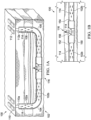
- FIG. 1A is a schematic diagram of a U-shaped wellbore 100 during fracturing operations.
- the U-shaped wellbore 100 is formed by drilling a first horizontal wellbore 102.
- the first horizontal wellbore 102 includes a vertical section 102a and a horizontal section 102b.
- the transition between the vertical section 102a and the horizontal section 102b is referred to as a heel 104.
- the heel 104 is illustrated as a hard 90° turn, but it can also be a gradual transition between the vertical section 102a and the horizontal section 102b without departing from this disclosure.
- the distal, or downhole, end of the first horizontal wellbore 102 is referred to as a toe 106.
- a second wellbore 108 having a vertical section is drilled into the toe 106 to complete the U-shaped wellbore 100. While illustrated as a straight, vertical wellbore, the second wellbore 108 can be slightly deviated without departing from this disclosure.
- the U-shaped wellbore 100 includes a horizontal section 102b, a first wellbore opening, and a second wellbore opening.
- a first topside facility 110 can be attached to or be otherwise fluidically coupled to the first wellbore opening, and a second topside facility 112 can be attached to or be otherwise fluidically connected to the second wellbore opening.
- the first topside facility 110 and the second topside facility 112 can include fracturing equipment such as manifolds, pumps, mixers, storage tanks, derricks, and other necessary support equipment for fracturing operations.
- fracturing fluid 114 is pumped from the first topside facility 110 and the second topside facility 112 simultaneously towards a fracturing point 116.
- the fracturing fluid pressure at the first topside facility 110 and the second topside facility 112 are such that the fracturing fluid from both locations is substantially the same pressure once the fluids reach the fracturing point 116.
- the maximum allowable pressure is governed by the type of completion.
- the wellbore completion may have a maximum pressure rating of up to 137895145.9 Pa (20000 psi) but due to safety factors at the topside facilities, the allowable maximum pressure may reach up to 89631844.6 Pa (13000 psi) 110316116.5 Pa (16000 psi) per well.
- Pumping fracturing fluid 114 from the first topside facility 110 and the second topside facility 112 simultaneously allows for greater flowrates and pressures at the fracture point 116 while maintaining a smaller physical surface footprint at each location.
- the first topside facility 110 and the second topside facility 112 each pump a fracturing fluid 114 that is substantially identical within typical mixing tolerances.
- the first topside facility 110 and the second topside facility 112 each pump a fracturing fluid 114 that are different from one another.
- fracturing fluid from the first topside facility 110 may include lubricants to reduce the pressure drop to the fracture point 116 if there is a difference in tubing diameter, tubing roughness, or tubing length between the first topside facility 110 and the fracture point 116 in comparison to the second topside facility 112.
- the fracture point 116 is substantially (within +/- 10%) halfway through a length of the horizontal section 102b within typical measurement errors.
- the pressure of the fracturing fluid at the first topside facility 110 and the second topside facility 112 is substantially identical within standard pressure measurement errors.
- FIG. 1B is a schematic diagram of a fracturing point 116 within the U-shaped wellbore 100.
- a fracture packer 150 is positioned adjacent to the fracture point 116.
- the fracture packer 150 includes a first fluid inlet 152 and a second fluid inlet 154.
- the first fluid inlet 152 receives fracturing fluid 114 from the first topside facility 110, while the second fluid inlet 154 receives fracturing fluid 114 from the second topside facility 112.
- the fracturing packer 150 then directs the fracturing fluid from both topside facilities out a fracturing nozzle 156 into the geologic formation, fracturing the formation.
- the fracture point 116 can be notched prior to fracturing to improve fracture propagation. Details with such implementations are described later within this disclosure.
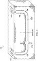
- FIG. 2 is a schematic diagram of the U-shaped wellbore 100 with a fracturing point 216 that is substantially offset from the middle of the horizontal section 102b (more than +/- 10% from the halfway point).
- the first pressure and the second pressure result in the first fracturing fluid from the first topside facility 110 and the second fracturing fluid from the second topside facility 112 intersecting at the fracture point 216 within the horizontal section 102b at a third pressure.
- the first fracturing fluid and the second fracturing fluid experience a first pressure drop and a second pressure drop, respectively, while traveling through their respective wellbores to the fracture point 216. As the distance traveled from each topside facility is different, the first pressure drop and the second pressure drop can be different as well.
- the first pressure at the first topside facility is different from the second pressure at the second topside facility.
- the fracture fluid at the first topside facility may not be at as great a pressure as the fracture fluid at the second topside facility.
- FIG. 3 is a schematic diagram of the U-shaped wellbore 100 with multiple fracturing points 316.
- a first fracture point 316a, a second fracture point 316b, a third fracture point 316c, and a fourth fracture point 316d are all located within the horizontal section 102b. While illustrated with four fracture points within the horizontal section 102b, more or less fracture points can be used. Alternatively or in addition, fracture points can exist in the first vertical section 102a or the second vertical wellbore 108 without departing from this disclosure. Regardless of the location of the individual fracture points, fluid is pumped from the first topside facility 110 and the second topside facility 112 simultaneously to the fracturing point of choice.
- Pressure is regulated separately at the first topside facility 110 and the second topside facility 112 so that pressure of the fracturing fluid 114 from both facilities is at substantially the same pressure at the fracture point of choice.
- the pressure at both the first topside facility 110 and the second topside facility 112 can be coordinated. For example, fluid can be pumped from the first topside facility 110 at a first specified pressure simultaneously as fluid is pumped from the second topside facility 112 at a second specified pressure. Both facilities can be aware of the operations occurring at one-another and can adjust operations to coordinate with one another in the event of an unexpected occurrence.
- first fracture point 316a, the second fracture point 316b, the third fracture point 316c, and the fourth fracture point 316d are fractured serially. That is, each fracture point is fractured one at a time. In some implementations, multiple fracture points can be fractured simultaneously.
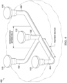
- FIG. 4 is a schematic diagram of a production field 400 with multiple U-shaped wellbores sharing a common central vertical wellbore, such as vertical wellbore 108.
- multiple horizontal wellbores such as the first horizontal wellbore 102, a second horizontal wellbore 404, and a third horizontal wellbore 406 each have a respective vertical section and a respective horizontal section.
- the vertical wellbore 108 is drilled to intersect with the toe of the first horizontal wellbore 102, the second horizontal wellbore 404, and the third horizontal wellbore 406.
- Fracturing fluid can be pumped from the topside facility 112 into any of the horizontal sections.
- Each of the additional wellbores has an additional topside facility.
- a third topside facility 412 is located at the top of the third wellbore 404 and a fourth topside facility 414 is located at the top of the fourth wellbore 406.
- fracturing fluid is pumped from the topside facility 112 and the respective topside facility for a particular horizontal section simultaneously.
- Multiple fracture points can exist in each horizontal section.
- fracture points can be present in any of the vertical wellbore sections. While illustrated with three horizontal wellbores and one vertical wellbore, greater or fewer wellbores can be used.
- the vertical wellbore can be used to produce from or monitor the various horizontal wellbore sections. In some implementations, the fracturing points in the various wellbores can be notched prior to fracturing operations.
- FIG. 5 is a schematic diagram of an example hydraulic notching tool 500 positioned within a U-shaped wellbore, such as U-shaped wellbore 100.
- the hydraulic notching tool is positioned within the wellbore 100 by a length of coiled tubing 502 extending from a topside facility.
- the hydraulic notching tool 500 is supplied with hydraulic notching fluid from the topside facility.
- the hydraulic notching fluid need not be the same as the fracturing fluid.
- the hydraulic notching fluid can include an abrasive suspended within the hydraulic notching fluid while the fracturing fluid can include proppant suspended in the fracturing fluid.
- the hydraulic notching fluid is the same as the fracturing fluid. Fluid selection for both fracturing and notching is determined one a case-by-case basis for each individual well based on rock properties, reservoir pressures, and other factors.
- the hydraulic tool 500 is configured to spray the notching fluid at sufficient pressure to create a notch in the wellbore 100. The pressure required is dependent upon the rock properties at the fracture point. In some implementations, the notch includes a point, corner, or other discontinuity that can create a stress concentration factor.
- the hydraulic notching tool 500 is configurable in-hole to notch at a specified angle 504. That is, the notching angle 504 can be adjusted after the hydraulic notching tool 500 is at the fracture point. In some implementations, the notching angle 504 is substantially perpendicular (+/- 5°) to the least principal stress of the wellbore section to be notched.
- FIGS. 6A-6C are schematic diagrams of the hydraulic notching tool 500 and various components.
- the hydraulic notching tool 500 includes a cylindrical drum 602 with a fluid nozzle 604 along an outer surface of the cylindrical drum 602.
- the fluid nozzle 604 is configured to be connected to a downhole end of a fluid conduit, such as the coiled tubing 502.
- the hydraulic notching tool includes multiple actuable fluid nozzles 604 fluidically connected to an interior of the cylindrical drum 602 and positioned around the outer circumference of the cylindrical drum 602.
- the fluid nozzles 604 are positioned to direct fluid away from the cylindrical drum 602 and towards a wall of the wellbore 100.
- a rotatable collar 606 is positioned in the center of the cylindrical drum 602.
- the rotatable collar 606 has an outer surface parallel to the inner surface of the cylindrical drum 602.
- an isolation packer 608 positioned uphole of the hydraulic notching tool 500.
- the isolation packer 608 fluidically isolates a section of the wellbore 100 to be notched from a remainder of the wellbore 100.
- Each of the sleeve plates 610 defines a hole 612 with a diameter smaller than a diameter of a corresponding dropped ball 614.
- a first sleeve plate 610a has a first hole with a first diameter smaller than a first dropped ball 614a of a first size.
- a second sleeve plate 610b has a second hole with a second diameter smaller than a second dropped ball 614b of a second size.
- Each of the sleeve plates 610 are configured to rotate around the rotatable collar 606 when a dropped ball 614 corresponding to one of the sleeve plates 610 is received. Each rotated sleeve plate is configured to direct fluid towards a respective nozzle in response to the rotation.
- the dropped ball 614 is a dissolvable dropped ball. The dissolvable dropped ball is configured to dissolve at a specified time within a notching fluid. In some implementations, notching fluid flow from the topside facility is timed to correspond with the desired fracture formation.
- the wellbore can be a U-shaped wellbore, such as the U-shaped wellbore 100, with a topside facility at each end, such as the first topside facility 110 and the second topside facility 112 ( FIG. 1 ).
- the fluid conduit (coiled tubing 502) can be a first fluid conduit extending from the first topside facility 110.
- the hydraulic notching tool 500 can be a first hydraulic notching tool 500 and the isolation packer 608 can be a first isolation packer 608.
- a second fluid conduit 552 can extend from the second topside facility 112.
- a second well-notching tool 550 identical or similar to the first hydraulic notching tool 500, is fluidically connected to a downhole end of the second fluid conduit 552 within the U-shaped wellbore.
- a second isolation packer 658 is positioned uphole of the second well-notching tool 550.
- the second isolation packer 658 fluidically isolates the section of the wellbore 100 to be notched from a remainder of the wellbore 100 toward the second topside facility 122.
- notching fluid can be pumped from both the first topside facility 110 and the second topside facility 112 simultaneously for notching operations.
- the first fluid notching tool 500 and the second notching tool 550 can be fluidically coupled to one another by a fluid conduit 616.
- the fluid conduit 616 can be used to equalize pressure between the first fluid notching tool 500 and the second hydraulic notching tool 550.
- higher nozzle pressures can be achieved by the first hydraulic notching tool 500 and the second hydraulic notching tool 550.
- the first fluid notching tool 500 and the second fluid notching tool 550 are substantially similar.
- the first fluid notching tool and the second fluid notching tool can include a similar outer housing.
- the second fluid notching tool 550 can have a different number of fluid nozzles or fluid nozzles at different angles than the first fluid notching tool 500.
- FIGS. 6D-6E are schematic diagrams of the notching tool drum in various stages of operation.
- Each of the sleeve plates 610 are configured to rotate around the rotatable collar 606 when a dropped ball 614 is received.
- Each rotated sleeve of the sleeve plates are configured to direct fluid towards a respective nozzle in response to the rotation.
- the sleeve plates 610 are in a first position.
- Each sleeve plate is coupled to a gate 620 across each of the corresponding nozzles 604. In the first position, each of the sleeve plates 610 holds their respective gates 620 in a closed position.
- FIG. 6E shows a gate 620 in an open position.
- the gate 620 is moved to an open position once the corresponding sleeve plate 610 has received a ball corresponding to that sleeve plate 610.
- the pressure build-up caused by the ball 614 being seated on the respective sleeve plate 610 causes the sleeve plate 610 and the corresponding gate 620 to move.
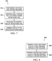
- FIG. 7 is a flowchart of an example method 700 for notching a wellbore that can be used with aspects of this disclosure.
- a notching tool such as the notching tool 500
- a fluid string such as the coiled tubing 502.
- a ball is dropped through the fluid string toward the notching tool.
- the dropped ball is sized to trigger a specified notching angle.
- a log of the wellbore is taken to determine an angle of the least principle stress within the wellbore.
- the specified notching angle is substantially perpendicular (+/- 5°) to the least principal stress of the wellbore.
- the dropped ball is received by the notching tool.
- receiving the dropped ball by the notching tool includes receiving the dropped ball by a sleeve plate within the notching tool.
- the sleeve plate receiving the dropped ball has a hole with a smaller diameter than the received dropped ball.
- a notch is formed at the specified notching angle. Forming the notch can include actuating the sleeve plate in response to receiving the dropped ball, and directing fluid through a nozzle that corresponds to the actuated sleeve plate.
- the dropped ball is a dissolvable dropped ball configured to dissolve after a pre-determined amount of time.
- the amount of time to notch is controlled by ceasing the flow of notching fluid from the topside facility at a specified time.
- the amount of time required to create the notch is dependent on pressures and flow rates of the notching fluid, and rock properties at the fracture point.
- the hydraulic notching tool is removed from the wellbore. Fracturing fluid can be pumped through the wellbore toward the notch once the hydraulic notching tool has been removed.
- the hydraulic tool can make multiple notches before being removed from the wellbore.
- multiple hydraulic notching tools can be used within a single wellbore simultaneously.
- FIG. 8 is a flowchart of an example method 800 that can be used with aspects of this disclosure.
- a second wellbore having a second vertical section that intersects with the distal end of the horizontal section is drilled.
- a first fracturing fluid is pumped at a first pressure through a first wellbore with a vertical section and a horizontal section having a first end, intersecting from the vertical section, and a distal end.
- a second fracturing fluid is pumped at a second pressure through a second wellbore that intersects with the distal end of the horizontal section.
- Pumping the second fracturing fluid occurs simultaneously as pumping the first fracturing fluid.
- the fracture point is halfway through a length of the horizontal section.
- the first fracturing fluid and the second fracturing fluid are substantially identical.
- the first pressure is different from the second pressure.
- the first pressure and the second pressure result in the first fracturing fluid and the second fracturing fluid intersecting at a fracture point within the horizontal section at a third pressure.
- the first fracturing fluid and the second fracturing fluid experience a first pressure drop and a second pressure drop, respectively, while traveling through their respective wellbores to the fracture point.
- Such a difference in pressure drop can occur when the fracture point is closer to one topside facility than the other.
- a third wellbore with a second vertical section and a second horizontal section intersects with the second wellbore.
- a third fracturing fluid can be pumped through the third wellbore.
- the second fracturing fluid is pumped through the second wellbore while simultaneously pumping the third fracturing fluid.
- the fracture point can be notched prior to pumping fracturing fluid through the first wellbore or the second wellbore, for example, using method 700. While previously described as notching with a hydraulic notching tool, other notching tools can be used without departing from this disclosure. In some implementations, such a notch can be substantially perpendicular (+/- 5°) to the least principal stress of the horizontal section.
Landscapes
- Life Sciences & Earth Sciences (AREA)
- Engineering & Computer Science (AREA)
- Geology (AREA)
- Mining & Mineral Resources (AREA)
- Physics & Mathematics (AREA)
- Environmental & Geological Engineering (AREA)
- Fluid Mechanics (AREA)
- General Life Sciences & Earth Sciences (AREA)
- Geochemistry & Mineralogy (AREA)
- Earth Drilling (AREA)
- Massaging Devices (AREA)
- Special Spraying Apparatus (AREA)
Claims (12)
- Bohrlochkerbwerkzeug (500), umfassend:eine zylindrische Trommel (602) mit einem Fluideinlass, der dazu konfiguriert ist, mit einem bohrlochseitigen Ende einer Fluidleitung (502) verbunden zu werden, wobei die zylindrische Trommel eine Außenfläche aufweist, entlang derer sich der Fluideinlass befindet, wobei die zylindrische Trommel (602) eine Mitte und eine Innenfläche aufweist;eine Vielzahl von Fluiddüsen (604), die fluidisch mit dem Inneren der zylindrischen Trommel (602) verbunden und um einen Außenumfang der zylindrischen Trommel (602) angeordnet sind, wobei jede der Vielzahl von Fluiddüsen (604) so angeordnet ist, dass sie Fluid von der zylindrischen Trommel (602) weg und in Richtung einer Bohrlochwand leitet, um eine Kerbe in einem vorgegebenen Kerbwinkel (504) zu bilden;einen drehbaren Kragen (606), der in der Mitte der zylindrischen Trommel (602) angeordnet ist, wobei der drehbare Kragen (602) eine Außenfläche parallel zur Innenfläche der zylindrischen Trommel (602) aufweist; undeine Vielzahl von Hülsenplatten (610), die zwischen der Innenfläche der zylindrischen Trommel (602) und der Außenfläche des drehbaren Kragens (606) angeordnet sind, wobei jede der Vielzahl von Hülsenplatten (610) ein Loch (612) mit einem Durchmesser definiert, der kleiner als der Durchmesser einer entsprechenden Kugel (614) ist, die durch die Fluidleitung (502) fallen gelassen wird, wobei die entsprechende fallen gelassene Kugel so bemessen ist, dass sie einen vorgegebenen Kerbwinkel (504) auslöst;wobei jede der Vielzahl von Hülsenplatten (610) mit einem jeweiligen Gatter (620) über einer jeweiligen Fluiddüse der Vielzahl von Fluiddüsen (604) gekoppelt ist, und wobei jede der Vielzahl von Hülsenplatten (610) dazu konfiguriert ist,i) das jeweilige Gatter (620) in einer geschlossenen Position zu halten, und wenn die entsprechende fallen gelassene Kugel (614) empfangen wird und als Reaktion auf einen Druckaufbau, der dadurch verursacht wird, dass die Kugel (614) auf der Hülsenplatte (610) sitzt,ii) sich um den drehbaren Kragen (606) zu drehen, um das jeweilige Gatter in eine geöffnete Position zu bewegen, um Fluid in Richtung der jeweiligen Fluiddüse (610) zu leiten.
- Bohrlochkerbwerkzeug nach Anspruch 1, wobei eine erste Hülsenplatte der Vielzahl von Hülsenplatten ein erstes Loch mit einem ersten Durchmesser aufweist, der kleiner als eine erste fallen gelassene Kugel einer ersten Größe ist, und eine zweite Hülsenplatte der Vielzahl von Hülsenplatten ein zweites Loch mit einem zweiten Durchmesser aufweist, der kleiner als eine zweite fallen gelassene Kugel einer zweiten Größe ist.
- Bohrlochkerbwerkzeug nach Anspruch 1, wobei die fallen gelassene Kugel eine auflösbare fallen gelassene Kugel ist, wobei die auflösbare fallen gelassene Kugel dazu konfiguriert ist, sich zu einem vorgegebenen Zeitpunkt innerhalb einer Kerbflüssigkeit aufzulösen.
- Verfahren (700) zum Kerben eines Bohrlochs, wobei das Verfahren umfasst:Anordnen (702) eines Kerbwerkzeugs (500) innerhalb eines Bohrlochs (100) am distalen Ende eines Fluidstrangs, wobei das Kerbwerkzeug im Bohrloch so konfigurierbar ist, dass es in einem Kerbwinkel (504) kerbt, und der Kerbwinkel (504) einstellbar ist, nachdem sich das Kerbwerkzeug (500) an einer Bruchstelle innerhalb des Bohrlochs (100) befindet;Einstellen des Kerbwinkels durch Fallenlassen (704) einer Kugel durch den Fluidstrang in Richtung des Kerbwerkzeugs (500), wobei die fallen gelassene Kugel so bemessen ist, dass sie einen vorgegebenen Kerbwinkel (504) auslöst;Empfangen (706) der fallen gelassenen Kugel durch eine Hülsenplatte innerhalb des Kerbwerkzeugs (500), wobei die Hülsenplatte ein Loch mit einem kleineren Durchmesser als die empfangene fallen gelassene Kugel aufweist;Betätigen der Hülsenplatte als Reaktion auf den Empfang der fallen gelassenen Kugel, wobei die Hülsenplatte mit einem jeweiligen Gatter über einer jeweiligen Düse gekoppelt ist und wobei die Hülsenplatte als Reaktion auf einen Druckaufbau betätigt wird, der dadurch verursacht wird, dass die fallen gelassene Kugel (614) auf der Hülsenplatte (610) sitzt, was dazu führt, dass sich die Hülsenplatte dreht und das jeweilige Gatter in eine geöffnete Position bewegt; undLeiten von Fluid durch die jeweilige Düse, um (708) eine Kerbe in dem vorgegebenen Kerbwinkel (504) zu bilden.
- Verfahren nach Anspruch 4, ferner umfassend das Bestimmen eines Winkels der geringsten Hauptspannung innerhalb des Bohrlochs.
- Verfahren nach Anspruch 4, wobei der vorgegebene Kerbwinkel rechtwinklig zur geringsten Hauptspannung des Bohrlochs ist.
- Verfahren nach Anspruch 4, wobei die fallen gelassene Kugel eine auflösbare fallen gelassene Kugel ist, die dazu konfiguriert ist, sich nach einer vorgegebenen Zeitspanne aufzulösen.
- Verfahren nach Anspruch 4, ferner umfassend:Entfernen des Kerbwerkzeugs aus dem Bohrloch; undPumpen eines Frakturierfluids durch das Bohrloch in Richtung der Kerbe.
- Verfahren nach Anspruch 8, wobei das Bohrloch ein U-förmiges Bohrloch mit einem ersten Ende, einem zweiten Ende und einem horizontalen Bohrlochabschnitt ist.
- Verfahren nach Anspruch 9, wobei das Pumpen des Frakturierfluids umfasst:Pumpen von Frakturierfluid von einem ersten Ende des Bohrlochs; undPumpen von Frakturierfluid von einem zweiten Ende des Bohrlochs.
- Bohrlochkerbsystem, umfassend:eine Fluidleitung (502), die sich von einer oberirdischen Anlage (110) in ein Bohrloch (100) erstreckt;ein Bohrlochkerbwerkzeug (500) nach einem der Ansprüche 1 bis 3, wobei das Bohrlochkerbwerkzeug (500) fluidisch mit einem bohrlochseitigen Ende der Fluidleitung (502) innerhalb eines Bohrlochs (100) verbunden und dort angeordnet ist; undeinen Isolationspacker (608), der oberhalb des Bohrlochkerbwerkzeugs (500) angeordnet ist, wobei der Isolationspacker (608) einen zu kerbenden Abschnitt des Bohrlochs (100) fluidisch vom Rest des Bohrlochs (100) isoliert.
- Bohrlochkerbsystem nach Anspruch 11, wobei das Bohrloch ein U-förmiges Bohrloch mit einem ersten Ende und einem zweiten Ende ist, die oberirdische Anlage eine erste oberirdische Anlage ist, die sich am ersten Ende des U-förmigen Bohrlochs befindet, die Fluidleitung eine erste Fluidleitung ist, die sich von der ersten oberirdischen Anlage erstreckt, das Bohrlochkerbwerkzeug ein erstes Bohrlochkerbwerkzeug ist, der Isolationspacker ein erster Isolationspacker ist, wobei das System ferner umfasst:eine zweite Fluidleitung, die sich von einer zweiten oberirdischen Anlage erstreckt, die am zweiten Ende des Bohrlochs angeordnet ist;ein zweites Bohrlochkerbwerkzeug, identisch mit dem ersten Bohrlochkerbwerkzeug, das fluidisch mit einem bohrlochseitigen Ende der zweiten Fluidleitung innerhalb des U-förmigen Bohrlochs verbunden ist; undeinen zweiten Isolationspacker, der oberhalb des zweiten Bohrlochkerbwerkzeugs angeordnet ist, wobei der Isolationspacker den zu kerbenden Abschnitt des Bohrlochs fluidisch vom Rest des Bohrlochs in Richtung der zweiten oberirdischen Anlage isoliert.
Applications Claiming Priority (2)
| Application Number | Priority Date | Filing Date | Title |
|---|---|---|---|
| US16/272,699 US10612355B1 (en) | 2019-02-11 | 2019-02-11 | Stimulating u-shape wellbores |
| PCT/US2020/017610 WO2020167724A1 (en) | 2019-02-11 | 2020-02-11 | Stimulating u-shape wellbores |
Publications (2)
| Publication Number | Publication Date |
|---|---|
| EP3924596A1 EP3924596A1 (de) | 2021-12-22 |
| EP3924596B1 true EP3924596B1 (de) | 2024-11-06 |
Family
ID=69771224
Family Applications (1)
| Application Number | Title | Priority Date | Filing Date |
|---|---|---|---|
| EP20709990.4A Active EP3924596B1 (de) | 2019-02-11 | 2020-02-11 | Stimulierung von u-förmigen bohrlöchern |
Country Status (4)
| Country | Link |
|---|---|
| US (3) | US10612355B1 (de) |
| EP (1) | EP3924596B1 (de) |
| SA (1) | SA521430015B1 (de) |
| WO (1) | WO2020167724A1 (de) |
Families Citing this family (12)
| Publication number | Priority date | Publication date | Assignee | Title |
|---|---|---|---|---|
| US10612355B1 (en) | 2019-02-11 | 2020-04-07 | Saudi Arabian Oil Company | Stimulating u-shape wellbores |
| US11035212B2 (en) | 2019-02-11 | 2021-06-15 | Saudi Arabian Oil Company | Stimulating U-shape wellbores |
| US11460330B2 (en) | 2020-07-06 | 2022-10-04 | Saudi Arabian Oil Company | Reducing noise in a vortex flow meter |
| US11692425B2 (en) * | 2020-08-04 | 2023-07-04 | Schlumberger Technology Corporation | Method and downhole apparatus to accelerate wormhole initiation and propagation during matrix acidizing of a subterranean rock formation |
| US11525723B2 (en) | 2020-08-31 | 2022-12-13 | Saudi Arabian Oil Company | Determining fluid properties |
| US11428557B2 (en) | 2020-08-31 | 2022-08-30 | Saudi Arabian Oil Company | Determining fluid properties |
| US11542815B2 (en) | 2020-11-30 | 2023-01-03 | Saudi Arabian Oil Company | Determining effect of oxidative hydraulic fracturing |
| US11649702B2 (en) | 2020-12-03 | 2023-05-16 | Saudi Arabian Oil Company | Wellbore shaped perforation assembly |
| US12071814B2 (en) | 2020-12-07 | 2024-08-27 | Saudi Arabian Oil Company | Wellbore notching assembly |
| US11619127B1 (en) | 2021-12-06 | 2023-04-04 | Saudi Arabian Oil Company | Wellhead acoustic insulation to monitor hydraulic fracturing |
| WO2024015057A1 (en) * | 2022-07-13 | 2024-01-18 | Schlumberger Technology Corporation | Method and downhole apparatus for matrix acidizing of a subterranean rock formation |
| CN116006121B (zh) * | 2023-03-23 | 2024-04-16 | 西安石油大佳润实业有限公司 | 绳结暂堵剂自动投加装置 |
Family Cites Families (41)
| Publication number | Priority date | Publication date | Assignee | Title |
|---|---|---|---|---|
| US2699212A (en) | 1948-09-01 | 1955-01-11 | Newton B Dismukes | Method of forming passageways extending from well bores |
| US3254720A (en) | 1964-10-08 | 1966-06-07 | Gulf Research Development Co | Apparatus for cutting a notch in a subsurface formation |
| US4262745A (en) | 1979-12-14 | 1981-04-21 | Exxon Production Research Company | Steam stimulation process for recovering heavy oil |
| FR2483005A1 (fr) | 1980-05-23 | 1981-11-27 | Inst Francais Du Petrole | Procede pour fracturer hydrauliquement une formation geologique selon une direction predeterminee |
| US4390067A (en) | 1981-04-06 | 1983-06-28 | Exxon Production Research Co. | Method of treating reservoirs containing very viscous crude oil or bitumen |
| US4754808A (en) | 1986-06-20 | 1988-07-05 | Conoco Inc. | Methods for obtaining well-to-well flow communication |
| US4662440A (en) | 1986-06-20 | 1987-05-05 | Conoco Inc. | Methods for obtaining well-to-well flow communication |
| EP0251881B1 (de) | 1986-06-26 | 1992-04-29 | Institut Français du Pétrole | Gewinnungsverfahren für eine in einer geologischen Formation enthaltene zu produzierende Flüssigkeit |
| US4687061A (en) | 1986-12-08 | 1987-08-18 | Mobil Oil Corporation | Stimulation of earth formations surrounding a deviated wellbore by sequential hydraulic fracturing |
| US4974675A (en) | 1990-03-08 | 1990-12-04 | Halliburton Company | Method of fracturing horizontal wells |
| US5074360A (en) | 1990-07-10 | 1991-12-24 | Guinn Jerry H | Method for repoducing hydrocarbons from low-pressure reservoirs |
| US5228510A (en) | 1992-05-20 | 1993-07-20 | Mobil Oil Corporation | Method for enhancement of sequential hydraulic fracturing using control pulse fracturing |
| US5450902A (en) | 1993-05-14 | 1995-09-19 | Matthews; Cameron M. | Method and apparatus for producing and drilling a well |
| US6729394B1 (en) | 1997-05-01 | 2004-05-04 | Bp Corporation North America Inc. | Method of producing a communicating horizontal well network |
| US6119776A (en) | 1998-02-12 | 2000-09-19 | Halliburton Energy Services, Inc. | Methods of stimulating and producing multiple stratified reservoirs |
| US6095244A (en) | 1998-02-12 | 2000-08-01 | Halliburton Energy Services, Inc. | Methods of stimulating and producing multiple stratified reservoirs |
| US6425448B1 (en) | 2001-01-30 | 2002-07-30 | Cdx Gas, L.L.P. | Method and system for accessing subterranean zones from a limited surface area |
| US6488087B2 (en) | 2000-03-14 | 2002-12-03 | Halliburton Energy Services, Inc. | Field development methods |
| RU2211318C2 (ru) | 2000-11-21 | 2003-08-27 | Открытое акционерное общество "Всероссийский нефтегазовый научно-исследовательский институт им. акад. А.П. Крылова" | Способ добычи вязкой нефти при тепловом воздействии на пласт |
| US7419005B2 (en) | 2003-07-30 | 2008-09-02 | Saudi Arabian Oil Company | Method of stimulating long horizontal wells to improve well productivity |
| US7370696B2 (en) | 2004-09-07 | 2008-05-13 | Saudi Arabian Oil Company | Wellbore system for producing fluid |
| UA100837C2 (ru) | 2005-08-19 | 2013-02-11 | Эксонмобил Апстрим Рисерч Компани | Способ обработки пласта для интенсификации притока из скважин |
| CA2625429C (en) | 2005-11-03 | 2014-07-22 | Saudi Arabian Oil Company | Continuous reservoir monitoring for fluid pathways using 3d microseismic data |
| EA200801333A1 (ru) | 2005-11-16 | 2009-02-27 | Шелл Интернэшнл Рисерч Маатсхаппий Б.В. | Система стволов скважин |
| US8261834B2 (en) | 2007-04-30 | 2012-09-11 | Schlumberger Technology Corporation | Well treatment using electric submersible pumping system |
| US8631872B2 (en) | 2009-09-24 | 2014-01-21 | Halliburton Energy Services, Inc. | Complex fracturing using a straddle packer in a horizontal wellbore |
| US9063252B2 (en) | 2009-03-13 | 2015-06-23 | Saudi Arabian Oil Company | System, method, and nanorobot to explore subterranean geophysical formations |
| US20110284214A1 (en) | 2010-05-19 | 2011-11-24 | Ayoub Joseph A | Methods and tools for multiple fracture placement along a wellbore |
| US9187992B2 (en) | 2012-04-24 | 2015-11-17 | Schlumberger Technology Corporation | Interacting hydraulic fracturing |
| US20140352968A1 (en) | 2013-06-03 | 2014-12-04 | Cameron International Corporation | Multi-well simultaneous fracturing system |
| US20160230523A9 (en) | 2013-08-15 | 2016-08-11 | Shell Oil Company | Mechanized slot drilling |
| US20160201440A1 (en) | 2015-01-13 | 2016-07-14 | Schlumberger Technology Corporation | Fracture initiation with auxiliary notches |
| WO2018013096A1 (en) | 2016-07-13 | 2018-01-18 | Halliburton Energy Services, Inc. | Methods for reducing fluid communication between wells |
| US20180119533A1 (en) | 2016-10-28 | 2018-05-03 | Saudi Arabian Oil Company | Wellbore System With Lateral Wells |
| US11215011B2 (en) * | 2017-03-20 | 2022-01-04 | Saudi Arabian Oil Company | Notching a wellbore while drilling |
| US11326436B2 (en) | 2017-03-24 | 2022-05-10 | Donald J. FRY | Enhanced wellbore design and methods |
| US10738600B2 (en) * | 2017-05-19 | 2020-08-11 | Baker Hughes, A Ge Company, Llc | One run reservoir evaluation and stimulation while drilling |
| WO2019143917A2 (en) | 2018-01-18 | 2019-07-25 | Saudi Arabian Oil Company | Tracers for petroleum reservoirs |
| US10458213B1 (en) | 2018-07-17 | 2019-10-29 | Dynaenergetics Gmbh & Co. Kg | Positioning device for shaped charges in a perforating gun module |
| US11156071B2 (en) | 2018-07-18 | 2021-10-26 | Saudi Arabian Oil Company | Method of subterranean fracturing |
| US10612355B1 (en) | 2019-02-11 | 2020-04-07 | Saudi Arabian Oil Company | Stimulating u-shape wellbores |
-
2019
- 2019-02-11 US US16/272,699 patent/US10612355B1/en active Active
- 2019-11-07 US US16/676,890 patent/US11078770B2/en active Active
- 2019-11-07 US US16/676,910 patent/US10920554B2/en active Active
-
2020
- 2020-02-11 EP EP20709990.4A patent/EP3924596B1/de active Active
- 2020-02-11 WO PCT/US2020/017610 patent/WO2020167724A1/en not_active Ceased
-
2021
- 2021-08-10 SA SA521430015A patent/SA521430015B1/ar unknown
Also Published As
| Publication number | Publication date |
|---|---|
| WO2020167724A1 (en) | 2020-08-20 |
| SA521430015B1 (ar) | 2024-03-10 |
| US10920554B2 (en) | 2021-02-16 |
| US20200256175A1 (en) | 2020-08-13 |
| US10612355B1 (en) | 2020-04-07 |
| US20200256174A1 (en) | 2020-08-13 |
| EP3924596A1 (de) | 2021-12-22 |
| US11078770B2 (en) | 2021-08-03 |
Similar Documents
| Publication | Publication Date | Title |
|---|---|---|
| EP3924596B1 (de) | Stimulierung von u-förmigen bohrlöchern | |
| US10683740B2 (en) | Method of avoiding frac hits during formation stimulation | |
| US11008843B2 (en) | System and methods for constructing and fracture stimulating multiple ultra-short radius laterals from a parent well | |
| US10151172B1 (en) | Pressure perforated well casing collar and method of use | |
| CA2671096C (en) | System and method for longitudinal and lateral jetting in a wellbore | |
| WO2020167722A1 (en) | Fracturing u-shape wellbores | |
| US9810047B2 (en) | Re-fracturing bottom hole assembly and method | |
| EP3126623B1 (de) | Herstellung von mehrseitigen bohrlöchern | |
| US20170260834A1 (en) | Multilateral access with real-time data transmission | |
| WO2014078663A2 (en) | High power laser hydraulic fructuring, stimulation, tools systems and methods | |
| US9926774B2 (en) | Methods of producing with multi-sidetracked mother wellbores | |
| CN105143597A (zh) | 多级井的隔离和压裂 | |
| US20190226282A1 (en) | Drilling and stimulation of subterranean formation | |
| US9353597B2 (en) | Apparatus and method for isolating flow in a downhole tool assembly | |
| US11840909B2 (en) | Attaining access to compromised fractured production regions at an oilfield | |
| CN112020593B (zh) | 用于井下操作的带端口套管接箍以及用于进入地层的方法 | |
| WO2019140287A2 (en) | Method of avoiding frac hits during formation stimulation | |
| US20180274341A1 (en) | Pressure perforated well casing systems | |
| CA3088309C (en) | Method for avoiding frac hits during formation stimulation | |
| Irawan et al. | Design Selection of Multi-Stage Fracturing Horizontal Wells in K-Field, Central Sumatra Basin, Indonesia |
Legal Events
| Date | Code | Title | Description |
|---|---|---|---|
| STAA | Information on the status of an ep patent application or granted ep patent |
Free format text: STATUS: UNKNOWN |
|
| STAA | Information on the status of an ep patent application or granted ep patent |
Free format text: STATUS: THE INTERNATIONAL PUBLICATION HAS BEEN MADE |
|
| PUAI | Public reference made under article 153(3) epc to a published international application that has entered the european phase |
Free format text: ORIGINAL CODE: 0009012 |
|
| STAA | Information on the status of an ep patent application or granted ep patent |
Free format text: STATUS: REQUEST FOR EXAMINATION WAS MADE |
|
| 17P | Request for examination filed |
Effective date: 20210831 |
|
| AK | Designated contracting states |
Kind code of ref document: A1 Designated state(s): AL AT BE BG CH CY CZ DE DK EE ES FI FR GB GR HR HU IE IS IT LI LT LU LV MC MK MT NL NO PL PT RO RS SE SI SK SM TR |
|
| DAV | Request for validation of the european patent (deleted) | ||
| DAX | Request for extension of the european patent (deleted) | ||
| STAA | Information on the status of an ep patent application or granted ep patent |
Free format text: STATUS: EXAMINATION IS IN PROGRESS |
|
| 17Q | First examination report despatched |
Effective date: 20220908 |
|
| P01 | Opt-out of the competence of the unified patent court (upc) registered |
Effective date: 20230528 |
|
| GRAP | Despatch of communication of intention to grant a patent |
Free format text: ORIGINAL CODE: EPIDOSNIGR1 |
|
| STAA | Information on the status of an ep patent application or granted ep patent |
Free format text: STATUS: GRANT OF PATENT IS INTENDED |
|
| INTG | Intention to grant announced |
Effective date: 20240221 |
|
| RIN1 | Information on inventor provided before grant (corrected) |
Inventor name: NOUI-MEHIDI, MOHAMED NABIL Inventor name: ALRUWAILI, KHALID MOHAMMED |
|
| GRAJ | Information related to disapproval of communication of intention to grant by the applicant or resumption of examination proceedings by the epo deleted |
Free format text: ORIGINAL CODE: EPIDOSDIGR1 |
|
| STAA | Information on the status of an ep patent application or granted ep patent |
Free format text: STATUS: EXAMINATION IS IN PROGRESS |
|
| GRAP | Despatch of communication of intention to grant a patent |
Free format text: ORIGINAL CODE: EPIDOSNIGR1 |
|
| STAA | Information on the status of an ep patent application or granted ep patent |
Free format text: STATUS: GRANT OF PATENT IS INTENDED |
|
| INTC | Intention to grant announced (deleted) | ||
| INTG | Intention to grant announced |
Effective date: 20240709 |
|
| GRAS | Grant fee paid |
Free format text: ORIGINAL CODE: EPIDOSNIGR3 |
|
| GRAA | (expected) grant |
Free format text: ORIGINAL CODE: 0009210 |
|
| STAA | Information on the status of an ep patent application or granted ep patent |
Free format text: STATUS: THE PATENT HAS BEEN GRANTED |
|
| AK | Designated contracting states |
Kind code of ref document: B1 Designated state(s): AL AT BE BG CH CY CZ DE DK EE ES FI FR GB GR HR HU IE IS IT LI LT LU LV MC MK MT NL NO PL PT RO RS SE SI SK SM TR |
|
| REG | Reference to a national code |
Ref country code: GB Ref legal event code: FG4D |
|
| REG | Reference to a national code |
Ref country code: CH Ref legal event code: EP |
|
| REG | Reference to a national code |
Ref country code: DE Ref legal event code: R096 Ref document number: 602020040768 Country of ref document: DE |
|
| REG | Reference to a national code |
Ref country code: IE Ref legal event code: FG4D |
|
| REG | Reference to a national code |
Ref country code: LT Ref legal event code: MG9D |
|
| REG | Reference to a national code |
Ref country code: NL Ref legal event code: MP Effective date: 20241106 |
|
| PG25 | Lapsed in a contracting state [announced via postgrant information from national office to epo] |
Ref country code: PT Free format text: LAPSE BECAUSE OF FAILURE TO SUBMIT A TRANSLATION OF THE DESCRIPTION OR TO PAY THE FEE WITHIN THE PRESCRIBED TIME-LIMIT Effective date: 20250306 Ref country code: IS Free format text: LAPSE BECAUSE OF FAILURE TO SUBMIT A TRANSLATION OF THE DESCRIPTION OR TO PAY THE FEE WITHIN THE PRESCRIBED TIME-LIMIT Effective date: 20250306 Ref country code: HR Free format text: LAPSE BECAUSE OF FAILURE TO SUBMIT A TRANSLATION OF THE DESCRIPTION OR TO PAY THE FEE WITHIN THE PRESCRIBED TIME-LIMIT Effective date: 20241106 |
|
| PG25 | Lapsed in a contracting state [announced via postgrant information from national office to epo] |
Ref country code: FI Free format text: LAPSE BECAUSE OF FAILURE TO SUBMIT A TRANSLATION OF THE DESCRIPTION OR TO PAY THE FEE WITHIN THE PRESCRIBED TIME-LIMIT Effective date: 20241106 Ref country code: NL Free format text: LAPSE BECAUSE OF FAILURE TO SUBMIT A TRANSLATION OF THE DESCRIPTION OR TO PAY THE FEE WITHIN THE PRESCRIBED TIME-LIMIT Effective date: 20241106 |
|
| REG | Reference to a national code |
Ref country code: AT Ref legal event code: MK05 Ref document number: 1739539 Country of ref document: AT Kind code of ref document: T Effective date: 20241106 |
|
| PG25 | Lapsed in a contracting state [announced via postgrant information from national office to epo] |
Ref country code: BG Free format text: LAPSE BECAUSE OF FAILURE TO SUBMIT A TRANSLATION OF THE DESCRIPTION OR TO PAY THE FEE WITHIN THE PRESCRIBED TIME-LIMIT Effective date: 20241106 |
|
| PG25 | Lapsed in a contracting state [announced via postgrant information from national office to epo] |
Ref country code: ES Free format text: LAPSE BECAUSE OF FAILURE TO SUBMIT A TRANSLATION OF THE DESCRIPTION OR TO PAY THE FEE WITHIN THE PRESCRIBED TIME-LIMIT Effective date: 20241106 |
|
| PG25 | Lapsed in a contracting state [announced via postgrant information from national office to epo] |
Ref country code: LV Free format text: LAPSE BECAUSE OF FAILURE TO SUBMIT A TRANSLATION OF THE DESCRIPTION OR TO PAY THE FEE WITHIN THE PRESCRIBED TIME-LIMIT Effective date: 20241106 Ref country code: GR Free format text: LAPSE BECAUSE OF FAILURE TO SUBMIT A TRANSLATION OF THE DESCRIPTION OR TO PAY THE FEE WITHIN THE PRESCRIBED TIME-LIMIT Effective date: 20250207 Ref country code: AT Free format text: LAPSE BECAUSE OF FAILURE TO SUBMIT A TRANSLATION OF THE DESCRIPTION OR TO PAY THE FEE WITHIN THE PRESCRIBED TIME-LIMIT Effective date: 20241106 |
|
| PG25 | Lapsed in a contracting state [announced via postgrant information from national office to epo] |
Ref country code: PL Free format text: LAPSE BECAUSE OF FAILURE TO SUBMIT A TRANSLATION OF THE DESCRIPTION OR TO PAY THE FEE WITHIN THE PRESCRIBED TIME-LIMIT Effective date: 20241106 |
|
| PG25 | Lapsed in a contracting state [announced via postgrant information from national office to epo] |
Ref country code: RS Free format text: LAPSE BECAUSE OF FAILURE TO SUBMIT A TRANSLATION OF THE DESCRIPTION OR TO PAY THE FEE WITHIN THE PRESCRIBED TIME-LIMIT Effective date: 20250206 |
|
| PG25 | Lapsed in a contracting state [announced via postgrant information from national office to epo] |
Ref country code: SM Free format text: LAPSE BECAUSE OF FAILURE TO SUBMIT A TRANSLATION OF THE DESCRIPTION OR TO PAY THE FEE WITHIN THE PRESCRIBED TIME-LIMIT Effective date: 20241106 |
|
| PG25 | Lapsed in a contracting state [announced via postgrant information from national office to epo] |
Ref country code: DK Free format text: LAPSE BECAUSE OF FAILURE TO SUBMIT A TRANSLATION OF THE DESCRIPTION OR TO PAY THE FEE WITHIN THE PRESCRIBED TIME-LIMIT Effective date: 20241106 |
|
| PG25 | Lapsed in a contracting state [announced via postgrant information from national office to epo] |
Ref country code: EE Free format text: LAPSE BECAUSE OF FAILURE TO SUBMIT A TRANSLATION OF THE DESCRIPTION OR TO PAY THE FEE WITHIN THE PRESCRIBED TIME-LIMIT Effective date: 20241106 |
|
| PG25 | Lapsed in a contracting state [announced via postgrant information from national office to epo] |
Ref country code: RO Free format text: LAPSE BECAUSE OF FAILURE TO SUBMIT A TRANSLATION OF THE DESCRIPTION OR TO PAY THE FEE WITHIN THE PRESCRIBED TIME-LIMIT Effective date: 20241106 |
|
| PG25 | Lapsed in a contracting state [announced via postgrant information from national office to epo] |
Ref country code: SK Free format text: LAPSE BECAUSE OF FAILURE TO SUBMIT A TRANSLATION OF THE DESCRIPTION OR TO PAY THE FEE WITHIN THE PRESCRIBED TIME-LIMIT Effective date: 20241106 |
|
| PG25 | Lapsed in a contracting state [announced via postgrant information from national office to epo] |
Ref country code: CZ Free format text: LAPSE BECAUSE OF FAILURE TO SUBMIT A TRANSLATION OF THE DESCRIPTION OR TO PAY THE FEE WITHIN THE PRESCRIBED TIME-LIMIT Effective date: 20241106 |
|
| PG25 | Lapsed in a contracting state [announced via postgrant information from national office to epo] |
Ref country code: IT Free format text: LAPSE BECAUSE OF FAILURE TO SUBMIT A TRANSLATION OF THE DESCRIPTION OR TO PAY THE FEE WITHIN THE PRESCRIBED TIME-LIMIT Effective date: 20241106 |
|
| REG | Reference to a national code |
Ref country code: DE Ref legal event code: R097 Ref document number: 602020040768 Country of ref document: DE |
|
| REG | Reference to a national code |
Ref country code: DE Ref legal event code: R119 Ref document number: 602020040768 Country of ref document: DE |
|
| PG25 | Lapsed in a contracting state [announced via postgrant information from national office to epo] |
Ref country code: SE Free format text: LAPSE BECAUSE OF FAILURE TO SUBMIT A TRANSLATION OF THE DESCRIPTION OR TO PAY THE FEE WITHIN THE PRESCRIBED TIME-LIMIT Effective date: 20241106 |
|
| PLBE | No opposition filed within time limit |
Free format text: ORIGINAL CODE: 0009261 |
|
| STAA | Information on the status of an ep patent application or granted ep patent |
Free format text: STATUS: NO OPPOSITION FILED WITHIN TIME LIMIT |
|
| PG25 | Lapsed in a contracting state [announced via postgrant information from national office to epo] |
Ref country code: MC Free format text: LAPSE BECAUSE OF FAILURE TO SUBMIT A TRANSLATION OF THE DESCRIPTION OR TO PAY THE FEE WITHIN THE PRESCRIBED TIME-LIMIT Effective date: 20241106 |
|
| REG | Reference to a national code |
Ref country code: CH Ref legal event code: PL |
|
| 26N | No opposition filed |
Effective date: 20250807 |
|
| PG25 | Lapsed in a contracting state [announced via postgrant information from national office to epo] |
Ref country code: LU Free format text: LAPSE BECAUSE OF NON-PAYMENT OF DUE FEES Effective date: 20250211 |
|
| PG25 | Lapsed in a contracting state [announced via postgrant information from national office to epo] |
Ref country code: CH Free format text: LAPSE BECAUSE OF NON-PAYMENT OF DUE FEES Effective date: 20250228 |
|
| GBPC | Gb: european patent ceased through non-payment of renewal fee |
Effective date: 20250211 |
|
| REG | Reference to a national code |
Ref country code: BE Ref legal event code: MM Effective date: 20250228 |
|
| PG25 | Lapsed in a contracting state [announced via postgrant information from national office to epo] |
Ref country code: DE Free format text: LAPSE BECAUSE OF NON-PAYMENT OF DUE FEES Effective date: 20250902 |
|
| PG25 | Lapsed in a contracting state [announced via postgrant information from national office to epo] |
Ref country code: GB Free format text: LAPSE BECAUSE OF NON-PAYMENT OF DUE FEES Effective date: 20250211 |
|
| PG25 | Lapsed in a contracting state [announced via postgrant information from national office to epo] |
Ref country code: FR Free format text: LAPSE BECAUSE OF NON-PAYMENT OF DUE FEES Effective date: 20250228 |
|
| PG25 | Lapsed in a contracting state [announced via postgrant information from national office to epo] |
Ref country code: BE Free format text: LAPSE BECAUSE OF NON-PAYMENT OF DUE FEES Effective date: 20250228 |
|
| PG25 | Lapsed in a contracting state [announced via postgrant information from national office to epo] |
Ref country code: IE Free format text: LAPSE BECAUSE OF NON-PAYMENT OF DUE FEES Effective date: 20250211 |
|
| PGFP | Annual fee paid to national office [announced via postgrant information from national office to epo] |
Ref country code: NO Payment date: 20260211 Year of fee payment: 7 |