EP3924153B1 - Shaving system including a cleaning device for cleaning a shaving device - Google Patents
Shaving system including a cleaning device for cleaning a shaving device Download PDFInfo
- Publication number
- EP3924153B1 EP3924153B1 EP20743721.1A EP20743721A EP3924153B1 EP 3924153 B1 EP3924153 B1 EP 3924153B1 EP 20743721 A EP20743721 A EP 20743721A EP 3924153 B1 EP3924153 B1 EP 3924153B1
- Authority
- EP
- European Patent Office
- Prior art keywords
- shaving
- unit
- hair
- cleaning
- annular
- Prior art date
- Legal status (The legal status is an assumption and is not a legal conclusion. Google has not performed a legal analysis and makes no representation as to the accuracy of the status listed.)
- Active
Links
Images

Classifications
-
- A—HUMAN NECESSITIES
- A45—HAND OR TRAVELLING ARTICLES
- A45D—HAIRDRESSING OR SHAVING EQUIPMENT; EQUIPMENT FOR COSMETICS OR COSMETIC TREATMENTS, e.g. FOR MANICURING OR PEDICURING
- A45D27/00—Shaving accessories
- A45D27/46—Devices specially adapted for cleaning or disinfecting shavers or razors
-
- B—PERFORMING OPERATIONS; TRANSPORTING
- B26—HAND CUTTING TOOLS; CUTTING; SEVERING
- B26B—HAND-HELD CUTTING TOOLS NOT OTHERWISE PROVIDED FOR
- B26B19/00—Clippers or shavers operating with a plurality of cutting edges, e.g. hair clippers, dry shavers
-
- B—PERFORMING OPERATIONS; TRANSPORTING
- B26—HAND CUTTING TOOLS; CUTTING; SEVERING
- B26B—HAND-HELD CUTTING TOOLS NOT OTHERWISE PROVIDED FOR
- B26B19/00—Clippers or shavers operating with a plurality of cutting edges, e.g. hair clippers, dry shavers
- B26B19/14—Clippers or shavers operating with a plurality of cutting edges, e.g. hair clippers, dry shavers of the rotary-cutter type; Cutting heads therefor; Cutters therefor
-
- B—PERFORMING OPERATIONS; TRANSPORTING
- B26—HAND CUTTING TOOLS; CUTTING; SEVERING
- B26B—HAND-HELD CUTTING TOOLS NOT OTHERWISE PROVIDED FOR
- B26B19/00—Clippers or shavers operating with a plurality of cutting edges, e.g. hair clippers, dry shavers
- B26B19/38—Details of, or accessories for, hair clippers, or dry shavers, e.g. housings, casings, grips, guards
- B26B19/3806—Accessories
-
- B—PERFORMING OPERATIONS; TRANSPORTING
- B26—HAND CUTTING TOOLS; CUTTING; SEVERING
- B26B—HAND-HELD CUTTING TOOLS NOT OTHERWISE PROVIDED FOR
- B26B19/00—Clippers or shavers operating with a plurality of cutting edges, e.g. hair clippers, dry shavers
- B26B19/38—Details of, or accessories for, hair clippers, or dry shavers, e.g. housings, casings, grips, guards
- B26B19/3806—Accessories
- B26B19/3813—Attachments
-
- B—PERFORMING OPERATIONS; TRANSPORTING
- B26—HAND CUTTING TOOLS; CUTTING; SEVERING
- B26B—HAND-HELD CUTTING TOOLS NOT OTHERWISE PROVIDED FOR
- B26B19/00—Clippers or shavers operating with a plurality of cutting edges, e.g. hair clippers, dry shavers
- B26B19/38—Details of, or accessories for, hair clippers, or dry shavers, e.g. housings, casings, grips, guards
- B26B19/3806—Accessories
- B26B19/3833—Storage and cleaning devices; Power cord storage
-
- B—PERFORMING OPERATIONS; TRANSPORTING
- B08—CLEANING
- B08B—CLEANING IN GENERAL; PREVENTION OF FOULING IN GENERAL
- B08B2203/00—Details of cleaning machines or methods involving the use or presence of liquid or steam
- B08B2203/02—Details of machines or methods for cleaning by the force of jets or sprays
- B08B2203/027—Pump details
-
- B—PERFORMING OPERATIONS; TRANSPORTING
- B08—CLEANING
- B08B—CLEANING IN GENERAL; PREVENTION OF FOULING IN GENERAL
- B08B3/00—Cleaning by methods involving the use or presence of liquid or steam
- B08B3/02—Cleaning by the force of jets or sprays
Definitions
- the present invention relates to a shaving system comprising a shaving device having a shaving unit and a cleaning device for cleaning the shaving unit.
- US 2005/0126610 A1 discloses a cleaning device for cleaning the shaving head of a shaving apparatus.
- the cleaning device includes a housing, a receptacle configured to receive the shaving apparatus, a receiving region configured to receive the shaving head, a reservoir for containing a cleaning fluid, a supply conduit connecting the reservoir to the receiving region, and a return conduit connecting a bottom area of the receiving portion to the reservoir.
- the receptacle is constructed in a trough shape to receive the shaving apparatus in a substantially horizontal position.
- An outlet of the supply conduit comprises a flat-jet nozzle which is directed at the shaving head.
- the cleaning fluid is sprayed through the flat-jet nozzle onto the upper area of the shaving head and distributed throughout the shaving head as a result of the movement of the cutter parts within the shaving head.
- two or more nozzles are arranged at selected sites to strike substantially the complete surface of the shaving head with cleaning fluid.
- WO 2007/111254 A1 discloses an agent supply apparatus for supplying a treatment agent, such as a shaving lotion, to a hair removal apparatus such as an electric shaver or a depilator.
- the agent supply apparatus includes a support portion for supporting the hair removal apparatus and an agent supply portion for the head portion of the hair removal apparatus when supported by the support portion.
- the agent supply portion includes an agent container for storing the treatment agent, a pump, and an agent ejection port through which the treatment agent is ejected.
- the agent ejection port ejects the treatment agent obliquely upwards and rearwards and is provided at a position facing the head portion.
- this object is achieved by providing a shaving system according to claim 1.
- the at least one injection nozzle is arranged and positioned in the receiving pit for generating a jet of cleaning liquid delivered from the conduit directly through one or more of the hair-entry openings only in a single sector of the annular shaving track of the outer hair-cutting member extending over at most one half of the annular shaving track, cleaning liquid is selectively introduced into a space inside of the outer hair-cutting member through said single sector of the annular shaving track only. This leaves a sufficiently large remaining sector of the annular shaving track via which the cleaning liquid is allowed to flow out of the space in the hair-cutting unit behind the outer hair-cutting member through hair-entry openings in said remaining sector of the annular shaving track.
- the drawings show an example of a shaving system 10 according to the invention which is composed of a shaving device 12 and a cleaning device 14 including a supporting structure 15.
- the cleaning device 14 has a pot-shaped housing 22 carrying the support structure 15.
- the housing 22 has a top wall 66 in which a generally triangular opening provides access to a receiving pit 28 forming a recess bounding a receiving space in the housing 22.
- the shape of the space in the receiving pit 28 corresponds to the shape of a shaving unit 38 of the shaving device 12.
- the shaving device 12 can be placed with its shaving unit 38 in a cleaning position in the receiving pit 28 and supported by the supporting structure 15 in the cleaning position as shown in Figs. 1 and 3 .
- the main body of the shaving device 12, which in this example is a housing in the shape of a handle, projects upwardly from the cleaning device 14.
- a driven coupling member 30 is provided in a central position of the receiving pit 28 on a sloping bottom wall 29 thereof.
- the driven coupling member 30 will be coupled with a respective driving coupling member 31 provided on the shaving unit 38 of the shaving device 12.
- the driving coupling member 31 is mounted to a driven end of a drive shaft 33 which is coupled to an electric motor 13 of the shaving device 12.
- the motor 13 is also coupled via gear wheels 35 to inner hair-cutting members in the form of rotatable cutters 34, arranged inside of the outer hair-cutting members, for driving rotation of the cutters 34 during shaving.
- a container 32 containing cleaning liquid 10 is located within the housing 22 .
- the container 32 may be provided in the form of a replaceable and disposable or refillable cartridge to facilitate refilling when cleaning liquid is used up.
- an upper housing part may be removable from a lower housing part or the housing may be provided with a side opening with or without a door, via which the cartridge can be inserted and removed.
- the container may also be refillable via a filling opening with or without a filling valve.
- a fluid pump unit 48 is located in the container 32.
- the fluid pump unit 48 includes a drive shaft 58 coupled to the coupling 30 and has an impeller 60 attached to a lower end of the drive shaft 58.
- rotating motion of the driven coupling member 30 can be transferred to the impeller 60 of the fluid pump 48.
- a pump chamber 61 extends around the impeller and communicates with a conduit 62.
- the conduit is in communication with a plenum chamber 63 under the bottom 29 of the pit 28.
- the impeller 60 of the fluid pump 48 is driven via the drive shaft 58.
- the pump impeller 60 is rotated so as to draw cleaning liquid through a suction openings 54 and to pass the cleaning liquid through pump chamber 61 and conduit 62 upwardly into the plenum chamber 63.
- the pump may also be driven in another manner, for instance by a motor of the cleaning unit.
- the shaving unit 38 of the shaving device 12 has three hair cutting units 25.
- Each hair-cutting unit 25 has an outer hair-cutting member in the form of a cutting cap 26 and a respective internal hair-cutting member - in this example cutter 34.
- Each cutter 34 has a plurality of circumferentially distributed cutting edges arranged to move along an inner surface of the respective cutting cap 26 for cutting off hairs projecting through hair-entry openings 27 in the cutting cap 26 at sharp edges of the hair-entry openings 27.
- the hair-entry openings 27 are arranged evenly distributed in circumferential sense in a circle in an annular shaving track 37 along which the cutting edges of inner cutters 34 are rotatable in a rotational direction 39.
- injection nozzles 40 communicating with the conduit 62 and the pump unit 48 are arranged and positioned in the receiving pit 28 for directing cleaning liquid delivered from the conduit 62 via the plenum chamber 63 directly to the cutting units 25 of the shaving device 12, when the shaving unit is in the cleaning position.
- the pump unit 48 can pump the cleaning liquid 10 from the reservoir 32 to the receiving pit 28.
- the cleaning liquid may be distributed from the pump unit 48 to the injection nozzles 40 via a plurality of conduits, i.e. via separate conduits for each respective injection nozzle 40.
- the cleaning liquid may be distributed from the pump unit 48 to the injection nozzles by, successively, a main conduit and a plurality of branches of the main conduit, i.e. via separate branches for each respective injection nozzle.
- the injection nozzles 40 are arranged and positioned in the receiving pit 28 for forming a jet of cleaning liquid delivered from the conduit 62 via the plenum chamber 63 directly through one or more of the hair-entry openings 27 only in a single sector 41 of the annular shaving track 37 extending over at most one half of the annular shaving track 37.
- the injection nozzles 40 are arranged and positioned in the receiving pit 28 for each forming a jet of cleaning liquid 10 directly through one or more of the hair-entry openings 27 only in said single sector 41 of the annular shaving track 37 of each cutting unit 25, cleaning liquid is selectively introduced into a space inside of the cutting cap 26 only through one or more hair-entry openings 27 in said single sector 41 of the annular shaving track 37. This allows the cleaning liquid 10 to flow out of the spaces in the hair-cutting units 25 behind the cutting caps 26 through hair-entry openings 27 in the remaining other sector of each of the annular shaving track 37s.
- the sector in which the cleaning liquid is injected in the or each hair-cutting unit is a single sector 41 extending over at most one half of the annular shaving track 37. This leaves a sufficiently large remaining sector of the annular shaving track 37, via which cleaning liquid can flow out of the or each hair-cutting unit after the cleaning liquid has flowed inside the or each hair-cutting unit over a relatively large distance, which is advantageous for obtaining an powerful flow of cleaning liquid through the or each hair-cutting unit.
- the supporting structure 15 is arranged for supporting the shaving device 12 such that the or each hair-cutting unit in the cleaning position is oriented with the annular shaving track 37 extending along a plane oriented obliquely relative to a horizontal plane.
- the annular shaving track 37 is sloping, which causes cleaning liquid flow inside the or each hair-cutting unit to be driven by gravity as well.
- the sector 41 via which cleaning liquid is injected extends only outside an angular range of the annular shaving track 37 extending 30° about a central axis 43 of the annular shaving track 37 at both sides of a median line (midline) 44 of the annular shaving track 37 which extends through a lowermost point 45 of the annular shaving track 37.
- the internal cutters 34 are rotated during cleaning of the shaving device 12. In the present example, this is achieved automatically, because the pump 48 is driven by the same motor 13 as the cutters 34 and both the pump 48 and the cutters 34 are simultaneously coupled to the motor 13.
- the sector 41 via which cleaning liquid is injected into the hair-cutting unit via hair-cutting openings 27 extends only in an angular range, seen in the rotational direction 39, of 40 - 80°, and yet more preferably 50 - 70°, from the median line 44 of the annular shaving track 37 extending through the lowermost point 45 of the annular shaving track 37.
- the main body of the shaving device 12 is elongate in a direction oblique to the plane in which the annular shaving track 37 extends, such that a portion of the annular shaving track 37 is more remote from a most opposite end of the main body than an opposite portion of the annular shaving track 37.
- the supporting structure 15 and the shaving device 12 are arranged such that, when the shaving unit 38 is supported in the cleaning position, the plane in which annular shaving track 37 extends is obliquely oriented with respect to a horizontal plane, such that said portion of the annular shaving track 37, which is more remote from the most opposite end of the main housing part than said opposite portion of the annular shaving track 37, is positioned at a lower level than said opposite portion of the annular shaving track 37.
- the operating interface 57 is located on a side of the main body facing in the same direction as the general direction in which outer surfaces of the shaving units 25 are tilted relative to a plane perpendicular to the direction in which the main body is elongate. By orienting the direction in which the main body is elongate more vertically, the operating interface 57 faces in a direction which is oriented less downwardly or even horizontally or slightly upwardly.
- the obliqueness of the plane in which the annular shaving track 37 extends relative to a horizontal plane and the obliqueness of the plane in which the annular shaving track 37 extends relative to the direction in which the main body is elongate are such that the direction in which the main body is elongate is about vertical when the shaving unit 38 is supported in the cleaning position.
- the shaving unit 38 When cleaning is completed, it is generally appreciated if the shaving unit 38 is clean on the outside as well and in particular that no residue of shaving debris flushed out of the hair-cutting units 25 is left on the outside of the hair-cutting units 25. In the present example, this has been achieved by providing, in addition to the injection nozzles 40, rinsing nozzles 47 communicating with the pump 48 and the conduit 62 and arranged for rinsing in particular a portion of an outer surface of the shaving unit 38 centrally arranged between the hair-cutting units 25.
- the rinsed outer surface of the shaving unit 38 may also include portions of the outer surfaces of the cutting caps 26 in each of which a lowermost sector of the circle of the hair-entry openings 27 is located, so that shaving debris flushed out of the interiors of the hair-cutting units 25 is reliably rinsed away from the outside of the shaving unit 38 as well.
- the shaving device 12 has a shaving unit 38 with three hair-cutting units 25 and the cleaning unit 14 has three injection nozzles 40, each of the injection nozzles 40 being arranged and positioned in the receiving pit 28 for spraying cleaning liquid delivered from the conduit directly through one or more of the hair-entry openings 27 only in a sector of the annular shaving track 37 of an associated one of the hair-cutting units 25.
- the cleaning effect is evenly distributed over the hair-cutting units 25.
- the shaving device 12 has three of the hair-cutting units 25 arranged in a triangular configuration, and the cleaning device has three of the injection nozzles 40 arranged in a triangular configuration corresponding to the triangular configuration of the hair-cutting units 25.
- the injection nozzles 40 are arranged in or mounted to a bottom wall 29 of the receiving pit 28.
- the shaving device 12 has, in the main body to which the shaving unit 38 is mounted, a control unit 55 coupled to a motor controller 56 and to the operating interface 57.
- the control unit 55 is arranged for, in response to a command to start a cleaning cycle inputted through the operating interface 57, controlling the motor controller 56 to control the motor 13 for driving of the pump 48 according to a pump program. This may for instance involve a sequence of periods in which the motor 13 is activated, interrupted by pauses for allowing shaving debris to be soaked, to further enhance the cleaning effect of flushing.
- the cleaning unit can be arranged for cleaning shaving units with a different number of cutting units, e.g. one, two, four or more cutting units. Also, it is conceivable to position only the shaving unit of the shaving device is in the cleaning position during cleaning, the main housing portion being temporarily dismounted from the shaving unit.
Landscapes
- Life Sciences & Earth Sciences (AREA)
- Forests & Forestry (AREA)
- Engineering & Computer Science (AREA)
- Mechanical Engineering (AREA)
- Dry Shavers And Clippers (AREA)
Description
- The present invention relates to a shaving system comprising a shaving device having a shaving unit and a cleaning device for cleaning the shaving unit.
- From
WO 2006/067667 A1 , a shaving system according to the introductory portion of claim 1 is known. -
US 2005/0126610 A1 discloses a cleaning device for cleaning the shaving head of a shaving apparatus. The cleaning device includes a housing, a receptacle configured to receive the shaving apparatus, a receiving region configured to receive the shaving head, a reservoir for containing a cleaning fluid, a supply conduit connecting the reservoir to the receiving region, and a return conduit connecting a bottom area of the receiving portion to the reservoir. The receptacle is constructed in a trough shape to receive the shaving apparatus in a substantially horizontal position. An outlet of the supply conduit comprises a flat-jet nozzle which is directed at the shaving head. The cleaning fluid is sprayed through the flat-jet nozzle onto the upper area of the shaving head and distributed throughout the shaving head as a result of the movement of the cutter parts within the shaving head. In an embodiment two or more nozzles are arranged at selected sites to strike substantially the complete surface of the shaving head with cleaning fluid. -
WO 2007/111254 A1 discloses an agent supply apparatus for supplying a treatment agent, such as a shaving lotion, to a hair removal apparatus such as an electric shaver or a depilator. The agent supply apparatus includes a support portion for supporting the hair removal apparatus and an agent supply portion for the head portion of the hair removal apparatus when supported by the support portion. The agent supply portion includes an agent container for storing the treatment agent, a pump, and an agent ejection port through which the treatment agent is ejected. The agent ejection port ejects the treatment agent obliquely upwards and rearwards and is provided at a position facing the head portion. - It is an object of the present invention to provide a cleaning device with which the at least one cutting unit can be cleaned more thoroughly and/or using less cleaning liquid and/or a cleaning liquid using less or less strong cleaning agents.
- According to the present invention, this object is achieved by providing a shaving system according to claim 1.
- Because the at least one injection nozzle is arranged and positioned in the receiving pit for generating a jet of cleaning liquid delivered from the conduit directly through one or more of the hair-entry openings only in a single sector of the annular shaving track of the outer hair-cutting member extending over at most one half of the annular shaving track, cleaning liquid is selectively introduced into a space inside of the outer hair-cutting member through said single sector of the annular shaving track only. This leaves a sufficiently large remaining sector of the annular shaving track via which the cleaning liquid is allowed to flow out of the space in the hair-cutting unit behind the outer hair-cutting member through hair-entry openings in said remaining sector of the annular shaving track. This in turn causes a strong current of cleaning liquid to flow through the space in the hair-cutting unit behind the outer hair-cutting member, which is particularly effective for flushing shaving debris away and entrain it out of the space in the hair-cutting unit behind the outer hair-cutting member.
- Particular embodiments and features of the invention are set forth in the dependent claims and the description and shown in the drawings.
-
-
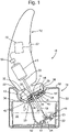
Fig. 1 is a schematic cross-sectional view of an example of a shaving system according to the invention comprising a cleaning device supporting a shaving device, shown in side view, with a shaving unit of the shaving device in a cleaning position; -
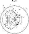
Fig. 2 is a schematic top plan view of the cleaning device shown inFig. 1 (without the shaving device); and -
Fig. 3 is a schematic perspective view of a top portion of the cleaning device shown inFigs. 1 , partially in see-through representation, with a portion of the shaving unit shown in cut-through view through a cutting plane about parallel to a shaving face of the shaving unit. - The drawings show an example of a
shaving system 10 according to the invention which is composed of ashaving device 12 and acleaning device 14 including a supportingstructure 15. Thecleaning device 14 has a pot-shaped housing 22 carrying thesupport structure 15. Thehousing 22 has atop wall 66 in which a generally triangular opening provides access to a receivingpit 28 forming a recess bounding a receiving space in thehousing 22. The shape of the space in the receivingpit 28 corresponds to the shape of ashaving unit 38 of theshaving device 12. Theshaving device 12 can be placed with itsshaving unit 38 in a cleaning position in the receivingpit 28 and supported by the supportingstructure 15 in the cleaning position as shown inFigs. 1 and3 . The main body of theshaving device 12, which in this example is a housing in the shape of a handle, projects upwardly from thecleaning device 14. - A driven
coupling member 30 is provided in a central position of the receivingpit 28 on a slopingbottom wall 29 thereof. When theshaving device 12 is placed with itsshaving unit 38 in the cleaning position in the receivingpit 28 of thecleaning device 14, as shown inFig. 1 , then the drivencoupling member 30 will be coupled with a respectivedriving coupling member 31 provided on theshaving unit 38 of theshaving device 12. Thedriving coupling member 31 is mounted to a driven end of adrive shaft 33 which is coupled to anelectric motor 13 of theshaving device 12. Themotor 13 is also coupled viagear wheels 35 to inner hair-cutting members in the form ofrotatable cutters 34, arranged inside of the outer hair-cutting members, for driving rotation of thecutters 34 during shaving. - Within the
housing 22, acontainer 32 containing cleaningliquid 10 is located. Thecontainer 32 may be provided in the form of a replaceable and disposable or refillable cartridge to facilitate refilling when cleaning liquid is used up. To this end an upper housing part may be removable from a lower housing part or the housing may be provided with a side opening with or without a door, via which the cartridge can be inserted and removed. The container may also be refillable via a filling opening with or without a filling valve. - A
fluid pump unit 48 is located in thecontainer 32. Thefluid pump unit 48 includes adrive shaft 58 coupled to thecoupling 30 and has animpeller 60 attached to a lower end of thedrive shaft 58. Thus, rotating motion of the drivencoupling member 30 can be transferred to theimpeller 60 of thefluid pump 48. Apump chamber 61 extends around the impeller and communicates with aconduit 62. The conduit is in communication with aplenum chamber 63 under thebottom 29 of thepit 28. - When the driven
coupling member 30 is driven by theshaving device 12, theimpeller 60 of thefluid pump 48 is driven via thedrive shaft 58. Thus thepump impeller 60 is rotated so as to draw cleaning liquid through asuction openings 54 and to pass the cleaning liquid throughpump chamber 61 and conduit 62 upwardly into theplenum chamber 63. Instead of by amotor 13 of theshaving device 12, the pump may also be driven in another manner, for instance by a motor of the cleaning unit. - The
shaving unit 38 of theshaving device 12 has threehair cutting units 25. Each hair-cutting unit 25 has an outer hair-cutting member in the form of acutting cap 26 and a respective internal hair-cutting member - in thisexample cutter 34. Eachcutter 34 has a plurality of circumferentially distributed cutting edges arranged to move along an inner surface of therespective cutting cap 26 for cutting off hairs projecting through hair-entry openings 27 in thecutting cap 26 at sharp edges of the hair-entry openings 27. The hair-entry openings 27 are arranged evenly distributed in circumferential sense in a circle in anannular shaving track 37 along which the cutting edges ofinner cutters 34 are rotatable in arotational direction 39. - For delivering cleaning
liquid 10 into the receivingpit 28,injection nozzles 40 communicating with theconduit 62 and thepump unit 48 are arranged and positioned in the receivingpit 28 for directing cleaning liquid delivered from theconduit 62 via theplenum chamber 63 directly to thecutting units 25 of theshaving device 12, when the shaving unit is in the cleaning position. Via the conduit, 62, theplenum chamber 63 and theinjection nozzles 40, thepump unit 48 can pump the cleaningliquid 10 from thereservoir 32 to thereceiving pit 28. - In an alternative embodiment, instead of being distributed to the
injection nozzles 40 via a plenum chamber, the cleaning liquid may be distributed from thepump unit 48 to theinjection nozzles 40 via a plurality of conduits, i.e. via separate conduits for eachrespective injection nozzle 40. Alternatively, the cleaning liquid may be distributed from thepump unit 48 to the injection nozzles by, successively, a main conduit and a plurality of branches of the main conduit, i.e. via separate branches for each respective injection nozzle. - The
injection nozzles 40 are arranged and positioned in the receivingpit 28 for forming a jet of cleaning liquid delivered from theconduit 62 via theplenum chamber 63 directly through one or more of the hair-entry openings 27 only in asingle sector 41 of theannular shaving track 37 extending over at most one half of theannular shaving track 37. - Because the
injection nozzles 40 are arranged and positioned in the receivingpit 28 for each forming a jet of cleaningliquid 10 directly through one or more of the hair-entry openings 27 only in saidsingle sector 41 of theannular shaving track 37 of eachcutting unit 25, cleaning liquid is selectively introduced into a space inside of thecutting cap 26 only through one or more hair-entry openings 27 in saidsingle sector 41 of theannular shaving track 37. This allows the cleaningliquid 10 to flow out of the spaces in the hair-cutting units 25 behind thecutting caps 26 through hair-entry openings 27 in the remaining other sector of each of the annular shaving track 37s. This in turn causes strong currents of cleaning liquid to flow through the spaces in the hair-cutting units 25 behind thecutting caps 26, which is particularly effective for flushing shaving debris away and entrain it out of the space in the hair-cutting units 25 behind thecutting caps 26. As is illustrated inFig. 1 , cleaning liquid entraining shaving debris and other particles and substance flushed out of the hair-cutting units 25 that drips out of the hair-cutting units 25 is drained back into thecontainer 32 via a drainage opening 42 in thebottom 29 of the receivingpit 28. - According to the invention, the sector in which the cleaning liquid is injected in the or each hair-cutting unit is a
single sector 41 extending over at most one half of theannular shaving track 37. This leaves a sufficiently large remaining sector of theannular shaving track 37, via which cleaning liquid can flow out of the or each hair-cutting unit after the cleaning liquid has flowed inside the or each hair-cutting unit over a relatively large distance, which is advantageous for obtaining an powerful flow of cleaning liquid through the or each hair-cutting unit. - For obtaining a powerful flow of cleaning liquid through the or each hair-cutting unit, it is advantageous that, as in the present example, the supporting
structure 15 is arranged for supporting theshaving device 12 such that the or each hair-cutting unit in the cleaning position is oriented with theannular shaving track 37 extending along a plane oriented obliquely relative to a horizontal plane. Thus, theannular shaving track 37 is sloping, which causes cleaning liquid flow inside the or each hair-cutting unit to be driven by gravity as well. - This effect is further enhanced because the
sector 41 via which cleaning liquid is injected extends only outside an angular range of theannular shaving track 37 extending 30° about acentral axis 43 of theannular shaving track 37 at both sides of a median line (midline) 44 of theannular shaving track 37 which extends through alowermost point 45 of theannular shaving track 37. This leaves the hair-entry openings 27 in at least a lowermost sector of 60° of theannular shaving track 37 free for outflow of cleaning liquid. Thus, outflow through the hair-entry openings 27 in a lower portion of thehair cutting unit 25, towards which cleaning liquid tends to flow, is not hindered by inflow in that lower portion of thehair cutting unit 25. - For further enhancing the cleaning and rinsing effect of the cleaning liquid, it is preferred that the
internal cutters 34 are rotated during cleaning of theshaving device 12. In the present example, this is achieved automatically, because thepump 48 is driven by thesame motor 13 as thecutters 34 and both thepump 48 and thecutters 34 are simultaneously coupled to themotor 13. - When the
cutters 34 are being rotated in therotational direction 39 about thecentral axis 43, cleaningliquid 10 is flushed through the cuttingunits 25 of the cleaning device particularly effectively, because in each cuttingunit 25 thesector 41, via which cleaning liquid is injected into the hair-cutting unit via hair-cuttingopenings 27, extends only in an angular range of theannular shaving track 37 extending between 30 and 90° from themedian line 44 of theannular shaving track 37 extending through thelowermost point 45 of theannular shaving track 37, seen in therotational direction 39 of thecutter 34 about thecentral axis 43. A large portion of the injected cleaning liquid is then first entrained uphill by therotating cutter 34 and only leaves the hair-cuttingunit 25 as it has reached lower portions of theannular shaving track 37. For this effect to occur particularly strongly, it is advisable that thesector 41 via which cleaning liquid is injected into the hair-cutting unit via hair-cuttingopenings 27 extends only in an angular range, seen in therotational direction 39, of 40 - 80°, and yet more preferably 50 - 70°, from themedian line 44 of theannular shaving track 37 extending through thelowermost point 45 of theannular shaving track 37. - The main body of the
shaving device 12 is elongate in a direction oblique to the plane in which theannular shaving track 37 extends, such that a portion of theannular shaving track 37 is more remote from a most opposite end of the main body than an opposite portion of theannular shaving track 37. The supportingstructure 15 and theshaving device 12 are arranged such that, when theshaving unit 38 is supported in the cleaning position, the plane in whichannular shaving track 37 extends is obliquely oriented with respect to a horizontal plane, such that said portion of theannular shaving track 37, which is more remote from the most opposite end of the main housing part than said opposite portion of theannular shaving track 37, is positioned at a lower level than said opposite portion of theannular shaving track 37. When theshaving device 12 is supported with theshaving unit 38 in the cleaning position, this causes the direction in which the main body of theshaving device 12 is elongate to be oriented more vertical than if theshaving device 12 would be supported with theannular shaving track 37 extending in a horizontal plane, so theshaving device 12 is better balanced when it is supported with the shaving unit in the cleaning position than if theshaving device 12 would be supported with theannular shaving track 37 extending in a horizontal plane. Moreover, a better view on an operatinginterface 57 of theshaving device 12 is obtained than if theshaving device 12 would be supported with theannular shaving track 37 extending in a horizontal plane. The operatinginterface 57 is located on a side of the main body facing in the same direction as the general direction in which outer surfaces of the shavingunits 25 are tilted relative to a plane perpendicular to the direction in which the main body is elongate. By orienting the direction in which the main body is elongate more vertically, the operatinginterface 57 faces in a direction which is oriented less downwardly or even horizontally or slightly upwardly. - Preferably, the obliqueness of the plane in which the
annular shaving track 37 extends relative to a horizontal plane and the obliqueness of the plane in which theannular shaving track 37 extends relative to the direction in which the main body is elongate are such that the direction in which the main body is elongate is about vertical when theshaving unit 38 is supported in the cleaning position. - As a result of the use of the
injection nozzles 40, a uniform and thorough cleaning of all hair-cuttingunits 25 of the shaving unit is achieved, despite the oblique orientation of the shaving unit in the receivingpit 28. A much less uniform cleaning of all hair-cuttingunits 25 would be achieved when the shaving unit would be placed in an oblique orientation in a receiving space of a prior art cleaning device, wherein the receiving space is filled with the cleaning fluid and wherein the shaving unit is merely immersed as a whole in the cleaning fluid. - When cleaning is completed, it is generally appreciated if the
shaving unit 38 is clean on the outside as well and in particular that no residue of shaving debris flushed out of the hair-cuttingunits 25 is left on the outside of the hair-cuttingunits 25. In the present example, this has been achieved by providing, in addition to theinjection nozzles 40, rinsingnozzles 47 communicating with thepump 48 and theconduit 62 and arranged for rinsing in particular a portion of an outer surface of theshaving unit 38 centrally arranged between the hair-cuttingunits 25. The rinsed outer surface of theshaving unit 38 may also include portions of the outer surfaces of the cutting caps 26 in each of which a lowermost sector of the circle of the hair-entry openings 27 is located, so that shaving debris flushed out of the interiors of the hair-cuttingunits 25 is reliably rinsed away from the outside of theshaving unit 38 as well. - In the present example, the
shaving device 12 has ashaving unit 38 with three hair-cuttingunits 25 and thecleaning unit 14 has threeinjection nozzles 40, each of theinjection nozzles 40 being arranged and positioned in the receivingpit 28 for spraying cleaning liquid delivered from the conduit directly through one or more of the hair-entry openings 27 only in a sector of theannular shaving track 37 of an associated one of the hair-cuttingunits 25. Thus, the cleaning effect is evenly distributed over the hair-cuttingunits 25. - For an evenly distributed cleaning effect, it is further advantageous if, as in the present example, the
shaving device 12 has three of the hair-cuttingunits 25 arranged in a triangular configuration, and the cleaning device has three of theinjection nozzles 40 arranged in a triangular configuration corresponding to the triangular configuration of the hair-cuttingunits 25. - For injecting cleaning liquid into the hair-cutting
units 25 with high power and precision, theinjection nozzles 40 are arranged in or mounted to abottom wall 29 of the receivingpit 28. - The
shaving device 12 has, in the main body to which theshaving unit 38 is mounted, acontrol unit 55 coupled to amotor controller 56 and to the operatinginterface 57. Thecontrol unit 55 is arranged for, in response to a command to start a cleaning cycle inputted through the operatinginterface 57, controlling themotor controller 56 to control themotor 13 for driving of thepump 48 according to a pump program. This may for instance involve a sequence of periods in which themotor 13 is activated, interrupted by pauses for allowing shaving debris to be soaked, to further enhance the cleaning effect of flushing. - While the invention has been illustrated and described in detail in the drawings and foregoing description, such illustration and description are to be considered illustrative or exemplary and not restrictive; the invention is not limited to the disclosed embodiments. Other variations to the disclosed embodiments can be understood and effected by those skilled in the art in practicing the claimed invention, from a study of the drawings, the disclosure, and the appended claims. For instance, the cleaning unit can be arranged for cleaning shaving units with a different number of cutting units, e.g. one, two, four or more cutting units. Also, it is conceivable to position only the shaving unit of the shaving device is in the cleaning position during cleaning, the main housing portion being temporarily dismounted from the shaving unit.
- In the claims, the word "comprising" does not exclude other elements or steps, and the indefinite article "a" or "an" does not exclude a plurality. A single element or other unit may fulfill the functions of several items recited in the claims.
- Any reference signs in the claims should not be construed as limiting the scope.
Claims (12)
- A shaving system (10) comprising a shaving device (12) having a shaving unit (38) and a cleaning device (14) for cleaning the shaving unit, the shaving unit comprising at least one hair-cutting unit (25) having:- an outer hair-cutting member comprising an annular shaving track (37) with a plurality of hair-entry openings (27); and- an inner hair-cutting member rotationally arranged inside of the outer hair-cutting member;the cleaning device (14) comprising:- a supporting structure (15) for supporting the shaving unit (38) in a cleaning position;- a receiving pit (28) for receiving at least an end portion of the shaving unit (38) including the at least one hair-cutting unit (25) when the shaving unit is in the cleaning position supported by the supporting structure (15);- a reservoir (32) for holding a cleaning liquid;- a pump (48) and a conduit for transporting the cleaning liquid from the reservoir (32) to the receiving pit (28); and- at least one liquid-injection nozzle (40) communicating with the conduit and the pump and arranged and positioned in the receiving pit for directing the cleaning liquid delivered from the conduit directly to the hair-cutting unit of the shaving unit when the shaving unit is in the cleaning position;characterized in that the at least one liquid-injection nozzle (40) is arranged and positioned in the receiving pit (28) for generating a jet of the cleaning liquid that, when the shaving unit (38) is supported in the cleaning position, propagates directly through one or more of the hair-entry openings (27) of the shaving unit only in a single sector (41) of the annular shaving track (37) of the outer hair-cutting member (27) extending over at most one half of the annular shaving track (37).
- A shaving system (10) as claimed in claim 1, wherein the supporting structure (15) is arranged for supporting the shaving unit (38) such that, when the shaving unit (38) is supported in the cleaning position, the annular shaving track (37) extends in a plane which is obliquely oriented with respect to a horizontal plane.
- A shaving system (10) as claimed in claim 2, wherein, when the shaving unit (38) is supported in the cleaning position, the sector (41) extends only outside an angular range of the annular shaving track (37) extending 30° about a central axis (43) of the annular shaving track (37) at both sides of a median line (44) of the annular shaving track (37) which extends through a lowermost point (45) of the annular shaving track (37).
- A shaving system (10) as claimed in claim 3, wherein, when the shaving unit (38) is supported in the cleaning position, the sector (41) extends only in an angular range of the annular shaving track (37) extending between 30 and 90° from said median line (44) in a rotational direction (39) of the inner cutting member about the central axis (43).
- A shaving system (10) as claimed in any one of the preceding claims, wherein the liquid-injection nozzle (40) is arranged in or mounted to a bottom wall (29) of the receiving pit (28).
- A shaving system (10) as claimed in any one of the preceding claims, wherein the shaving unit (38) comprises at least two of said hair-cutting units (25), and wherein the cleaning device comprises at least two of said liquid-injection nozzles (40), each of said liquid-injection nozzles (40) being arranged and positioned in the receiving pit (28) for generating a jet of the cleaning liquid that, when the shaving unit is supported in the cleaning position, propagates directly through one or more of the hair-entry openings (27) only in a single sector (41) of the annular shaving track (37) of the outer hair-cutting member of a respective one of the hair-cutting units (25) extending over at most one half of the annular shaving track (37).
- A shaving system (10) as claimed in claim 6, wherein the shaving unit (38) comprises three of said hair-cutting units (25) arranged in a tri-angular configuration, and wherein the cleaning device (14) comprises three of said liquid-injection nozzles (40) arranged in a triangular configuration corresponding to the triangular configuration of the hair-cutting units (25).
- A shaving system (10) as claimed in claim 6 or 7, further comprising at least one rinsing nozzle (47) communicating with the pump (48) and the conduit (62) and arranged for rinsing a portion of an outer surface of the shaving unit centrally arranged between the hair-cutting units.
- A shaving system (10) as claimed in claim 1, wherein:- the shaving device (12) has a main body to which the shaving unit (38) is mounted;- the main body is elongate in a direction oblique to a plane in which the annular shaving track (37) extends, such that a portion of the annular shaving track (37) is more remote from a most opposite end of the main body than an opposite portion of the annular shaving track (37);- the supporting structure (15) and the shaving device (12) are configured such that, when the shaving unit (38) is supported in the cleaning position, the plane in which the annular shaving track (37) extends is obliquely oriented with respect to a horizontal plane, such that said portion of the annular shaving track (37), which is more remote from the most opposite end of the main body than said opposite portion of the annular shaving track (37), is positioned at a lower level than said opposite portion of the annular shaving track (37).
- A shaving system (10) as claimed in claim 9, wherein the main body of the shaving device (12) accommodates a motor, and wherein the supporting structure of the cleaning device is adapted to support the main body in the cleaning position of the shaving unit.
- A shaving system (10) as claimed in claim 10, wherein the main body of the shaving device (12) further accommodates a control unit (55) configured and arranged for controlling the driving of the pump (48) according to a pump program.
- A shaving system (10) as claimed in claim 11, wherein the main body of the shaving device (12) comprises a user interface (57) coupled to the control unit (55) by means of which a user of the shaving system (10) can activate the pump program.
Applications Claiming Priority (2)
| Application Number | Priority Date | Filing Date | Title |
|---|---|---|---|
| EP19189767.7A EP3771529A1 (en) | 2019-08-02 | 2019-08-02 | Cleaning device for cleaning a shaving device and shaving system including such a cleaning device |
| PCT/EP2020/071213 WO2021023570A1 (en) | 2019-08-02 | 2020-07-28 | Cleaning device for cleaning a shaving device and shaving system including such a cleaning device |
Publications (2)
| Publication Number | Publication Date |
|---|---|
| EP3924153A1 EP3924153A1 (en) | 2021-12-22 |
| EP3924153B1 true EP3924153B1 (en) | 2022-05-25 |
Family
ID=67539350
Family Applications (2)
| Application Number | Title | Priority Date | Filing Date |
|---|---|---|---|
| EP19189767.7A Withdrawn EP3771529A1 (en) | 2019-08-02 | 2019-08-02 | Cleaning device for cleaning a shaving device and shaving system including such a cleaning device |
| EP20743721.1A Active EP3924153B1 (en) | 2019-08-02 | 2020-07-28 | Shaving system including a cleaning device for cleaning a shaving device |
Family Applications Before (1)
| Application Number | Title | Priority Date | Filing Date |
|---|---|---|---|
| EP19189767.7A Withdrawn EP3771529A1 (en) | 2019-08-02 | 2019-08-02 | Cleaning device for cleaning a shaving device and shaving system including such a cleaning device |
Country Status (8)
| Country | Link |
|---|---|
| US (1) | US12543837B2 (en) |
| EP (2) | EP3771529A1 (en) |
| JP (1) | JP7151019B2 (en) |
| CN (2) | CN212978413U (en) |
| ES (1) | ES2923631T3 (en) |
| PL (1) | PL3924153T3 (en) |
| SG (1) | SG11202110404YA (en) |
| WO (1) | WO2021023570A1 (en) |
Cited By (1)
| Publication number | Priority date | Publication date | Assignee | Title |
|---|---|---|---|---|
| WO2025040482A1 (en) | 2023-08-23 | 2025-02-27 | Koninklijke Philips N.V. | Method for determining a quantitative condition of a cleaning liquid in a cleaning device for a personal care device |
Families Citing this family (8)
| Publication number | Priority date | Publication date | Assignee | Title |
|---|---|---|---|---|
| EP3771529A1 (en) * | 2019-08-02 | 2021-02-03 | Koninklijke Philips N.V. | Cleaning device for cleaning a shaving device and shaving system including such a cleaning device |
| USD1010324S1 (en) * | 2019-09-03 | 2024-01-09 | Koninklijke Philips N.V. | Cleansing brush for shaver |
| EP3815569A1 (en) * | 2019-10-29 | 2021-05-05 | Koninklijke Philips N.V. | Shaving system with shaving unit and cleaning device |
| CN113352360A (en) * | 2021-04-28 | 2021-09-07 | 上海第二工业大学 | Linear cutting hair clipper |
| EP4578609A1 (en) * | 2023-12-29 | 2025-07-02 | Braun GmbH | Reinforced shaver cleaning station cartridges and methods for manufacturing the same |
| EP4578610A1 (en) * | 2023-12-29 | 2025-07-02 | Braun GmbH | Shaver cleaning station cartridges and methods for manufacturing the same |
| EP4670934A1 (en) * | 2024-06-28 | 2025-12-31 | Braun GmbH | ARRANGEMENT OF A CLEANING STATION FOR RAZORS |
| DE102024123651A1 (en) * | 2024-08-19 | 2026-02-19 | Anthony Yankah Stölting | Cleaning device for hair clippers and method for cleaning a hair clipper |
Family Cites Families (54)
| Publication number | Priority date | Publication date | Assignee | Title |
|---|---|---|---|---|
| US3172416A (en) * | 1963-06-28 | 1965-03-09 | Herbert H Simmons | Cleaning device for electric razors |
| US3365267A (en) * | 1963-09-12 | 1968-01-23 | Sterilmaster Inc | Sterilizer unit for barber tools |
| US4054963A (en) * | 1976-02-23 | 1977-10-25 | Taylor Clarence R | Electric shaver head cleaning device |
| US4838949A (en) * | 1987-07-20 | 1989-06-13 | Felipe Dugrot | Shaving razor cleaner |
| US4910869A (en) * | 1987-11-24 | 1990-03-27 | U.S. Philips Corp. | Electric shaving apparatus |
| US5365958A (en) * | 1993-04-07 | 1994-11-22 | Stuhlmacher Ii Glen | Razor cleaning device |
| DE4402236C2 (en) * | 1994-01-26 | 1996-09-26 | Braun Ag | Method for operating a cleaning device for the shaving head of a dry shaving apparatus |
| DE19705977C1 (en) * | 1997-02-17 | 1998-03-05 | Braun Ag | Cleaner for cutting head of dry razor |
| US6009622A (en) * | 1998-02-06 | 2000-01-04 | Liedblad; Thomas F. | Razor cleaning device |
| WO2000038890A1 (en) * | 1998-12-29 | 2000-07-06 | Koninklijke Philips Electronics N.V. | Shaving apparatus |
| DE10209326C1 (en) * | 2002-03-02 | 2003-06-18 | Braun Gmbh | Cleaning device for cutting head of dry razor has holder part for cutting head that can be filled with cleaning liquid up to defined level for cleaning and can be emptied via regulated outlet |
| DE10222716A1 (en) * | 2002-05-23 | 2003-12-11 | Braun Gmbh | Cleaning device for the shaving head of a dry shaver |
| US20050189004A1 (en) * | 2002-09-21 | 2005-09-01 | Jurgen Hoser | Cleaning device and container for a shaving apparatus |
| WO2004062420A2 (en) * | 2003-01-07 | 2004-07-29 | Remington Products Company, L.L.C | Method and apparatus for cleaning the cutting system of an electric shaver |
| JP4036102B2 (en) * | 2003-01-21 | 2008-01-23 | 松下電工株式会社 | Depilation device cleaning system |
| ATE390864T1 (en) * | 2003-01-21 | 2008-04-15 | Matsushita Electric Works Ltd | CLEANING DEVICE FOR A HAIR REMOVING DEVICE |
| DE10315455A1 (en) * | 2003-04-04 | 2004-11-11 | Braun Gmbh | Cleaning device for a shaver |
| DE10315453A1 (en) * | 2003-04-04 | 2004-11-04 | Braun Gmbh | Cleaning device for a shaver |
| DE10316935A1 (en) * | 2003-04-12 | 2004-11-04 | Braun Gmbh | System of a small electrical device and an associated electrical additional device |
| DE10332385A1 (en) * | 2003-07-17 | 2005-02-17 | Braun Gmbh | Razor cleaning device, comprising particularly coarse filter for avoidance of blocking by fine particles |
| US7625451B2 (en) * | 2004-01-05 | 2009-12-01 | Rovcal, Inc. | Method and apparatus for cleaning the cutting system of an electric shaver |
| DE102004032518A1 (en) * | 2004-07-06 | 2006-01-26 | Braun Gmbh | Cleaning device for the shaving head of a dry shaver |
| KR101190216B1 (en) * | 2004-08-19 | 2012-10-16 | 코닌클리케 필립스 일렉트로닉스 엔.브이. | A personal care system comprising an electrical shaver and a cleaning device |
| US20060042036A1 (en) * | 2004-08-31 | 2006-03-02 | Rovcal, Inc. | Electric shaver and cleaning system therefor |
| CN100575010C (en) | 2004-12-20 | 2009-12-30 | 皇家飞利浦电子股份有限公司 | Apparatus for supplying shaving aids to electric shavers or components of electric shavers |
| US20060283487A1 (en) * | 2005-06-15 | 2006-12-21 | Richard Grabowski | Razor cleaning device |
| CN101242755B (en) * | 2005-08-17 | 2010-12-08 | 皇家飞利浦电子股份有限公司 | Apparatus and method for cleaning electric hair cutting equipment and kits comprising such an apparatus |
| JP4375316B2 (en) * | 2005-09-27 | 2009-12-02 | パナソニック電工株式会社 | Agent supply device |
| JP2007252675A (en) * | 2006-03-24 | 2007-10-04 | Matsushita Electric Works Ltd | Agent feeder |
| JP4438774B2 (en) * | 2006-07-14 | 2010-03-24 | パナソニック電工株式会社 | Shaver cleaning device and shaver system |
| JP4165582B2 (en) * | 2006-07-14 | 2008-10-15 | 松下電工株式会社 | Holding structure of electric razor and charger |
| JP2008061880A (en) * | 2006-09-08 | 2008-03-21 | Izumi Products Co | Cleaner for electric shaver |
| JP5011464B2 (en) | 2006-10-17 | 2012-08-29 | 日立マクセル株式会社 | Electric razor cleaning equipment |
| WO2008075243A1 (en) * | 2006-12-15 | 2008-06-26 | Koninklijke Philips Electronics N.V. | Unit for cleaning an interior space of a shaving head of a shaver |
| JP4400646B2 (en) * | 2007-05-14 | 2010-01-20 | パナソニック電工株式会社 | Hair dryer |
| JP2010057837A (en) * | 2008-09-05 | 2010-03-18 | Sanyo Electric Co Ltd | Electric shaver washer |
| JP4798227B2 (en) * | 2009-01-15 | 2011-10-19 | パナソニック電工株式会社 | Cleaning device |
| US8177918B2 (en) * | 2009-03-24 | 2012-05-15 | Rovcal, LLC | Cleaning system for an electric shaver |
| US8939161B2 (en) * | 2009-03-24 | 2015-01-27 | Spectrum Brands, Inc. | Cleaning system for an electric shaver |
| JP5750580B2 (en) * | 2011-02-28 | 2015-07-22 | パナソニックIpマネジメント株式会社 | Holding device for small electrical equipment |
| EP2543274B1 (en) * | 2011-07-06 | 2017-08-23 | Braun GmbH | Electrically operated cleaning device for razor |
| JP2014230666A (en) * | 2013-05-29 | 2014-12-11 | パナソニック株式会社 | Hair remover washing device |
| RU2649949C2 (en) * | 2013-09-30 | 2018-04-05 | Конинклейке Филипс Н.В. | System of cleaning the shaving unit |
| US9914154B2 (en) * | 2014-06-24 | 2018-03-13 | Frederick Firouz Rabie | Multi-blade razor cartridge cleaner |
| JP2019072097A (en) * | 2017-10-13 | 2019-05-16 | 株式会社泉精器製作所 | Electric shaver washer and electric shaver washing system |
| EP3666114A1 (en) * | 2018-12-13 | 2020-06-17 | Koninklijke Philips N.V. | Shaving system with shaving device and cleaning device |
| EP3771528A1 (en) * | 2019-07-30 | 2021-02-03 | Koninklijke Philips N.V. | Shaving device, shaving system with the shaving device and a cleaning device, and a cleaning method |
| EP3771529A1 (en) * | 2019-08-02 | 2021-02-03 | Koninklijke Philips N.V. | Cleaning device for cleaning a shaving device and shaving system including such a cleaning device |
| EP3815569A1 (en) * | 2019-10-29 | 2021-05-05 | Koninklijke Philips N.V. | Shaving system with shaving unit and cleaning device |
| US20210235840A1 (en) * | 2020-02-04 | 2021-08-05 | Moises Kattan | Razor Head Cleaning Device |
| US11697138B2 (en) * | 2020-03-24 | 2023-07-11 | Rheem Manufacturing Company | Cleaning devices for personal care tools |
| US11678731B1 (en) * | 2020-04-20 | 2023-06-20 | Preston Leon Howard | Razor cleaning device for sink, bath, and shower |
| US12520923B2 (en) * | 2021-09-27 | 2026-01-13 | Johansen Wilson | Hair clipper cleaning device |
| WO2024036267A1 (en) * | 2022-08-11 | 2024-02-15 | BAM Concepts, LLC | Blade treatment assembly |
-
2019
- 2019-08-02 EP EP19189767.7A patent/EP3771529A1/en not_active Withdrawn
-
2020
- 2020-07-28 PL PL20743721.1T patent/PL3924153T3/en unknown
- 2020-07-28 EP EP20743721.1A patent/EP3924153B1/en active Active
- 2020-07-28 ES ES20743721T patent/ES2923631T3/en active Active
- 2020-07-28 SG SG11202110404YA patent/SG11202110404YA/en unknown
- 2020-07-28 US US17/600,165 patent/US12543837B2/en active Active
- 2020-07-28 JP JP2022506012A patent/JP7151019B2/en active Active
- 2020-07-28 WO PCT/EP2020/071213 patent/WO2021023570A1/en not_active Ceased
- 2020-07-30 CN CN202021542282.5U patent/CN212978413U/en not_active Withdrawn - After Issue
- 2020-07-30 CN CN202010748863.2A patent/CN112297065B/en active Active
Cited By (1)
| Publication number | Priority date | Publication date | Assignee | Title |
|---|---|---|---|---|
| WO2025040482A1 (en) | 2023-08-23 | 2025-02-27 | Koninklijke Philips N.V. | Method for determining a quantitative condition of a cleaning liquid in a cleaning device for a personal care device |
Also Published As
| Publication number | Publication date |
|---|---|
| JP2022535153A (en) | 2022-08-04 |
| KR20220042298A (en) | 2022-04-05 |
| CN112297065B (en) | 2024-12-03 |
| JP7151019B2 (en) | 2022-10-11 |
| CN212978413U (en) | 2021-04-16 |
| EP3771529A1 (en) | 2021-02-03 |
| US12543837B2 (en) | 2026-02-10 |
| US20220202161A1 (en) | 2022-06-30 |
| EP3924153A1 (en) | 2021-12-22 |
| SG11202110404YA (en) | 2021-10-28 |
| CN112297065A (en) | 2021-02-02 |
| PL3924153T3 (en) | 2022-09-26 |
| WO2021023570A1 (en) | 2021-02-11 |
| ES2923631T3 (en) | 2022-09-29 |
Similar Documents
| Publication | Publication Date | Title |
|---|---|---|
| US12543837B2 (en) | Shaving system having a shaving device and a cleaning device | |
| JP4237136B2 (en) | Dry shaving equipment shaving head cleaning equipment | |
| EP1310204B1 (en) | Scrubbing machine | |
| TWI302451B (en) | Dishwasher | |
| US8601631B1 (en) | Cleaning brush assembly | |
| US20150143643A1 (en) | Device for cleaning a submerged surface with a propelled water jet | |
| CN220360385U (en) | Cleaning heads and utensils for utensils | |
| CN220360380U (en) | Cleaning head for an appliance and appliance | |
| CN220360378U (en) | Cleaning head for an appliance and appliance | |
| JP5249759B2 (en) | Apparatus and method for cleaning an electric hair cutter and kit having such apparatus | |
| HK40057593B (en) | Shaving system including a cleaning device for cleaning a shaving device | |
| HK40057593A (en) | Shaving system including a cleaning device for cleaning a shaving device | |
| KR102959947B1 (en) | A cleaning device for cleaning a shaving device and a shaving system including such a cleaning device | |
| JP2012019825A (en) | Face washing device | |
| RU2787262C1 (en) | Cleaning apparatus for cleaning a shaving apparatus and shaving system containing such a cleaning apparatus | |
| KR102366385B1 (en) | Face washing device comprising oxygen supply | |
| CN100572001C (en) | agent supply device | |
| JP2003010804A (en) | Cleaning equipment | |
| JP5011464B2 (en) | Electric razor cleaning equipment | |
| CN116615129A (en) | Improved self-cleaning centrifugal coffee brewing machine | |
| JP3993808B2 (en) | Drying device and sanitary washing device provided with the same | |
| KR102223540B1 (en) | Portable eyewashing device | |
| JP2019171233A (en) | Bubble discharge device | |
| JPH0592400A (en) | Method of removing object sticking to outer surface | |
| JPH08187471A (en) | Washing apparatus |
Legal Events
| Date | Code | Title | Description |
|---|---|---|---|
| STAA | Information on the status of an ep patent application or granted ep patent |
Free format text: STATUS: UNKNOWN |
|
| STAA | Information on the status of an ep patent application or granted ep patent |
Free format text: STATUS: THE INTERNATIONAL PUBLICATION HAS BEEN MADE |
|
| PUAI | Public reference made under article 153(3) epc to a published international application that has entered the european phase |
Free format text: ORIGINAL CODE: 0009012 |
|
| STAA | Information on the status of an ep patent application or granted ep patent |
Free format text: STATUS: REQUEST FOR EXAMINATION WAS MADE |
|
| GRAP | Despatch of communication of intention to grant a patent |
Free format text: ORIGINAL CODE: EPIDOSNIGR1 |
|
| STAA | Information on the status of an ep patent application or granted ep patent |
Free format text: STATUS: GRANT OF PATENT IS INTENDED |
|
| 17P | Request for examination filed |
Effective date: 20210915 |
|
| AK | Designated contracting states |
Kind code of ref document: A1 Designated state(s): AL AT BE BG CH CY CZ DE DK EE ES FI FR GB GR HR HU IE IS IT LI LT LU LV MC MK MT NL NO PL PT RO RS SE SI SK SM TR |
|
| INTG | Intention to grant announced |
Effective date: 20211217 |
|
| GRAS | Grant fee paid |
Free format text: ORIGINAL CODE: EPIDOSNIGR3 |
|
| REG | Reference to a national code |
Ref country code: HK Ref legal event code: DE Ref document number: 40057593 Country of ref document: HK |
|
| GRAA | (expected) grant |
Free format text: ORIGINAL CODE: 0009210 |
|
| STAA | Information on the status of an ep patent application or granted ep patent |
Free format text: STATUS: THE PATENT HAS BEEN GRANTED |
|
| DAV | Request for validation of the european patent (deleted) | ||
| DAX | Request for extension of the european patent (deleted) | ||
| AK | Designated contracting states |
Kind code of ref document: B1 Designated state(s): AL AT BE BG CH CY CZ DE DK EE ES FI FR GB GR HR HU IE IS IT LI LT LU LV MC MK MT NL NO PL PT RO RS SE SI SK SM TR |
|
| REG | Reference to a national code |
Ref country code: GB Ref legal event code: FG4D |
|
| REG | Reference to a national code |
Ref country code: CH Ref legal event code: EP |
|
| REG | Reference to a national code |
Ref country code: DE Ref legal event code: R096 Ref document number: 602020003298 Country of ref document: DE |
|
| REG | Reference to a national code |
Ref country code: AT Ref legal event code: REF Ref document number: 1494079 Country of ref document: AT Kind code of ref document: T Effective date: 20220615 |
|
| REG | Reference to a national code |
Ref country code: IE Ref legal event code: FG4D |
|
| REG | Reference to a national code |
Ref country code: NL Ref legal event code: FP |
|
| REG | Reference to a national code |
Ref country code: LT Ref legal event code: MG9D |
|
| REG | Reference to a national code |
Ref country code: SE Ref legal event code: TRGR |
|
| REG | Reference to a national code |
Ref country code: ES Ref legal event code: FG2A Ref document number: 2923631 Country of ref document: ES Kind code of ref document: T3 Effective date: 20220929 |
|
| REG | Reference to a national code |
Ref country code: AT Ref legal event code: MK05 Ref document number: 1494079 Country of ref document: AT Kind code of ref document: T Effective date: 20220525 |
|
| PG25 | Lapsed in a contracting state [announced via postgrant information from national office to epo] |
Ref country code: PT Free format text: LAPSE BECAUSE OF FAILURE TO SUBMIT A TRANSLATION OF THE DESCRIPTION OR TO PAY THE FEE WITHIN THE PRESCRIBED TIME-LIMIT Effective date: 20220926 Ref country code: NO Free format text: LAPSE BECAUSE OF FAILURE TO SUBMIT A TRANSLATION OF THE DESCRIPTION OR TO PAY THE FEE WITHIN THE PRESCRIBED TIME-LIMIT Effective date: 20220825 Ref country code: LT Free format text: LAPSE BECAUSE OF FAILURE TO SUBMIT A TRANSLATION OF THE DESCRIPTION OR TO PAY THE FEE WITHIN THE PRESCRIBED TIME-LIMIT Effective date: 20220525 Ref country code: HR Free format text: LAPSE BECAUSE OF FAILURE TO SUBMIT A TRANSLATION OF THE DESCRIPTION OR TO PAY THE FEE WITHIN THE PRESCRIBED TIME-LIMIT Effective date: 20220525 Ref country code: GR Free format text: LAPSE BECAUSE OF FAILURE TO SUBMIT A TRANSLATION OF THE DESCRIPTION OR TO PAY THE FEE WITHIN THE PRESCRIBED TIME-LIMIT Effective date: 20220826 Ref country code: FI Free format text: LAPSE BECAUSE OF FAILURE TO SUBMIT A TRANSLATION OF THE DESCRIPTION OR TO PAY THE FEE WITHIN THE PRESCRIBED TIME-LIMIT Effective date: 20220525 Ref country code: BG Free format text: LAPSE BECAUSE OF FAILURE TO SUBMIT A TRANSLATION OF THE DESCRIPTION OR TO PAY THE FEE WITHIN THE PRESCRIBED TIME-LIMIT Effective date: 20220825 Ref country code: AT Free format text: LAPSE BECAUSE OF FAILURE TO SUBMIT A TRANSLATION OF THE DESCRIPTION OR TO PAY THE FEE WITHIN THE PRESCRIBED TIME-LIMIT Effective date: 20220525 |
|
| PG25 | Lapsed in a contracting state [announced via postgrant information from national office to epo] |
Ref country code: RS Free format text: LAPSE BECAUSE OF FAILURE TO SUBMIT A TRANSLATION OF THE DESCRIPTION OR TO PAY THE FEE WITHIN THE PRESCRIBED TIME-LIMIT Effective date: 20220525 Ref country code: LV Free format text: LAPSE BECAUSE OF FAILURE TO SUBMIT A TRANSLATION OF THE DESCRIPTION OR TO PAY THE FEE WITHIN THE PRESCRIBED TIME-LIMIT Effective date: 20220525 Ref country code: IS Free format text: LAPSE BECAUSE OF FAILURE TO SUBMIT A TRANSLATION OF THE DESCRIPTION OR TO PAY THE FEE WITHIN THE PRESCRIBED TIME-LIMIT Effective date: 20220925 |
|
| PG25 | Lapsed in a contracting state [announced via postgrant information from national office to epo] |
Ref country code: SM Free format text: LAPSE BECAUSE OF FAILURE TO SUBMIT A TRANSLATION OF THE DESCRIPTION OR TO PAY THE FEE WITHIN THE PRESCRIBED TIME-LIMIT Effective date: 20220525 Ref country code: SK Free format text: LAPSE BECAUSE OF FAILURE TO SUBMIT A TRANSLATION OF THE DESCRIPTION OR TO PAY THE FEE WITHIN THE PRESCRIBED TIME-LIMIT Effective date: 20220525 Ref country code: RO Free format text: LAPSE BECAUSE OF FAILURE TO SUBMIT A TRANSLATION OF THE DESCRIPTION OR TO PAY THE FEE WITHIN THE PRESCRIBED TIME-LIMIT Effective date: 20220525 Ref country code: EE Free format text: LAPSE BECAUSE OF FAILURE TO SUBMIT A TRANSLATION OF THE DESCRIPTION OR TO PAY THE FEE WITHIN THE PRESCRIBED TIME-LIMIT Effective date: 20220525 Ref country code: DK Free format text: LAPSE BECAUSE OF FAILURE TO SUBMIT A TRANSLATION OF THE DESCRIPTION OR TO PAY THE FEE WITHIN THE PRESCRIBED TIME-LIMIT Effective date: 20220525 Ref country code: CZ Free format text: LAPSE BECAUSE OF FAILURE TO SUBMIT A TRANSLATION OF THE DESCRIPTION OR TO PAY THE FEE WITHIN THE PRESCRIBED TIME-LIMIT Effective date: 20220525 |
|
| PG25 | Lapsed in a contracting state [announced via postgrant information from national office to epo] |
Ref country code: MC Free format text: LAPSE BECAUSE OF FAILURE TO SUBMIT A TRANSLATION OF THE DESCRIPTION OR TO PAY THE FEE WITHIN THE PRESCRIBED TIME-LIMIT Effective date: 20220525 |
|
| REG | Reference to a national code |
Ref country code: DE Ref legal event code: R097 Ref document number: 602020003298 Country of ref document: DE |
|
| REG | Reference to a national code |
Ref country code: BE Ref legal event code: MM Effective date: 20220731 |
|
| PG25 | Lapsed in a contracting state [announced via postgrant information from national office to epo] |
Ref country code: AL Free format text: LAPSE BECAUSE OF FAILURE TO SUBMIT A TRANSLATION OF THE DESCRIPTION OR TO PAY THE FEE WITHIN THE PRESCRIBED TIME-LIMIT Effective date: 20220525 |
|
| PLBE | No opposition filed within time limit |
Free format text: ORIGINAL CODE: 0009261 |
|
| STAA | Information on the status of an ep patent application or granted ep patent |
Free format text: STATUS: NO OPPOSITION FILED WITHIN TIME LIMIT |
|
| PG25 | Lapsed in a contracting state [announced via postgrant information from national office to epo] |
Ref country code: LU Free format text: LAPSE BECAUSE OF NON-PAYMENT OF DUE FEES Effective date: 20220728 |
|
| 26N | No opposition filed |
Effective date: 20230228 |
|
| PG25 | Lapsed in a contracting state [announced via postgrant information from national office to epo] |
Ref country code: BE Free format text: LAPSE BECAUSE OF NON-PAYMENT OF DUE FEES Effective date: 20220731 |
|
| PG25 | Lapsed in a contracting state [announced via postgrant information from national office to epo] |
Ref country code: IE Free format text: LAPSE BECAUSE OF NON-PAYMENT OF DUE FEES Effective date: 20220728 |
|
| PGFP | Annual fee paid to national office [announced via postgrant information from national office to epo] |
Ref country code: IT Payment date: 20230731 Year of fee payment: 4 |
|
| PGFP | Annual fee paid to national office [announced via postgrant information from national office to epo] |
Ref country code: SE Payment date: 20230726 Year of fee payment: 4 |
|
| REG | Reference to a national code |
Ref country code: CH Ref legal event code: PL |
|
| PG25 | Lapsed in a contracting state [announced via postgrant information from national office to epo] |
Ref country code: MK Free format text: LAPSE BECAUSE OF FAILURE TO SUBMIT A TRANSLATION OF THE DESCRIPTION OR TO PAY THE FEE WITHIN THE PRESCRIBED TIME-LIMIT Effective date: 20220525 Ref country code: CY Free format text: LAPSE BECAUSE OF FAILURE TO SUBMIT A TRANSLATION OF THE DESCRIPTION OR TO PAY THE FEE WITHIN THE PRESCRIBED TIME-LIMIT Effective date: 20220525 Ref country code: CH Free format text: LAPSE BECAUSE OF NON-PAYMENT OF DUE FEES Effective date: 20230731 |
|
| PG25 | Lapsed in a contracting state [announced via postgrant information from national office to epo] |
Ref country code: HU Free format text: LAPSE BECAUSE OF FAILURE TO SUBMIT A TRANSLATION OF THE DESCRIPTION OR TO PAY THE FEE WITHIN THE PRESCRIBED TIME-LIMIT; INVALID AB INITIO Effective date: 20200728 |
|
| PG25 | Lapsed in a contracting state [announced via postgrant information from national office to epo] |
Ref country code: TR Free format text: LAPSE BECAUSE OF FAILURE TO SUBMIT A TRANSLATION OF THE DESCRIPTION OR TO PAY THE FEE WITHIN THE PRESCRIBED TIME-LIMIT Effective date: 20220525 |
|
| PG25 | Lapsed in a contracting state [announced via postgrant information from national office to epo] |
Ref country code: MT Free format text: LAPSE BECAUSE OF FAILURE TO SUBMIT A TRANSLATION OF THE DESCRIPTION OR TO PAY THE FEE WITHIN THE PRESCRIBED TIME-LIMIT Effective date: 20220525 |
|
| PG25 | Lapsed in a contracting state [announced via postgrant information from national office to epo] |
Ref country code: BG Free format text: LAPSE BECAUSE OF FAILURE TO SUBMIT A TRANSLATION OF THE DESCRIPTION OR TO PAY THE FEE WITHIN THE PRESCRIBED TIME-LIMIT Effective date: 20220525 |
|
| PG25 | Lapsed in a contracting state [announced via postgrant information from national office to epo] |
Ref country code: BG Free format text: LAPSE BECAUSE OF FAILURE TO SUBMIT A TRANSLATION OF THE DESCRIPTION OR TO PAY THE FEE WITHIN THE PRESCRIBED TIME-LIMIT Effective date: 20220525 |
|
| REG | Reference to a national code |
Ref country code: SE Ref legal event code: EUG |
|
| PG25 | Lapsed in a contracting state [announced via postgrant information from national office to epo] |
Ref country code: IT Free format text: LAPSE BECAUSE OF NON-PAYMENT OF DUE FEES Effective date: 20240728 |
|
| PGFP | Annual fee paid to national office [announced via postgrant information from national office to epo] |
Ref country code: NL Payment date: 20250724 Year of fee payment: 6 |
|
| PGFP | Annual fee paid to national office [announced via postgrant information from national office to epo] |
Ref country code: ES Payment date: 20250811 Year of fee payment: 6 |
|
| PGFP | Annual fee paid to national office [announced via postgrant information from national office to epo] |
Ref country code: DE Payment date: 20250728 Year of fee payment: 6 |
|
| PG25 | Lapsed in a contracting state [announced via postgrant information from national office to epo] |
Ref country code: SE Free format text: LAPSE BECAUSE OF NON-PAYMENT OF DUE FEES Effective date: 20240729 |
|
| PGFP | Annual fee paid to national office [announced via postgrant information from national office to epo] |
Ref country code: PL Payment date: 20250717 Year of fee payment: 6 |
|
| PGFP | Annual fee paid to national office [announced via postgrant information from national office to epo] |
Ref country code: GB Payment date: 20250722 Year of fee payment: 6 |
|
| PGFP | Annual fee paid to national office [announced via postgrant information from national office to epo] |
Ref country code: FR Payment date: 20250725 Year of fee payment: 6 |
|
| PG25 | Lapsed in a contracting state [announced via postgrant information from national office to epo] |
Ref country code: SI Free format text: LAPSE BECAUSE OF FAILURE TO SUBMIT A TRANSLATION OF THE DESCRIPTION OR TO PAY THE FEE WITHIN THE PRESCRIBED TIME-LIMIT Effective date: 20220525 |