EP3923378A1 - Method for manufacturing nonaqueous electrolyte secondary battery and nonaqueous electrolyte secondary battery - Google Patents
Method for manufacturing nonaqueous electrolyte secondary battery and nonaqueous electrolyte secondary battery Download PDFInfo
- Publication number
- EP3923378A1 EP3923378A1 EP19914592.1A EP19914592A EP3923378A1 EP 3923378 A1 EP3923378 A1 EP 3923378A1 EP 19914592 A EP19914592 A EP 19914592A EP 3923378 A1 EP3923378 A1 EP 3923378A1
- Authority
- EP
- European Patent Office
- Prior art keywords
- positive electrode
- positive
- electrode plate
- secondary battery
- electrolyte secondary
- Prior art date
- Legal status (The legal status is an assumption and is not a legal conclusion. Google has not performed a legal analysis and makes no representation as to the accuracy of the status listed.)
- Pending
Links
- 239000011255 nonaqueous electrolyte Substances 0.000 title claims abstract description 34
- 238000000034 method Methods 0.000 title claims description 12
- 238000004519 manufacturing process Methods 0.000 title claims description 9
- 238000012856 packing Methods 0.000 claims abstract description 12
- 229910052744 lithium Inorganic materials 0.000 claims abstract description 11
- 239000002905 metal composite material Substances 0.000 claims abstract description 11
- 229910052782 aluminium Inorganic materials 0.000 claims abstract description 10
- 229910052748 manganese Inorganic materials 0.000 claims abstract description 8
- 229910052759 nickel Inorganic materials 0.000 claims abstract description 8
- 238000004804 winding Methods 0.000 claims description 59
- 239000000203 mixture Substances 0.000 claims description 47
- 238000003825 pressing Methods 0.000 claims description 12
- 230000002093 peripheral effect Effects 0.000 claims description 11
- 230000015572 biosynthetic process Effects 0.000 claims description 7
- 239000000463 material Substances 0.000 abstract description 10
- 239000010410 layer Substances 0.000 description 39
- OKTJSMMVPCPJKN-UHFFFAOYSA-N Carbon Chemical compound [C] OKTJSMMVPCPJKN-UHFFFAOYSA-N 0.000 description 21
- 238000007789 sealing Methods 0.000 description 19
- 230000000052 comparative effect Effects 0.000 description 18
- 239000007774 positive electrode material Substances 0.000 description 13
- 239000011230 binding agent Substances 0.000 description 12
- 239000002245 particle Substances 0.000 description 12
- 229910052751 metal Inorganic materials 0.000 description 10
- 239000002184 metal Substances 0.000 description 10
- 229910052799 carbon Inorganic materials 0.000 description 9
- 238000005336 cracking Methods 0.000 description 9
- 239000007773 negative electrode material Substances 0.000 description 9
- -1 polyethylene Polymers 0.000 description 9
- 239000002002 slurry Substances 0.000 description 9
- 229920005989 resin Polymers 0.000 description 8
- 239000011347 resin Substances 0.000 description 8
- 239000003575 carbonaceous material Substances 0.000 description 6
- 239000003792 electrolyte Substances 0.000 description 6
- 239000002033 PVDF binder Substances 0.000 description 5
- 239000008151 electrolyte solution Substances 0.000 description 5
- 238000011156 evaluation Methods 0.000 description 5
- 229910002804 graphite Inorganic materials 0.000 description 5
- 239000010439 graphite Substances 0.000 description 5
- 229920002981 polyvinylidene fluoride Polymers 0.000 description 5
- 150000003839 salts Chemical class 0.000 description 5
- SECXISVLQFMRJM-UHFFFAOYSA-N N-Methylpyrrolidone Chemical compound CN1CCCC1=O SECXISVLQFMRJM-UHFFFAOYSA-N 0.000 description 4
- 239000004743 Polypropylene Substances 0.000 description 4
- 239000003125 aqueous solvent Substances 0.000 description 4
- 239000006229 carbon black Substances 0.000 description 4
- 239000006258 conductive agent Substances 0.000 description 4
- 239000011888 foil Substances 0.000 description 4
- 239000007789 gas Substances 0.000 description 4
- 229920005672 polyolefin resin Polymers 0.000 description 4
- 229920001155 polypropylene Polymers 0.000 description 4
- 239000002904 solvent Substances 0.000 description 4
- VAYTZRYEBVHVLE-UHFFFAOYSA-N 1,3-dioxol-2-one Chemical compound O=C1OC=CO1 VAYTZRYEBVHVLE-UHFFFAOYSA-N 0.000 description 3
- YCKRFDGAMUMZLT-UHFFFAOYSA-N Fluorine atom Chemical compound [F] YCKRFDGAMUMZLT-UHFFFAOYSA-N 0.000 description 3
- 239000004698 Polyethylene Substances 0.000 description 3
- 239000006230 acetylene black Substances 0.000 description 3
- XAGFODPZIPBFFR-UHFFFAOYSA-N aluminium Chemical compound [Al] XAGFODPZIPBFFR-UHFFFAOYSA-N 0.000 description 3
- 230000008859 change Effects 0.000 description 3
- 229910052731 fluorine Inorganic materials 0.000 description 3
- 239000011737 fluorine Substances 0.000 description 3
- 238000002347 injection Methods 0.000 description 3
- 239000007924 injection Substances 0.000 description 3
- 229920002239 polyacrylonitrile Polymers 0.000 description 3
- 229920000573 polyethylene Polymers 0.000 description 3
- 229920001343 polytetrafluoroethylene Polymers 0.000 description 3
- 239000004810 polytetrafluoroethylene Substances 0.000 description 3
- 229910052710 silicon Inorganic materials 0.000 description 3
- 229910052718 tin Inorganic materials 0.000 description 3
- 229920000178 Acrylic resin Polymers 0.000 description 2
- 239000004925 Acrylic resin Substances 0.000 description 2
- 229920002134 Carboxymethyl cellulose Polymers 0.000 description 2
- RYGMFSIKBFXOCR-UHFFFAOYSA-N Copper Chemical compound [Cu] RYGMFSIKBFXOCR-UHFFFAOYSA-N 0.000 description 2
- OIFBSDVPJOWBCH-UHFFFAOYSA-N Diethyl carbonate Chemical compound CCOC(=O)OCC OIFBSDVPJOWBCH-UHFFFAOYSA-N 0.000 description 2
- KMTRUDSVKNLOMY-UHFFFAOYSA-N Ethylene carbonate Chemical compound O=C1OCCO1 KMTRUDSVKNLOMY-UHFFFAOYSA-N 0.000 description 2
- 239000004372 Polyvinyl alcohol Substances 0.000 description 2
- GWEVSGVZZGPLCZ-UHFFFAOYSA-N Titan oxide Chemical compound O=[Ti]=O GWEVSGVZZGPLCZ-UHFFFAOYSA-N 0.000 description 2
- QHIWVLPBUQWDMQ-UHFFFAOYSA-N butyl prop-2-enoate;methyl 2-methylprop-2-enoate;prop-2-enoic acid Chemical compound OC(=O)C=C.COC(=O)C(C)=C.CCCCOC(=O)C=C QHIWVLPBUQWDMQ-UHFFFAOYSA-N 0.000 description 2
- 150000004649 carbonic acid derivatives Chemical class 0.000 description 2
- 235000010948 carboxy methyl cellulose Nutrition 0.000 description 2
- 239000011248 coating agent Substances 0.000 description 2
- 238000000576 coating method Methods 0.000 description 2
- 229910052802 copper Inorganic materials 0.000 description 2
- 239000010949 copper Substances 0.000 description 2
- 238000009826 distribution Methods 0.000 description 2
- 238000001035 drying Methods 0.000 description 2
- JBTWLSYIZRCDFO-UHFFFAOYSA-N ethyl methyl carbonate Chemical compound CCOC(=O)OC JBTWLSYIZRCDFO-UHFFFAOYSA-N 0.000 description 2
- 239000010419 fine particle Substances 0.000 description 2
- 239000003273 ketjen black Substances 0.000 description 2
- 229910003002 lithium salt Inorganic materials 0.000 description 2
- 159000000002 lithium salts Chemical class 0.000 description 2
- 238000002156 mixing Methods 0.000 description 2
- 229920001721 polyimide Polymers 0.000 description 2
- 239000009719 polyimide resin Substances 0.000 description 2
- 229920002451 polyvinyl alcohol Polymers 0.000 description 2
- RUOJZAUFBMNUDX-UHFFFAOYSA-N propylene carbonate Chemical compound CC1COC(=O)O1 RUOJZAUFBMNUDX-UHFFFAOYSA-N 0.000 description 2
- 229920003048 styrene butadiene rubber Polymers 0.000 description 2
- 239000002344 surface layer Substances 0.000 description 2
- 238000003466 welding Methods 0.000 description 2
- ZZXUZKXVROWEIF-UHFFFAOYSA-N 1,2-butylene carbonate Chemical compound CCC1COC(=O)O1 ZZXUZKXVROWEIF-UHFFFAOYSA-N 0.000 description 1
- 229910000838 Al alloy Inorganic materials 0.000 description 1
- 229920000049 Carbon (fiber) Polymers 0.000 description 1
- 229920003043 Cellulose fiber Polymers 0.000 description 1
- UFHFLCQGNIYNRP-UHFFFAOYSA-N Hydrogen Chemical compound [H][H] UFHFLCQGNIYNRP-UHFFFAOYSA-N 0.000 description 1
- 229910001290 LiPF6 Inorganic materials 0.000 description 1
- HBBGRARXTFLTSG-UHFFFAOYSA-N Lithium ion Chemical compound [Li+] HBBGRARXTFLTSG-UHFFFAOYSA-N 0.000 description 1
- XUIMIQQOPSSXEZ-UHFFFAOYSA-N Silicon Chemical compound [Si] XUIMIQQOPSSXEZ-UHFFFAOYSA-N 0.000 description 1
- 229920002125 Sokalan® Polymers 0.000 description 1
- ATJFFYVFTNAWJD-UHFFFAOYSA-N Tin Chemical compound [Sn] ATJFFYVFTNAWJD-UHFFFAOYSA-N 0.000 description 1
- 238000002441 X-ray diffraction Methods 0.000 description 1
- 239000011149 active material Substances 0.000 description 1
- 239000000654 additive Substances 0.000 description 1
- 230000000996 additive effect Effects 0.000 description 1
- 229910052783 alkali metal Inorganic materials 0.000 description 1
- 229910052784 alkaline earth metal Inorganic materials 0.000 description 1
- PNEYBMLMFCGWSK-UHFFFAOYSA-N aluminium oxide Inorganic materials [O-2].[O-2].[O-2].[Al+3].[Al+3] PNEYBMLMFCGWSK-UHFFFAOYSA-N 0.000 description 1
- 150000001408 amides Chemical class 0.000 description 1
- 239000004760 aramid Substances 0.000 description 1
- 229920003235 aromatic polyamide Polymers 0.000 description 1
- 229910021383 artificial graphite Inorganic materials 0.000 description 1
- 229910052788 barium Inorganic materials 0.000 description 1
- 239000002585 base Substances 0.000 description 1
- 230000008901 benefit Effects 0.000 description 1
- 229910052796 boron Inorganic materials 0.000 description 1
- 229910052795 boron group element Inorganic materials 0.000 description 1
- 239000004917 carbon fiber Substances 0.000 description 1
- 229910052800 carbon group element Inorganic materials 0.000 description 1
- 239000001768 carboxy methyl cellulose Substances 0.000 description 1
- 239000008112 carboxymethyl-cellulose Substances 0.000 description 1
- 239000001913 cellulose Substances 0.000 description 1
- 229920002678 cellulose Polymers 0.000 description 1
- 150000005678 chain carbonates Chemical class 0.000 description 1
- 239000002131 composite material Substances 0.000 description 1
- 238000013329 compounding Methods 0.000 description 1
- 150000001875 compounds Chemical class 0.000 description 1
- 239000011889 copper foil Substances 0.000 description 1
- 239000013078 crystal Substances 0.000 description 1
- 150000005676 cyclic carbonates Chemical class 0.000 description 1
- IEJIGPNLZYLLBP-UHFFFAOYSA-N dimethyl carbonate Chemical compound COC(=O)OC IEJIGPNLZYLLBP-UHFFFAOYSA-N 0.000 description 1
- 230000000694 effects Effects 0.000 description 1
- 230000005611 electricity Effects 0.000 description 1
- 150000002148 esters Chemical class 0.000 description 1
- 150000002170 ethers Chemical class 0.000 description 1
- CYEDOLFRAIXARV-UHFFFAOYSA-N ethyl propyl carbonate Chemical compound CCCOC(=O)OCC CYEDOLFRAIXARV-UHFFFAOYSA-N 0.000 description 1
- 239000000835 fiber Substances 0.000 description 1
- 239000006232 furnace black Substances 0.000 description 1
- 229910001849 group 12 element Inorganic materials 0.000 description 1
- 229910052736 halogen Inorganic materials 0.000 description 1
- 125000005843 halogen group Chemical group 0.000 description 1
- 150000002367 halogens Chemical class 0.000 description 1
- 229910021385 hard carbon Inorganic materials 0.000 description 1
- 229910052739 hydrogen Inorganic materials 0.000 description 1
- 239000001257 hydrogen Substances 0.000 description 1
- 230000006872 improvement Effects 0.000 description 1
- 230000002401 inhibitory effect Effects 0.000 description 1
- 150000002484 inorganic compounds Chemical class 0.000 description 1
- 229910010272 inorganic material Inorganic materials 0.000 description 1
- 230000010220 ion permeability Effects 0.000 description 1
- 229910052742 iron Inorganic materials 0.000 description 1
- 238000010030 laminating Methods 0.000 description 1
- 229910052747 lanthanoid Inorganic materials 0.000 description 1
- 150000002602 lanthanoids Chemical class 0.000 description 1
- 238000007561 laser diffraction method Methods 0.000 description 1
- 239000011244 liquid electrolyte Substances 0.000 description 1
- 229910001416 lithium ion Inorganic materials 0.000 description 1
- SWAIALBIBWIKKQ-UHFFFAOYSA-N lithium titanium Chemical compound [Li].[Ti] SWAIALBIBWIKKQ-UHFFFAOYSA-N 0.000 description 1
- 229910052749 magnesium Inorganic materials 0.000 description 1
- VNWKTOKETHGBQD-UHFFFAOYSA-N methane Chemical compound C VNWKTOKETHGBQD-UHFFFAOYSA-N 0.000 description 1
- RCIJMMSZBQEWKW-UHFFFAOYSA-N methyl propan-2-yl carbonate Chemical compound COC(=O)OC(C)C RCIJMMSZBQEWKW-UHFFFAOYSA-N 0.000 description 1
- KKQAVHGECIBFRQ-UHFFFAOYSA-N methyl propyl carbonate Chemical compound CCCOC(=O)OC KKQAVHGECIBFRQ-UHFFFAOYSA-N 0.000 description 1
- 239000012046 mixed solvent Substances 0.000 description 1
- 229910052750 molybdenum Inorganic materials 0.000 description 1
- 229910021382 natural graphite Inorganic materials 0.000 description 1
- 229910052758 niobium Inorganic materials 0.000 description 1
- 150000002825 nitriles Chemical class 0.000 description 1
- QGLKJKCYBOYXKC-UHFFFAOYSA-N nonaoxidotritungsten Chemical compound O=[W]1(=O)O[W](=O)(=O)O[W](=O)(=O)O1 QGLKJKCYBOYXKC-UHFFFAOYSA-N 0.000 description 1
- 239000004745 nonwoven fabric Substances 0.000 description 1
- TWNQGVIAIRXVLR-UHFFFAOYSA-N oxo(oxoalumanyloxy)alumane Chemical compound O=[Al]O[Al]=O TWNQGVIAIRXVLR-UHFFFAOYSA-N 0.000 description 1
- RVTZCBVAJQQJTK-UHFFFAOYSA-N oxygen(2-);zirconium(4+) Chemical compound [O-2].[O-2].[Zr+4] RVTZCBVAJQQJTK-UHFFFAOYSA-N 0.000 description 1
- 229920000642 polymer Polymers 0.000 description 1
- 229910052700 potassium Inorganic materials 0.000 description 1
- 239000011164 primary particle Substances 0.000 description 1
- 239000011241 protective layer Substances 0.000 description 1
- 239000010703 silicon Substances 0.000 description 1
- 229910052708 sodium Inorganic materials 0.000 description 1
- 229910021384 soft carbon Inorganic materials 0.000 description 1
- 239000007784 solid electrolyte Substances 0.000 description 1
- 239000000243 solution Substances 0.000 description 1
- 229910052712 strontium Inorganic materials 0.000 description 1
- 239000000126 substance Substances 0.000 description 1
- 239000006234 thermal black Substances 0.000 description 1
- 229920005992 thermoplastic resin Polymers 0.000 description 1
- 239000010936 titanium Substances 0.000 description 1
- 229910052719 titanium Inorganic materials 0.000 description 1
- 229910052723 transition metal Inorganic materials 0.000 description 1
- 229910001930 tungsten oxide Inorganic materials 0.000 description 1
- XLYOFNOQVPJJNP-UHFFFAOYSA-N water Substances O XLYOFNOQVPJJNP-UHFFFAOYSA-N 0.000 description 1
- 239000002759 woven fabric Substances 0.000 description 1
- 229910052725 zinc Inorganic materials 0.000 description 1
- 229910052726 zirconium Inorganic materials 0.000 description 1
- 229910001928 zirconium oxide Inorganic materials 0.000 description 1
Images


Classifications
-
- H—ELECTRICITY
- H01—ELECTRIC ELEMENTS
- H01M—PROCESSES OR MEANS, e.g. BATTERIES, FOR THE DIRECT CONVERSION OF CHEMICAL ENERGY INTO ELECTRICAL ENERGY
- H01M4/00—Electrodes
- H01M4/02—Electrodes composed of, or comprising, active material
- H01M4/62—Selection of inactive substances as ingredients for active masses, e.g. binders, fillers
- H01M4/621—Binders
- H01M4/622—Binders being polymers
- H01M4/623—Binders being polymers fluorinated polymers
-
- H—ELECTRICITY
- H01—ELECTRIC ELEMENTS
- H01M—PROCESSES OR MEANS, e.g. BATTERIES, FOR THE DIRECT CONVERSION OF CHEMICAL ENERGY INTO ELECTRICAL ENERGY
- H01M4/00—Electrodes
- H01M4/02—Electrodes composed of, or comprising, active material
- H01M4/36—Selection of substances as active materials, active masses, active liquids
- H01M4/48—Selection of substances as active materials, active masses, active liquids of inorganic oxides or hydroxides
- H01M4/52—Selection of substances as active materials, active masses, active liquids of inorganic oxides or hydroxides of nickel, cobalt or iron
- H01M4/525—Selection of substances as active materials, active masses, active liquids of inorganic oxides or hydroxides of nickel, cobalt or iron of mixed oxides or hydroxides containing iron, cobalt or nickel for inserting or intercalating light metals, e.g. LiNiO2, LiCoO2 or LiCoOxFy
-
- H—ELECTRICITY
- H01—ELECTRIC ELEMENTS
- H01M—PROCESSES OR MEANS, e.g. BATTERIES, FOR THE DIRECT CONVERSION OF CHEMICAL ENERGY INTO ELECTRICAL ENERGY
- H01M10/00—Secondary cells; Manufacture thereof
- H01M10/04—Construction or manufacture in general
- H01M10/0431—Cells with wound or folded electrodes
-
- H—ELECTRICITY
- H01—ELECTRIC ELEMENTS
- H01M—PROCESSES OR MEANS, e.g. BATTERIES, FOR THE DIRECT CONVERSION OF CHEMICAL ENERGY INTO ELECTRICAL ENERGY
- H01M10/00—Secondary cells; Manufacture thereof
- H01M10/05—Accumulators with non-aqueous electrolyte
- H01M10/052—Li-accumulators
-
- H—ELECTRICITY
- H01—ELECTRIC ELEMENTS
- H01M—PROCESSES OR MEANS, e.g. BATTERIES, FOR THE DIRECT CONVERSION OF CHEMICAL ENERGY INTO ELECTRICAL ENERGY
- H01M10/00—Secondary cells; Manufacture thereof
- H01M10/05—Accumulators with non-aqueous electrolyte
- H01M10/052—Li-accumulators
- H01M10/0525—Rocking-chair batteries, i.e. batteries with lithium insertion or intercalation in both electrodes; Lithium-ion batteries
-
- H—ELECTRICITY
- H01—ELECTRIC ELEMENTS
- H01M—PROCESSES OR MEANS, e.g. BATTERIES, FOR THE DIRECT CONVERSION OF CHEMICAL ENERGY INTO ELECTRICAL ENERGY
- H01M10/00—Secondary cells; Manufacture thereof
- H01M10/05—Accumulators with non-aqueous electrolyte
- H01M10/058—Construction or manufacture
- H01M10/0587—Construction or manufacture of accumulators having only wound construction elements, i.e. wound positive electrodes, wound negative electrodes and wound separators
-
- H—ELECTRICITY
- H01—ELECTRIC ELEMENTS
- H01M—PROCESSES OR MEANS, e.g. BATTERIES, FOR THE DIRECT CONVERSION OF CHEMICAL ENERGY INTO ELECTRICAL ENERGY
- H01M4/00—Electrodes
- H01M4/02—Electrodes composed of, or comprising, active material
- H01M4/13—Electrodes for accumulators with non-aqueous electrolyte, e.g. for lithium-accumulators; Processes of manufacture thereof
- H01M4/131—Electrodes based on mixed oxides or hydroxides, or on mixtures of oxides or hydroxides, e.g. LiCoOx
-
- H—ELECTRICITY
- H01—ELECTRIC ELEMENTS
- H01M—PROCESSES OR MEANS, e.g. BATTERIES, FOR THE DIRECT CONVERSION OF CHEMICAL ENERGY INTO ELECTRICAL ENERGY
- H01M4/00—Electrodes
- H01M4/02—Electrodes composed of, or comprising, active material
- H01M4/36—Selection of substances as active materials, active masses, active liquids
- H01M4/48—Selection of substances as active materials, active masses, active liquids of inorganic oxides or hydroxides
- H01M4/50—Selection of substances as active materials, active masses, active liquids of inorganic oxides or hydroxides of manganese
- H01M4/505—Selection of substances as active materials, active masses, active liquids of inorganic oxides or hydroxides of manganese of mixed oxides or hydroxides containing manganese for inserting or intercalating light metals, e.g. LiMn2O4 or LiMn2OxFy
-
- H—ELECTRICITY
- H01—ELECTRIC ELEMENTS
- H01M—PROCESSES OR MEANS, e.g. BATTERIES, FOR THE DIRECT CONVERSION OF CHEMICAL ENERGY INTO ELECTRICAL ENERGY
- H01M4/00—Electrodes
- H01M4/02—Electrodes composed of, or comprising, active material
- H01M2004/021—Physical characteristics, e.g. porosity, surface area
-
- H—ELECTRICITY
- H01—ELECTRIC ELEMENTS
- H01M—PROCESSES OR MEANS, e.g. BATTERIES, FOR THE DIRECT CONVERSION OF CHEMICAL ENERGY INTO ELECTRICAL ENERGY
- H01M4/00—Electrodes
- H01M4/02—Electrodes composed of, or comprising, active material
- H01M2004/026—Electrodes composed of, or comprising, active material characterised by the polarity
- H01M2004/028—Positive electrodes
-
- H—ELECTRICITY
- H01—ELECTRIC ELEMENTS
- H01M—PROCESSES OR MEANS, e.g. BATTERIES, FOR THE DIRECT CONVERSION OF CHEMICAL ENERGY INTO ELECTRICAL ENERGY
- H01M2300/00—Electrolytes
- H01M2300/0017—Non-aqueous electrolytes
-
- Y—GENERAL TAGGING OF NEW TECHNOLOGICAL DEVELOPMENTS; GENERAL TAGGING OF CROSS-SECTIONAL TECHNOLOGIES SPANNING OVER SEVERAL SECTIONS OF THE IPC; TECHNICAL SUBJECTS COVERED BY FORMER USPC CROSS-REFERENCE ART COLLECTIONS [XRACs] AND DIGESTS
- Y02—TECHNOLOGIES OR APPLICATIONS FOR MITIGATION OR ADAPTATION AGAINST CLIMATE CHANGE
- Y02E—REDUCTION OF GREENHOUSE GAS [GHG] EMISSIONS, RELATED TO ENERGY GENERATION, TRANSMISSION OR DISTRIBUTION
- Y02E60/00—Enabling technologies; Technologies with a potential or indirect contribution to GHG emissions mitigation
- Y02E60/10—Energy storage using batteries
-
- Y—GENERAL TAGGING OF NEW TECHNOLOGICAL DEVELOPMENTS; GENERAL TAGGING OF CROSS-SECTIONAL TECHNOLOGIES SPANNING OVER SEVERAL SECTIONS OF THE IPC; TECHNICAL SUBJECTS COVERED BY FORMER USPC CROSS-REFERENCE ART COLLECTIONS [XRACs] AND DIGESTS
- Y02—TECHNOLOGIES OR APPLICATIONS FOR MITIGATION OR ADAPTATION AGAINST CLIMATE CHANGE
- Y02P—CLIMATE CHANGE MITIGATION TECHNOLOGIES IN THE PRODUCTION OR PROCESSING OF GOODS
- Y02P70/00—Climate change mitigation technologies in the production process for final industrial or consumer products
- Y02P70/50—Manufacturing or production processes characterised by the final manufactured product
Definitions
- the present disclosure relates to a method for manufacturing a non-aqueous electrolyte secondary battery and a non-aqueous electrolyte secondary battery.
- Patent Literature 1 discloses a positive electrode mixture layer in which two layers having different compounding ratios of binders included in the respective layers are superimposed.
- PATENT LITERATURE 1 Japanese Unexamined Patent Application Publication No. 2017-84769
- Patent Literature 1 it is not possible to prevent the occurrence of cracking of the positive electrode mixture layer made to have a high packing density, and the buckling of the positive electrode plate or the negative electrode plate is not considered, so there is still room for improvement.
- a non-aqueous electrolyte secondary battery as one embodiment of the present disclosure is a non-aqueous electrolyte secondary battery comprises: a flat wound electrode assembly in which a positive electrode plate and a negative electrode plate are wound with a separator interposed therebetween.
- the positive electrode plate includes a positive core body and a positive electrode mixture layer formed on each side of the positive core body.
- a softness index of the positive electrode plate is 15 to 19.
- a method for manufacturing a non-aqueous electrolyte secondary battery as one aspect of the present disclosure is a method for manufacturing a non-aqueous electrolyte secondary battery, the method including: a winding body formation step of winding a positive electrode plate, a negative electrode plate, and a separator around an elliptical winding core to form a winding body; and an electrode assembly formation step of removing the winding core from the winding body and then pressing the winding body to form a flat wound electrode assembly.
- the positive electrode plate includes a positive core body and a positive electrode mixture layer formed on each side of the positive core body.
- a softness index of the positive electrode plate is 15 to 19.
- a non-aqueous electrolyte secondary battery that prevents the cracking of a positive electrode mixture layer in a positive electrode plate made to have a high packing density and prevents the buckling of the positive electrode plate or a negative electrode plate.
- FIGS. 1 to 3 may be represented by “top and bottom,” the lateral direction by “left and right,” and the depth direction by “front and back.”
- FIG. 1 is a perspective view illustrating the appearance of the non-aqueous electrolyte secondary battery 100 as an example of the embodiment
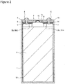
- FIG. 2 is a vertical sectional view including line A-A in FIG. 1
- the non-aqueous electrolyte secondary battery 100 comprises a battery case 20 that includes an outer package 1 having an opening, and a sealing plate 2 for sealing the opening.
- the outer package 1 and the sealing plate 2 are preferably made of metal and can be made of, for example, aluminum or an aluminum alloy.
- the outer package 1 is a rectangular bottomed cylindrical outer package having a bottom and a sidewall and having an opening at a position facing the bottom.
- the non-aqueous electrolyte secondary battery 100 illustrated in FIG. 1 is an example of the rectangular non-aqueous electrolyte secondary battery having the rectangular outer package 1 (rectangular battery case 20)
- the non-aqueous electrolyte secondary battery of the present embodiment is not limited thereto but may be a laminated outer package non-aqueous electrolyte secondary battery or the like having an outer package (a battery case made of a laminate sheet) using a laminate sheet formed by laminating metal foil with a resin sheet.
- the sealing plate 2 is connected to the opening edge of the rectangular outer package 1 by laser welding or the like.
- the sealing plate 2 has an electrolyte injection hole 13.
- the electrolyte injection hole 13 is sealed by a sealing plug 14 after an electrolyte to be described later is injected.
- the sealing plate 2 has a gas discharge valve 15.
- the gas discharge valve 15 operates when the pressure inside the battery reaches or exceeds a predetermined value, and discharges the gas inside the battery to the outside of the battery.
- a positive electrode terminal 4 is attached to the sealing plate 2 so as to project outside the battery case 20. Specifically, the positive electrode terminal 4 is inserted into a positive electrode terminal attachment hole formed in the sealing plate 2 and is attached to the sealing plate 2 in a state of being electrically insulated from the sealing plate 2 by an outer insulating member 9 disposed at the positive electrode terminal attachment hole outside the battery and an inner insulating member 8 disposed inside the battery. The positive electrode terminal 4 is electrically connected to a positive electrode current collector 5 in the battery case 20.
- the positive electrode current collector 5 is provided on the sealing plate 2 across the inner insulating member 8.
- the inner insulating member 8 and the outer insulating member 9 are preferably made of resin.
- a negative electrode terminal 6 is attached to the sealing plate 2 so as to project outside the battery case 20. Specifically, the negative electrode terminal 6 is inserted into a negative electrode terminal attachment hole formed in the sealing plate 2 and is attached to the sealing plate 2 in a state of being electrically insulated from the sealing plate 2 by an outer insulating member 11 disposed at the negative electrode terminal attachment hole outside the battery and an inner insulating member 10 disposed inside the battery. The negative electrode terminal 6 is electrically connected to a negative electrode current collector 7 in the battery case 20. The negative electrode current collector 7 is provided on the sealing plate 2 across the inner insulating member 10.
- the inner insulating member 10 and the outer insulating member 11 are preferably made of resin.
- the non-aqueous electrolyte secondary battery 100 comprises the wound electrode assembly 3 and the electrolyte solution, and the outer package 1 houses the wound electrode assembly 3 and the electrolyte solution.
- the wound electrode assembly 3 has a winding structure in which the positive electrode plate 30 and the negative electrode plate 31 are wound with a separator 32 interposed therebetween.
- a positive electrode tab 30c and a negative electrode tab 31c project from a positive electrode plate 30 and a negative electrode plate 31, respectively, and the positive electrode tab 30c and the negative electrode tab 31c are connected to the positive electrode current collector 5 and the negative electrode current collector 7, respectively, by welding or the like.
- the non-aqueous electrolyte secondary battery 100 may comprise an insulating sheet 12 disposed between the wound electrode assembly 3 and the outer package 1.
- the insulating sheet 12 has, for example, a bottomed box shape or a bag shape having an opening at the top, like the outer package 1. Since the insulating sheet 12 has a bottomed box shape or a bag shape having the opening at the top, the wound electrode assembly 3 can be inserted from the opening of the insulating sheet 12, and the wound electrode assembly 3 can be covered with the insulating sheet 12.
- the material of the insulating sheet 12 is not particularly limited so long as being a material that has electrical insulating properties, chemical stability of not being affected by the electrolyte solution, and electrical stability of not electrolyzing with the voltage of the non-aqueous electrolyte secondary battery 100.
- a resin material such as polyethylene, polypropylene or polyfluoroethylene can be used from the viewpoints of industrial versatility, manufacturing cost, and quality stability.
- the insulating sheet 12 is not limited to a case shape such as the box shape or bag shape described above.
- the insulating sheet 12 having a planar shape extending in the two directions of the lateral direction and the vertical direction may be wound around the wound electrode assembly 3 in the two directions of the lateral direction and the vertical direction.
- the wound electrode assembly 3 can be covered with the planar insulating sheet 12.
- the electrolyte solution includes a solvent and an electrolyte salt dissolved in the solvent.
- a non-aqueous solvent can be used as the solvent.
- the non-aqueous solvent there may be used, for example, carbonates, esters, ethers, nitriles, amides, and a mixed solvent of two or more thereof.
- Examples of the carbonates include: cyclic carbonates such as ethylene carbonate (EC), propylene carbonate (PC), butylene carbonate, and vinylene carbonate; and chain carbonates such as dimethyl carbonate (DMC), ethyl methyl carbonate (EMC), diethyl carbonate (DEC), methyl propyl carbonate, ethyl propyl carbonate, and methyl isopropyl carbonate.
- the non-aqueous solvent may include a halogen substitute obtained by substituting at least a part of hydrogen of the above solvent with halogen atoms such as fluorine.
- the electrolyte solution is not limited to a liquid electrolyte but may be a solid electrolyte for which a gel-like polymer or the like is used.
- the electrolyte salt includes a lithium salt.
- the lithium salt there can be used LiPF6 or the like that is generally used as a supporting salt in the conventional non-aqueous electrolyte secondary battery 100.
- An additive such as vinylene carbonate (VC) can also be added as appropriate.
- FIG. 3 is a perspective view of the wound electrode assembly 3, with its winding outer end extended.
- the wound electrode assembly 3 has a body portion 3a and a tab portion 3b.
- the tab portion 3b is made up of a pair of a positive electrode tab 30c and a negative electrode tab 31c. Both the positive electrode tab 30c and the negative electrode tab 31c project upward from a gap in the winding center of the body portion 3a. Note that the positive electrode tab 30c and the negative electrode tab 31c may project from a position except for the winding center.
- a positive core body 30a extends to constitute the positive electrode tab 30c
- a negative core body 31a extends to constitute the negative electrode tab 31c
- Another conductive member can also be connected to the positive core body 30a or the negative core body 31a to form a positive electrode tab 30c or a negative electrode tab 31c.
- the base portion of the positive electrode tab 30c is preferably provided with an insulating layer or a protective layer having a higher electric resistance than that of the positive core body 30a.
- the body portion 3a is formed by pressing after removal of a winding core as described later, the front-side surface and the back-side surface are substantially parallel, and the right and left ends are curved and flat.
- the body portion 3a At the winding center of the body portion 3a, there is an elongated gap in the horizontal direction formed in a trace of the removal of the winding core, and the gap penetrates the body portion 3a in the vertical direction.
- the body portion 3a has a winding structure in which the positive electrode plate 30 and the negative electrode plate 31 are wound with the separator 32 interposed therebetween.
- the positive electrode plate 30 has the positive core body 30a made of metal and a positive electrode mixture layer 30b formed on the positive core body 30a and including a positive electrode active material.
- As the positive core body 30a there is used foil of metal, such as aluminum, stable in the potential range of the positive electrode plate 30, a film with the metal disposed on the surface layer, or the like.
- the thickness of the positive core body 30a is, for example, 10 to 20 ⁇ m.
- the negative electrode plate 31 has the negative core body 31a made of metal and a negative electrode mixture layer 31b formed on the negative core body 31a and including a negative electrode active material.
- the negative core body 31a it is possible to use foil of metal, such as copper, stable in the potential range of the negative electrode plate 31, a film with the metal disposed on the surface layer, or the like.
- the thickness of the negative core body 31a is, for example, 5 to 15 ⁇ m.
- the size of the positive electrode plate 30 is preferably slightly smaller than the size of the negative electrode plate 31 in both the axial direction and the winding direction.
- the softness index of the positive electrode plate 30 used for the wound electrode assembly 3 is 15 to 19.
- the softness index is an index indicating the softness of the positive electrode plate 30, and the larger the value of the softness index, the softer the positive electrode plate 30 is.
- the softness index of the conventional positive electrode plate 30 not having a high density of the positive electrode active material in the positive electrode mixture layer 30b, that is, not made to have a high packing density, is larger than 19, and for example, 22.
- the softness index is large, the positive electrode plate 30 or the negative electrode plate 31 included in the wound electrode assembly 3 tends to buckle after the winding body is pressed.
- the softness index is smaller than 13, the positive electrode plate 30 included in the wound electrode assembly 3 is excessively hard and tends to crack.
- the softness index of the positive electrode plate 30 is measured by the following procedure (hereinafter, sometimes referred to as a "positive electrode winding test”):
- the positive electrode mixture layer 30b includes a positive electrode active material, a binder, and a conductive agent and is preferably provided on each side of the positive core body 30a.
- the positive electrode plate 30 can be produced by applying a positive electrode active material slurry including the positive electrode active material, the binder, the conductive agent, and the like on the positive core body 30a, drying the coated film, and then compressing the coated film with a roller or the like to form the positive electrode mixture layer 30b on each side of the positive core body 30a.
- x + a 1, -0.2 ⁇ x ⁇ 0.2, -0.1 ⁇ b ⁇ 0.1
- M includes Ni and Co and includes at least one element selected from the group consisting of Mn and Al.
- a small amount of another lithium metal composite oxide or the like may be included as the positive electrode active material, but the lithium metal composite oxide represented by the above general formula is preferably used as the main component.
- the lithium metal composite oxide may include other elements except for Ni, Co, Mn, and Al.
- other elements include alkali metal elements except for Li, transition metal elements except for Ni, Co, and Mn, alkaline earth metal elements, Group 12 elements, Group 13 elements except for Al, and Group 14 elements.
- Zr, B, Mg, Ti, Fe, Cu, Zn, Sn, Na, K, Ba, Sr, Ca, W, Mo, Nb, Si, and the like can be exemplified.
- inorganic compound particles such as zirconium oxide, tungsten oxide, aluminum oxide, and lanthanoid-containing compounds may be fixed to the particle surface of the lithium metal composite oxide.
- the particle size of the lithium metal composite oxide is not particularly limited but, for example, the average particle size is preferably 2 ⁇ m or more and less than 30 ⁇ m. When the average particle size is less than 2 ⁇ m, there is a case where the resistance increases by inhibiting the conduction of electricity by the conductive agent in the positive electrode mixture layer 30b. On the other hand, when the average particle size is 30 ⁇ m or more, the load characteristic may be lowered due to a decrease in the reaction area.
- the average particle size means a volume average particle size measured by a laser diffraction method and a median diameter at which a volume integrated value is 50% in a particle size distribution. The average particle size can be measured, for example, by using a laser diffraction scattering particle size distribution measuring device (manufactured by HORIBA, Ltd.).
- binder included in the positive electrode mixture layer 30b examples include fluorine resins such as polytetrafluoroethylene (PTFE) and polyvinylidene fluoride (PVdF), polyacrylonitrile (PAN), polyimide resins, acrylic resins, and polyolefin resins.
- PTFE polytetrafluoroethylene
- PVdF polyvinylidene fluoride
- PAN polyacrylonitrile
- polyimide resins acrylic resins
- polyolefin resins polyolefin resins
- Examples of the conductive agent included in the positive electrode mixture layer 30b include carbon materials such as carbon black (CB), acetylene black (AB), Ketjen black, and graphite. These materials may be used alone or as a mixture of a plurality of materials.
- the positive electrode mixture layer 30b has a packing density of 3.2 g/cm 3 to 3.8 g/cm 3 . With the packing density in this range, it is possible to provide the non-aqueous electrolyte secondary battery 100 that comprises the positive electrode plate 30 made to have a high packing density, while preventing the cracking of the positive electrode mixture layer 30b and the buckling of the positive electrode plate 30 or the negative electrode plate 31.
- the negative electrode mixture layer 31b includes a negative electrode active material and a binder and is preferably provided on each side of the negative core body 31a.
- the negative electrode plate 31 can be produced by applying a negative electrode active material slurry including the negative electrode active material, the binder, and the like on the negative core body 31a, drying the coating film, and then compressing the coated film with a roller or the like to form the negative electrode mixture layer 31b on each side of the negative core body 31a.
- Examples of the negative electrode active material include low-crystalline carbon-coated graphite obtained by forming a low-crystalline carbon coating on the surface of graphite.
- the low-crystalline carbon is an amorphous or microcrystalline carbon material in a turbulent layer structure with a graphite crystal structure not developed or is a carbon material having a very fine particle size instead of a spherical shape or a scale shape.
- a carbon material having a d(002) plane spacing larger than 0.340 nm by X-ray diffraction is the low-crystalline carbon.
- a carbon material which is observed with a scanning electron microscope (SEM) or the like and has a measured average particle size of primary particles of 1 ⁇ m or less, is also the low-crystalline carbon.
- the low-crystalline carbon examples include hard carbon (hardly graphitized carbon), soft carbon (easily graphitized carbon), carbon black such as acetylene black, Ketjen black, thermal black, furnace black, carbon fiber, activated carbon, and the like.
- the negative electrode active material is not particularly limited so long as being able to reversibly adsorb and release lithium ions, and there can be used, for example, a carbon material such as natural graphite or artificial graphite, a metal alloyed with Li such as silicon (Si) or tin (Sn), or an oxide including a metal element such as Si or Sn.
- the negative electrode mixture layer 31b may include a lithium-titanium composite oxide.
- binder included in the negative electrode mixture layer 31b a known binder can be used, and as in the case of the positive electrode, fluorine resins such as PTFE or (PVdF), PAN, polyimide resins, acrylic resins, polyolefin resins, and the like can be used.
- fluorine resins such as PTFE or (PVdF), PAN, polyimide resins, acrylic resins, polyolefin resins, and the like can be used.
- the binder used in the case of preparing the negative electrode mixture slurry by using an aqueous solvent may include CMC or a salt thereof, styrene-butadiene rubber (SBR), poly acrylic acid (PAA) or a salt thereof, and polyvinyl alcohol (PVA).
- a porous sheet having ion permeability and insulating properties is used for the separator 32.
- the porous sheet include a microporous film, a woven fabric, and a nonwoven fabric or the like.
- the material of the separator 32 is preferably olefin resins such as polyethylene and polypropylene, cellulose, and the like.
- the separator 32 may be a laminate having a cellulose fiber layer and a thermoplastic resin fiber layer such as an olefin resin.
- the separator may be a multilayer separator including a polyethylene layer and a polypropylene layer, and there can also be used a separator applied with a resin such as an aramid resin or inorganic fine particles such as alumina or titania on the surface of the separator 32.
- a resin such as an aramid resin or inorganic fine particles such as alumina or titania
- FIG. 4 illustrates a change in shape from a winding body 40 before pressing to the wound electrode assembly 3 after pressing (the positive electrode tab 30c or the negative electrode tab 31c is not illustrated).
- the three upper drawings are plan views of the winding body 40 before pressing and illustrate cases where the shapes of winding core 41 are a circular, elliptical, and flat rectangular, respectively, from left to right.
- the circular, elliptical, and flat rectangular shapes are distinguished by the ratio of the major axis (w1, w2, w3) and the minor axis (t1, t2, t3) passing through the center of each shape and intersecting at right angles to each other.
- the circular shape includes a true circular shape and a substantially circular shape and refers to a case where a ratio (hereinafter referred to as a flatness ratio) t1/w1 of the length of the minor axis to the length of the major axis is 95% or more and 100% or less.
- the elliptical shape is a shape flatter than the circular shape, and the flatness ratio t2/w2 is 71% or more and less than 95%.
- the flat rectangular shape is a shape flatter than the ellipse, and the flatness ratio t3/w3 is less than 71%. Note that the flat rectangular shape may have rounded corners.
- the positive electrode plate 30, the negative electrode plate 31, and the separator 32 are wound around the elliptical winding core 41 illustrated in FIG. 4(b) to form the winding body 40.
- Forming the elliptical shape can prevent buckling because the change in shape at the time of pressing is smaller than in the case of the circular shape.
- the flatness ratio is as small as in the case of the flat rectangular shape, cracking tends to occur because the positive electrode plate 30 is curved at the right and left ends of the winding core 41, and the elliptical shape is more preferable than the flat rectangular shape.
- the winding body 40 formed in the winding body formation step is pressed after the removal of the winding core 41 to form a flat electrode assembly in an electrode assembly formation step.
- the three lower drawings are plan views of the wound electrode assembly 3 after pressing. Even when the winding core 41 has any of the circular, elliptical, and flat rectangular shapes, the shape can be substantially the same after pressing.
- the ratio of the longest inner peripheral diameter of the winding body 40 to the longest inner peripheral diameter of the wound electrode assembly 3 can be set to 71% to 94%.
- the longest inner peripheral diameter is the longest dimension in a period when the wound electrode assembly 3 or the winding body 40 goes around the winding center from the winding inner end.
- the ratio of the longest inner peripheral diameter of the winding body 40 to the longest inner peripheral diameter of the wound electrode assembly 3 is w1/w4, w2/w5, or w3/w6, respectively.
- the positive electrode plate was cut into dimensions of 50 mm in width and 100 mm in length, wound around a core rod having a diameter of 5 mm, held for 60 seconds, and then released.
- the diameter of the positive electrode plate having sprung back was measured as a softness index.
- the softness index of the positive electrode plate was 19.
- the positive electrode plate having a length of 500 mm and a width of 75 mm and the negative electrode plate having a length of 500 mm and a width of 78 mm were superimposed via a separator made of a microporous polypropylene film having a thickness of 16 ⁇ m, fixed at one end, and wound around an elliptical winding core having a flatness ratio of 85%.
- the winding end was fixed with a tape, the winding core was removed, and press-formation is performed to produce a wound electrode assembly. From the appearances of the positive electrode plate and negative electrode plate obtained by dissembling the wound electrode assembly after pressing, it was confirmed that no cracking or buckling had occurred in the positive electrode plate and the negative electrode plate.
- Example 2 and Example 3 the positive electrode winding test and the evaluation of the wound electrode assembly were performed in the same manner as in Example 1, except that the hardness of the positive electrode mixture layer was adjusted by changing the amount of the binder included in the positive electrode mixture slurry to 3% by mass for the positive electrode active material and 4% by mass for the positive electrode active material, respectively.
- the softness indices of the positive electrode winding tests of Example 2 and Example 3 were 17 and 15, respectively.
- Comparative Example 1 the wound electrode assembly was evaluated in the same manner as in Example 1, except that the hardness of the positive electrode mixture layer was adjusted by changing the amount of binder included in the positive electrode mixture slurry to 5% by mass relative to the positive electrode active material.
- the softness index by the positive electrode winding test of Comparative Example 1 was 13.
- Comparative Examples 2 to 5 the positive electrode winding test and the evaluation of the wound electrode assembly were performed in the same manner as in Examples 1 to 3 and Comparative Example 1, except that the shape of the winding core was changed to a circular shape having a flatness ratio of 95%.
- Comparative Examples 6 to 9 the positive electrode winding test and the evaluation of the wound electrode assembly were performed in the same manner as in Example 1 to 3 and Comparative Example 1, except that the shape of the winding core was changed to a flat rectangular shape having a flatness ratio of 64%.
Landscapes
- Chemical & Material Sciences (AREA)
- Chemical Kinetics & Catalysis (AREA)
- Electrochemistry (AREA)
- General Chemical & Material Sciences (AREA)
- Engineering & Computer Science (AREA)
- Manufacturing & Machinery (AREA)
- Inorganic Chemistry (AREA)
- Materials Engineering (AREA)
- Secondary Cells (AREA)
- Battery Electrode And Active Subsutance (AREA)
Abstract
Description
- The present disclosure relates to a method for manufacturing a non-aqueous electrolyte secondary battery and a non-aqueous electrolyte secondary battery.
- In recent years, there has been an increasing demand for higher capacity of a non-aqueous electrolyte secondary battery used in a vehicle such as an electric vehicle, and it has become necessary to introduce more active materials into a limited space in a battery to increase a packing density of an electrode plate. Particularly, in a non-aqueous electrolyte secondary battery comprising a wound electrode assembly in which a positive electrode plate and a negative electrode plate are wound with a separator interposed therebetween, it is a problem that cracking occurs in a positive electrode mixture layer when the positive electrode plate is made to have a high packing density. On the other hand, in the wound electrode assembly, it is known that a phenomenon of buckling in which the positive electrode plate or the negative electrode plate bends inside the battery occurs under certain conditions.
Patent Literature 1 discloses a positive electrode mixture layer in which two layers having different compounding ratios of binders included in the respective layers are superimposed. - PATENT LITERATURE 1:
Japanese Unexamined Patent Application Publication No. 2017-84769 - However, in the method disclosed in
Patent Literature 1, it is not possible to prevent the occurrence of cracking of the positive electrode mixture layer made to have a high packing density, and the buckling of the positive electrode plate or the negative electrode plate is not considered, so there is still room for improvement. - Accordingly, it is an advantage of the present disclosure to provide a non-aqueous electrolyte secondary battery that prevents the cracking of a positive electrode mixture layer in a positive electrode plate made to have a high packing density and prevents the buckling of the positive electrode plate or a negative electrode plate.
- A non-aqueous electrolyte secondary battery as one embodiment of the present disclosure is a non-aqueous electrolyte secondary battery comprises: a flat wound electrode assembly in which a positive electrode plate and a negative electrode plate are wound with a separator interposed therebetween. The positive electrode plate includes a positive core body and a positive electrode mixture layer formed on each side of the positive core body. The positive electrode mixture layer includes a lithium metal composite oxide represented by general formula Li1+xMaO2+b (where x, a, and b satisfy conditions that x + a = 1, -0.2 < x ≤ 0.2, -0.1 ≤ b ≤ 0.1, and M includes Ni and Co and includes at least one element selected from the group consisting of Mn and Al). A softness index of the positive electrode plate is 15 to 19.
- A method for manufacturing a non-aqueous electrolyte secondary battery as one aspect of the present disclosure is a method for manufacturing a non-aqueous electrolyte secondary battery, the method including: a winding body formation step of winding a positive electrode plate, a negative electrode plate, and a separator around an elliptical winding core to form a winding body; and an electrode assembly formation step of removing the winding core from the winding body and then pressing the winding body to form a flat wound electrode assembly. The positive electrode plate includes a positive core body and a positive electrode mixture layer formed on each side of the positive core body. The positive electrode mixture layer includes a lithium metal composite oxide represented by general formula Li1+xMaO2+b (where x, a, and b satisfy conditions that x + a = 1, -0.2 < x ≤ 0.2, -0.1 ≤ b ≤ 0.1, and M includes Ni and Co and includes at least one element selected from the group consisting of Mn and Al). A softness index of the positive electrode plate is 15 to 19.
- According to one aspect of the present disclosure, it is possible to provide a non-aqueous electrolyte secondary battery that prevents the cracking of a positive electrode mixture layer in a positive electrode plate made to have a high packing density and prevents the buckling of the positive electrode plate or a negative electrode plate.
-
-
FIG. 1 is a perspective view of a rectangular non-aqueous electrolyte secondary battery that is an example of an embodiment. -
FIG. 2 is a sectional view taken along line A-A ofFIG. 1 . -
FIG. 3 is a perspective view of a wound electrode assembly of the non-aqueous electrolyte secondary battery illustrated inFIG. 2 , with its winding outer end extended. -
FIG. 4 is a plan view illustrating a change in shape from a winding body before pressing to the wound electrode assembly after pressing. - An example of an embodiment will be described in detail below. In the present specification, the longitudinal direction in
FIGS. 1 to 3 may be represented by "top and bottom," the lateral direction by "left and right," and the depth direction by "front and back." - With reference to
FIGS. 1 and2 , a configuration of a non-aqueous electrolytesecondary battery 100 as an example of the embodiment will be described.FIG. 1 is a perspective view illustrating the appearance of the non-aqueous electrolytesecondary battery 100 as an example of the embodiment, andFIG. 2 is a vertical sectional view including line A-A inFIG. 1 . As illustrated inFIGS. 1 to 2 , the non-aqueous electrolytesecondary battery 100 comprises abattery case 20 that includes anouter package 1 having an opening, and asealing plate 2 for sealing the opening. Theouter package 1 and thesealing plate 2 are preferably made of metal and can be made of, for example, aluminum or an aluminum alloy. Theouter package 1 is a rectangular bottomed cylindrical outer package having a bottom and a sidewall and having an opening at a position facing the bottom. Although the non-aqueous electrolytesecondary battery 100 illustrated inFIG. 1 is an example of the rectangular non-aqueous electrolyte secondary battery having the rectangular outer package 1 (rectangular battery case 20), the non-aqueous electrolyte secondary battery of the present embodiment is not limited thereto but may be a laminated outer package non-aqueous electrolyte secondary battery or the like having an outer package (a battery case made of a laminate sheet) using a laminate sheet formed by laminating metal foil with a resin sheet. Thesealing plate 2 is connected to the opening edge of the rectangularouter package 1 by laser welding or the like. - The
sealing plate 2 has anelectrolyte injection hole 13. Theelectrolyte injection hole 13 is sealed by asealing plug 14 after an electrolyte to be described later is injected. Thesealing plate 2 has agas discharge valve 15. Thegas discharge valve 15 operates when the pressure inside the battery reaches or exceeds a predetermined value, and discharges the gas inside the battery to the outside of the battery. - A
positive electrode terminal 4 is attached to thesealing plate 2 so as to project outside thebattery case 20. Specifically, thepositive electrode terminal 4 is inserted into a positive electrode terminal attachment hole formed in thesealing plate 2 and is attached to thesealing plate 2 in a state of being electrically insulated from thesealing plate 2 by an outer insulating member 9 disposed at the positive electrode terminal attachment hole outside the battery and an inner insulatingmember 8 disposed inside the battery. Thepositive electrode terminal 4 is electrically connected to a positive electrodecurrent collector 5 in thebattery case 20. The positive electrodecurrent collector 5 is provided on thesealing plate 2 across the innerinsulating member 8. The innerinsulating member 8 and the outer insulating member 9 are preferably made of resin. - A
negative electrode terminal 6 is attached to thesealing plate 2 so as to project outside thebattery case 20. Specifically, thenegative electrode terminal 6 is inserted into a negative electrode terminal attachment hole formed in thesealing plate 2 and is attached to thesealing plate 2 in a state of being electrically insulated from thesealing plate 2 by an outer insulatingmember 11 disposed at the negative electrode terminal attachment hole outside the battery and an inner insulatingmember 10 disposed inside the battery. Thenegative electrode terminal 6 is electrically connected to a negative electrodecurrent collector 7 in thebattery case 20. The negative electrodecurrent collector 7 is provided on thesealing plate 2 across the innerinsulating member 10. The innerinsulating member 10 and the outer insulatingmember 11 are preferably made of resin. - The non-aqueous electrolyte
secondary battery 100 comprises thewound electrode assembly 3 and the electrolyte solution, and theouter package 1 houses thewound electrode assembly 3 and the electrolyte solution. As will be described later with reference toFIG. 3 , thewound electrode assembly 3 has a winding structure in which thepositive electrode plate 30 and thenegative electrode plate 31 are wound with aseparator 32 interposed therebetween. At the top of thewound electrode assembly 3, apositive electrode tab 30c and anegative electrode tab 31c project from apositive electrode plate 30 and anegative electrode plate 31, respectively, and thepositive electrode tab 30c and thenegative electrode tab 31c are connected to the positiveelectrode current collector 5 and the negative electrodecurrent collector 7, respectively, by welding or the like. - As illustrated in
FIG. 2 , the non-aqueous electrolytesecondary battery 100 may comprise aninsulating sheet 12 disposed between thewound electrode assembly 3 and theouter package 1. Theinsulating sheet 12 has, for example, a bottomed box shape or a bag shape having an opening at the top, like theouter package 1. Since theinsulating sheet 12 has a bottomed box shape or a bag shape having the opening at the top, thewound electrode assembly 3 can be inserted from the opening of theinsulating sheet 12, and thewound electrode assembly 3 can be covered with theinsulating sheet 12. - The material of the
insulating sheet 12 is not particularly limited so long as being a material that has electrical insulating properties, chemical stability of not being affected by the electrolyte solution, and electrical stability of not electrolyzing with the voltage of the non-aqueous electrolytesecondary battery 100. As the material of theinsulating sheet 12, for example, a resin material such as polyethylene, polypropylene or polyfluoroethylene can be used from the viewpoints of industrial versatility, manufacturing cost, and quality stability. Note that theinsulating sheet 12 is not limited to a case shape such as the box shape or bag shape described above. For example, theinsulating sheet 12 having a planar shape extending in the two directions of the lateral direction and the vertical direction may be wound around thewound electrode assembly 3 in the two directions of the lateral direction and the vertical direction. Thus, thewound electrode assembly 3 can be covered with theplanar insulating sheet 12. - The electrolyte solution includes a solvent and an electrolyte salt dissolved in the solvent. A non-aqueous solvent can be used as the solvent. As the non-aqueous solvent, there may be used, for example, carbonates, esters, ethers, nitriles, amides, and a mixed solvent of two or more thereof. Examples of the carbonates include: cyclic carbonates such as ethylene carbonate (EC), propylene carbonate (PC), butylene carbonate, and vinylene carbonate; and chain carbonates such as dimethyl carbonate (DMC), ethyl methyl carbonate (EMC), diethyl carbonate (DEC), methyl propyl carbonate, ethyl propyl carbonate, and methyl isopropyl carbonate. The non-aqueous solvent may include a halogen substitute obtained by substituting at least a part of hydrogen of the above solvent with halogen atoms such as fluorine. Note that the electrolyte solution is not limited to a liquid electrolyte but may be a solid electrolyte for which a gel-like polymer or the like is used. The electrolyte salt includes a lithium salt. As the lithium salt, there can be used LiPF6 or the like that is generally used as a supporting salt in the conventional non-aqueous electrolyte
secondary battery 100. An additive such as vinylene carbonate (VC) can also be added as appropriate. - Next, the
wound electrode assembly 3 will be described in detail with reference toFIG. 3. FIG. 3 is a perspective view of thewound electrode assembly 3, with its winding outer end extended. Thewound electrode assembly 3 has abody portion 3a and atab portion 3b. - The
tab portion 3b is made up of a pair of apositive electrode tab 30c and anegative electrode tab 31c. Both thepositive electrode tab 30c and thenegative electrode tab 31c project upward from a gap in the winding center of thebody portion 3a. Note that thepositive electrode tab 30c and thenegative electrode tab 31c may project from a position except for the winding center. - In the present embodiment, a positive
core body 30a extends to constitute thepositive electrode tab 30c, and anegative core body 31a extends to constitute thenegative electrode tab 31c. Another conductive member can also be connected to thepositive core body 30a or thenegative core body 31a to form apositive electrode tab 30c or anegative electrode tab 31c. The base portion of thepositive electrode tab 30c is preferably provided with an insulating layer or a protective layer having a higher electric resistance than that of thepositive core body 30a. - Since the
body portion 3a is formed by pressing after removal of a winding core as described later, the front-side surface and the back-side surface are substantially parallel, and the right and left ends are curved and flat. At the winding center of thebody portion 3a, there is an elongated gap in the horizontal direction formed in a trace of the removal of the winding core, and the gap penetrates thebody portion 3a in the vertical direction. - The
body portion 3a has a winding structure in which thepositive electrode plate 30 and thenegative electrode plate 31 are wound with theseparator 32 interposed therebetween. Thepositive electrode plate 30 has thepositive core body 30a made of metal and a positiveelectrode mixture layer 30b formed on thepositive core body 30a and including a positive electrode active material. As thepositive core body 30a, there is used foil of metal, such as aluminum, stable in the potential range of thepositive electrode plate 30, a film with the metal disposed on the surface layer, or the like. The thickness of thepositive core body 30a is, for example, 10 to 20 µm. Thenegative electrode plate 31 has thenegative core body 31a made of metal and a negativeelectrode mixture layer 31b formed on thenegative core body 31a and including a negative electrode active material. As thenegative core body 31a, it is possible to use foil of metal, such as copper, stable in the potential range of thenegative electrode plate 31, a film with the metal disposed on the surface layer, or the like. The thickness of thenegative core body 31a is, for example, 5 to 15 µm. In the non-aqueous electrolytesecondary battery 100, the size of thepositive electrode plate 30 is preferably slightly smaller than the size of thenegative electrode plate 31 in both the axial direction and the winding direction. - The softness index of the
positive electrode plate 30 used for thewound electrode assembly 3 is 15 to 19. The softness index is an index indicating the softness of thepositive electrode plate 30, and the larger the value of the softness index, the softer thepositive electrode plate 30 is. The softness index of the conventionalpositive electrode plate 30 not having a high density of the positive electrode active material in the positiveelectrode mixture layer 30b, that is, not made to have a high packing density, is larger than 19, and for example, 22. When the softness index is large, thepositive electrode plate 30 or thenegative electrode plate 31 included in thewound electrode assembly 3 tends to buckle after the winding body is pressed. When the softness index is smaller than 13, thepositive electrode plate 30 included in thewound electrode assembly 3 is excessively hard and tends to crack. - The softness index of the
positive electrode plate 30 is measured by the following procedure (hereinafter, sometimes referred to as a "positive electrode winding test"): - (1) A
positive electrode plate 30 having a width of 50 mm and a length of 100 mm is wound around a core rod having a diameter of 5 mm and held for 60 seconds. - (2) When the
positive electrode plate 30 is released with the core rod facing in the vertical direction, thepositive electrode plate 30 springs back and expands away from the core rod. - (3) A value obtained by subtracting the unit (mm) from the inner diameter of the
positive electrode plate 30 after the spring-back is taken as the softness index of thepositive electrode plate 30. The inner diameter of thepositive electrode plate 30 means the length of the diameter passing through the position of thepositive electrode plate 30 farthest from the center of the core rod and the center of the core rod in a period when thepositive electrode plate 30 goes around the core rod from the winding inner end. - The positive
electrode mixture layer 30b includes a positive electrode active material, a binder, and a conductive agent and is preferably provided on each side of thepositive core body 30a. Thepositive electrode plate 30 can be produced by applying a positive electrode active material slurry including the positive electrode active material, the binder, the conductive agent, and the like on thepositive core body 30a, drying the coated film, and then compressing the coated film with a roller or the like to form the positiveelectrode mixture layer 30b on each side of thepositive core body 30a. - As the positive electrode active material, there is included a lithium metal composite oxide represented by general formula Li1+xMaO2+b (where x, a, and b satisfy conditions that x + a = 1, -0.2 < x ≤ 0.2, -0.1 ≤ b ≤ 0.1, and M includes Ni and Co and includes at least one element selected from the group consisting of Mn and Al). A small amount of another lithium metal composite oxide or the like may be included as the positive electrode active material, but the lithium metal composite oxide represented by the above general formula is preferably used as the main component.
- The lithium metal composite oxide may include other elements except for Ni, Co, Mn, and Al. Examples of other elements include alkali metal elements except for Li, transition metal elements except for Ni, Co, and Mn, alkaline earth metal elements,
Group 12 elements,Group 13 elements except for Al, andGroup 14 elements. Specifically, Zr, B, Mg, Ti, Fe, Cu, Zn, Sn, Na, K, Ba, Sr, Ca, W, Mo, Nb, Si, and the like can be exemplified. Note that inorganic compound particles such as zirconium oxide, tungsten oxide, aluminum oxide, and lanthanoid-containing compounds may be fixed to the particle surface of the lithium metal composite oxide. - The particle size of the lithium metal composite oxide is not particularly limited but, for example, the average particle size is preferably 2 µm or more and less than 30 µm. When the average particle size is less than 2 µm, there is a case where the resistance increases by inhibiting the conduction of electricity by the conductive agent in the positive
electrode mixture layer 30b. On the other hand, when the average particle size is 30 µm or more, the load characteristic may be lowered due to a decrease in the reaction area. The average particle size means a volume average particle size measured by a laser diffraction method and a median diameter at which a volume integrated value is 50% in a particle size distribution. The average particle size can be measured, for example, by using a laser diffraction scattering particle size distribution measuring device (manufactured by HORIBA, Ltd.). - Examples of the binder included in the positive
electrode mixture layer 30b include fluorine resins such as polytetrafluoroethylene (PTFE) and polyvinylidene fluoride (PVdF), polyacrylonitrile (PAN), polyimide resins, acrylic resins, and polyolefin resins. By adjusting the hardness of thepositive electrode plate 30 with the binder, the softness index of thewound electrode assembly 3 can be adjusted. - Examples of the conductive agent included in the positive
electrode mixture layer 30b include carbon materials such as carbon black (CB), acetylene black (AB), Ketjen black, and graphite. These materials may be used alone or as a mixture of a plurality of materials. - The positive
electrode mixture layer 30b has a packing density of 3.2 g/cm3 to 3.8 g/cm3. With the packing density in this range, it is possible to provide the non-aqueous electrolytesecondary battery 100 that comprises thepositive electrode plate 30 made to have a high packing density, while preventing the cracking of the positiveelectrode mixture layer 30b and the buckling of thepositive electrode plate 30 or thenegative electrode plate 31. - The negative
electrode mixture layer 31b includes a negative electrode active material and a binder and is preferably provided on each side of thenegative core body 31a. Thenegative electrode plate 31 can be produced by applying a negative electrode active material slurry including the negative electrode active material, the binder, and the like on thenegative core body 31a, drying the coating film, and then compressing the coated film with a roller or the like to form the negativeelectrode mixture layer 31b on each side of thenegative core body 31a. - Examples of the negative electrode active material include low-crystalline carbon-coated graphite obtained by forming a low-crystalline carbon coating on the surface of graphite. The low-crystalline carbon is an amorphous or microcrystalline carbon material in a turbulent layer structure with a graphite crystal structure not developed or is a carbon material having a very fine particle size instead of a spherical shape or a scale shape. For example, a carbon material having a d(002) plane spacing larger than 0.340 nm by X-ray diffraction is the low-crystalline carbon. In addition, a carbon material, which is observed with a scanning electron microscope (SEM) or the like and has a measured average particle size of primary particles of 1 µm or less, is also the low-crystalline carbon. Specific examples of the low-crystalline carbon include hard carbon (hardly graphitized carbon), soft carbon (easily graphitized carbon), carbon black such as acetylene black, Ketjen black, thermal black, furnace black, carbon fiber, activated carbon, and the like. The negative electrode active material is not particularly limited so long as being able to reversibly adsorb and release lithium ions, and there can be used, for example, a carbon material such as natural graphite or artificial graphite, a metal alloyed with Li such as silicon (Si) or tin (Sn), or an oxide including a metal element such as Si or Sn. The negative
electrode mixture layer 31b may include a lithium-titanium composite oxide. - As the binder included in the negative
electrode mixture layer 31b, a known binder can be used, and as in the case of the positive electrode, fluorine resins such as PTFE or (PVdF), PAN, polyimide resins, acrylic resins, polyolefin resins, and the like can be used. Examples of the binder used in the case of preparing the negative electrode mixture slurry by using an aqueous solvent may include CMC or a salt thereof, styrene-butadiene rubber (SBR), poly acrylic acid (PAA) or a salt thereof, and polyvinyl alcohol (PVA). - A porous sheet having ion permeability and insulating properties is used for the
separator 32. Specific examples of the porous sheet include a microporous film, a woven fabric, and a nonwoven fabric or the like. The material of theseparator 32 is preferably olefin resins such as polyethylene and polypropylene, cellulose, and the like. Theseparator 32 may be a laminate having a cellulose fiber layer and a thermoplastic resin fiber layer such as an olefin resin. The separator may be a multilayer separator including a polyethylene layer and a polypropylene layer, and there can also be used a separator applied with a resin such as an aramid resin or inorganic fine particles such as alumina or titania on the surface of theseparator 32. - Next, a method for manufacturing the
wound electrode assembly 3 will be described in detail with reference toFIG. 4. FIG. 4 illustrates a change in shape from a windingbody 40 before pressing to thewound electrode assembly 3 after pressing (thepositive electrode tab 30c or thenegative electrode tab 31c is not illustrated). The three upper drawings are plan views of the windingbody 40 before pressing and illustrate cases where the shapes of windingcore 41 are a circular, elliptical, and flat rectangular, respectively, from left to right. The circular, elliptical, and flat rectangular shapes are distinguished by the ratio of the major axis (w1, w2, w3) and the minor axis (t1, t2, t3) passing through the center of each shape and intersecting at right angles to each other. Here, the circular shape includes a true circular shape and a substantially circular shape and refers to a case where a ratio (hereinafter referred to as a flatness ratio) t1/w1 of the length of the minor axis to the length of the major axis is 95% or more and 100% or less. The elliptical shape is a shape flatter than the circular shape, and the flatness ratio t2/w2 is 71% or more and less than 95%. The flat rectangular shape is a shape flatter than the ellipse, and the flatness ratio t3/w3 is less than 71%. Note that the flat rectangular shape may have rounded corners. - In a winding body formation step, the
positive electrode plate 30, thenegative electrode plate 31, and theseparator 32 are wound around the elliptical windingcore 41 illustrated inFIG. 4(b) to form the windingbody 40. Forming the elliptical shape can prevent buckling because the change in shape at the time of pressing is smaller than in the case of the circular shape. When the flatness ratio is as small as in the case of the flat rectangular shape, cracking tends to occur because thepositive electrode plate 30 is curved at the right and left ends of the windingcore 41, and the elliptical shape is more preferable than the flat rectangular shape. - The winding
body 40 formed in the winding body formation step is pressed after the removal of the windingcore 41 to form a flat electrode assembly in an electrode assembly formation step. InFIG. 4 , the three lower drawings are plan views of thewound electrode assembly 3 after pressing. Even when the windingcore 41 has any of the circular, elliptical, and flat rectangular shapes, the shape can be substantially the same after pressing. - The ratio of the longest inner peripheral diameter of the winding
body 40 to the longest inner peripheral diameter of the wound electrode assembly 3 (longest inner peripheral diameter of windingbody 40/longest inner peripheral diameter of wound electrode assembly 3) can be set to 71% to 94%. The longest inner peripheral diameter is the longest dimension in a period when thewound electrode assembly 3 or the windingbody 40 goes around the winding center from the winding inner end. In the respective cases where the shapes of the windingcore 41 are circular, elliptical, and flat rectangular, the ratio of the longest inner peripheral diameter of the windingbody 40 to the longest inner peripheral diameter of thewound electrode assembly 3 is w1/w4, w2/w5, or w3/w6, respectively. - The present embodiment will be further described below with reference to examples, but the present disclosure is not limited to these examples.
- After mixing of Li1.054Ni0.199Co0.597Mn0.199Zr0.005O2 as a positive electrode active material, 5% by mass of carbon black relative to the positive electrode active material, and 2% by mass of polyvinylidene fluoride (PVdF) relative to the positive electrode active material are mixed, N-methyl-2 pyrrolidone (NMP) was added, and the mixture was stirred using a mixer (T.K. HIVIS MIX, manufactured by PRIMIX Corporation) to prepare a positive electrode mixture slurry. Aluminum foil having a thickness of 15 µm was coated with the slurry as a positive core body and then dried and compressed by a roller. In this way, there was produced a positive electrode plate having a thickness of 140 µm in which a positive electrode mixture layer was formed on each side of the positive core body.
- After mixing of low-crystalline carbon-coated graphite as a negative electrode active material, 1% by mass of styrene-butadiene rubber (SBR) relative to the negative electrode active material, and 0.5% by mass of carboxymethyl cellulose relative to the negative electrode active material, water was added, and the mixture was stirred using a mixer (T.K. HIVIS MIX, manufactured by PRIMIX Corporation) to prepare a negative electrode mixture slurry. Copper foil having a thickness of 10 µm was coated with the slurry as a negative core body and then dried and compressed by a roller. In this way, there was produced a negative electrode plate having a thickness of 160 µm, in which a negative electrode mixture layer was formed on each side of the negative core body.
- The positive electrode plate was cut into dimensions of 50 mm in width and 100 mm in length, wound around a core rod having a diameter of 5 mm, held for 60 seconds, and then released. The diameter of the positive electrode plate having sprung back was measured as a softness index. The softness index of the positive electrode plate was 19.
- The positive electrode plate having a length of 500 mm and a width of 75 mm and the negative electrode plate having a length of 500 mm and a width of 78 mm were superimposed via a separator made of a microporous polypropylene film having a thickness of 16 µm, fixed at one end, and wound around an elliptical winding core having a flatness ratio of 85%. Next, the winding end was fixed with a tape, the winding core was removed, and press-formation is performed to produce a wound electrode assembly. From the appearances of the positive electrode plate and negative electrode plate obtained by dissembling the wound electrode assembly after pressing, it was confirmed that no cracking or buckling had occurred in the positive electrode plate and the negative electrode plate.
- In Example 2 and Example 3, the positive electrode winding test and the evaluation of the wound electrode assembly were performed in the same manner as in Example 1, except that the hardness of the positive electrode mixture layer was adjusted by changing the amount of the binder included in the positive electrode mixture slurry to 3% by mass for the positive electrode active material and 4% by mass for the positive electrode active material, respectively. The softness indices of the positive electrode winding tests of Example 2 and Example 3 were 17 and 15, respectively.
- In Comparative Example 1, the wound electrode assembly was evaluated in the same manner as in Example 1, except that the hardness of the positive electrode mixture layer was adjusted by changing the amount of binder included in the positive electrode mixture slurry to 5% by mass relative to the positive electrode active material. The softness index by the positive electrode winding test of Comparative Example 1 was 13.
- In Comparative Examples 2 to 5, the positive electrode winding test and the evaluation of the wound electrode assembly were performed in the same manner as in Examples 1 to 3 and Comparative Example 1, except that the shape of the winding core was changed to a circular shape having a flatness ratio of 95%.
- In Comparative Examples 6 to 9, the positive electrode winding test and the evaluation of the wound electrode assembly were performed in the same manner as in Example 1 to 3 and Comparative Example 1, except that the shape of the winding core was changed to a flat rectangular shape having a flatness ratio of 64%.
[Table 1] Softness index of positive electrode plate Flatness ratio of winding core Longest inner peripheral diameter of winding body/longest inner peripheral diameter of wound electrode assembly Occurrence of cracking of positive electrode mixture layer Occurrence of buckling of positive electrode plate or negative electrode plate Overall Evaluation Example 1 19 80%(Elliptical) 80% No No Usable Example 2 17 80%(Elliptical) 80% No No Usable Example 3 15 80%(Elliptical) 80% No No Usable Comparative Example 1 13 80%(Elliptical) 80% Yes No Unusable (battery resistance is affected from initial stage) Comparative Example 2 19 95%(Circular) 64% No Yes Unusable (risk of short-circuit exists after endurance test) Comparative Example 3 17 95%(Circular) 64% No Yes Unusable (risk of short-circuit exists after endurance test) Comparative Example 4 15 95%(Circular) 64% No Yes Unusable (risk of short-circuit exists after endurance test) Comparative Example 5 13 95%(Circular) 64% Yes No Unusable (battery resistance is affected from initial stage) Comparative Example 6 19 64%(Flat rectangular) 95% Yes No Unusable (battery resistance is affected from initial stage) Comparative Example 7 17 64%(Flat rectangular) 95% Yes No Unusable (battery resistance is affected from initial stage) Comparative Example 8 15 64%(Flat rectangular) 95% Yes No Unusable (battery resistance is affected from initial stage) Comparative Example 9 13 64%(Flat rectangular) 95% Yes No Unusable (battery resistance is affected from initial stage) - As can be seen from Table 1, it was confirmed that in the wound electrode assembly produced by using the elliptical winding core having a softness index of 15 to 19, no cracking occurs in the positive electrode mixture layer, and no buckling occurs in the positive electrode plate and the negative electrode plate.
-
- 1
- outer package
- 2
- sealing plate
- 3
- wound electrode assembly
- 3a
- body portion
- 3b
- tab portion
- 4
- positive electrode terminal
- 5
- positive electrode current collector
- 6
- negative electrode terminal
- 7
- negative electrode current collector
- 8, 10
- inner insulating member
- 9, 11
- outer insulating member
- 12
- insulating sheet
- 13
- electrolyte injection hole
- 14
- sealing plug
- 15
- gas discharge valve
- 20
- battery case
- 30
- positive electrode plate
- 30a
- positive core body
- 30b
- positive electrode mixture layer
- 30c
- positive electrode tab
- 31
- negative electrode plate
- 31a
- negative core body
- 31b
- negative electrode mixture layer
- 31c
- negative electrode tab
- 32
- separator
- 40
- winding body
- 41
- winding core
- 100
- non-aqueous electrolyte secondary battery
Claims (5)
- A non-aqueous electrolyte secondary battery, comprising:a flat wound electrode assembly in which a positive electrode plate and a negative electrode plate are wound with a separator interposed therebetween,whereinthe positive electrode plate includesa positive core body, anda positive electrode mixture layer formed on each side of the positive core body,the positive electrode mixture layer includes a lithium metal composite oxide represented by general formula Li1+xMaO2+b (where x, a, and b satisfy conditions that x + a = 1, -0.2 < x ≤ 0.2, -0.1 ≤ b ≤ 0.1, and M includes Ni and Co and includes at least one element selected from the group consisting of Mn and Al), anda softness index of the positive electrode plate is 15 to 19.
- The non-aqueous electrolyte secondary battery according to claim 1, wherein the positive electrode mixture layer has a packing density of 3.2 g/cm3 to 3.8 g/cm3.
- A method for manufacturing a non-aqueous electrolyte secondary battery, the method including:a winding body formation step of winding a positive electrode plate, a negative electrode plate, and a separator around an elliptical winding core to form a winding body; andan electrode assembly formation step of removing the winding core from the winding body and then pressing the winding body to form a flat wound electrode assembly, whereinthe positive electrode plate includesa positive core body, anda positive electrode mixture layer formed on each side of the positive core body,the positive electrode mixture layer includes a lithium metal composite oxide represented by general formula Li1+xMaO2+b (where x, a, and b satisfy conditions that x + a = 1, -0.2 < x ≤ 0.2, -0.1 ≤ b ≤ 0.1, and M includes Ni and Co and includes at least one element selected from the group consisting of Mn and Al), anda softness index of the positive electrode plate is 15 to 19.
- The method for manufacturing a non-aqueous electrolyte secondary battery according to claim 3, wherein a ratio of the longest inner peripheral diameter of the winding body to the longest inner peripheral diameter of the wound electrode assembly is 71% to 94%.
- The method for manufacturing a non-aqueous electrolyte secondary battery according to claim 3 or 4, wherein the positive electrode mixture layer has a packing density of 3.2 g/cm3 to 3.8 g/cm3.
Applications Claiming Priority (2)
| Application Number | Priority Date | Filing Date | Title |
|---|---|---|---|
| JP2019021805 | 2019-02-08 | ||
| PCT/JP2019/046298 WO2020162000A1 (en) | 2019-02-08 | 2019-11-27 | Method for manufacturing nonaqueous electrolyte secondary battery and nonaqueous electrolyte secondary battery |
Publications (2)
| Publication Number | Publication Date |
|---|---|
| EP3923378A1 true EP3923378A1 (en) | 2021-12-15 |
| EP3923378A4 EP3923378A4 (en) | 2022-03-23 |
Family
ID=71947392
Family Applications (1)
| Application Number | Title | Priority Date | Filing Date |
|---|---|---|---|
| EP19914592.1A Pending EP3923378A4 (en) | 2019-02-08 | 2019-11-27 | Method for manufacturing nonaqueous electrolyte secondary battery and nonaqueous electrolyte secondary battery |
Country Status (5)
| Country | Link |
|---|---|
| US (1) | US12034162B2 (en) |
| EP (1) | EP3923378A4 (en) |
| JP (1) | JP7267312B2 (en) |
| CN (1) | CN113396492B (en) |
| WO (1) | WO2020162000A1 (en) |
Cited By (1)
| Publication number | Priority date | Publication date | Assignee | Title |
|---|---|---|---|---|
| EP4503213A1 (en) * | 2023-08-02 | 2025-02-05 | Lee, Kye-seol | Prismatic secondary battery manufacturing method |
Families Citing this family (5)
| Publication number | Priority date | Publication date | Assignee | Title |
|---|---|---|---|---|
| JP7607877B2 (en) * | 2021-02-23 | 2025-01-06 | エルジー エナジー ソリューション リミテッド | Sacrificial cathode material and lithium secondary battery including same |
| CN216015471U (en) * | 2021-09-23 | 2022-03-11 | 宁德时代新能源科技股份有限公司 | Electrode assembly manufacturing device |
| EP4550446A1 (en) * | 2023-11-02 | 2025-05-07 | LG Energy Solution, Ltd. | Electrode assembly and secondary battery including same |
| US20250149648A1 (en) * | 2023-11-02 | 2025-05-08 | Lg Energy Solution, Ltd. | Electrode Assembly and Secondary Battery Including Same |
| JP2026513387A (en) * | 2023-11-02 | 2026-04-23 | エルジー エナジー ソリューション リミテッド | Electrode assembly, method for manufacturing an electrode assembly, and secondary battery including an electrode assembly |
Family Cites Families (11)
| Publication number | Priority date | Publication date | Assignee | Title |
|---|---|---|---|---|
| JPS59132566A (en) | 1983-01-20 | 1984-07-30 | Sanyo Electric Co Ltd | Forming method of cathode plate for alkaline battery |
| CN100495802C (en) * | 2004-11-12 | 2009-06-03 | 三洋电机株式会社 | Method for producing a secondary cell having flat wound electrode body |
| JP4438863B2 (en) | 2007-12-27 | 2010-03-24 | Tdk株式会社 | Winding type electrochemical device and manufacturing method thereof |
| JP5499758B2 (en) * | 2010-02-22 | 2014-05-21 | 三洋電機株式会社 | Non-aqueous electrolyte secondary battery and manufacturing method thereof |
| JP5534595B2 (en) | 2010-04-19 | 2014-07-02 | 日立マクセル株式会社 | Positive electrode for lithium secondary battery and lithium secondary battery |
| JP6287185B2 (en) * | 2013-12-26 | 2018-03-07 | 三洋電機株式会社 | Non-aqueous electrolyte secondary battery and method for producing non-aqueous electrolyte secondary battery |
| JP6628697B2 (en) * | 2015-09-30 | 2020-01-15 | パナソニック株式会社 | Non-aqueous electrolyte secondary battery |
| US10833313B2 (en) | 2015-10-22 | 2020-11-10 | Maxell Holdings, Ltd. | Positive electrode for nonaqeous electrolyte secondary battery and a nonaqueous electrolyte secondary battery |
| JP6726584B2 (en) | 2015-10-22 | 2020-07-22 | マクセルホールディングス株式会社 | Positive electrode for non-aqueous electrolyte secondary battery and non-aqueous electrolyte secondary battery |
| JP6851236B2 (en) * | 2017-03-24 | 2021-03-31 | 三洋電機株式会社 | Non-aqueous electrolyte secondary battery |
| JP6851240B2 (en) * | 2017-03-30 | 2021-03-31 | 三洋電機株式会社 | Non-aqueous electrolyte secondary battery |
-
2019
- 2019-11-27 WO PCT/JP2019/046298 patent/WO2020162000A1/en not_active Ceased
- 2019-11-27 EP EP19914592.1A patent/EP3923378A4/en active Pending
- 2019-11-27 US US17/426,831 patent/US12034162B2/en active Active
- 2019-11-27 CN CN201980091394.7A patent/CN113396492B/en active Active
- 2019-11-27 JP JP2020571004A patent/JP7267312B2/en active Active
Cited By (1)
| Publication number | Priority date | Publication date | Assignee | Title |
|---|---|---|---|---|
| EP4503213A1 (en) * | 2023-08-02 | 2025-02-05 | Lee, Kye-seol | Prismatic secondary battery manufacturing method |
Also Published As
| Publication number | Publication date |
|---|---|
| WO2020162000A1 (en) | 2020-08-13 |
| EP3923378A4 (en) | 2022-03-23 |
| US12034162B2 (en) | 2024-07-09 |
| CN113396492A (en) | 2021-09-14 |
| CN113396492B (en) | 2024-04-16 |
| JPWO2020162000A1 (en) | 2021-12-09 |
| JP7267312B2 (en) | 2023-05-01 |
| US20220123296A1 (en) | 2022-04-21 |
Similar Documents
| Publication | Publication Date | Title |
|---|---|---|
| US11791471B2 (en) | Nonaqueous-electrolyte secondary battery and secondary battery module | |
| US12034162B2 (en) | Method for manufacturing nonaqueous electrolyte secondary battery and nonaqueous electrolyte secondary battery | |
| US11811050B2 (en) | Nonaqueous-electrolyte secondary battery and secondary battery module | |
| EP3859828B1 (en) | Nonaqueous electrolyte secondary battery negative electrode and nonaqueous electrolyte secondary battery | |
| JPWO2018047656A1 (en) | Lithium ion secondary battery and method of manufacturing the same | |
| JP7621246B2 (en) | Electrode plate, non-aqueous electrolyte secondary battery, and method for manufacturing electrode plate | |
| US11728471B2 (en) | Negative electrode for nonaqueous electrolyte secondary battery, and nonaqueous electrolyte secondary battery | |
| WO2020026649A1 (en) | Battery electrode, battery, and battery electrode manufacturing method | |
| US10741831B2 (en) | Method for producing positive electrode for nonaqueous electrolyte secondary batteries and method for producing nonaqueous electrolyte secondary battery | |
| US11721802B2 (en) | Negative electrode for nonaqueous electrolyte secondary battery, and nonaqueous electrolyte secondary battery | |
| EP3070768B1 (en) | Energy storage device | |
| US12266784B2 (en) | Negative electrode for nonaqueous electrolyte secondary battery, and nonaqueous electrolyte secondary battery | |
| EP4030508B1 (en) | Positive electrode active material for nonaqueous electrolyte secondary battery, and nonaqueous electrolyte secondary battery | |
| EP4425599A1 (en) | Nonaqueous electrolyte secondary battery | |
| EP4411851A1 (en) | Positive electrode for secondary battery | |
| EP4503184A1 (en) | Negative electrode active material for nonaqueous electrolyte secondary batteries, and nonaqueous electrolyte secondary battery | |
| EP4421896A1 (en) | Nonaqueous electrolyte secondary battery positive electrode and nonaqueous electrolyte secondary battery | |
| US11728472B2 (en) | Negative electrode for nonaqueous electrolyte secondary battery, and nonaqueous electrolyte secondary battery | |
| US12062793B2 (en) | Lithium secondary battery and method of preparing anode for lithium secondary battery | |
| WO2016194589A1 (en) | Lithium ion secondary battery |
Legal Events
| Date | Code | Title | Description |
|---|---|---|---|
| STAA | Information on the status of an ep patent application or granted ep patent |
Free format text: STATUS: THE INTERNATIONAL PUBLICATION HAS BEEN MADE |
|
| PUAI | Public reference made under article 153(3) epc to a published international application that has entered the european phase |
Free format text: ORIGINAL CODE: 0009012 |
|
| STAA | Information on the status of an ep patent application or granted ep patent |
Free format text: STATUS: REQUEST FOR EXAMINATION WAS MADE |
|
| 17P | Request for examination filed |
Effective date: 20210706 |
|
| AK | Designated contracting states |
Kind code of ref document: A1 Designated state(s): AL AT BE BG CH CY CZ DE DK EE ES FI FR GB GR HR HU IE IS IT LI LT LU LV MC MK MT NL NO PL PT RO RS SE SI SK SM TR |
|
| A4 | Supplementary search report drawn up and despatched |
Effective date: 20220218 |
|
| RIC1 | Information provided on ipc code assigned before grant |
Ipc: H01M 4/02 20060101ALI20220215BHEP Ipc: H01M 10/04 20060101ALI20220215BHEP Ipc: H01M 4/62 20060101ALI20220215BHEP Ipc: H01M 10/0587 20100101ALI20220215BHEP Ipc: H01M 10/052 20100101ALI20220215BHEP Ipc: H01M 4/525 20100101ALI20220215BHEP Ipc: H01M 4/505 20100101ALI20220215BHEP Ipc: H01M 4/131 20100101AFI20220215BHEP |
|
| DAV | Request for validation of the european patent (deleted) | ||
| DAX | Request for extension of the european patent (deleted) | ||
| STAA | Information on the status of an ep patent application or granted ep patent |
Free format text: STATUS: EXAMINATION IS IN PROGRESS |
|
| 17Q | First examination report despatched |
Effective date: 20240708 |