EP3922984A1 - Lighting device and inspection device - Google Patents
Lighting device and inspection device Download PDFInfo
- Publication number
- EP3922984A1 EP3922984A1 EP20753103.9A EP20753103A EP3922984A1 EP 3922984 A1 EP3922984 A1 EP 3922984A1 EP 20753103 A EP20753103 A EP 20753103A EP 3922984 A1 EP3922984 A1 EP 3922984A1
- Authority
- EP
- European Patent Office
- Prior art keywords
- web
- sheet
- lighting device
- color bar
- light
- Prior art date
- Legal status (The legal status is an assumption and is not a legal conclusion. Google has not performed a legal analysis and makes no representation as to the accuracy of the status listed.)
- Pending
Links
Images





Classifications
-
- G—PHYSICS
- G01—MEASURING; TESTING
- G01N—INVESTIGATING OR ANALYSING MATERIALS BY DETERMINING THEIR CHEMICAL OR PHYSICAL PROPERTIES
- G01N21/00—Investigating or analysing materials by the use of optical means, i.e. using sub-millimetre waves, infrared, visible or ultraviolet light
- G01N21/84—Systems specially adapted for particular applications
- G01N21/88—Investigating the presence of flaws or contamination
- G01N21/89—Investigating the presence of flaws or contamination in moving material, e.g. running paper or textiles
- G01N21/8901—Optical details; Scanning details
-
- H—ELECTRICITY
- H04—ELECTRIC COMMUNICATION TECHNIQUE
- H04N—PICTORIAL COMMUNICATION, e.g. TELEVISION
- H04N1/00—Scanning, transmission or reproduction of documents or the like, e.g. facsimile transmission; Details thereof
- H04N1/46—Colour picture communication systems
- H04N1/56—Processing of colour picture signals
- H04N1/60—Colour correction or control
- H04N1/603—Colour correction or control controlled by characteristics of the picture signal generator or the picture reproducer
- H04N1/6033—Colour correction or control controlled by characteristics of the picture signal generator or the picture reproducer using test pattern analysis
- H04N1/6044—Colour correction or control controlled by characteristics of the picture signal generator or the picture reproducer using test pattern analysis involving a sensor integrated in the machine or otherwise specifically adapted to read the test pattern
-
- B—PERFORMING OPERATIONS; TRANSPORTING
- B41—PRINTING; LINING MACHINES; TYPEWRITERS; STAMPS
- B41F—PRINTING MACHINES OR PRESSES
- B41F33/00—Indicating, counting, warning, control or safety devices
- B41F33/0036—Devices for scanning or checking the printed matter for quality control
-
- G—PHYSICS
- G01—MEASURING; TESTING
- G01N—INVESTIGATING OR ANALYSING MATERIALS BY DETERMINING THEIR CHEMICAL OR PHYSICAL PROPERTIES
- G01N21/00—Investigating or analysing materials by the use of optical means, i.e. using sub-millimetre waves, infrared, visible or ultraviolet light
- G01N21/84—Systems specially adapted for particular applications
- G01N21/86—Investigating moving sheets
-
- H—ELECTRICITY
- H04—ELECTRIC COMMUNICATION TECHNIQUE
- H04N—PICTORIAL COMMUNICATION, e.g. TELEVISION
- H04N1/00—Scanning, transmission or reproduction of documents or the like, e.g. facsimile transmission; Details thereof
- H04N1/00002—Diagnosis, testing or measuring; Detecting, analysing or monitoring not otherwise provided for
- H04N1/00007—Diagnosis, testing or measuring; Detecting, analysing or monitoring not otherwise provided for relating to particular apparatus or devices
- H04N1/00023—Colour systems
-
- H—ELECTRICITY
- H04—ELECTRIC COMMUNICATION TECHNIQUE
- H04N—PICTORIAL COMMUNICATION, e.g. TELEVISION
- H04N1/00—Scanning, transmission or reproduction of documents or the like, e.g. facsimile transmission; Details thereof
- H04N1/00002—Diagnosis, testing or measuring; Detecting, analysing or monitoring not otherwise provided for
- H04N1/00026—Methods therefor
- H04N1/00034—Measuring, i.e. determining a quantity by comparison with a standard
-
- H—ELECTRICITY
- H04—ELECTRIC COMMUNICATION TECHNIQUE
- H04N—PICTORIAL COMMUNICATION, e.g. TELEVISION
- H04N1/00—Scanning, transmission or reproduction of documents or the like, e.g. facsimile transmission; Details thereof
- H04N1/00002—Diagnosis, testing or measuring; Detecting, analysing or monitoring not otherwise provided for
- H04N1/00026—Methods therefor
- H04N1/00045—Methods therefor using a reference pattern designed for the purpose, e.g. a test chart
-
- H—ELECTRICITY
- H04—ELECTRIC COMMUNICATION TECHNIQUE
- H04N—PICTORIAL COMMUNICATION, e.g. TELEVISION
- H04N1/00—Scanning, transmission or reproduction of documents or the like, e.g. facsimile transmission; Details thereof
- H04N1/00002—Diagnosis, testing or measuring; Detecting, analysing or monitoring not otherwise provided for
- H04N1/00026—Methods therefor
- H04N1/00063—Methods therefor using at least a part of the apparatus itself, e.g. self-testing
-
- H—ELECTRICITY
- H04—ELECTRIC COMMUNICATION TECHNIQUE
- H04N—PICTORIAL COMMUNICATION, e.g. TELEVISION
- H04N1/00—Scanning, transmission or reproduction of documents or the like, e.g. facsimile transmission; Details thereof
- H04N1/00002—Diagnosis, testing or measuring; Detecting, analysing or monitoring not otherwise provided for
- H04N1/00026—Methods therefor
- H04N1/00068—Calculating or estimating
-
- H—ELECTRICITY
- H04—ELECTRIC COMMUNICATION TECHNIQUE
- H04N—PICTORIAL COMMUNICATION, e.g. TELEVISION
- H04N1/00—Scanning, transmission or reproduction of documents or the like, e.g. facsimile transmission; Details thereof
- H04N1/00976—Arrangements for regulating environment, e.g. removing static electricity
- H04N1/00978—Temperature control
- H04N1/00981—Temperature control by forced convection, e.g. using fans
-
- H—ELECTRICITY
- H04—ELECTRIC COMMUNICATION TECHNIQUE
- H04N—PICTORIAL COMMUNICATION, e.g. TELEVISION
- H04N1/00—Scanning, transmission or reproduction of documents or the like, e.g. facsimile transmission; Details thereof
- H04N1/024—Details of scanning heads ; Means for illuminating the original
- H04N1/028—Details of scanning heads ; Means for illuminating the original for picture information pick-up
- H04N1/02815—Means for illuminating the original, not specific to a particular type of pick-up head
- H04N1/02885—Means for compensating spatially uneven illumination, e.g. an aperture arrangement
- H04N1/0289—Light diffusing elements, e.g. plates or filters
-
- H—ELECTRICITY
- H04—ELECTRIC COMMUNICATION TECHNIQUE
- H04N—PICTORIAL COMMUNICATION, e.g. TELEVISION
- H04N1/00—Scanning, transmission or reproduction of documents or the like, e.g. facsimile transmission; Details thereof
- H04N1/46—Colour picture communication systems
- H04N1/56—Processing of colour picture signals
- H04N1/60—Colour correction or control
- H04N1/6097—Colour correction or control depending on the characteristics of the output medium, e.g. glossy paper, matt paper, transparency or fabrics
-
- F—MECHANICAL ENGINEERING; LIGHTING; HEATING; WEAPONS; BLASTING
- F21—LIGHTING
- F21V—FUNCTIONAL FEATURES OR DETAILS OF LIGHTING DEVICES OR SYSTEMS THEREOF; STRUCTURAL COMBINATIONS OF LIGHTING DEVICES WITH OTHER ARTICLES, NOT OTHERWISE PROVIDED FOR
- F21V29/00—Protecting lighting devices from thermal damage; Cooling or heating arrangements specially adapted for lighting devices or systems
- F21V29/50—Cooling arrangements
- F21V29/60—Cooling arrangements characterised by the use of a forced flow of gas, e.g. air
-
- F—MECHANICAL ENGINEERING; LIGHTING; HEATING; WEAPONS; BLASTING
- F21—LIGHTING
- F21W—INDEXING SCHEME ASSOCIATED WITH SUBCLASSES F21K, F21L, F21S and F21V, RELATING TO USES OR APPLICATIONS OF LIGHTING DEVICES OR SYSTEMS
- F21W2131/00—Use or application of lighting devices or systems not provided for in codes F21W2102/00-F21W2121/00
- F21W2131/40—Lighting for industrial, commercial, recreational or military use
-
- G—PHYSICS
- G01—MEASURING; TESTING
- G01N—INVESTIGATING OR ANALYSING MATERIALS BY DETERMINING THEIR CHEMICAL OR PHYSICAL PROPERTIES
- G01N21/00—Investigating or analysing materials by the use of optical means, i.e. using sub-millimetre waves, infrared, visible or ultraviolet light
- G01N21/84—Systems specially adapted for particular applications
- G01N21/88—Investigating the presence of flaws or contamination
- G01N21/89—Investigating the presence of flaws or contamination in moving material, e.g. running paper or textiles
- G01N21/8901—Optical details; Scanning details
- G01N2021/8908—Strip illuminator, e.g. light tube
Definitions
- the present invention relates to a lighting device configured to irradiate a pattern printed on a sheet or a web with light, and an inspection device including the lighting device.
- Some conventional printing presses include an inspection device configured to measure the density of a color after printing using a device called an inline density measuring device and determine quality of printing using the density.
- an inspection device configured to measure the density of a color after printing using a device called an inline density measuring device and determine quality of printing using the density.
- a conventional inline density measuring device is described in, for example, patent literature 1.
- inline density measuring device a color bar on a sheet-like object conveyed after printing is captured by a camera, and the color measurement value (RGB value) of obtained image data is converted into a converted density value by calculation. If the difference between the converted density value and a predetermined reference density value serving as a determination criterion falls within an allowable range, the inspection device determines that the quality is high.
- a conversion formula is used to convert the color measurement value into the converted density value.
- the conversion formula is created using the reference density value obtained by reading the color bar using a dedicated mobile densitometer and the color measurement value (to be referred to as a reference color measurement value hereinafter) of the image data obtained by capturing the color bar by the camera.
- the conversion formula is an equation for calculating the reference density value from the reference color measurement value.
- the image data obtained by image capturing using the camera is influenced by a pattern on the periphery of the color bar. For this reason, if the printed pattern changes, the color measurement value of the image data captured by the camera is different from the reference color measurement value even if the color bar is printed in the reference density value. Hence, in this case, the color measurement value of the color bar cannot correctly be measured and, accordingly, the converted density value to be obtained using the conversion formula cannot correctly be obtained. Hence, if the job of the printing press is switched, and the pattern of the printed product changes, the conversion formula needs to be created again using a reference density value obtained by reading the color bar using the dedicated mobile densitometer and a reference color measurement value of image data obtained by capturing the color bar by the camera.
- Patent Literature 1 Japanese Patent Laid-Open No. 2013-75519
- a lighting device configured to irradiate one of a sheet and a web under conveyance with light, comprising a light source, and an irradiation port which opens linearly in a widthwise direction of one of the sheet and the web at an end portion facing one of the sheet and the web, wherein the irradiation port is formed between parallel portions where a first plate member and a second plate member parallelly face each other, and one of the sheet and the web under conveyance is irradiated with linear light.
- an inspection device comprising a lighting device according to the present invention, an imaging unit configured to capture a color bar printed on one of a sheet and a web in a state in which the color bar is irradiated with light of the lighting device during conveyance of one of the sheet and the web, a type detection unit configured to detect a type of one of the sheet and the web, an acquisition unit configured to acquire a color measurement value of image data captured by the imaging unit, a storage unit configured to store a correction value for each type of one of the sheet and the web, a calculation unit configured to read out, from the storage unit, the correction value corresponding to the type of one of the sheet and the web detected by the type detection unit and obtain a density value of the color bar by calculation using the correction value and the color measurement value acquired by the acquisition unit, and a determination unit configured to determine quality by comparing the density value with a determination criterion value.
- the color bar can be captured by an image capturing device without any influence of a pattern on the periphery of the color bar, and image data of the color bar in original colors can be obtained by image capturing.
- the conversion formula need not be re-created when switching the print job, it is possible to provide a lighting device capable of raising efficiency when switching the print job.
- FIG. 1 An example in which the present invention is applied to a web offset printing press is shown.
- a web offset printing press 1 shown in Fig. 1 includes a web supply unit 2 on the leftmost side in Fig. 1 , and sends a web 3 from the web supply unit 2 to the right side in Fig. 1 .
- An infield unit 4 is provided on the right side of the web supply unit 2, and a printing section 5 is provided on the right side of the infield unit 4.
- the printing section 5 performs printing on both the obverse and reverse surfaces of the web 3 by first to fourth printing units 6 to 9.
- a drying unit 10 On the downstream side of the printing section 5 along the conveyance direction of the web 3, a drying unit 10, a cooling unit 11, and a folding machine 12 are arranged in this order.
- a web path unit 13 is provided on the upper side of the cooling unit 11. The web 3 is sent from the web path unit 13 to the folding machine 12.
- the web path unit 13 employs a structure configured to send the web 3 wound around a plurality of rollers 21 to the upper side.
- two lighting devices 23 and two cameras 24, which form a part of an inspection device 22 (see Fig. 8 ) according to the present invention, are provided in the lower portion of the web path unit 13.
- the lighting devices 23 and the cameras 24 are arranged at two points apart in the vertical direction in the web path unit 13.
- the lighting device 23 on the lower side irradiates the obverse surface of the web 3 advancing upward in the web path unit 13 with light obliquely from above.
- the lighting device 23 on the upper side irradiates the reverse surface of the web 3 advancing upward in the web path unit 13 with light obliquely from above.
- the camera 24 on the lower side captures, from the horizontal direction, the web 3 irradiated with light by the lighting device 23 on the lower side, and sends image data to a control device 25 (see Fig. 8 ) to be described later.
- the configuration of the control device 25 will be described later.
- the camera 24 on the upper side captures, from the horizontal direction, the web 3 irradiated with light by the lighting device 23 on the upper side, and sends image data to the control device 25.
- Each of the cameras 24 is formed by a line camera and can simultaneously capture the web 3 from one end to the other end in the widthwise direction.
- the camera 24 captures a color bar 26 provided in a margin portion near a printed portion 3a of the web 3, as shown in Fig. 3.
- Fig. 3 shows an end portion of the web 3 that has been cut off.
- the color bar 26 extends in a predetermined width D1 from one end portion to the other end portion of the web 3 in the widthwise direction (the left-and-right direction in Fig. 3 ), and is formed by a number of color patches 26a arranged in the widthwise direction.
- Each color patch 26a is printed such that a predetermined density of, for example, 100% can be obtained as a color density by the first to fourth printing units 6 to 9.
- the lighting device 23 is formed into an elongated shape extending from one end side to the other end side of the web 3 in the widthwise direction (the left-and-right direction in Fig. 4 ) when viewed from the camera side, and its two end portions in the longitudinal direction are attached to a pair of frames 31 and 32 of the printing press 1 via a support frame 33.
- the support frame 33 is stretched between the pair of frames 31 and 32 of the printing press 1 and swingably supported by the frames 31 and 32 via support shafts 34.
- the support shafts 34 are connected to the lower end portion of the support frame 33.
- the support frame 33 can swing between a use position indicated by a solid line in Fig. 5 and a retreat position indicated by an alternate long and two short dashed line in Fig. 5 .
- Each of the frames 31 and 32 is provided with an upper stopper 35 and a lower stopper 36 to define the position of the support frame 33.
- the upper stopper 35 regulates falling of the support frame from the use position to the side of the web 3.
- Lock pins 38 that detachably engage with engaging members 37 (see Fig. 4 ) of the frames 31 and 32 are provided at the upper end portion of the support frame 33 at the use position. When the lock pins 38 are inserted into and engage with the engaging members 37, the support frame 33 is held at the use position. When the lock pins 38 are removed from the engaging members 37 and disengaged, the support frame 33 can swing from the use position to the retreat position.
- the support frame 33 according to this embodiment includes handles 39 to be held by both hands of an operator (not shown) at the time of swing.
- the lower stopper 36 supports, from the lower side, the support frame 33 that has swung to the retreat position, and regulates downward swing of the support frame 33 from the retreat position.
- the lighting device 23 is equipped with a box-shaped housing 41 with an opening on one of its sides, a light shielding member 42 attached to the opening of the housing 41, a light emitting device 44 including a light source 43 and stored in the housing 41, and the like.
- the housing 41 is formed long in the widthwise direction of the web 3. In the longitudinal direction of the web 3, the length of the housing 41 is longer than the width of the web 3.
- the two end portions of the housing 41 in the longitudinal direction are attached to the support frame 33 via brackets 45 (see Fig. 5 ).
- the housing 41 is attached to the bracket 45 by threadably engaging a plurality of attachment bolts 46 extending through the bracket 45 with the housing 41, as shown in Fig. 5 .
- arc-shaped long holes 47 configured to pass the attachment bolts 46 are formed in the bracket 45 such that the attachment angle of the housing 41 can be changed.
- the light shielding member 42 includes, at its end portion facing the web 3, an irradiation port 61 that opens linearly in the widthwise direction of the web 3.
- the light shielding member 42 according to this embodiment includes a first plate member 62 attached to the upper portion of the housing 41 in Fig. 6 , and a second plate member 63 attached to the lower portion of the housing 41 in Fig. 6 .
- the pair of first and second plate members 62 and 63 are formed by bending plates made of a metal such that these are parallel to each other.
- the first and second plate members 62 and 63 are formed with the same length as the housing 41 in the widthwise direction of the web 3.
- first and second plate members 62 and 63 include first and second reflecting portions 62a and 63a that are inclined such that the space between the plate members 62 and 63 gradually becomes narrower from the side of the light source 43 toward the irradiation port 61, and first and second parallel portions 62b and 63b extending from the distal ends of the first and second reflecting portions 62a and 63a in parallel to an optical axis C of the light emitting device 44.
- the irradiation port 61 is formed between the first parallel portion 62b and the second parallel portion 63b, where the first plate member 62 and the second plate member 63 parallelly face each other.
- the space between the first parallel portion 62b and the second parallel portion 63b, that is, an opening width D2 of the irradiation port 61 in a direction orthogonal to the widthwise direction of the web 3 is narrower than the width D1 (see Fig. 3 ) of the color bar 26 in the direction orthogonal to the widthwise direction of the web 3.
- linear light narrower than the width D1 of the color bar 26 exits from the irradiation port 61.
- the light emitting device 44 includes the light source 43, a lens 64 located on a side of the opening of the housing 41, and air blast members 65 located near the light source 43.
- the light source 43 is formed by a number of LEDs 43a.
- the LEDs 43a are mounted on a substrate 66 such that the optical axis C is perpendicular to the substrate 66, and are provided while being arranged at a predetermined interval in the whole region in the longitudinal direction of the housing 41.
- the lens 64 is configured to diffuse light from the light source 43 to the whole region in the light shielding member 42. Some of the light diffused by the lens 64 directly travels toward the irradiation port 61, and most of the remaining light is reflected by the first and second reflecting portions 62a and 63a and sent to the irradiation port 61. For this reason, from the irradiation port 61, the light exits in a direction parallel or almost parallel to the optical axis C, and the web 3 is irradiated with linear light having a narrow width in the direction orthogonal to the widthwise direction.
- the air blast members 65 blast air sent from an air supply source (not shown).
- the air blast members 65 are arranged on both sides of the LEDs 43a and supported by the housing 41 such that the air is blasted to the LEDs 43a. When the air is blasted to the LEDs 43a, the LEDs 43a are cooled. Note that the air blast members 65 may be arranged to blast air to the back surface of the substrate 66, as indicated by long and two short dashed lines in Fig. 6 .
- the air blasted from the air blast members 65 passes inside the light shielding member 42 and is discharged from the irradiation port 61 to the outside of the lighting device 23, the air is blasted from the irradiation port 61.
- the air always flows near the irradiation port 61. This prevents powder dust generated from the web 3 or ink mist generated in the first to fourth printing units 6 to 9 from entering the light shielding member 42 via the irradiation port 61, and adhering to the lens 64 or the light source 43 or adhering to the distal end portion of the irradiation port 61 and closing the irradiation port 61.
- the camera 24 is attached to a support member 67 stretched between the pair of frames 31 and 32 of the printing press 1, and arranged at a position corresponding to the center portion of the web 3 in the widthwise direction.
- the inspection device 22 includes a part of the control device 25 configured to control the operation of the printing press 1, the above-described lighting device 23 and the camera 24, a mobile densitometer 71 to be described later, a display device 72, and the like.
- the mobile densitometer 71 reads the color bar 26 serving as the reference of the web 3 cut for each printed portion 3a (see Fig. 3 ) by a dedicated image reader (not shown), and measures the density of each color patch 26a from image data obtained by the image reader. The measurement result is sent as a reference density value to the control device 25.
- the display device 72 displays the operation state of the printing press 1, various kinds of alarms, and the like.
- the control device 25 includes a printing section 73, an inspection section 74, a storage unit 75, and a determination unit 76.
- the printing section 73 controls the operations of the drive motor (not shown) and various kinds of actuators of the printing press 1.
- the inspection section 74 includes a lighting section 81, an imaging unit 82, an acquisition unit 83, a calculation unit 84, and a type detection unit 85.
- the lighting section 81 switches ON/OFF of the light source 43.
- the imaging unit 82 includes the camera 24, a circuit (not shown) configured to control the image capturing operation of the camera 24, and the like, and captures the color bar 26 by the camera 24 during conveyance of the web 3.
- the acquisition unit 83 acquires the color measurement value (RGB value) of the image data captured by the camera 24.
- the image data is image data of each color patch 26a of the color bar 26.
- the calculation unit 84 performs calculation using a conversion formula 86 prepared in advance and a correction value 87 stored in the storage unit 75.
- the conversion formula 86 is an equation for calculating the reference density value measured by the mobile densitometer 71 from a reference color measurement value obtained by capturing, by the camera 24, the color bar 26 similar to the reference color bar 26 measured by the mobile densitometer 71.
- As the conversion formula 86 an equation similar to an equation described in, for example, Japanese Patent Laid-Open No. 2013-75519 of prior application by the applicant of the present invention can be used.
- a density value can be converted from the color measurement value obtained by capturing the color bar 26 that is not a reference.
- the density value obtained by the calculation will be referred to as a "converted density value" hereinafter.
- the correction value 87 is determined for each type of the web 3. If the type of the web 3 changes, even if printing is performed in the same density, the density value changes from the converted density value based on the color measurement value obtained by image capturing by the camera 24.
- the correction value 87 is a value used to correct a calculation result that changes due to the type of the web 3. That is, when the calculation unit 84 performs calculation using the color measurement value of actual image data obtained by image capturing using the camera 24 and the above-described conversion formula 86 and the correction value 87, a corrected converted density value corrected by the correction value 87 is obtained.
- the data of the type of the web 3 is included in basic data to be used by the printing section 73 to control a printing operation.
- the type detection unit 85 reads out the data of the type of the web 3 from the basic data.
- the storage unit 75 stores the above-described correction value 87 for each type of the web 3 as a correction processing table.
- the determination unit 76 compares the corrected converted density value with a predetermined reference density value (determination criterion value) serving as a predetermined determination criterion for each color patch 26a. If the difference between the values falls within an allowable range, it is determined that the quality is high. If the difference falls outside the allowable range, it is determined that the quality is poor. The determination unit 76 displays the quality determination result on the display device 72.
- a predetermined reference density value determination criterion value
- the color bar 26 is captured by the camera 24 in the web path unit 13, and the determination unit 76 determines the quality of the ink density based on image data obtained by the image capturing.
- the quality determination is performed by the determination unit 76 by comparing the corrected converted density value obtained by the calculation unit 84 using the color measurement value of the actual image data obtained by image capturing using the camera 24, the conversion formula 86, and the correction value 87 corresponding to the type of the current web 3 with the reference density value serving as the determination criterion.
- the color measurement value of the actual image data obtained by image capturing using the camera 24 does not change even if the pattern printed on the web 3 changes, if the ink supply amounts in the first to fourth printing units 6 to 9 do not change. This is because the lighting device 23 irradiates the color bar 26 on the web 3 with linear light, and only the color bar 26 can be irradiated with the light of the lighting device 23. For this reason, the color bar 26 can be captured by the camera 24 without any influence of the pattern on the periphery of the color bar 26, and the image data of the color bar 26 in original colors can be obtained by the image capturing.
- That the color measurement value of the image data captured using the camera 24 does not change even if the pattern changes means that it is unnecessary to perform conversion formula re-obtainment that is performed in the conventional device.
- the conversion formula re-obtainment need not be performed at the time of print job switching, it is possible to provide a lighting device capable of raising efficiency when switching the print job.
- the irradiation port 61 is formed between the first parallel portion 62b and the second parallel portion 63b, where the first plate member 62 and the second plate member 63 parallelly face each other. For this reason, since light that is not parallel or almost parallel to the optical axis C is shielded by the first plate member 62 and the second plate member 63, the color bar 26 is substantially irradiated with parallel light.
- the lighting device 23 includes the air blast members 65. It is therefore possible to prevent dirt such as ink mist or powder dust from adhering to the lens 64, the light source 43, or the irradiation port 61 and reduce the maintenance frequency, and it is also possible to maintain high inspection performance and density measurement performance.
- the lighting device 23 since the lighting device 23 includes the air blast members 65, it is possible to suppress a brightness change by cooling the light source 43 (LEDs 43a) with cooling air.
- the first plate member 62 and the second plate member 63 include the first and second reflecting portions 62a and 63a that are inclined such that the space between the plate members 62 and 63 gradually becomes narrower from the side of the light source 43 toward the irradiation port 61.
- the color bar 26 can be irradiated with strong (bright) light from the irradiation port 61, the brightness difference between the color bar 26 and the pattern on the periphery becomes large, and the image data is more hardly influenced by the pattern on the periphery in image capturing.
- a density value close to the reference density value measured by the mobile densitometer 71 can be obtained using the camera 24, and the reliability of the determination result by the determination unit 76 becomes higher.
- the opening width D2 of the irradiation port 61 according to this embodiment in the direction orthogonal to the widthwise direction of the web 3 is narrower than the width D1 of the color bar 26 in the direction orthogonal to the widthwise direction of the web 3. According to the lighting device 23, only the color bar 26 is irradiated, and a stable slit light source is generated. Hence, the accuracy of density quality determination becomes higher.
- the type detection unit 85 detects the type of the new web 3. Then, the calculation unit 84 obtains a corrected converted density value corresponding to the new web 3 using the correction value 87 according to the type of the web 3, a color measurement value obtained by capturing, using the camera 24, the color bar 26 printed on the new web 3, and the conversion formula 86.
- density measurement can be performed without correction processing not only in a case in which the printing material (web 3) does not change, and only the pattern changes but also in a case in which the printing material changes.
- a lighting device can be configured as shown in Figs. 9 and 10 .
- the same reference numerals as in Figs. 1 to 8 denote the same or similar members in Figs. 9 and 10 , and a detailed description thereof will appropriately be omitted.
- a printing press 91 shown in Fig. 9 is a sheet-fed offset printing press, and a sheet supply unit 93 configured to supply a sheet 92 is provided at an end portion on the right side in Fig. 9 .
- the printing press 91 includes a printing section 100 including first to sixth printing units 94 to 99, a coating unit 101 located on the downstream side of the printing section 100 along the conveyance direction of the sheet 92, and a sheet discharge unit 103 configured to dry the sheet 92 coated by the coating unit 101 and discharge it to a discharge pile 102.
- the first to sixth printing units 94 to 99 perform printing on one surface of the sheet 92.
- a lighting device 23 according to the present invention is arranged at a position facing an impression cylinder 104 in the coating unit 101. As shown in Fig. 10 , the lighting device 23 according to this embodiment is arranged immediately above the impression cylinder 104, and irradiates the upper surface (printed surface) of the sheet 92 conveyed by the impression cylinder 104 with linear light.
- a camera 24 is provided at a position apart upward from the impression cylinder 104.
- a color bar 26 on the sheet 92 can be captured by the camera 24 without any influence of a pattern on the periphery. Hence, according to this embodiment, efficiency when switching the print job of the sheet-fed offset printing press 91 becomes higher.
- a lighting device can be configured as shown in Fig. 11 .
- the same reference numerals as in Figs. 1 to 8 denote the same or similar members in Fig. 11 , and a detailed description thereof will appropriately be omitted.
- a printing press 111 shown in Fig. 11 is a sheet-fed offset printing press, and a sheet supply unit 113 configured to supply a sheet 112 is provided at an end portion on the right side in Fig. 11 .
- the printing press 111 includes a printing section 114 configured to perform double-sided printing, an inspection section 115 provided on the downstream side of the printing section 114 along the conveyance direction of the sheet 112, and a sheet discharge unit 120 configured to send the sheet 112 inspected by the inspection section 115 by a chain-type conveyance device 116 and discharge it to a plurality of delivery piles 117 to 119.
- the printing section 114 includes first to fifth surface printing units 121 to 125 configured to perform printing on the obverse surface of the sheet 112, and first to fifth back printing units 126 to 130 configured to perform printing on the reverse surface of the sheet 112.
- the inspection section 115 includes an upstream-side surface inspection unit 131 and an upstream-side back inspection unit 132, and a downstream-side surface inspection unit 133 and a downstream-side back inspection unit 134.
- the upstream-side surface inspection unit 131 and the upstream-side back inspection unit 132 perform inspection of the printing quality of the sheet 112 and density inspection of a color bar 26 using visible light cameras 135.
- a lighting device 23 according to the present invention irradiates the sheet 112 to be captured by the visible light camera 135 with linear light.
- the visible light camera 135 is the same as the camera 24 used when employing the first embodiment.
- the downstream-side surface inspection unit 133 and the downstream-side back inspection unit 134 perform inspection of the printing quality of the sheet 112 using ultraviolet cameras 136.
- the lighting device according to the present invention is used in a density inspection device configured to capture a color bar and inspect the density of ink.
- the lighting device according to the present invention is not limited to this example, and may be used in a pattern inspection device configured to inspect the presence/absence of a printing failure such as printing omission or dirt adhesion in a printed pattern portion. Even in this case, a linear narrow region serving as an inspection region is irradiated with light, thereby emphasizing the inspection region without any influence of a pattern in a non-inspection region and detecting a printing failure accurately as compared to conventional inspection that irradiates a wide range with light.
Landscapes
- Engineering & Computer Science (AREA)
- Multimedia (AREA)
- Signal Processing (AREA)
- General Health & Medical Sciences (AREA)
- Health & Medical Sciences (AREA)
- Biomedical Technology (AREA)
- Physics & Mathematics (AREA)
- General Physics & Mathematics (AREA)
- Chemical & Material Sciences (AREA)
- Pathology (AREA)
- Life Sciences & Earth Sciences (AREA)
- Analytical Chemistry (AREA)
- Biochemistry (AREA)
- Immunology (AREA)
- Environmental & Geological Engineering (AREA)
- Quality & Reliability (AREA)
- Textile Engineering (AREA)
- Investigating Materials By The Use Of Optical Means Adapted For Particular Applications (AREA)
- Inking, Control Or Cleaning Of Printing Machines (AREA)
- Accessory Devices And Overall Control Thereof (AREA)
- Spectrometry And Color Measurement (AREA)
- Computer Vision & Pattern Recognition (AREA)
- Theoretical Computer Science (AREA)
Abstract
Description
- The present invention relates to a lighting device configured to irradiate a pattern printed on a sheet or a web with light, and an inspection device including the lighting device.
- Some conventional printing presses include an inspection device configured to measure the density of a color after printing using a device called an inline density measuring device and determine quality of printing using the density. A conventional inline density measuring device is described in, for example, patent literature 1.
- In the inline density measuring device disclosed in patent literature 1, a color bar on a sheet-like object conveyed after printing is captured by a camera, and the color measurement value (RGB value) of obtained image data is converted into a converted density value by calculation. If the difference between the converted density value and a predetermined reference density value serving as a determination criterion falls within an allowable range, the inspection device determines that the quality is high.
- To convert the color measurement value into the converted density value, a conversion formula is used. The conversion formula is created using the reference density value obtained by reading the color bar using a dedicated mobile densitometer and the color measurement value (to be referred to as a reference color measurement value hereinafter) of the image data obtained by capturing the color bar by the camera. The conversion formula is an equation for calculating the reference density value from the reference color measurement value.
- The image data obtained by image capturing using the camera is influenced by a pattern on the periphery of the color bar. For this reason, if the printed pattern changes, the color measurement value of the image data captured by the camera is different from the reference color measurement value even if the color bar is printed in the reference density value. Hence, in this case, the color measurement value of the color bar cannot correctly be measured and, accordingly, the converted density value to be obtained using the conversion formula cannot correctly be obtained. Hence, if the job of the printing press is switched, and the pattern of the printed product changes, the conversion formula needs to be created again using a reference density value obtained by reading the color bar using the dedicated mobile densitometer and a reference color measurement value of image data obtained by capturing the color bar by the camera.
- Patent Literature 1:
Japanese Patent Laid-Open No. 2013-75519 - In the above-described conventional inline density measuring device, since the image data obtained by image capturing using the camera is influenced by the pattern on the periphery of the color bar, the conversion formula needs to be re-created every time the print job is switched. Hence, the efficiency when switching the print job becomes low.
- It is an object of the present invention to provide a lighting device capable of irradiating only an inspection region on a sheet or a web with light. It is another object of the present invention to raise efficiency when switching a print job.
- In order to achieve the above object of the present invention, there is provided a lighting device configured to irradiate one of a sheet and a web under conveyance with light, comprising a light source, and an irradiation port which opens linearly in a widthwise direction of one of the sheet and the web at an end portion facing one of the sheet and the web, wherein the irradiation port is formed between parallel portions where a first plate member and a second plate member parallelly face each other, and one of the sheet and the web under conveyance is irradiated with linear light.
- According to the present invention, there is provided an inspection device comprising a lighting device according to the present invention, an imaging unit configured to capture a color bar printed on one of a sheet and a web in a state in which the color bar is irradiated with light of the lighting device during conveyance of one of the sheet and the web, a type detection unit configured to detect a type of one of the sheet and the web, an acquisition unit configured to acquire a color measurement value of image data captured by the imaging unit, a storage unit configured to store a correction value for each type of one of the sheet and the web, a calculation unit configured to read out, from the storage unit, the correction value corresponding to the type of one of the sheet and the web detected by the type detection unit and obtain a density value of the color bar by calculation using the correction value and the color measurement value acquired by the acquisition unit, and a determination unit configured to determine quality by comparing the density value with a determination criterion value.
- In the present invention, it is possible to irradiate only an inspection region on a sheet or a web with light of a lighting device. For this reason, when capturing a color bar, the color bar can be captured by an image capturing device without any influence of a pattern on the periphery of the color bar, and image data of the color bar in original colors can be obtained by image capturing. Hence, since the conversion formula need not be re-created when switching the print job, it is possible to provide a lighting device capable of raising efficiency when switching the print job.
-
-
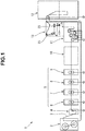
Fig. 1 is a side view of a web offset printing press including a lighting device and an inspection device according to the present invention; -
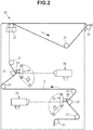
Fig. 2 is an enlarged side view of a part of the printing press; -
Fig. 3 is a plan view showing a color bar; -
Fig. 4 is a rear view showing the lighting device viewed from a camera side; -
Fig. 5 is a side view of the lighting device; -
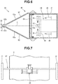
Fig. 6 is a sectional view of the lighting device taken along a line VI - VI inFig. 4 ; -
Fig. 7 is a plan view of a camera; -
Fig. 8 is a block diagram showing the configuration of the inspection device; -
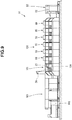
Fig. 9 is a side view of a sheet-fed offset printing press according to another embodiment; -
Fig. 10 is an enlarged side view showing the main part of the sheet-fed offset printing press; and -
Fig. 11 is a side view of a sheet-fed offset printing press according to still another embodiment. Best Mode for Carrying Out the Invention - A lighting device and an inspection device according to the present invention will now be described in detail with reference to
Figs. 1 to 8 . In this embodiment, an example in which the present invention is applied to a web offset printing press is shown. - A web offset printing press 1 shown in
Fig. 1 includes aweb supply unit 2 on the leftmost side inFig. 1 , and sends aweb 3 from theweb supply unit 2 to the right side inFig. 1 . Aninfield unit 4 is provided on the right side of theweb supply unit 2, and aprinting section 5 is provided on the right side of theinfield unit 4. Theprinting section 5 performs printing on both the obverse and reverse surfaces of theweb 3 by first tofourth printing units 6 to 9. On the downstream side of theprinting section 5 along the conveyance direction of theweb 3, adrying unit 10, acooling unit 11, and afolding machine 12 are arranged in this order. Aweb path unit 13 is provided on the upper side of thecooling unit 11. Theweb 3 is sent from theweb path unit 13 to thefolding machine 12. - As shown in
Fig. 2 , theweb path unit 13 employs a structure configured to send theweb 3 wound around a plurality ofrollers 21 to the upper side. In the lower portion of theweb path unit 13, twolighting devices 23 and twocameras 24, which form a part of an inspection device 22 (seeFig. 8 ) according to the present invention, are provided. Thelighting devices 23 and thecameras 24 are arranged at two points apart in the vertical direction in theweb path unit 13. Thelighting device 23 on the lower side irradiates the obverse surface of theweb 3 advancing upward in theweb path unit 13 with light obliquely from above. Thelighting device 23 on the upper side irradiates the reverse surface of theweb 3 advancing upward in theweb path unit 13 with light obliquely from above. - The
camera 24 on the lower side captures, from the horizontal direction, theweb 3 irradiated with light by thelighting device 23 on the lower side, and sends image data to a control device 25 (seeFig. 8 ) to be described later. The configuration of thecontrol device 25 will be described later. Thecamera 24 on the upper side captures, from the horizontal direction, theweb 3 irradiated with light by thelighting device 23 on the upper side, and sends image data to thecontrol device 25. Each of thecameras 24 is formed by a line camera and can simultaneously capture theweb 3 from one end to the other end in the widthwise direction. - The
camera 24 according to this embodiment captures acolor bar 26 provided in a margin portion near a printedportion 3a of theweb 3, as shown inFig. 3. Fig. 3 shows an end portion of theweb 3 that has been cut off. Thecolor bar 26 extends in a predetermined width D1 from one end portion to the other end portion of theweb 3 in the widthwise direction (the left-and-right direction inFig. 3 ), and is formed by a number ofcolor patches 26a arranged in the widthwise direction. Eachcolor patch 26a is printed such that a predetermined density of, for example, 100% can be obtained as a color density by the first tofourth printing units 6 to 9. - As shown in
Fig. 4 , thelighting device 23 is formed into an elongated shape extending from one end side to the other end side of theweb 3 in the widthwise direction (the left-and-right direction inFig. 4 ) when viewed from the camera side, and its two end portions in the longitudinal direction are attached to a pair offrames support frame 33. Thesupport frame 33 is stretched between the pair offrames frames support shafts 34. Thesupport shafts 34 are connected to the lower end portion of thesupport frame 33. Hence, as shown inFig. 5 , thesupport frame 33 can swing between a use position indicated by a solid line inFig. 5 and a retreat position indicated by an alternate long and two short dashed line inFig. 5 . - Each of the
frames upper stopper 35 and alower stopper 36 to define the position of thesupport frame 33. Theupper stopper 35 regulates falling of the support frame from the use position to the side of theweb 3. Lock pins 38 that detachably engage with engaging members 37 (seeFig. 4 ) of theframes support frame 33 at the use position. When the lock pins 38 are inserted into and engage with the engagingmembers 37, thesupport frame 33 is held at the use position. When the lock pins 38 are removed from the engagingmembers 37 and disengaged, thesupport frame 33 can swing from the use position to the retreat position. Thesupport frame 33 according to this embodiment includeshandles 39 to be held by both hands of an operator (not shown) at the time of swing. - The
lower stopper 36 supports, from the lower side, thesupport frame 33 that has swung to the retreat position, and regulates downward swing of thesupport frame 33 from the retreat position. - As shown in
Fig. 6 , thelighting device 23 is equipped with a box-shapedhousing 41 with an opening on one of its sides, alight shielding member 42 attached to the opening of thehousing 41, alight emitting device 44 including alight source 43 and stored in thehousing 41, and the like. - As shown in
Fig. 4 , thehousing 41 is formed long in the widthwise direction of theweb 3. In the longitudinal direction of theweb 3, the length of thehousing 41 is longer than the width of theweb 3. The two end portions of thehousing 41 in the longitudinal direction are attached to thesupport frame 33 via brackets 45 (seeFig. 5 ). Thehousing 41 is attached to thebracket 45 by threadably engaging a plurality ofattachment bolts 46 extending through thebracket 45 with thehousing 41, as shown inFig. 5 . In this embodiment, arc-shapedlong holes 47 configured to pass theattachment bolts 46 are formed in thebracket 45 such that the attachment angle of thehousing 41 can be changed. - As shown in
Fig. 6 , thelight shielding member 42 includes, at its end portion facing theweb 3, anirradiation port 61 that opens linearly in the widthwise direction of theweb 3. Thelight shielding member 42 according to this embodiment includes afirst plate member 62 attached to the upper portion of thehousing 41 inFig. 6 , and asecond plate member 63 attached to the lower portion of thehousing 41 inFig. 6 . - The pair of first and
second plate members second plate members housing 41 in the widthwise direction of theweb 3. - Also, the first and
second plate members portions plate members light source 43 toward theirradiation port 61, and first and secondparallel portions portions light emitting device 44. - The
irradiation port 61 is formed between the firstparallel portion 62b and the secondparallel portion 63b, where thefirst plate member 62 and thesecond plate member 63 parallelly face each other. - The space between the first
parallel portion 62b and the secondparallel portion 63b, that is, an opening width D2 of theirradiation port 61 in a direction orthogonal to the widthwise direction of theweb 3 is narrower than the width D1 (seeFig. 3 ) of thecolor bar 26 in the direction orthogonal to the widthwise direction of theweb 3. Hence, linear light narrower than the width D1 of thecolor bar 26 exits from theirradiation port 61. - The
light emitting device 44 includes thelight source 43, alens 64 located on a side of the opening of thehousing 41, andair blast members 65 located near thelight source 43. - The
light source 43 is formed by a number ofLEDs 43a. TheLEDs 43a are mounted on asubstrate 66 such that the optical axis C is perpendicular to thesubstrate 66, and are provided while being arranged at a predetermined interval in the whole region in the longitudinal direction of thehousing 41. - The
lens 64 is configured to diffuse light from thelight source 43 to the whole region in thelight shielding member 42. Some of the light diffused by thelens 64 directly travels toward theirradiation port 61, and most of the remaining light is reflected by the first and second reflectingportions irradiation port 61. For this reason, from theirradiation port 61, the light exits in a direction parallel or almost parallel to the optical axis C, and theweb 3 is irradiated with linear light having a narrow width in the direction orthogonal to the widthwise direction. - The
air blast members 65 blast air sent from an air supply source (not shown). Theair blast members 65 are arranged on both sides of theLEDs 43a and supported by thehousing 41 such that the air is blasted to theLEDs 43a. When the air is blasted to theLEDs 43a, theLEDs 43a are cooled. Note that theair blast members 65 may be arranged to blast air to the back surface of thesubstrate 66, as indicated by long and two short dashed lines inFig. 6 . - Since the air blasted from the
air blast members 65 passes inside thelight shielding member 42 and is discharged from theirradiation port 61 to the outside of thelighting device 23, the air is blasted from theirradiation port 61. The air always flows near theirradiation port 61. This prevents powder dust generated from theweb 3 or ink mist generated in the first tofourth printing units 6 to 9 from entering thelight shielding member 42 via theirradiation port 61, and adhering to thelens 64 or thelight source 43 or adhering to the distal end portion of theirradiation port 61 and closing theirradiation port 61. - As shown in
Fig. 7 , thecamera 24 is attached to asupport member 67 stretched between the pair offrames web 3 in the widthwise direction. - As shown in
Fig. 8 , theinspection device 22 includes a part of thecontrol device 25 configured to control the operation of the printing press 1, the above-describedlighting device 23 and thecamera 24, amobile densitometer 71 to be described later, adisplay device 72, and the like. Themobile densitometer 71 reads thecolor bar 26 serving as the reference of theweb 3 cut for each printedportion 3a (seeFig. 3 ) by a dedicated image reader (not shown), and measures the density of eachcolor patch 26a from image data obtained by the image reader. The measurement result is sent as a reference density value to thecontrol device 25. Thedisplay device 72 displays the operation state of the printing press 1, various kinds of alarms, and the like. - The
control device 25 includes aprinting section 73, aninspection section 74, astorage unit 75, and adetermination unit 76. Theprinting section 73 controls the operations of the drive motor (not shown) and various kinds of actuators of the printing press 1. - The
inspection section 74 includes alighting section 81, animaging unit 82, anacquisition unit 83, acalculation unit 84, and atype detection unit 85. - The
lighting section 81 switches ON/OFF of thelight source 43. Theimaging unit 82 includes thecamera 24, a circuit (not shown) configured to control the image capturing operation of thecamera 24, and the like, and captures thecolor bar 26 by thecamera 24 during conveyance of theweb 3. - The
acquisition unit 83 acquires the color measurement value (RGB value) of the image data captured by thecamera 24. The image data is image data of eachcolor patch 26a of thecolor bar 26. - The
calculation unit 84 performs calculation using aconversion formula 86 prepared in advance and acorrection value 87 stored in thestorage unit 75. Theconversion formula 86 is an equation for calculating the reference density value measured by themobile densitometer 71 from a reference color measurement value obtained by capturing, by thecamera 24, thecolor bar 26 similar to thereference color bar 26 measured by themobile densitometer 71. As theconversion formula 86, an equation similar to an equation described in, for example,Japanese Patent Laid-Open No. 2013-75519 conversion formula 86 is used, a density value can be converted from the color measurement value obtained by capturing thecolor bar 26 that is not a reference. The density value obtained by the calculation will be referred to as a "converted density value" hereinafter. - The
correction value 87 is determined for each type of theweb 3. If the type of theweb 3 changes, even if printing is performed in the same density, the density value changes from the converted density value based on the color measurement value obtained by image capturing by thecamera 24. Thecorrection value 87 is a value used to correct a calculation result that changes due to the type of theweb 3. That is, when thecalculation unit 84 performs calculation using the color measurement value of actual image data obtained by image capturing using thecamera 24 and the above-describedconversion formula 86 and thecorrection value 87, a corrected converted density value corrected by thecorrection value 87 is obtained. - The data of the type of the
web 3 is included in basic data to be used by theprinting section 73 to control a printing operation. Thetype detection unit 85 reads out the data of the type of theweb 3 from the basic data. - The
storage unit 75 stores the above-describedcorrection value 87 for each type of theweb 3 as a correction processing table. - The
determination unit 76 compares the corrected converted density value with a predetermined reference density value (determination criterion value) serving as a predetermined determination criterion for eachcolor patch 26a. If the difference between the values falls within an allowable range, it is determined that the quality is high. If the difference falls outside the allowable range, it is determined that the quality is poor. Thedetermination unit 76 displays the quality determination result on thedisplay device 72. - In the printing press 1 including the thus configured
inspection device 22, when printing is performed on theweb 3, thecolor bar 26 is captured by thecamera 24 in theweb path unit 13, and thedetermination unit 76 determines the quality of the ink density based on image data obtained by the image capturing. - The quality determination is performed by the
determination unit 76 by comparing the corrected converted density value obtained by thecalculation unit 84 using the color measurement value of the actual image data obtained by image capturing using thecamera 24, theconversion formula 86, and thecorrection value 87 corresponding to the type of thecurrent web 3 with the reference density value serving as the determination criterion. - The color measurement value of the actual image data obtained by image capturing using the
camera 24 does not change even if the pattern printed on theweb 3 changes, if the ink supply amounts in the first tofourth printing units 6 to 9 do not change. This is because thelighting device 23 irradiates thecolor bar 26 on theweb 3 with linear light, and only thecolor bar 26 can be irradiated with the light of thelighting device 23. For this reason, thecolor bar 26 can be captured by thecamera 24 without any influence of the pattern on the periphery of thecolor bar 26, and the image data of thecolor bar 26 in original colors can be obtained by the image capturing. - That the color measurement value of the image data captured using the
camera 24 does not change even if the pattern changes means that it is unnecessary to perform conversion formula re-obtainment that is performed in the conventional device. Hence, according to this embodiment, since the conversion formula re-obtainment need not be performed at the time of print job switching, it is possible to provide a lighting device capable of raising efficiency when switching the print job. - The
irradiation port 61 according to this embodiment is formed between the firstparallel portion 62b and the secondparallel portion 63b, where thefirst plate member 62 and thesecond plate member 63 parallelly face each other. For this reason, since light that is not parallel or almost parallel to the optical axis C is shielded by thefirst plate member 62 and thesecond plate member 63, thecolor bar 26 is substantially irradiated with parallel light. - As a result, only the color bar portion is irradiated with the light of the
lighting device 23, and image data is never influenced by diffused light from the pattern on the periphery of thecolor bar 26. Hence, accurate density measurement can be performed, and the frequency of re-obtaining the conversion formula can be reduced. It is therefore possible to prevent theweb 3 from being wasted and save the work time needed for preparation until actual printing. - The
lighting device 23 according to this embodiment includes theair blast members 65. It is therefore possible to prevent dirt such as ink mist or powder dust from adhering to thelens 64, thelight source 43, or theirradiation port 61 and reduce the maintenance frequency, and it is also possible to maintain high inspection performance and density measurement performance. - Also, since the
lighting device 23 includes theair blast members 65, it is possible to suppress a brightness change by cooling the light source 43 (LEDs 43a) with cooling air. - The
first plate member 62 and thesecond plate member 63 according to this embodiment include the first and second reflectingportions plate members light source 43 toward theirradiation port 61. - For this reason, since the
color bar 26 can be irradiated with strong (bright) light from theirradiation port 61, the brightness difference between thecolor bar 26 and the pattern on the periphery becomes large, and the image data is more hardly influenced by the pattern on the periphery in image capturing. Hence, a density value close to the reference density value measured by themobile densitometer 71 can be obtained using thecamera 24, and the reliability of the determination result by thedetermination unit 76 becomes higher. - The opening width D2 of the
irradiation port 61 according to this embodiment in the direction orthogonal to the widthwise direction of theweb 3 is narrower than the width D1 of thecolor bar 26 in the direction orthogonal to the widthwise direction of theweb 3. According to thelighting device 23, only thecolor bar 26 is irradiated, and a stable slit light source is generated. Hence, the accuracy of density quality determination becomes higher. - In the
inspection device 22 according to this embodiment, if the print job changes, and the type of theweb 3 changes, thetype detection unit 85 detects the type of thenew web 3. Then, thecalculation unit 84 obtains a corrected converted density value corresponding to thenew web 3 using thecorrection value 87 according to the type of theweb 3, a color measurement value obtained by capturing, using thecamera 24, thecolor bar 26 printed on thenew web 3, and theconversion formula 86. - Hence, according to this embodiment, density measurement can be performed without correction processing not only in a case in which the printing material (web 3) does not change, and only the pattern changes but also in a case in which the printing material changes.
- A lighting device can be configured as shown in
Figs. 9 and10 . The same reference numerals as inFigs. 1 to 8 denote the same or similar members inFigs. 9 and10 , and a detailed description thereof will appropriately be omitted. - A
printing press 91 shown inFig. 9 is a sheet-fed offset printing press, and asheet supply unit 93 configured to supply asheet 92 is provided at an end portion on the right side inFig. 9 . Theprinting press 91 includes aprinting section 100 including first tosixth printing units 94 to 99, acoating unit 101 located on the downstream side of theprinting section 100 along the conveyance direction of thesheet 92, and asheet discharge unit 103 configured to dry thesheet 92 coated by thecoating unit 101 and discharge it to adischarge pile 102. The first tosixth printing units 94 to 99 perform printing on one surface of thesheet 92. - In this embodiment, a
lighting device 23 according to the present invention is arranged at a position facing animpression cylinder 104 in thecoating unit 101. As shown inFig. 10 , thelighting device 23 according to this embodiment is arranged immediately above theimpression cylinder 104, and irradiates the upper surface (printed surface) of thesheet 92 conveyed by theimpression cylinder 104 with linear light. Acamera 24 is provided at a position apart upward from theimpression cylinder 104. - In this embodiment, a
color bar 26 on thesheet 92 can be captured by thecamera 24 without any influence of a pattern on the periphery. Hence, according to this embodiment, efficiency when switching the print job of the sheet-fed offsetprinting press 91 becomes higher. - A lighting device can be configured as shown in
Fig. 11 . The same reference numerals as inFigs. 1 to 8 denote the same or similar members inFig. 11 , and a detailed description thereof will appropriately be omitted. - A
printing press 111 shown inFig. 11 is a sheet-fed offset printing press, and asheet supply unit 113 configured to supply asheet 112 is provided at an end portion on the right side inFig. 11 . Theprinting press 111 includes aprinting section 114 configured to perform double-sided printing, aninspection section 115 provided on the downstream side of theprinting section 114 along the conveyance direction of thesheet 112, and asheet discharge unit 120 configured to send thesheet 112 inspected by theinspection section 115 by a chain-type conveyance device 116 and discharge it to a plurality ofdelivery piles 117 to 119. - The
printing section 114 includes first to fifthsurface printing units 121 to 125 configured to perform printing on the obverse surface of thesheet 112, and first to fifthback printing units 126 to 130 configured to perform printing on the reverse surface of thesheet 112. - The
inspection section 115 includes an upstream-sidesurface inspection unit 131 and an upstream-side backinspection unit 132, and a downstream-sidesurface inspection unit 133 and a downstream-side backinspection unit 134. - The upstream-side
surface inspection unit 131 and the upstream-side backinspection unit 132 perform inspection of the printing quality of thesheet 112 and density inspection of acolor bar 26 usingvisible light cameras 135. In this embodiment, alighting device 23 according to the present invention irradiates thesheet 112 to be captured by the visiblelight camera 135 with linear light. The visiblelight camera 135 is the same as thecamera 24 used when employing the first embodiment. - The downstream-side
surface inspection unit 133 and the downstream-side backinspection unit 134 perform inspection of the printing quality of thesheet 112 usingultraviolet cameras 136. - According to this embodiment, it is possible to perform ink density inspection on both the obverse surface and the reverse surface of the
sheet 112. In addition, since thecolor bar 26 can be captured by the visiblelight camera 135 without any influence of a pattern on the periphery of thecolor bar 26, efficiency when switching the print job of the sheet-fed offsetprinting press 111 becomes higher. - In the above-described embodiments, an example in which the lighting device according to the present invention is used in a density inspection device configured to capture a color bar and inspect the density of ink has been described. However, the lighting device according to the present invention is not limited to this example, and may be used in a pattern inspection device configured to inspect the presence/absence of a printing failure such as printing omission or dirt adhesion in a printed pattern portion. Even in this case, a linear narrow region serving as an inspection region is irradiated with light, thereby emphasizing the inspection region without any influence of a pattern in a non-inspection region and detecting a printing failure accurately as compared to conventional inspection that irradiates a wide range with light.
- 3...web, 23...lighting device, 43...light source, 61...irradiation port, 62...first plate member, 62b...first parallel portion, 63...second plate member, 63b...second parallel portion, 92, 112...sheet
Claims (6)
- A lighting device configured to irradiate one of a sheet and a web under conveyance with light, comprising:a light source; andan irradiation port which opens linearly in a widthwise direction of one of the sheet and the web at an end portion facing one of the sheet and the web,wherein the irradiation port is formed between parallel portions where a first plate member and a second plate member parallelly face each other, andone of the sheet and the web under conveyance is irradiated with linear light.
- The lighting device according to claim 1, further comprising an air blast member for supplying cooling air to the light source.
- The lighting device according to claim 1 or 2, wherein the first plate member and the second plate member include reflecting portions that are inclined such that a space between the plate members gradually becomes narrower from a side of the light source toward the irradiation port.
- The lighting device according to any one of claims 1 to 3, wherein a color bar is printed on one of the sheet and the web, and the color bar is irradiated with the linear light.
- The lighting device according to claim 4, wherein an opening width of the irradiation port in a direction orthogonal to the widthwise direction of one of the sheet and the web is narrower than a width of the color bar in the direction orthogonal to the widthwise direction of one of the sheet and the web.
- An inspection device comprising:a lighting device according to claim 4 or 5;an imaging unit configured to capture a color bar printed on one of a sheet and a web in a state in which the color bar is irradiated with light of the lighting device during conveyance of one of the sheet and the web;a type detection unit configured to detect a type of one of the sheet and the web;an acquisition unit configured to acquire a color measurement value of image data captured by the imaging unit;a storage unit configured to store a correction value for each type of one of the sheet and the web;a calculation unit configured to read out, from the storage unit, the correction value corresponding to the type of one of the sheet and the web detected by the type detection unit and calculate a density value of the color bar using the correction value and the color measurement value acquired by the acquisition unit; anda determination unit configured to determine quality by comparing the density value with a determination criterion value.
Applications Claiming Priority (2)
| Application Number | Priority Date | Filing Date | Title |
|---|---|---|---|
| JP2019021242 | 2019-02-08 | ||
| PCT/JP2020/004799 WO2020162593A1 (en) | 2019-02-08 | 2020-02-07 | Lighting device and inspection device |
Publications (2)
| Publication Number | Publication Date |
|---|---|
| EP3922984A1 true EP3922984A1 (en) | 2021-12-15 |
| EP3922984A4 EP3922984A4 (en) | 2022-11-02 |
Family
ID=71948345
Family Applications (1)
| Application Number | Title | Priority Date | Filing Date |
|---|---|---|---|
| EP20753103.9A Pending EP3922984A4 (en) | 2019-02-08 | 2020-02-07 | LIGHTING DEVICE AND INSPECTION DEVICE |
Country Status (5)
| Country | Link |
|---|---|
| US (2) | US11677893B2 (en) |
| EP (1) | EP3922984A4 (en) |
| JP (2) | JP7273863B2 (en) |
| CN (1) | CN113424054B (en) |
| WO (1) | WO2020162593A1 (en) |
Families Citing this family (1)
| Publication number | Priority date | Publication date | Assignee | Title |
|---|---|---|---|---|
| US11677893B2 (en) | 2019-02-08 | 2023-06-13 | Komori Corporation | Lighting device and inspection device with light irradiation port configured to discharge cooling air |
Family Cites Families (60)
| Publication number | Priority date | Publication date | Assignee | Title |
|---|---|---|---|---|
| JPS5040022A (en) * | 1973-08-15 | 1975-04-12 | ||
| JPS5068583U (en) * | 1973-10-22 | 1975-06-18 | ||
| US4003660A (en) | 1975-12-03 | 1977-01-18 | Hunter Associates Laboratory, Inc. | Sensing head assembly for multi-color printing press on-line densitometer |
| JPS59128418A (en) | 1983-01-13 | 1984-07-24 | Toppan Printing Co Ltd | Printed material inspecting device |
| JPH0540022A (en) * | 1991-08-07 | 1993-02-19 | Iwaki Electron Corp Ltd | Optical lighting device for appearance inspection |
| US5215370A (en) * | 1991-11-25 | 1993-06-01 | Eastman Kodak Company | Linear light source |
| JP3230850B2 (en) | 1992-09-09 | 2001-11-19 | 株式会社リコー | Image reading device |
| JP3117368B2 (en) * | 1994-08-04 | 2000-12-11 | 三菱重工業株式会社 | Scan monitoring device |
| JPH0969960A (en) * | 1995-09-01 | 1997-03-11 | Brother Ind Ltd | Print output device |
| DE19536770A1 (en) * | 1995-10-02 | 1997-04-03 | R A M Gmbh | Method for inspecting foils |
| DE29606613U1 (en) * | 1996-04-11 | 1996-06-13 | Akzo Nobel N.V., Arnheim/Arnhem | Device for the continuous detection of intermingling points in multifilament yarns |
| US5791249A (en) * | 1997-03-27 | 1998-08-11 | Quad/Tech, Inc. | System and method for regulating dampening fluid in a printing press |
| JP3659770B2 (en) * | 1997-05-21 | 2005-06-15 | 株式会社リコー | Line light generator |
| US6275600B1 (en) * | 1998-03-09 | 2001-08-14 | I.Data International, Inc. | Measuring image characteristics of output from a digital printer |
| JP4038930B2 (en) * | 1999-03-31 | 2008-01-30 | ブラザー工業株式会社 | Color measuring device |
| US6803937B2 (en) * | 2000-05-23 | 2004-10-12 | Noritsu Koki Co., Ltd. | Photographic printer having varied intensities or optical modulation data for laser light sources |
| JP4428855B2 (en) * | 2000-12-12 | 2010-03-10 | キヤノン株式会社 | Image forming apparatus |
| US7349132B2 (en) * | 2003-01-30 | 2008-03-25 | Kabushiki Kaisha Toshiba | Image reading apparatus |
| JP2004328473A (en) * | 2003-04-25 | 2004-11-18 | Fuji Photo Film Co Ltd | Sheet for color calibration, color calibration method, and image recorder |
| CN1778561A (en) * | 2004-11-18 | 2006-05-31 | 诚研科技股份有限公司 | Printing device that can judge the remaining status of the ribbon |
| JP4895357B2 (en) * | 2006-03-31 | 2012-03-14 | キヤノン株式会社 | Image forming apparatus and image forming method |
| JP2008198478A (en) * | 2007-02-13 | 2008-08-28 | Daiwa Light Kogyo:Kk | LED lighting device |
| JP2008229874A (en) * | 2007-03-16 | 2008-10-02 | Dainippon Screen Mfg Co Ltd | Printing equipment |
| JP2009034831A (en) * | 2007-07-31 | 2009-02-19 | Ushio Inc | Light irradiator and printer using this light irradiator |
| JP2009125977A (en) * | 2007-11-20 | 2009-06-11 | Ushio Inc | Light irradiator |
| JP2009285909A (en) | 2008-05-28 | 2009-12-10 | Komori Corp | Sheet-like matter monitor for perfector |
| JP5129026B2 (en) | 2008-05-28 | 2013-01-23 | 株式会社小森コーポレーション | Sheet material monitoring device for sheet material conveying device |
| JP2010000735A (en) * | 2008-06-23 | 2010-01-07 | Mimaki Engineering Co Ltd | Ultraviolet curing-type inkjet printer and light source unit for ultraviolet curing-type inkjet printer |
| US7946735B2 (en) | 2008-08-22 | 2011-05-24 | Joseph Chou | LED lighting apparatus having heat dissipating frame |
| JP5538925B2 (en) * | 2009-02-13 | 2014-07-02 | キヤノン株式会社 | Image processing apparatus and image processing method |
| JP2011005726A (en) | 2009-06-25 | 2011-01-13 | Ushio Inc | Light radiating device |
| CN101696969B (en) * | 2009-11-02 | 2013-01-23 | 天津科技大学 | Gray technology based comprehensive quality evaluation method of high-gloss inkjet paper |
| JP5531745B2 (en) * | 2010-04-14 | 2014-06-25 | コニカミノルタ株式会社 | Image forming apparatus |
| JP2012069395A (en) | 2010-09-24 | 2012-04-05 | Citizen Holdings Co Ltd | Lighting device |
| JP5640729B2 (en) * | 2010-12-22 | 2014-12-17 | コニカミノルタ株式会社 | Image forming apparatus |
| JP5716156B2 (en) * | 2011-03-31 | 2015-05-13 | 株式会社オプトデザイン | Linear light source device using point light source and illumination device for optical reader using the same |
| JP5205498B2 (en) | 2011-08-08 | 2013-06-05 | 株式会社ジャパンディスプレイイースト | Light irradiation device |
| JP2013075519A (en) * | 2011-09-13 | 2013-04-25 | Komori Corp | Control device of printer and control method |
| JP5783194B2 (en) | 2012-03-19 | 2015-09-24 | 株式会社リコー | Imaging unit, color measuring device, image forming apparatus, color measuring system, and color measuring method |
| JP6164832B2 (en) * | 2012-12-19 | 2017-07-19 | 株式会社小糸製作所 | Light guide and lighting device |
| TWI498222B (en) * | 2013-01-11 | 2015-09-01 | Dinkle Entpr Co Ltd | Method and device to inspect quality of printings |
| JP6197318B2 (en) * | 2013-03-15 | 2017-09-20 | 株式会社リコー | Spectral characteristic measurement method, spectral characteristic measurement apparatus, image evaluation apparatus, and image forming apparatus |
| US9407776B2 (en) * | 2013-08-13 | 2016-08-02 | Technology Watch, LLC | Method for evaluation of printing and imaging systems that grade attributes of an image evaluation document produced by such systems |
| CN106132709B (en) * | 2014-03-21 | 2021-08-31 | 博斯特佛罗伦萨有限公司 | Method and apparatus for controlling and managing printing parameters of a flexographic printing press |
| US10083364B2 (en) | 2014-04-16 | 2018-09-25 | Glory Ltd. | Method and apparatus for removing character background from colored image |
| JP6333765B2 (en) | 2015-04-08 | 2018-05-30 | 富士フイルム株式会社 | Inkjet recording device |
| JP2016014669A (en) * | 2015-07-21 | 2016-01-28 | 株式会社アイテックシステム | Lighting device for use with apparatus for inspecting surface of long object using line sensor camera |
| JP2017177495A (en) | 2016-03-30 | 2017-10-05 | 大日本印刷株式会社 | Printed matter inspection method and apparatus |
| JP2017207427A (en) | 2016-05-20 | 2017-11-24 | セイコーエプソン株式会社 | Measuring device and printing device |
| CN106770340B (en) * | 2016-12-13 | 2021-02-26 | 北京印刷学院 | Printing quality detection device |
| JP6907630B2 (en) * | 2017-03-21 | 2021-07-21 | 株式会社リコー | Image forming apparatus, image forming system and calibration method |
| JP6969144B2 (en) * | 2017-04-14 | 2021-11-24 | セイコーエプソン株式会社 | Printing device and control method |
| JP7124330B2 (en) * | 2018-02-14 | 2022-08-24 | コニカミノルタ株式会社 | IMAGE FORMING APPARATUS AND IMAGE FORMING APPARATUS CONTROL METHOD |
| WO2020067158A1 (en) * | 2018-09-27 | 2020-04-02 | 京セラ株式会社 | Photoirradiation device and printing device |
| US11677893B2 (en) * | 2019-02-08 | 2023-06-13 | Komori Corporation | Lighting device and inspection device with light irradiation port configured to discharge cooling air |
| JP7379147B2 (en) * | 2019-12-25 | 2023-11-14 | キヤノン株式会社 | Image forming device, image forming method, and program |
| JP7451253B2 (en) * | 2020-03-23 | 2024-03-18 | キヤノン株式会社 | Image forming device and information processing method |
| JP7500305B2 (en) * | 2020-06-24 | 2024-06-17 | キヤノン株式会社 | Printing device, control method thereof, and program |
| JP7520636B2 (en) * | 2020-08-13 | 2024-07-23 | キヤノン株式会社 | Image forming apparatus, control method thereof, and program |
| JP7610393B2 (en) * | 2020-11-02 | 2025-01-08 | キヤノン株式会社 | Image forming device |
-
2020
- 2020-02-07 US US17/310,505 patent/US11677893B2/en active Active
- 2020-02-07 CN CN202080013406.7A patent/CN113424054B/en active Active
- 2020-02-07 JP JP2020571288A patent/JP7273863B2/en active Active
- 2020-02-07 EP EP20753103.9A patent/EP3922984A4/en active Pending
- 2020-02-07 WO PCT/JP2020/004799 patent/WO2020162593A1/en not_active Ceased
-
2023
- 2023-03-17 JP JP2023042913A patent/JP7490846B2/en active Active
- 2023-04-28 US US18/309,091 patent/US12003689B2/en active Active
Also Published As
| Publication number | Publication date |
|---|---|
| JP2023082029A (en) | 2023-06-13 |
| JPWO2020162593A1 (en) | 2021-11-25 |
| US12003689B2 (en) | 2024-06-04 |
| WO2020162593A1 (en) | 2020-08-13 |
| JP7273863B2 (en) | 2023-05-15 |
| EP3922984A4 (en) | 2022-11-02 |
| US11677893B2 (en) | 2023-06-13 |
| US20230283738A1 (en) | 2023-09-07 |
| JP7490846B2 (en) | 2024-05-27 |
| US20220038605A1 (en) | 2022-02-03 |
| CN113424054B (en) | 2025-01-10 |
| CN113424054A (en) | 2021-09-21 |
Similar Documents
| Publication | Publication Date | Title |
|---|---|---|
| JP5264166B2 (en) | Inline measurement and adjustment on the press | |
| JP4856628B2 (en) | Device for in-line monitoring of print quality in a sheet-fed offset press | |
| US7884926B2 (en) | Color measuring apparatus having differently operating measuring devices | |
| JP3288628B2 (en) | System and method for adjusting dampening fluid in a printing press | |
| US12003689B2 (en) | Lighting device and inspection device with light shield irradiation port configured to irradiate light only on the inspection region | |
| EP2646250A1 (en) | In line color monitoring system | |
| US5543922A (en) | Method and apparatus for on-press color measurement | |
| US11167544B2 (en) | Screen printer | |
| US7550745B2 (en) | Sensing device | |
| EP1551635B1 (en) | Method and apparatus for on-line monitoring print quality | |
| TWI534011B (en) | Printing screen and method for adjusting the relative position of a printing pattern and a substrate | |
| JP5371644B2 (en) | Strength-optimized control mark measurement | |
| JP2005231360A (en) | Device and method for recognizing and evaluating image from prescribed part of printed matter | |
| JP2011073421A (en) | Print inspection device | |
| US9531936B2 (en) | Camera system, colour measuring system, and offset printing press | |
| JPS61195844A (en) | Printing status checking device | |
| JPH0422143B2 (en) | ||
| JP2001162773A (en) | Print inspection equipment | |
| JP2009098362A (en) | Photo print processing device |
Legal Events
| Date | Code | Title | Description |
|---|---|---|---|
| STAA | Information on the status of an ep patent application or granted ep patent |
Free format text: STATUS: THE INTERNATIONAL PUBLICATION HAS BEEN MADE |
|
| PUAI | Public reference made under article 153(3) epc to a published international application that has entered the european phase |
Free format text: ORIGINAL CODE: 0009012 |
|
| STAA | Information on the status of an ep patent application or granted ep patent |
Free format text: STATUS: REQUEST FOR EXAMINATION WAS MADE |
|
| 17P | Request for examination filed |
Effective date: 20210809 |
|
| AK | Designated contracting states |
Kind code of ref document: A1 Designated state(s): AL AT BE BG CH CY CZ DE DK EE ES FI FR GB GR HR HU IE IS IT LI LT LU LV MC MK MT NL NO PL PT RO RS SE SI SK SM TR |
|
| DAV | Request for validation of the european patent (deleted) | ||
| DAX | Request for extension of the european patent (deleted) | ||
| REG | Reference to a national code |
Ref country code: DE Ref legal event code: R079 Free format text: PREVIOUS MAIN CLASS: G01N0021840000 Ipc: B41F0033000000 |
|
| A4 | Supplementary search report drawn up and despatched |
Effective date: 20221006 |
|
| RIC1 | Information provided on ipc code assigned before grant |
Ipc: G01B 11/25 20060101ALI20220929BHEP Ipc: G01N 21/89 20060101ALI20220929BHEP Ipc: G01N 21/86 20060101ALI20220929BHEP Ipc: B41F 33/00 20060101AFI20220929BHEP |
|
| STAA | Information on the status of an ep patent application or granted ep patent |
Free format text: STATUS: EXAMINATION IS IN PROGRESS |
|
| 17Q | First examination report despatched |
Effective date: 20260211 |