JP2017207427A - Measurement device and printer - Google Patents
Measurement device and printer Download PDFInfo
- Publication number
- JP2017207427A JP2017207427A JP2016101385A JP2016101385A JP2017207427A JP 2017207427 A JP2017207427 A JP 2017207427A JP 2016101385 A JP2016101385 A JP 2016101385A JP 2016101385 A JP2016101385 A JP 2016101385A JP 2017207427 A JP2017207427 A JP 2017207427A
- Authority
- JP
- Japan
- Prior art keywords
- measurement
- light
- illumination
- center
- measured
- Prior art date
- Legal status (The legal status is an assumption and is not a legal conclusion. Google has not performed a legal analysis and makes no representation as to the accuracy of the status listed.)
- Pending
Links
- 238000005259 measurement Methods 0.000 title claims abstract description 397
- 238000005286 illumination Methods 0.000 claims abstract description 181
- 230000003287 optical effect Effects 0.000 claims abstract description 87
- 230000007246 mechanism Effects 0.000 claims description 8
- 230000032258 transport Effects 0.000 description 23
- 238000000034 method Methods 0.000 description 21
- 238000012937 correction Methods 0.000 description 17
- 238000010586 diagram Methods 0.000 description 17
- 230000008569 process Effects 0.000 description 14
- 238000004737 colorimetric analysis Methods 0.000 description 13
- 230000007423 decrease Effects 0.000 description 12
- 238000012545 processing Methods 0.000 description 12
- 239000000758 substrate Substances 0.000 description 11
- 238000000691 measurement method Methods 0.000 description 10
- 230000008859 change Effects 0.000 description 8
- 238000013459 approach Methods 0.000 description 7
- 230000015572 biosynthetic process Effects 0.000 description 6
- 230000003595 spectral effect Effects 0.000 description 5
- 230000009467 reduction Effects 0.000 description 4
- 230000005540 biological transmission Effects 0.000 description 3
- 238000006073 displacement reaction Methods 0.000 description 3
- 230000000694 effects Effects 0.000 description 3
- 230000006870 function Effects 0.000 description 3
- 239000011521 glass Substances 0.000 description 3
- 230000004308 accommodation Effects 0.000 description 2
- 229910045601 alloy Inorganic materials 0.000 description 2
- 239000000956 alloy Substances 0.000 description 2
- 239000003086 colorant Substances 0.000 description 2
- 238000001514 detection method Methods 0.000 description 2
- 238000007689 inspection Methods 0.000 description 2
- 239000002184 metal Substances 0.000 description 2
- 230000004048 modification Effects 0.000 description 2
- 238000012986 modification Methods 0.000 description 2
- 229910001316 Ag alloy Inorganic materials 0.000 description 1
- 230000009471 action Effects 0.000 description 1
- BJQHLKABXJIVAM-UHFFFAOYSA-N bis(2-ethylhexyl) phthalate Chemical compound CCCCC(CC)COC(=O)C1=CC=CC=C1C(=O)OCC(CC)CCCC BJQHLKABXJIVAM-UHFFFAOYSA-N 0.000 description 1
- 239000000919 ceramic Substances 0.000 description 1
- 239000006059 cover glass Substances 0.000 description 1
- 238000005530 etching Methods 0.000 description 1
- 238000010030 laminating Methods 0.000 description 1
- 239000000463 material Substances 0.000 description 1
- 238000002844 melting Methods 0.000 description 1
- 230000008018 melting Effects 0.000 description 1
- 230000002093 peripheral effect Effects 0.000 description 1
- 239000004065 semiconductor Substances 0.000 description 1
- 230000035945 sensitivity Effects 0.000 description 1
- 238000004611 spectroscopical analysis Methods 0.000 description 1
- 238000012546 transfer Methods 0.000 description 1
Images


Classifications
-
- B—PERFORMING OPERATIONS; TRANSPORTING
- B41—PRINTING; LINING MACHINES; TYPEWRITERS; STAMPS
- B41J—TYPEWRITERS; SELECTIVE PRINTING MECHANISMS, i.e. MECHANISMS PRINTING OTHERWISE THAN FROM A FORME; CORRECTION OF TYPOGRAPHICAL ERRORS
- B41J13/00—Devices or arrangements of selective printing mechanisms, e.g. ink-jet printers or thermal printers, specially adapted for supporting or handling copy material in short lengths, e.g. sheets
- B41J13/0009—Devices or arrangements of selective printing mechanisms, e.g. ink-jet printers or thermal printers, specially adapted for supporting or handling copy material in short lengths, e.g. sheets control of the transport of the copy material
-
- G—PHYSICS
- G01—MEASURING; TESTING
- G01J—MEASUREMENT OF INTENSITY, VELOCITY, SPECTRAL CONTENT, POLARISATION, PHASE OR PULSE CHARACTERISTICS OF INFRARED, VISIBLE OR ULTRAVIOLET LIGHT; COLORIMETRY; RADIATION PYROMETRY
- G01J3/00—Spectrometry; Spectrophotometry; Monochromators; Measuring colours
- G01J3/02—Details
- G01J3/0205—Optical elements not provided otherwise, e.g. optical manifolds, diffusers, windows
- G01J3/021—Optical elements not provided otherwise, e.g. optical manifolds, diffusers, windows using plane or convex mirrors, parallel phase plates, or particular reflectors
-
- G—PHYSICS
- G01—MEASURING; TESTING
- G01J—MEASUREMENT OF INTENSITY, VELOCITY, SPECTRAL CONTENT, POLARISATION, PHASE OR PULSE CHARACTERISTICS OF INFRARED, VISIBLE OR ULTRAVIOLET LIGHT; COLORIMETRY; RADIATION PYROMETRY
- G01J3/00—Spectrometry; Spectrophotometry; Monochromators; Measuring colours
- G01J3/02—Details
- G01J3/0202—Mechanical elements; Supports for optical elements
-
- G—PHYSICS
- G01—MEASURING; TESTING
- G01J—MEASUREMENT OF INTENSITY, VELOCITY, SPECTRAL CONTENT, POLARISATION, PHASE OR PULSE CHARACTERISTICS OF INFRARED, VISIBLE OR ULTRAVIOLET LIGHT; COLORIMETRY; RADIATION PYROMETRY
- G01J3/00—Spectrometry; Spectrophotometry; Monochromators; Measuring colours
- G01J3/02—Details
- G01J3/027—Control of working procedures of a spectrometer; Failure detection; Bandwidth calculation
-
- G—PHYSICS
- G01—MEASURING; TESTING
- G01J—MEASUREMENT OF INTENSITY, VELOCITY, SPECTRAL CONTENT, POLARISATION, PHASE OR PULSE CHARACTERISTICS OF INFRARED, VISIBLE OR ULTRAVIOLET LIGHT; COLORIMETRY; RADIATION PYROMETRY
- G01J3/00—Spectrometry; Spectrophotometry; Monochromators; Measuring colours
- G01J3/02—Details
- G01J3/0289—Field-of-view determination; Aiming or pointing of a spectrometer; Adjusting alignment; Encoding angular position; Size of measurement area; Position tracking
-
- G—PHYSICS
- G01—MEASURING; TESTING
- G01J—MEASUREMENT OF INTENSITY, VELOCITY, SPECTRAL CONTENT, POLARISATION, PHASE OR PULSE CHARACTERISTICS OF INFRARED, VISIBLE OR ULTRAVIOLET LIGHT; COLORIMETRY; RADIATION PYROMETRY
- G01J3/00—Spectrometry; Spectrophotometry; Monochromators; Measuring colours
- G01J3/02—Details
- G01J3/10—Arrangements of light sources specially adapted for spectrometry or colorimetry
-
- G—PHYSICS
- G01—MEASURING; TESTING
- G01J—MEASUREMENT OF INTENSITY, VELOCITY, SPECTRAL CONTENT, POLARISATION, PHASE OR PULSE CHARACTERISTICS OF INFRARED, VISIBLE OR ULTRAVIOLET LIGHT; COLORIMETRY; RADIATION PYROMETRY
- G01J3/00—Spectrometry; Spectrophotometry; Monochromators; Measuring colours
- G01J3/12—Generating the spectrum; Monochromators
- G01J3/26—Generating the spectrum; Monochromators using multiple reflection, e.g. Fabry-Perot interferometer, variable interference filters
-
- G—PHYSICS
- G01—MEASURING; TESTING
- G01J—MEASUREMENT OF INTENSITY, VELOCITY, SPECTRAL CONTENT, POLARISATION, PHASE OR PULSE CHARACTERISTICS OF INFRARED, VISIBLE OR ULTRAVIOLET LIGHT; COLORIMETRY; RADIATION PYROMETRY
- G01J3/00—Spectrometry; Spectrophotometry; Monochromators; Measuring colours
- G01J3/46—Measurement of colour; Colour measuring devices, e.g. colorimeters
- G01J3/50—Measurement of colour; Colour measuring devices, e.g. colorimeters using electric radiation detectors
-
- G—PHYSICS
- G01—MEASURING; TESTING
- G01J—MEASUREMENT OF INTENSITY, VELOCITY, SPECTRAL CONTENT, POLARISATION, PHASE OR PULSE CHARACTERISTICS OF INFRARED, VISIBLE OR ULTRAVIOLET LIGHT; COLORIMETRY; RADIATION PYROMETRY
- G01J3/00—Spectrometry; Spectrophotometry; Monochromators; Measuring colours
- G01J3/02—Details
- G01J3/10—Arrangements of light sources specially adapted for spectrometry or colorimetry
- G01J2003/102—Plural sources
Abstract
Description
本発明は、測定装置、及び印刷装置等に関する。 The present invention relates to a measuring apparatus, a printing apparatus, and the like.
従来、プリンター等の画像形成装置において、被測定物の色を測定する測色器を備えた装置が知られている(例えば、特許文献1参照)。
特許文献1に記載の装置は、被測定物に対して照明光を照射する光源を備え、光源により反射された光を測定器により測定する。ここで、この特許文献1に記載の装置は、照明光の焦点位置が、被測定物の後方(測定器とは反対側)に設定されている。この場合、例えば湿度や温度の影響、或いは、物理的外力の作用により、うねり(コックリング)等が生じた場合でも、測定器で受光される光の光強度の変動量が小さくなり、測定精度の低減を抑制することが可能となる。
2. Description of the Related Art Conventionally, an image forming apparatus such as a printer is known that includes a colorimeter that measures the color of an object to be measured (see, for example, Patent Document 1).
The apparatus described in
ところで、通常、測定器による測色を行う場合、測色規格(JIS Z 8722)により規定された幾何条件に従った測色を実施する、即ち、45度で被測定物に照明光を照射して、90度で反射した反射光を測定器で測定する(45/0°測色系)、若しくは、90度で被測定物に照明光を照射して、45度で反射した反射光を測定器で測定する(0/45°測色系)。
この場合、被測定物にコックリング等が生じ、被測定物の位置が変動した場合、被測定物と、測色器及び光源との距離が変動する。このため、照明光が被測定物に照射される照明領域や、測定器による測定が可能となる測定領域の位置が変動する。例えば、45/0°測色系では、測定領域は変動しないが、被測定物の位置の変位方向によって、照明領域が光源に対して接離する方向に移動する。また、0/45°測色系では、照明領域は変動しないが、測定領域が測色器に対して接離する方向に移動する。
このように、照明領域や測定領域が移動すると、測定領域と照明領域との重畳部分における照明光の光量が変動するため、測定器に入射される測定光の光量も変動し、精度の高い測色を実施できないとの課題がある。
By the way, normally, when performing colorimetry with a measuring instrument, colorimetry is performed in accordance with the geometric conditions specified by the colorimetric standard (JIS Z 8722), that is, the object to be measured is irradiated with illumination light at 45 degrees. Then, measure the reflected light reflected at 90 degrees with a measuring instrument (45/0 ° colorimetry system), or irradiate the object under measurement at 90 degrees and measure the reflected light reflected at 45 degrees (0/45 ° colorimetry system).
In this case, when the cockling or the like occurs in the object to be measured and the position of the object to be measured varies, the distance between the object to be measured, the colorimeter, and the light source varies. For this reason, the position of the illumination area where the illumination light is irradiated to the object to be measured and the measurement area where measurement by the measuring instrument is possible vary. For example, in the 45/0 ° colorimetry system, the measurement area does not vary, but the illumination area moves in a direction in which the measurement area moves toward or away from the light source depending on the displacement direction of the position of the object to be measured. In the 0/45 ° colorimetry system, the illumination area does not change, but the measurement area moves in a direction in which it is in contact with or separated from the colorimeter.
As described above, when the illumination area or the measurement area is moved, the amount of illumination light at the overlapping portion of the measurement area and the illumination area varies, so the amount of measurement light incident on the measuring instrument also varies, and high-precision measurement is performed. There is a problem that color cannot be implemented.
本発明では、精度の高い測定が可能な測定装置及び印刷装置を提供することを目的とする。 An object of the present invention is to provide a measuring apparatus and a printing apparatus capable of measuring with high accuracy.
本発明に係る一適用例の測定装置は、被測定物に照明光を照射する光源と、前記照明光が前記被測定物で反射された反射光、又は前記被測定物を透過した透過光である測定光を測定する測定部と、を含み、前記照明光は複数の照明光であり、前記被測定物が基準位置に位置する場合に、前記複数の照明光のそれぞれの光軸と前記被測定物とが交わる照明中心と、前記測定部により測定される前記被測定物の測定領域の中心である測定中心とは、位置が異なることを特徴とする。 A measuring apparatus according to an application example of the present invention includes a light source that irradiates an object to be measured with illumination light, reflected light that is reflected by the object to be measured, or transmitted light that has passed through the object to be measured. A measuring unit that measures certain measurement light, and the illumination light is a plurality of illumination lights, and when the object to be measured is located at a reference position, each of the optical axes of the plurality of illumination lights and the object to be measured The illumination center where the measurement object intersects and the measurement center which is the center of the measurement region of the measurement object measured by the measurement unit are different in position.
本適用例では、被測定物が基準位置に位置する際、つまり、被測定物にコックリング等が発生しておらず、被測定物と測定との距離が基準距離である場合に、複数の照明光のそれぞれの照明中心と、測定中心とが互いにずれており、それぞれ異なる位置となる。このような構成では、被測定物にコックリング等が生じた場合に、複数の照明光の照明中心のいずれかが測定中心に近づくことで、測定領域に照射される光量が減少する等の不都合を抑制でき、精度の高い測定が可能となる。 In this application example, when the object to be measured is positioned at the reference position, that is, when no cockling or the like occurs in the object to be measured and the distance between the object to be measured and the measurement is the reference distance, The illumination center of the illumination light and the measurement center are shifted from each other and are in different positions. In such a configuration, when cockling or the like occurs in the measurement object, any of the illumination centers of the plurality of illumination lights approaches the measurement center, thereby reducing the amount of light irradiated to the measurement region. Can be suppressed, and highly accurate measurement is possible.
本適用例の測定装置において、前記複数の照明光は、第一照明光及び第二照明光であり、前記第一照明光の光軸と、前記第二照明光の光軸とは、所定の交点で交わり、かつ前記被測定物の法線方向から見た際に、前記交点が前記測定領域内に含まれることが好ましい。
本適用例では、第一照明光及び第二照明光の光軸が互いに交わり、その交点が、被測定物の法線方向から見た際に測定領域内に含まれる。つまり、第一照明光及び第二照明光は、被測定物の法線方向から見た際に、測定領域内で向かい合うように照射されている。つまり、第一照明光及び第二照明光がそれぞれ測定領域に向かって互いに異なる方向から照射される構成となり、コックリング等が生じた場合でも、第一照明光及び第二照明光のいずれかが測定領域を照射することができるので、光量変動を抑制でき、測定精度の低下を抑制できる。
In the measurement apparatus of this application example, the plurality of illumination lights are first illumination light and second illumination light, and an optical axis of the first illumination light and an optical axis of the second illumination light are predetermined. It is preferable that the intersection point is included in the measurement region when intersecting at an intersection point and viewed from the normal direction of the object to be measured.
In this application example, the optical axes of the first illumination light and the second illumination light intersect with each other, and the intersection is included in the measurement region when viewed from the normal direction of the object to be measured. That is, the first illumination light and the second illumination light are irradiated so as to face each other in the measurement region when viewed from the normal direction of the object to be measured. That is, the first illumination light and the second illumination light are irradiated from different directions toward the measurement region, respectively. Even when cockling or the like occurs, either the first illumination light or the second illumination light is generated. Since it is possible to irradiate the measurement region, fluctuations in the amount of light can be suppressed, and a decrease in measurement accuracy can be suppressed.
本適用例の測定装置において、前記被測定物が前記基準位置に位置する際に、前記第一照明光の光軸と前記被測定物とが交わる第一照明中心と、前記第二照明光の光軸と前記被測定物とが交わる第二照明中心とが、前記測定中心に対して同じ方向にずれて位置していることが好ましい。
本適用例では、被測定物が基準位置にある際に、第一照明中心と第二照明中心とが、測定中心に対して同じ方向にずれている。この場合、被測定物が測定装置(測定部)に近づく方向に移動した場合に、第一照明中心及び第二照明中心の一方が測定中心に近づき、被測定物が測定装置から離れる方向に移動した場合に、第一照明中心及び第二照明中心の他方が測定中心に近づくことになる。このため、コックリング等が生じた際の光量変動をより抑制することができ、測定精度の低下をより抑制することができる。
In the measurement apparatus of this application example, when the object to be measured is located at the reference position, the first illumination center where the optical axis of the first illumination light intersects the object to be measured, and the second illumination light It is preferable that the second illumination center where the optical axis and the object to be measured intersect with each other is shifted from the measurement center in the same direction.
In this application example, when the object to be measured is at the reference position, the first illumination center and the second illumination center are shifted in the same direction with respect to the measurement center. In this case, when the object to be measured moves in a direction approaching the measurement device (measurement unit), one of the first illumination center and the second illumination center approaches the measurement center, and the object to be measured moves in a direction away from the measurement device. In this case, the other of the first illumination center and the second illumination center approaches the measurement center. For this reason, the light quantity fluctuation | variation at the time of cockling etc. can be suppressed more, and the fall of measurement accuracy can be suppressed more.
本適用例の測定装置において、前記被測定物が前記基準位置よりも前記測定部側に所定寸法近接して位置する際に、前記第一照明光の光軸と前記被測定物とが交わる第一照明中心と、前記測定中心とが一致することが好ましい。
ここで、この所定寸法としては、例えば、コックリング等が生じた場合の被測定部の許容移動量等を設定することができる。
本適用例では、被測定物が測定部(測定装置)側に移動した際に、第一照明中心が測定中心に近づく方向に移動し、上記所定寸法となった際に、第一照明中心と測定中心とが一致する。この際、第二照明中心は、測定中心から離れる方向に移動することになるが、上記のように、第一照明中心と測定中心とが一致することで、測定領域には、第一照明光が十分な光量で照射されるので、測定精度の低下を抑制できる。
In the measurement apparatus according to this application example, when the object to be measured is positioned closer to the measuring unit than the reference position by a predetermined dimension, the optical axis of the first illumination light intersects the object to be measured. It is preferable that one illumination center coincides with the measurement center.
Here, as the predetermined dimension, for example, an allowable movement amount of the measured portion when cockling or the like occurs can be set.
In this application example, when the object to be measured moves to the measurement unit (measuring device) side, the first illumination center moves in a direction approaching the measurement center, and when the measurement object reaches the predetermined dimension, The measurement center matches. At this time, the second illumination center moves in a direction away from the measurement center. However, as described above, the first illumination light is present in the measurement region by matching the first illumination center with the measurement center. Is irradiated with a sufficient amount of light, so that a reduction in measurement accuracy can be suppressed.
本適用例の測定装置において、前記被測定物が前記基準位置よりも前記測定部とは反対側に所定寸法離れて位置する際に、前記第二照明光の光軸と前記被測定物とが交わる第二照明中心と、前記測定中心とが一致することが好ましい。
ここで、所定寸法としては、上記と同様、例えば、コックリング等が生じた場合の被測定部の許容移動量を設定することができる。
本適用例では、被測定物が測定部(測定装置)とは反対側に移動した際に、第二照明中心が測定中心に近づく方向に移動し、上記所定寸法となった際に、第二照明中心と測定中心とが一致する。この際、第一照明中心は、測定中心から離れる方向に移動することになるが、上記と同様、第二照明中心と測定中心とが一致することで、測定領域には、第二照明光が十分な光量で照射されるので、測定精度の低下を抑制できる。
In the measurement apparatus of this application example, when the object to be measured is located at a predetermined distance away from the reference position on the side opposite to the measurement unit, the optical axis of the second illumination light and the object to be measured are It is preferable that the intersecting second illumination center coincides with the measurement center.
Here, as the predetermined dimension, for example, an allowable movement amount of the portion to be measured when cockling or the like occurs can be set as described above.
In this application example, when the object to be measured moves to the side opposite to the measurement unit (measuring device), the second illumination center moves in a direction approaching the measurement center, and the second dimension is reached. The illumination center coincides with the measurement center. At this time, the first illumination center moves in a direction away from the measurement center. However, as described above, when the second illumination center coincides with the measurement center, the second illumination light enters the measurement region. Since irradiation is performed with a sufficient amount of light, a decrease in measurement accuracy can be suppressed.
本適用例の測定装置において、前記光源及び前記測定部が搭載されたキャリッジと、前記キャリッジを前記被測定物に対して第一方向に相対移動させる移動機構と、を備え、前記複数の照明光の光軸は、前記被測定物の法線方向から見た際に、前記第一方向に交差する第二方向であることが好ましい。
本適用例では、被測定物の法線方向から見た際に、光源及び測定部が相対移動される第一方向と交差する第二方向に沿って複数の照明光の光軸が配置される。特に、測定装置を用いて、第一方向に沿って並んで配置されたカラーパッチを測定する場合では、被測定物の法線方向から見た際に各照明光の光軸が第一方向である(第一方向に沿っている)場合、コックリング等が生じて被測定物と測定部(測定装置)との距離が変動すると、照明光による照明範囲が第一方向に沿って移動する。この場合、測定対象となるカラーパッチに隣り合う他のカラーパッチに光が照射される可能性が高くなり、当該隣り合うカラーパッチからの反射光が測定部にて入射されると、測定対象のカラーパッチに対する測定精度が低下してしまう。これに対して、本適用例では、被測定物の法線方向から見た際に、各照明光の光軸が第二方向である(第二方向に沿っている)ので、コックリング等が生じると、照明光の照射範囲は、第二方向に沿って移動する。この場合、測定対象のカラーパッチに対して第一方向に沿って隣り合うカラーパッチに光が照射されない。よって、測定精度の低下を抑制できる。
また、このような、カラーパッチを測定する際に、隣り合うカラーパッチに光が照射されないように、カラーパッチの第一方向に沿った幅寸法を大きくすることも考えられる。しかしながら、この場合、例えば紙面等に対して、第一方向に沿って配置可能なカラーパッチ数が少なくなる。したがって、例えば第二方向に亘って、多くのカラーパッチ群を形成する必要があり、その分、測定に係る時間も増大してしまう。これに対して、本適用例では、カラーパッチの第一方向に沿った幅寸法を大きくする必要がないので、第一方向に沿って多くのカラーパッチを配置することができ、測定に要する時間も短縮できる。
The measurement apparatus according to the application example includes a carriage on which the light source and the measurement unit are mounted, and a moving mechanism that relatively moves the carriage in a first direction with respect to the object to be measured. The optical axis is preferably a second direction that intersects the first direction when viewed from the normal direction of the object to be measured.
In this application example, when viewed from the normal direction of the object to be measured, the optical axes of the plurality of illumination lights are arranged along the second direction intersecting the first direction in which the light source and the measurement unit are relatively moved. . In particular, when measuring color patches arranged side by side along the first direction using a measuring device, the optical axis of each illumination light is the first direction when viewed from the normal direction of the object to be measured. In some cases (along the first direction), when cockling or the like occurs and the distance between the object to be measured and the measurement unit (measuring device) varies, the illumination range by the illumination light moves along the first direction. In this case, there is a high possibility that light is irradiated to another color patch adjacent to the color patch to be measured, and when reflected light from the adjacent color patch is incident on the measurement unit, the measurement target Measurement accuracy for the color patch is reduced. On the other hand, in this application example, when viewed from the normal direction of the object to be measured, the optical axis of each illumination light is the second direction (along the second direction). When it occurs, the illumination light irradiation range moves along the second direction. In this case, light is not irradiated to the color patch adjacent to the measurement target color patch along the first direction. Therefore, a decrease in measurement accuracy can be suppressed.
Moreover, when measuring such a color patch, it is also conceivable to increase the width dimension along the first direction of the color patch so that adjacent color patches are not irradiated with light. However, in this case, for example, the number of color patches that can be arranged along the first direction with respect to the paper surface or the like is reduced. Therefore, for example, it is necessary to form a large number of color patch groups in the second direction, and the time required for measurement increases accordingly. On the other hand, in this application example, since it is not necessary to increase the width dimension of the color patch along the first direction, many color patches can be arranged along the first direction, and the time required for measurement is increased. Can also be shortened.
本発明の一適用例に係る測定装置は、被測定物に照明光を照射する光源と、前記照明光が前記被測定物で反射された反射光、又は前記被測定物を透過した透過光である測定光を測定する複数の測定部と、を含み、前記被測定物が基準位置に位置する場合に、前記光源の光軸と前記被測定物とが交わる照明中心と、前記複数の測定部のそれぞれにより測定される前記被測定物の測定領域の中心である測定中心とは、位置が異なることを特徴とする。 A measuring apparatus according to an application example of the present invention includes a light source that irradiates an object to be measured with illumination light, reflected light that is reflected by the object to be measured, or transmitted light that has passed through the object to be measured. A plurality of measuring units that measure certain measurement light, and when the object to be measured is located at a reference position, an illumination center at which the optical axis of the light source and the object to be measured intersect, and the plurality of measuring units The position is different from the measurement center, which is the center of the measurement area of the object to be measured, measured by each of the above.
本適用例では、被測定物が基準位置に位置する際に、複数の測定部のそれぞれの測定中心と、照明中心とが互いにずれており、それぞれ異なる位置となる。このような構成では、上述した適用例と同様、被測定物にコックリング等が生じた場合に、複数の測定部の測定中心のいずれかが照明中心に近づく。よって、複数の測定部のいずれかの測定精度が低下しても、他の測定部の測定精度の低下が抑制され、当該測定精度の低下が抑制された測定部での測定結果を採用すれば、精度の高い測定が可能となる。 In this application example, when the object to be measured is located at the reference position, the measurement centers of the plurality of measurement units and the illumination centers are shifted from each other, and are in different positions. In such a configuration, as in the application example described above, when cockling or the like occurs in the object to be measured, any of the measurement centers of the plurality of measurement units approaches the illumination center. Therefore, even if the measurement accuracy of any of the plurality of measurement units decreases, the decrease in the measurement accuracy of other measurement units is suppressed, and if the measurement result in the measurement unit in which the decrease in the measurement accuracy is suppressed is adopted Highly accurate measurement is possible.
本発明の一適用例に係る印刷装置は、上述したような測定装置と、前記被測定物に画像を形成する画像形成部と、を備えることを特徴とする。
本適用例では、測定装置と画像形成部とを備える。このような印刷装置では、画像形成部により形成した画像(例えばカラーパッチ等)に対して、測定装置を用いた測定を行うことができる。したがって、例えば被測定物に画像を印刷した後、当該被測定物を測定装置に移し替える等の煩雑な作業を省略することができ、印刷された画像に対する高精度な測定を即座に実施することができる。
A printing apparatus according to an application example of the invention includes the above-described measuring apparatus and an image forming unit that forms an image on the object to be measured.
In this application example, a measurement apparatus and an image forming unit are provided. In such a printing apparatus, an image (for example, a color patch) formed by the image forming unit can be measured using a measuring apparatus. Therefore, for example, after printing an image on the object to be measured, complicated operations such as transferring the object to be measured to the measuring device can be omitted, and high-precision measurement can be immediately performed on the printed image. Can do.
本適用例に係る印刷装置は、前記画像形成部と前記測定装置が搭載されたキャリッジと、前記キャリッジを前記被測定物に対して相対移動させる移動機構と、を備えることが好ましい。
本適用例では、画像形成部と測定装置とが同じキャリッジ上に搭載され、当該キャリッジを移動機構により移動させることで、画像形成位置や測定位置を変更することができる。この場合、画像形成部用のキャリッジ、測定装置用のキャリッジをそれぞれ用いる場合に比べて、構成の簡略化を図れ、印刷装置の小型化を促進できる。
The printing apparatus according to this application example preferably includes a carriage on which the image forming unit and the measurement device are mounted, and a moving mechanism that moves the carriage relative to the object to be measured.
In this application example, the image forming unit and the measuring device are mounted on the same carriage, and the image forming position and the measurement position can be changed by moving the carriage by a moving mechanism. In this case, as compared with the case where the carriage for the image forming unit and the carriage for the measuring device are respectively used, the configuration can be simplified and the downsizing of the printing apparatus can be promoted.
[第一実施形態]
以下、本発明に係る第一実施形態について、図面に基づいて説明する。本実施形態では、本発明の印刷装置の一例として、測定装置を備えたプリンター10(インクジェットプリンター)について、以下説明する。
[First embodiment]
Hereinafter, a first embodiment according to the present invention will be described with reference to the drawings. In this embodiment, as an example of the printing apparatus of the present invention, a printer 10 (inkjet printer) provided with a measuring device will be described below.
[プリンターの概略構成]
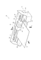
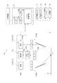
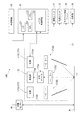
図1は、本実施形態のプリンター10の外観の構成例を示す図である。図2は、本実施形態のプリンター10の概略構成を示すブロック図である。
図1に示すように、プリンター10は、供給ユニット11、搬送ユニット12と、キャリッジ13と、キャリッジ移動ユニット14と、制御ユニット15(図2参照)と、を備えている。このプリンター10は、例えばパーソナルコンピューター等の外部機器20から入力された印刷データに基づいて、各ユニット11,12,14及びキャリッジ13を制御し、メディアM(被測定物)上に画像を印刷する。また、本実施形態のプリンター10は、予め設定された較正用印刷データに基づいてメディアM上の所定位置に測色用のカラーパッチを形成し、かつ当該カラーパッチに対する分光測定を行う。これにより、プリンター10は、カラーパッチに対する実測値と、較正用印刷データとを比較して、印刷されたカラーに色ずれがあるか否か判定し、色ずれがある場合は、実測値に基づいて色補正を行う。
以下、プリンター10の各構成について具体的に説明する。
[Schematic configuration of printer]
FIG. 1 is a diagram illustrating an example of an external configuration of a
As shown in FIG. 1, the
Hereinafter, each configuration of the
供給ユニット11は、画像形成対象となるメディアM(本実施形態では、紙面を例示)を、画像形成位置に供給するユニットである。この供給ユニット11は、例えばメディアMが巻装されたロール体111(図1参照)、ロール駆動モーター(図示略)、及びロール駆動輪列(図示略)等を備える。そして、制御ユニット15からの指令に基づいて、ロール駆動モーターが回転駆動され、ロール駆動モーターの回転力がロール駆動輪列を介してロール体111に伝達される。これにより、ロール体111が回転し、ロール体111に巻装された紙面がY方向(副走査方向)における下流側(+Y方向)に供給される。
なお、本実施形態では、ロール体111に巻装された紙面を供給する例を示すがこれに限定されない。例えば、トレイ等に積載された紙面等のメディアMをローラー等によって例えば1枚ずつ供給する等、如何なる供給方法によってメディアMが供給されてもよい。
The
In the present embodiment, an example in which the paper surface wound around the
搬送ユニット12は、供給ユニット11から供給されたメディアMを、Y方向に沿って搬送する。この搬送ユニット12は、搬送ローラー121と、搬送ローラー121とメディアMを挟んで配置され、搬送ローラー121に従動する従動ローラー(図示略)と、プラテン122と、を含んで構成されている。
搬送ローラー121は、図示略の搬送モーターからの駆動力が伝達され、制御ユニット15の制御により搬送モーターが駆動されると、その回転力により回転駆動されて、従動ローラーとの間にメディアMを挟み込んだ状態でY方向に沿って搬送する。また、搬送ローラー121のY方向の下流側(+Y側)には、キャリッジ13に対向するプラテン122が設けられている。
The
The
キャリッジ13は、メディアMに対して画像を印刷する印刷部16と、メディアM上の所定の測定位置(測定領域)の分光測定を行う分光器17(測定装置)と、を搭載している。
このキャリッジ13は、キャリッジ移動ユニット14によって、Y方向と交差する主走査方向(X方向)に沿って移動可能に設けられている。
また、キャリッジ13は、フレキシブル回路131により制御ユニット15に接続され、制御ユニット15からの指令に基づいて、キャリッジ13に搭載された印刷部16による印刷処理(メディアMに対する画像形成処理)及び、キャリッジ13に搭載された分光器17による光量測定処理を実施する。
なお、キャリッジ13の詳細な構成については後述する。
The
The
The
The detailed configuration of the
キャリッジ移動ユニット14は、本発明における移動機構を構成し、制御ユニット15からの指令に基づいて、キャリッジ13をX方向に沿って往復移動させる。
このキャリッジ移動ユニット14は、例えば、キャリッジガイド軸141と、キャリッジモーター142と、タイミングベルト143と、を含んで構成されている。
キャリッジガイド軸141は、X方向に沿って配置され、両端部がプリンター10の例えば筐体に固定されている。キャリッジモーター142は、タイミングベルト143を駆動させる。タイミングベルト143は、キャリッジガイド軸141と略平行に支持され、キャリッジ13の一部が固定されている。そして、制御ユニット15の指令に基づいてキャリッジモーター142が駆動されると、タイミングベルト143が正逆走行され、タイミングベルト143に固定されたキャリッジ13がキャリッジガイド軸141にガイドされて往復移動する。
The
The
The
次に、キャリッジ13に設けられる印刷部16、及び分光器17の構成について説明する。
[印刷部(画像形成部)の構成]
印刷部16は、本発明の画像形成部であり、メディアMと対向する部分に、インクを個別にメディアM上に吐出して、メディアM上に画像を形成する。
この印刷部16は、複数色のインクに対応したインクカートリッジ161が着脱自在に装着されており、各インクカートリッジ161からインクタンク(図示略)にチューブ(図示略)を介してインクが供給される。また、印刷部16の下面(メディアMに対向する位置)には、インク滴を吐出するノズル(図示略)が、各色に対応して設けられている。これらのノズルには、例えばピエゾ素子が配置されており、ピエゾ素子を駆動させることで、インクタンクから供給されたインク滴が吐出されてメディアMに着弾し、ドットが形成される。
Next, the configuration of the
[Configuration of printing unit (image forming unit)]
The
The
[分光器の構成]
分光器17は、測定装置に相当し、図2に示すように、光源部171と、測定部172と、を備える。
この分光器17は、光源部171からメディアM上に照明光を照射し、メディアMで反射された反射光を、測定部172で受光させる。測定部172に設けられた分光デバイス172Aは、制御ユニット15の制御に基づいて、透過波長を選択可能であり、可視光における各波長の光の光量を測定することで、メディアMの分光測定が可能となる。
なお、本実施形態では、測色規格(JIS Z 8722)により規定された光学的幾何条件の方式(45/0°測色系)に従って分光測定を実施する。すなわち、本実施形態では、光源部171からの照明光をメディアMの法線に対して45°の角度(45°±2°の角度)で入射させ、メディアMの法線方向(法線方向に対して10°以内の角度)に反射された光を測定部172で受光する。つまり、照明光がメディアMに向かう照明方向と、測定光が測定部172に向かう測定方向とが異なっている。
[Configuration of spectrometer]
The
The
In the present embodiment, the spectroscopic measurement is performed according to the optical geometric condition method (45/0 ° colorimetry system) defined by the colorimetry standard (JIS Z 8722). That is, in this embodiment, the illumination light from the
[光源部の構成]
図2に示すように、光源部171は、第一光源部171A(第一光源)と、第二光源部171B(第二光源)とを備えている。第一光源部171A、第二光源部171B、及び後述する測定部172は、Y方向に沿って配置されている。具体的には、第一光源部171Aは、測定部172の+Y側に配置され、第二光源部171Bは、測定部172の−Y側に配置されている。
第一光源部171Aは、光源171A1及び照明光学部材171A2を備え、メディアMに対して、例えば+Y側から−Y側に向かって、メディアMの法線に対して45°の角度で光を照射する。
第二光源部171Bは、光源171B1及び照明光学部材171B2を備え、メディアMに対して、例えば−Y側から+Y側に向かって、メディアMの法線に対して45°の角度で光を照射する。
[Configuration of light source section]
As shown in FIG. 2, the
The first
The second
光源171A1,171B1は、メディアMに対して照射する照明光を発光する部材である。本実施形態では、プリンター10のキャリッジ13に分光器17を搭載する構成であり、分光器17を小型、軽量化する必要がある。このため、光源171A1,171B1として、LEDやLD(半導体レーザー)等を用いることが好ましい。
照明光学部材171A2,171B2は、光源171A1,171B1から照射された照明光の照射方向や照射範囲を決定する光学部材であり、例えば、単一若しくは複数のアパーチャーやレンズ、ミラー等の光学部材により構成される。例えば、照明光学部材171A2,171B2として、単一又は複数のアパーチャーが設けられ、これらのアパーチャーを透過した所定の光路径の照明光をメディアMに照射させる構成等が例示できる。また、照明光学部材171B2として、コリメーターレンズが設けられていてもよい。この場合、光源部171からメディアMに対して平行な照明光を照射することが可能となり、メディアMの位置がZ方向に変位した場合でも、メディアM上の照明領域のサイズ(スポット径)の変動を抑制できる。
なお、第一光源部171A及び第二光源部171Bからの照明光によりメディアMが照明される領域(照明領域)やその中心(照明中心)についての説明は後述する。
また、後述の本実施形態の説明では、第一光源部171A及び第二光源部171Bの2つの光源によって2つの照明光をメディアMに照射する構成で説明を行っているが、一つの光源であっても、ハーフミラー等のビームスプリッターによって複数の照明光を得るものであってもよく、その場合は、複数の照明光の照明領域や照明中心が、後述する説明の条件を満たせば同様の効果を得ることができる。
The light sources 171A1 and 171B1 are members that emit illumination light with which the medium M is irradiated. In this embodiment, the
The illumination optical members 171A2 and 171B2 are optical members that determine the irradiation direction and irradiation range of the illumination light emitted from the light sources 171A1 and 171B1, and include, for example, optical members such as single or multiple apertures, lenses, and mirrors. Is done. For example, as the illumination optical members 171A2 and 171B2, a configuration in which a single or a plurality of apertures are provided, and illumination light having a predetermined optical path diameter that has passed through these apertures is irradiated on the medium M can be exemplified. Further, a collimator lens may be provided as the illumination optical member 171B2. In this case, it becomes possible to irradiate the illumination light parallel to the medium M from the
In addition, the area | region (illumination area | region) where the medium M is illuminated with the illumination light from the 1st
In the following description of the present embodiment, a description is given of a configuration in which two illumination lights are applied to the medium M by two light sources, the first
[測定部の構成]
測定部172は、図2に示すように、分光デバイス172Aと、受光部172Bと、受光光学部材172Cと、等により構成される。
このような測定部172では、メディアMにて反射された光を、受光光学部材172Cにより、分光デバイス172Aに導き、分光デバイス172Aにより分光された所定波長の光を受光部172Bにて受光させる。
[Configuration of measurement unit]
As shown in FIG. 2, the
In such a
受光光学部材172Cは、単一又は複数の光学部材により構成されている。この光学部材としては、例えば、単一又は複数のアパーチャーを例示できる。このようなアパーチャーを設けることで、メディアM上の所定の測定領域で反射された測定光を、分光デバイス172A及び受光部172Bに導くことができる。また、受光光学部材172Cを構成する光学部材として、例えば集光レンズ等のレンズが設けられていてもよく、バンドパスフィルターが設けられていてもよい。バンドパスフィルターを設ける場合、所望の測定波長域以外の光(例えば可視光以外の光)をカットすることができる。
The light receiving
[分光デバイスの構成]
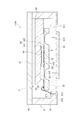
図3は、分光デバイス172Aの概略構成を示す断面図である。
分光デバイス172Aは、筐体6と、筐体6の内部に収納された波長可変干渉フィルター5(分光素子)とを備えている。
[Configuration of Spectroscopic Device]
FIG. 3 is a cross-sectional view showing a schematic configuration of the
The
(波長可変干渉フィルターの構成)
波長可変干渉フィルター5は、波長可変型のファブリーペローエタロン素子であり、本発明における分光素子を構成する。本実施形態では、波長可変干渉フィルター5が筐体6に収納された状態で分光器17に配置される例を示すが、例えば波長可変干渉フィルター5が直接分光器17に配置される構成などとしてもよい。
この波長可変干渉フィルター5は、図3に示すように、可視光に対して透光性を有する固定基板51及び可動基板52を備え、これらの固定基板51及び可動基板52が、接合膜53により接合されることで、一体的に構成されている。固定基板51には、エッチングにより形成された第一溝部511、及び第一溝部511より溝深さが浅い第二溝部512が設けられ、第一溝部511には固定電極561が、第二溝部512には固定反射膜54がそれぞれ設けられている。固定反射膜54は、例えばAg等の金属膜、Ag合金等の合金膜、高屈折層及び低屈折層を積層した誘電体多層膜、又は、金属膜(合金膜)と誘電体多層膜を積層した積層体により構成されている。
(Configuration of wavelength variable interference filter)
The variable
As shown in FIG. 3, the wavelength
可動基板52は、可動部521と、可動部521の外に設けられ、可動部521を保持する保持部522とを備えている。可動部521の固定基板51に対向する面には、固定電極561に対向する可動電極562と、固定反射膜54に対向する可動反射膜55とが設けられている。可動反射膜55としては、上述した固定反射膜54と同一の構成の反射膜が用いることができる。保持部522は、可動部521の周囲を囲うダイアフラムであり、可動部521よりも厚み寸法が小さく形成されている。
そして、上記のような波長可変干渉フィルター5では、固定電極561及び可動電極562により静電アクチュエーター56が構成され、この静電アクチュエーター56に電圧を印加することで、固定反射膜54及び可動反射膜55間のギャップGの間隔寸法を変更することが可能となる。また、可動基板52の外周部(固定基板51に対向しない領域)には、固定電極561や可動電極562と個別に接続された複数の電極パッド57が設けられている。
The
In the wavelength
(筐体の構成)
筐体6は、図3に示すように、ベース61と、ガラス基板62と、を備えている。これらのベース61及びガラス基板62は、例えば低融点ガラス接合等により接合されることで、内部に収容空間が形成されており、この収容空間内に波長可変干渉フィルター5が収納される。
(Case configuration)
As shown in FIG. 3, the
ベース61は、例えば薄板状のセラミックを積層することで構成され、波長可変干渉フィルター5を収納可能な凹部611を有する。波長可変干渉フィルター5は、ベース61の凹部611の例えば側面に固定材64により固定されている。ベース61の凹部611の底面には、光通過孔612が設けられ、この光通過孔612を覆うカバーガラス63が接合されている。
また、ベース61には、波長可変干渉フィルター5の電極パッド57に接続される内側端子部613が設けられており、この内側端子部613は、導通孔614を介して、ベース61の外側に設けられた外側端子部615に接続されている。この外側端子部615は、制御ユニット15に電気的に接続されている。
The
The
[受光部の構成]
図2に戻り、受光部172Bは、波長可変干渉フィルター5の光軸上(反射膜54,55の中心点を通る直線上)に配置され、当該波長可変干渉フィルター5を透過した光を受光領域で受光して、受光量に応じた検出信号(電流値)を出力する。なお、受光部172Bにより出力された検出信号は、I−V変換器(図示略)、増幅器(図示略)、及びAD変換器(図示略)を介して制御ユニット15に入力される。
[Configuration of light receiving unit]
Returning to FIG. 2, the
[制御ユニットの構成]
次に、制御ユニット15について説明する。
制御ユニット15は、図2に示すように、I/F151と、ユニット制御回路152と、メモリ153と、CPU(Central Processing Unit)154と、を含んで構成されている。
I/F151は、外部機器20から入力される印刷データをCPU154に入力する。
ユニット制御回路152は、供給ユニット11、搬送ユニット12、印刷部16、光源171A1,171B1、波長可変干渉フィルター5、受光部172B、及びキャリッジ移動ユニット14をそれぞれ制御する制御回路を備えており、CPU154からの指令信号に基づいて、各ユニットの動作を制御する。なお、各ユニットの制御回路が、制御ユニット15とは別体に設けられ、制御ユニット15に接続されていてもよい。
[Control unit configuration]
Next, the
As shown in FIG. 2, the
The I /
The
メモリ153は、プリンター10の動作を制御する各種プログラムや各種データが記憶されている。
各種データとしては、例えば、波長可変干渉フィルター5を制御する際の、静電アクチュエーター56への印加電圧に対する、波長可変干渉フィルター5を透過する光の波長を示したV−λデータ、印刷データとして含まれる色データに対する各インクの吐出量を記憶した印刷プロファイルデータ等が挙げられる。また、光源171A1,171B1の各波長に対する発光特性や、受光部172Bの各波長に対する受光特性(受光感度特性)等が記憶されていてもよい。
The
As various data, for example, V-λ data indicating the wavelength of light transmitted through the variable
図4は、プリンター10の制御ユニット15に含まれるCPU154の機能構成を示したブロック図である。
CPU154は、メモリ153に記憶された各種プログラムを読み出し実行することで、図4に示すように、走査制御手段154A、印刷制御手段154B、測定制御手段154C、測色手段154D、及びキャリブレーション手段154E等として機能する。
FIG. 4 is a block diagram illustrating a functional configuration of the
The
走査制御手段154Aは、供給ユニット11、搬送ユニット12、及びキャリッジ移動ユニット14を駆動させる旨の指令信号をユニット制御回路152に出力する。これにより、ユニット制御回路152は、供給ユニット11のロール駆動モーターを駆動させて、メディアMを搬送ユニット12に供給させる。また、ユニット制御回路152は、搬送ユニット12の搬送モーターを駆動させて、メディアMの所定領域をプラテン122のキャリッジ13に対向する位置まで、Y方向に沿って搬送させる。また、ユニット制御回路152は、キャリッジ移動ユニット14のキャリッジモーター142を駆動させて、キャリッジ13をX方向に沿って移動させる。
The scanning control means 154A outputs a command signal for driving the
印刷制御手段154Bは、例えば外部機器20から入力された印刷データに基づいて、印刷部16を制御する旨の指令信号をユニット制御回路152に出力する。印刷制御手段154Bからユニット制御回路152に指令信号が出力されると、ユニット制御回路152は、印刷部16に印刷制御信号を出力し、ノズルに設けられたピエゾ素子を駆動させてメディアMに対してインクを吐出させる。なお、印刷を実施する際は、キャリッジ13がX方向に沿って移動されて、その移動中に印刷部16からインクを吐出させてドットを形成するドット形成動作と、メディアMをY方向に搬送する搬送動作とを交互に繰り返し、複数のドットから構成される画像をメディアMに印刷する。
The
測定制御手段154Cは、分光測定処理を実施する。具体的には、測定制御手段154Cは、光源171A1,171B1を制御するための指令信号をユニット制御回路152に出力し、光源171A1,171B1から光を出射させる。
また、測定制御手段154Cは、波長可変干渉フィルター5を透過させる光の波長に対する静電アクチュエーター56への駆動電圧を、メモリ153のV−λデータから読み出し、ユニット制御回路152に指令信号を出力する。これにより、ユニット制御回路152は、波長可変干渉フィルター5に指令された駆動電圧を印加し、波長可変干渉フィルター5から所望の透過波長の光が透過される。
そして、測定制御手段154Cは、静電アクチュエーター56に印加した電圧(若しくは当該電圧に対応する波長可変干渉フィルター5を透過する光の波長)と関連付けてメモリ153に記憶する。
The
Further, the measurement control means 154C reads the drive voltage to the
The
測色手段154Dは、分光測定処理により得られた複数波長の光に対する受光量に基づいて、測定領域ADに対する色度を測定する。
キャリブレーション手段154Eは、測色手段154Dによる測色結果に基づいて、印刷プロファイルデータを補正(更新)する。
The
The
[照明領域と測定領域との関係]
次に、上記のような分光器17の光源部171によりメディアM上に照明光を照射した際にメディアMが照明される照明領域と、測定部172によりメディアMに対する測定を実施する際の測定領域との関係について説明する。
図5は、メディアMと分光器17との距離が変動した場合の照明領域及び測定領域の位置をYZ平面で示した図である。図6は、第一光源部171Aからの照明光のみを照射した場合に、メディアMと分光器17との距離が変動した場合の測定部172での受光量を示す図である。図7は、第二光源部171Bからの照明光のみを照射した場合に、メディアMと分光器17との距離が変動した場合の測定部172での受光量を示す図である。図8は、第一光源部171A及び第二光源部171Bからの照明光を用いた場合の、メディアMと分光器17との距離が変動した場合の測定部172での受光量を示す図である。
[Relationship between illumination area and measurement area]
Next, the illumination area where the medium M is illuminated when the illumination light is irradiated onto the medium M by the
FIG. 5 is a diagram showing the positions of the illumination area and the measurement area on the YZ plane when the distance between the medium M and the
ここで、基準位置P0とは、メディアMにうねり等がなく、キャリッジ13のZ方向への変位もない場合の、分光器17(測定部172)に対するメディアMの相対位置である。メディアMが基準位置P0に位置する場合、メディアMと分光器17との距離が所定の基準距離となる。なお、本実施形態では、基準距離をメディアMが基準位置P0に位置する際の、メディアMと分光器17との距離とするが、メディアMと測定部172との距離としてもよい。また、図6から図8において、横軸に示す測定位置とは、メディアMと分光器17との距離変動量であり、「0」はメディアMが分光器17に対して基準位置P0に位置する状態である。
Here, the reference position P 0 is a relative position of the medium M with respect to the spectroscope 17 (measurement unit 172) when the medium M has no swell and the
メディアMに対する測色処理(分光測定処理)を行う際、例えばコックリング等により、メディアMの面と、分光器17との距離が変動する場合がある。また、キャリッジ13は、キャリッジガイド軸141によりX方向に沿って移動可能となるが、キャリッジガイド軸141の一部が撓み、キャリッジ13がプラテン122側に変位する場合や、キャリッジ13の移動時の振動によりキャリッジ13がZ方向に沿って変位する場合がある。この場合もメディアMと分光器17との距離が変動する。なお、一般に、分光器17による測定に際し、メディアMと分光器17との距離の許容値(許容変動量d)は予め設定されており、基準位置P0から許容変動量dを越えて距離が変動すると、正確な測色が実施できず、エラーが出力される。ここで、メディアMと分光器17との距離が基準位置P0よりも許容変動量dだけ小さくなった場合の位置を第一位置P1とし、メディアMと分光器17との距離が基準位置P0よりも許容変動量dだけ大きくなった場合の位置を第二位置P2とする。
When performing colorimetric processing (spectral measurement processing) on the medium M, the distance between the surface of the medium M and the
また、以降の説明にあたり、第一光源部171Aの光軸とメディアMとが交わる点を第一照明中心LAとし、特に、メディアMが基準位置P0に位置する場合の第一照明中心LAをLA0、メディアMが第一位置P1に位置する場合の第一照明中心LAをLA1、メディアMが第二位置P2に位置する場合の第一照明中心LAをLA2として表記する。
さらに、第二光源部171Bの光軸とメディアMとが交わる点を第二照明中心LBとし、特に、メディアMが基準位置P0に位置する場合の第二照明中心LBをLB0、メディアMが第一位置P1に位置する場合の第二照明中心LBをLB1、メディアMが第二位置P2に位置する場合の第二照明中心LBをLB2として表記する。
本実施形態では、測定部172は、メディアMの法線方向に反射された光を受光するので、メディアMにおける測定領域ADは、メディアMの位置によらず変動しない。ここで、以降の説明にあたり、測定部172の測定領域ADの中心を測定中心Dとし、特に、メディアMが基準位置P0に位置する場合の測定中心DをD0、メディアMが第一位置P1に位置する場合の測定中心DをD1、メディアMが第二位置P2に位置する場合の測定中心DをD2として表記する。
ここで第一光源部171Aの光軸、第二光源部171Bの光軸とは、それぞれの光源による照明光がメディアを照射する際の光軸のことである。たとえば図2のように、光源17A1(又は光源171B1)とメディアMとの間にミラー等をいれて光路を変更しているような場合では、光源171A1(又は光源171B1)とミラー間の光軸のことではなく、ミラーとメディアM間の光軸がそれぞれ第一光源部171Aの光軸(第一照明光の光軸)、第二光源部171Bの光軸(第二照明光の光軸)である。
また光源部が一つであっても、ハーフミラー等のビームスプリッターによって、2つの照明光を得る場合でも同様であり、この場合、第一光源部171Aの光軸を、ビームスプリッターにより得られる1つの照明光の光軸に置き換え、第二光源部171Bの光軸を、ビームスプリッターにより得られる他の照明光の光軸に置き換えて理解すればよい。
Further, in the description below, the point where the optical axis and the media M of the first
Further, the point where the optical axis and the media M of the second
In the present embodiment, since the
Here, the optical axis of the first
Even if there is only one light source unit, the same applies when two illumination lights are obtained by a beam splitter such as a half mirror. In this case, the optical axis of the first
さらに、第一照明中心LAを中心として、光量値が所定値以上となる範囲を第一照明領域ALAとし、第二照明中心LBを中心として、光量値が所定値以上となる範囲を第二照明領域ALBとする。これらの第一照明領域ALA及び第二照明領域ALBは、光量分布がほぼ生じていない領域であり、単一光源による測定を実施した際に光量分布による測定への影響が問題とならない領域である。つまり、第一光源部171Aのみを用いた測定を実施し、第一照明中心LAを測定中心Dに一致させた際に、高精度な測定が可能な第一照明中心LAを中心とした範囲が第一照明領域ALAとなる。また、第二光源部171Bのみを用いた測定を実施し、第二照明中心LBを測定中心Dに一致させた際に、高精度な測定が可能な第二照明中心LBを中心とした範囲が第二照明領域ALBとなる。
Further, around the first center of lighting L A, a range in which the light value becomes a predetermined value or more as the first illumination area A LA, about the second center of lighting L B, a range in which the light value becomes a predetermined value or more Let it be the second illumination area A LB. The first illumination area A LA and the second illumination area A LB are areas in which the light quantity distribution is not substantially generated, and the influence on the measurement by the light quantity distribution is not a problem when the measurement with the single light source is performed. It is. That is, the measurement using only the first
測色規格(JIS Z 8722)により規定された光学的幾何条件における(45/0°測色系)の方式に従って測色を実施する場合、メディアMと分光器17との距離が変動すると、照明領域の位置が変位する。本実施形態では、第一光源部171A及び第二光源部171Bは、Y方向に沿って配置されているので、メディアMとの分光器17との距離の変動により、第一照明中心LA及び第二照明中心LBは、Y方向に沿って移動し、第一照明領域ALA及び第二照明領域ALBもY方向に沿って移動する。
具体的には、メディアMと分光器17との距離がΔdだけ小さくなると、第一照明中心LAは+Y側にΔdだけ移動し、第二照明中心LBは−Y側にΔdだけ移動する。また、メディアMと分光器17との距離がΔdだけ大きくなると、第一照明中心LAは−Y側にΔdだけ移動し、第二照明中心LBは+Y側にΔdだけ移動する。
When the color measurement is performed according to the (45/0 ° color measurement system) method in the optical geometric conditions defined by the color measurement standard (JIS Z 8722), if the distance between the medium M and the
Specifically, when the distance between the medium M and the
そして、本実施形態では、図5に示すように、第一光源部171Aは、メディアMが第一位置P1に位置する場合に、第一照明中心LA1と、測定中心D1とが一致するように、照明光を照射する。つまり、第一照明領域ALAは、メディアMが第一位置P1から第二位置P2に向かうに従って、測定領域ADよりも−Y側に移動する。したがって、図6に示すように、第一光源部171Aのみを用いた場合、メディアMが第二位置P2に位置する場合(測定位置が「+d」の場合)に、測定部172での受光量が最小となり、メディアMと分光器17との距離が小さくなるに従って、測定部172での受光量が増大し、第一位置P1となった際(測定位置が「−d」の場合)に、測定部172での受光量が最大となる。
In the present embodiment, as shown in FIG. 5, the first
一方、第二光源部171Bは、図5に示すように、メディアMが第二位置P2に位置する場合に、第二照明中心LB2と、測定中心D2とが一致するように、照明光を照射する。つまり、第二照明領域ALBは、メディアMが第二位置P2から第一位置P1に向かうに従って、測定領域ADよりも+Y側に移動する。したがって、図7に示すように、第二光源部171Bのみを用いた場合、メディアMが第一位置P1に位置する場合に、測定部172での受光量が最小となり、メディアMと分光器17との距離が大きくなるに従って、測定部172での受光量が増大し、第二位置P2となった際に、測定部172での受光量が最大となる。
On the other hand, as shown in FIG. 5, the second
また、測定領域ADは、測定中心Dからの距離が許容変動量dより大きい寸法となる領域であり、かつメディアMが基準位置P0に位置する際に、第一照明領域ALA及び第二照明領域ALBに含まれる。
そして、メディアMが基準位置P0に位置する場合に、第一照明中心LA0及び第二照明中心LB0は、測定中心D0よりも距離dだけ−Y側に位置し、第一光源部171Aからの照明光の光軸と、第二光源部171Bの照明光の光軸とが当該位置で交差する。
つまり、メディアMが基準位置P0に位置する際の位置をZ=0とすると、第一光源部171Aの光軸及び第二光源部171Bの光軸は、YZ平面における座標(y,z)=(−d,0)を交点として交わり、かつ、当該交点は、メディアMをZ方向から見た際に、測定領域AD内に含まれる。
このような構成では、メディアMと分光器17との距離が変動した場合でも、第一照明中心LA及び第二照明中心LBのいずれかが、測定領域AD内に含まれることになり、かつ、第一照明中心LA及び第二照明中心LBのいずれか一方が測定中心Dから離隔しても他方が近接する。よって、測定領域AD内の光量が著しく低下することなく、図8に示すように、メディアMと分光器17との距離によらず、測定領域ADに対して略均一な光量の照明光を照射させることが可能となり、測定精度の低下を抑制することが可能となる。
The measurement area AD is an area whose distance from the measurement center D is larger than the allowable variation d, and when the medium M is located at the reference position P 0 , the first illumination area A LA and the first illumination area A LA are measured. It is included in the second illumination area A LB.
When the medium M is located at the reference position P 0 , the first illumination center L A0 and the second illumination center L B0 are located on the −Y side by the distance d from the measurement center D 0 , and the first light source unit The optical axis of the illumination light from 171A and the optical axis of the illumination light of the second
That is, when the position at which the media M is positioned at the reference position P 0 and Z = 0, the optical axis of the optical axis and the second
In such a configuration, even when the distance between the
[分光測定方法]
次に、本実施形態のプリンター10における分光測定方法について、図面に基づいて説明する。
図9は、プリンター10における分光測定方法を示すフローチャートである。図10は、本実施形態において形成されるカラーチャートの一例を示す図である。
(カラーチャートの形成)
プリンター10による分光測定方法では、まず、メディアM上にカラーパッチ31を含むカラーチャートを形成する。
これには、走査制御手段154Aは、メディアMを所定位置にセットする(ステップS1)。すなわち、走査制御手段154Aは、供給ユニット11、搬送ユニット12を制御して、メディアMを副走査方向(+Y方向)に搬送し、メディアMの所定の印刷開始位置をプラテン122上にセットする。また、走査制御手段154Aは、キャリッジ13を、初期位置(例えば主走査方向の−X側端部)に移動させる。
[Spectroscopic measurement method]
Next, a spectroscopic measurement method in the
FIG. 9 is a flowchart illustrating a spectroscopic measurement method in the
(Formation of color chart)
In the spectroscopic measurement method using the
For this, the scanning control means 154A sets the medium M at a predetermined position (step S1). That is, the
この後、印刷制御手段154Bは、メモリ153から較正用印刷データを読み出し、走査制御手段154Aによる制御と同期して、カラーチャートをメディアM上に印刷する(ステップS2)。
すなわち、走査制御手段154Aにより、キャリッジ13を+X側に例えば一定速度で走査させる。印刷制御手段154Bは、例えば走査開始からの時間に応じてキャリッジ13の印刷部16の位置を特定し、較正用印刷データに基づいた所定位置に所定色のノズルからインクを吐出させてドットを形成する(ドット形成動作)。また、走査制御手段154Aは、キャリッジ13が+X側端部まで移動されると、供給ユニット11及び搬送ユニット12を制御してメディアMを+Y方向に搬送する(搬送動作)。そして、走査制御手段154Aは、キャリッジ13を−X方向に走査させ、印刷制御手段154Bは、較正用印刷データに基づいて、所定位置にドットを形成する。
以上のようなドット形成動作と搬送動作を繰り返すことで、メディアM上に図10に示すようなカラーチャート3が形成される。具体的には、複数色のカラーパッチ31がX方向に沿って隙間なく配置されて構成されたカラーパッチ群30を、Y方向に沿って複数個配置させたカラーチャート3が形成される。
Thereafter, the
That is, the
A
ステップS2の後、印刷されたカラーチャート3のインクが乾燥されると、制御ユニット15は、白色基準に対する分光測定処理を実施する(ステップS3)。この白色基準としては、メディアMにおいて画像が印刷されていない領域であってもよく、プラテン122に設けられた白色基準物(図示略)であってもよい。
この分光測定処理では、測定制御手段154Cは、メモリ153に記憶されたV−λデータに基づいて、波長可変干渉フィルター5の静電アクチュエーター56に駆動電圧を順次切り替え、例えば400nmから700nmの可視光域における20nm間隔となる16バンドの測定波長に対する測定値(光量)を測定する。
After step S2, when the ink of the printed
In this spectroscopic measurement process, the
次に、走査制御手段154Aは、搬送ユニット12及びキャリッジ移動ユニット14を制御して、カラーパッチ31上に測定領域ADが位置するように、キャリッジ13を移動させる(ステップS4)。
そして、測定制御手段154Cは、上記ステップS5と同様の処理を実施して、カラーパッチに対する分光測定処理を実施し、各波長に対する測定値を取得する(ステップS5)。
Next, the
Then, the
この際、本実施形態では、メディアMと分光器17との距離が変動した場合でも、その変動量が許容変動量d以内であれば、上述したように、測定領域ADに対して十分な光量の照明光を照射させることができ、高精度な測定を行うことができる。
また、本実施形態では、第一光源部171A及び第二光源部171Bが測定部172を挟んでY方向に沿って配置されている。このような構成では、メディアMと分光器17との距離が変動した場合、第一照明領域ALAや第二照明領域ALBがY方向に移動する。したがって、測定対象となるカラーパッチ31に対してX方向に隣り合う他のカラーパッチ31上への第一照明領域ALAや第二照明領域ALBの移動を抑制できる。つまり、他のカラーパッチ31にて反射された光が測定部172に入射されず、測定精度の低下が抑制される。
At this time, in the present embodiment, even when the distance between the medium M and the
In the present embodiment, the first
この後、測定制御手段154Cは、未測定のカラーパッチがあるか否か判定する(ステップS6)。
ステップS6において「Yes」と判定された場合、ステップS4に戻り、走査制御手段154Aは、搬送ユニット12やキャリッジ移動ユニット14を制御して、測定部172の測定領域ADを次のカラーパッチ31に移動させ、当該カラーパッチ31に対する分光測定処理を実施する。
Thereafter, the
If “Yes” is determined in
ステップS6において「No」と判定された場合は、制御ユニット15は、測色処理を実施する(ステップS7)。具体的には、測色手段154Dは、各測定波長に対する測定値及び基準測定値に基づいて、各測定波長に対する反射率を算出し、算出された反射率に基づいて、測色値(例えばXYZ値、L*a*b*値等)を算出し、メモリ153に記憶する。また、キャリブレーション手段154Eは、各カラーパッチの測色結果に基づいて、メモリ153に記憶された印刷プロファイルデータを更新する。
When it is determined as “No” in step S6, the
[本実施形態の作用効果]
本実施形態のプリンター10は、キャリッジ13に搭載された分光器17を有し、当該分光器17は、メディアMに照明光を照射する第一光源部171A及び第二光源部171Bを含む光源部171と、被測定物で反射された反射光(測定光)を測定する測定部172と、を含む。そして、メディアMが基準位置P0に位置する場合に、第一照明中心LA0及び第二照明中心LB0と、測定中心D0とがずれており、異なる位置に存在する。
このような構成では、メディアMにコックリング等が生じ、メディアMと分光器17との相対距離が変動した場合に、第一照明中心LA0及び第二照明中心LB0の少なくともいずれかが測定中心Dに近づき、測定領域ADに照射される照明光の光量減退を抑制できる。また、基準位置P0においては、第一照明中心LA0及び第二照明中心LB0と測定中心D0とがずれているものの、第一照明領域ALA及び第二照明領域ALBの双方により測定領域AD内に照明光が照射されるので、十分な光量が測定領域ADに照射され、十分な測定精度を得ることができる。以上により、本実施形態では、コックリング等によりメディアMがZ方向に変位した場合や、振動等によりキャリッジ13がZ方向に変位して、メディアMと分光器17との距離が変動した場合でも、測定領域ADに照射される光量の減少を抑制でき、高精度な分光測定を実施することができる。
[Operational effects of this embodiment]
The
In such a configuration, when cockling or the like occurs in the medium M and the relative distance between the medium M and the
本実施形態では、第一光源部171Aの光軸と、第二光源部171Bの光軸とが、座標(y,z)=(−d,0)を交点として交わり、かつ当該交点が、メディアMの法線方向から見た際に測定領域AD内に含まれている。
このような構成では、測定領域ADに対して互いに異なる方向から照明光を照射する構成となる。これにより、メディアMと分光器17との距離が変動した場合でも、第一照明中心LA及び第二照明中心LBのいずれかが、測定領域AD内に含まれることになり、かつ、第一照明中心LA及び第二照明中心LBのいずれか一方が測定中心Dから離隔しても他方が近接する。よって、測定領域AD内の光量が著しく低下することなく、測定領域ADに対して略均一な光量の照明光を照射させることができ、高精度な測定を実現できる。
In the present embodiment, the optical axis of the first
In such a configuration, the measurement region AD is irradiated with illumination light from different directions. Accordingly, even when the distance between the
本実施形態では、メディアMが基準位置P0に位置する場合に、第一照明中心LA0及び第二照明中心LB0が測定中心D0の−Y側にずれて位置している。このような構成により、メディアMと分光器17との距離が小さくなる場合に、第一照明中心LAが測定中心Dに近づき、メディアMと分光器17との距離が大きくなる場合に、第二照明中心LBが測定中心Dに近づく。このため、メディアMと分光器17との距離が近くなる場合でも遠くなる場合でも、測定領域ADに照射される照明光の総光量の変動が抑制されることになる。よって、測定精度の低下を抑制した、高精度な測定を実施できる。
In the present embodiment, when the medium M is located at the reference position P 0 , the first illumination center L A0 and the second illumination center L B0 are displaced from the −Y side of the measurement center D 0 . With this configuration, when the distance between the medium M and the
本実施形態では、メディアMが基準位置P0から許容変動量dだけ小さくなる第一位置P1において、第一照明中心LA1と測定中心D1とが一致する。この場合、メディアMが分光器17側に許容変動量dだけ変位した場合に、第二照明領域ALBが測定領域ADから最も離れた位置(−Y側)にずれるので、第二光源部171Bによる照明光の光量が最小となる。しかしながら、測定中心D1に第一照明中心LA1が一致することで、第一光源部171Aによる照明光の光量が最大となり、当該第一光源部171Aの照明光により、高精度な測定を実施することができる。
In the present embodiment, the first illumination center L A1 and the measurement center D 1 coincide with each other at the first position P 1 where the medium M becomes smaller than the reference position P 0 by the allowable variation d. In this case, when the medium M is displaced to the
本実施形態では、メディアMが基準位置P0から許容変動量dだけ大きくなる第二位置P2において、第二照明中心LB2と測定中心D2とが一致する。この場合、メディアMが分光器17とは反対側に許容変動量dだけ変位した場合に、第一照明領域ALAが測定領域ADから最も離れた位置(−Y側)にずれるので、第一光源部171Aによる照明光の光量が最小となる。しかしながら、測定中心D2に第二照明中心LB2が一致することで、第二光源部171Bによる照明光の光量が最大となり、当該第二光源部171Bの照明光により、高精度な測定を実施することができる。
In the present embodiment, the second illumination center L B2 and the measurement center D 2 coincide with each other at the second position P 2 where the medium M increases from the reference position P 0 by the allowable variation amount d. In this case, when the medium M is displaced to the side opposite to the
本実施形態では、分光器17がキャリッジ13に搭載され、キャリッジ移動ユニット14によって、X方向に沿って移動可能に構成されている。そして、第一光源部171A及び第二光源部171Bは、X方向に交差(本実施形態では、直交を例示)するY方向に沿って配置されている。
本実施形態のように、プリンター10に分光器17を搭載する場合では、プリンター10の印刷部16によりX方向に沿って配列される複数のカラーパッチを分光器17により測定し、測定結果(測色結果)に基づいて印刷プロファイルを補正(更新)する。このようなカラーパッチに対する測定では、1つ1つのカラーパッチに対して高精度な測定を行う必要がある。
ここで、X方向に沿って第一光源部171A及び第二光源部171Bを配置すると、メディアMと分光器17との距離が変動した場合に、第一照明領域ALAや第二照明領域ALBが、X方向に沿ってずれる。この場合、測定対象となるカラーパッチに隣接する他のカラーパッチに第一照明領域ALAや第二照明領域ALBが移動し、当該カラーパッチにて反射された光が測定部172に入射される可能性があり、この場合、測定対象に対する正確な測色結果が得られない。これに対して、本実施形態では、上記構成とすることで、メディアMと分光器17との距離が変動した場合に、第一照明領域ALAや第二照明領域ALBが、Y方向に沿って位置がずれる。このため、測定対象のカラーパッチに対して、X方向に隣り合う他のカラーパッチからの反射光が測定部172に入射される不都合を抑制でき、測定対象のカラーパッチに対する高精度な測定を実施することができる。
In this embodiment, the
When the
Here, when the first
また、隣り合うカラーパッチからの反射光が測定部172に入射されないように、カラーパッチのX方向の幅寸法を大きくすることも考えられる。しかしながら、この場合では、X方向に沿って配置可能なカラーパッチの数が少なくなる。通常、X方向に沿って複数のカラーパッチを配置したカラーパッチ群を、Y方向に沿って複数配置するが、カラーパッチ群に含まれるカラーパッチの数が少ないと、より多くのカラーパッチ群をY方向に沿って配置する必要が生じ、その分、測定に係る時間が長くなる。これに対して、本実施形態では、上記構成によって、各カラーパッチのX方向に沿った幅寸法を大きくする必要がなく、X方向に沿って多くのカラーパッチを配置したカラーパッチ群を形成でき、測定に要する時間も短縮できる。
It is also conceivable to increase the width dimension of the color patch in the X direction so that reflected light from adjacent color patches does not enter the
本実施形態では、測定部172は、分光デバイス172Aを備え、分光デバイス172Aで分光された光を受光部172Bで受光する。このため、メディアMの測定領域ADに対する分光測定を実施することができる。また、メディアMに形成された画像の色度等を精度よく算出することも可能となるので、このような分光測定結果や算出された色度に基づいて、印刷部16のキャリブレーションを高精度に実施することができる。
In the present embodiment, the
また、分光デバイス172Aとして、波長可変干渉フィルター5を用いる。このような波長可変干渉フィルター5は、一対の反射膜54,55を対向させた簡素な構成となり、例えばAOTFやLCTF等の他の分光素子を用いる場合に比べて、安価で小型化が可能となり、測定部172を小型化できる。よって、キャリッジ13に対して測定部172を搭載しやすく、測定部172の重量によってキャリッジ13の移動が阻害される等の不都合も抑制できる。
また、キャリッジ13に、印刷部16と分光器17とを搭載できるので、印刷部16用のキャリッジと、分光器17用のキャリッジとを用いる場合に比べて構成の簡略化を図れる。また、キャリッジ13に印刷部16と分光器17との双方を搭載することで、印刷部16によるメディアMへの画像形成(印刷)を行った後、形成された画像に対する測色を、分光器17を用いて即座に実施することができる。印刷部16による印刷直後では、乾燥していないインクによってメディアMにコックリングが生じる場合があるが、本実施形態では、上述のようにこのようなコックリングによる測定精度の低下を抑制できる。
Further, the wavelength
In addition, since the
本実施形態では、メディアMに対して画像を形成する印刷部16を備えたプリンター10に、分光器17を搭載し、メディアMに対する分光測定を実施する。そして、キャリブレーション手段154Eは、分光測定結果から算出された各測定波長の反射率や色度に基づいて、印刷プロファイルデータを更新する。
このようなプリンター10では、上述のように、カラーパッチに対して高精度な分光測定を実施でき、精度の高い測色処理を行うことができる。したがって、当該測色処理の測色結果に基づいて印刷プロファイルデータを更新することで、印刷部16によりユーザーが所望する色度を高精度に再現した画像を形成することができる。
In the present embodiment, the
In such a
[第二実施形態]
次に、本発明に係る第二実施形態について説明する。
上述した第一実施形態では、第一光源部171A及び第二光源部171Bからの照明光をメディアMに対して45°の角度で入射させ、メディアMの法線方向に反射された測定光を測定部172で受光する例を示した。
これに対して、第二実施形態では、光源からの照明光をメディアMの法線方向から照射し、45°にて反射された光を測定部にて測定する例を説明する。
[Second Embodiment]
Next, a second embodiment according to the present invention will be described.
In the first embodiment described above, illumination light from the first
On the other hand, 2nd embodiment demonstrates the example which irradiates the illumination light from a light source from the normal line direction of the medium M, and measures the light reflected at 45 degrees in a measurement part.
図11は、第二実施形態のプリンター10Aの概略構成を示すブロック図である。なお、既に説明した構成については同符号を付し、その説明を省略又は簡略化する。
第二実施形態のプリンター10Aは、第一実施形態と同様、供給ユニット11、搬送ユニット12、キャリッジ13、キャリッジ移動ユニット14、制御ユニット15を含む。また、キャリッジ13は、印刷部16と、分光器17Aとを含む。
FIG. 11 is a block diagram illustrating a schematic configuration of a
The
本実施形態の分光器17Aは、図11に示すように、光源部171C及び測定部173を含んで構成されている。
本実施形態の光源部171Cは、1つの光源171C1と、当該光源171C1からの照明光の光路上に設けられる照明光学部材171C2とを備える。光源171C1は、第一実施形態の光源171A1や光源171B1と同様の構成である。照明光学部材171C2は、第一実施形態の照明光学部材171A2や照明光学部材171B2と同様、光源171C1からの照明光をメディアM上に導く光学部材であり、例えばアパーチャー等により構成される。
As shown in FIG. 11, the
The
測定部173は、図11に示すように、第一測定部173Aと、第二測定部173Bとを備えている。具体的には、第一測定部173Aは、光源部171Cの+Y側に配置され、第二測定部173Bは、光源部171Cの−Y側に配置されている。
第一測定部173Aは、分光デバイス173A1と、受光部173A2と、受光光学部材173A3と、等により構成される。また、第二測定部173Bは、分光デバイス173B1と、受光部173B2と、受光光学部材173B3と、等により構成される。
分光デバイス173A1,173B1は、第一実施形態における分光デバイス172Aと同様の構成を有し、波長可変干渉フィルター5を備えて構成されている。
受光部173A2,173B2は、第一実施形態における受光部172Bと同様であり、受光部173A2は分光デバイス173A1により分光された所定波長の光を受光し、受光部173B2は分光デバイス173B1により分光された所定波長の光を受光する。
受光光学部材173A3,173B3は、第一実施形態の受光光学部材172Cと略同様であり、例えばアパーチャーやミラー、反射鏡等により構成されている。そして、受光光学部材173A3は、メディアM上で45°の角度で+Y側に反射された測定光を、分光デバイス173A1及び受光部173A2に導く。また、受光光学部材173B3は、メディアM上で45°の角度で−Y側に反射された測定光を、分光デバイス173B1及び受光部173B2に導く。
As shown in FIG. 11, the
The
The spectroscopic devices 173A1 and 173B1 have the same configuration as the
The light receiving units 173A2 and 173B2 are the same as the
The light receiving optical members 173A3 and 173B3 are substantially the same as the light receiving
[照明領域と測定領域との関係]
図12は、メディアMと分光器17Aとの距離が変動した場合の照明領域及び測定領域の位置をYZ平面で示した図である。
本実施形態では、測色規格(JIS Z 8722)により規定された光学的幾何条件における(0/45°測色系)の方式に従って測色を実施し、メディアMに対して法線方向から光を照射し、45°で反射された測定光を測定する。
したがって、本実施形態では、光源部171Cからの照明光は、メディアMと分光器17Aとの距離によらず略定位置に照射される。光源部171Cの光軸とメディアMとが交わる点を照明中心LCとし、特に、メディアMが基準位置P0に位置する場合の照明中心LCをLC0、メディアMが第一位置P1に位置する場合の照明中心LCをLC1、メディアMが第二位置P2に位置する場合の照明中心LCをLC2として表記する。
一方、第一測定部173A及び第二測定部173Bの測定領域は、メディアMと分光器17Aとの距離に応じてY方向に沿って変動する。ここで、第一測定部173Aによる測定領域ADAの中心を第一測定中心DAとし、第二測定部173Bによる測定領域ADBの中心を第二測定中心DBとする。特に、メディアMが基準位置P0に位置する場合の第一測定中心DAをDA0、第二測定中心DBをDB0とし、メディアMが第一位置P1に位置する場合の第一測定中心DAをDA1、第二測定中心DBをDB1とし、メディアMが第二位置P2に位置する場合の第一測定中心DAをDA2、第二測定中心DBをDB2として表記する。
[Relationship between illumination area and measurement area]
FIG. 12 is a diagram showing the positions of the illumination area and the measurement area on the YZ plane when the distance between the medium M and the
In the present embodiment, color measurement is performed according to the (0/45 ° color measurement system) method in the optical geometric conditions defined by the color measurement standard (JIS Z 8722), and light is emitted from the normal direction to the medium M. The measurement light reflected at 45 ° is measured.
Therefore, in the present embodiment, the illumination light from the
On the other hand, the measurement areas of the
0/45°測色系では、メディアMと分光器17Aとの距離がΔdだけ小さくなると、第一測定中心DAは+Y側にΔdだけ移動し、第二測定中心DBは−Y側にΔdだけ移動する。また、メディアMと分光器17との距離がΔdだけ大きくなると、第一測定中心DAは−Y側にΔdだけ移動し、第二測定中心DBは+Y側にΔdだけ移動する。
0 In / 45 ° colorimetric system, the distance between the medium M and the
そして、本実施形態では、図12に示すように、第一測定部173Aは、メディアMが第一位置P1に位置する場合に、第一測定中心DA1と、照明中心LC1とが一致するように配置位置が設定され、または、受光光学部材173A3が構成されている。つまり、第一測定部173Aは、メディアMが第一位置P1に位置する場合に、照明中心LC1を第一測定中心DA1とした測定領域ADAからの測定光を測定する。
一方、第二測定部173Bは、メディアMが第二位置P2に位置する場合に、第二測定中心DB2と、照明中心LC2とが一致するように配置位置が設定され、または、受光光学部材173B3が構成されている。つまり、第二測定部173Bは、メディアMが第二位置P2に位置する場合に、照明中心LC2を第二測定中心DB2とした測定領域ADBからの測定光を測定する。
In the present embodiment, as shown in FIG. 12, the
On the other hand, the
また、照明領域ALCは、照明中心LCからの距離が許容変動量dより大きい寸法の領域であり、かつメディアMが基準位置P0に位置する際に、照明領域ALC内に第一測定領域ADA及び第二測定領域ADBが含まれる。
そして、メディアMが基準位置P0に位置する場合に、第一測定中心DA0及び第二測定中心DB0は、照明中心LC0よりも距離dだけ−Y側に位置し、第一測定部173Aの光軸と、第二測定部173Bの光軸とが当該位置で交差する。
つまり、第一測定部173Aの光軸及び第二測定部173Bの光軸は、YZ平面における座標(y,z)=(−d,0)を交点として交わり、かつ、当該交点は、メディアMをZ方向から見た際に、照明領域ALC内に含まれる。
このような構成では、メディアMと分光器17Aとの距離が変動した場合でも、第一測定領域ADA及び第二測定領域ADBのいずれかが、照明領域ALC内に含まれることになり、かつ、第一測定中心DA及び第二測定中心DBのいずれか一方が照明中心LCから離隔しても他方が近接する。よって、これらの第一測定部173A及び第二測定部173Bのうち、受光量が大きい一方を選択する、又は第一測定部173A及び第二測定部173Bの測定結果の平均値を用いることで、メディアMと分光器17Aとの距離によらず、十分な光量の照明光を照射された領域に対する測定を実施することができ、高精度な測定を実施できる。
Further, the illumination area A LC, the illumination center L the distance from C is an area of the allowable variation amount d is larger than the size, and when the medium M is positioned at the reference position P 0, the first in the illumination area A LC A measurement area A DA and a second measurement area A DB are included.
When the medium M is located at the reference position P 0 , the first measurement center D A0 and the second measurement center D B0 are located on the −Y side by the distance d from the illumination center L C0 , and the first measurement unit The optical axis of 173A and the optical axis of the
That is, the optical axis of the
In such a configuration, even when the distance between the medium M and the
[第三実施形態]
次に、本発明に係る第三実施形態について説明する。
上記第一実施形態では、測定部172により測定された測定結果に基づいて、測色処理を実施する例を示した。これに対して、本実施形態では、さらに、測定部により測定された測定結果をメディアと分光器との距離に応じて補正し、その補正結果に基づいて測色処理を実施する点で上記第一実施形態と相違する。
[Third embodiment]
Next, a third embodiment according to the present invention will be described.
In the first embodiment, the example in which the color measurement process is performed based on the measurement result measured by the
図13は、第三実施形態におけるプリンターの概略構成を示すブロック図である。
本実施形態では、プリンター10Bは、第一実施形態と同様、供給ユニット11、搬送ユニット12、キャリッジ13、キャリッジ移動ユニット14、制御ユニット15を含む。そして、本実施形態では、図13に示すように、キャリッジ13には、印刷部16及び分光器17に加え、更に、距離センサー18が設けられている。なお、距離センサー18は、分光器17に組み込まれる構成としてもよい。
FIG. 13 is a block diagram illustrating a schematic configuration of a printer according to the third embodiment.
In the present embodiment, the
距離センサー18は、本発明の距離計測部であり、印刷部16及び分光器17と共にキャリッジ13に設けられる。距離センサー18は、例えば光源から光をPSD(Position Sensing Device)にて受光させることで、三角法を用いて距離を算出するセンサー等を用いることができる。また、距離センサー18としては、その他の測長方式の距離センサーを用いてもよく、例えばレーザ光を、参照光及び測定光に分離し、メディアMにて反射された測定光と参照光とを合成した合成光の干渉縞に基づいて距離を算出する距離センサー等を用いてもよい。
また、光学式の距離センサー18を用いる場合、分光器17の光源部171の照明光を用いることが好ましい。この場合、例えばメディアMにコックリング等によるうねりが生じていても、分光器17による分光測定が実施される測定領域ADにおける、メディアM及び分光器17の距離が計測される。
The
Moreover, when using the
そして、本実施形態の制御ユニット15において、メモリ153には、距離−光量データが記憶されている。この距離−光量データは、メディアM及び分光器17の距離に対する測定領域ADにおける光量変動量の関係を示すデータである。
また、測色手段154Dは、上記第一実施形態と同様、分光測定処理により得られた複数波長の光に対する受光量に基づいて、測定領域ADに対する色度を測定する。これに加え、本実施形態の測色手段154Dは、本発明の補正部として機能し、距離センサー18により計測された距離に基づいて、測色結果を補正し、補正した測色結果に基づいて色度を測定する。
In the
Similarly to the first embodiment, the
[分光測定方法]
次に、本実施形態のプリンター10Bにおける分光測定方法について、図面に基づいて説明する。
図14は、プリンター10Bにおける分光測定方法を示すフローチャートである。
本実施形態では、図9に示すような第一実施形態の分光測定方法と略同様の方法により、カラーパッチに対する分光測定を実施する。
すなわち、図14に示すように、ステップS1からステップS2の処理により、カラーパッチ31を有するカラーチャート3を形成し、ステップS3の処理により、白色基準に対する分光測定を実施する。この後、本実施形態では、白色基準の測定を実施した位置において、距離センサー18により、白色基準と分光器17との距離を計測する(ステップS11)。測定制御手段154Cは、ステップS3で測定された受光量(基準光量)と、ステップS11で取得した距離と、を測定波長(又は静電アクチュエーター56への印加電圧)と関連付けてメモリ153に記憶する。
[Spectroscopic measurement method]
Next, a spectroscopic measurement method in the
FIG. 14 is a flowchart illustrating a spectroscopic measurement method in the
In this embodiment, spectroscopic measurement is performed on a color patch by a method substantially similar to the spectroscopic measurement method of the first embodiment as shown in FIG.
That is, as shown in FIG. 14, the
また、測定制御手段154Cは、ステップS4及びステップS5により、カラーパッチ31に対する分光測定を実施した後、ステップS5における受光量の取得タイミングと同期して、距離センサー18により計測されたメディアM及び分光器17の距離を取得する(ステップS12)。測定制御手段154Cは、ステップS5で測定された受光量(測定光量)と、ステップS12で取得した距離と、を測定波長(又は静電アクチュエーター56への印加電圧)と関連付けてメモリ153に記憶する。
In addition, the
以上のステップS4からステップS12の処理をステップS6において「No」と判定されるまで繰り返し、ステップS6において「No」と判定されると、測色手段154Dは、メモリ153に記憶された距離−光量データに基づいて、ステップS3において測定された基準光量、及びステップS5において測定された測定光量を補正する(ステップS13)。
The processing from step S4 to step S12 is repeated until it is determined as “No” in step S6. When it is determined as “No” in step S6, the
以下、測色手段154Dによる光量補正について、説明する。
本実施形態では、第一実施形態と同様、メディアMが基準位置P0に位置する際に、第一照明中心LA0及び第二照明中心LB0が、測定中心D0と異なる位置に位置し、メディアMと分光器17との距離が変動した場合に、第一照明中心LA及び第二照明中心LBのいずれかが測定中心Dに近接する構成となる。このため、測定部172の受光部172Bに入射される受光光量(受光される総光量)の変動を抑制でき、精度の高い測定結果を得ることが可能となる。しかしながら、図8に示すように、メディアMと分光器17との距離によって、僅かながら受光部172Bにて受光される受光光量が変化する。
これに対して、本実施形態では、上記のような、メディアM及び分光器17の距離に対する、受光部172Bでの受光量の変化を示した距離−光量データがメモリ153に記憶され、この距離−光量データに基づいた補正が実施される。
Hereinafter, the light amount correction by the
In the present embodiment, as in the first embodiment, when the medium M is located at the reference position P 0 , the first illumination center L A0 and the second illumination center L B0 are located at positions different from the measurement center D 0. , when the distance between the medium M and the
On the other hand, in the present embodiment, the distance-light quantity data indicating the change in the amount of light received by the
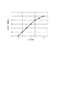
図15は、本実施形態における距離−光量データの一例を示す図である。
具体的には、図15に示すように、距離−光量データには、メディアM及び分光器17の距離の変化量Δd(メディアMの基準位置P0からのZ方向変位量)に対する、受光部172Bでの受光量変化率(以降、補正係数と称する場合もある)が記録されている。また、これらの距離−光量データは、測定波長毎にそれぞれ設けられている。例えば、本実施形態では、可視光域(400nm〜700nm)における16バンドの測定波長に対して分光測定が実施されるので、これらの16バンドの測定波長のそれぞれに対する距離−光量データがメモリ153に記憶されている。
なお、図15では、距離変化量に対する補正係数を記録した距離−光量データを例示するが、メディアM及び分光器17の距離に対する補正係数が記録されていてもよい。
FIG. 15 is a diagram illustrating an example of distance-light quantity data in the present embodiment.
Specifically, as shown in FIG. 15, in the distance-light quantity data, the
15 illustrates distance-light quantity data in which a correction coefficient for the distance change amount is recorded, but a correction coefficient for the distance between the medium M and the
そして、ステップS13では、測色手段154Dは、距離−光量データから、ステップS11で取得した距離に応じた補正係数(光量変化率)を取得し、ステップS3にて測定された基準光量を補正係数で除算した補正基準光量を算出する。同様に、距離−光量データからステップS12で取得した距離に応じた補正係数を取得し、ステップS5にて測定された測定光量を補正係数で除算した補正測定光量を算出する。
この後、測色手段154Dは、第一実施形態と同様、ステップS7の測色処理を実施する。
In step S13, the
Thereafter, the
[本実施形態の作用効果]
本実施形態のプリンター10Bでは、キャリッジ13に、分光器17及び距離センサー18が搭載されている。そして、測色手段154Dは、距離センサー18により計測されたメディアM及び分光器17の距離を用いて、分光器17を用いた分光測定により得られた各波長に対する受光量を補正する。これにより、メディアMと分光器17との距離が変動した場合でも、その距離に応じて受光量を補正することができるので、当該受光量に基づいて、測定対象であるカラーパッチに対する高精度な測色処理を実施することができる。
[Operational effects of this embodiment]
In the
[その他の実施形態]
なお、本発明は上述の各実施形態に限定されるものではなく、本発明の目的を達成できる範囲での変形、改良、及び各実施形態を適宜組み合わせる等によって得られる構成は本発明に含まれるものである。
[Other Embodiments]
Note that the present invention is not limited to the above-described embodiments, and the present invention includes configurations obtained by modifying, improving, and appropriately combining the embodiments as long as the object of the present invention can be achieved. Is.
例えば、上記各実施形態では、メディアMが不透明部材若しくは半透明部材であり、メディアMにより反射された光を分光器17に入射させる構成を例示したが、これに限定されない。透明部材のメディアMを測定する場合や、半透明部材を透過した透過光を測定する場合では、光源部171又は測定部172をプラテン122側に設ける構成としてもよい。ただし、この場合、キャリッジ13の移動とともに、プラテン122側に設けられた光源部171又は測定部172をキャリッジ13の移動方向に移動させるための移動機構が必要となる。
For example, in each of the above-described embodiments, the medium M is an opaque member or a translucent member, and the configuration in which the light reflected by the medium M is incident on the
上記第一実施形態において、光源部171に含まれる複数の光源として、第一光源部171A及び第二光源部171Bの2つの光源を有する例を示したが、これに限定されない。例えば、3つ以上の光源が設けられていてもよい。
例えば3つの光源(第一光源部、第二光源部、及び第三光源部)を設ける場合では、メディアMの法線方向から見た際に、第一光源部、第二光源部、及び第三光源部が回転対象となるように、測定中心を中心に120°間隔となるように配置する。そして、メディアMが第一位置P1に位置する際に、第一光源部による第一照明中心がメディア上の測定中心に一致し、メディアMが第二位置P2に位置する際に、第二光源部による第二照明中心がメディア上の測定中心に一致し、メディアMが基準位置P0に位置する際に、第三光源部による第三照明中心がメディア上の測定中心に一致するように、各々照明光軸が構成されている。このような構成では、上記第一実施形態と同様、メディアMが基準位置P0から第一位置P1側に移動した場合には、第一光源部の照明光の光量により測定領域内の光量減少を抑制でき、メディアMが基準位置P0から第二位置P2側に移動した場合には、第二光源部の照明光の光量により測定領域内の光量減少を抑制できる。さらに、上記第一実施形態では、メディアMが基準位置P0に位置する際に、第一照明中心及び第二照明中心が測定中心からずれていたが、本変形例では、第三光源部による第三照明中心が測定中心に一致するので、メディアMが基準位置P0に位置する際の光量分布をより均一にでき、更なる測定精度の向上を図れる。
In the first embodiment, the example in which the two light sources of the first
For example, when three light sources (first light source unit, second light source unit, and third light source unit) are provided, when viewed from the normal direction of the medium M, the first light source unit, the second light source unit, and the first light source unit It arrange | positions so that it may become a 120 degree space | interval centering on a measurement center so that a three light source part may turn. Then, when the medium M is positioned at the first position P 1, when the first illumination center by the first light source unit matches the measured center of the media, the media M is positioned in the second position P 2, the When the second illumination center by the two light source units coincides with the measurement center on the medium and the medium M is located at the reference position P 0 , the third illumination center by the third light source unit coincides with the measurement center on the medium. In addition, each of the illumination optical axes is configured. In such a configuration, as in the first embodiment, when the medium M moves from the reference position P 0 to the first position P 1 , the amount of light in the measurement region is determined by the amount of illumination light from the first light source unit. reduction can be suppressed, when the medium M is moved from the reference position P 0 in the second position P 2 side, it is possible to suppress the amount of light reduction in the measurement region by the amount of illumination light of the second light source unit. Further, in the first embodiment, when the medium M is located at the reference position P 0 , the first illumination center and the second illumination center are deviated from the measurement center. since the third illumination centers are identical to the measuring center, can the light amount distribution when the medium M is positioned at the reference position P 0 more uniformly, thereby improving further the measurement accuracy.
また、4つの光源を設ける場合では、例えば、図16に示すように、Y方向に沿って、4つの光源を配置する構成が好ましい。
すなわち、図16に示す分光器17Bは、光源部が、第一光源部171A、第二光源部171B、第三光源部171D、及び第四光源部171Eを含む。
このうち、第一光源部171Aは、第一実施形態と同様、測定部172の+Y側に配置され、メディアMが第一位置P1に位置する際に、測定中心D1と第一照明中心LA1とが一致するように照明光を照射する。
また、第二光源部171Bも、第一実施形態と同様であり、測定部172の−Y側に配置され、メディアMが第二位置P2に位置する際に、測定中心D2と第二照明中心LB2とが一致するように照明光を照射する。
第三光源部171Dは、第一光源部171Aと同様、測定部172の+Y側に配置されている。この第三光源部171Dは、メディアMが第二位置P2に位置する際に、第三光源部171Dの光軸とメディアMとの交点である第三照明中心LD2が測定中心D2と一致するように照明光を照射する。
第四光源部171Eは、第二光源部171Bと同様、測定部172の−Y側に配置されている。この第四光源部171Eは、メディアMが第一位置P1に位置する際に、第四光源部171Eの光軸とメディアMとの交点である第四照明中心LE2が測定中心D2と一致するように照明光を照射する。
In the case where four light sources are provided, for example, as shown in FIG. 16, a configuration in which four light sources are arranged along the Y direction is preferable.
That is, the
Of these, the first
The second
The third
The fourth
以上のような図16の変形例では、第一光源部171A、第二光源部171B、第三光源部171D、及び第四光源部171Eが、Y方向に沿って配置されているので、メディアMと分光器17Bとの距離が変動しても、これらの光源部による照明領域がX方向に沿って移動しない。したがって、測定対象となるカラーパッチ31に隣り合う他のカラーパッチ31への照明光の入射が抑制され、測定精度の低下を抑制できる。
また、第一実施形態では、メディアMが基準位置P0に位置する際に、測定中心D0の−Y側に第一照明中心LA0及び第二照明中心LB0が位置し、測定領域ADに対して光量分布が−Y側に偏る。これに対して、図16に示す分光器17Bでは、測定中心D0の−Y側に第一照明中心LA0及び第二照明中心LB0が位置し、+Y側に第三照明中心LD0及び第四照明中心LE0が位置する。よって、測定領域ADにおいて、光量分布が一方に偏ることがない。メディアMが第一位置P1に位置する際も同様であり、測定領域ADの+Y側又は−Y側に光量が偏ることがなく、測定領域ADの全体に対して略均一な光量にて照明光を照射することができる。
In the modification of FIG. 16 as described above, the first
In the first embodiment, when the medium M is located at the reference position P 0 , the first illumination center L A0 and the second illumination center L B0 are located on the −Y side of the measurement center D 0 , and the measurement area AD However, the light amount distribution is biased toward the -Y side. On the other hand, in the
なお、上記では、第一実施形態に対して光源部171として、3つ以上の光源を設ける例を示したが、第二実施形態に対しても同様であり、測定部として3つ以上の複数の測定部が設けられる構成としてもよい。
3つの測定部を設ける場合では、例えば、メディアMが基準位置P0に位置する際の照明中心LC0を測定中心とした測定領域を有する第三測定部を設ければよい。
また、4つの測定部を設ける場合では、光源部171Cの+Y側に、第一測定部及び第三測定部を設け、―Y側に第二測定部及び第四測定部を設ける。そして、メディアMが第一位置に位置する際に、第一測定部及び第四測定部の測定中心が照明中心に一致するように、また、メディアMが第二位置に位置する際に、第二測定部及び第三測定部の測定中心が照明中心に一致するように、各測定部の測定領域を設定すればよい。
In addition, although the example which provides three or more light sources as the
In the case of providing three measurement units, for example, a third measurement unit having a measurement region with the illumination center L C0 as the measurement center when the medium M is located at the reference position P 0 may be provided.
In the case where four measuring units are provided, the first measuring unit and the third measuring unit are provided on the + Y side of the
上記第一実施形態において、メディアMが分光器17に所定寸法近接した第一位置P1に位置する際に、第一照明中心LA1が測定中心D1に一致するように、第一光源部171Aから照明光を出射させる例を示したが、これに限定されない。つまり、第一位置P1に位置する際に、必ずしも、第一照明中心LA1が測定中心D1に一致している必要がない。例えば、メディアMが第一位置P1に位置する際に、第一照明中心LA1が測定中心D1よりも僅かにずれた位置(例えば±Y側、±X側の位置)に位置していてもよい。
第二照明中心LBに関しても同様であり、例えば、メディアMが分光器17から所定寸法離れた第二位置P2に位置する際に、第二照明中心LB2が測定中心D2よりも+Y側に僅かにずれた位置に位置していてもよく、―Y側に僅かにずれた位置に位置していてもよい。
In the first embodiment, when the medium M is located at the first position P 1 close to the
Second is the same for illuminating center L B, for example, when the medium M is positioned at the second position P 2 spaced a predetermined distance from the
上記第一実施形態において、第一光源部171A及び第二光源部171Bが測定部172を挟んで配置され、それぞれ測定中心に向かって(互いに向かい合うように)照明光を照射する例を示したが、これに限定されない。
例えば、図16において、第一光源部171A及び第三光源部171Dのみが設けられ、第二光源部171B及び第四光源部171Eが設けられない構成などとしてもよい。この場合でも、メディアMが第一位置P1に位置する場合には、第一光源部171Aの第一照明中心LA1が測定中心D1に一致し、メディアMが第二位置P2に位置する場合には、第三光源部171Dの第三照明中心LD2が測定中心D2に一致する。また、メディアMが基準位置P0に位置する場合には、測定中心D0を挟んで、―Y側に第一照明中心LA0が、+Y側に第三照明中心LD0が位置するので、測定領域ADにおける光量分布も均一となる。よって、上記実施形態と同様、高精度な測定を実施することができる。
In the first embodiment, the first
For example, in FIG. 16, only the first
上記各実施形態では光源部と測定部とが、Y方向に沿って並ぶ例を示したが、これに限定されず、例えば、光源部と測定部とがX方向に沿って並ぶ構成としてもよい。例えば、印刷部16により、X方向に長手のカラーパッチを複数形成し、当該カラーパッチに対する分光測定を行う場合では、上記のように、X方向に沿って測定部及び光源部を配置する構成とすることが好ましい。
In each of the above-described embodiments, the example in which the light source unit and the measurement unit are arranged along the Y direction has been described. However, the present invention is not limited to this. For example, the light source unit and the measurement unit may be arranged along the X direction. . For example, when a plurality of color patches elongated in the X direction are formed by the
上記第一実施形態では45/0°測色系を例示し、上記第二実施形態では、0/45°測色系を例示して説明したが、本発明では、上記のような測色規格に従った測色系に限定されない。例えば、メディアMの法線に対して照明光を任意の角度θで入射させ、メディアMを任意の角度φで反射又は透過した光を測定部で測定する、いかなる測色系においても適用することができる。 In the first embodiment, the 45/0 ° colorimetry system is exemplified. In the second embodiment, the 0/45 ° colorimetry system is exemplified. However, in the present invention, the above colorimetric standards are described. It is not limited to the colorimetry system according to. For example, the present invention can be applied to any color measurement system in which illumination light is incident at an arbitrary angle θ with respect to the normal line of the medium M, and light reflected or transmitted by the medium M at an arbitrary angle φ is measured by a measurement unit. Can do.
上記第三実施形態において、測色手段154Dは、基準光量を距離に応じた補正係数で除した補正基準光量を算出し、測定光量を距離に応じた補正係数で除した補正測定光量を算出して、これらの補正基準光量及び補正測定光量に基づいて反射率を算出したが、これに限定されない。例えば、測色手段154Dは、基準光量が測定された際の距離に対する補正係数をkλ0、測定光量が測定された際の距離に対する補正係数をkλ1とし、基準光量Eλ0、測定光量Eλを用いて、反射率RλをRλ=k0Eλ/k1Eλ0により算出してもよい。
In the third embodiment, the
上記第三実施形態において、各測定波長に対してそれぞれ距離−光量データが設けられ、測色手段154Dは、測定波長に対応した距離−光量データから補正係数を取得したがこれに限定されない。例えば、メディアM及び分光器17の距離(例えば基準位置P0からの変位量)に対する、光源171A1,171B1から出射される照明光の総光量の変動率が記録されていてもよい。この場合、1つの距離−光量データがメモリ153に記憶されていればよい。
In the third embodiment, distance-light quantity data is provided for each measurement wavelength, and the
上記各実施形態において、制御ユニット15において、ユニット制御回路152が設けられる構成を例示したが、上記のように、各制御ユニットが制御ユニット15とは別体で、各ユニットにそれぞれ設けられていてもよい。例えば、分光器17に波長可変干渉フィルター5を制御するフィルター制御回路、受光部172Bを制御する受光制御回路が設けられる構成としてもよい。また、分光器17に、マイコンやV−λデータを記憶した記憶メモリが内蔵され、当該マイコンが測定制御手段154Cとして機能してもよい。
In each of the above embodiments, the configuration in which the
上記各実施形態において、印刷部16として、インクタンクから供給されたインクを、ピエゾ素子を駆動させて吐出させるインクジェット型の印刷部16を例示したが、これに限定されない。例えば、印刷部16としては、ヒーターによりインク内に気泡を発生させてインクを吐出する構成や、超音波振動子によりインクを吐出させる構成としてもよい。
また、インクジェット方式のものに限定されず、例えば熱転写方式を用いたサーマルプリンターや、レーザープリンター、ドットインパクトプリンター等、如何なる印刷方式のプリンターに対しても適用できる。
In each of the above embodiments, the ink jet
Further, the present invention is not limited to the ink jet type, and can be applied to any printing type printer such as a thermal printer using a thermal transfer method, a laser printer, or a dot impact printer.
上記各実施形態において、波長可変干渉フィルター5として、入射光から反射膜54,55間のギャップGに応じた波長の光を透過させる光透過型の波長可変干渉フィルター5を例示したが、これに限定されない。例えば、反射膜54、55間のギャップGに応じた波長の光を反射させる光反射型の波長可変干渉フィルターを用いてもよい。また、その他の形式の波長可変干渉フィルターを用いてもよい。
In each of the above embodiments, as the wavelength
上記各実施形態において、筐体6に波長可変干渉フィルター5が収納された分光デバイス172Aを例示したが、波長可変干渉フィルター5が直接分光器17に設けられる構成などとしてもよい。
また、分光素子として、波長可変干渉フィルター5を例示したがこれに限定されない。分光素子としては、例えば、グレーティング、AOTF、LCTF等を用いてもよい。
In each of the above embodiments, the
Moreover, although the wavelength
上記各実施形態において、波長可変干渉フィルター5を備えた分光デバイス172Aが、測定部172に設けられる構成(後分光)を例示したがこれに限定されない。
例えば、光源部171内に波長可変干渉フィルター5、若しくは、波長可変干渉フィルター5を備えた分光デバイス172Aを配置し、波長可変干渉フィルター5により分光された光をメディアMに照射する構成(前分光)としてもよい。
In each of the above embodiments, the
For example, the wavelength
上記各実施形態において、分光測定装置を備えたプリンター10を例示したが、これに限定されない。例えば、画像形成部を備えず、メディアMに対する測色処理のみを実施する分光測定装置であってもよい。また、例えば工場等において製造された印刷物の品質検査を行う品質検査装置に、本発明の分光測定装置を組み込んでもよく、その他、如何なる装置に本発明の分光測定装置を組み込んでもよい。
In each said embodiment, although the
上記各実施形態において、第一方向をX方向とし、第二方向を、X方向に直交するY方向としたが、これに限定されない。第一方向であるX方向と第二方向であるY方向とは直交に限定されず、例えば60°等の角度で交差する方向であってもよい。
キャリッジ移動ユニット14として、キャリッジ13をX方向に沿って移動させる構成を例示したが、例えば、キャリッジ13を固定し、メディアMをX方向に移動させてもよい。すなわち、キャリッジ13をメディアMに対して相対移動させる移動機構が設けられていればよい。
In each said embodiment, although the 1st direction was made into X direction and the 2nd direction was made into the Y direction orthogonal to X direction, it is not limited to this. The X direction, which is the first direction, and the Y direction, which is the second direction, are not limited to being orthogonal, and may be a direction that intersects at an angle of, for example, 60 °.
The
その他、本発明の実施の際の具体的な構造は、本発明の目的を達成できる範囲で上記各実施形態及び変形例を適宜組み合わせることで構成してもよく、また他の構造などに適宜変更してもよい。 In addition, the specific structure for carrying out the present invention may be configured by appropriately combining the above-described embodiments and modifications within the scope that can achieve the object of the present invention, and may be appropriately changed to other structures and the like. May be.
3…カラーチャート、5…波長可変干渉フィルター、6…筐体、10,10A,10B…プリンター、13…キャリッジ、14…キャリッジ移動ユニット、15…制御ユニット、16…印刷部(画像形成部)、17,17A,17B…分光器(測定装置)、18…距離センサー、30…カラーパッチ群、31…カラーパッチ、154A…走査制御手段、154B…印刷制御手段、154C…測定制御手段、154D…測色手段、154E…キャリブレーション手段、171…光源部、171A…第一光源部、171B…第二光源部、171C…光源部、171D…第三光源部、171E…第四光源部、172…測定部、173…測定部、173A…第一測定部、173B…第二測定部、AD…測定領域、ADA…第一測定領域、ADB…第二測定領域、ALA…第一照明領域、ALB…第二照明領域、ALC…照明領域、D…測定中心、D0…測定中心、D1…測定中心、D2…測定中心、DA…第一測定中心、DA0…第一測定中心、DA1…第一測定中心、DB0…第二測定中心、DB2…第二測定中心、LA…第一照明中心、LA0…第一照明中心、LA1…第一照明中心、LB…第二照明中心、LB0…第二照明中心、LB2…第二照明中心、LC…照明中心、LC0…照明中心、LC1…照明中心、LC2…照明中心、LD0…第三照明中心、LD2…第三照明中心、LE0…第四照明中心、LE2…第四照明中心、M…メディア、P0…基準位置、P1…第一位置、P2…第二位置、d…許容変動量(所定寸法)。
DESCRIPTION OF
Claims (9)
前記照明光が前記被測定物で反射された反射光、又は前記被測定物を透過した透過光である測定光を測定する測定部と、を含み、
前記照明光は複数の照明光であり、
前記被測定物が基準位置に位置する場合に、前記複数の照明光のそれぞれの光軸と前記被測定物とが交わる照明中心と、前記測定部により測定される前記被測定物の測定領域の中心である測定中心とは、位置が異なる
ことを特徴とする測定装置。 A light source for illuminating the object to be measured;
A measuring unit that measures the measurement light that is reflected light reflected by the object to be measured or transmitted light that has passed through the object to be measured;
The illumination light is a plurality of illumination lights,
When the object to be measured is located at a reference position, an illumination center where each optical axis of the plurality of illumination lights intersects the object to be measured, and a measurement region of the object to be measured that is measured by the measurement unit A measuring device characterized in that the position is different from the center of measurement.
前記複数の照明光は、第一照明光及び第二照明光であり、
前記第一照明光の光軸と、前記第二照明光の光軸とは、所定の交点で交わり、かつ前記被測定物の法線方向から見た際に、前記交点が前記測定領域内に含まれる
ことを特徴とする測定装置。 The measuring apparatus according to claim 1,
The plurality of illumination lights are first illumination light and second illumination light,
The optical axis of the first illumination light and the optical axis of the second illumination light intersect at a predetermined intersection, and when viewed from the normal direction of the object to be measured, the intersection is within the measurement region. A measuring device characterized by being included.
前記被測定物が前記基準位置に位置する際に、前記第一照明光の光軸と前記被測定物とが交わる第一照明中心と、前記第二照明光の光軸と前記被測定物とが交わる第二照明中心とが、前記測定中心に対して同じ方向にずれて位置している
ことを特徴とする測定装置。 The measuring apparatus according to claim 2,
A first illumination center at which the optical axis of the first illumination light intersects the measured object when the measured object is positioned at the reference position; an optical axis of the second illumination light; and the measured object. The second illumination center intersecting with each other is located so as to be shifted in the same direction with respect to the measurement center.
前記被測定物が前記基準位置よりも前記測定部側に所定寸法近接して位置する際に、前記第一照明光の光軸と前記被測定物とが交わる第一照明中心と、前記測定中心とが一致する
ことを特徴とする測定装置。 In the measuring device according to claim 2 or 3,
A first illumination center at which the optical axis of the first illumination light and the object to be measured intersect when the object to be measured is positioned closer to the measuring unit than the reference position by a predetermined dimension; and the measurement center Is a measurement device characterized by
前記被測定物が前記基準位置よりも前記測定部とは反対側に所定寸法離れて位置する際に、前記第二照明光の光軸と前記被測定物とが交わる第二照明中心と、前記測定中心とが一致する
ことを特徴とする測定装置。 In the measuring device according to any one of claims 2 to 4,
A second illumination center at which the optical axis of the second illumination light and the object to be measured intersect when the object to be measured is positioned a predetermined distance away from the reference position on the side opposite to the measurement unit; A measuring device characterized by the coincidence with the measurement center.
前記光源及び前記測定部が搭載されたキャリッジと、
前記キャリッジを前記被測定物に対して第一方向に相対移動させる移動機構と、を備え、
前記複数の照明光の光軸は、前記被測定物の法線方向から見た際に、前記第一方向に交差する第二方向である
ことを特徴とする測定装置。 In the measuring device according to any one of claims 1 to 5,
A carriage on which the light source and the measurement unit are mounted;
A moving mechanism for moving the carriage relative to the object to be measured in a first direction;
An optical axis of the plurality of illumination lights is a second direction intersecting the first direction when viewed from a normal direction of the object to be measured.
前記照明光が前記被測定物で反射された反射光、又は前記被測定物を透過した透過光である測定光を測定する複数の測定部と、を含み、
前記被測定物が基準位置に位置する場合に、前記光源の光軸と前記被測定物とが交わる照明中心と、前記複数の測定部のそれぞれにより測定される前記被測定物の測定領域の中心である測定中心とは、位置が異なる
ことを特徴とする測定装置。 A light source for illuminating the object to be measured;
A plurality of measuring units that measure the measurement light that is reflected light reflected by the object to be measured or transmitted light that has passed through the object to be measured;
When the object to be measured is located at a reference position, the center of illumination at which the optical axis of the light source intersects the object to be measured, and the center of the measurement area of the object to be measured measured by each of the plurality of measuring units A measuring device characterized in that the position is different from the measuring center.
前記被測定物に画像を形成する画像形成部と、
を備えることを特徴とする印刷装置。 A measuring device according to any one of claims 1 to 7,
An image forming unit that forms an image on the object to be measured;
A printing apparatus comprising:
前記画像形成部と前記測定装置が搭載されたキャリッジと、
前記キャリッジを前記被測定物に対して相対移動させる移動機構と、
を備えることを特徴とする印刷装置。 The printing apparatus according to claim 8, wherein
A carriage on which the image forming unit and the measuring device are mounted;
A moving mechanism for moving the carriage relative to the object to be measured;
A printing apparatus comprising:
Priority Applications (2)
| Application Number | Priority Date | Filing Date | Title |
|---|---|---|---|
| JP2016101385A JP2017207427A (en) | 2016-05-20 | 2016-05-20 | Measurement device and printer |
| US15/466,229 US10308051B2 (en) | 2016-05-20 | 2017-03-22 | Measurement device and printing apparatus |
Applications Claiming Priority (1)
| Application Number | Priority Date | Filing Date | Title |
|---|---|---|---|
| JP2016101385A JP2017207427A (en) | 2016-05-20 | 2016-05-20 | Measurement device and printer |
Publications (2)
| Publication Number | Publication Date |
|---|---|
| JP2017207427A true JP2017207427A (en) | 2017-11-24 |
| JP2017207427A5 JP2017207427A5 (en) | 2019-06-13 |
Family
ID=60329370
Family Applications (1)
| Application Number | Title | Priority Date | Filing Date |
|---|---|---|---|
| JP2016101385A Pending JP2017207427A (en) | 2016-05-20 | 2016-05-20 | Measurement device and printer |
Country Status (2)
| Country | Link |
|---|---|
| US (1) | US10308051B2 (en) |
| JP (1) | JP2017207427A (en) |
Cited By (2)
| Publication number | Priority date | Publication date | Assignee | Title |
|---|---|---|---|---|
| WO2019082989A1 (en) | 2017-10-26 | 2019-05-02 | 国立研究開発法人宇宙航空研究開発機構 | Liquid behavior suppression device |
| JPWO2020162593A1 (en) * | 2019-02-08 | 2021-11-25 | 株式会社小森コーポレーション | Lighting equipment and inspection equipment |
Families Citing this family (1)
| Publication number | Priority date | Publication date | Assignee | Title |
|---|---|---|---|---|
| JP6623685B2 (en) * | 2015-10-29 | 2019-12-25 | セイコーエプソン株式会社 | Measuring device and printing device |
Family Cites Families (8)
| Publication number | Priority date | Publication date | Assignee | Title |
|---|---|---|---|---|
| JP2005059552A (en) | 2003-08-20 | 2005-03-10 | Seiko Epson Corp | Photosensor for judging print operation state, printer, and method for judging print operation state |
| US7671992B2 (en) | 2004-10-28 | 2010-03-02 | X-Rite Europe Gmbh | Measurement system and scanning device for the photoelectric measurement of a measurement object pixel by pixel |
| EP1694049B1 (en) | 2005-02-16 | 2009-07-01 | X-Rite Europe GmbH | Colour measuring device and corresponding measuring head |
| JP4757136B2 (en) * | 2005-08-31 | 2011-08-24 | キヤノン株式会社 | Recording apparatus and control method |
| JP2010281808A (en) | 2009-05-01 | 2010-12-16 | Konica Minolta Sensing Inc | Illumination apparatus and reflective characteristic measuring apparatus employing the same |
| WO2011142107A1 (en) | 2010-05-13 | 2011-11-17 | コニカミノルタセンシング株式会社 | Illumination optical system, reflection property measurement apparatus and illumination method |
| WO2014065039A1 (en) * | 2012-10-26 | 2014-05-01 | ソニー株式会社 | Light concentration unit, light concentration method and light detection system |
| US20150026057A1 (en) * | 2013-07-19 | 2015-01-22 | Bank Of America Corporation | Completing mobile banking transaction with different devices |
-
2016
- 2016-05-20 JP JP2016101385A patent/JP2017207427A/en active Pending
-
2017
- 2017-03-22 US US15/466,229 patent/US10308051B2/en active Active
Cited By (4)
| Publication number | Priority date | Publication date | Assignee | Title |
|---|---|---|---|---|
| WO2019082989A1 (en) | 2017-10-26 | 2019-05-02 | 国立研究開発法人宇宙航空研究開発機構 | Liquid behavior suppression device |
| JPWO2020162593A1 (en) * | 2019-02-08 | 2021-11-25 | 株式会社小森コーポレーション | Lighting equipment and inspection equipment |
| JP7273863B2 (en) | 2019-02-08 | 2023-05-15 | 株式会社小森コーポレーション | Illumination and inspection equipment for printing presses |
| US11677893B2 (en) | 2019-02-08 | 2023-06-13 | Komori Corporation | Lighting device and inspection device with light irradiation port configured to discharge cooling air |
Also Published As
| Publication number | Publication date |
|---|---|
| US20170334221A1 (en) | 2017-11-23 |
| US10308051B2 (en) | 2019-06-04 |
Similar Documents
| Publication | Publication Date | Title |
|---|---|---|
| US9739662B2 (en) | Spectrometry device and image forming apparatus | |
| JP6686281B2 (en) | Spectroscopic measurement device, image forming device | |
| JP6601007B2 (en) | Spectroscopic apparatus, image forming apparatus, and spectral measuring method | |
| JP6492838B2 (en) | Spectroscopic apparatus, image forming apparatus, and spectral measuring method | |
| JP6500537B2 (en) | Color measurement apparatus, image forming apparatus, electronic apparatus, color chart, and color measurement method | |
| JP2017009461A (en) | Spectrometric device, image forming apparatus, and spectrometric method | |
| TW201632847A (en) | Spectrometry device, image forming apparatus, and spectrometry method | |
| JP6623685B2 (en) | Measuring device and printing device | |
| JP2016161435A (en) | Color irregularity detection device, image forming apparatus, and color irregularity detection method | |
| US10308051B2 (en) | Measurement device and printing apparatus | |
| US10473527B2 (en) | Measuring device and measuring method | |
| US10442228B2 (en) | Spectrometry device, image forming apparatus, and spectrometry method | |
| JP2017083313A (en) | Measuring apparatus and printer | |
| JP2017053805A (en) | Colorimeter and printer | |
| JP7400446B2 (en) | Measuring device and measuring method | |
| JP7404860B2 (en) | Measuring device, printer, and measuring method | |
| JP2017116388A (en) | Spectrometry device, printing device, medium, and spectrometry method | |
| JP2018169185A (en) | Colorimetric device, image forming device, and colorimetric method | |
| JP2017122688A (en) | Measurement device and printing device |
Legal Events
| Date | Code | Title | Description |
|---|---|---|---|
| A521 | Request for written amendment filed |
Free format text: JAPANESE INTERMEDIATE CODE: A523 Effective date: 20190509 |
|
| A621 | Written request for application examination |
Free format text: JAPANESE INTERMEDIATE CODE: A621 Effective date: 20190509 |
|
| A977 | Report on retrieval |
Free format text: JAPANESE INTERMEDIATE CODE: A971007 Effective date: 20200325 |
|
| A131 | Notification of reasons for refusal |
Free format text: JAPANESE INTERMEDIATE CODE: A131 Effective date: 20200331 |
|
| A521 | Request for written amendment filed |
Free format text: JAPANESE INTERMEDIATE CODE: A523 Effective date: 20200529 |
|
| A02 | Decision of refusal |
Free format text: JAPANESE INTERMEDIATE CODE: A02 Effective date: 20200804 |