EP3922847A1 - Procédé et système de détection précoce de défauts dans un générateur d'éolienne - Google Patents
Procédé et système de détection précoce de défauts dans un générateur d'éolienne Download PDFInfo
- Publication number
- EP3922847A1 EP3922847A1 EP20179579.6A EP20179579A EP3922847A1 EP 3922847 A1 EP3922847 A1 EP 3922847A1 EP 20179579 A EP20179579 A EP 20179579A EP 3922847 A1 EP3922847 A1 EP 3922847A1
- Authority
- EP
- European Patent Office
- Prior art keywords
- particulate
- debris
- accumulation
- generator
- sensor
- Prior art date
- Legal status (The legal status is an assumption and is not a legal conclusion. Google has not performed a legal analysis and makes no representation as to the accuracy of the status listed.)
- Withdrawn
Links
Images


Classifications
-
- F—MECHANICAL ENGINEERING; LIGHTING; HEATING; WEAPONS; BLASTING
- F03—MACHINES OR ENGINES FOR LIQUIDS; WIND, SPRING, OR WEIGHT MOTORS; PRODUCING MECHANICAL POWER OR A REACTIVE PROPULSIVE THRUST, NOT OTHERWISE PROVIDED FOR
- F03D—WIND MOTORS
- F03D17/00—Monitoring or testing of wind motors, e.g. diagnostics
-
- G—PHYSICS
- G01—MEASURING; TESTING
- G01N—INVESTIGATING OR ANALYSING MATERIALS BY DETERMINING THEIR CHEMICAL OR PHYSICAL PROPERTIES
- G01N27/00—Investigating or analysing materials by the use of electric, electrochemical, or magnetic means
- G01N27/72—Investigating or analysing materials by the use of electric, electrochemical, or magnetic means by investigating magnetic variables
- G01N27/82—Investigating or analysing materials by the use of electric, electrochemical, or magnetic means by investigating magnetic variables for investigating the presence of flaws
-
- F—MECHANICAL ENGINEERING; LIGHTING; HEATING; WEAPONS; BLASTING
- F05—INDEXING SCHEMES RELATING TO ENGINES OR PUMPS IN VARIOUS SUBCLASSES OF CLASSES F01-F04
- F05B—INDEXING SCHEME RELATING TO WIND, SPRING, WEIGHT, INERTIA OR LIKE MOTORS, TO MACHINES OR ENGINES FOR LIQUIDS COVERED BY SUBCLASSES F03B, F03D AND F03G
- F05B2260/00—Function
- F05B2260/80—Diagnostics
Definitions
- the present invention concerns a method and system for early fault detection in a wind turbine generator and, in particular, a method and system for identifying the early stages of stator wedge failure for triggering pre-emptive maintenance.
- wind turbine generator is used to refer to the electrical generator itself, whereas the term “wind turbine” is used to refer to the whole wind turbine assembly, including the tower, blades, nacelle and the generator. Nevertheless, in the art, the terms “wind turbine generator” and “wind turbine” are sometimes used interchangeably depending on the context.
- Wind turbines present unique set of issues in terms of maintenance and repair. In particular, they are typically located offshore or in otherwise remote locations, and the generator is housed in an elevated position within a nacelle on top of a tower making access difficult. As such, maintenance and repair operations are expensive and hazardous, and require specialist vehicles and equipment. At the same time, wind turbine generators are also uniquely prone to failure. That is, other electric generator applications are typically operated in a relatively steady state and within relatively controlled environmental conditions. This provides for some level of predictability in terms of operating wear and, in turn, allows servicing intervals to be scheduled to identify defects before they lead to catastrophic failure. In contrast, wind turbine generators are subjected to huge variations in load as wind speeds and directions change, as well as large variations in thermal stresses with changing weather conditions. As such, these variations often accelerate certain failure modes in ways that are difficult to predict, meaning that it is very challenging to pre-empt issues with regular servicing. Accordingly, not only is wind turbine generator servicing more expensive and challenging, but it is also much more difficult to predict when servicing is needed.
- the present invention therefore seeks to address the above issues.
- a method for early fault detection in a wind turbine generator comprising: providing a particulate sensor in the generator housing; monitoring the accumulation of particulate debris using the particulate sensor; and identifying a potential fault based at least in part on the accumulation of particulate debris.
- the presence of particulate debris circulating in the air within the generator's housing may be used as an early indicator of the loosening of the generator's stator assembly. That is, deterioration of a stator wedge may be identified based on debris within the generator's internal closed-circuit air circulation when the wedge becomes loose and before it is ejected. Once a wedge has been ejected, the underlying winding is left unsupported, which could then lead to winding damage, flashover, and generator failure. As such, embodiments of the present invention allow for early identification of wedge loosening so that a maintenance operation may be pre-emptively triggered. Importantly, the generator does not need to be taken out of service; monitoring may take place while the generator is running.
- the generator may remain running until a servicing crew is able to undertake maintenance. As such, operating downtime may be minimised.
- This contrasts with conventional wedge testing methods which would involve the generator first being taken out service and then the tightness of each individual wedge being manually tested, typically by applying a hammer impact and analysing the acoustic feedback. In practice, such conventional wedge testing methods are therefore simply not be practical in the context of a wind turbine.
- the particulate sensor has a detector end
- the step of providing a particulate sensor comprises locating the detector end for projecting into the airflow within the generator housing.
- the sensor may detect debris circulating in the turbulent airflow generated within the housing during operation of the generator.
- the sensor may detect the particulates carried in the air, thereby allowing for a more consistent measure of the accumulation of particulates.
- the step of providing the particulate sensor comprises locating the particulate sensor such that the detector end is elevated above a base of the generator housing. In this way, the sensor is more optimally located for detecting particulates carried in the air.
- the step of providing a particulate sensor comprises mounting the particulate sensor through an end plate of the generator housing. In this way, consistent measurement of debris accumulation may be achieved, whilst at the same time the sensor can be easily installed and accessed for connection to a processor for interpreting the sensor's readings.
- the particulate sensor is mounted through the drive-end plate of the generator housing. In embodiments, the particulate sensor may be installed through an inspection hole provided in the generator housing.
- the particulate sensor comprises a magnet and an inductance coil; and the step of monitoring the accumulation of particulate debris comprises monitoring the inductance in the inductance coil caused by particulate debris accumulated by the magnet.
- a strong permanent magnet may be used to attract and retain ferromagnetic wedge debris circulating in the air within the generator housing.
- the inductance within the inductance coil may then indicate the amount of debris particles accumulated.
- embodiments may thereby provide real-time monitoring of the amount of ferrous wear and failure particles that have been released.
- the step of identifying a potential fault comprises determining when the accumulation of particulate debris exceeds a threshold. In this way, the scheduling of preventative maintenance may be triggered by the quantity of detected debris exceeding a predetermined level.
- the step of identifying a potential fault comprises detecting an acceleration in the rate of accumulation of particulate debris.
- a rapid increase in the rate of accumulation of particulate debris may be used as an indicator of accelerating failure modes within the generator, and may thereby be used to indicate maintenance is required.
- an early fault detection system for a wind turbine generator comprising: a particulate sensor; a mounting for mounting the particulate sensor in the generator housing; a processor for monitoring the accumulation of particulate debris using the particulate sensor for identifying a potential fault based at least in part on the accumulation of particulate debris.
- an apparatus for early fault detection within a wind turbine generator may be provided.
- the particulate debris released may be monitored in real-time by the system and used to instigate preventative maintenance before failure. As such, the generator repairs may be scheduled to minimise operating downtime.
- the particulate sensor has a detector end for projecting into the airflow within the generator housing when mounted. In this way, a consistent measure of the accumulation of particulates may be achieved.
- the detector end of the particulate sensor when mounted, is elevated above a base of the generator housing. In this way, the sensor may be optimally located for detecting particulates carried in the air.
- the particulate sensor comprises an elongate body terminating in the detector end, and wherein, when mounted, the elongate body projects through the generator housing for locating the detector end within an interior of the generator housing.
- the sensor may be mounted to the exterior of the generator housing, but project through an aperture into the interior for positioning the detector end into the housing cavity.
- the mounting is configured for mounting the particulate sensor through an end plate of the generator housing. In this way, consistent measurement of debris accumulation may be achieved.
- the mounting may comprise a plug for plugging an aperture in the generator housing through which the particulate sensor extends.
- the aperture may be an inspection hole provided in the drive end of the generator housing.
- the particulate sensor comprises a magnet and an inductance coil
- the processor monitors the accumulation of particulate debris based on the inductance in the inductance coil caused by particulate debris accumulated by the magnet.
- the airflow within the housing provides a carrier for ferrous wear and failure particles that have been released, and the sensor provides for real-time monitoring of the quantity of these particles as an indicator of the status of the generator.
- a potential fault is identified at least in part by the accumulation of particulate debris exceeding a threshold. In embodiments, a potential fault is identified at least in part by the detection of an acceleration in the accumulation of particulate debris.
- the processor may automatically generate a warning indicator when a potential fault is identified.
- a sensor for an early fault detection system in a wind turbine generator comprising: a detector end for detecting the accumulation of particulate debris; a mounting for mounting the detector end within the generator housing, wherein the detector end is configured to accumulate particulate debris from airflow within generator housing for identifying a potential fault based at least in part on the accumulation of particulate debris.
- Wind turbine electrical generators are particularly prone to failure. Machine forensics undertaken after failure indicate that the most common root causes stem from the mechanical stresses applied to components by the electromagnetic forces, static and cyclic loads, and differential expansion forces generated during generator operation. A particularly common issue relates to the ejection of stator wedges and the subsequent failure of the associated stator slot assembly.
- Figure 1 shows a typical stator slot assembly within a generator.
- the stator comprises a plurality of these slot assemblies in an annular arrangement surrounding the generator's rotor.
- Each slot is defined in the stator core 3 and receives first and second coil bars 4 and 5, along with associated insulation and filler members.
- the coil bars 4 and 5 are held in place by stator wedge 1, which is keyed into corresponding formations provided in the stator core 3 at the top of each slot.
- the wedge 1 is formed of a ferromagnetic composite and acts to hold the stator winding in place and to reduce harmonics.
- the generator's rotor will be driven by the turbine's rotor blades, thereby inducting a current in the stator coils 3 and 5.
- the wedge 1 may begin to loosen due to the mechanical stresses applied.
- the deterioration of the wedge structure accelerates, leading to even larger vibrational movements and further wedge wear.
- This wear process releases macroscopic particles and other debris.
- the present inventors have found that, rather than just settling as debris deposits adjacent to the wear location, a proportion of the particulate debris is swept up and carried in the circulating airflow generated as the rotor spins. Consequently, as the wedge wear progresses, the amount of debris carried into the airflow also increases.
- FIGs 2 and 3 show views of a generator 7 fitted with an early fault detection system of an illustrative embodiment of the invention.
- the generator 7 comprises a housing 8, having a body housing the rotor 11 and closed by two end plates.
- the drive rotor 11 protrudes through the drive end plate 12 at the front of the generator 7.
- the debris sensor 9 is mounted to the drive end plate 12 via mounting 6, and projects thorough an inspection aperture provided in the drive end plate 12 into the interior of the housing 8.
- the debris sensor 9 is connected to a processor 10 for interpreting the sensor signals.
- connection between the debris sensor 9 and the processor 10 is established through a wired connection, although it will be understood that wireless connections are also possible.
- the debris sensor 9 may be wirelessly connected to a gateway or router for transmitting signals to a remote processor 10 located, for example, onshore.
- FIG 3 shows a simplified schematic cross-section of the generator 7 shown in Figure 2 .
- the debris sensor 9 projects through into the interior cavity 14 of the housing 8.
- the distal end of the debris sensor 9 projects from the interior wall of the drive end plate 12 and is supported in an elevated position above the floor 13 of the housing 8. As such, when the rotor 11 is driven to rotate during operation, air is circulated within the interior cavity 14 and the detector end of debris sensor 9 projects into the airflow.
- FIG 4 shows an enlarged view of the debris sensor 9.
- the debris sensor 9 comprises a tubular body 15, with the proximal end providing a connector for connection to the processor 10, and the distal end 16 housing the sensor components.
- the mounting 6 is provided for attachment to the drive end plate 12 of the housing 8.
- the debris sensor 9 is fitted through an inspection hole provided in the drive end plate 12, with the tubular body 15 projecting through the inspection hole, and the mounting 6 attaching to an exterior face of the drive end plate 12.
- the distal end 16 of the debris sensor 9 comprises an internal cavity housing a permanent magnet 19 and an inductance coil 18.
- ferromagnetic particulate debris 17 released from the wedge 1 and carried in the airflow will accumulate on the distal end 16, attracted by the magnet 19. This accumulation may then be detected by the inductance coil 18 to provide an indication of the amount of debris that has been accumulated.
- the debris sensor 9 will continue to capture debris 17 from the airflow as the wedge 1 continues to wear. As such, the quantity of particulate debris 17 at the distal end 16 will build as the status of the wedge 1 deteriorates.
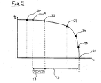
- Figure 5 provides a representation of how a generator's status (y axis) deteriorates over a time period prior to a failure event (x axis).
- Point 20 indicates the start of when damage to the wedges begins.
- the wedge damage has progressed to a sufficient extent that debris particles are present in the airflow within the generator's housing 8.
- point 22 where one or more of the wedges are able to vibrate within their slots. From here, deterioration of the generator's status begins to accelerate more rapidly, with vibrational noise being produced at point 23, followed by heat at point 24, and smoke at point 25. Eventually, the generator will fail entirely at point 26.
- the accumulation of particulate debris may be monitored in real-time while the generator 7 is operating.
- the processor 10 may use the output from sensor 9 to identify the presence of debris in the circulating air within the generator 7 from point 21 in Figure 5 onwards.
- the processor 10 may monitor the accumulation of this debris for identifying when a predetermined threshold is reached or the rate of accumulation of debris begins to accelerate. This may then initiate an alert to indicate that a potential fault has been identified.
- the processor 10 may automatically generate this early fault alert.
- the processor 10 may provide a user with a measurement value or graphical representation for their manual interpretation.
- embodiments of the present invention allow for early identification of wedge loosening so that a maintenance operation may be pre-emptively triggered.
- the debris accumulation threshold is set so that the early warning is triggered during a pre-warning window 28 shown in Figure 5 .
- This pre-warning window 28 is after point 21 where debris is present in the circulating air, but prior to point 22 where wedge vibrations are present.
- This allows early fault detection by a period corresponding to pre-warning time 27, which in practice may be around 3-6 months, and potentially up to 12 months in advance.
- a maintenance operation can be scheduled to allow the main generator components to be exchanged before they deteriorate to the extent that they could fail.
- the debris sensor is provided in the end plate of the generator housing, the sensor may be located in other locations.
- the debris sensor may be located in an airflow outlet of the generator. That is, the senor may be placed in the exhaust from an air-cooling arrangement.
- the debris sensor may be located in the airflow re-circulation circuit.
Landscapes
- Chemical & Material Sciences (AREA)
- Engineering & Computer Science (AREA)
- Life Sciences & Earth Sciences (AREA)
- Health & Medical Sciences (AREA)
- Immunology (AREA)
- Electrochemistry (AREA)
- Analytical Chemistry (AREA)
- Biochemistry (AREA)
- General Health & Medical Sciences (AREA)
- General Physics & Mathematics (AREA)
- Physics & Mathematics (AREA)
- Pathology (AREA)
- Chemical Kinetics & Catalysis (AREA)
- Sustainable Development (AREA)
- Sustainable Energy (AREA)
- Combustion & Propulsion (AREA)
- Mechanical Engineering (AREA)
- General Engineering & Computer Science (AREA)
- Wind Motors (AREA)
Priority Applications (3)
| Application Number | Priority Date | Filing Date | Title |
|---|---|---|---|
| EP20179579.6A EP3922847A1 (fr) | 2020-06-11 | 2020-06-11 | Procédé et système de détection précoce de défauts dans un générateur d'éolienne |
| EP21178071.3A EP3922848A1 (fr) | 2020-06-11 | 2021-06-07 | Procédé et système de détection précoce de défauts dans un générateur d'éolienne |
| US17/344,647 US20210389276A1 (en) | 2020-06-11 | 2021-06-10 | Method and system for early fault detection in a wind turbine generator |
Applications Claiming Priority (1)
| Application Number | Priority Date | Filing Date | Title |
|---|---|---|---|
| EP20179579.6A EP3922847A1 (fr) | 2020-06-11 | 2020-06-11 | Procédé et système de détection précoce de défauts dans un générateur d'éolienne |
Publications (1)
| Publication Number | Publication Date |
|---|---|
| EP3922847A1 true EP3922847A1 (fr) | 2021-12-15 |
Family
ID=71094091
Family Applications (2)
| Application Number | Title | Priority Date | Filing Date |
|---|---|---|---|
| EP20179579.6A Withdrawn EP3922847A1 (fr) | 2020-06-11 | 2020-06-11 | Procédé et système de détection précoce de défauts dans un générateur d'éolienne |
| EP21178071.3A Pending EP3922848A1 (fr) | 2020-06-11 | 2021-06-07 | Procédé et système de détection précoce de défauts dans un générateur d'éolienne |
Family Applications After (1)
| Application Number | Title | Priority Date | Filing Date |
|---|---|---|---|
| EP21178071.3A Pending EP3922848A1 (fr) | 2020-06-11 | 2021-06-07 | Procédé et système de détection précoce de défauts dans un générateur d'éolienne |
Country Status (2)
| Country | Link |
|---|---|
| US (1) | US20210389276A1 (fr) |
| EP (2) | EP3922847A1 (fr) |
Citations (4)
| Publication number | Priority date | Publication date | Assignee | Title |
|---|---|---|---|---|
| US3972225A (en) * | 1973-12-19 | 1976-08-03 | Westinghouse Electric Corporation | Sampling system for power generators |
| US4080535A (en) * | 1976-08-17 | 1978-03-21 | Westinghouse Electric Corporation | Generator condition monitor for particulate detection |
| US6456095B1 (en) * | 2000-06-28 | 2002-09-24 | Mitsubishi Denki Kabushiki Kaisha | Generator interior cooling gas monitor and monitor system |
| US20080191891A1 (en) * | 2005-08-04 | 2008-08-14 | Siemens Power Generation, Inc. | Power generator and power generator auxiliary monitoring |
Family Cites Families (4)
| Publication number | Priority date | Publication date | Assignee | Title |
|---|---|---|---|---|
| TW201402940A (zh) * | 2012-02-08 | 2014-01-16 | Romo Wind Ag | 用於調整風力機之橫擺的裝置 |
| ES2613902B1 (es) * | 2015-11-26 | 2018-03-14 | Gamesa Innovation & Technology, S.L. | Método y sistemas de monitorización en tiempo real del estado del aislamiento de los devanados de generadores eólicos |
| US11300106B2 (en) * | 2018-07-18 | 2022-04-12 | Poseidon Systems, LLC | System and method for utilizing wear debris sensor to reduce damage and extend remaining useful life of gearboxes |
| US11168668B2 (en) * | 2019-06-24 | 2021-11-09 | Mistras Group, Inc. | Wind turbine blade monitoring systems |
-
2020
- 2020-06-11 EP EP20179579.6A patent/EP3922847A1/fr not_active Withdrawn
-
2021
- 2021-06-07 EP EP21178071.3A patent/EP3922848A1/fr active Pending
- 2021-06-10 US US17/344,647 patent/US20210389276A1/en active Pending
Patent Citations (4)
| Publication number | Priority date | Publication date | Assignee | Title |
|---|---|---|---|---|
| US3972225A (en) * | 1973-12-19 | 1976-08-03 | Westinghouse Electric Corporation | Sampling system for power generators |
| US4080535A (en) * | 1976-08-17 | 1978-03-21 | Westinghouse Electric Corporation | Generator condition monitor for particulate detection |
| US6456095B1 (en) * | 2000-06-28 | 2002-09-24 | Mitsubishi Denki Kabushiki Kaisha | Generator interior cooling gas monitor and monitor system |
| US20080191891A1 (en) * | 2005-08-04 | 2008-08-14 | Siemens Power Generation, Inc. | Power generator and power generator auxiliary monitoring |
Non-Patent Citations (1)
| Title |
|---|
| EONEUTILITYSYSTEMS: "E/One Generator Condition Monitor for Air-Cooled Generators (GCM-A)", YOUTUBE, 20 February 2013 (2013-02-20), pages 1, XP054981075, Retrieved from the Internet <URL:https://www.youtube.com/watch?v=qu-tgCevi2g> [retrieved on 20201104] * |
Also Published As
| Publication number | Publication date |
|---|---|
| EP3922848A1 (fr) | 2021-12-15 |
| US20210389276A1 (en) | 2021-12-16 |
Similar Documents
| Publication | Publication Date | Title |
|---|---|---|
| EP2665925B1 (fr) | Procédé pour diagnostique le monitorage d'un système de générateur d'éolienne | |
| US10473708B2 (en) | Methods and systems for real-time monitoring of the insulation state of wind-powered generator windings | |
| CN103998775A (zh) | 用于确定风能源设备的转子叶片的机械损坏的方法 | |
| KR20110072123A (ko) | 설비 구동부 고장 감시 장치 | |
| Iorgulescu et al. | Vibration monitoring for diagnosis of electrical equipment's faults | |
| Tetreault et al. | End-winding vibration monitoring: Pivotal in preventing major damage on a large turbo-generator | |
| EP3922847A1 (fr) | Procédé et système de détection précoce de défauts dans un générateur d'éolienne | |
| Yang et al. | Starting current analysis in medium voltage induction motors: Detecting rotor faults and reactor starting defects | |
| JP6714844B2 (ja) | 異常診断方法 | |
| JP2019507845A (ja) | 風力発電システムの振動状態を監視する方法 | |
| JP5584002B2 (ja) | 巻線絶縁の劣化診断方法及び巻線絶縁の劣化診断装置 | |
| Almounajjed et al. | Condition monitoring and fault diagnosis of induction motor-an experimental analysis | |
| US20230366383A1 (en) | Wind turbine monitoring device, wind turbine system, and wind turbine monitoring method | |
| CN108267504B (zh) | 一种铁磁性发动机壳体内叶片动态原位监测方法 | |
| Haq et al. | Understanding Alternative Methods of Machine Online Condition Monitoring; An Investigation Based on Years of Experience and Field Case Studies | |
| KR100905971B1 (ko) | 발전-전동기 운전중 진단 시스템 및 방법 | |
| Yang et al. | Starting current analysis for condition monitoring of medium voltage induction motors in the steel industry | |
| Thomson et al. | On-line diagnostics of large induction motors | |
| He et al. | Remote monitoring and diagnostics of blade health in commercial MW-scale wind turbines using electrical signature analysis (ESA) | |
| RU90199U1 (ru) | Устройство диагностики электродвигателей переменного тока и связанного с ними механического оборудования | |
| Zhang et al. | Electrical signature analysis based condition monitoring and diagnostics techniques for wind turbines | |
| Tan et al. | Wind turbine monitoring warning device | |
| Yang et al. | Starting Current Analysis in Medium Voltage Induction Motors | |
| Bertheau et al. | Permanent on-line partial discharge monitoring as strategic concept to condition based diagnosis and maintenance | |
| De Silva | Survey of Condition Monitoring Techniques for Induction Motors |
Legal Events
| Date | Code | Title | Description |
|---|---|---|---|
| PUAI | Public reference made under article 153(3) epc to a published international application that has entered the european phase |
Free format text: ORIGINAL CODE: 0009012 |
|
| STAA | Information on the status of an ep patent application or granted ep patent |
Free format text: STATUS: THE APPLICATION HAS BEEN PUBLISHED |
|
| AK | Designated contracting states |
Kind code of ref document: A1 Designated state(s): AL AT BE BG CH CY CZ DE DK EE ES FI FR GB GR HR HU IE IS IT LI LT LU LV MC MK MT NL NO PL PT RO RS SE SI SK SM TR |
|
| B565 | Issuance of search results under rule 164(2) epc |
Effective date: 20201113 |
|
| STAA | Information on the status of an ep patent application or granted ep patent |
Free format text: STATUS: THE APPLICATION IS DEEMED TO BE WITHDRAWN |
|
| 18D | Application deemed to be withdrawn |
Effective date: 20220616 |