EP3922820B1 - Turbinenleitapparat - Google Patents
Turbinenleitapparat Download PDFInfo
- Publication number
- EP3922820B1 EP3922820B1 EP21177397.3A EP21177397A EP3922820B1 EP 3922820 B1 EP3922820 B1 EP 3922820B1 EP 21177397 A EP21177397 A EP 21177397A EP 3922820 B1 EP3922820 B1 EP 3922820B1
- Authority
- EP
- European Patent Office
- Prior art keywords
- shroud
- carrier
- stator blade
- projection
- stator
- Prior art date
- Legal status (The legal status is an assumption and is not a legal conclusion. Google has not performed a legal analysis and makes no representation as to the accuracy of the status listed.)
- Active
Links
Images

Classifications
-
- F—MECHANICAL ENGINEERING; LIGHTING; HEATING; WEAPONS; BLASTING
- F01—MACHINES OR ENGINES IN GENERAL; ENGINE PLANTS IN GENERAL; STEAM ENGINES
- F01D—NON-POSITIVE DISPLACEMENT MACHINES OR ENGINES, e.g. STEAM TURBINES
- F01D11/00—Preventing or minimising internal leakage of working-fluid, e.g. between stages
- F01D11/08—Preventing or minimising internal leakage of working-fluid, e.g. between stages for sealing space between rotor blade tips and stator
- F01D11/14—Adjusting or regulating tip-clearance, i.e. distance between rotor-blade tips and stator casing
- F01D11/20—Actively adjusting tip-clearance
- F01D11/22—Actively adjusting tip-clearance by mechanically actuating the stator or rotor components, e.g. moving shroud sections relative to the rotor
-
- F—MECHANICAL ENGINEERING; LIGHTING; HEATING; WEAPONS; BLASTING
- F01—MACHINES OR ENGINES IN GENERAL; ENGINE PLANTS IN GENERAL; STEAM ENGINES
- F01D—NON-POSITIVE DISPLACEMENT MACHINES OR ENGINES, e.g. STEAM TURBINES
- F01D9/00—Stators
- F01D9/02—Nozzles; Nozzle boxes; Stator blades; Guide conduits, e.g. individual nozzles
- F01D9/04—Nozzles; Nozzle boxes; Stator blades; Guide conduits, e.g. individual nozzles forming ring or sector
- F01D9/042—Nozzles; Nozzle boxes; Stator blades; Guide conduits, e.g. individual nozzles forming ring or sector fixing blades to stators
-
- F—MECHANICAL ENGINEERING; LIGHTING; HEATING; WEAPONS; BLASTING
- F01—MACHINES OR ENGINES IN GENERAL; ENGINE PLANTS IN GENERAL; STEAM ENGINES
- F01D—NON-POSITIVE DISPLACEMENT MACHINES OR ENGINES, e.g. STEAM TURBINES
- F01D9/00—Stators
- F01D9/02—Nozzles; Nozzle boxes; Stator blades; Guide conduits, e.g. individual nozzles
- F01D9/04—Nozzles; Nozzle boxes; Stator blades; Guide conduits, e.g. individual nozzles forming ring or sector
- F01D9/041—Nozzles; Nozzle boxes; Stator blades; Guide conduits, e.g. individual nozzles forming ring or sector using blades
-
- F—MECHANICAL ENGINEERING; LIGHTING; HEATING; WEAPONS; BLASTING
- F01—MACHINES OR ENGINES IN GENERAL; ENGINE PLANTS IN GENERAL; STEAM ENGINES
- F01D—NON-POSITIVE DISPLACEMENT MACHINES OR ENGINES, e.g. STEAM TURBINES
- F01D17/00—Regulating or controlling by varying flow
- F01D17/10—Final actuators
- F01D17/12—Final actuators arranged in stator parts
- F01D17/14—Final actuators arranged in stator parts varying effective cross-sectional area of nozzles or guide conduits
- F01D17/16—Final actuators arranged in stator parts varying effective cross-sectional area of nozzles or guide conduits by means of nozzle vanes
-
- F—MECHANICAL ENGINEERING; LIGHTING; HEATING; WEAPONS; BLASTING
- F01—MACHINES OR ENGINES IN GENERAL; ENGINE PLANTS IN GENERAL; STEAM ENGINES
- F01D—NON-POSITIVE DISPLACEMENT MACHINES OR ENGINES, e.g. STEAM TURBINES
- F01D25/00—Component parts, details, or accessories, not provided for in, or of interest apart from, other groups
-
- F—MECHANICAL ENGINEERING; LIGHTING; HEATING; WEAPONS; BLASTING
- F01—MACHINES OR ENGINES IN GENERAL; ENGINE PLANTS IN GENERAL; STEAM ENGINES
- F01D—NON-POSITIVE DISPLACEMENT MACHINES OR ENGINES, e.g. STEAM TURBINES
- F01D25/00—Component parts, details, or accessories, not provided for in, or of interest apart from, other groups
- F01D25/24—Casings; Casing parts, e.g. diaphragms, casing fastenings
- F01D25/246—Fastening of diaphragms or stator-rings
-
- F—MECHANICAL ENGINEERING; LIGHTING; HEATING; WEAPONS; BLASTING
- F05—INDEXING SCHEMES RELATING TO ENGINES OR PUMPS IN VARIOUS SUBCLASSES OF CLASSES F01-F04
- F05D—INDEXING SCHEME FOR ASPECTS RELATING TO NON-POSITIVE-DISPLACEMENT MACHINES OR ENGINES, GAS-TURBINES OR JET-PROPULSION PLANTS
- F05D2220/00—Application
- F05D2220/30—Application in turbines
- F05D2220/32—Application in turbines in gas turbines
-
- F—MECHANICAL ENGINEERING; LIGHTING; HEATING; WEAPONS; BLASTING
- F05—INDEXING SCHEMES RELATING TO ENGINES OR PUMPS IN VARIOUS SUBCLASSES OF CLASSES F01-F04
- F05D—INDEXING SCHEME FOR ASPECTS RELATING TO NON-POSITIVE-DISPLACEMENT MACHINES OR ENGINES, GAS-TURBINES OR JET-PROPULSION PLANTS
- F05D2230/00—Manufacture
- F05D2230/60—Assembly methods
- F05D2230/64—Assembly methods using positioning or alignment devices for aligning or centring, e.g. pins
-
- F—MECHANICAL ENGINEERING; LIGHTING; HEATING; WEAPONS; BLASTING
- F05—INDEXING SCHEMES RELATING TO ENGINES OR PUMPS IN VARIOUS SUBCLASSES OF CLASSES F01-F04
- F05D—INDEXING SCHEME FOR ASPECTS RELATING TO NON-POSITIVE-DISPLACEMENT MACHINES OR ENGINES, GAS-TURBINES OR JET-PROPULSION PLANTS
- F05D2240/00—Components
- F05D2240/10—Stators
- F05D2240/12—Fluid guiding means, e.g. vanes
-
- F—MECHANICAL ENGINEERING; LIGHTING; HEATING; WEAPONS; BLASTING
- F05—INDEXING SCHEMES RELATING TO ENGINES OR PUMPS IN VARIOUS SUBCLASSES OF CLASSES F01-F04
- F05D—INDEXING SCHEME FOR ASPECTS RELATING TO NON-POSITIVE-DISPLACEMENT MACHINES OR ENGINES, GAS-TURBINES OR JET-PROPULSION PLANTS
- F05D2260/00—Function
- F05D2260/30—Retaining components in desired mutual position
-
- F—MECHANICAL ENGINEERING; LIGHTING; HEATING; WEAPONS; BLASTING
- F05—INDEXING SCHEMES RELATING TO ENGINES OR PUMPS IN VARIOUS SUBCLASSES OF CLASSES F01-F04
- F05D—INDEXING SCHEME FOR ASPECTS RELATING TO NON-POSITIVE-DISPLACEMENT MACHINES OR ENGINES, GAS-TURBINES OR JET-PROPULSION PLANTS
- F05D2260/00—Function
- F05D2260/30—Retaining components in desired mutual position
- F05D2260/31—Retaining bolts or nuts
Definitions
- the invention relates to a turbine nozzle.
- a turbine nozzle is a stator-side assembly that has several guide blades or guide blade segments, each consisting of several guide blades and carriers for fastening or supporting the guide blades or guide blade segments. These carriers for fastening or supporting the guide vanes are also referred to as guide vane carriers or guide vane segment carriers.
- the respective guide vanes typically have shrouds, namely a first shroud and a second shroud, which are formed on opposite radial ends of an airfoil of the guide blades.
- a radially inner shroud is also called an inner shroud and a radially outer shroud is also called an outer shroud.
- the guide vanes or guide vane segments are attached or supported on the carriers at their radial ends, namely via their shrouds, with each guide vane or each guide vane segment attached or supported on a first carrier in the area of the first shroud and on a second carrier in the area of the second shroud is.
- the US 8,356,981 B2 discloses a gas turbine with a turbine nozzle.
- the turbine nozzle has several guide vanes, with each guide vane having an inner shroud radially on the inside and an outer shroud radially on the outside.
- a projection is formed on the inner shroud, which engages in a groove on the inner support for the guide vanes.
- a projection is also formed on the outer shroud, which engages in a groove in the outer support for the guide vanes.
- a spherical contour is formed on this projection of the outer cover strip, with which the projection is supported on an axial surface of the groove of the outer carrier.
- the present invention is based on the object of creating a new type of turbine guide apparatus.
- the object is achieved by a turbine nozzle according to claim 1.
- the projection of the first shroud of the respective guide vane or the respective guide vane segment is inserted into a groove of the first carrier in the radial direction, supported via a spherically contoured axial surface section on an axial surface of the groove of the first carrier and further in this groove via a groove extending in the axial direction through the
- the projection of the first shroud is fastened and supported in the circumferential direction with radial mobility in this groove, whereby, viewed in the axial direction, there is axial play between the projection of the first shroud of the respective guide vane or the respective guide vane segment and the groove of the first carrier.
- the projection of the second shroud of the respective guide vane or the respective guide vane segment is supported on an axial surface of the second carrier via a spherically contoured axial surface section (25) and further in the circumferential direction via a pin which extends in the axial direction into the projection of the second shroud and the second carrier and radial direction attached and supported.
- This allows a particularly advantageous attachment and support and thus suspension of the guide vanes or guide vane segments on the supports of the turbine nozzle.
- Thermomechanical deformations of the supports of the turbine nozzle do not result in additional loading of the guide blades or guide blade segments.
- the forces acting on the guide vanes or vane segments can be optimally transferred to the carrier.
- the respective bolt extends in the axial direction through a slot in the projection of the first shroud that is open in the radial direction and through the first carrier. This makes it possible to ensure the radial mobility of the respective guide vane or the respective guide vane segment relative to the first carrier in a particularly simple manner.
- the respective pin preferably has a cylindrically contoured outer wall on a section of the same which extends in the axial direction into the second carrier, the respective pin on a section of the same which extends in the axial direction into the second shroud of the respective guide vane or the respective Guide vane segment extends into it, has a torus-like or spherical head-shaped outer wall. This makes it easy to ensure that the respective guide vane or the respective guide vane segment can tilt or tilt relative to the second shroud as a result of thermal-mechanical deformation.
- the respective spherically contoured axial surface section of the respective guide vane or the respective guide vane segment preferably runs in a straight line, at least in sections, when viewed in the circumferential direction.
- the respective spherically contoured axial surface section is particularly preferred for sealing the respective shroud of the respective guide vane or the respective guide vane segment relative to the respective carrier. Even if, for example, as a result of thermal-mechanical deformation, the respective guide vane or the respective guide vane segment should tilt or tilt relative to the respective carrier, a tightness between the respective shroud and the respective carrier can be ensured. Leaks through the shrouds can be avoided in this way.
- a slot is introduced into the respective spherically contoured axial surface section of the respective guide vane or the respective guide vane segment at one circumferential end, which, together with a corresponding slot of a guide vane or a guide vane segment adjoining in the circumferential direction, delimits a groove which receives a sealing plate. This allows the tightness of the suspension of the guide vanes or guide vane segments on the respective carrier to be further improved.
- the invention relates to a turbine nozzle 10, in particular a gas turbine.
- a turbine nozzle 10 has several guide blades 11 or several guide blade segments each made up of several guide blades 11.
- Fig. 1 shows a cross section through a turbine nozzle 10 in the area of such a guide blade 11, in the area of a first carrier 12 and in the area of a second carrier 13 for the guide blades 11.
- the carriers 12, 13 are also referred to as guide vane carriers.
- the respective guide vane 11 of the turbine nozzle 10 has a blade 14 with flow-guiding surfaces 15, 16.
- shrouds are formed at radially opposite ends of the blade 14, namely a first shroud 17 and a second shroud 18.
- each guide vane 11 is attached and supported on the first carrier 12 via its first shroud 17. Furthermore, each guide vane 11 is attached and supported on the second carrier 13 via its second shroud 18.
- the first shroud 17 is a radially inner shroud, hereinafter referred to as the inner shroud, of the guide vane 11 and the first carrier 12 is an internal carrier to which the guide vane 11 is attached and supported.
- the second shroud 18 is in Fig. 1 around a radially outer shroud, hereinafter referred to as the outer shroud, and in the second carrier 13 around a radially outer carrier to which the guide vane 11 is attached and supported.
- the respective guide vane 11 points on the first shroud 17, i.e. in Fig. 1 on the inner shroud, a projection 17a, which is inserted in the radial direction R into a groove 19 of the first carrier 12 and in this groove 19 of the first carrier 12 via a bolt 20 extending in the axial direction A through the projection 17a and through the carrier 12 radial translational mobility within this groove 19 in the circumferential direction U is fastened and supported.
- a projection 18a is formed, via which the respective guide vane 11 is fastened and supported on the second carrier 13, namely in such a way that a pin 21 extending in the axial direction A is on the one hand in the Projection 18a of the second shroud 18 and on the other hand extends into the second carrier 13 and the guide vane 11 is fastened and supported on the second carrier 13 in the circumferential direction U and radial direction R.
- the pin 21 can also be referred to as a pin.
- the respective guide vane 11 is therefore fastened and supported via its second shroud 18 and via the respective pin 21 in the circumferential direction U and radial direction R, so that in the circumferential direction U and radial direction pure translational movement of the guide vane 11 relative to the second carrier 13 is prohibited.
- the guide vane 11 is fastened and supported in the circumferential direction U via the projection 17a of the first shroud 17, namely via the bolt 20, which extends in the axial direction A through the first carrier 12 and the projection 17a of the first shroud 17 respective guide vane 11 extends.
- the respective guide vane 11 is therefore fixed in the circumferential direction U, but not in the radial direction R, so that a radial translational mobility of the guide vane 11 relative to the first carrier 12 is possible here.
- the pin 21 has a section 21a which extends into the recess 22 of the projection 18a of the second shroud 18 of the respective guide vane 11, the pin 21 having a torus-like or spherical head-like contoured outer wall 21c on this section 21a having.
- the section 21b At an end of the section 21b facing away from the section 21a, the section 21b has a conically tapering outer wall 21e in order to be able to insert the pin 21 more easily into the recess 23 of the second carrier 13.
- the guide vane 11 is fastened to its first shroud 17 on the first carrier 12 in that the projection 17a of the first shroud 17 protrudes in the radial direction R into the groove 19 of the first carrier 12 and there via a bolt 20 in Circumferential direction U is attached and supported, which extends as seen in the axial direction A through the first carrier 12 and the projection 17a of the first shroud 17.
- 7 and 8 show detailed views of such a bolt 20.
- a central section 20a of the bolt 20 acts in the groove 19 of the first carrier 12 projecting projection 17a together in such a way that the radial translational mobility of the guide blade 11 in the groove 19 is given relative to the first carrier 12.
- the bolt 20 extends in the axial direction A through a slot 29 of the projection 17a that is open in the radial direction R, the bolt 20 being dimensioned in section 20a such that the radial translational mobility of the guide vane 11 relative to the first carrier 12 is both radially inward and is also possible radially outwards.
- This middle section 20a of the bolt 20 is adjoined on both sides by lateral sections 20b and 20c, via which the bolt is fixed in a recess in the first carrier 12.
- a shoulder 20d formed on section 20b limits the insertion depth of the respective bolt 20 into the first carrier 12 and ensures exact relative positioning between the section 20a of the respective bolt 20 and the projection 17a on the first shroud 17 of the respective guide vane 11.
- the groove 29 in Projection 17a of the first shroud 17 fixes the axial position of the bolt 20 via flanks of the section 20a of the bolt 20.
- the respective guide vane 11 can translate relative to the first carrier 12 in the radial direction R, in particular as a result of thermomechanical deformations.
- the respective shroud 11 is fastened to the second carrier 13 via the above described pin 21, a translational displacement in the radial direction R is excluded, as is a translational displacement in the circumferential direction U.
- the fact that the pin 21 has the torus-like or spherical head-like contoured outer wall 21c on section 21 means that the respective guide vane 11 can tilt relative to the second carrier 13 and This also makes the first carrier 12 possible.
- the projection 17a of the first shroud 17 as well the projection 18a of the second shroud 18 has a spherically contoured axial surface section 24, 25 on.
- the spherically contoured axial surface section 24 of the projection 17a of the first shroud 12 comes into contact with and is supported on an axial surface of the groove 19 of the first carrier 12 and the spherically contoured axial surface section 25 of the projection 18a of the second shroud 18 comes into contact with and is supported on an axial surface of the second carrier 13.
- these spherically contoured axial surface sections 24, 25 roll on the adjacent axial surface of the groove 19 of the first carrier 12 or the adjacent axial surface of the second carrier 13 and thus ensure a Tight suspension of the respective guide vane 11 in the area of its respective shroud 17, 18 on the respective carrier 12, 13.
- Figs. 2 and 3 show this rolling movement for the projection 17a on the first shroud 17 relative to the first carrier 12.
- the guide vane 11 is not tilted.
- the guide vane 11 is tilted in different directions, namely in Fig. 2 clockwise and in Fig. 4 counterclockwise.
- the respective spherically contoured axial surface section 24 extends at least in sections in a straight line, namely in Fig. 9 continuously straight across the respective section 17a and thus tangential to the circumferential direction U.
- the spherically contoured axial surface sections 24 of adjacent guide vanes 11 form a polygon.
- a slot 26 is made in the spherically contoured axial surface section 24 of the projection 17a of the first shroud 17 of the respective guide vane in the area of each circumferential end of the respective projection 17a.
- Such slots 26 for forming the grooves 27, which serve to accommodate a sealing plate 28, are preferably formed not only in the spherically contoured axial surface sections 24 on section 17a of the first shroud 17, but preferably also on the spherically contoured axial surface section 25 of the projection 18a of the second Shrouds 18 of the respective guide vane 11.
- the turbine nozzle 10 according to the invention is characterized by a completely new type of attachment, support and sealing of guide blades 11 on the supports 12, 13 of the turbine nozzle 10.
- Thermomechanical deformations, especially in the area of the supports 12, 13, do not result in additional blade loading.
- a translational relative movement and a tilting of the respective guide vane 11 relative to the carriers 12, 13 is possible.
- a tightness of the suspension of the respective guide vane on the respective carrier 12, 13 is still ensured. Forces acting on the guide vanes 11 can be diverted to both carriers 12, 13 via both shrouds 17, 18.
Landscapes
- Engineering & Computer Science (AREA)
- Mechanical Engineering (AREA)
- General Engineering & Computer Science (AREA)
- Turbine Rotor Nozzle Sealing (AREA)
Description
- Die Erfindung betrifft einen Turbinenleitapparat.
- Gasturbinen verfügen über Turbinenleitapparate. Bei einem Turbinenleitapparat handelt es sich um eine statorseitige Baugruppe, die mehrere Leitschaufeln oder Leitschaufelsegmente aus jeweils mehreren Leitschaufeln und Träger zur Befestigung oder Abstützung der Leitschaufeln oder Leitschaufelsegmente aufweist. Diese Träger zur Befestigung oder Abstützung der Leitschaufeln werden auch als Leitschaufelträger oder Leitschaufelsegmentträger bezeichnet. Die jeweiligen Leitschaufeln verfügen typischerweise über Deckbänder, nämlich ein erstes Deckband und ein zweites Deckband, die an sich gegenüberliegenden radialen Enden eines Schaufelblatts der Leitschaufeln ausgebildet sind. Ein radial inneres Deckband wird auch als Innendeckband und ein radial äußeres Deckband auch als Außendeckband bezeichnet. Die Leitschaufeln oder Leitschaufelsegmente sind an ihren radialen Enden, nämlich über ihre Deckbänder, an den Trägern befestigt oder abgestützt, wobei jede Leitschaufel oder jedes Leitschaufelsegmente an einem ersten Träger im Bereich des ersten Deckbands und an einem zweiten Träger im Bereich des zweiten Deckbands befestigt oder abgestützt ist.
- Die
US 8 356 981 B2 offenbart eine Gasturbine mit einem Turbinenleitapparat. Der Turbinenleitapparat verfügt über mehrere Leitschaufeln, wobei jede Leitschaufel radial innen ein Innendeckband und radial außen ein Außendeckband aufweist. Am Innendeckband ist ein Vorsprung ausgebildet, der in eine Nut am inneren Träger für die Leitschaufeln eingreift. Am Außendeckband ist ebenfalls ein Vorsprung ausgebildet, der in eine Nut des äußeren Trägers für die Leitschaufeln eingreift. An diesem Vorsprung des Außendeckbands ist eine ballige Kontur ausgebildet, mit welcher sich der Vorsprung an einer Axialfläche der Nut des äußeren Trägers abstützt. - Weitere Gasturbinen mit Leitschaufelträgern sind aus der
US 8 356 975 B2 und aus derUS 7 926 289 B2 bekannt.US 4 017 213 A offenbart einen Turbinenleitapparat nach dem Oberbegriff des Anspruchs 1.US 4 720 236 A offenbart einen weiteren Turbinenleitapparat. Aus TurbinenleitapparateEP 3 299 584 A1 und ausUS 2006 / 0 062 673 A1 sind weitere Leitapparate bekannt. - Es besteht Bedarf daran, an einem Turbinenleitapparat die Befestigung bzw. Abstützung der Leitschaufeln oder Leitschaufelsegmente an den Trägern des Turbinenleitapparats und vorzugsweise auch die Abdichtung der Leitschaufeln oder Leitschaufelsegmente an den Trägern des Turbinenleitapparats zu verbessern. Hiervon ausgehend liegt der vorliegenden Erfindung die Aufgabe zugrunde, einen neuartigen Turbinenleitapparat zu schaffen.
- Nach der Erfindung wird die Aufgabe durch einen Turbinenleitapparat nach Anspruch 1 gelöst. Erfindungsgemäß ist der Vorsprung des ersten Deckbands der jeweiligen Leitschaufel oder des jeweiligen Leitschaufelsegments in eine Nut des ersten Trägers in Radialrichtung eingesetzt, über einen ballig konturierten Axialflächenabschnitt an einer Axialfläche der Nut des ersten Trägers abgestützt und ferner in dieser Nut über einen sich in Axialrichtung durch den Vorsprung des ersten Deckbands hindurch ersteckenden Bolzen bei radialer Beweglichkeit in dieser Nut in Umfangsrichtung befestigt und abgestützt, wobei in Axialrichtung gesehen zwischen dem Vorsprung des ersten Deckbands der jeweiligen Leitschaufel oder des jeweiligen Leitschaufelsegments und der Nut des ersten Trägers ein Axialspiel besteht. Der Vorsprung des zweiten Deckbands der jeweiligen Leitschaufel oder des jeweiligen Leitschaufelsegments ist über einen ballig konturierten Axialflächenabschnitt (25) an einer Axialfläche des zweiten Trägers abgestützt und ferner über einen sich in Axialrichtung in den Vorsprung des zweiten Deckbands und den zweiten Träger hinein ersteckenden Stift in Umfangsrichtung und Radialrichtung befestigt und abgestützt. Dies erlaubt eine besonders vorteilhafte Befestigung und Abstützung und damit Aufhängung der Leitschaufeln oder Leitschaufelsegmente an den Trägern des Turbinenleitapparats. Thermomechanische Verformungen der Träger des Turbinenleitapparats resultieren nicht in einer zusätzlichen Belastung der Leitschaufeln oder Leitschaufelsegmente. Im Betrieb auf die Leitschaufeln oder Leitschaufelsegmente wirkende Kräfte können optimal an die Träger abgeleitet werden.
- Vorzugsweise erstreckt sich der jeweilige Bolzen in Axialrichtung durch einen in Radialrichtung offenen Schlitz des Vorsprungs des ersten Deckbands und durch den ersten Träger. Hiermit kann auf besonders einfache Art und Weise die radiale Beweglichkeit der jeweiligen Leitschaufel oder des jeweiligen Leitschaufelsegments relativ zum ersten Träger gewährleistet werden.
- Vorzugsweise weist der jeweilige Stift an einem Abschnitt desselben, der sich in Axialrichtung in den zweiten Träger hinein erstreckt, eine zylinderartig konturierte Außenwand auf, wobei der jeweilige Stift an einem Abschnitt desselben, der sich in Axialrichtung in das zweite Deckband der jeweiligen Leitschaufel oder des jeweiligen Leitschaufelsegments hinein hinein erstreckt, eine torusartig oder kugelkopfartig konturierte Außenwand aufweist. Hierdurch kann einfach sichergestellt werden, dass die jeweilige Leitschaufel oder das jeweilige Leitschaufelsegment infolge einer thermisch-mechanischen Verformung gegenüber dem zweiten Deckband kippen oder verkippen kann.
- Der jeweilige ballig konturierte Axialflächenabschnitt der jeweiligen Leitschaufel oder des jeweiligen Leitschaufelsegments verläuft vorzugsweis in Umfangsrichtung gesehen zumindest abschnittweise geradlinig. Der jeweilig ballig konturierte Axialflächenabschnitt ist für eine Abdichtung des jeweiligen Deckbands der jeweiligen Leitschaufel oder des jeweiligen Leitschaufelsegments gegenüber dem jeweiligen Träger besonders bevorzugt. Auch dann, wenn zum Beispiel infolge einer thermisch-mechanischen Verformung die jeweilige Leitschaufel oder des jeweiligen Leitschaufelsegments sich gegenüber dem jeweiligen Träger kippen oder verkippen sollte, kann so eine Dichtheit zwischen dem jeweiligen Deckband und dem jeweiligen Träger gewährleistet werden. Leckagen über die Deckbänder können so vermieden werden.
- Vorzugsweise ist in den jeweiligen ballig konturierten Axialflächenabschnitt der jeweiligen Leitschaufel oder des jeweiligen Leitschaufelsegments an einem Umfangsende ein Schlitz einbracht, der zusammen mit einem entsprechenden Schlitz einer sich in Umfangsrichtung anschließenden Leitschaufel oder eines sich in Umfangsrichtung anschließenden Leitschaufelsegments eine Nut begrenzt, die ein Dichtblech aufnimmt. Hiermit kann die Dichtheit der Aufhängung der Leitschaufeln oder Leitschaufelsegmente am jeweiligen Träger weiter verbessert werden.
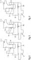
- Bevorzugte Weiterbildungen der Erfindung ergeben sich aus den Unteransprüchen und der nachfolgenden Beschreibung. Ausführungsbeispiele der Erfindung werden, ohne hierauf beschränkt zu sein, an Hand der Zeichnung näher erläutert. Dabei zeigt:
- Fig. 1
- einen Querschnitt durch einen Turbinenleitapparat;
- Fig. 2
- ein Detail der
Fig. 1 in einem ersten Zustand, - Fig. 3
- das Detail der
Fig. 2 in einem zweiten Zustand, - Fig. 4
- das Detail der
Fig. 2 in einem dritten Zustand - Fig. 5
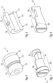
- eine perspektivische Ansicht eines Stifts,
- Fig. 6
- einen Querschnitt durch
Fig. 5 ; - Fig. 7
- eine perspektivische Ansicht eines Bolzens,
- Fig. 8
- einen Querschnitt durch
Fig. 7 ; - Fig. 9
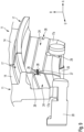
- eine perspektivische Ansicht eines ausschnittsweisen Querschnitts durch einen Turbinenleitapparat.
- Die Erfindung betrifft einen Turbinenleitapparat 10, insbesondere einer Gasturbine. Ein solcher Turbinenleitapparat 10 verfügt über mehrere Leitschaufeln 11 oder mehrere Leitschaufelsegmente aus jeweils mehreren Leitschaufeln 11.
-
Fig. 1 zeigt einen Querschnitt durch einen Turbinenleitapparat 10 im Bereich einer solchen Leitschaufel 11, im Bereich eines ersten Trägers 12 sowie im Bereich eines zweiten Trägers 13 für die Leitschaufeln 11. Die Träger 12, 13 werden auch als Leitschaufelträger bezeichnet. - Die jeweilige Leitschaufel 11 des Turbinenleitapparats 10 verfügt über ein Schaufelblatt 14 mit strömungsführenden Flächen 15, 16. An der Leitschaufel 11 sind an radial sich gegenüberliegenden Enden des Schaufelblatts 14 Deckbänder gebildet, nämlich ein erstes Deckband 17 und ein zweites Deckband 18.
- Die jeweilige Leitschaufel 11 ist über ihr erstes Deckband 17 am ersten Träger 12 befestigt und abgestützt. Ferner ist jede Leitschaufel 11 über ihr zweites Deckband 18 am zweiten Träger 13 befestigt und abgestützt.
- Im in
Fig. 1 gezeigten Ausführungsbeispiel handelt es sich beim ersten Deckband 17 um ein radial innen liegendes Deckband, nachfolgend Innendeckband genannt, der Leitschaufel 11 und beim ersten Träger 12 über einen innenliegenden Träger, an welchem die Leitschaufel 11 befestigt und abgestützt ist. Beim zweiten Deckband 18 handelt es sich inFig. 1 um ein radial außen liegendes Deckband, nachfolgend Außendeckband genannt, und beim zweiten Träger 13 um einen radial äußeren Träger, an welchem die Leitschaufel 11 befestigt und abgestützt ist. - Die jeweilige Leitschaufel 11 weist am ersten Deckband 17, also in
Fig. 1 am Innendeckband, einen Vorsprung 17a auf, der in Radialrichtung R in eine Nut 19 des ersten Trägers 12 eingesetzt ist und in dieser Nut 19 des ersten Trägers 12 über ein sich in Axialrichtung A durch den Vorsprung 17a sowie durch den Träger 12 erstreckenden Bolzen 20 bei radialer translatorischer Beweglichkeit innerhalb dieser Nut 19 in Umfangsrichtung U befestigt und abgestützt ist. - Am gegenüberliegenden zweiten Deckband 18, also im gezeigten Ausführungsbeispiel am Außendeckband 18, ist ein Vorsprung 18a ausgebildet, über welchen die jeweilige Leitschaufel 11 am zweiten Träger 13 befestigt und abgestützt ist, nämlich derart, dass ein sich in Axialrichtung A erstreckender Stift 21 einerseits in den Vorsprung 18a des zweiten Deckbands 18 und andererseits in den zweiten Träger 13 hinein erstreckt und die Leitschaufel 11 am zweiten Träger 13 in Umfangsrichtung U und Radialrichtung R befestigt und abstützt. Der Stift 21 kann auch als Pin bezeichnet werden.
- Im Bereich des zweiten Trägers 13 ist demnach die jeweilige Leitschaufel 11 über ihr zweites Deckband 18 und über den jeweiligen Stift 21 in Umfangsrichtung U und Radialrichtung R befestigt und abgestützt, sodass in Umfangsrichtung U und Radialrichtung Reine translatorische Bewegung der Leitschaufel 11 relativ zum zweiten Träger 13 unterbunden ist.
- Im Bereich des ersten Deckbands 17 ist die Leitschaufel 11 über den Vorsprung 17a des ersten Deckbands 17 in Umfangsrichtung U befestigt und abgestützt, nämlich über den Bolzen 20, der sich in Axialrichtung A durch den ersten Träger 12 und den Vorsprung 17a des ersten Deckbands 17 der jeweiligen Leitschaufel 11 erstreckt. Im Bereich des ersten Deckbands 17 ist die jeweilige Leitschaufel 11 demnach in Umfangsrichtung U festgelegt, jedoch nicht in Radialrichtung R, sodass hier eine radiale translatorische Beweglichkeit der Leitschaufel 11 relativ zum ersten Träger 12 möglich ist.
- Wie bereits ausgeführt, erstreckt sich der Stift 21, welcher der Befestigung und Abstützung der jeweiligen Leitschaufel 11 am zweiten Deckband 13 in Umfangsrichtung U und Radialrichtung R dient, in Axialrichtung A, wobei dieser Stift 21 einerseits in Axialrichtung A in eine Ausnehmung 22 im Vorsprung 18a des zweiten Deckbands 18 der jeweiligen Leitschaufel 11 und andererseits in eine Ausnehmung 23 des zweiten Trägers 13 eingreift.
-
Fig. 5 und 6 zeigen Detailansichten des Stifts 21. Der Stift 21 verfügt über einen Abschnitt 21a, der sich in die Ausnehmung 22 des Vorsprungs 18a des zweiten Deckbands 18 der jeweiligen Leitschaufel 11 hinein erstreckt, wobei der Stift 21 an diesem Abschnitt 21a eine torusartig oder kugelkopfartig konturierte Außenwand 21c aufweist. - In Axialrichtung A gesehen neben diesem Abschnitt 21a mit der torusartig oder kugelkopfartig konturierten Außenwand 21c schließt sich ein Abschnitt 21b des Stifts 21 an, der sich in die Ausnehmung 23 im zweiten Träger 13 des Leitapparats 10 hinein erstreckt, wobei dieser Abschnitt 21b des Stifts 21 eine zylinderartig konturierte Außenwand 21d aufweist.
- An einem vom Abschnitt 21a abgewandten Ende des Abschnitts 21b weist der Abschnitt 21b eine sich konisch verjüngende Außenwand 21e auf, um den Stift 21 leichter in die Ausnehmung 23 des zweiten Trägers 13 einführen zu können.
- Der Abschnitt 21a des Stifts 21, der in die Ausnehmung 22 des Vorsprungs 18a des zweiten Deckbands 18 hineinragt und die torusartig oder kugelkopfartig konturierte Außenwand 21c aufweist, lässt ein Kippen oder Verkippen der jeweiligen Leitschaufel 21 relativ zum zweiten Träger 13 zu, insbesondere ein Kippen um eine sich in Radialrichtung R erstreckende Achse sowie ein Kippen um eine sich in Umfangsrichtung U oder tangential zur Umfangsrichtung U erstreckende Achse.
- Wie ausgeführt, ist im gezeigten Ausführungsbeispiel die Leitschaufel 11 an ihrem ersten Deckband 17 am ersten Träger 12 dadurch befestigt, dass der Vorsprung 17a des ersten Deckbands 17 in radialer Richtung R in die Nut 19 des ersten Trägers 12 hineinragt und dort über einen Bolzen 20 in Umfangsrichtung U befestigt und abgestützt ist, der sich in Axialrichtung A gesehen durch den ersten Träger 12 und den Vorsprung 17a des ersten Deckbands 17 hindurch erstreckt.
Fig. 7 und 8 zeigen Detailansichten eines solchen Bolzens 20. Im montierten Zustand wirkt ein mittlerer Abschnitt 20a des Bolzens 20 mit dem in die Nut 19 des ersten Trägers 12 hineinragenden Vorsprung 17a derart zusammen, dass relativ zum ersten Träger 12 die radiale translatorische Beweglichkeit der Leitschaufel 11 in der Nut 19 gegeben ist. Hierzu erstreckt sich der Bolzen 20 in Axialrichtung A durch einen in Radialrichtung R offenen Schlitz 29 des Vorsprungs 17a, wobei der Bolzen 20 im Abschnitt 20a so dimensioniert ist, dass die radiale translatorische Beweglichkeit der Leitschaufel 11 relativ zum ersten Träger 12 sowohl nach radial innen als auch nach radial außen möglich ist. An diesen mittleren Abschnitt 20a des Bolzens 20 schließen sich beidseitig seitliche Abschnitte 20b und 20c an, über die der Bolzen in einer Ausnehmung im ersten Träger 12 fixiert ist. Ein am Abschnitt 20b ausgebildeter Absatz 20d begrenzt die Einführtiefe des jeweiligen Bolzens 20 in den ersten Träger 12 und sorgt für eine exakte Relativpositionierung zwischen dem Abschnitt 20a des jeweiligen Bolzens 20 und dem Vorsprung 17a am ersten Deckband 17 der jeweiligen Leitschaufel 11. Die Nut 29 im Vorsprungs 17a des ersten Deckbands 17 fixiert über Flanken des Abschnitts 20a des Bolzens 20 die axiale Position des Bolzens 20. - Wie oben bereits ausgeführt, kann sich die jeweilige Leitschaufel 11 relativ zum ersten Träger 12 in radialer Richtung R translatorisch verlagern, insbesondere infolge thermomechanischer Verformungen, Im Bereich des zweiten Deckbands 18 ist jedoch durch die Befestigung des jeweiligen Deckbands 11 am zweiten Träger 13 über den oben beschriebenen Stift 21 eine translatorische Verlagerung in Radialrichtung R ausgeschlossen, ebenso eine translatorische Verlagerung in Umfangsrichtung U. Dadurch, dass der Stift 21 jedoch am Abschnitt 21 die torusartig oder kugelkopfartig konturierte Außenwand 21c aufweist, ist ein Verkippen derjeweiligen Leitschaufel 11 relativ zum zweiten Träger 13 und damit auch ersten Träger 12 möglich.
- Um trotz dieser Kippbewegung der jeweiligen Leitschaufel 11 relativ zu den Träger 12 und 13 eine dichte Anbindung der jeweiligen Leitschaufel 11 über das jeweilige Deckband 17, 18 am jeweiligen Träger 12, 13 zu ermöglichen, weist im gezeigten Ausführungsbeispiel der Vorsprung 17a des ersten Deckbands 17 sowie der Vorsprung 18a des zweiten Deckbands 18 einen ballig konturierten Axialflächenabschnitt 24, 25 auf. Der ballig konturierte Axialflächenabschnitt 24 des Vorsprungs 17a des ersten Deckbands 12 ist an einer Axialfläche der Nut 19 des ersten Trägers 12 und der ballig konturierte Axialflächenabschnitt 25 des Vorsprungs 18a des zweiten Deckbands 18 an einer Axialfläche des zweiten Trägers 13 zur Anlage kommt und abgestützt.
- Kippt die Leitschaufel 11 insbesondere infolge thermomechanischer Verformungen relativ zu den Trägern 12, 13, so rollen diese ballig konturierten Axialflächenabschnitte 24, 25 an der angrenzenden Axialfläche der Nut 19 des ersten Trägers 12 oder der angrenzenden Axialfläche des zweiten Trägers 13 ab und sorgen so für eine dichte Aufhängung der jeweiligen Leitschaufel 11 im Bereich ihres jeweiligen Deckbands 17, 18 am jeweiligen Träger 12, 13.
-
Fig. 2 und 3 zeigen diese Abrollbewegung für den Vorsprung 17a am ersten Deckband 17 relativ zum ersten Träger 12. InFig. 3 ist die Leitschaufel 11 unverkippt ist. InFig. 2 und 4 ist die Leitschaufel 11 jeweils verkippt, und zwar in unterschiedliche Richtungen, nämlich inFig. 2 im Uhrzeigersinn und inFig. 4 im Gegenuhrzeigersinn. - Um diese Kippbewegung der Leitschaufel 11 zu ermöglichen, besteht in Axialrichtung A gesehen ein Axialspiel zwischen dem Vorsprung 17a des ersten Deckbands 17 der Leitschaufel 11 und der Nut 19 des ersten Trägers 12. Am Vorsprung 18a des zweiten Deckbands 18 der Leitschaufel 11 lässt der Stift 21, nämlich der Abschnitt 21a desselben mit der torusartig oder kugelkopfartig konturierten Außenwand 21c, eine axiale Relativbewegung zwischen Leitschaufel 11 und zweitem Träger 13 zu.
- Wie in
Fig. 9 für den ballig konturierten Axialflächenabschnitt 24 des Vorsprungs 17a des ersten Deckbands 17 der Leitschaufel 11 gezeigt ist, erstreckt sich der jeweilige ballig konturierte Axialflächenabschnitt 24 zumindest abschnittsweise geradlinig, nämlich inFig. 9 durchgehend geradlinig über den jeweiligen Abschnitt 17a und damit tangential zur Umfangsrichtung U. Die ballig konturierten Axialflächenabschnitte 24 benachbarter Leitschaufeln 11 bilden einen Polygonzug. -
Fig. 9 kann entnommen werden, dass in den ballig konturierten Axialflächenabschnitt 24 des Vorsprungs 17a des ersten Deckbands 17 der jeweiligen Leitschaufel im Bereich jedes Umfangsendes des jeweiligen Vorsprungs 17a jeweils ein Schlitz 26 eingebracht ist. Aneinandergrenzende Schlitze 26 von in Umfangsrichtung U gesehen benachbarten Leitschaufeln 11 definieren dabei eine Nut 27, die ein Dichtblech 28 aufnimmt. In Axialrichtung A gesehen schließt dieses Dichtblech 28 bündig mit dem jeweiligen ballig konturierten Axialflächenabschnitt 24 ab. Hiermit kann die Dichtheit der Aufhängung bzw. Befestigung der Leitschaufeln 11 weiter verbessert werden. - Derartige Schlitze 26 zum Ausbilden der Nuten 27, die der Aufnahme eines Dichtblechs 28 dienen, sind dabei vorzugsweise nicht nur in die ballig konturierten Axialflächenabschnitte 24 am Abschnitt 17a des ersten Deckbands 17 ausgebildet, sondern vorzugsweise auch am ballig konturierten Axialflächenabschnitt 25 des Vorsprungs 18a des zweiten Deckbands 18 der jeweiligen Leitschaufel 11.
- Der erfindungsgemäße Turbinenleitapparat 10 zeichnet sich durch eine völlig neuartige Befestigung, Abstützung und Abdichtung von Leitschaufeln 11 an den Trägern 12, 13 des Turbinenleitapparats 10 aus. Thermomechanische Verformungen, insbesondere im Bereich der Träger 12, 13 resultieren nicht in einer zusätzlichen Schaufelbelastung. Im gewissen Umfang ist eine translatorische Relativbewegung sowie ein Verkippen der jeweiligen Leitschaufel 11 zu den Trägern 12, 13 möglich. Trotz dieser Relativbewegungen wird dennoch eine Dichtheit der Aufhängung der jeweiligen Leitschaufel am jeweiligen Träger 12, 13 gewährleistet. Auf die Leitschaufeln 11 einwirkende Kräfte können über beide Deckbänder 17, 18 auf beide Träger 12, 13 abgeleitet werden.
- Es sei darauf hingewiesen, dass die oben beschriebene Details bezogen auf die Deckbänder 17, 18 und Träger 12, 13 auch vertauscht werden können. So kann die oben beschriebene Aufhängung der jeweiligen Leitschaufel 11 über den jeweiligen Bolzen 20 am äußeren Deckband 18 und außen Träger 13 sowie die oben beschriebene Aufhängung der jeweiligen Leitschaufel 11 über den jeweiligen Stift 21 am inneren Deckband 17 und inneren Ring 12 genutzt werden.
-
- 10
- Turbinenleitapparat
- 11
- Leitschaufel
- 12
- erster Träger
- 13
- zweiter Träger
- 14
- Schaufelblatt
- 15
- strömungsführende Fläche
- 16
- strömungsführende Fläche
- 17
- erstes Deckband
- 17a
- Vorsprung
- 18
- zweites Deckband
- 18a
- Vorsprung
- 19
- Nut
- 20
- Bolzen
- 20a
- Abschnitt
- 20b
- Abschnitt
- 20b
- Abschnitt
- 20d
- Absatz
- 21
- Stift
- 21a
- Abschnitt
- 21b
- Abschnitt
- 21c
- Außenwand
- 21d
- Außenwand
- 21e
- Außenwand
- 22
- Ausnehmung
- 23
- Ausnehmung
- 24
- Axialflächenabschnitt
- 25
- Axialflächenabschnitt
- 26
- Schlitz
- 27
- Nut
- 28
- Dichtblech
- 29
- Schlitz
Claims (8)
- Turbinenleitapparat (10),mit mehreren Leitschaufeln (11) oder Leitschaufelsegmenten aus jeweils mehreren Leitschaufeln (11), wobei jede Leitschaufel (11) oder jedes Leitschaufelsegment ein erstes Deckband (17) und ein zweites Deckband (18) aufweist, die an sich gegenüberliegenden radialen Enden eines Schaufelblatts (14) der jeweiligen Leitschaufel (11) oder des jeweiligen Leitschaufelsegments ausgebildet sind,mit einem ersten Träger (12) für die Leitschaufeln (11) oder Leitschaufelsegmente, wobei jede Leitschaufel (11) oder jedes Leitschaufelsegment am ersten Träger (12) über einen Vorsprung (17a) des jeweiligen ersten Deckbands (17) befestigt oder abgestützt ist,mit einem zweiten Träger (13) für die Leitschaufeln (11) oder Leitschaufelsegmente, wobei jede Leitschaufel (11) oder jedes Leitschaufelsegment am zweiten Träger (13) über einen Vorsprung (18a) des jeweiligen zweiten Deckbands (18) befestigt oder abgestützt ist, dadurch gekennzeichnet, dassder Vorsprung (17a) des ersten Deckbands (17) der jeweiligen Leitschaufel (11) oder des jeweiligen Leitschaufelsegments in eine Nut (19) des ersten Trägers (12) in Radialrichtung eingesetzt ist, über einen ballig konturierten Axialflächenabschnitt (24) an einer Axialfläche der Nut (19) des ersten Trägers (12) abgestützt ferner und in dieser Nut (19) über einen sich in Axialrichtung durch den Vorsprung (17a) des ersten Deckbands (17) hindurch ersteckenden Bolzen (20) bei radialer Beweglichkeit in dieser Nut (19) in Umfangsrichtung befestigt und abgestützt ist, wobei in Axialrichtung gesehen zwischen dem Vorsprung (17a) des ersten Deckbands (17) der jeweiligen Leitschaufel (11) oder des jeweiligen Leitschaufelsegments und der Nut (19) des ersten Trägers (12) ein Axialspiel besteht, undder Vorsprung (18a) des zweiten Deckbands (19) der jeweiligen Leitschaufel (11) oder des jeweiligen Leitschaufelsegments über einen ballig konturierten Axialflächenabschnitt (25) an einer Axialfläche des zweiten Trägers (13) abgestützt und ferner über einen sich in Axialrichtung in den Vorsprung (18a) des zweiten Deckbands (18) und den zweiten Träger (13) hinein ersteckenden Stift (21) in Umfangsrichtung und Radialrichtung befestigt und abgestützt ist.
- Turbinenleitapparat nach Anspruch 1, dadurch gekennzeichnet, dass das erste Deckband (17) der jeweiligen Leitschaufel (11) oder des jeweiligen Leitschaufelsegments ein Innendeckband und das zweite Deckband (18) der jeweiligen Leitschaufel (11) oder des jeweiligen Leitschaufelsegments ein Außendeckband ist, und dass der erste Träger (12) ein radial innerer Träger und der zweite Träger (13) ein radial äußerer Träger ist.
- Turbinenleitapparat nach Anspruch 1, dadurch gekennzeichnet, dass das erste Deckband der jeweiligen Leitschaufel (11) ) oder des jeweiligen Leitschaufelsegments ein Außendeckband und das zweite Deckband der jeweiligen Leitschaufel (11) oder des jeweiligen Leitschaufelsegments ein Innendeckband ist, und dass der erste Träger ein radial äußerer Träger und der zweite Träger ein radial innerer Träger ist.
- Turbinenleitapparat nach einem oder mehreren der Ansprüche 1-3, dadurch gekennzeichnet, dass sich der jeweilige Bolzen (20) in Axialrichtung durch einen in Radialrichtung offenen Schlitz (29) des Vorsprung (17a) des ersten Deckbands (17) und durch den ersten Träger (12) erstreckt.
- Turbinenleitapparat nach einem oder mehreren der Ansprüche 1-4, dadurch gekennzeichnet, dassder jeweilige Stift (21) an einem Abschnitt (21b) desselben, der sich in Axialrichtung in den zweiten Träger (13) hinein erstreckt, eine zylinderartig konturierte Außenwand (21d) aufweist,der jeweilige Stift (21) an einem Abschnitt (21a) desselben, der sich in Axialrichtung in den Vorsprung (18a) des zweiten Deckbands (18) der jeweiligen Leitschaufel (11) oder des jeweiligen Leitschaufelsegments hinein erstreckt, eine torusartig oder kugelkopfartig konturierte Außenwand (21c) aufweist.
- Turbinenleitapparat nach einem oder mehreren der Ansprüche 1-5, dadurch gekennzeichnet, dass der jeweilige ballig konturierte Axialflächenabschnitt (24, 25) in Umfangsrichtung gesehen zumindest abschnittweise geradlinig verläuft.
- Turbinenleitapparat nach einem oder mehreren der Ansprüche 1-6, dadurch gekennzeichnet, dass in den jeweiligen ballig konturierten Axialflächenabschnitt (24, 25) an einem Umfangsende ein Schlitz (26) einbracht ist, der zusammen mit einem entsprechenden Schlitz (26) einer sich in Umfangsrichtung anschließenden Leitschaufel (11) oder eines sich in Umfangsrichtung anschließenden Leitschaufelsegments eine Nut (27) begrenzt, die ein Dichtblech (28) aufnimmt.
- Turbinenleitapparat nach Anspruch 7, dadurch gekennzeichnet, dass das Dichtblech (28) in Axialrichtung bündig mit dem jeweiligen ballig konturierten Axialflächenabschnitt (24, 25) abschließt.
Applications Claiming Priority (1)
| Application Number | Priority Date | Filing Date | Title |
|---|---|---|---|
| DE102020115106.3A DE102020115106B4 (de) | 2020-06-08 | 2020-06-08 | Turbinenleitapparat |
Publications (2)
| Publication Number | Publication Date |
|---|---|
| EP3922820A1 EP3922820A1 (de) | 2021-12-15 |
| EP3922820B1 true EP3922820B1 (de) | 2024-01-31 |
Family
ID=76250204
Family Applications (1)
| Application Number | Title | Priority Date | Filing Date |
|---|---|---|---|
| EP21177397.3A Active EP3922820B1 (de) | 2020-06-08 | 2021-06-02 | Turbinenleitapparat |
Country Status (5)
| Country | Link |
|---|---|
| US (1) | US11525368B2 (de) |
| EP (1) | EP3922820B1 (de) |
| KR (1) | KR20210152405A (de) |
| CN (1) | CN113833530A (de) |
| DE (1) | DE102020115106B4 (de) |
Families Citing this family (1)
| Publication number | Priority date | Publication date | Assignee | Title |
|---|---|---|---|---|
| CN116428019B (zh) * | 2023-05-30 | 2025-09-02 | 东方电气集团东方汽轮机有限公司 | 一种燃气轮机透平喷嘴密封结构 |
Family Cites Families (15)
| Publication number | Priority date | Publication date | Assignee | Title |
|---|---|---|---|---|
| US4017213A (en) * | 1975-10-14 | 1977-04-12 | United Technologies Corporation | Turbomachinery vane or blade with cooled platforms |
| US4720236A (en) * | 1984-12-21 | 1988-01-19 | United Technologies Corporation | Coolable stator assembly for a gas turbine engine |
| US4863343A (en) * | 1988-05-16 | 1989-09-05 | Westinghouse Electric Corp. | Turbine vane shroud sealing system |
| US5839878A (en) | 1996-09-30 | 1998-11-24 | United Technologies Corporation | Gas turbine stator vane |
| FR2871844B1 (fr) | 2004-06-17 | 2006-09-29 | Snecma Moteurs Sa | Montage etanche d'un distributeur de turbine haute pression sur une extremite d'une chambre de combustion dans une turbine a gaz |
| US7160078B2 (en) * | 2004-09-23 | 2007-01-09 | General Electric Company | Mechanical solution for rail retention of turbine nozzles |
| GB0619426D0 (en) | 2006-10-03 | 2006-11-08 | Rolls Royce Plc | A vane arrangement |
| US7926289B2 (en) | 2006-11-10 | 2011-04-19 | General Electric Company | Dual interstage cooled engine |
| US7958735B2 (en) * | 2006-12-21 | 2011-06-14 | Power Systems Manufacturing, Llc | Turbine static structure for reduced leakage air |
| US8070431B2 (en) * | 2007-10-31 | 2011-12-06 | General Electric Company | Fully contained retention pin for a turbine nozzle |
| US8206085B2 (en) * | 2009-03-12 | 2012-06-26 | General Electric Company | Turbine engine shroud ring |
| US8356975B2 (en) | 2010-03-23 | 2013-01-22 | United Technologies Corporation | Gas turbine engine with non-axisymmetric surface contoured vane platform |
| DE102016202519A1 (de) | 2016-02-18 | 2017-08-24 | MTU Aero Engines AG | Leitschaufelsegment für eine Strömungsmaschine |
| DE102016113912A1 (de) * | 2016-07-28 | 2018-02-01 | Man Diesel & Turbo Se | Leitschaufelanordnung einer Strömungsmaschine |
| GB201616197D0 (en) * | 2016-09-23 | 2016-11-09 | Rolls Royce Plc | Gas turbine engine |
-
2020
- 2020-06-08 DE DE102020115106.3A patent/DE102020115106B4/de active Active
-
2021
- 2021-06-02 EP EP21177397.3A patent/EP3922820B1/de active Active
- 2021-06-07 KR KR1020210073568A patent/KR20210152405A/ko active Pending
- 2021-06-07 US US17/340,314 patent/US11525368B2/en active Active
- 2021-06-08 CN CN202110637003.6A patent/CN113833530A/zh active Pending
Also Published As
| Publication number | Publication date |
|---|---|
| EP3922820A1 (de) | 2021-12-15 |
| DE102020115106A1 (de) | 2021-12-09 |
| DE102020115106B4 (de) | 2022-08-25 |
| KR20210152405A (ko) | 2021-12-15 |
| US20210381390A1 (en) | 2021-12-09 |
| US11525368B2 (en) | 2022-12-13 |
| CN113833530A (zh) | 2021-12-24 |
Similar Documents
| Publication | Publication Date | Title |
|---|---|---|
| DE60209977T2 (de) | Wellendichtungsvorrichtung und Turbine | |
| DE3874439T2 (de) | Kompressor mit geteiltem gehaeuse. | |
| EP1898054B1 (de) | Gasturbine | |
| DE69704001T2 (de) | Dämpfungsstifte für Deckbänder von Turbomaschinen | |
| EP2344723B1 (de) | Gasturbine mit dichtplatten an der turbinenscheibe | |
| EP2478186B1 (de) | Rotor einer Turbomaschine | |
| EP3428402B1 (de) | Leitschaufelsegment mit gekrümmter entlastungsfuge | |
| EP1669548A1 (de) | Leitapparat für Abgasturbine | |
| EP1650405B1 (de) | Rotor einer Turbomaschine, insbesondere Gasturbinenrotor | |
| EP3379037B1 (de) | Dichtung am innenring eines leitschaufelkranzes | |
| EP1694943A2 (de) | Zentrierung der leitschaufelkränze in einer turbomaschine sowie montagevorrichtung | |
| EP4130435A1 (de) | Leitschaufelkranz für eine strömungsmaschine, strömungsmaschine und verfahren zum montieren eines leitschaufelkranzes | |
| EP1524409B1 (de) | Schaufelrückhaltevorrichtung | |
| EP1081336A2 (de) | Gebauter Leitkranz für eine Gasturbine | |
| DE69709563T2 (de) | Turbomaschinenschaufeldichtung | |
| EP3208426B1 (de) | Leitschaufelsegment für eine strömungsmaschine | |
| EP1653049B1 (de) | Leitschaufelring einer Strömungsmaschine und zugehöriges Modifikationsverfahren | |
| DE102020115106B4 (de) | Turbinenleitapparat | |
| DE102018210513A1 (de) | Rotor für eine Strömungsmaschine und Strömungsmaschine mit einem solchen Rotor | |
| DE4006498A1 (de) | Lamellendichtungen | |
| EP2464831A2 (de) | Befestigungselemente für einen leitschaufelkranz einer strömungsmaschine | |
| EP2410131A2 (de) | Rotor einer Turbomaschine | |
| EP3287604B1 (de) | Positionierungselement mit aussparungen für eine leitschaufelanordnung | |
| EP0945597A1 (de) | Turbinenleitschaufelanordnung für eine Gasturbinenanlage | |
| EP3246529B1 (de) | Leitschaufel, zugehöriger leitschaufelkranz und montageverfahren |
Legal Events
| Date | Code | Title | Description |
|---|---|---|---|
| PUAI | Public reference made under article 153(3) epc to a published international application that has entered the european phase |
Free format text: ORIGINAL CODE: 0009012 |
|
| STAA | Information on the status of an ep patent application or granted ep patent |
Free format text: STATUS: REQUEST FOR EXAMINATION WAS MADE |
|
| 17P | Request for examination filed |
Effective date: 20210602 |
|
| AK | Designated contracting states |
Kind code of ref document: A1 Designated state(s): AL AT BE BG CH CY CZ DE DK EE ES FI FR GB GR HR HU IE IS IT LI LT LU LV MC MK MT NL NO PL PT RO RS SE SI SK SM TR |
|
| B565 | Issuance of search results under rule 164(2) epc |
Effective date: 20210907 |
|
| RIC1 | Information provided on ipc code assigned before grant |
Ipc: F01D 25/24 20060101ALI20230731BHEP Ipc: F01D 9/04 20060101AFI20230731BHEP |
|
| GRAP | Despatch of communication of intention to grant a patent |
Free format text: ORIGINAL CODE: EPIDOSNIGR1 |
|
| STAA | Information on the status of an ep patent application or granted ep patent |
Free format text: STATUS: GRANT OF PATENT IS INTENDED |
|
| INTG | Intention to grant announced |
Effective date: 20230922 |
|
| GRAS | Grant fee paid |
Free format text: ORIGINAL CODE: EPIDOSNIGR3 |
|
| GRAA | (expected) grant |
Free format text: ORIGINAL CODE: 0009210 |
|
| STAA | Information on the status of an ep patent application or granted ep patent |
Free format text: STATUS: THE PATENT HAS BEEN GRANTED |
|
| AK | Designated contracting states |
Kind code of ref document: B1 Designated state(s): AL AT BE BG CH CY CZ DE DK EE ES FI FR GB GR HR HU IE IS IT LI LT LU LV MC MK MT NL NO PL PT RO RS SE SI SK SM TR |
|
| REG | Reference to a national code |
Ref country code: GB Ref legal event code: FG4D Free format text: NOT ENGLISH Ref country code: CH Ref legal event code: EP |
|
| REG | Reference to a national code |
Ref country code: DE Ref legal event code: R096 Ref document number: 502021002541 Country of ref document: DE |
|
| REG | Reference to a national code |
Ref country code: IE Ref legal event code: FG4D Free format text: LANGUAGE OF EP DOCUMENT: GERMAN |
|
| REG | Reference to a national code |
Ref country code: SE Ref legal event code: TRGR |
|
| REG | Reference to a national code |
Ref country code: LT Ref legal event code: MG9D |
|
| REG | Reference to a national code |
Ref country code: NL Ref legal event code: MP Effective date: 20240131 |
|
| PG25 | Lapsed in a contracting state [announced via postgrant information from national office to epo] |
Ref country code: IS Free format text: LAPSE BECAUSE OF FAILURE TO SUBMIT A TRANSLATION OF THE DESCRIPTION OR TO PAY THE FEE WITHIN THE PRESCRIBED TIME-LIMIT Effective date: 20240531 |
|
| PG25 | Lapsed in a contracting state [announced via postgrant information from national office to epo] |
Ref country code: LT Free format text: LAPSE BECAUSE OF FAILURE TO SUBMIT A TRANSLATION OF THE DESCRIPTION OR TO PAY THE FEE WITHIN THE PRESCRIBED TIME-LIMIT Effective date: 20240131 |
|
| PGFP | Annual fee paid to national office [announced via postgrant information from national office to epo] |
Ref country code: DE Payment date: 20240619 Year of fee payment: 4 |
|
| PG25 | Lapsed in a contracting state [announced via postgrant information from national office to epo] |
Ref country code: GR Free format text: LAPSE BECAUSE OF FAILURE TO SUBMIT A TRANSLATION OF THE DESCRIPTION OR TO PAY THE FEE WITHIN THE PRESCRIBED TIME-LIMIT Effective date: 20240501 |
|
| PG25 | Lapsed in a contracting state [announced via postgrant information from national office to epo] |
Ref country code: RS Free format text: LAPSE BECAUSE OF FAILURE TO SUBMIT A TRANSLATION OF THE DESCRIPTION OR TO PAY THE FEE WITHIN THE PRESCRIBED TIME-LIMIT Effective date: 20240430 Ref country code: HR Free format text: LAPSE BECAUSE OF FAILURE TO SUBMIT A TRANSLATION OF THE DESCRIPTION OR TO PAY THE FEE WITHIN THE PRESCRIBED TIME-LIMIT Effective date: 20240131 Ref country code: NL Free format text: LAPSE BECAUSE OF FAILURE TO SUBMIT A TRANSLATION OF THE DESCRIPTION OR TO PAY THE FEE WITHIN THE PRESCRIBED TIME-LIMIT Effective date: 20240131 |
|
| PG25 | Lapsed in a contracting state [announced via postgrant information from national office to epo] |
Ref country code: ES Free format text: LAPSE BECAUSE OF FAILURE TO SUBMIT A TRANSLATION OF THE DESCRIPTION OR TO PAY THE FEE WITHIN THE PRESCRIBED TIME-LIMIT Effective date: 20240131 |
|
| PG25 | Lapsed in a contracting state [announced via postgrant information from national office to epo] |
Ref country code: RS Free format text: LAPSE BECAUSE OF FAILURE TO SUBMIT A TRANSLATION OF THE DESCRIPTION OR TO PAY THE FEE WITHIN THE PRESCRIBED TIME-LIMIT Effective date: 20240430 Ref country code: NO Free format text: LAPSE BECAUSE OF FAILURE TO SUBMIT A TRANSLATION OF THE DESCRIPTION OR TO PAY THE FEE WITHIN THE PRESCRIBED TIME-LIMIT Effective date: 20240430 Ref country code: NL Free format text: LAPSE BECAUSE OF FAILURE TO SUBMIT A TRANSLATION OF THE DESCRIPTION OR TO PAY THE FEE WITHIN THE PRESCRIBED TIME-LIMIT Effective date: 20240131 Ref country code: LT Free format text: LAPSE BECAUSE OF FAILURE TO SUBMIT A TRANSLATION OF THE DESCRIPTION OR TO PAY THE FEE WITHIN THE PRESCRIBED TIME-LIMIT Effective date: 20240131 Ref country code: IS Free format text: LAPSE BECAUSE OF FAILURE TO SUBMIT A TRANSLATION OF THE DESCRIPTION OR TO PAY THE FEE WITHIN THE PRESCRIBED TIME-LIMIT Effective date: 20240531 Ref country code: HR Free format text: LAPSE BECAUSE OF FAILURE TO SUBMIT A TRANSLATION OF THE DESCRIPTION OR TO PAY THE FEE WITHIN THE PRESCRIBED TIME-LIMIT Effective date: 20240131 Ref country code: GR Free format text: LAPSE BECAUSE OF FAILURE TO SUBMIT A TRANSLATION OF THE DESCRIPTION OR TO PAY THE FEE WITHIN THE PRESCRIBED TIME-LIMIT Effective date: 20240501 Ref country code: FI Free format text: LAPSE BECAUSE OF FAILURE TO SUBMIT A TRANSLATION OF THE DESCRIPTION OR TO PAY THE FEE WITHIN THE PRESCRIBED TIME-LIMIT Effective date: 20240131 Ref country code: ES Free format text: LAPSE BECAUSE OF FAILURE TO SUBMIT A TRANSLATION OF THE DESCRIPTION OR TO PAY THE FEE WITHIN THE PRESCRIBED TIME-LIMIT Effective date: 20240131 Ref country code: BG Free format text: LAPSE BECAUSE OF FAILURE TO SUBMIT A TRANSLATION OF THE DESCRIPTION OR TO PAY THE FEE WITHIN THE PRESCRIBED TIME-LIMIT Effective date: 20240131 |
|
| PGFP | Annual fee paid to national office [announced via postgrant information from national office to epo] |
Ref country code: FR Payment date: 20240628 Year of fee payment: 4 |
|
| PG25 | Lapsed in a contracting state [announced via postgrant information from national office to epo] |
Ref country code: PT Free format text: LAPSE BECAUSE OF FAILURE TO SUBMIT A TRANSLATION OF THE DESCRIPTION OR TO PAY THE FEE WITHIN THE PRESCRIBED TIME-LIMIT Effective date: 20240531 Ref country code: PL Free format text: LAPSE BECAUSE OF FAILURE TO SUBMIT A TRANSLATION OF THE DESCRIPTION OR TO PAY THE FEE WITHIN THE PRESCRIBED TIME-LIMIT Effective date: 20240131 |
|
| PG25 | Lapsed in a contracting state [announced via postgrant information from national office to epo] |
Ref country code: PT Free format text: LAPSE BECAUSE OF FAILURE TO SUBMIT A TRANSLATION OF THE DESCRIPTION OR TO PAY THE FEE WITHIN THE PRESCRIBED TIME-LIMIT Effective date: 20240531 Ref country code: PL Free format text: LAPSE BECAUSE OF FAILURE TO SUBMIT A TRANSLATION OF THE DESCRIPTION OR TO PAY THE FEE WITHIN THE PRESCRIBED TIME-LIMIT Effective date: 20240131 Ref country code: LV Free format text: LAPSE BECAUSE OF FAILURE TO SUBMIT A TRANSLATION OF THE DESCRIPTION OR TO PAY THE FEE WITHIN THE PRESCRIBED TIME-LIMIT Effective date: 20240131 |
|
| PGFP | Annual fee paid to national office [announced via postgrant information from national office to epo] |
Ref country code: SE Payment date: 20240619 Year of fee payment: 4 |
|
| PG25 | Lapsed in a contracting state [announced via postgrant information from national office to epo] |
Ref country code: DK Free format text: LAPSE BECAUSE OF FAILURE TO SUBMIT A TRANSLATION OF THE DESCRIPTION OR TO PAY THE FEE WITHIN THE PRESCRIBED TIME-LIMIT Effective date: 20240131 |
|
| PG25 | Lapsed in a contracting state [announced via postgrant information from national office to epo] |
Ref country code: SM Free format text: LAPSE BECAUSE OF FAILURE TO SUBMIT A TRANSLATION OF THE DESCRIPTION OR TO PAY THE FEE WITHIN THE PRESCRIBED TIME-LIMIT Effective date: 20240131 |
|
| PGFP | Annual fee paid to national office [announced via postgrant information from national office to epo] |
Ref country code: CH Payment date: 20240701 Year of fee payment: 4 |
|
| PG25 | Lapsed in a contracting state [announced via postgrant information from national office to epo] |
Ref country code: CZ Free format text: LAPSE BECAUSE OF FAILURE TO SUBMIT A TRANSLATION OF THE DESCRIPTION OR TO PAY THE FEE WITHIN THE PRESCRIBED TIME-LIMIT Effective date: 20240131 Ref country code: EE Free format text: LAPSE BECAUSE OF FAILURE TO SUBMIT A TRANSLATION OF THE DESCRIPTION OR TO PAY THE FEE WITHIN THE PRESCRIBED TIME-LIMIT Effective date: 20240131 |
|
| PG25 | Lapsed in a contracting state [announced via postgrant information from national office to epo] |
Ref country code: SK Free format text: LAPSE BECAUSE OF FAILURE TO SUBMIT A TRANSLATION OF THE DESCRIPTION OR TO PAY THE FEE WITHIN THE PRESCRIBED TIME-LIMIT Effective date: 20240131 |
|
| PG25 | Lapsed in a contracting state [announced via postgrant information from national office to epo] |
Ref country code: SM Free format text: LAPSE BECAUSE OF FAILURE TO SUBMIT A TRANSLATION OF THE DESCRIPTION OR TO PAY THE FEE WITHIN THE PRESCRIBED TIME-LIMIT Effective date: 20240131 Ref country code: SK Free format text: LAPSE BECAUSE OF FAILURE TO SUBMIT A TRANSLATION OF THE DESCRIPTION OR TO PAY THE FEE WITHIN THE PRESCRIBED TIME-LIMIT Effective date: 20240131 Ref country code: RO Free format text: LAPSE BECAUSE OF FAILURE TO SUBMIT A TRANSLATION OF THE DESCRIPTION OR TO PAY THE FEE WITHIN THE PRESCRIBED TIME-LIMIT Effective date: 20240131 Ref country code: EE Free format text: LAPSE BECAUSE OF FAILURE TO SUBMIT A TRANSLATION OF THE DESCRIPTION OR TO PAY THE FEE WITHIN THE PRESCRIBED TIME-LIMIT Effective date: 20240131 Ref country code: DK Free format text: LAPSE BECAUSE OF FAILURE TO SUBMIT A TRANSLATION OF THE DESCRIPTION OR TO PAY THE FEE WITHIN THE PRESCRIBED TIME-LIMIT Effective date: 20240131 Ref country code: CZ Free format text: LAPSE BECAUSE OF FAILURE TO SUBMIT A TRANSLATION OF THE DESCRIPTION OR TO PAY THE FEE WITHIN THE PRESCRIBED TIME-LIMIT Effective date: 20240131 |
|
| PGFP | Annual fee paid to national office [announced via postgrant information from national office to epo] |
Ref country code: IT Payment date: 20240701 Year of fee payment: 4 |
|
| REG | Reference to a national code |
Ref country code: DE Ref legal event code: R097 Ref document number: 502021002541 Country of ref document: DE |
|
| PLBE | No opposition filed within time limit |
Free format text: ORIGINAL CODE: 0009261 |
|
| STAA | Information on the status of an ep patent application or granted ep patent |
Free format text: STATUS: NO OPPOSITION FILED WITHIN TIME LIMIT |
|
| 26N | No opposition filed |
Effective date: 20241101 |
|
| PG25 | Lapsed in a contracting state [announced via postgrant information from national office to epo] |
Ref country code: MC Free format text: LAPSE BECAUSE OF FAILURE TO SUBMIT A TRANSLATION OF THE DESCRIPTION OR TO PAY THE FEE WITHIN THE PRESCRIBED TIME-LIMIT Effective date: 20240131 |
|
| PG25 | Lapsed in a contracting state [announced via postgrant information from national office to epo] |
Ref country code: LU Free format text: LAPSE BECAUSE OF NON-PAYMENT OF DUE FEES Effective date: 20240602 |
|
| PG25 | Lapsed in a contracting state [announced via postgrant information from national office to epo] |
Ref country code: IE Free format text: LAPSE BECAUSE OF NON-PAYMENT OF DUE FEES Effective date: 20240602 |
|
| PG25 | Lapsed in a contracting state [announced via postgrant information from national office to epo] |
Ref country code: SI Free format text: LAPSE BECAUSE OF FAILURE TO SUBMIT A TRANSLATION OF THE DESCRIPTION OR TO PAY THE FEE WITHIN THE PRESCRIBED TIME-LIMIT Effective date: 20240131 Ref country code: BE Free format text: LAPSE BECAUSE OF NON-PAYMENT OF DUE FEES Effective date: 20240630 |
|
| REG | Reference to a national code |
Ref country code: BE Ref legal event code: MM Effective date: 20240630 |
|
| PGFP | Annual fee paid to national office [announced via postgrant information from national office to epo] |
Ref country code: AT Payment date: 20250721 Year of fee payment: 5 |
|
| PG25 | Lapsed in a contracting state [announced via postgrant information from national office to epo] |
Ref country code: CY Free format text: LAPSE BECAUSE OF FAILURE TO SUBMIT A TRANSLATION OF THE DESCRIPTION OR TO PAY THE FEE WITHIN THE PRESCRIBED TIME-LIMIT; INVALID AB INITIO Effective date: 20210602 |
|
| REG | Reference to a national code |
Ref country code: DE Ref legal event code: R119 Ref document number: 502021002541 Country of ref document: DE |
|
| REG | Reference to a national code |
Ref country code: CH Ref legal event code: H13 Free format text: ST27 STATUS EVENT CODE: U-0-0-H10-H13 (AS PROVIDED BY THE NATIONAL OFFICE) Effective date: 20260127 |
|
| REG | Reference to a national code |
Ref country code: SE Ref legal event code: EUG |
|
| GBPC | Gb: european patent ceased through non-payment of renewal fee |
Effective date: 20250602 |
|
| PG25 | Lapsed in a contracting state [announced via postgrant information from national office to epo] |
Ref country code: HU Free format text: LAPSE BECAUSE OF FAILURE TO SUBMIT A TRANSLATION OF THE DESCRIPTION OR TO PAY THE FEE WITHIN THE PRESCRIBED TIME-LIMIT; INVALID AB INITIO Effective date: 20210602 |
|
| PG25 | Lapsed in a contracting state [announced via postgrant information from national office to epo] |
Ref country code: GB Free format text: LAPSE BECAUSE OF NON-PAYMENT OF DUE FEES Effective date: 20250602 |
|
| PG25 | Lapsed in a contracting state [announced via postgrant information from national office to epo] |
Ref country code: DE Free format text: LAPSE BECAUSE OF NON-PAYMENT OF DUE FEES Effective date: 20260101 |
|
| PG25 | Lapsed in a contracting state [announced via postgrant information from national office to epo] |
Ref country code: IT Free format text: LAPSE BECAUSE OF NON-PAYMENT OF DUE FEES Effective date: 20250602 |
|
| PG25 | Lapsed in a contracting state [announced via postgrant information from national office to epo] |
Ref country code: FR Free format text: LAPSE BECAUSE OF NON-PAYMENT OF DUE FEES Effective date: 20250630 |
|
| PG25 | Lapsed in a contracting state [announced via postgrant information from national office to epo] |
Ref country code: CH Free format text: LAPSE BECAUSE OF NON-PAYMENT OF DUE FEES Effective date: 20250630 |