EP3922816B1 - Lubrication system for supplying a fluid to the splines of a drive shaft - Google Patents
Lubrication system for supplying a fluid to the splines of a drive shaft Download PDFInfo
- Publication number
- EP3922816B1 EP3922816B1 EP21305766.4A EP21305766A EP3922816B1 EP 3922816 B1 EP3922816 B1 EP 3922816B1 EP 21305766 A EP21305766 A EP 21305766A EP 3922816 B1 EP3922816 B1 EP 3922816B1
- Authority
- EP
- European Patent Office
- Prior art keywords
- insert
- drive shaft
- piston
- fluid
- chamber
- Prior art date
- Legal status (The legal status is an assumption and is not a legal conclusion. Google has not performed a legal analysis and makes no representation as to the accuracy of the status listed.)
- Active
Links
- 239000012530 fluid Substances 0.000 title claims description 87
- 238000005461 lubrication Methods 0.000 title description 12
- 238000004891 communication Methods 0.000 claims description 8
- 230000007704 transition Effects 0.000 claims description 5
- 230000007423 decrease Effects 0.000 claims description 4
- 239000000314 lubricant Substances 0.000 description 6
- 230000000284 resting effect Effects 0.000 description 5
- 230000006835 compression Effects 0.000 description 4
- 238000007906 compression Methods 0.000 description 4
- 230000008878 coupling Effects 0.000 description 4
- 238000010168 coupling process Methods 0.000 description 4
- 238000005859 coupling reaction Methods 0.000 description 4
- 238000000034 method Methods 0.000 description 4
- 230000005540 biological transmission Effects 0.000 description 3
- 239000000463 material Substances 0.000 description 3
- 238000012986 modification Methods 0.000 description 3
- 230000004048 modification Effects 0.000 description 3
- 239000002775 capsule Substances 0.000 description 2
- 238000010276 construction Methods 0.000 description 2
- 230000001050 lubricating effect Effects 0.000 description 2
- 230000000717 retained effect Effects 0.000 description 2
- 238000009423 ventilation Methods 0.000 description 2
- 229910000831 Steel Inorganic materials 0.000 description 1
- 238000004026 adhesive bonding Methods 0.000 description 1
- XAGFODPZIPBFFR-UHFFFAOYSA-N aluminium Chemical compound [Al] XAGFODPZIPBFFR-UHFFFAOYSA-N 0.000 description 1
- 229910052782 aluminium Inorganic materials 0.000 description 1
- 230000004323 axial length Effects 0.000 description 1
- 238000007667 floating Methods 0.000 description 1
- 239000000446 fuel Substances 0.000 description 1
- 230000014759 maintenance of location Effects 0.000 description 1
- 238000003825 pressing Methods 0.000 description 1
- 238000007789 sealing Methods 0.000 description 1
- 239000010959 steel Substances 0.000 description 1
Images


Classifications
-
- F—MECHANICAL ENGINEERING; LIGHTING; HEATING; WEAPONS; BLASTING
- F16—ENGINEERING ELEMENTS AND UNITS; GENERAL MEASURES FOR PRODUCING AND MAINTAINING EFFECTIVE FUNCTIONING OF MACHINES OR INSTALLATIONS; THERMAL INSULATION IN GENERAL
- F16H—GEARING
- F16H57/00—General details of gearing
- F16H57/04—Features relating to lubrication or cooling or heating
- F16H57/042—Guidance of lubricant
- F16H57/043—Guidance of lubricant within rotary parts, e.g. axial channels or radial openings in shafts
-
- F—MECHANICAL ENGINEERING; LIGHTING; HEATING; WEAPONS; BLASTING
- F01—MACHINES OR ENGINES IN GENERAL; ENGINE PLANTS IN GENERAL; STEAM ENGINES
- F01D—NON-POSITIVE DISPLACEMENT MACHINES OR ENGINES, e.g. STEAM TURBINES
- F01D5/00—Blades; Blade-carrying members; Heating, heat-insulating, cooling or antivibration means on the blades or the members
- F01D5/02—Blade-carrying members, e.g. rotors
- F01D5/026—Shaft to shaft connections
-
- F—MECHANICAL ENGINEERING; LIGHTING; HEATING; WEAPONS; BLASTING
- F01—MACHINES OR ENGINES IN GENERAL; ENGINE PLANTS IN GENERAL; STEAM ENGINES
- F01D—NON-POSITIVE DISPLACEMENT MACHINES OR ENGINES, e.g. STEAM TURBINES
- F01D15/00—Adaptations of machines or engines for special use; Combinations of engines with devices driven thereby
- F01D15/12—Combinations with mechanical gearing
-
- F—MECHANICAL ENGINEERING; LIGHTING; HEATING; WEAPONS; BLASTING
- F01—MACHINES OR ENGINES IN GENERAL; ENGINE PLANTS IN GENERAL; STEAM ENGINES
- F01D—NON-POSITIVE DISPLACEMENT MACHINES OR ENGINES, e.g. STEAM TURBINES
- F01D25/00—Component parts, details, or accessories, not provided for in, or of interest apart from, other groups
- F01D25/18—Lubricating arrangements
-
- F—MECHANICAL ENGINEERING; LIGHTING; HEATING; WEAPONS; BLASTING
- F02—COMBUSTION ENGINES; HOT-GAS OR COMBUSTION-PRODUCT ENGINE PLANTS
- F02C—GAS-TURBINE PLANTS; AIR INTAKES FOR JET-PROPULSION PLANTS; CONTROLLING FUEL SUPPLY IN AIR-BREATHING JET-PROPULSION PLANTS
- F02C7/00—Features, components parts, details or accessories, not provided for in, or of interest apart form groups F02C1/00 - F02C6/00; Air intakes for jet-propulsion plants
- F02C7/06—Arrangements of bearings; Lubricating
-
- F—MECHANICAL ENGINEERING; LIGHTING; HEATING; WEAPONS; BLASTING
- F02—COMBUSTION ENGINES; HOT-GAS OR COMBUSTION-PRODUCT ENGINE PLANTS
- F02C—GAS-TURBINE PLANTS; AIR INTAKES FOR JET-PROPULSION PLANTS; CONTROLLING FUEL SUPPLY IN AIR-BREATHING JET-PROPULSION PLANTS
- F02C7/00—Features, components parts, details or accessories, not provided for in, or of interest apart form groups F02C1/00 - F02C6/00; Air intakes for jet-propulsion plants
- F02C7/36—Power transmission arrangements between the different shafts of the gas turbine plant, or between the gas-turbine plant and the power user
-
- F—MECHANICAL ENGINEERING; LIGHTING; HEATING; WEAPONS; BLASTING
- F16—ENGINEERING ELEMENTS AND UNITS; GENERAL MEASURES FOR PRODUCING AND MAINTAINING EFFECTIVE FUNCTIONING OF MACHINES OR INSTALLATIONS; THERMAL INSULATION IN GENERAL
- F16H—GEARING
- F16H57/00—General details of gearing
- F16H57/04—Features relating to lubrication or cooling or heating
- F16H57/0434—Features relating to lubrication or cooling or heating relating to lubrication supply, e.g. pumps ; Pressure control
-
- F—MECHANICAL ENGINEERING; LIGHTING; HEATING; WEAPONS; BLASTING
- F16—ENGINEERING ELEMENTS AND UNITS; GENERAL MEASURES FOR PRODUCING AND MAINTAINING EFFECTIVE FUNCTIONING OF MACHINES OR INSTALLATIONS; THERMAL INSULATION IN GENERAL
- F16H—GEARING
- F16H57/00—General details of gearing
- F16H57/04—Features relating to lubrication or cooling or heating
- F16H57/0458—Oil-mist or spray lubrication; Means to reduce foam formation
- F16H57/046—Oil-mist or spray lubrication
-
- F—MECHANICAL ENGINEERING; LIGHTING; HEATING; WEAPONS; BLASTING
- F16—ENGINEERING ELEMENTS AND UNITS; GENERAL MEASURES FOR PRODUCING AND MAINTAINING EFFECTIVE FUNCTIONING OF MACHINES OR INSTALLATIONS; THERMAL INSULATION IN GENERAL
- F16N—LUBRICATING
- F16N9/00—Arrangements for supplying oil or unspecified lubricant from a moving reservoir or the equivalent
- F16N9/02—Arrangements for supplying oil or unspecified lubricant from a moving reservoir or the equivalent with reservoir on or in a rotary member
-
- F—MECHANICAL ENGINEERING; LIGHTING; HEATING; WEAPONS; BLASTING
- F05—INDEXING SCHEMES RELATING TO ENGINES OR PUMPS IN VARIOUS SUBCLASSES OF CLASSES F01-F04
- F05D—INDEXING SCHEME FOR ASPECTS RELATING TO NON-POSITIVE-DISPLACEMENT MACHINES OR ENGINES, GAS-TURBINES OR JET-PROPULSION PLANTS
- F05D2240/00—Components
- F05D2240/60—Shafts
- F05D2240/61—Hollow
-
- F—MECHANICAL ENGINEERING; LIGHTING; HEATING; WEAPONS; BLASTING
- F05—INDEXING SCHEMES RELATING TO ENGINES OR PUMPS IN VARIOUS SUBCLASSES OF CLASSES F01-F04
- F05D—INDEXING SCHEME FOR ASPECTS RELATING TO NON-POSITIVE-DISPLACEMENT MACHINES OR ENGINES, GAS-TURBINES OR JET-PROPULSION PLANTS
- F05D2240/00—Components
- F05D2240/60—Shafts
- F05D2240/63—Glands for admission or removal of fluids from shafts
-
- F—MECHANICAL ENGINEERING; LIGHTING; HEATING; WEAPONS; BLASTING
- F05—INDEXING SCHEMES RELATING TO ENGINES OR PUMPS IN VARIOUS SUBCLASSES OF CLASSES F01-F04
- F05D—INDEXING SCHEME FOR ASPECTS RELATING TO NON-POSITIVE-DISPLACEMENT MACHINES OR ENGINES, GAS-TURBINES OR JET-PROPULSION PLANTS
- F05D2260/00—Function
- F05D2260/98—Lubrication
-
- F—MECHANICAL ENGINEERING; LIGHTING; HEATING; WEAPONS; BLASTING
- F16—ENGINEERING ELEMENTS AND UNITS; GENERAL MEASURES FOR PRODUCING AND MAINTAINING EFFECTIVE FUNCTIONING OF MACHINES OR INSTALLATIONS; THERMAL INSULATION IN GENERAL
- F16N—LUBRICATING
- F16N2210/00—Applications
- F16N2210/02—Turbines
-
- F—MECHANICAL ENGINEERING; LIGHTING; HEATING; WEAPONS; BLASTING
- F16—ENGINEERING ELEMENTS AND UNITS; GENERAL MEASURES FOR PRODUCING AND MAINTAINING EFFECTIVE FUNCTIONING OF MACHINES OR INSTALLATIONS; THERMAL INSULATION IN GENERAL
- F16N—LUBRICATING
- F16N2210/00—Applications
- F16N2210/12—Gearings
Definitions
- the present invention generally relates to the field of lubrication systems in a relay box. More specifically, the present invention relates to a lubrication system in a drive shaft of an accessory relay box, in particular an insert for supplying a fluid to the splines of a drive shaft and a system for supplying a fluid to the splines of a drive shaft.
- An aircraft turbine engine typically includes an accessory relay box for operating mechanically driven accessory systems, such as fuel pumps, hydraulic pumps, and electrical generators, which are essential for operation of the engine and the aircraft.
- the accessory relay box may typically include one or more gear trains.
- Each gear train can usually be composed of a plurality of toothed wheels which can be rotated to drive the accessories using a transmission shaft.
- the transmission shaft may be coupled to a turbine shaft.
- Each accessory may include an accessory drive shaft including one or more sets of splines that mesh with and be driven by a corresponding set of splines of a corresponding gear.
- the driveshaft may include one or more sets of splines that mesh with a corresponding set of splines of a corresponding gear to drive the gears of the gear train.
- the patent US3621937A discloses a lubrication system comprising a hollow shaft which is adapted to be substantially horizontal in operation. Mounted coaxially within the shaft, an oil supply tube is designed to be supplied with lubricant at one of its ends rigidly attached to the shaft to rotate with it. The other end of the tube is closed with a cap. In operation, the oil supply tube rotates, and any oil supplied inside the tube will be centrifuged axially along it and exit the tube to the outside of the cap, the cap and the shaft forming between them an oil reservoir.
- the patent US3990538A describes a lubrication capsule including a chamber filled with a quantity of lubricant and means for releasing lubricant from the chamber when the capsule is seated in a coupling.
- the patent application FR2543654A1 discloses a system for lubricating a floating shaft in a gearbox or planetary gears.
- lubrication of moving parts in the relay box is necessary in order to cool, reduce friction and thus optimize the functionality and life of the relay box.
- many lubrication systems currently available, particularly single-shot lubrication systems are not capable of providing an adequate amount of lubrication in order to provide lubrication to a centerline of an accessory drive shaft, and therefore to another set of splines further away from the accessory drive shaft and/or a coupling drive shaft.
- the present invention relates to an insert for supplying fluid to the splines of a drive shaft according to claim 1.
- the insert is configured to rotate about an axis of rotation.
- increasing fluid supply into the chamber causes pressure to be exerted on the surface of the piston.
- the piston moves axially along the outer surface of the insert wall.
- moving the piston to the first position forces fluid out of the chamber.
- the biasing member is positioned between the insert wall and the piston, and the biasing member is configured to transition between an expanded state and a compressed state.
- the surface of the piston is annular.
- the piston is configured to provide a seal against the insert wall.
- the insert includes a nozzle configured to discharge a jet of fluid.
- the nozzle is configured to deliver fluid to the chamber.
- a system for delivering fluid to the splines of a drive shaft includes a drive shaft including splines and a weir positioned adjacent the splines, the drive shaft being configured for rotating about an axis of rotation, an insert according to any of the aspects described above, the insert wall extending concentrically with the drive shaft, and wherein an increase in fluid in the chamber during rotation of the drive shaft causes the piston to move to the second position and a decrease in fluid in the chamber during cessation of rotation of the drive shaft causes the movement of the piston towards the first position.
- the insert is in communication with the weir and the splines at an interface in the drive shaft.
- the insert comprises the nozzle described above and the nozzle is configured to direct the jet of fluid towards the axis of rotation and through the interface and beyond the weir to the splines when the rotation of the drive shaft is stopped.
- the insert is attached to the drive shaft to maintain position and prevent rotation of the insert in the drive shaft.
- the piston is configured to seal against a surface surrounding the insert in the drive shaft.
- the insert has an external diameter that is less than an internal diameter of the drive shaft such that the chamber is defined between the insert and a surface surrounding the insert in the drive shaft.
- the insert is configured to be supplied with fluid through the nozzle during rotation of the drive shaft.
- the insert and system are configured to increase a quantity of fluid supplied to moving parts in a relay housing, such that fluid is supplied to the splines of the shaft. drive, to the splines of an accessory drive shaft, to a central axis of an accessory drive shaft and/or to another set of splines further from the accessory drive shaft and/or a drive shaft coupling.
- FIG. 10B An embodiment of a lubrication system (hereinafter "the system") intended for use in a relay box according to aspects of the invention is now described with reference to figures 1 to 10B , in which the same reference numbers represent the same parts, and is generally designated by the reference number 10.
- an insert 20 of the system 10 intended to be used in a relay box according to aspects of the invention.
- the system 10 and insert 20 are described with reference to specific examples, it is to be understood that modifications and changes may be made to these examples without depart from the general scope, as defined by the claims.
- the individual characteristics of the different embodiments shown and/or mentioned here can be combined in additional embodiments. Therefore, the description and drawings should be considered in an illustrative rather than a restrictive sense.
- the illustrative aspects illustrated are intended for exemplary purposes only.
- first”, “second”, etc. may be used herein to describe different elements, components, regions, layers, sections and/or parameters, such elements, components, regions, layers, sections and/or parameters shall not be limited by these terms. These terms are only used to distinguish an element, component, region, layer or section from another region, layer or section. Thus, a first element, component, region, layer or section discussed here may be qualified as a second element, component, region, layer or section without departing from the teachings of the present invention.
- the system 10 is configured for use in a drive shaft (transmission shaft) 100 of an accessory relay box (hereinafter "the relay box") (not shown) of a motor 'aircraft.
- the relay box an accessory relay box
- system 10 may be configured for use in a non-accessory relay box.
- system 10 may be configured for use in a non-aerospace application.
- the drive shaft 100 has an operating cycle including a rotational state in which the drive shaft 100 rotates about an axis of rotation A R (see the figures 2 - 3 , 6 - 7 And 10B ). At the end of the operating cycle, the drive shaft 100 transitions into a rest state in which the rotation of the drive shaft 100 is stopped (see figures 4 - 5 , 8 - 9 And 10A ).
- the system 10 is configured to supply fluid 15 to one or more sets of splines 102 in the relay housing.
- the fluid 15 can be brought towards the axis of rotation A R. It is envisaged that the fluid 15 can be brought towards the grooves 102 and/or towards the axis of rotation A R once per operation of the system 10.
- the fluid 15 is a lubricant configured to cool, reduce friction and thus optimize the operation and life of the moving parts, such as the splines 102, in the relay box.
- the splines 102 may be included on or in one or more of the drive shaft 100 and an accessory drive shaft 120.
- the splines 102 are included in the drive shaft 100. drive 100 and at one end of the accessory drive shaft 120.
- the system 10 can be configured to provide the fluid at a seal (spline seal) between the splines 102 of the shaft drive shaft 100 and/or the splines 102 of the accessory drive shaft 120. Additionally or alternatively, the splines 102 may be included farther from a central axis (center) of the accessory drive shaft accessory drive 120 and/or on a coupling drive shaft.
- a volume of the fluid 15 to be supplied to the splines 102 by the system 10 may depend on the length of the splines 102 and/or a diameter and the axial length of an area of the drive shaft 100 surrounding the splines 102 where the grooves must bathe in the fluid 15.
- the drive shaft 100 may include a first weir 104 positioned in the drive shaft 100.
- the first weir 104 is configured to obstruct a flow of fluid 15 from the insert 20 to the splines 102 in the shaft drive 100.
- the first weir 104 is positioned adjacent to and/or between the grooves 102 and a first end 22 of the insert 20.
- the first weir 104 can be formed integrally on the insert 20 at the first end 22 of the insert 20.
- the drive shaft 100 may include a stop configured to secure the positioning of the insert 20 in the drive shaft 100.
- a first interface 106 may be defined between the first weir 104 and the insert 20.
- the drive shaft 100 may include a second weir 108 positioned in the drive shaft 100, which is configured to obstruct a flow fluid 15 from a supply line (not shown) to the insert 20 in the drive shaft 100.
- the second weir 108 is positioned adjacent to and/or between the supply line and a second end 24 of the insert 20, which is opposite the first end 22 of the insert 20.
- a second interface 110 can be defined between the second weir 108 and the insert 20.
- the insert 20 can be positioned between the first weir 104 and the second weir 108.
- a volume of the fluid 15 to be brought into the system 10 may depend on a diameter and/or the height of the first weir 104 and the second weir 108.
- changes from the point of view of the diameter and/or height of the first and second weirs 104, 108 can be made to control a volume of the fluid 15 to be brought into the system 10, as well as for ventilation in the system 10 in order to balance the pressure in the system 10.
- the insert 20 of the system 10 is configured to bring the fluid 15 to the splines 102 of the drive shaft 100. Additionally or alternatively, the insert 20 of the system 10 is configured to bring the fluid 15 to the splines 102 of the accessory drive shaft 120 and to the central axis of the accessory drive shaft 120.
- the insert 20 is configured to be positioned in the drive shaft 100.
- the insert 20 is configured to rotate around the axis of rotation A R.
- the insert 20 comprises an insert wall 26 extending along the axis of rotation A R.
- the insert wall 26 extends between the first end 22 and the second end 24 of the insert 20. In the embodiment described, the insert wall 26 is cylindrical and extends concentrically in the drive shaft 100 along the axis of rotation A R.
- the insert wall 26 includes internal and external surfaces.
- the insert 20 is configured to define a chamber 28.
- the chamber 28 is defined between the outer surface of the insert wall 26 and the drive shaft 100.
- the insert 20 may include a additional outer insert wall extending concentrically around insert wall 26.
- chamber 28 may be defined between insert wall 26 and additional outer insert wall, rather than the drive shaft 100.
- the chamber 28 is configured to store lubricant to supply the splines 102.
- the insert 20 defines one or more openings 30 at the second end 24 of the insert 20 for ventilation the insert 20 and/or to bring the fluid 15 to the insert 20.
- the one or more openings 30 can be configured to bring the fluid 15 into the insert wall 26. Additionally or alternatively, the one or more openings 30 can be configured to ventilate the chamber 28.
- the insert 20 comprises a nozzle 50.
- the nozzle 50 is included at the first end 22 of the insert 20.
- the nozzle 50 is in communication with the first interface 106 and/or the first weir 104 and the grooves 102 of the drive shaft 100 and/or the splines 102 and the central axis of the accessory drive shaft 120.
- the nozzle 50 is also in communication with the chamber 28 of the insert 20.
- the nozzle 50 is in communication with the supply pipe.
- the nozzle 50 defines a conduit 52 extending through the insert wall 26.
- the conduit 52 extends from a first opening 54 to a second opening 56.
- the first opening 54 is in communication with the first interface 106 and/or the first weir 104 and the splines 102 of the drive shaft 100 and/or the splines 102 and the central axis of the accessory drive shaft 120.
- the nozzle 50 is configured to direct a jet of fluid 15 stored in the chamber 28 through the interface 106 and beyond the weir 104 so that the jet of fluid 15 is delivered to the splines 102 of the drive shaft 100, at the splines 102 of the accessory drive shaft 120 and/or to the central axis of the accessory drive shaft 120.
- the first opening 54 may be at a first radial distance of the axis of rotation A R and the second opening 56 can be at a second radial distance from the axis of rotation A R. It is envisaged that the different radial distances of the first opening 54 and the second opening 56 allow the nozzle 50 to improve the direction of the fluid jet 15.
- the second opening 56 is in communication with the chamber 28.
- the first opening 54 is in communication with the supply pipe.
- the nozzle 50 is also configured to be an inlet and/or to bring the fluid 15 to the chamber 28 of the insert 20.
- the insert 20 may include an inlet separate from the nozzle 50.
- the inlet includes a one-way valve, so that fluid 15 can be supplied to chamber 28 through the inlet, but cannot be discharged from chamber 28 through the inlet.
- the insert 20 comprises a piston 60.
- the piston 60 is configured to perform a back and forth movement in the chamber 28 along the axis of rotation A R.
- the piston 60 includes a surface 70 configured to serve as an end wall of the chamber 28. The surface 70 is exposed to the fluid 15 and to the pressure generated by the fluid 15 in the chamber 28.
- the piston wall 70 and/or piston 60 are annular.
- the piston 60 is configured to circumscribe the insert wall 26.
- the piston 60 includes a seal 64 to provide a seal against the insert wall 26 and a surface surrounding the insert 60 in the drive shaft 100. In the embodiment described, the piston 60 can provide a seal against the drive shaft 100.
- the insert 20 may comprise an additional external insert wall extending concentrically around of the insert wall 26.
- the piston 60 may provide a seal against the additional outer insert wall, rather than the drive shaft 100.
- the piston 60 may include a labyrinth seal or groove 62 to receive the seal 64; however, those skilled in the art will note that the piston 60 may include other sealing arrangements such as an integral seal.
- the piston 60 is configured to move between a first position and a second position in the chamber 28. The piston 60 is adjacent to the first end 22 of the insert 20 in the first position (see the figures 4 to 5 And 8 to 9 ) and the piston 60 adjacent to the second end 24 of the insert 20 when the piston 60 is in the second position (see the figures 2 to 3 And 6 ).
- the insert 20 comprises a biasing element 66 positioned between the piston 60 and the insert wall 26.
- the biasing element 66 is a spring, however, those skilled in the art will note that d Other biasing members may be compatible with system 10.
- the biasing member 66 is configured to compress in a compressed state and expand in an expanded state.
- the biasing element 62 can be retained on the insert wall 26 at the second end 24 of the insert 20.
- the biasing element 66 is biased towards the extended state.
- the piston 60 is biased towards the first position. Movement of piston 60 from the first position to the second position is configured to compress biasing member 66. Compression of biasing member 66 generates a restoring force.
- the extension of the biasing member 66 from the compressed state to the extended state is configured to move the piston 60 from the second position to the first position.
- the fluid 15 is supplied to the insert 15 through the nozzle 50 during the rotation of the shaft drive 100 and therefore the rotation of the insert 20.
- the rotation of the drive shaft 100 and therefore the rotation of the insert 20 generates a rotation volume of the fluid 15, which exerts a centrifugal force in the chamber 28 of the insert 20.
- the rotational volume of the fluid 15 forms a toroidal shape due to the centrifugal force generated by the rotation of the drive shaft 100.
- the centrifugal force of the rotational volume of the fluid 15 increases the pressure in the chamber 28.
- the Increased pressure in chamber 28 increases the pressure exerted on surface 70 of piston 60 in chamber 28.
- increasing fluid 15 in chamber 28 causes an increase in fluid pressure exerted on the surface 70 of the piston 60.
- the increased pressure on the surface 70 of the piston 60 overcomes the biasing element 66 and causes the piston 60 to move from the first position to the second position.
- air is forced out of chamber 28 through opening 30. Movement of piston 60 from the first position to the second position compresses the biasing member 66 from the expanded state to the compressed state, when the fluid 15 enters through the nozzle 50.
- stopping the rotation of the drive shaft 100, and therefore stopping the rotation of the insert 20 establishes the rotational volume of the fluid 15 in a collapsed fluid volume 15, which reduces the exercise of centrifugal force in the chamber 28 of the insert 20.
- stopping of rotation can be understood to mean a period during which the rotation of the shaft drive 100 slows down until the drive shaft 100 comes to rest and/or when the rotation of the drive shaft 100 ceases and/or is stopped. Reducing the exercise of centrifugal force reduces the pressure in chamber 28. The reduced pressure in chamber 28 reduces the pressure exerted on the surface 70 of the piston 60 in chamber 28.
- the reduced pressure in chamber 28 allows the biasing member 66 to overcome the pressure exerted on the surface 70 of the piston 60.
- the biasing member 66 extends from the compressed state to the extended state, which moves the piston 60 from the second position to the first position. Moving the piston 60 from the second position to the first position forces the fluid 15 out of the nozzle 50 in the form of a jet of fluid 15.
- the biasing element 66 may be retained on the insert wall 26 at the first end 22 of the insert.
- biasing member 66 is biased toward the compressed state.
- the piston 60 is biased towards the first position. Movement of piston 60 from the first position to the second position is configured to extend biasing member 66. Extension of biasing member 66 generates a restoring force. Compression of the biasing element 66 from the extended state to the compressed state is configured to move the piston 60 from the second position to the first position.
- fluid 15 is supplied to insert 15 through nozzle 50 during rotation of drive shaft 100 and thus rotation of insert 20.
- Rotation of drive shaft 100 and therefore the rotation of the insert 20 generates the rotation volume of the fluid 15, which exerts the centrifugal force in the chamber 28 of the insert 20.
- the centrifugal force of the rotation volume of the fluid 15 increases the pressure in the chamber 28.
- the increased pressure in the chamber 28 increases the pressure exerted on the surface 70 of the piston 60 in the chamber 28.
- the increase of the fluid 15 in the chamber 28 causes an increase in the fluid pressure exerted on the surface 70 of the piston 60.
- the increased pressure on the surface 70 of the piston 60 overcomes the biasing element 66 and causes the piston 60 to move from the first position to the second position.
- air is forced out of chamber 28 through opening 30.
- Moving piston 60 from the first position to the second position expands the biasing member 66 from the compressed state to the extended state, when the fluid 15 enters through the nozzle 50. Stopping the rotation of the drive shaft 100, and therefore stopping the rotation of the insert 20 , establishes the rotating volume of the fluid 15 in the collapsed fluid volume 15, which reduces the exercise of centrifugal force in the chamber 28 of the insert 20. Reducing the exercise of centrifugal force decreases the pressure in the chamber 28.
- the reduced pressure in the chamber 28 reduces the pressure exerted on the surface 70 of the piston 60 in the chamber 28.
- the reduced pressure in the chamber 28 allows the biasing element 66 to overcome the pressure exerted on the surface 70 of the piston 60.
- the biasing member 66 performs compression from the extended state to the compressed state, which moves the piston 60 from the second position to the first position. Moving the piston 60 from the second position to the first position forces the fluid 15 out of the nozzle 50 in the form of a jet of fluid 15.
- the insert 20 has an internal diameter DI 1 and an external diameter DO 1 .
- the drive shaft 100 has an internal diameter di 1 .
- the external diameter DO 1 of the insert is less than the internal diameter di 1 of the drive shaft 100.
- the difference between the external diameter DO 1 of the insert 20 and the internal diameter di 1 of the drive shaft 100 makes it possible to define the chamber 28 between the insert 20 and the drive shaft 100.
- the insert 20 may comprise an additional external insert wall extending concentrically around the insert wall 26.
- the chamber 28 may be defined between the insert wall 26 and the additional outer insert wall. Chamber 28 can make room for fluid to move between the insert 20 and the drive shaft 100.
- the positioning of the insert 20 in the drive shaft 100 is configured to be maintained during the rotational state and the resting state.
- the insert wall 26 can be mounted by clamping and/or pressing into the drive shaft 100 to maintain the position and prevent rotation of the insert 20 in the drive shaft 100.
- the insert wall 26 may be secured in the drive shaft 100 by other configurations, such as threading, bonding or gluing in the drive shaft 100
- the insert 20 may include a retaining ring 32 at the second end 24 to maintain axial retention of the insert 20 in the drive shaft 100.
- the insert wall 26 is rigid.
- the insert wall 26 can be made from steel or aluminum, but it is envisaged that those skilled in the art will note that the insert wall 26 can be made from any other rigid material which can be compatible with insert 20.
- the drive shaft 100 transitions from the resting state to the rotating state.
- the insert 20 is configured to be supplied with fluid 15 through the nozzle 50 during the rotating state and to supply fluid to the flutes 102 through the nozzle 50 during the resting state.
- fluid 15 is fed from the supply line to insert 20. Fluid 15 enters insert 20 through the first opening 54 of nozzle 50, moves through conduit 52 and enters the chamber 28 through the second opening 56 of the nozzle.
- the fluid 15 forms the rotation volume in the insert 20 and generates the centrifugal force. The centrifugal force increases the pressure in the chamber 28 of the insert 20 which acts on the surface 70 of the piston 60 to move the piston 60 from the first position to the second position.
- biasing member 66 When fluid 15 enters chamber 28, movement of piston 60 toward the second position extends or compresses biasing member 66. Extension or compression of biasing member 66 creates a restoring force, which is operated to discharge a directed jet of fluid 15 through the nozzle 50 following completion of the operating cycle.
- the drive shaft 100 transitions from the rotating state to the resting state.
- the fluid 15 is no longer supplied to the chamber 28 of the insert 20
- the rotation volume of the fluid 15 is established in the volume of collapsed fluid 15. Stopping the rotation of the insert 20 reduces the centrifugal pressure of the volume of fluid 15 in the chamber 28 of the insert 20.
- the pressure relief in the chamber 28 of the insert 20 brings the solicitation element 66 to expand or compress to move the piston 60 from the second position to the first position.
- the nozzle 50 is configured to direct the jet of fluid 15 towards specific areas in the drive shaft 100.
- the fluid jet 15 is discharged through first interface 106 and past first weir 104 to splines 102 of drive shaft 100, splines 102 of accessory drive shaft 120 and/or the central axis of the accessory drive shaft 120. Due to the more robust directed flow of the fluid 15 ejected from the nozzle 50, the fluid 15 delivered to the central axis of the drive shaft accessory drive shaft 120 also reaches other splines 102 which may be present further on the accessory drive shaft 120.
Description
La présente invention concerne généralement le domaine des systèmes de lubrification dans un boîtier de relais. Plus spécifiquement, la présente invention concerne un système de lubrification dans un arbre d'entraînement d'un boîtier de relais d'accessoires, en particulier un insert pour amener un fluide aux cannelures d'un arbre d'entraînement et un système pour amener un fluide aux cannelures d'un arbre d'entraînement.The present invention generally relates to the field of lubrication systems in a relay box. More specifically, the present invention relates to a lubrication system in a drive shaft of an accessory relay box, in particular an insert for supplying a fluid to the splines of a drive shaft and a system for supplying a fluid to the splines of a drive shaft.
Un moteur de turbine d'un aéronef comprend typiquement un boîtier de relais d'accessoires pour actionner des systèmes d'accessoire entraînés mécaniquement, tels que des pompes à carburant, des pompes hydrauliques et des générateurs électriques, qui sont essentiels pour le fonctionnement du moteur et de l'aéronef. Comme cela est décrit par la demande de brevet français
Le brevet
En fonctionnement, la lubrification des pièces mobiles dans le boîtier de relais, telles que les cannelures, est nécessaire afin de refroidir, réduire la friction et ainsi optimiser la fonctionnalité et la durée de vie du boîtier de relais. Cependant, de nombreux systèmes de lubrification actuellement disponibles, en particulier des systèmes de lubrification monocoup, ne sont pas capables de fournir une quantité adéquate de lubrification afin de fournir la lubrification à un axe central d'un arbre d'entraînement d'accessoire, et donc à un autre ensemble de cannelures plus éloigné de l'arbre d'entraînement d'accessoire et/ou d'un arbre d'entraînement de couplage.In operation, lubrication of moving parts in the relay box, such as splines, is necessary in order to cool, reduce friction and thus optimize the functionality and life of the relay box. However, many lubrication systems currently available, particularly single-shot lubrication systems, are not capable of providing an adequate amount of lubrication in order to provide lubrication to a centerline of an accessory drive shaft, and therefore to another set of splines further away from the accessory drive shaft and/or a coupling drive shaft.
Il est souhaitable de proposer un système amélioré pour lubrifier des pièces mobiles dans un boîtier de relais qui est capable d'augmenter la quantité de lubrifiant à fournir aux pièces mobiles dans le boîtier de relais, afin de résoudre un ou plusieurs des problèmes techniques décrits ci-dessus.It is desirable to provide an improved system for lubricating moving parts in a relay box which is capable of increasing the amount of lubricant to be supplied to moving parts in the relay box, in order to resolve one or more of the technical problems described above.
La présente invention concerne un insert pour fournir un fluide aux cannelures d'un arbre d'entraînement selon la revendication 1.The present invention relates to an insert for supplying fluid to the splines of a drive shaft according to claim 1.
Selon des aspects de l'invention, l'insert est configuré pour tourner autour d'un axe de rotation.According to aspects of the invention, the insert is configured to rotate about an axis of rotation.
Selon des aspects de l'invention, l'augmentation d'alimentation de fluide dans la chambre provoque l'exercice de pression sur la surface du piston.According to aspects of the invention, increasing fluid supply into the chamber causes pressure to be exerted on the surface of the piston.
Selon des aspects de l'invention, le piston se déplace axialement le long de la surface externe de la paroi d'insert.According to aspects of the invention, the piston moves axially along the outer surface of the insert wall.
Selon des aspects de l'invention, le déplacement du piston vers la première position force le fluide hors de la chambre.According to aspects of the invention, moving the piston to the first position forces fluid out of the chamber.
Selon des aspects de l'invention, l'élément de sollicitation est positionné entre la paroi d'insert et le piston, et l'élément de sollicitation est configuré pour effectuer une transition entre un état étendu et un état comprimé.According to aspects of the invention, the biasing member is positioned between the insert wall and the piston, and the biasing member is configured to transition between an expanded state and a compressed state.
Selon des aspects de l'invention, la surface du piston est annulaire.According to aspects of the invention, the surface of the piston is annular.
Selon des aspects de l'invention, le piston est configuré pour réaliser une étanchéité contre la paroi d'insert.According to aspects of the invention, the piston is configured to provide a seal against the insert wall.
Selon des aspects de l'invention, l'insert comprend une buse configurée pour décharger un jet de fluide.According to aspects of the invention, the insert includes a nozzle configured to discharge a jet of fluid.
Selon des aspects de l'invention, la buse est configurée pour amener le fluide à la chambre.According to aspects of the invention, the nozzle is configured to deliver fluid to the chamber.
Selon des aspects de l'invention, un système pour amener un fluide aux cannelures d'un arbre d'entraînement comprend un arbre d'entraînement comprenant des cannelures et un déversoir positionné de manière adjacente aux cannelures, l'arbre d'entraînement étant configuré pour tourner autour d'un axe de rotation, un insert selon l'un quelconque des aspects décrits ci-dessus, la paroi d'insert s'étendant de manière concentrique avec l'arbre d'entraînement, et dans lequel une augmentation du fluide dans la chambre pendant la rotation de l'arbre d'entraînement provoque le déplacement du piston vers la seconde position et une diminution du fluide dans la chambre pendant l'arrêt de la rotation de l'arbre d'entraînement provoque le déplacement du piston vers la première position.According to aspects of the invention, a system for delivering fluid to the splines of a drive shaft includes a drive shaft including splines and a weir positioned adjacent the splines, the drive shaft being configured for rotating about an axis of rotation, an insert according to any of the aspects described above, the insert wall extending concentrically with the drive shaft, and wherein an increase in fluid in the chamber during rotation of the drive shaft causes the piston to move to the second position and a decrease in fluid in the chamber during cessation of rotation of the drive shaft causes the movement of the piston towards the first position.
Selon des aspects de l'invention, l'insert est en communication avec le déversoir et les cannelures au niveau d'une interface dans l'arbre d'entraînement.According to aspects of the invention, the insert is in communication with the weir and the splines at an interface in the drive shaft.
Selon des aspects de l'invention, l'insert comprend la buse décrite ci-dessus et la buse est configurée pour diriger le jet de fluide vers l'axe de rotation et à travers l'interface et au-delà du déversoir jusqu'aux cannelures lorsque la rotation de l'arbre d'entraînement est arrêtée.According to aspects of the invention, the insert comprises the nozzle described above and the nozzle is configured to direct the jet of fluid towards the axis of rotation and through the interface and beyond the weir to the splines when the rotation of the drive shaft is stopped.
Selon des aspects de l'invention, l'insert est fixé à l'arbre d'entraînement pour maintenir la position et empêcher la rotation de l'insert dans l'arbre d'entraînement.According to aspects of the invention, the insert is attached to the drive shaft to maintain position and prevent rotation of the insert in the drive shaft.
Selon des aspects de l'invention, le piston est configuré pour réaliser une étanchéité contre une surface entourant l'insert dans l'arbre d'entraînement.According to aspects of the invention, the piston is configured to seal against a surface surrounding the insert in the drive shaft.
Selon des aspects de l'invention, l'insert a un diamètre externe qui est inférieur à un diamètre interne de l'arbre d'entraînement de sorte que la chambre est défini entre l'insert et une surface entourant l'insert dans l'arbre d'entraînement.According to aspects of the invention, the insert has an external diameter that is less than an internal diameter of the drive shaft such that the chamber is defined between the insert and a surface surrounding the insert in the drive shaft.
Selon des aspects de l'invention, l'insert est configuré pour être alimenté avec le fluide par la buse pendant la rotation de l'arbre d'entraînement.According to aspects of the invention, the insert is configured to be supplied with fluid through the nozzle during rotation of the drive shaft.
De la manière décrite et selon les aspects illustrés ici, l'insert et le système sont configurés pour augmenter une quantité de fluide fourni aux pièces mobiles dans un boîtier de relais, de sorte que le fluide est amené aux cannelures de l'arbre d'entraînement, aux cannelures d'un arbre d'entraînement d'accessoire, à un axe central d'un arbre d'entraînement d'accessoire et/ou à un autre ensemble de cannelures plus éloigné de l'arbre d'entraînement d'accessoire et/ou d'un arbre d'entraînement de couplage.In the manner described and in the aspects illustrated herein, the insert and system are configured to increase a quantity of fluid supplied to moving parts in a relay housing, such that fluid is supplied to the splines of the shaft. drive, to the splines of an accessory drive shaft, to a central axis of an accessory drive shaft and/or to another set of splines further from the accessory drive shaft and/or a drive shaft coupling.
Les aspects d'un mode de réalisation sont décrits en référence aux dessins, dans lesquels les mêmes numéros de référence désignent les mêmes éléments :
- [
Fig. 1 ] Lafigure 1 est une vue en coupe latérale d'un système de lubrification destiné à être utilisé dans un boîtier de relais (ci-après « le système ») selon les aspects de l'invention; - [
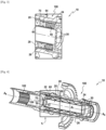
Fig. 2 ] Lafigure 2 est une vue en perspective latérale du système de lafigure 1 , représentant un arbre d'entraînement du système en coupe, un insert du système en coupe partielle, un piston du système en coupe et un élément de sollicitation du système en coupe dans un état comprimé ; - [
Fig. 3 ] Lafigure 3 est une vue partielle agrandie prise sur lafigure 2 , en insistant sur le piston et l'élément de sollicitation du système ; - [
Fig. 4 ] Lafigure 4 est une vue en perspective latérale du système de lafigure 1 , représentant l'arbre d'entraînement du système en coupe, l'insert du système en coupe partielle, le piston du système en coupe et l'élément de sollicitation du système en coupe dans un état étendu ; - [
Fig. 5 ] Lafigure 5 est une vue agrandie prise sur lafigure 4 , en insistant sur le piston et l'élément de sollicitation du système ; - [
Fig. 6 ] Lafigure 6 est une vue en perspective latérale du système selon les aspects de l'invention, représentant l'arbre d'entraînement du système en coupe, l'insert du système en coupe partielle, le piston du système en coupe et l'élément de sollicitation du système en coupe à l'état étendu ; - [
Fig. 7 ] Lafigure 7 est une vue partielle agrandie prise sur lafigure 6 , en insistant sur le piston et l'élément de sollicitation du système ; - [
Fig. 8 ] Lafigure 8 est une vue en perspective latérale du système selon lafigure 6 , représentant l'arbre d'entraînement du système en coupe, l'insert du système en coupe partielle, le piston du système en coupe, et l'élément de sollicitation du système en coupe à l'état comprimé ; - [
Fig. 9 ] Lafigure 9 est une vue partielle agrandie prise sur lafigure 8 , en insistant sur le piston et l'élément de sollicitation du système ; - [
Fig. 10A ] Lafigure 10A est une vue en coupe de face de l'insert du système de lafigure 1 pendant un état de repos selon les aspects de l'invention ; et - [
Fig. 10B ] Lafigure 10B est une vue en coupe de face de l'insert du système de lafigure 1 pendant un état de rotation selon les aspects de l'invention.
- [
Fig. 1 ] Therefigure 1 is a side sectional view of a lubrication system for use in a relay box (hereinafter "the system") according to aspects of the invention; - [
Fig. 2 ] Therefigure 2 is a side perspective view of the system of thefigure 1 , representing a cross-sectional system drive shaft, a partial cross-sectional system insert, a cross-sectional system piston and a cross-sectional system biasing member in a compressed state; - [
Fig. 3 ] ThereFigure 3 is an enlarged partial view taken on thefigure 2 , with emphasis on the piston and the biasing element of the system; - [
Fig. 4 ] Therefigure 4 is a side perspective view of the system of thefigure 1 , showing the cross-sectional system drive shaft, the partial cross-sectional system insert, the cross-sectional system piston and the cross-sectional system biasing member in an extended state; - [
Fig. 5 ] Therefigure 5 is an enlarged view taken on thefigure 4 , with emphasis on the piston and the biasing element of the system; - [
Fig. 6 ] ThereFigure 6 is a side perspective view of the system according to aspects of the invention, showing the drive shaft of the system in section, the insert of the system in partial section, the piston of the system in section and the biasing element of the cross-sectional system in the extended state; - [
Fig. 7 ] ThereFigure 7 is an enlarged partial view taken on theFigure 6 , with emphasis on the piston and the biasing element of the system; - [
Fig. 8 ] Therefigure 8 is a side perspective view of the system according toFigure 6 , representing the drive shaft of the system in section, the insert of the system in partial section, the piston of the system in section, and the biasing element of the system in section in the compressed state; - [
Fig. 9 ] ThereFigure 9 is an enlarged partial view taken on thefigure 8 , with emphasis on the piston and the biasing element of the system; - [
Fig. 10A ] ThereFigure 10A is a front sectional view of the insert of the system of thefigure 1 during a resting state according to aspects of the invention; And - [
Fig. 10B ] ThereFigure 10B is a front sectional view of the insert of the system of thefigure 1 during a rotating state according to aspects of the invention.
Un mode de réalisation d'un système de lubrification (ci-après « le système ») destiné à être utilisé dans un boîtier de relais selon les aspects de l'invention est décrit maintenant en référence aux
Le terme « exemplaire » est utilisé dans le sens « d'exemple » plutôt que « idéal ». Alors que les aspects de l'invention sont favorables à différentes modifications et formes en variante, leurs spécificités ont été présentées à titre d'exemple dans les dessins et seront décrites de manière détaillée. Il faut cependant comprendre que l'intention n'est pas de limiter les aspects de l'invention au(x) mode(s) de réalisation particulier(s) décrit(s). Au contraire, l'intention de la présente invention est de couvrir toutes les modifications, tous les équivalents et les variantes se trouvant dans la portée de l'invention, telle que définie par les revendications.The term “exemplary” is used in the sense of “example” rather than “ideal”. While aspects of the invention are amenable to various modifications and alternative forms, their specifics have been presented by way of example in the drawings and will be described in detail. It should be understood, however, that the intention is not to limit aspects of the invention to the particular embodiment(s) described. Rather, it is the intent of the present invention to cover all modifications, equivalents and variations within the scope of the invention as defined by the claims.
Différents matériaux, procédés de construction et procédés de fixation seront abordés dans le contexte du (des) mode(s) de réalisation décrit(s). L'homme du métier reconnaîtra des substituts connus pour les matériaux, les procédés de construction et les procédés de fixation, dont tous sont envisagés comme étant compatibles avec le(s) mode(s) de réalisation décrit(s) et sont prévus pour être englobés par les revendications jointes.Different materials, construction processes and fixing processes will be discussed in the context of the described embodiment(s). Those skilled in the art will recognize known substitutes for materials, construction methods and fastening methods, all of which are contemplated to be compatible with the described embodiment(s) and are intended to be covered by the appended claims.
Lorsqu'un élément ou caractéristique est désigné(e) ici comme étant « sur », « mis(e) en prise avec », « raccordé(e) à » ou « couplé(e) à » un autre élément ou caractéristique, il (elle) peut être directement sur, mis(e) en prise, raccordé(e) ou couplé(e) à un autre élément ou caractéristique, ou des éléments ou caractéristiques intermédiaires peuvent être présents (présentes). En contraste, lorsqu'un élément ou caractéristique est désigné(e) comme étant « directement sur », « directement mis(e) en prise avec », « directement raccordé(e) à » ou « directement couplé(e) à » un autre élément ou caractéristique, il peut ne pas y avoir d'éléments ou caractéristiques intermédiaires. D'autres termes utilisés pour décrire la relation entre des éléments ou des caractéristiques doivent être interprétés d'une manière identique (par exemple, « entre » opposé à « directement entre », « adjacent » opposé à « directement adjacent », etc.).When an element or feature is referred to herein as being "on", "engaged with", "connected to" or "coupled to" another element or feature, it (it) may be directly on, engaged, connected or coupled to another element or feature, or intermediate elements or features may be present. In contrast, when an element or feature is referred to as being "directly on", "directly engaged with", "directly connected to" or "directly coupled to" a other element or characteristic, there may be no intermediate elements or characteristics. Other terms used to describe the relationship between elements or features should be interpreted in an identical manner (e.g., “between” versus “directly between,” “adjacent” versus “directly adjacent,” etc.) .
Les termes relatifs à l'espace, tels que « haut », « bas », « central », « interne », « externe », « au-dessous », « dessous », « inférieur », « au-dessus », « supérieur », et similaires peuvent être utilisés ici par souci de faciliter la description pour décrire la relation d'un élément ou d'une caractéristique par rapport à un(e) autre (d'autres) élément(s) ou caractéristique(s), comme illustré sur les dessins. Les termes relatifs à l'espace peuvent être prévus pour englober différentes orientations d'un dispositif à l'usage ou en fonctionnement en plus de l'orientation illustrée sur les dessins. Par exemple, si le dispositif sur les dessins est retourné, les éléments décrits comme étant « dessous » ou « au-dessous » des autres éléments ou caractéristiques, sont alors orientés « au-dessus » des autres éléments ou caractéristiques. Ainsi, le terme exemplaire « dessous » peut englober à la fois l'orientation de dessus et de dessous. Le dispositif peut être sinon orienté (entraîné en rotation à 90 degrés ou à d'autres orientations) et les descriptifs relatifs à l'espace utilisés ici, interprétés en conséquence.Terms relating to space, such as "top", "bottom", "central", "internal", "external", "below", "below", "lower", "above", “superior”, and the like may be used here for ease of description to describe the relationship of an element or characteristic to another element(s) or characteristic(s), as illustrated in the drawings. Space-related terms may be intended to encompass different orientations of a device to use or operation in addition to the orientation shown on the drawings. For example, if the device in the drawings is turned upside down, the elements described as being "below" or "beneath" the other elements or features, are then oriented "above" the other elements or features. Thus, the exemplary term “underneath” can encompass both the above and below orientation. The device may otherwise be oriented (rotated 90 degrees or other orientations) and the spatial descriptions used herein interpreted accordingly.
Bien que les termes « premier », « second », etc. peuvent être utilisés ici pour décrire différents éléments, composants, régions, couches, sections et/ou paramètres, ces éléments, composants, régions, couches, sections et/ou paramètres ne doivent pas être limités par ces termes. Ces termes sont uniquement utilisés pour distinguer un élément, composant, région, couche ou section d'une autre région, couche ou section. Ainsi, un premier élément, composant, région, couche ou section abordé(e) ici peut être qualifié(e) de second élément, composant, région, couche ou section sans pour autant s'éloigner des enseignements de la présente invention.Although the terms “first”, “second”, etc. may be used herein to describe different elements, components, regions, layers, sections and/or parameters, such elements, components, regions, layers, sections and/or parameters shall not be limited by these terms. These terms are only used to distinguish an element, component, region, layer or section from another region, layer or section. Thus, a first element, component, region, layer or section discussed here may be qualified as a second element, component, region, layer or section without departing from the teachings of the present invention.
Comme représenté sur les
Comme représenté sur la
Comme représenté sur la
En référence à la
Comme représenté sur la
Comme représenté sur les
Comme représenté sur les
Le fluide 15 est amené à l'insert 15 par la buse 50 pendant la rotation de l'arbre d'entraînement 100 et donc la rotation de l'insert 20. Comme illustré par la
Comme représenté sur les
Comme abordé ci-dessus, le fluide 15 est amené à l'insert 15 par la buse 50 pendant la rotation de l'arbre d'entraînement 100 et donc la rotation de l'insert 20. La rotation de l'arbre d'entraînement 100 et donc la rotation de l'insert 20, génère le volume de rotation du fluide 15, qui exerce la force centrifuge dans la chambre 28 de l'insert 20. La force centrifuge du volume de rotation du fluide 15 augmente la pression dans la chambre 28. La pression accrue dans la chambre 28 augmente la pression exercée sur la surface 70 du piston 60 dans la chambre 28. De plus ou en variante, on envisage que l'augmentation du fluide 15 dans la chambre 28 provoque une augmentation de la pression de fluide exercée sur la surface 70 du piston 60. Comme représenté sur les
Comme représenté sur les
Le positionnement de l'insert 20 dans l'arbre d'entraînement 100 est configuré pour être maintenu pendant l'état de rotation et l'état de repos. Comme représenté sur la
En fonctionnement, l'arbre d'entraînement 100 effectue une transition de l'état de repos à l'état de rotation. L'insert 20 est configuré pour être alimenté avec le fluide 15 par la buse 50 pendant l'état de rotation et pour amener le fluide aux cannelures 102 par le biais de la buse 50 pendant l'état de repos. Pendant la rotation, le fluide 15 est amené de la conduite d'alimentation à l'insert 20. Le fluide 15 pénètre dans l'insert 20 par la première ouverture 54 de la buse 50, se déplace par le conduit 52 et pénètre dans la chambre 28 par la seconde ouverture 56 de la buse. Pendant la rotation de l'arbre d'entraînement 100, le fluide 15 forme le volume de rotation dans l'insert 20 et génère la force centrifuge. La force centrifuge augmente la pression dans la chambre 28 de l'insert 20 qui agit sur la surface 70 du piston 60 pour déplacer le piston 60 de la première position à la seconde position. Lorsque le fluide 15 pénètre dans la chambre 28, le déplacement du piston 60 vers la seconde position étend ou comprime l'élément de sollicitation 66. L'extension ou la compression de l'élément de sollicitation 66 crée une force de rappel, qui est exploitée pour décharger un jet dirigé de fluide 15 par la buse 50 suite à l'achèvement du cycle de fonctionnement.In operation, the
A l'achèvement du cycle de fonctionnement, l'arbre d'entraînement 100 effectue une transition de l'état de rotation à l'état de repos. Pendant l'arrêt de la rotation de l'arbre d'entraînement 100 et/ou lorsque la rotation de l'arbre d'entraînement 100 s'arrête, le fluide 15 n'est plus fourni à la chambre 28 de l'insert 20. De plus, pendant l'arrêt de la rotation de l'arbre d'entraînement 100 et/ou lorsque la rotation de l'arbre d'entraînement 100 s'arrête, le volume de rotation du fluide 15 s'établit dans le volume de fluide affaissé 15. L'arrêt de la rotation de l'insert 20 diminue la pression centrifuge du volume de fluide 15 dans la chambre 28 de l'insert 20. La décharge de pression dans la chambre 28 de l'insert 20 amène l'élément de sollicitation 66 à s'étendre ou se comprimer pour déplacer le piston 60 de la seconde position à la première position. Le déplacement du piston 60 de la seconde position à la première position force un jet de fluide 15 hors de la buse 50 vers les cannelures 102. Le jet de fluide 15 peut se déplacer sur de plus longues distances, avec un moment plus élevé, sans dissipation - en contraste au fluide affaissé 15 illustré sur la
Bien que la présente invention a été décrite ici en référence aux modes de réalisation particuliers, il faut comprendre que ces modes de réalisation ne sont qu'illustratifs des principes et des applications de la présente invention.Although the present invention has been described herein with reference to particular embodiments, it should be understood that these embodiments are only illustrative of the principles and applications of the present invention.
Il est prévu que la spécification et les exemples soient considérés comme exemplaires uniquement, avec la véritable portée de l'invention qui est indiquée par les revendications suivantes.It is intended that the specification and examples be considered exemplary only, with the true scope of the invention being indicated by the following claims.
De plus, toutes les caractéristiques décrites d'un appareil peuvent être transposées, seules ou en combinaison, à un procédé et vice versa.Furthermore, all the described characteristics of a device can be transposed, alone or in combination, to a process and vice versa.
Claims (15)
- An insert (20) for supplying a fluid (15) to splines (102) of a drive shaft (10), the insert (20)comprising:an insert wall (26) extending between a first end (22) and a second end (24) of the insert and comprising an outer surface;a chamber (28) surrounding the insert wall (26) for storing a fluid (15), the chamber (28) being defined between the outer surface of the insert wall (26) and the drive shaft (100);a piston (60) having a surface (70) configured to be exposed to the fluid (15), the piston (60) configured to move between a first position and a second position within the chamber (28), and the piston (60) biased toward the first position by a bias member (66); andwherein, an increase in supply of the fluid (15) in the chamber (28) causes the piston (60) to move toward the second position and a decrease in supply of the fluid (15) in the chamber (28) causes the piston (60) to move toward the first position.
- The insert (20) according to claim 1, wherein the insert (10) is configured to rotate around an axis of rotation (AR).
- The insert (20) according to claim 2, wherein the piston (60) moves axially along the outer surface of the insert wall (26).
- The insert (20) according to any of claims 1 to 3, wherein increase in supply of the fluid (15) in the chamber (28) causes pressure to be exerted on the surface (70) of the piston (60).
- The insert (20) according to any of claims 1 to 4, wherein movement of the piston (60) toward the first position forces the fluid (15) out of the chamber (28).
- The insert (20) according to any of claims 1 to 5, wherein the bias member (66) is positioned between the insert wall (26) and the piston (60), and the bias member is configured to transition between an extended state and a compressed state.
- The insert (20) according to any of claims 1 to 6, wherein the surface (70) is annular.
- The insert according to any of claims 1 to 7, wherein the piston (60) is configured to seal against the insert wall (26).
- The insert (20) according to any of claims 1 to 8, wherein the insert includes a nozzle (50) configured to discharge a jet of the fluid (15).
- A system (10) for supplying a fluid (15) to splines (102) of a drive shaft (100), the system (10) comprising:a drive shaft (100) including splines (102) and a weir (104) positioned adjacent the splines (102), the drive shaft (100) configured to rotate about an axis of rotation (AR);an insert (20) according to any of claims 1 to 9, the insert wall (26) extending concentrically with the drive shaft (100); andwherein, an increase in pressure in the chamber (28) during rotation of the drive shaft (100) causes the piston (60) to move toward the second position and a decrease in pressure in the chamber during cessation of rotation of the drive shaft (100) causes the piston (60) to move toward the first position.
- The system (10) according to claim 10, wherein the insert (20) is in communication with the weir (104) and the splines (102) at an interface (106) within the drive shaft (100).
- The system (10) according to claim 11, wherein the insert (20) is according to claim 9 and the nozzle (50) is configured to target the jet of the fluid (15) toward the axis of rotation (AR) and through the interface (106) and past the weir (104) to the splines (102) when rotation of the drive shaft (100) is ceased.
- The system (10) according to any of claims 10 to 12, wherein the insert (20) is secured to the drive shaft (100) to maintain position and anti-rotation of the insert (20) within the drive shaft (100).
- The system (10) according to any of claims 10 to 13, wherein the piston (60) is configured to seal against a surface surrounding the insert (20) within the drive shaft (100).
- The system (10) according to any of claims 10 to 14, wherein the insert (20) has an outside diameter (DO1) which is less than an inside diameter (di1) of the drive shaft (100) so that the chamber (28) is defined between the insert (20) and a surface surrounding the insert (20) within the drive shaft (100).
Applications Claiming Priority (1)
| Application Number | Priority Date | Filing Date | Title |
|---|---|---|---|
| FR2006051A FR3111380B1 (en) | 2020-06-10 | 2020-06-10 | Lubrication system for supplying fluid to the splines of a drive shaft |
Publications (2)
| Publication Number | Publication Date |
|---|---|
| EP3922816A1 EP3922816A1 (en) | 2021-12-15 |
| EP3922816B1 true EP3922816B1 (en) | 2024-02-14 |
Family
ID=73013526
Family Applications (1)
| Application Number | Title | Priority Date | Filing Date |
|---|---|---|---|
| EP21305766.4A Active EP3922816B1 (en) | 2020-06-10 | 2021-06-07 | Lubrication system for supplying a fluid to the splines of a drive shaft |
Country Status (3)
| Country | Link |
|---|---|
| US (1) | US11879539B2 (en) |
| EP (1) | EP3922816B1 (en) |
| FR (1) | FR3111380B1 (en) |
Families Citing this family (1)
| Publication number | Priority date | Publication date | Assignee | Title |
|---|---|---|---|---|
| FR3111378B1 (en) * | 2020-06-10 | 2022-06-24 | Aero Gearbox Int | Lubrication system for supplying fluid to the splines of a drive shaft |
Family Cites Families (7)
| Publication number | Priority date | Publication date | Assignee | Title |
|---|---|---|---|---|
| GB1248437A (en) * | 1968-10-24 | 1971-10-06 | Rolls Royce | Lubrication system |
| US3847248A (en) * | 1973-08-23 | 1974-11-12 | Caterpillar Tractor Co | Replaceable lubricating cartridge for spline connections |
| US3990538A (en) * | 1975-01-06 | 1976-11-09 | Caterpillar Tractor Co. | Capsule lubricator |
| US4567784A (en) * | 1983-03-31 | 1986-02-04 | Dresser Industries, Inc. | Method and apparatus for lubricating a transmission |
| US5119905A (en) * | 1991-10-28 | 1992-06-09 | General Motors Corporation | Accessory drive spline lubrication system for a turbine engine reduction gear box |
| US8678937B2 (en) * | 2009-12-01 | 2014-03-25 | Rolls-Royce Corporation | Shaft coupling |
| FR2977280B1 (en) | 2011-06-28 | 2015-04-10 | Hispano Suiza Sa | IMPROVED RELAY HOUSING FOR ACCESSORIES OF A GAS TURBINE |
-
2020
- 2020-06-10 FR FR2006051A patent/FR3111380B1/en active Active
-
2021
- 2021-06-07 EP EP21305766.4A patent/EP3922816B1/en active Active
- 2021-06-09 US US17/343,450 patent/US11879539B2/en active Active
Also Published As
| Publication number | Publication date |
|---|---|
| EP3922816A1 (en) | 2021-12-15 |
| US20210388896A1 (en) | 2021-12-16 |
| FR3111380B1 (en) | 2022-06-24 |
| FR3111380A1 (en) | 2021-12-17 |
| US11879539B2 (en) | 2024-01-23 |
Similar Documents
| Publication | Publication Date | Title |
|---|---|---|
| EP0231673B1 (en) | Composite sealing arrangement | |
| FR2799246A1 (en) | MULTIPLE CLUTCH INSTALLATION WITH AT LEAST ONE BEARING DEVICE | |
| FR2799250A1 (en) | MULTIPLE CLUTCH INSTALLATION WITH AT LEAST ONE PACKAGE OF LAMELLES PARTLY WITHOUT FRICTION TRIM | |
| EP3247924B1 (en) | Integration of a pump on a pinion shank | |
| FR2799247A1 (en) | MULTIPLE CLUTCH SYSTEM WITH A CENTRIFUGAL FORCE PRESSURE COMPENSATION CHAMBER | |
| FR2689591A1 (en) | Transmission with winding member. | |
| FR2811726A1 (en) | Multiple clutch for motor vehicle transmission has pair of clutches driving respective outputs and with vibration damper | |
| FR2908844A1 (en) | VARIABLE DISPLACEMENT PALLET PUMP | |
| EP3922816B1 (en) | Lubrication system for supplying a fluid to the splines of a drive shaft | |
| FR2834016A1 (en) | Jet pump for transferring fuel between different compartments in multi-compartment fuel tanks, has sealing elements each adapted to open when pressure of injected fluid exceeds predetermined level | |
| EP3922815B1 (en) | Lubrication system for supplying a fluid to the splines of a drive shaft | |
| EP0663545A1 (en) | Hydraulic tensioner for an endless member, particularly for a drive chain of an internal combustion engine | |
| FR2608224A1 (en) | AXIAL PISTON PUMP | |
| FR2785356A1 (en) | Control valve with a piston having a area for the passage of hydraulic fluid in rotation reduces hysteresis effects | |
| EP3922814B1 (en) | Lubrication system for supplying a fluid to the splines of a drive shaft | |
| EP0484209B1 (en) | Retractable axial bearing with flexible membrane for a rotary machine | |
| EP3234396B1 (en) | Motor vehicle clutch device | |
| FR3075901A1 (en) | TORQUE TRANSMISSION MODULE FOR EQUIPPING A TRANSMISSION OF A MOTOR VEHICLE | |
| WO2002014705A1 (en) | Device for coupling a lever to a shift cylinder piston | |
| WO2017220735A1 (en) | Hydrokinetic clutch for a motor vehicle | |
| EP3199244A1 (en) | Suction device for liquid product in a dispenser | |
| WO2001081792A1 (en) | Hydrokinetic coupling apparatus in particular for motor vehicle | |
| FR2649449A1 (en) | Vane-type vacuum pump for boost systems in motor vehicles. | |
| FR2973452A1 (en) | INTERNAL GEAR PUMP | |
| FR2812364A1 (en) | Hydraulic tensioner for endless link comprises cylindrical housing containing hollow piston, spring which, with piston and housing supports and non-return valve, constitute sub-assembly introduced into high pressure chamber |
Legal Events
| Date | Code | Title | Description |
|---|---|---|---|
| PUAI | Public reference made under article 153(3) epc to a published international application that has entered the european phase |
Free format text: ORIGINAL CODE: 0009012 |
|
| STAA | Information on the status of an ep patent application or granted ep patent |
Free format text: STATUS: REQUEST FOR EXAMINATION WAS MADE |
|
| 17P | Request for examination filed |
Effective date: 20210607 |
|
| AK | Designated contracting states |
Kind code of ref document: A1 Designated state(s): AL AT BE BG CH CY CZ DE DK EE ES FI FR GB GR HR HU IE IS IT LI LT LU LV MC MK MT NL NO PL PT RO RS SE SI SK SM TR |
|
| B565 | Issuance of search results under rule 164(2) epc |
Effective date: 20210820 |
|
| GRAP | Despatch of communication of intention to grant a patent |
Free format text: ORIGINAL CODE: EPIDOSNIGR1 |
|
| STAA | Information on the status of an ep patent application or granted ep patent |
Free format text: STATUS: GRANT OF PATENT IS INTENDED |
|
| INTG | Intention to grant announced |
Effective date: 20230920 |
|
| GRAS | Grant fee paid |
Free format text: ORIGINAL CODE: EPIDOSNIGR3 |
|
| GRAA | (expected) grant |
Free format text: ORIGINAL CODE: 0009210 |
|
| STAA | Information on the status of an ep patent application or granted ep patent |
Free format text: STATUS: THE PATENT HAS BEEN GRANTED |
|
| AK | Designated contracting states |
Kind code of ref document: B1 Designated state(s): AL AT BE BG CH CY CZ DE DK EE ES FI FR GB GR HR HU IE IS IT LI LT LU LV MC MK MT NL NO PL PT RO RS SE SI SK SM TR |
|
| REG | Reference to a national code |
Ref country code: GB Ref legal event code: FG4D Free format text: NOT ENGLISH |
|
| REG | Reference to a national code |
Ref country code: CH Ref legal event code: EP |
|
| REG | Reference to a national code |
Ref country code: DE Ref legal event code: R096 Ref document number: 602021009377 Country of ref document: DE |
|
| REG | Reference to a national code |
Ref country code: IE Ref legal event code: FG4D Free format text: LANGUAGE OF EP DOCUMENT: FRENCH |