EP3922480B1 - Emblem for vehicles - Google Patents
Emblem for vehicles Download PDFInfo
- Publication number
- EP3922480B1 EP3922480B1 EP21176875.9A EP21176875A EP3922480B1 EP 3922480 B1 EP3922480 B1 EP 3922480B1 EP 21176875 A EP21176875 A EP 21176875A EP 3922480 B1 EP3922480 B1 EP 3922480B1
- Authority
- EP
- European Patent Office
- Prior art keywords
- emblem
- printed circuit
- circuit board
- vehicles according
- windings
- Prior art date
- Legal status (The legal status is an assumption and is not a legal conclusion. Google has not performed a legal analysis and makes no representation as to the accuracy of the status listed.)
- Active
Links
Images


Classifications
-
- B—PERFORMING OPERATIONS; TRANSPORTING
- B60—VEHICLES IN GENERAL
- B60R—VEHICLES, VEHICLE FITTINGS, OR VEHICLE PARTS, NOT OTHERWISE PROVIDED FOR
- B60R13/00—Elements for body-finishing, identifying, or decorating; Arrangements or adaptations for advertising purposes
- B60R13/005—Manufacturers' emblems, name plates, bonnet ornaments, mascots or the like; Mounting means therefor
-
- B—PERFORMING OPERATIONS; TRANSPORTING
- B60—VEHICLES IN GENERAL
- B60B—VEHICLE WHEELS; CASTORS; AXLES FOR WHEELS OR CASTORS; INCREASING WHEEL ADHESION
- B60B7/00—Wheel cover discs, rings, or the like, for ornamenting, protecting, venting, or obscuring, wholly or in part, the wheel body, rim, hub, or tyre sidewall, e.g. wheel cover discs, wheel cover discs with cooling fins
- B60B7/0026—Wheel cover discs, rings, or the like, for ornamenting, protecting, venting, or obscuring, wholly or in part, the wheel body, rim, hub, or tyre sidewall, e.g. wheel cover discs, wheel cover discs with cooling fins characterised by the surface
- B60B7/0033—Wheel cover discs, rings, or the like, for ornamenting, protecting, venting, or obscuring, wholly or in part, the wheel body, rim, hub, or tyre sidewall, e.g. wheel cover discs, wheel cover discs with cooling fins characterised by the surface the dominant aspect being the surface appearance
- B60B7/006—Wheel cover discs, rings, or the like, for ornamenting, protecting, venting, or obscuring, wholly or in part, the wheel body, rim, hub, or tyre sidewall, e.g. wheel cover discs, wheel cover discs with cooling fins characterised by the surface the dominant aspect being the surface appearance the surface being reflective or including lighting
-
- B—PERFORMING OPERATIONS; TRANSPORTING
- B60—VEHICLES IN GENERAL
- B60B—VEHICLE WHEELS; CASTORS; AXLES FOR WHEELS OR CASTORS; INCREASING WHEEL ADHESION
- B60B7/00—Wheel cover discs, rings, or the like, for ornamenting, protecting, venting, or obscuring, wholly or in part, the wheel body, rim, hub, or tyre sidewall, e.g. wheel cover discs, wheel cover discs with cooling fins
- B60B7/0013—Hub caps
-
- B—PERFORMING OPERATIONS; TRANSPORTING
- B60—VEHICLES IN GENERAL
- B60B—VEHICLE WHEELS; CASTORS; AXLES FOR WHEELS OR CASTORS; INCREASING WHEEL ADHESION
- B60B7/00—Wheel cover discs, rings, or the like, for ornamenting, protecting, venting, or obscuring, wholly or in part, the wheel body, rim, hub, or tyre sidewall, e.g. wheel cover discs, wheel cover discs with cooling fins
- B60B7/0026—Wheel cover discs, rings, or the like, for ornamenting, protecting, venting, or obscuring, wholly or in part, the wheel body, rim, hub, or tyre sidewall, e.g. wheel cover discs, wheel cover discs with cooling fins characterised by the surface
- B60B7/0033—Wheel cover discs, rings, or the like, for ornamenting, protecting, venting, or obscuring, wholly or in part, the wheel body, rim, hub, or tyre sidewall, e.g. wheel cover discs, wheel cover discs with cooling fins characterised by the surface the dominant aspect being the surface appearance
- B60B7/0053—Wheel cover discs, rings, or the like, for ornamenting, protecting, venting, or obscuring, wholly or in part, the wheel body, rim, hub, or tyre sidewall, e.g. wheel cover discs, wheel cover discs with cooling fins characterised by the surface the dominant aspect being the surface appearance the surface being decorated
-
- B—PERFORMING OPERATIONS; TRANSPORTING
- B60—VEHICLES IN GENERAL
- B60B—VEHICLE WHEELS; CASTORS; AXLES FOR WHEELS OR CASTORS; INCREASING WHEEL ADHESION
- B60B7/00—Wheel cover discs, rings, or the like, for ornamenting, protecting, venting, or obscuring, wholly or in part, the wheel body, rim, hub, or tyre sidewall, e.g. wheel cover discs, wheel cover discs with cooling fins
- B60B7/06—Fastening arrangements therefor
-
- B—PERFORMING OPERATIONS; TRANSPORTING
- B60—VEHICLES IN GENERAL
- B60B—VEHICLE WHEELS; CASTORS; AXLES FOR WHEELS OR CASTORS; INCREASING WHEEL ADHESION
- B60B7/00—Wheel cover discs, rings, or the like, for ornamenting, protecting, venting, or obscuring, wholly or in part, the wheel body, rim, hub, or tyre sidewall, e.g. wheel cover discs, wheel cover discs with cooling fins
- B60B7/20—Wheel cover discs, rings, or the like, for ornamenting, protecting, venting, or obscuring, wholly or in part, the wheel body, rim, hub, or tyre sidewall, e.g. wheel cover discs, wheel cover discs with cooling fins having an element mounted for rotation independently of wheel rotation
-
- B—PERFORMING OPERATIONS; TRANSPORTING
- B60—VEHICLES IN GENERAL
- B60Q—ARRANGEMENT OF SIGNALLING OR LIGHTING DEVICES, THE MOUNTING OR SUPPORTING THEREOF OR CIRCUITS THEREFOR, FOR VEHICLES IN GENERAL
- B60Q1/00—Arrangement of optical signalling or lighting devices, the mounting or supporting thereof or circuits therefor
- B60Q1/26—Arrangement of optical signalling or lighting devices, the mounting or supporting thereof or circuits therefor the devices being primarily intended to indicate the vehicle, or parts thereof, or to give signals, to other traffic
- B60Q1/32—Arrangement of optical signalling or lighting devices, the mounting or supporting thereof or circuits therefor the devices being primarily intended to indicate the vehicle, or parts thereof, or to give signals, to other traffic for indicating vehicle sides, e.g. clearance lights
- B60Q1/326—Arrangement of optical signalling or lighting devices, the mounting or supporting thereof or circuits therefor the devices being primarily intended to indicate the vehicle, or parts thereof, or to give signals, to other traffic for indicating vehicle sides, e.g. clearance lights on or for wheels
-
- F—MECHANICAL ENGINEERING; LIGHTING; HEATING; WEAPONS; BLASTING
- F21—LIGHTING
- F21V—FUNCTIONAL FEATURES OR DETAILS OF LIGHTING DEVICES OR SYSTEMS THEREOF; STRUCTURAL COMBINATIONS OF LIGHTING DEVICES WITH OTHER ARTICLES, NOT OTHERWISE PROVIDED FOR
- F21V21/00—Supporting, suspending, or attaching arrangements for lighting devices; Hand grips
- F21V21/08—Devices for easy attachment to any desired place, e.g. clip, clamp, magnet
- F21V21/096—Magnetic devices
-
- H—ELECTRICITY
- H02—GENERATION; CONVERSION OR DISTRIBUTION OF ELECTRIC POWER
- H02K—DYNAMO-ELECTRIC MACHINES
- H02K1/00—Details of the magnetic circuit
- H02K1/06—Details of the magnetic circuit characterised by the shape, form or construction
- H02K1/12—Stationary parts of the magnetic circuit
-
- H—ELECTRICITY
- H02—GENERATION; CONVERSION OR DISTRIBUTION OF ELECTRIC POWER
- H02K—DYNAMO-ELECTRIC MACHINES
- H02K1/00—Details of the magnetic circuit
- H02K1/06—Details of the magnetic circuit characterised by the shape, form or construction
- H02K1/22—Rotating parts of the magnetic circuit
- H02K1/27—Rotor cores with permanent magnets
-
- H—ELECTRICITY
- H05—ELECTRIC TECHNIQUES NOT OTHERWISE PROVIDED FOR
- H05K—PRINTED CIRCUITS; CASINGS OR CONSTRUCTIONAL DETAILS OF ELECTRIC APPARATUS; MANUFACTURE OF ASSEMBLAGES OF ELECTRICAL COMPONENTS
- H05K1/00—Printed circuits
- H05K1/18—Printed circuits structurally associated with non-printed electric components
- H05K1/181—Printed circuits structurally associated with non-printed electric components associated with surface mounted components
-
- H—ELECTRICITY
- H05—ELECTRIC TECHNIQUES NOT OTHERWISE PROVIDED FOR
- H05K—PRINTED CIRCUITS; CASINGS OR CONSTRUCTIONAL DETAILS OF ELECTRIC APPARATUS; MANUFACTURE OF ASSEMBLAGES OF ELECTRICAL COMPONENTS
- H05K5/00—Casings, cabinets or drawers for electric apparatus
- H05K5/02—Details
- H05K5/03—Covers
-
- H—ELECTRICITY
- H05—ELECTRIC TECHNIQUES NOT OTHERWISE PROVIDED FOR
- H05K—PRINTED CIRCUITS; CASINGS OR CONSTRUCTIONAL DETAILS OF ELECTRIC APPARATUS; MANUFACTURE OF ASSEMBLAGES OF ELECTRICAL COMPONENTS
- H05K7/00—Constructional details common to different types of electric apparatus
- H05K7/14—Mounting supporting structure in casing or on frame or rack
- H05K7/1422—Printed circuit boards receptacles, e.g. stacked structures, electronic circuit modules or box like frames
- H05K7/1427—Housings
-
- B—PERFORMING OPERATIONS; TRANSPORTING
- B60—VEHICLES IN GENERAL
- B60B—VEHICLE WHEELS; CASTORS; AXLES FOR WHEELS OR CASTORS; INCREASING WHEEL ADHESION
- B60B2310/00—Manufacturing methods
- B60B2310/60—Surface treatment; After treatment
- B60B2310/64—Effect of treatments
- B60B2310/656—Decorative
-
- B—PERFORMING OPERATIONS; TRANSPORTING
- B60—VEHICLES IN GENERAL
- B60B—VEHICLE WHEELS; CASTORS; AXLES FOR WHEELS OR CASTORS; INCREASING WHEEL ADHESION
- B60B2320/00—Manufacturing or maintenance operations
- B60B2320/10—Assembling; disassembling
- B60B2320/16—Devices for attaching or removing cover discs, hub caps or other ornamental rings or elements
-
- B—PERFORMING OPERATIONS; TRANSPORTING
- B60—VEHICLES IN GENERAL
- B60B—VEHICLE WHEELS; CASTORS; AXLES FOR WHEELS OR CASTORS; INCREASING WHEEL ADHESION
- B60B2900/00—Purpose of invention
- B60B2900/50—Improvement of
- B60B2900/572—Visual appearance
-
- B—PERFORMING OPERATIONS; TRANSPORTING
- B60—VEHICLES IN GENERAL
- B60B—VEHICLE WHEELS; CASTORS; AXLES FOR WHEELS OR CASTORS; INCREASING WHEEL ADHESION
- B60B7/00—Wheel cover discs, rings, or the like, for ornamenting, protecting, venting, or obscuring, wholly or in part, the wheel body, rim, hub, or tyre sidewall, e.g. wheel cover discs, wheel cover discs with cooling fins
- B60B7/04—Wheel cover discs, rings, or the like, for ornamenting, protecting, venting, or obscuring, wholly or in part, the wheel body, rim, hub, or tyre sidewall, e.g. wheel cover discs, wheel cover discs with cooling fins built-up of several main parts
-
- B—PERFORMING OPERATIONS; TRANSPORTING
- B60—VEHICLES IN GENERAL
- B60B—VEHICLE WHEELS; CASTORS; AXLES FOR WHEELS OR CASTORS; INCREASING WHEEL ADHESION
- B60B7/00—Wheel cover discs, rings, or the like, for ornamenting, protecting, venting, or obscuring, wholly or in part, the wheel body, rim, hub, or tyre sidewall, e.g. wheel cover discs, wheel cover discs with cooling fins
- B60B7/06—Fastening arrangements therefor
- B60B7/061—Fastening arrangements therefor characterised by the part of the wheels to which the discs, rings or the like are mounted
- B60B7/066—Fastening arrangements therefor characterised by the part of the wheels to which the discs, rings or the like are mounted to the hub
-
- H—ELECTRICITY
- H05—ELECTRIC TECHNIQUES NOT OTHERWISE PROVIDED FOR
- H05K—PRINTED CIRCUITS; CASINGS OR CONSTRUCTIONAL DETAILS OF ELECTRIC APPARATUS; MANUFACTURE OF ASSEMBLAGES OF ELECTRICAL COMPONENTS
- H05K2201/00—Indexing scheme relating to printed circuits covered by H05K1/00
- H05K2201/10—Details of components or other objects attached to or integrated in a printed circuit board
- H05K2201/10007—Types of components
- H05K2201/10083—Electromechanical or electro-acoustic component, e.g. microphone
-
- H—ELECTRICITY
- H05—ELECTRIC TECHNIQUES NOT OTHERWISE PROVIDED FOR
- H05K—PRINTED CIRCUITS; CASINGS OR CONSTRUCTIONAL DETAILS OF ELECTRIC APPARATUS; MANUFACTURE OF ASSEMBLAGES OF ELECTRICAL COMPONENTS
- H05K2201/00—Indexing scheme relating to printed circuits covered by H05K1/00
- H05K2201/10—Details of components or other objects attached to or integrated in a printed circuit board
- H05K2201/10007—Types of components
- H05K2201/10106—Light emitting diode [LED]
Definitions
- the present invention refers to an emblem for vehicles, in particular to an emblem that is used in a fixed orientation on hubs of vehicle wheels.
- US 7168831 B2 discloses a power generation unit and a magnetic core fitted on a fastening shaft that rotates with the wheel. This requires a power supply terminal and an electric line to connect them to the printed circuit board that contains the LEDs.
- the power generation unit (or coil) requires a significant investment and the total solution requires a significant space in the axial direction.
- US 10442242 B2 discloses an electrical energy generating system. It contains magnets on the surface of the member that rotates with the wheel.
- the printed circuit board that is electrically connected to the stator (coil) and to the LEDs, is assembled to a bearing to avoid it rotates with the rotating shaft.
- the coil of the stator requires a significant investment, difficult to be financially justified if the number of devices to be manufactured is low.
- KR20140019045A discloses a wheel cap device capable of sensing and advertising by the rotary power of a wheel. The wheel cap device supplies light to a specific advertisement sentence composed of characters or symbols from a power source supplied by self-generation using the rotary power of the wheel of a vehicle and senses a lane distance and a distance between the vehicles.
- US2005140201A1 discloses a wheel cover for an automobile wheel cover that includes a main body having a plurality of light emitting members, and a generating device mounted in the main body and including a housing, a shaft, a rotor, a counterweight having a sensing body, a coil set, and a circuit board having a sensing body that is movable to align with the sensing body of the counterweight.
- one purpose of the present invention is to provide an emblem in which a power generator is optimized to be compatible in the axial direction with the available space, which is very small behind the front cover.
- the emblem for vehicles according to the present invention is defined in claim 1, and it comprises:
- the windings of the printed circuit board or of each printed circuit board are connected in series.
- the emblem for vehicles according to the present invention also comprises an eccentric weight.
- a spacer is placed between the support disc and the or each printed circuit board, which ensures a controlled distance between the support disc and the printed circuit board in the axial direction.
- the stator comprises two printed circuit boards, the windings of each printed circuit board are connected to each other by pins.
- said at least one printed circuit board comprises magnetic conducting layer and a light guide, wherein the light guide is mounted on the magnetic conducting layer.
- the at least one lighting element is mounted on the at least one printed circuit board.
- the support disc comprises magnets at both sides.
- the emblem for vehicles according to the present invention comprises a housing formed by a base and a cover.
- the available space is very small, and in the emblem according to the present invention the dimensions are optimized to be compatible in the axial direction with the available space.
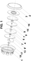
- FIG. 1 and Fig. 2 show the emblem for vehicles according to the present invention.
- a support disc 4 with permanent magnets 5 is fixed on its perimeter to the housing to perform the function of rotor of the electrical power generator when the wheel is rotating.
- the permanent magnets 5 may be with or without alternating polarity.
- the support disc 4 holds a bearing 6 in its axis that allows free rotation of a spacer 7 and a shaft 8.
- the shaft 8 holds a printed circuit board 9 located between the support disc 4 and the cover 2.
- the spacer 7 ensures a controlled distance between the support disc 4 and the printed circuit board 9 in the axial direction.
- the printed circuit board 9 contains one or more layers with sets of windings 10 shown in Fig 3 .
- the different layers of the printed circuit board 9 are connected through vias.
- the layout of the windings 10 may be of conventional design, maintaining the wire trace following the same direction of rotation between layers.
- All windings 10 are connected in series, providing a single output phase.
- This part of the printed circuit board 9 acts as the stator of the electrical power generator.
- the transformation of the generated magnetic field into electrical power may be improved by adding a magnetic conductor layer 11 located on the face of the printed circuit board 9, which is more distant from the permanent magnets 5, confining the magnetic field.
- the generated electrical power may be increased by adding a second printed board 9' hold by the shaft 8 and located close to the face of the support disc 4 which is more distant from the cover 2.
- a spacer 7' ensures a controlled distance between the support disc 4 and the printed circuit board 9' in the axial direction.
- the windings of the printed circuit board 9' have a similar or the same design than the ones of the printed circuit board 9 and are series connected to them through pins 12 located in the inner part of the shaft 8.
- the transformation of the generated magnetic field into electrical power may be improved by adding a magnetic conductor layer 11' located on the face of the printed circuit board 9' which is more distant from the permanent magnets 5, confining the magnetic field.
- the stationary assembly including the spacer 7 (and 7'), the shaft 8 and the printed circuit boards 9 (and 9') also contains a weight 13 eccentrically disposed.
- the gravity force acting on the weight 13 maintains this assembly in a relative constant position despite of the rotating movement of the wheel and, consequently, of the external housing and internal rotor.
- the lighting elements 14 illuminate a light guide 15 located between the printed circuit board 9 and a decoration layer 16.
- the light guide 15 distributes the light, irradiating it through the decoration layer 16.
- the decoration layer 16 may combine opaque and transparent/translucent areas to define a figure (for instance, a manufacturer's emblem) that is desired to highlight with the illumination.
- the light guide 15 and the decoration layer 16 may be two different parts, included on the stationary assembly, fixing them by glue, mechanical interference or soldering. Alternatively, they can be an integrated part, where the decoration layer 16 is just a film on the light guide 15, both included on the stationary assembly. In any case, the decoration layer 16 will also take advantage of the action of the weight 13, remaining at a stationary position, and making the figure more recognizable by an external observer.
- the number of layers of windings 10 to be used on the printed circuit board 9 (and 9') will depend on:
- Fig. 4 shows a graph with the simulation of the illumination power for different number of layers and the vehicle speed. As expected, it may be seen that a larger number of layers allow to achieve the minimum required illumination at a lower speed.
- the printed circuit board 9 connected to the lighting elements 14 may include protection devices to limit the power delivered to the lighting elements 14 when the maximum specified luminosity is achieved, protecting them. These protection devices may take the form of lowpass filters, acting at a vehicle's speed above a specified value. This excess power may charge an energy storage device (a battery or supercapacitor) connected to the printed circuit board.
- an energy storage device a battery or supercapacitor
- the energy available in the energy storage device may feed the lighting elements 14 in periods of time when the vehicle speed is slower than the required to achieve the minimum illumination level specified. If the energy storage device has a significant weight, it will be advisable to locate it eccentrically in the way to help the weight 13 to maintain the assembly at a stationary position thanks to gravity force.
- the front cover may include protective layers (ultraviolet, impact resistance, antireflective) as generally adopted on standard non illuminated wheel hub emblems.
- a back shaft 17 may be included in the stationary assembly, radially positioned respect the base 1 by means of a bearing 18.
Landscapes
- Engineering & Computer Science (AREA)
- Mechanical Engineering (AREA)
- Microelectronics & Electronic Packaging (AREA)
- Power Engineering (AREA)
- General Engineering & Computer Science (AREA)
- Lighting Device Outwards From Vehicle And Optical Signal (AREA)
- Non-Portable Lighting Devices Or Systems Thereof (AREA)
- Vehicle Waterproofing, Decoration, And Sanitation Devices (AREA)
Description
- The present invention refers to an emblem for vehicles, in particular to an emblem that is used in a fixed orientation on hubs of vehicle wheels.
- There is an increasing trend to improve the external appearance of vehicles by adding luminous effects. Additionally, the car manufacturers and the rim manufacturers want to maintain the visibility of their representative emblems in all possible external lighting situations. One possible location to combine both targets is the hub of the automobile wheel by illuminating a figure that remains in stationary condition.
- There is a variety of devices generating electrical energy based on the use of the torque of a wheel. The combination of permanent magnets and coils allows to power the LEDs on a printed circuit board, illuminating an advertisement member.
- This solution has constraints in terms of technical feasibility because of available space and in terms of financial feasibility because of the involved investments and small manufacturing volumes usually associated.
- Some available solutions are described below:
US 7168831 B2 discloses a power generation unit and a magnetic core fitted on a fastening shaft that rotates with the wheel. This requires a power supply terminal and an electric line to connect them to the printed circuit board that contains the LEDs. The power generation unit (or coil) requires a significant investment and the total solution requires a significant space in the axial direction. -
US 10442242 B2 KR20140019045A -
US2005140201A1 discloses a wheel cover for an automobile wheel cover that includes a main body having a plurality of light emitting members, and a generating device mounted in the main body and including a housing, a shaft, a rotor, a counterweight having a sensing body, a coil set, and a circuit board having a sensing body that is movable to align with the sensing body of the counterweight. - Therefore, one purpose of the present invention is to provide an emblem in which a power generator is optimized to be compatible in the axial direction with the available space, which is very small behind the front cover.
- With the emblem for vehicles according to the present invention it is possible to solve said drawbacks, providing other advantages that are described below.
- The emblem for vehicles according to the present invention is defined in
claim 1, and it comprises: - a decoration layer;
- at least one lighting element that illuminates the decoration layer;
- an electrical power generator that feeds electric power to the at least one lighting element, wherein the electrical power generator includes:
- a rotor comprising a support disc for at least one magnet; and
- a stator comprising at least one printed circuit board provided with windings.
- According to a preferred embodiment, the windings of the printed circuit board or of each printed circuit board are connected in series.
- Preferably, for maintaining a fixed position, the emblem for vehicles according to the present invention also comprises an eccentric weight.
- Advantageously, a spacer is placed between the support disc and the or each printed circuit board, which ensures a controlled distance between the support disc and the printed circuit board in the axial direction.
- According to a preferred embodiment, the stator comprises two printed circuit boards, the windings of each printed circuit board are connected to each other by pins.
- Furthermore, said at least one printed circuit board comprises magnetic conducting layer and a light guide, wherein the light guide is mounted on the magnetic conducting layer.
- Preferably, the at least one lighting element is mounted on the at least one printed circuit board.
- According to a preferred embodiment, the support disc comprises magnets at both sides.
- Furthermore, the emblem for vehicles according to the present invention comprises a housing formed by a base and a cover.
- In an emblem for vehicles, the available space is very small, and in the emblem according to the present invention the dimensions are optimized to be compatible in the axial direction with the available space.
- For a better understanding the above explanation and for the sole purpose of providing an example, some non-limiting drawings are included that schematically depict a practical embodiment.
-
Fig. 1 is an exploded view showing the main parts of the emblem for vehicles according to the present invention; -
Fig. 2 is a detailed cross section of the assembled emblem shown onFig. 1 ; -
Fig. 3 is a layer of a printed circuit board showing traces forming windings, used in the emblem for vehicles according to the present invention; and -
Fig. 4 is a simulation of the illumination power depending on the number of layers of a printed circuit board of the emblem according to the present invention and the vehicle speed. - Referring to
Fig. 1 andFig. 2 , they show the emblem for vehicles according to the present invention. - A tightly sealed housing is formed by a
base 1, acover 2 with adecoration ring 3. This housing is fixed to a hub of an automobile wheel. Thecover 2 may offer total or partial transparency on its front side. The housing provides protection against water, dust or other contamination to the internal device which generates electrical energy used to illuminate the front side. - A
support disc 4 withpermanent magnets 5 is fixed on its perimeter to the housing to perform the function of rotor of the electrical power generator when the wheel is rotating. Thepermanent magnets 5 may be with or without alternating polarity. Thesupport disc 4 holds abearing 6 in its axis that allows free rotation of aspacer 7 and ashaft 8. - The
shaft 8 holds a printedcircuit board 9 located between thesupport disc 4 and thecover 2. - The
spacer 7 ensures a controlled distance between thesupport disc 4 and the printedcircuit board 9 in the axial direction. - The printed
circuit board 9 contains one or more layers with sets ofwindings 10 shown inFig 3 . The different layers of the printedcircuit board 9 are connected through vias. The layout of thewindings 10 may be of conventional design, maintaining the wire trace following the same direction of rotation between layers. - All
windings 10 are connected in series, providing a single output phase. This part of the printedcircuit board 9 acts as the stator of the electrical power generator. - The transformation of the generated magnetic field into electrical power may be improved by adding a
magnetic conductor layer 11 located on the face of the printedcircuit board 9, which is more distant from thepermanent magnets 5, confining the magnetic field. - The generated electrical power may be increased by adding a second printed board 9' hold by the
shaft 8 and located close to the face of thesupport disc 4 which is more distant from thecover 2. - A spacer 7' ensures a controlled distance between the
support disc 4 and the printed circuit board 9' in the axial direction. The windings of the printed circuit board 9' have a similar or the same design than the ones of the printedcircuit board 9 and are series connected to them throughpins 12 located in the inner part of theshaft 8. - Again, the transformation of the generated magnetic field into electrical power may be improved by adding a magnetic conductor layer 11' located on the face of the printed circuit board 9' which is more distant from the
permanent magnets 5, confining the magnetic field. - The stationary assembly including the spacer 7 (and 7'), the
shaft 8 and the printed circuit boards 9 (and 9') also contains aweight 13 eccentrically disposed. - The gravity force acting on the
weight 13 maintains this assembly in a relative constant position despite of the rotating movement of the wheel and, consequently, of the external housing and internal rotor. - The printed
circuit board 9, which is located between thesupport disc 4 and thefront cover 2, is also electrically connected tolighting elements 14, such as LEDs, providing them the generated electrical power. - The
lighting elements 14 illuminate alight guide 15 located between the printedcircuit board 9 and adecoration layer 16. Thelight guide 15 distributes the light, irradiating it through thedecoration layer 16. - The
decoration layer 16 may combine opaque and transparent/translucent areas to define a figure (for instance, a manufacturer's emblem) that is desired to highlight with the illumination. - The
light guide 15 and thedecoration layer 16 may be two different parts, included on the stationary assembly, fixing them by glue, mechanical interference or soldering. Alternatively, they can be an integrated part, where thedecoration layer 16 is just a film on thelight guide 15, both included on the stationary assembly. In any case, thedecoration layer 16 will also take advantage of the action of theweight 13, remaining at a stationary position, and making the figure more recognizable by an external observer. - The number of layers of
windings 10 to be used on the printed circuit board 9 (and 9') will depend on: - The luminosity specified by the customer (a range between a minimum and a maximum).
- The specified minimum speed of the vehicle that should be able to deliver the minimum specified luminosity.
-
Fig. 4 shows a graph with the simulation of the illumination power for different number of layers and the vehicle speed. As expected, it may be seen that a larger number of layers allow to achieve the minimum required illumination at a lower speed. - The printed
circuit board 9 connected to thelighting elements 14 may include protection devices to limit the power delivered to thelighting elements 14 when the maximum specified luminosity is achieved, protecting them. These protection devices may take the form of lowpass filters, acting at a vehicle's speed above a specified value. This excess power may charge an energy storage device (a battery or supercapacitor) connected to the printed circuit board. - The energy available in the energy storage device may feed the
lighting elements 14 in periods of time when the vehicle speed is slower than the required to achieve the minimum illumination level specified. If the energy storage device has a significant weight, it will be advisable to locate it eccentrically in the way to help theweight 13 to maintain the assembly at a stationary position thanks to gravity force. - The front cover may include protective layers (ultraviolet, impact resistance, antireflective) as generally adopted on standard non illuminated wheel hub emblems.
- In order to reduce vibrations and increase mechanical robustness, a
back shaft 17 may be included in the stationary assembly, radially positioned respect thebase 1 by means of abearing 18. - Even though reference has been made to a specific embodiment of the invention, it is obvious for a person skilled in the art that the emblem for vehicles described herein is susceptible to numerous variations and modifications. The scope of protection is defined by the attached claims.
Claims (11)
- Emblem that is used in a fixed orientation on hubs of vehicle wheels, comprising:- a decoration layer (16);- at least one lighting element (14) that illuminates the decoration layer (16);- an electrical power generator that feeds electric power to the at least one lighting element (14),wherein the electrical power generator includes:- a rotor comprising a support disc (4) for at least one magnet (5); and- a stator comprising at least one printed circuit board (9) provided with windings (10),characterized in that
the at least one printed circuit board (9) contains one or more layers with sets of windings (10), the or each layer of the at least one printed circuit board (9) comprising traces forming the windings (10). - Emblem for vehicles according to claim 1, wherein the windings (10) of the printed circuit board (9) or of each printed circuit board (9) are connected in series.
- Emblem for vehicles according to claim 1, wherein the emblem also comprises an eccentric weight (13).
- Emblem for vehicles according to claim 1, wherein a spacer (7) is placed between the support disc (4) and the, or each, printed circuit board (9).
- Emblem for vehicles according to claim 1, wherein the stator comprises two printed circuit boards (9), the windings (10) of each printed circuit board (9) are connected to each other by pins (12).
- Emblem for vehicles according to claim 1, wherein said at least one printed circuit board (9) comprises a magnetic conducting layer (11).
- Emblem for vehicles according to claim 1, wherein the at least one lighting element (14) is mounted on the at least one printed circuit board (9).
- Emblem for vehicles according to claim 1, wherein the emblem also comprises a light guide (15).
- Emblem for vehicles according to claims 7 and 8, wherein the light guide (15) is mounted on the magnetic conducting layer (11).
- Emblem for vehicles according to claim 1, wherein the support disc (4) comprises magnets (5) at both sides.
- Emblem for vehicles according to claim 1, wherein the emblem comprises a housing formed by a base (1) and a cover (2).
Applications Claiming Priority (1)
| Application Number | Priority Date | Filing Date | Title |
|---|---|---|---|
| US16/897,907 US11312316B2 (en) | 2020-06-10 | 2020-06-10 | Emblem for vehicles |
Publications (2)
| Publication Number | Publication Date |
|---|---|
| EP3922480A1 EP3922480A1 (en) | 2021-12-15 |
| EP3922480B1 true EP3922480B1 (en) | 2023-11-29 |
Family
ID=76584297
Family Applications (1)
| Application Number | Title | Priority Date | Filing Date |
|---|---|---|---|
| EP21176875.9A Active EP3922480B1 (en) | 2020-06-10 | 2021-05-31 | Emblem for vehicles |
Country Status (6)
| Country | Link |
|---|---|
| US (1) | US11312316B2 (en) |
| EP (1) | EP3922480B1 (en) |
| JP (1) | JP2021195122A (en) |
| KR (1) | KR20210154094A (en) |
| CN (1) | CN113771773A (en) |
| ES (1) | ES2968002T3 (en) |
Families Citing this family (8)
| Publication number | Priority date | Publication date | Assignee | Title |
|---|---|---|---|---|
| US11366525B2 (en) | 2018-07-03 | 2022-06-21 | Boyd Randolph Hobbs | Handwheels and associated control consoles |
| US20230078032A1 (en) * | 2021-09-10 | 2023-03-16 | Bosswell Korea Inc. | Non-rotation ad hoc display assembly for wheel of vehicle |
| US20240030798A1 (en) * | 2022-07-20 | 2024-01-25 | Nodal Film Systems Llc | Camera control and stabilization system |
| US12259643B2 (en) | 2022-07-20 | 2025-03-25 | Nodal Film Systems Llc | Camera head with integrated PCB stator motors |
| DE102022131509B4 (en) | 2022-11-29 | 2025-05-15 | Demmel Aktiengesellschaft | Cover or hub cap with illuminated fixed logo |
| US12418256B2 (en) | 2023-10-20 | 2025-09-16 | Nodal Film Systems Llc | Control systems and methods with haptic feedback |
| WO2025183238A1 (en) * | 2024-02-27 | 2025-09-04 | 엘지이노텍 주식회사 | Lighting device and emblem of automobile part |
| CN118770082B (en) * | 2024-09-10 | 2024-11-29 | 宁波鑫星汽车部件有限公司 | Automobile label |
Family Cites Families (15)
| Publication number | Priority date | Publication date | Assignee | Title |
|---|---|---|---|---|
| JPH07287857A (en) * | 1994-04-15 | 1995-10-31 | Seiko Epson Corp | Optical head, optical semiconductor element, and optical information recording / reproducing apparatus |
| KR20040110169A (en) * | 2003-06-18 | 2004-12-31 | 최낙임 | Luminous device for automobile wheel |
| US7611267B2 (en) * | 2003-11-12 | 2009-11-03 | Cooper William G | Wheel illumination device |
| US20050140201A1 (en) * | 2003-12-29 | 2005-06-30 | Wen-Chang Wang | Wheel cover for automobile |
| KR100625079B1 (en) * | 2004-03-05 | 2006-09-20 | 조용락 | Flashing device using light emitting diode |
| US7168831B2 (en) * | 2004-03-05 | 2007-01-30 | Yong Rak Cho | Flickering device for automobile wheel |
| US20060209536A1 (en) * | 2004-06-16 | 2006-09-21 | Bartels Kurt W | Lighting assembly and a wheel rim including a lighting assembly |
| JP2006073639A (en) * | 2004-08-31 | 2006-03-16 | Sharp Corp | Shield case mounting method, shield structure, shield case mounting device |
| DE202006007574U1 (en) * | 2006-05-11 | 2006-08-03 | Lin, Yung-Fa, Panchiao | Automatic lighting device on wheel shaft has transparent window fitted on surface of housing, a light plate installed on inside at point corresponding to window, and counterweight fitted on eccentric point of rear side of housing |
| US20090015057A1 (en) * | 2007-05-19 | 2009-01-15 | Groomes David W | Display device for hub caps |
| KR101389404B1 (en) * | 2012-06-29 | 2014-04-25 | 김상국 | Tire-wheel cap for sensing and advertising using Turning Force of the Wheel |
| US9505265B2 (en) * | 2013-03-15 | 2016-11-29 | Foundation Productions, Llc | Vehicle wheel-based power generation and display systems |
| US20150170558A1 (en) * | 2013-12-12 | 2015-06-18 | Mazen Yousef Falah Salah | Non-Rotating Wheel Cap |
| KR101558323B1 (en) * | 2015-03-27 | 2015-10-12 | 보스웰코리아(주) | Luminous device for automobile wheel |
| US10052910B2 (en) * | 2015-11-10 | 2018-08-21 | Uremet Corporation | Illuminated system for use with amusement rides |
-
2020
- 2020-06-10 US US16/897,907 patent/US11312316B2/en active Active
-
2021
- 2021-05-31 ES ES21176875T patent/ES2968002T3/en active Active
- 2021-05-31 EP EP21176875.9A patent/EP3922480B1/en active Active
- 2021-06-07 KR KR1020210073796A patent/KR20210154094A/en not_active Withdrawn
- 2021-06-09 CN CN202110644295.6A patent/CN113771773A/en active Pending
- 2021-06-10 JP JP2021097503A patent/JP2021195122A/en active Pending
Also Published As
| Publication number | Publication date |
|---|---|
| KR20210154094A (en) | 2021-12-20 |
| US20210387580A1 (en) | 2021-12-16 |
| US11312316B2 (en) | 2022-04-26 |
| JP2021195122A (en) | 2021-12-27 |
| CN113771773A (en) | 2021-12-10 |
| EP3922480A1 (en) | 2021-12-15 |
| ES2968002T3 (en) | 2024-05-06 |
Similar Documents
| Publication | Publication Date | Title |
|---|---|---|
| EP3922480B1 (en) | Emblem for vehicles | |
| US4775919A (en) | Lighted wheel cover with a self-contained inertia-operated generator | |
| US20170072842A1 (en) | Vehicle wheel-based power generation and display systems | |
| RU2000131598A (en) | ADVANCED COMPACT GENERATOR, LIGHT-Emitting WHEEL, HAVING THIS GENERATOR, AND METHOD FOR ITS MANUFACTURE | |
| US7520242B2 (en) | Micromotor arrangement for driving a pointer-type indicating device | |
| JP4191437B2 (en) | Board-integrated brushless motor | |
| KR20040110169A (en) | Luminous device for automobile wheel | |
| KR101147057B1 (en) | Advertisement device for wheel cap | |
| EP3527474A1 (en) | Light emitting pedal for bicycle | |
| US20050280322A1 (en) | Induction generator for a rotatable object | |
| US20030132723A1 (en) | Light generator for a rotatable object | |
| US8579672B2 (en) | Lighting for wheels | |
| KR20170071708A (en) | A wheel cap with phase preservation means | |
| US10054470B2 (en) | Indicating device with pointer having counterweight | |
| EP2699875B1 (en) | Motor for a rotatable and illuminable pointer | |
| US20050140201A1 (en) | Wheel cover for automobile | |
| US10077993B2 (en) | Indicating device with see-through configuration and pointer for the same | |
| US20090010016A1 (en) | Vehicle lighting device | |
| JP3530289B2 (en) | Bicycle generator | |
| CN116867705A (en) | Bicycle wheels and bicycles equipped with such wheels | |
| JP3124070U (en) | Light emitting device for vehicle | |
| KR200298561Y1 (en) | A generator for bicycle | |
| CN214215365U (en) | Wheel assembly and vehicle | |
| CN208306255U (en) | A kind of light-emitting hub cover | |
| KR200374198Y1 (en) | Luminescent device for wheels |
Legal Events
| Date | Code | Title | Description |
|---|---|---|---|
| PUAI | Public reference made under article 153(3) epc to a published international application that has entered the european phase |
Free format text: ORIGINAL CODE: 0009012 |
|
| STAA | Information on the status of an ep patent application or granted ep patent |
Free format text: STATUS: THE APPLICATION HAS BEEN PUBLISHED |
|
| AK | Designated contracting states |
Kind code of ref document: A1 Designated state(s): AL AT BE BG CH CY CZ DE DK EE ES FI FR GB GR HR HU IE IS IT LI LT LU LV MC MK MT NL NO PL PT RO RS SE SI SK SM TR |
|
| B565 | Issuance of search results under rule 164(2) epc |
Effective date: 20211105 |
|
| STAA | Information on the status of an ep patent application or granted ep patent |
Free format text: STATUS: REQUEST FOR EXAMINATION WAS MADE |
|
| 17P | Request for examination filed |
Effective date: 20220613 |
|
| RBV | Designated contracting states (corrected) |
Designated state(s): AL AT BE BG CH CY CZ DE DK EE ES FI FR GB GR HR HU IE IS IT LI LT LU LV MC MK MT NL NO PL PT RO RS SE SI SK SM TR |
|
| GRAP | Despatch of communication of intention to grant a patent |
Free format text: ORIGINAL CODE: EPIDOSNIGR1 |
|
| STAA | Information on the status of an ep patent application or granted ep patent |
Free format text: STATUS: GRANT OF PATENT IS INTENDED |
|
| RIC1 | Information provided on ipc code assigned before grant |
Ipc: B60B 7/06 20060101ALN20230616BHEP Ipc: B60B 7/04 20060101ALN20230616BHEP Ipc: B60B 7/20 20060101ALI20230616BHEP Ipc: B60B 7/00 20060101AFI20230616BHEP |
|
| INTG | Intention to grant announced |
Effective date: 20230714 |
|
| GRAS | Grant fee paid |
Free format text: ORIGINAL CODE: EPIDOSNIGR3 |
|
| GRAA | (expected) grant |
Free format text: ORIGINAL CODE: 0009210 |
|
| STAA | Information on the status of an ep patent application or granted ep patent |
Free format text: STATUS: THE PATENT HAS BEEN GRANTED |
|
| AK | Designated contracting states |
Kind code of ref document: B1 Designated state(s): AL AT BE BG CH CY CZ DE DK EE ES FI FR GB GR HR HU IE IS IT LI LT LU LV MC MK MT NL NO PL PT RO RS SE SI SK SM TR |
|
| REG | Reference to a national code |
Ref country code: GB Ref legal event code: FG4D |
|
| REG | Reference to a national code |
Ref country code: CH Ref legal event code: EP |
|
| P01 | Opt-out of the competence of the unified patent court (upc) registered |
Effective date: 20231103 |
|
| REG | Reference to a national code |
Ref country code: DE Ref legal event code: R096 Ref document number: 602021007200 Country of ref document: DE |
|
| REG | Reference to a national code |
Ref country code: IE Ref legal event code: FG4D |
|
| REG | Reference to a national code |
Ref country code: LT Ref legal event code: MG9D |
|
| REG | Reference to a national code |
Ref country code: NL Ref legal event code: MP Effective date: 20231129 |
|
| PG25 | Lapsed in a contracting state [announced via postgrant information from national office to epo] |
Ref country code: GR Free format text: LAPSE BECAUSE OF FAILURE TO SUBMIT A TRANSLATION OF THE DESCRIPTION OR TO PAY THE FEE WITHIN THE PRESCRIBED TIME-LIMIT Effective date: 20240301 |
|
| PG25 | Lapsed in a contracting state [announced via postgrant information from national office to epo] |
Ref country code: IS Free format text: LAPSE BECAUSE OF FAILURE TO SUBMIT A TRANSLATION OF THE DESCRIPTION OR TO PAY THE FEE WITHIN THE PRESCRIBED TIME-LIMIT Effective date: 20240329 |
|
| PG25 | Lapsed in a contracting state [announced via postgrant information from national office to epo] |
Ref country code: LT Free format text: LAPSE BECAUSE OF FAILURE TO SUBMIT A TRANSLATION OF THE DESCRIPTION OR TO PAY THE FEE WITHIN THE PRESCRIBED TIME-LIMIT Effective date: 20231129 |
|
| PG25 | Lapsed in a contracting state [announced via postgrant information from national office to epo] |
Ref country code: LT Free format text: LAPSE BECAUSE OF FAILURE TO SUBMIT A TRANSLATION OF THE DESCRIPTION OR TO PAY THE FEE WITHIN THE PRESCRIBED TIME-LIMIT Effective date: 20231129 Ref country code: IS Free format text: LAPSE BECAUSE OF FAILURE TO SUBMIT A TRANSLATION OF THE DESCRIPTION OR TO PAY THE FEE WITHIN THE PRESCRIBED TIME-LIMIT Effective date: 20240329 Ref country code: GR Free format text: LAPSE BECAUSE OF FAILURE TO SUBMIT A TRANSLATION OF THE DESCRIPTION OR TO PAY THE FEE WITHIN THE PRESCRIBED TIME-LIMIT Effective date: 20240301 Ref country code: BG Free format text: LAPSE BECAUSE OF FAILURE TO SUBMIT A TRANSLATION OF THE DESCRIPTION OR TO PAY THE FEE WITHIN THE PRESCRIBED TIME-LIMIT Effective date: 20240229 |
|
| REG | Reference to a national code |
Ref country code: ES Ref legal event code: FG2A Ref document number: 2968002 Country of ref document: ES Kind code of ref document: T3 Effective date: 20240506 |
|
| REG | Reference to a national code |
Ref country code: AT Ref legal event code: MK05 Ref document number: 1635754 Country of ref document: AT Kind code of ref document: T Effective date: 20231129 |
|
| PG25 | Lapsed in a contracting state [announced via postgrant information from national office to epo] |
Ref country code: NL Free format text: LAPSE BECAUSE OF FAILURE TO SUBMIT A TRANSLATION OF THE DESCRIPTION OR TO PAY THE FEE WITHIN THE PRESCRIBED TIME-LIMIT Effective date: 20231129 |
|
| PG25 | Lapsed in a contracting state [announced via postgrant information from national office to epo] |
Ref country code: SE Free format text: LAPSE BECAUSE OF FAILURE TO SUBMIT A TRANSLATION OF THE DESCRIPTION OR TO PAY THE FEE WITHIN THE PRESCRIBED TIME-LIMIT Effective date: 20231129 Ref country code: RS Free format text: LAPSE BECAUSE OF FAILURE TO SUBMIT A TRANSLATION OF THE DESCRIPTION OR TO PAY THE FEE WITHIN THE PRESCRIBED TIME-LIMIT Effective date: 20231129 Ref country code: PL Free format text: LAPSE BECAUSE OF FAILURE TO SUBMIT A TRANSLATION OF THE DESCRIPTION OR TO PAY THE FEE WITHIN THE PRESCRIBED TIME-LIMIT Effective date: 20231129 Ref country code: NO Free format text: LAPSE BECAUSE OF FAILURE TO SUBMIT A TRANSLATION OF THE DESCRIPTION OR TO PAY THE FEE WITHIN THE PRESCRIBED TIME-LIMIT Effective date: 20240229 Ref country code: NL Free format text: LAPSE BECAUSE OF FAILURE TO SUBMIT A TRANSLATION OF THE DESCRIPTION OR TO PAY THE FEE WITHIN THE PRESCRIBED TIME-LIMIT Effective date: 20231129 Ref country code: LV Free format text: LAPSE BECAUSE OF FAILURE TO SUBMIT A TRANSLATION OF THE DESCRIPTION OR TO PAY THE FEE WITHIN THE PRESCRIBED TIME-LIMIT Effective date: 20231129 Ref country code: HR Free format text: LAPSE BECAUSE OF FAILURE TO SUBMIT A TRANSLATION OF THE DESCRIPTION OR TO PAY THE FEE WITHIN THE PRESCRIBED TIME-LIMIT Effective date: 20231129 |
|
| PG25 | Lapsed in a contracting state [announced via postgrant information from national office to epo] |
Ref country code: DK Free format text: LAPSE BECAUSE OF FAILURE TO SUBMIT A TRANSLATION OF THE DESCRIPTION OR TO PAY THE FEE WITHIN THE PRESCRIBED TIME-LIMIT Effective date: 20231129 |
|
| PG25 | Lapsed in a contracting state [announced via postgrant information from national office to epo] |
Ref country code: AT Free format text: LAPSE BECAUSE OF FAILURE TO SUBMIT A TRANSLATION OF THE DESCRIPTION OR TO PAY THE FEE WITHIN THE PRESCRIBED TIME-LIMIT Effective date: 20231129 Ref country code: CZ Free format text: LAPSE BECAUSE OF FAILURE TO SUBMIT A TRANSLATION OF THE DESCRIPTION OR TO PAY THE FEE WITHIN THE PRESCRIBED TIME-LIMIT Effective date: 20231129 |
|
| PG25 | Lapsed in a contracting state [announced via postgrant information from national office to epo] |
Ref country code: SK Free format text: LAPSE BECAUSE OF FAILURE TO SUBMIT A TRANSLATION OF THE DESCRIPTION OR TO PAY THE FEE WITHIN THE PRESCRIBED TIME-LIMIT Effective date: 20231129 |
|
| PG25 | Lapsed in a contracting state [announced via postgrant information from national office to epo] |
Ref country code: SM Free format text: LAPSE BECAUSE OF FAILURE TO SUBMIT A TRANSLATION OF THE DESCRIPTION OR TO PAY THE FEE WITHIN THE PRESCRIBED TIME-LIMIT Effective date: 20231129 Ref country code: SK Free format text: LAPSE BECAUSE OF FAILURE TO SUBMIT A TRANSLATION OF THE DESCRIPTION OR TO PAY THE FEE WITHIN THE PRESCRIBED TIME-LIMIT Effective date: 20231129 Ref country code: RO Free format text: LAPSE BECAUSE OF FAILURE TO SUBMIT A TRANSLATION OF THE DESCRIPTION OR TO PAY THE FEE WITHIN THE PRESCRIBED TIME-LIMIT Effective date: 20231129 Ref country code: IT Free format text: LAPSE BECAUSE OF FAILURE TO SUBMIT A TRANSLATION OF THE DESCRIPTION OR TO PAY THE FEE WITHIN THE PRESCRIBED TIME-LIMIT Effective date: 20231129 Ref country code: EE Free format text: LAPSE BECAUSE OF FAILURE TO SUBMIT A TRANSLATION OF THE DESCRIPTION OR TO PAY THE FEE WITHIN THE PRESCRIBED TIME-LIMIT Effective date: 20231129 Ref country code: DK Free format text: LAPSE BECAUSE OF FAILURE TO SUBMIT A TRANSLATION OF THE DESCRIPTION OR TO PAY THE FEE WITHIN THE PRESCRIBED TIME-LIMIT Effective date: 20231129 Ref country code: CZ Free format text: LAPSE BECAUSE OF FAILURE TO SUBMIT A TRANSLATION OF THE DESCRIPTION OR TO PAY THE FEE WITHIN THE PRESCRIBED TIME-LIMIT Effective date: 20231129 Ref country code: AT Free format text: LAPSE BECAUSE OF FAILURE TO SUBMIT A TRANSLATION OF THE DESCRIPTION OR TO PAY THE FEE WITHIN THE PRESCRIBED TIME-LIMIT Effective date: 20231129 |
|
| PGFP | Annual fee paid to national office [announced via postgrant information from national office to epo] |
Ref country code: FR Payment date: 20240418 Year of fee payment: 4 |
|
| PG25 | Lapsed in a contracting state [announced via postgrant information from national office to epo] |
Ref country code: PT Free format text: LAPSE BECAUSE OF FAILURE TO SUBMIT A TRANSLATION OF THE DESCRIPTION OR TO PAY THE FEE WITHIN THE PRESCRIBED TIME-LIMIT Effective date: 20240401 |
|
| PG25 | Lapsed in a contracting state [announced via postgrant information from national office to epo] |
Ref country code: PT Free format text: LAPSE BECAUSE OF FAILURE TO SUBMIT A TRANSLATION OF THE DESCRIPTION OR TO PAY THE FEE WITHIN THE PRESCRIBED TIME-LIMIT Effective date: 20240401 |
|
| REG | Reference to a national code |
Ref country code: DE Ref legal event code: R097 Ref document number: 602021007200 Country of ref document: DE |
|
| PLBE | No opposition filed within time limit |
Free format text: ORIGINAL CODE: 0009261 |
|
| STAA | Information on the status of an ep patent application or granted ep patent |
Free format text: STATUS: NO OPPOSITION FILED WITHIN TIME LIMIT |
|
| PG25 | Lapsed in a contracting state [announced via postgrant information from national office to epo] |
Ref country code: SI Free format text: LAPSE BECAUSE OF FAILURE TO SUBMIT A TRANSLATION OF THE DESCRIPTION OR TO PAY THE FEE WITHIN THE PRESCRIBED TIME-LIMIT Effective date: 20231129 |
|
| PG25 | Lapsed in a contracting state [announced via postgrant information from national office to epo] |
Ref country code: SI Free format text: LAPSE BECAUSE OF FAILURE TO SUBMIT A TRANSLATION OF THE DESCRIPTION OR TO PAY THE FEE WITHIN THE PRESCRIBED TIME-LIMIT Effective date: 20231129 |
|
| 26N | No opposition filed |
Effective date: 20240830 |
|
| REG | Reference to a national code |
Ref country code: CH Ref legal event code: PL |
|
| PG25 | Lapsed in a contracting state [announced via postgrant information from national office to epo] |
Ref country code: MC Free format text: LAPSE BECAUSE OF FAILURE TO SUBMIT A TRANSLATION OF THE DESCRIPTION OR TO PAY THE FEE WITHIN THE PRESCRIBED TIME-LIMIT Effective date: 20231129 |
|
| PG25 | Lapsed in a contracting state [announced via postgrant information from national office to epo] |
Ref country code: LU Free format text: LAPSE BECAUSE OF NON-PAYMENT OF DUE FEES Effective date: 20240531 |
|
| PG25 | Lapsed in a contracting state [announced via postgrant information from national office to epo] |
Ref country code: MC Free format text: LAPSE BECAUSE OF FAILURE TO SUBMIT A TRANSLATION OF THE DESCRIPTION OR TO PAY THE FEE WITHIN THE PRESCRIBED TIME-LIMIT Effective date: 20231129 Ref country code: LU Free format text: LAPSE BECAUSE OF NON-PAYMENT OF DUE FEES Effective date: 20240531 Ref country code: CH Free format text: LAPSE BECAUSE OF NON-PAYMENT OF DUE FEES Effective date: 20240531 |
|
| REG | Reference to a national code |
Ref country code: BE Ref legal event code: MM Effective date: 20240531 |
|
| PG25 | Lapsed in a contracting state [announced via postgrant information from national office to epo] |
Ref country code: IE Free format text: LAPSE BECAUSE OF NON-PAYMENT OF DUE FEES Effective date: 20240531 |
|
| PG25 | Lapsed in a contracting state [announced via postgrant information from national office to epo] |
Ref country code: BE Free format text: LAPSE BECAUSE OF NON-PAYMENT OF DUE FEES Effective date: 20240531 |
|
| PGFP | Annual fee paid to national office [announced via postgrant information from national office to epo] |
Ref country code: DE Payment date: 20250521 Year of fee payment: 5 |
|
| PGFP | Annual fee paid to national office [announced via postgrant information from national office to epo] |
Ref country code: ES Payment date: 20250603 Year of fee payment: 5 |
|
| PG25 | Lapsed in a contracting state [announced via postgrant information from national office to epo] |
Ref country code: CY Free format text: LAPSE BECAUSE OF FAILURE TO SUBMIT A TRANSLATION OF THE DESCRIPTION OR TO PAY THE FEE WITHIN THE PRESCRIBED TIME-LIMIT; INVALID AB INITIO Effective date: 20210531 |
|
| PG25 | Lapsed in a contracting state [announced via postgrant information from national office to epo] |
Ref country code: FI Free format text: LAPSE BECAUSE OF FAILURE TO SUBMIT A TRANSLATION OF THE DESCRIPTION OR TO PAY THE FEE WITHIN THE PRESCRIBED TIME-LIMIT Effective date: 20231129 |
|
| GBPC | Gb: european patent ceased through non-payment of renewal fee |
Effective date: 20250531 |
|
| PG25 | Lapsed in a contracting state [announced via postgrant information from national office to epo] |
Ref country code: HU Free format text: LAPSE BECAUSE OF FAILURE TO SUBMIT A TRANSLATION OF THE DESCRIPTION OR TO PAY THE FEE WITHIN THE PRESCRIBED TIME-LIMIT; INVALID AB INITIO Effective date: 20210531 |
|
| PG25 | Lapsed in a contracting state [announced via postgrant information from national office to epo] |
Ref country code: GB Free format text: LAPSE BECAUSE OF NON-PAYMENT OF DUE FEES Effective date: 20250531 |
|
| PG25 | Lapsed in a contracting state [announced via postgrant information from national office to epo] |
Ref country code: FR Free format text: LAPSE BECAUSE OF NON-PAYMENT OF DUE FEES Effective date: 20250531 |