EP3922449B1 - Hydraulik-aggregat für eine strangpresse baureihe derartiger aggregate und strangpresse mit dem hydraulik-aggregat - Google Patents
Hydraulik-aggregat für eine strangpresse baureihe derartiger aggregate und strangpresse mit dem hydraulik-aggregat Download PDFInfo
- Publication number
- EP3922449B1 EP3922449B1 EP21176775.1A EP21176775A EP3922449B1 EP 3922449 B1 EP3922449 B1 EP 3922449B1 EP 21176775 A EP21176775 A EP 21176775A EP 3922449 B1 EP3922449 B1 EP 3922449B1
- Authority
- EP
- European Patent Office
- Prior art keywords
- hydraulic
- tank
- pressure medium
- unit
- extruder
- Prior art date
- Legal status (The legal status is an assumption and is not a legal conclusion. Google has not performed a legal analysis and makes no representation as to the accuracy of the status listed.)
- Active
Links
Images

Classifications
-
- B—PERFORMING OPERATIONS; TRANSPORTING
- B30—PRESSES
- B30B—PRESSES IN GENERAL
- B30B11/00—Presses specially adapted for forming shaped articles from material in particulate or plastic state, e.g. briquetting presses, tabletting presses
- B30B11/22—Extrusion presses; Dies therefor
- B30B11/26—Extrusion presses; Dies therefor using press rams
-
- F—MECHANICAL ENGINEERING; LIGHTING; HEATING; WEAPONS; BLASTING
- F15—FLUID-PRESSURE ACTUATORS; HYDRAULICS OR PNEUMATICS IN GENERAL
- F15B—SYSTEMS ACTING BY MEANS OF FLUIDS IN GENERAL; FLUID-PRESSURE ACTUATORS, e.g. SERVOMOTORS; DETAILS OF FLUID-PRESSURE SYSTEMS, NOT OTHERWISE PROVIDED FOR
- F15B11/00—Servomotor systems without provision for follow-up action; Circuits therefor
- F15B11/08—Servomotor systems without provision for follow-up action; Circuits therefor with only one servomotor
-
- B—PERFORMING OPERATIONS; TRANSPORTING
- B21—MECHANICAL METAL-WORKING WITHOUT ESSENTIALLY REMOVING MATERIAL; PUNCHING METAL
- B21C—MANUFACTURE OF METAL SHEETS, WIRE, RODS, TUBES, PROFILES OR LIKE SEMI-MANUFACTURED PRODUCTS OTHERWISE THAN BY ROLLING; AUXILIARY OPERATIONS USED IN CONNECTION WITH METAL-WORKING WITHOUT ESSENTIALLY REMOVING MATERIAL
- B21C23/00—Extruding metal; Impact extrusion
- B21C23/21—Presses specially adapted for extruding metal
-
- B—PERFORMING OPERATIONS; TRANSPORTING
- B21—MECHANICAL METAL-WORKING WITHOUT ESSENTIALLY REMOVING MATERIAL; PUNCHING METAL
- B21C—MANUFACTURE OF METAL SHEETS, WIRE, RODS, TUBES, PROFILES OR LIKE SEMI-MANUFACTURED PRODUCTS OTHERWISE THAN BY ROLLING; AUXILIARY OPERATIONS USED IN CONNECTION WITH METAL-WORKING WITHOUT ESSENTIALLY REMOVING MATERIAL
- B21C23/00—Extruding metal; Impact extrusion
- B21C23/21—Presses specially adapted for extruding metal
- B21C23/211—Press driving devices
-
- B—PERFORMING OPERATIONS; TRANSPORTING
- B30—PRESSES
- B30B—PRESSES IN GENERAL
- B30B11/00—Presses specially adapted for forming shaped articles from material in particulate or plastic state, e.g. briquetting presses, tabletting presses
- B30B11/22—Extrusion presses; Dies therefor
-
- F—MECHANICAL ENGINEERING; LIGHTING; HEATING; WEAPONS; BLASTING
- F04—POSITIVE - DISPLACEMENT MACHINES FOR LIQUIDS; PUMPS FOR LIQUIDS OR ELASTIC FLUIDS
- F04B—POSITIVE-DISPLACEMENT MACHINES FOR LIQUIDS; PUMPS
- F04B37/00—Pumps having pertinent characteristics not provided for in, or of interest apart from, groups F04B25/00 - F04B35/00
- F04B37/10—Pumps having pertinent characteristics not provided for in, or of interest apart from, groups F04B25/00 - F04B35/00 for special use
- F04B37/18—Pumps having pertinent characteristics not provided for in, or of interest apart from, groups F04B25/00 - F04B35/00 for special use for specific elastic fluids
-
- F—MECHANICAL ENGINEERING; LIGHTING; HEATING; WEAPONS; BLASTING
- F04—POSITIVE - DISPLACEMENT MACHINES FOR LIQUIDS; PUMPS FOR LIQUIDS OR ELASTIC FLUIDS
- F04B—POSITIVE-DISPLACEMENT MACHINES FOR LIQUIDS; PUMPS
- F04B39/00—Component parts, details, or accessories, of pumps or pumping systems specially adapted for elastic fluids, not otherwise provided for in, or of interest apart from, groups F04B25/00 - F04B37/00
- F04B39/06—Cooling; Heating; Prevention of freezing
- F04B39/066—Cooling by ventilation
-
- F—MECHANICAL ENGINEERING; LIGHTING; HEATING; WEAPONS; BLASTING
- F04—POSITIVE - DISPLACEMENT MACHINES FOR LIQUIDS; PUMPS FOR LIQUIDS OR ELASTIC FLUIDS
- F04B—POSITIVE-DISPLACEMENT MACHINES FOR LIQUIDS; PUMPS
- F04B39/00—Component parts, details, or accessories, of pumps or pumping systems specially adapted for elastic fluids, not otherwise provided for in, or of interest apart from, groups F04B25/00 - F04B37/00
- F04B39/12—Casings; Cylinders; Cylinder heads; Fluid connections
- F04B39/123—Fluid connections
-
- F—MECHANICAL ENGINEERING; LIGHTING; HEATING; WEAPONS; BLASTING
- F04—POSITIVE - DISPLACEMENT MACHINES FOR LIQUIDS; PUMPS FOR LIQUIDS OR ELASTIC FLUIDS
- F04B—POSITIVE-DISPLACEMENT MACHINES FOR LIQUIDS; PUMPS
- F04B41/00—Pumping installations or systems specially adapted for elastic fluids
-
- F—MECHANICAL ENGINEERING; LIGHTING; HEATING; WEAPONS; BLASTING
- F15—FLUID-PRESSURE ACTUATORS; HYDRAULICS OR PNEUMATICS IN GENERAL
- F15B—SYSTEMS ACTING BY MEANS OF FLUIDS IN GENERAL; FLUID-PRESSURE ACTUATORS, e.g. SERVOMOTORS; DETAILS OF FLUID-PRESSURE SYSTEMS, NOT OTHERWISE PROVIDED FOR
- F15B1/00—Installations or systems with accumulators; Supply reservoir or sump assemblies
- F15B1/26—Supply reservoir or sump assemblies
-
- F—MECHANICAL ENGINEERING; LIGHTING; HEATING; WEAPONS; BLASTING
- F15—FLUID-PRESSURE ACTUATORS; HYDRAULICS OR PNEUMATICS IN GENERAL
- F15B—SYSTEMS ACTING BY MEANS OF FLUIDS IN GENERAL; FLUID-PRESSURE ACTUATORS, e.g. SERVOMOTORS; DETAILS OF FLUID-PRESSURE SYSTEMS, NOT OTHERWISE PROVIDED FOR
- F15B13/00—Details of servomotor systems ; Valves for servomotor systems
- F15B13/02—Fluid distribution or supply devices characterised by their adaptation to the control of servomotors
- F15B13/04—Fluid distribution or supply devices characterised by their adaptation to the control of servomotors for use with a single servomotor
-
- F—MECHANICAL ENGINEERING; LIGHTING; HEATING; WEAPONS; BLASTING
- F15—FLUID-PRESSURE ACTUATORS; HYDRAULICS OR PNEUMATICS IN GENERAL
- F15B—SYSTEMS ACTING BY MEANS OF FLUIDS IN GENERAL; FLUID-PRESSURE ACTUATORS, e.g. SERVOMOTORS; DETAILS OF FLUID-PRESSURE SYSTEMS, NOT OTHERWISE PROVIDED FOR
- F15B21/00—Common features of fluid actuator systems; Fluid-pressure actuator systems or details thereof, not covered by any other group of this subclass
- F15B21/003—Systems with different interchangeable components, e.g. using preassembled kits
-
- F—MECHANICAL ENGINEERING; LIGHTING; HEATING; WEAPONS; BLASTING
- F15—FLUID-PRESSURE ACTUATORS; HYDRAULICS OR PNEUMATICS IN GENERAL
- F15B—SYSTEMS ACTING BY MEANS OF FLUIDS IN GENERAL; FLUID-PRESSURE ACTUATORS, e.g. SERVOMOTORS; DETAILS OF FLUID-PRESSURE SYSTEMS, NOT OTHERWISE PROVIDED FOR
- F15B1/00—Installations or systems with accumulators; Supply reservoir or sump assemblies
- F15B1/02—Installations or systems with accumulators
- F15B1/022—Installations or systems with accumulators used as an emergency power source, e.g. in case of pump failure
-
- F—MECHANICAL ENGINEERING; LIGHTING; HEATING; WEAPONS; BLASTING
- F15—FLUID-PRESSURE ACTUATORS; HYDRAULICS OR PNEUMATICS IN GENERAL
- F15B—SYSTEMS ACTING BY MEANS OF FLUIDS IN GENERAL; FLUID-PRESSURE ACTUATORS, e.g. SERVOMOTORS; DETAILS OF FLUID-PRESSURE SYSTEMS, NOT OTHERWISE PROVIDED FOR
- F15B1/00—Installations or systems with accumulators; Supply reservoir or sump assemblies
- F15B1/02—Installations or systems with accumulators
- F15B1/024—Installations or systems with accumulators used as a supplementary power source, e.g. to store energy in idle periods to balance pump load
-
- F—MECHANICAL ENGINEERING; LIGHTING; HEATING; WEAPONS; BLASTING
- F15—FLUID-PRESSURE ACTUATORS; HYDRAULICS OR PNEUMATICS IN GENERAL
- F15B—SYSTEMS ACTING BY MEANS OF FLUIDS IN GENERAL; FLUID-PRESSURE ACTUATORS, e.g. SERVOMOTORS; DETAILS OF FLUID-PRESSURE SYSTEMS, NOT OTHERWISE PROVIDED FOR
- F15B21/00—Common features of fluid actuator systems; Fluid-pressure actuator systems or details thereof, not covered by any other group of this subclass
- F15B21/04—Special measures taken in connection with the properties of the fluid
- F15B21/042—Controlling the temperature of the fluid
- F15B21/0423—Cooling
-
- F—MECHANICAL ENGINEERING; LIGHTING; HEATING; WEAPONS; BLASTING
- F15—FLUID-PRESSURE ACTUATORS; HYDRAULICS OR PNEUMATICS IN GENERAL
- F15B—SYSTEMS ACTING BY MEANS OF FLUIDS IN GENERAL; FLUID-PRESSURE ACTUATORS, e.g. SERVOMOTORS; DETAILS OF FLUID-PRESSURE SYSTEMS, NOT OTHERWISE PROVIDED FOR
- F15B21/00—Common features of fluid actuator systems; Fluid-pressure actuator systems or details thereof, not covered by any other group of this subclass
- F15B21/14—Energy-recuperation means
-
- F—MECHANICAL ENGINEERING; LIGHTING; HEATING; WEAPONS; BLASTING
- F15—FLUID-PRESSURE ACTUATORS; HYDRAULICS OR PNEUMATICS IN GENERAL
- F15B—SYSTEMS ACTING BY MEANS OF FLUIDS IN GENERAL; FLUID-PRESSURE ACTUATORS, e.g. SERVOMOTORS; DETAILS OF FLUID-PRESSURE SYSTEMS, NOT OTHERWISE PROVIDED FOR
- F15B2211/00—Circuits for servomotor systems
- F15B2211/20—Fluid pressure source, e.g. accumulator or variable axial piston pump
- F15B2211/205—Systems with pumps
- F15B2211/2053—Type of pump
- F15B2211/20569—Type of pump capable of working as pump and motor
-
- F—MECHANICAL ENGINEERING; LIGHTING; HEATING; WEAPONS; BLASTING
- F15—FLUID-PRESSURE ACTUATORS; HYDRAULICS OR PNEUMATICS IN GENERAL
- F15B—SYSTEMS ACTING BY MEANS OF FLUIDS IN GENERAL; FLUID-PRESSURE ACTUATORS, e.g. SERVOMOTORS; DETAILS OF FLUID-PRESSURE SYSTEMS, NOT OTHERWISE PROVIDED FOR
- F15B2211/00—Circuits for servomotor systems
- F15B2211/20—Fluid pressure source, e.g. accumulator or variable axial piston pump
- F15B2211/205—Systems with pumps
- F15B2211/20576—Systems with pumps with multiple pumps
-
- F—MECHANICAL ENGINEERING; LIGHTING; HEATING; WEAPONS; BLASTING
- F15—FLUID-PRESSURE ACTUATORS; HYDRAULICS OR PNEUMATICS IN GENERAL
- F15B—SYSTEMS ACTING BY MEANS OF FLUIDS IN GENERAL; FLUID-PRESSURE ACTUATORS, e.g. SERVOMOTORS; DETAILS OF FLUID-PRESSURE SYSTEMS, NOT OTHERWISE PROVIDED FOR
- F15B2211/00—Circuits for servomotor systems
- F15B2211/20—Fluid pressure source, e.g. accumulator or variable axial piston pump
- F15B2211/21—Systems with pressure sources other than pumps, e.g. with a pyrotechnical charge
- F15B2211/212—Systems with pressure sources other than pumps, e.g. with a pyrotechnical charge the pressure sources being accumulators
Definitions
- the invention relates to a hydraulic unit for an extruder according to the preamble of claim 1, a series of such units according to claim 11, and an extruder with the hydraulic unit according to claim 13.
- a hydraulic extruder has a press cylinder and a hydraulic unit to supply it with pressure medium.
- the latter includes a tank for storing the pressure medium, sometimes with a considerable volume of pressure medium, for example 20m 3 , as well as a pump unit or assembly with several hydraulic machines that suck in from the tank.
- a hydraulic control device for example consisting of several hydraulic control blocks, is provided to control the pressure medium supply.
- the pressure medium is cooled down via a heat exchanger.
- the pump unit is arranged on the same level as the press cylinder, up to 40m away.
- the tank and the control blocks are arranged above the press cylinder on a platform supported on the bottom.
- Such an extruder with a hydraulic unit is shown, for example, in the publication WO 2013/167 111 A1 .
- the disadvantage of this is that access to the press cylinder, for example for maintenance, is more difficult due to the supporting structure of the platform.
- the distantly arranged pump unit leads to long pressure medium lines with complex piping and a corresponding pressure medium volume. This adds to the fire load and makes it difficult to precisely control the extruder.
- the pump unit also requires an additional installation area with a foundation. This concept of arranging the hydraulic unit leads to an individual concept for different performance classes of the extruder, which increases the design effort.
- a hydraulic unit with the features of the preamble of claim 1 is for the extruder according to the publication US 2,751,076 realized.
- the hydraulic pump to supply the press cylinder is arranged directly on the tank.
- the publication CN 106 180 234 A as well as the publication CN 204 583 884 U as well as the printed matter CN 202 028 626 U also show extrusion presses with hydraulic units.
- the invention is based on the object of creating a hydraulic unit for an extruder that is more compact. Another task is to create a series of units for different performance classes of the extruder with reduced design effort. A third task is to create an extruder with a reduced space requirement.
- the first task is solved by a hydraulic unit with the features of claim 1
- the second task is solved by a series with the features of claim 11
- the third task is solved by an extruder with the features of claim 13.
- a hydraulic unit for supplying pressure medium to a hydraulic actuator of an extruder, in particular a press cylinder has several components, in particular hydraulic components.
- the unit comprises as components at least one tank for storing the pressure medium, as well as at least one hydraulic machine, in particular a hydraulic pump, which is fluidly connected to the tank. This can suck in pressure medium from the tank and is designed to apply the pressure medium to a pressure chamber of the actuator.
- the tank and the at least one hydraulic machine are not only fluidly connected to one another, but also load-bearing. At least the tank and the hydraulic machine not only form a hydraulically functional unit, but also a structural unit.
- the tank has a main section or a main volume, from which at least one tapered suction section, in particular a suction tunnel, extends.
- a housing connection, in particular a suction connection, of the at least one hydraulic machine is fluidly connected to this in the manner mentioned.
- the suction section or tunnel enables a combination of optimized arrangement of the at least one hydraulic machine, short pressure medium flow path and optimal suction flow in the tank.
- the unit comprises as components at least one cooling device for recooling the pressure medium and/or a control device for controlling the pressure medium supply and/or a hydraulic storage unit for storing hydraulic energy and/or a suction connection for the actuator for connecting a resuction line of the actuator and/or or other hydraulic, electrical, mechanical components.
- a cooling device for recooling the pressure medium
- a control device for controlling the pressure medium supply
- a hydraulic storage unit for storing hydraulic energy and/or a suction connection for the actuator for connecting a resuction line of the actuator and/or or other hydraulic, electrical, mechanical components.
- a separate carrier, a plate or a platform which carries the components mentioned directly or indirectly.
- the components are arranged in a load-bearing manner on a common level, instead of being distributed across several levels.
- Another advantage is that the components can be pre-assembled on this carrier.
- the pre-assembled unit enables easier transport to final assembly.
- the hydraulic machine is preferably coupled to a drive machine, which is also connected in a load-bearing manner, in particular is arranged on the carrier.
- the carrier is designed to be so robust in terms of statics and deflection that it can be arranged in a self-supporting or self-supporting manner.
- Self-supporting means that the beam does not have to be arranged directly on a foundation and that there is no need for a separate supporting structure. This means that the arrangement of the unit can be arranged very flexibly and the lack of a supporting structure frees up installation space, which makes access easier, especially for maintenance work or the like. In particular, the self-supporting carrier can then be arranged directly on the press cylinder.
- the carrier preferably has a separate storage area at least for the at least one hydraulic machine and its drive machine, as well as the tank and the storage unit, and optionally the cooling device. This means that at least the heaviest or most maintenance-intensive components are easily accessible and can be assembled/dismantled independently of each other.
- the tank and the at least one hydraulic machine are arranged adjacently.
- a pressure medium flow path from a suction connection of the at least one hydraulic machine to the tank is short. This results in only a small connection pressure medium volume, which enables optimal suction. Accordingly, the fire load of the amount of pressure medium is reduced, which in turn reduces insurance costs.
- the suction-side housing connection of the at least one hydraulic machine is flanged to the tank directly or via a short-sized suction pipe.
- a ratio formed from the length of the pressure medium flow path or suction pipe and a characteristic size of the hydraulic machine or the unit, for example the housing diameter of the hydraulic machine is smaller or significantly smaller than 1.
- An alternative criterion for brevity is, for example, that the pressure medium volume present in the pressure medium flow path or suction pipe is small, in particular negligibly small, in relation to the pressure medium volume in the tank, for example in the range of 1/200 or smaller.
- these are preferably arranged distributed on both sides of the tunnel or tunnels. This improves individual accessibility, improves the balance of the unit, enables an even more compact arrangement of the components mentioned on the carrier and thus in turn reduces the potential bending of the carrier.
- the suction sections are arranged and/or designed asymmetrically or symmetrically on the main section.
- the unit is particularly well balanced if several hydraulic machines, in particular with a drive machine, and/or storage units and/or cooling units are provided and are arranged along and/or on both sides of the suction section(s).
- the tank In order to optimize the flow in the tank and thus accelerate degassing, which in turn leads to a smaller tank volume, the tank has several communicating compartments or containers in a further development. This makes it possible to reduce the tank volume by up to 75%.
- the tank has baffles through which it is divided into compartments or containers.
- Both the baffles and the diffuser therefore work in the direction of a smaller amount of pressure medium, a smaller tank and the like. This reduces investment costs and operating costs.
- an inlet or high-pressure line for connecting pressure medium between the pressure chamber of the actuator and a pressure connection of the at least one hydraulic machine and/or a low-pressure or return line for suctioning pressure medium from the tank into the pressure chamber penetrates a plane of the carrier in its edge region.
- This is particularly important when arranging the unit on the actuator In this way, extremely short pressure medium flow paths for suction and pressure medium supply can be realized, which brings with it great advantages in terms of energy efficiency, the expenditure on device technology, achievable control or regulation quality and the installation space requirement.
- the lines mentioned can pass through the carrier itself, which results in an even more compact unit, although care must be taken to ensure that the carrier is sufficiently stable.
- the unit according to at least one aspect of the preceding description is particularly suitable for a modular design due to the connection between the tank and the hydraulic machine(s) that is supported according to the invention. This means that the unit can be scaled particularly well to different nominal outputs, which reduces the design effort for different nominal outputs.
- a series of units according to the invention therefore has hydraulic units of different nominal powers, i.e. for supplying pressure medium to extrusion presses of different performance, which are each designed according to at least one aspect of the previous description.
- the units have the same or at least predominantly the same arrangements of their components.
- Cost-effective standardization can be achieved if at least one of the components is a common part in a further development across the units in the series.
- An extruder according to the invention has a hydraulic actuator, in particular a press cylinder, and a hydraulic unit for supplying pressure medium to it, which is designed according to at least one aspect of the previous description.
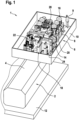
- An extruder 1 has an actuator 2 designed as a press cylinder and a hydraulic unit 6 according to the invention arranged on the top of its housing 4.
- This has a carrier 8 designed as a base plate. Since this can be accessed by operating personnel 9, a circumferential railing 10 is provided on the edge.
- the carrier 8 is attached directly to the housing 4 in a self-supporting manner and therefore does not require any further support structures to support it on the foundation 12 of the extruder 1.
- the press cylinder 2 is therefore easily accessible for maintenance and operation at any time.
- a tank 14 for storing the pressure medium is placed in the middle of the carrier 8.
- units 16 consisting of a hydraulic machine or pump and drive machine for supplying pressure medium to the press cylinder 2, storage units 18 for recuperating pressure medium energy, a cooling device 20 for recooling the pressure medium that heats up in the process, and hydraulic control blocks 22 Control of the pressure medium volume flows and thus of the press cylinder 2.
- the inlet and return lines 24, via which the tank and the hydraulic machines can be fluidically connected to the pressure chamber or chambers of the press cylinder are close to an edge-side gallery which is attached to the carrier 8 on the carrier 8 pierces.
- the pressure medium flow paths for supplying the press cylinder 2 are very short, which has already been discussed above with regard to the advantages.
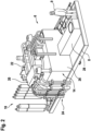
- FIG. 2 in which the gallery, the units 16 and the press cylinder 2 are hidden, shows this circumstance from a different perspective.
- the tank 14 has a central, cube-shaped main section 26 with a substantially square base area and a suction section or suction tunnel 28 which extends away from the main section in the longitudinal direction of the carrier 8.
- the latter acts as a large-volume inlet for the hydraulic machines of the units 16 Figure 1 and enables their fluidically short connection to the tank 14 and energy-efficient suction with a high volume flow.
- Figure 3 shows the unit 6 according to Figure 1 in a partial view from above.
- a hydraulic unit for an extruder with components for supplying pressure medium to an actuator of the extruder wherein, according to the invention, at least those of the components are arranged adjacently and supportingly connected, between which a high pressure medium volume flow and / or hydraulic power flow can be transferred.
- an extruder with the unit and a press cylinder, the unit being arranged on the press cylinder, in particular in a self-supporting manner, in order to minimize the length of the pressure medium flow paths between the unit and the press cylinder.
Landscapes
- Engineering & Computer Science (AREA)
- Mechanical Engineering (AREA)
- General Engineering & Computer Science (AREA)
- Physics & Mathematics (AREA)
- Fluid Mechanics (AREA)
- Chemical & Material Sciences (AREA)
- Analytical Chemistry (AREA)
- Supply Devices, Intensifiers, Converters, And Telemotors (AREA)
- Fluid-Pressure Circuits (AREA)
Description
- Die Erfindung betrifft ein Hydraulik-Aggregat für eine Strangpresse gemäß dem Oberbegriff des Patentanspruchs 1, eine Baureihe solcher Aggregate gemäß Patentanspruch 11, sowie eine Strangpresse mit dem Hydraulik-Aggregat gemäß Patentanspruch 13.
- Eine hydraulische Strangpresse hat einen Pressenzylinder und ein Hydraulik-Aggregat zu dessen Druckmittelversorgung. Letztgenanntes umfasst einen Tank zur Bevorratung des Druckmittels mit teils erheblichem Druckmittelvolumen, beispielsweise 20m3, sowie eine Pumpeneinheit oder -baugruppe mit mehreren Hydromaschinen, die aus dem Tank ansaugen. Zur Steuerung der Druckmittelversorgung ist eine hydraulische Steuereinrichtung, beispielsweise bestehend aus mehreren Hydraulik-Steuerblöcken, vorgesehen. Über einen Wärmetauscher erfolgt die Rückkühlung des Druckmittels.
- Die Pumpeneinheit ist bei einer herkömmlichen Strangpresse auf einer Ebene mit dem Pressenzylinder, bis zu 40m entfernt angeordnet. Der Tank und die Steuerblöcke sind hingegen oberhalb des Pressenzylinders, auf einer bodenseitig abgestützten Bühne angeordnet. Eine derartige Strangpresse mit Hydraulik-Aggregat zeigt beispielsweise die Druckschrift
WO 2013/167 111 A1 . - Damit nachteilig verbunden ist ein erschwerter Zugang zum Pressenzylinder, beispielsweise zur Wartung, aufgrund der Tragkonstruktion der Bühne. Die distanziert angeordnete Pumpeneinheit führt zu langen Druckmittelleitungen mit aufwändiger Verrohrung und entsprechendem Druckmittelvolumen. Dies trägt zur Brandlast bei und erschwert eine präzise Steuerung der Strangpresse. Zudem benötigt die Pumpeneinheit eine zusätzliche Aufstellfläche mit Fundament. Dieses Konzept der Anordnung des Hydraulik-Aggregats führt für verschiedene Leistungsklassen der Strangpresse zu einer jeweils individuellen Konzeption, was den konstruktiven Aufwand erhöht.
- Ein Hydraulik-Aggregat mit den Merkmalen des Oberbegriffs des Anspruchs 1 ist für die Strangpresse gemäß der Druckschrift
US 2,751,076 realisiert. Hierbei ist die Hydropumpe zur Versorgung des Pressenzylinders direkt auf dem Tank angeordnet. Die DruckschriftCN 106 180 234 A sowie die DruckschriftCN 204 583 884 U als auch die DruckschriftCN 202 028 626 U zeigen ebenfalls Strangpressen mit Hydraulik-Aggregaten. - Demgegenüber liegt der Erfindung die Aufgabe zugrunde, ein Hydraulik-Aggregat für eine Strangpresse zu schaffen, das kompakter aufgebaut ist. Eine weitere Aufgabe ist, eine Baureihe des Aggregats für verschiedene Leistungsklassen der Strangpresse mit verringertem Konstruktionsaufwand zu schaffen. Eine dritte Aufgabe ist, eine Strangpresse mit verringertem Platzbedarf zu schaffen.
- Die erste Aufgabe wird gelöst durch ein Hydraulik-Aggregat mit den Merkmalen des Patentanspruchs 1, die zweite Aufgabe wird gelöst durch eine Baureihe mit den Merkmalen des Anspruchs 11, und die dritte Aufgabe wird gelöst durch eine Strangpresse mit den Merkmalen des Anspruchs 13.
- Vorteilhafte Weiterbildungen sind in den jeweils abhängigen Ansprüchen beschrieben. Ein Hydraulik-Aggregat zur Druckmittelversorgung eines hydraulischen Aktors einer Strangpresse, insbesondere eines Pressenzylinders, hat mehrere Komponenten, insbesondere Hydraulik-Komponenten. Das Aggregat umfasst dabei als Komponenten zumindest einen Tank zur Bevorratung des Druckmittels, sowie wenigstens eine mit dem Tank fluidisch verbundene Hydromaschine, insbesondere Hydropumpe. Diese kann Druckmittel aus dem Tank ansaugen und ist ausgelegt, einen Druckraum des Aktors mit dem Druckmittel zu beaufschlagen. Dabei sind der Tank und die wenigstens eine Hydromaschine nicht nur fluidisch, sondern auch tragend miteinander verbunden. So bilden zumindest der Tank und die Hydromaschine nicht nur eine hydraulischfunktionale, sondern darüber hinaus auch eine bauliche Einheit. Dies ermöglicht, verglichen mit der verteilten Anordnung und lediglich fluidischen Verbindung von Tank und Hydromaschine herkömmlicher Aggregate, eine kompaktere Bauweise und Anordnung des Aggregats. Zudem wird auf diese Weise die tragende Struktur zusätzlich zur Ölführung zwischen dem Tank und der Hydromaschine verwendet, was den Stahlbau reduziert und Kosten senkt. Die tragende Verbindung von Tank und Hydromaschine legt zudem eine räumliche Nähe von Tank und Hydromaschine nahe, auf deren Vorteile später näher eingegangen wird. Erfindungsgemäß hat der Tank einen Hauptabschnitt oder ein Hauptvolumen, von dem sich wenigstens ein verjüngter Ansaugabschnitt, insbesondere ein Ansaugtunnel, erstreckt. Mit diesem ist ein Gehäuseanschluss, insbesondere Sauganschluss, der wenigstens einen Hydromaschine auf genannte Weise fluidisch verbunden. Der Ansaugabschnitt oder - tunnel ermöglicht eine Kombination aus optimierter Anordnung der wenigstens einen Hydromaschine, kurzem Druckmittelströmungspfad und optimaler Ansaugströmung im Tank.
- Als Komponenten umfasst das Aggregat in einer Weiterbildung zumindest eine Kühleinrichtung zur Rückkühlung des Druckmittels und/oder eine Steuereinrichtung zur Steuerung der Druckmittelversorgung und/oder eine hydraulische Speichereinheit zur Speicherung hydraulischer Energie und/oder einen Sauganschluss für den Aktor zum Anschluss einer Nachsaugleitung des Aktors und/oder weitere hydraulische, elektrische, mechanische Komponenten. Vorzugsweise sind diese, oder zumindest eine Auswahl davon, tragend mit dem Tank und der Hydromaschine verbunden.
- Zur Ausbildung der tragenden Verbindung ist in einer bevorzugten Weiterbildung ein gesonderter Träger, eine Platte oder eine Plattform vorgesehen, der oder die die genannten Komponenten unmittelbar oder mittelbar trägt. So sind die Komponenten auf einer gemeinsamen Ebene tragend verbunden angeordnet, anstatt auf mehreren Ebene verteilt angeordnet.
- Ein Vorteil ist auch, dass auf diesen Träger die Komponenten vormontiert werden können. Das vormontierte Aggregat ermöglicht einen einfacheren Transport hin zur Endmontage.
- Vorzugsweise ist die Hydromaschine mit einer Antriebsmaschine gekoppelt, die ebenso tragend verbunden, insbesondere auf dem Träger angeordnet ist.
- In einer besonders bevorzugten Weiterbildung ist der Träger bezüglich Statik und Durchbiegung derart robust ausgelegt, dass er frei- oder selbsttragend anordenbar ist.
- Freitragend bedeutet, dass der Träger nicht unmittelbar auf einem Fundament angeordnet sein muss und dass eine gesonderte Stützkonstruktion entfällt. Dadurch ist die Anordnung des Aggregats sehr flexibel möglich und die fehlende Stützkonstruktion macht Bauraum frei, der den Zugang, insbesondere für Wartungsarbeiten oder dergleichen erleichtert. Insbesondere kann der freitragende Träger dann direkt am Pressenzylinder angeordnet werden.
- Vorzugsweise weist der Träger zumindest für die wenigstens eine Hydromaschine und ihre Antriebsmaschine, sowie den Tank und die Speichereinheit, und optional die Kühleinrichtung, eine gesonderte Stellfläche auf. So sind zumindest die schwersten oder wartungsintensivsten der Komponenten gut zugänglich und unabhängig voneinander zu montieren/demontieren.
- In einer Weiterbildung sind der Tank und die wenigstens eine Hydromaschine benachbart angeordnet. Insbesondere ist ein Druckmittelströmungspfad von einem Sauganschluss der wenigstens einen Hydromaschine hin zum Tank kurz bemessen. So ergibt sich ein nur geringes Verbindungs-Druckmittelvolumen, was ein optimales Ansaugen ermöglicht. Entsprechend ist die Brandlast der Druckmittelmenge verringert, wodurch wiederum die Versicherungskosten gesenkt sind.
- Um den Druckmittelströmungspfad kurz zu halten ist in einer Weiterbildung saugseitiger Gehäuseanschluss der wenigstens einen Hydromaschine direkt oder über ein kurz bemessenes Saugrohr an den Tank geflanscht. Kurz ist im Sinne der Druckschrift beispielsweise so zu verstehen, dass ein Verhältnis gebildet aus der Länge des Druckmittelströmungspfades oder Saugrohres und einer charakteristischen Größe der Hydromaschine oder des Aggregats, beispielsweise dem Gehäusedurchmesser der Hydromaschine, kleiner oder bedeutend kleiner als 1 ist. Ein alternatives Kriterium für die Kürze ist beispielsweise, dass das im Druckmittelströmungspfad oder Saugrohr vorhandene Druckmittelvolumen bezogen auf das Druckmittelvolumen im Tank klein, insbesondere vernachlässigbar klein ist, beispielsweise im Bereich von 1/200 oder kleiner.
- Im Falle mehrerer Hydromaschinen und/oder Speichereinheiten sind diese bevorzugt beidseitig des oder der Tunnel verteilt angeordnet. Dies verbessert die individuelle Zugänglichkeit, verbessert eine Balance des Aggregats, ermöglicht eine noch kompaktere Anordnung der genannten Komponenten auf dem Träger und verringert so wiederum die potentielle Biegung des Trägers.
- Die Ansaugabschnitte sind in einer Weiterbildung, insbesondere in Abhängigkeit einer Optimierung der genannten Aspekte Länge des Druckmittelströmungspfades, Balance, Zugänglichkeit, Biegung oder dergleichen, am Hauptabschnitt asymmetrisch oder symmetrisch angeordnet und/oder ausgebildet.
- Besonders gut balanciert ist das Aggregat, sofern mehrere Hydromaschinen, insbesondere mit Antriebsmaschine, und/oder Speichereinheiten und/oder Kühleinheiten vorgesehen sind, diese entlang und/oder beidseitig des oder der Ansaugabschnitte angeordnet sind.
- Um die Strömung im Tank zu optimieren und so eine Entgasung zu beschleunigen, was wiederum zu geringerem Tankvolumen führt, hat der Tank in einer Weiterbildung mehrere kommunizierende Kompartimente oder Behälter. So ist eine Reduzierung des Tankvolumens um bis zu 75% möglich.
- Hierzu weist der Tank in einer Weiterbildung Leitbleche auf, über die er in die Kompartimente oder Behälter unterteilt ist.
- Diese können wiederum über kleinere Leitbleche unterteilt sein.
- Diesen Effekt, das Druckmittel im Tank schnell zu beruhigen, somit schnell zu entgasen und in Folge das Druckmittelvolumen zu reduzieren, hat auch eine Weiterbildung, bei der sich in den Tank hinein ein mit einem Druckraum des Aktors fluidisch verbindbarer Druckmittelrücklauf erstreckt, an dessen Mündung im Tank ein Diffusor zur Beruhigung einer Druckmittelrücklaufströmung vorgesehen ist.
- Beides, die Leitbleche und der Diffusor wirken somit in Richtung einer geringeren Druckmittelmenge, eines kleineren Tanks und dergleichen. Das senkt Investitionskosten und Betriebskosten.
- Vorzugsweise durchstößt eine Zulauf- oder Hochdruckleitung zur Druckmittelverbindung des Druckraums des Aktors mit einem Druckanschluss der wenigstens einen Hydromaschine und/oder von eine Niederdruck- oder Rücklaufleitung zum Nachsaugen von Druckmittel aus dem Tank in den Druckraum eine Ebene des Trägers in dessen Randbereich. Insbesondere bei Anordnung des Aggregats am Aktor sind auf dies Weise extrem kurze Druckmittelströmungspfade zum Nachsaugen und zur Druckmittelversorgung realisierbar, was seitens einer Energieeffizienz, dem vorrichtungstechnischen Aufwand, einer erzielbaren Steuerungs- oder Regelgüte und des Bauraumbedarfs große Vorteile mit sich bringt. Alternativ können die genannten Leitungen den Träger selbst durchsetzen, was in einem noch kompakteren Aggregat resultiert, wobei dabei jedoch auf ausreichende Stabilität des Trägers geachtet werden muss.
- Das Aggregat gemäß wenigstens einem Aspekt der vorhergehenden Beschreibung eignet sich durch die erfindungsgemäß tragende Verbindung von Tank und Hydromaschine(n) besonders gut für eine modulare Bauweise. Dadurch kann das Aggregat besonders gut auf verschiedene Nennleistungen skaliert werden wodurch der Konstruktionsaufwand für unterschiedliche Nennleistungen reduziert ist.
- Eine erfindungsgemäße Baureihe von Aggregaten weist daher Hydraulik-Aggregate unterschiedlicher Nennleistungen, also zur Druckmittelversorgung unterschiedlich leistungsstarker Strangpressen, auf, die jeweils gemäß wenigstens einem Aspekt der vorhergehenden Beschreibung ausgebildet sind. Dabei weisen die Aggregate insbesondere gleiche oder zumindest überwiegend gleiche Anordnungen ihrer Komponenten auf.
- Eine kostengünstige Standardisierung ist erzielbar, wenn in einer Weiterbildung über die Aggregate der Baureihe hinweg wenigstens eine der Komponenten ein Gleichteil ist.
- Eine erfindungsgemäße Strangpresse hat einen hydraulischen Aktor, insbesondere einen Pressenzylinder, und ein Hydraulik-Aggregat zu dessen Druckmittelversorgung, das nach wenigstens einem Aspekt der vorhergehenden Beschreibung ausgebildet ist.
- In einer Weiterbildung der Strangpresse, in der der Träger am Aktor freitragend, insbesondere an dessen Gehäuse oberseitig, angeordnet ist, ergeben sich die Vorteile, dass gesonderte Stellflächen und Fundamente für das Aggregat entfallen, ein Verrohrungs- und Verdrahtungsaufwand zwischen Aktor und Aggregat minimiert ist und der Aktor gut zugänglich ist.
- Im Folgenden wird ein Ausführungsbeispiel einer erfindungsgemäßen Strangpresse mit erfindungsgemäßem Hydraulik-Aggregat in drei Zeichnungen näher erläutert. Es zeigen:
-
Figur 1 eine Strangpresse mit einem Hydraulik-Aggregat und einem darüber mit Druckmittel versorgten Aktor, gemäß einem Ausführungsbeispiel in einer perspektivischen Ansicht, -
Figur 2 das Aggregat gemäßFigur 1 mit entfernten Hydromaschinen, in perspektivischer Ansicht, und -
Figur 3 die Strangpresse gemäßFigur 1 in einer Ansicht von oben. - Gemäß
Figur 1 hat eine Strangpresse 1 einen als Pressenzylinder ausgestalteten Aktor 2 und an dessen Gehäuse 4 oberseitig angeordnet ein erfindungsgemäßes Hydraulik-Aggregat 6. Dieses hat einen als Grundplatte ausgestalteten Träger 8. Da dieser von Bedienpersonal 9 betretbar ist, ist randseitig ein umlaufendes Geländer 10 vorgesehen. Der Träger 8 ist direkt am Gehäuse 4 freitragend befestigt und benötigt daher keine weiteren Stützkonstruktionen, um ihm am Fundament 12 der Strangpresse 1 abzustützen. Der Pressenzylinder 2 ist so für Wartung und Betrieb zu jedem Zeitpunkt gut zugänglich. - Mittig auf dem Träger 8 ist ein Tank 14 zur Bevorratung des Druckmittels platziert. Um diesen herum sind weitere Komponenten des Aggregats 8, insbesondere Einheiten 16 aus Hydromaschine oder -pumpe und Antriebmaschine zur Druckmittelversorgung des Pressenzylinders 2, Speichereinheiten 18 zur Rekuperation von Druckmittelenergie, eine Kühleinrichtung 20 zur Rückkühlung des sich im Prozess erwärmenden Druckmittels, sowie hydraulische Steuerblöcke 22 zur Steuerung der Druckmittelvolumenströme und damit des Pressenzylinders 2. Gut zu erkennen ist, dass Zulauf und Rücklaufleitungen 24, über die der Tank und die Hydromaschinen mit dem oder den Druckräumen des Pressenzylinders fluidisch verbindbar sind, eine randseitige Galerie, die am Träger 8 befestigt ist, nahe am Träger 8 durchstößt. So sind die Druckmittelströmungspfade zur Versorgung des Pressenzylinders 2 sehr kurz, was bezüglich der Vorteile bereits weiter oben besprochen wurde.
-
Figur 2 , in der die Galerie, die Einheiten 16 und der Pressenzylinder 2 ausgeblendet sind, zeigt diesen Umstand aus anderer Perspektive. Hier ist auch gut ersichtlich, dass der Tank 14 einen mittigen, würfelförmigen Hauptabschnitt 26 mit im Wesentlichen quadratischer Grundfläche und einen sich in Längsrichtung des Trägers 8 vom Hauptabschnitt wegerstreckenden Ansaugabschnitt oder Ansaugtunnel 28 hat. Letztgenannter fungiert als großvolumiger Zulauf für die Hydromaschinen der Einheiten 16 gemäßFigur 1 und ermöglicht deren fluidisch kurze Anbindung an den Tank 14 und das energieeffiziente Ansaugen mit hohem Volumenstrom. -
Figur 3 zeigt das Aggregat 6 gemäßFigur 1 in einer Teilansicht von oben. - Offenbart ist ein Hydraulik-Aggregat für eine Strangpresse mit Komponenten zur Druckmittelversorgung eines Aktors der Strangpresse, wobei erfindungsgemäß zumindest diejenigen der Komponenten benachbart angeordnet und tragend verbunden sind, zwischen denen ein hoher Druckmittelvolumenstrom und/oder hydraulischer Leistungsstrom übertragbar ist.
- Offenbart ist zudem eine Baureihe solcher Aggregate mit unterschiedlicher Nennleistung aber gleicher Topologie der Komponenten.
- Offenbart ist zudem eine Strangpresse mit dem Aggregat und einem Pressenzylinder, wobei das Aggregat zur Minimierung der Länge der Druckmittelströmungspfade zwischen Aggregat und Pressenzylinder am Pressenzylinder, insbesondere freitragend, angeordnet ist.
-
- 1 hydraulische Strangpresse
- 2 Pressenzylinder
- 4 Gehäuse
- 6 Hydraulik-Aggregat
- 8 Träger
- 9 Bedienpersonal
- 10 Geländer
- 12 Fundament
- 14 Tank
- 16 Hydromaschinen-Antriebsmaschinen Einheit
- 18 Speichereinheit
- 20 Kühleinrichtung
- 22 hydraulischer Steuerblock
- 24 Zulauf- / Rücklaufleitung
- 26 Hauptabschnitt
- 28 Ansaugtunnel
Claims (14)
- Hydraulik-Aggregat zur Druckmittelversorgung eines hydraulischen Aktors (2) einer Strangpresse (1), das zumindest einen Tank (14) zur Bevorratung von Druckmittel und wenigstens eine mit diesem fluidisch verbundene Hydromaschine (16) zur Beaufschlagung des Aktors (2) mit Druckmittel umfasst, wobei der Tank (14) und die wenigstens eine Hydromaschine (16) tragend verbunden sind, dadurch gekennzeichnet, dass der Tank (14) einen Hauptabschnitt (26) hat, von dem sich ein verjüngter Ansaugabschnitt (28) erstreckt, mit dem ein Gehäuseanschluss, insbesondere Sauganschluss, der wenigstens einen Hydromaschine (16) fluidisch verbunden ist.
- Aggregat nach Anspruch 1 mit einem Träger (8), an dem wenigstens der Tank (14) und die wenigstens eine Hydromaschine (16) angeordnet sind.
- Aggregat nach Anspruch 2, wobei der Träger (8) freitragend anordenbar ausgelegt ist.
- Aggregat nach einem der vorhergehenden Ansprüche, wobei der Tank (14) und die wenigstens eine Hydromaschine (16) benachbart angeordnet sind.
- Aggregat nach einem der vorhergehenden Ansprüche, wobei ein Druckmittelströmungspfad von einem Sauganschluss der wenigstens einen Hydromaschine (16) hin zum Tank (14) kurz bemessen ist.
- Aggregat nach einem der vorhergehenden Ansprüche, wobei ein Gehäuseanschluss der wenigstens einen Hydromaschine direkt oder über ein kurz bemessenes Saugrohr an den Tank (14) geflanscht ist.
- Aggregat nach einem der vorgehenden Ansprüche mit mehreren Ansaugabschnitten, die am Hauptabschnitt asymmetrisch oder symmetrisch angeordnet und/oder ausgebildet sind.
- Aggregat nach einem der vorgehenden Ansprüche mit mehreren Hydromaschinen (16), die entlang und/oder beidseitig des Ansaugabschnitts (28) oder der Ansaugabschnitte angeordnet sind.
- Aggregat nach einem der vorhergehenden Ansprüche, wobei der Tank (14) mehrere kommunizierende Kompartimente oder Behälter aufweist.
- Aggregat nach einem der der vorhergehenden Ansprüche, wobei sich in den Tank (14) hinein ein mit einem Druckraum des Aktors fluidisch verbindbarer Druckmittelrücklauf (24) erstreckt, an dessen Mündung im Tank ein Diffusor vorgesehen ist.
- Baureihe mit Hydraulik-Aggregaten unterschiedlicher Nennleistung, die jeweils gemäß einem der vorhergehenden Ansprüche ausgebildet sind, wobei die Aggregate gleiche oder zumindest überwiegend gleiche Anordnungen ihrer Komponenten aufweisen.
- Baureihe nach Anspruch 11, wobei wenigstens eine Komponente von wenigstens zwei der Aggregate ein Gleichteil ist.
- Strangpresse mit einem hydraulischen Aktor (2), insbesondere Pressenzylinder, und mit einem Hydraulik-Aggregat (6) zu dessen Druckmittelversorgung, das nach einem der Ansprüche 1 bis 10 ausgebildet ist.
- Strangpresse nach Anspruch 13 mit dem Aggregat (6) nach Anspruch 2 oder einem darauf rückbezogenen Anspruch, wobei der Träger (8) zumindest im Nahbereich des Aktors oder an diesem (2) freitragend angeordnet ist.
Applications Claiming Priority (1)
| Application Number | Priority Date | Filing Date | Title |
|---|---|---|---|
| DE102020207274.4A DE102020207274B3 (de) | 2020-06-10 | 2020-06-10 | Hydraulik-Aggregat für eine Strangpresse, Baureihe derartiger Aggregate und Strangpresse mit dem Hydraulik-Aggregat |
Publications (2)
| Publication Number | Publication Date |
|---|---|
| EP3922449A1 EP3922449A1 (de) | 2021-12-15 |
| EP3922449B1 true EP3922449B1 (de) | 2023-10-11 |
Family
ID=76197286
Family Applications (1)
| Application Number | Title | Priority Date | Filing Date |
|---|---|---|---|
| EP21176775.1A Active EP3922449B1 (de) | 2020-06-10 | 2021-05-31 | Hydraulik-aggregat für eine strangpresse baureihe derartiger aggregate und strangpresse mit dem hydraulik-aggregat |
Country Status (3)
| Country | Link |
|---|---|
| EP (1) | EP3922449B1 (de) |
| CN (1) | CN113775576A (de) |
| DE (1) | DE102020207274B3 (de) |
Family Cites Families (12)
| Publication number | Priority date | Publication date | Assignee | Title |
|---|---|---|---|---|
| US2751076A (en) | 1953-02-16 | 1956-06-19 | Daniel L Lombard | Extrusion press installation |
| GB860075A (en) * | 1956-07-23 | 1961-02-01 | Von Roll Ag | Improvements in or relating to control apparatus in hydrostatic power transmission sy |
| CN2356756Y (zh) * | 1999-01-28 | 2000-01-05 | 宝山钢铁(集团)公司 | 冷轧彩涂机组涂料自动输送装置 |
| AT507087B1 (de) * | 2008-12-05 | 2010-02-15 | Siemens Vai Metals Tech Gmbh | Verfahren und vorrichtung zur semi-aktiven reduktion von druckschwingungen in einem hydrauliksystem |
| JP5021848B2 (ja) * | 2009-07-27 | 2012-09-12 | オイルギア タウラー ソシエテ パル アクスィオン サンプリフィエ | 金属成形機等の加工機を液圧により作動させるための装置及びこのような金属成形機を作動させるための方法 |
| CN202028626U (zh) * | 2011-03-23 | 2011-11-09 | 昆山捷安特轻合金科技有限公司 | 结构改良的挤压机油路 |
| DE102012009182A1 (de) | 2012-05-10 | 2013-11-14 | Sms Meer Gmbh | Hydraulische Strangpresse sowie Verfahren zum Betrieb einer hydraulischen Strangpresse |
| DE102013114040A1 (de) * | 2013-12-13 | 2015-06-18 | Linde Hydraulics Gmbh & Co. Kg | Hydrostatischer Antrieb mit Energiespeicherung |
| CN203756618U (zh) * | 2014-03-11 | 2014-08-06 | 江西京冶科技有限责任公司 | 一种轧机传动站液压系统 |
| DE102014210311A1 (de) * | 2014-06-02 | 2015-12-03 | Robert Bosch Gmbh | Antrieb mit Schnellschlussfunktion und Verfahren für einen derartigen Antrieb |
| CN204583884U (zh) * | 2015-02-16 | 2015-08-26 | 梁润明 | 节能、高效、闭式加压供油型材挤压机 |
| CN106180234A (zh) * | 2016-07-20 | 2016-12-07 | 佛山市业精机械制造有限公司 | 一种低速铝型材挤压机 |
-
2020
- 2020-06-10 DE DE102020207274.4A patent/DE102020207274B3/de not_active Expired - Fee Related
-
2021
- 2021-05-31 EP EP21176775.1A patent/EP3922449B1/de active Active
- 2021-06-09 CN CN202110642107.6A patent/CN113775576A/zh active Pending
Also Published As
| Publication number | Publication date |
|---|---|
| EP3922449A1 (de) | 2021-12-15 |
| DE102020207274B3 (de) | 2021-10-14 |
| CN113775576A (zh) | 2021-12-10 |
Similar Documents
| Publication | Publication Date | Title |
|---|---|---|
| DE3715712C1 (de) | Waermetauscher insbesondere zum Kuehlen von Spaltgas | |
| DE19537482A1 (de) | Hydraulischer Steuerblock | |
| EP2464868B1 (de) | Membranmaschine | |
| EP2636958A2 (de) | Heizkreisverteiler mit integrierter hydraulischer Weiche | |
| DE102021201804A1 (de) | Gehäuse für eine elektrische Maschine mit einem sich selbst entlüftenden Kühlmantel | |
| DE102020207274B3 (de) | Hydraulik-Aggregat für eine Strangpresse, Baureihe derartiger Aggregate und Strangpresse mit dem Hydraulik-Aggregat | |
| DE102009015212A1 (de) | Vorrichtung zum Homogenisieren eines Eintrittsstroms in einem Plattenwärmetauscher | |
| DE102013015519A1 (de) | Vorrichtung zum Speichern von Gas | |
| EP3044531B1 (de) | Hochdruckplattenwärmetauscher | |
| EP1399678B1 (de) | Pumpe zur förderung eines wärmetauschmittels für einen kontaktrohrbündelreaktor | |
| DE102014223524A1 (de) | Maschinenrahmen für eine Rollenpresse | |
| EP1988353A2 (de) | Kühler für ein Kraftfahrzeug | |
| DE102009045221A1 (de) | Turbulenzerzeuger für einen Stoffauflauf, Stoffauflauf und Verfahren zur Herstellung des Turbulenzerzeugers | |
| DE102017130286A1 (de) | Vorrichtung zum Austausch eines Gewebes in einer Bahnbildungsmaschine | |
| EP4074983B1 (de) | Hydraulisches aggregat und vorrichtung mit dem aggregat | |
| EP3866979A1 (de) | Hebelsystem zur kraftübertragung | |
| EP4074984A1 (de) | Hydraulikblock und verfahren | |
| CH650558A5 (de) | Messerschild-steuerung. | |
| EP3596390B1 (de) | Roststab, rost und verbrennungsanlage | |
| DE10009179C2 (de) | Wärmeübertrager in Plattenbauweise | |
| EP3030784A1 (de) | Verdrängerpumpe | |
| EP3738694A1 (de) | Hydraulik-vorrichtung für eine druckgiessmaschine | |
| EP1452817A1 (de) | Wärmetauscher | |
| DE2849990A1 (de) | Gekuehlte regelklappe fuer heissgasleitungen | |
| DE102011103635A1 (de) | Wärmeübertrager |
Legal Events
| Date | Code | Title | Description |
|---|---|---|---|
| PUAI | Public reference made under article 153(3) epc to a published international application that has entered the european phase |
Free format text: ORIGINAL CODE: 0009012 |
|
| STAA | Information on the status of an ep patent application or granted ep patent |
Free format text: STATUS: THE APPLICATION HAS BEEN PUBLISHED |
|
| AK | Designated contracting states |
Kind code of ref document: A1 Designated state(s): AL AT BE BG CH CY CZ DE DK EE ES FI FR GB GR HR HU IE IS IT LI LT LU LV MC MK MT NL NO PL PT RO RS SE SI SK SM TR |
|
| B565 | Issuance of search results under rule 164(2) epc |
Effective date: 20211111 |
|
| STAA | Information on the status of an ep patent application or granted ep patent |
Free format text: STATUS: REQUEST FOR EXAMINATION WAS MADE |
|
| 17P | Request for examination filed |
Effective date: 20220615 |
|
| RBV | Designated contracting states (corrected) |
Designated state(s): AL AT BE BG CH CY CZ DE DK EE ES FI FR GB GR HR HU IE IS IT LI LT LU LV MC MK MT NL NO PL PT RO RS SE SI SK SM TR |
|
| GRAP | Despatch of communication of intention to grant a patent |
Free format text: ORIGINAL CODE: EPIDOSNIGR1 |
|
| STAA | Information on the status of an ep patent application or granted ep patent |
Free format text: STATUS: GRANT OF PATENT IS INTENDED |
|
| RIC1 | Information provided on ipc code assigned before grant |
Ipc: F15B 1/26 20060101ALI20230630BHEP Ipc: B21C 23/21 20060101ALI20230630BHEP Ipc: B30B 11/26 20060101AFI20230630BHEP |
|
| INTG | Intention to grant announced |
Effective date: 20230728 |
|
| GRAS | Grant fee paid |
Free format text: ORIGINAL CODE: EPIDOSNIGR3 |
|
| GRAA | (expected) grant |
Free format text: ORIGINAL CODE: 0009210 |
|
| STAA | Information on the status of an ep patent application or granted ep patent |
Free format text: STATUS: THE PATENT HAS BEEN GRANTED |
|
| AK | Designated contracting states |
Kind code of ref document: B1 Designated state(s): AL AT BE BG CH CY CZ DE DK EE ES FI FR GB GR HR HU IE IS IT LI LT LU LV MC MK MT NL NO PL PT RO RS SE SI SK SM TR |
|
| REG | Reference to a national code |
Ref country code: GB Ref legal event code: FG4D Free format text: NOT ENGLISH |
|
| REG | Reference to a national code |
Ref country code: CH Ref legal event code: EP |
|
| REG | Reference to a national code |
Ref country code: DE Ref legal event code: R096 Ref document number: 502021001667 Country of ref document: DE |
|
| REG | Reference to a national code |
Ref country code: IE Ref legal event code: FG4D Free format text: LANGUAGE OF EP DOCUMENT: GERMAN |
|
| REG | Reference to a national code |
Ref country code: LT Ref legal event code: MG9D |
|
| REG | Reference to a national code |
Ref country code: NL Ref legal event code: MP Effective date: 20231011 |
|
| PG25 | Lapsed in a contracting state [announced via postgrant information from national office to epo] |
Ref country code: NL Free format text: LAPSE BECAUSE OF FAILURE TO SUBMIT A TRANSLATION OF THE DESCRIPTION OR TO PAY THE FEE WITHIN THE PRESCRIBED TIME-LIMIT Effective date: 20231011 |
|
| PG25 | Lapsed in a contracting state [announced via postgrant information from national office to epo] |
Ref country code: GR Free format text: LAPSE BECAUSE OF FAILURE TO SUBMIT A TRANSLATION OF THE DESCRIPTION OR TO PAY THE FEE WITHIN THE PRESCRIBED TIME-LIMIT Effective date: 20240112 |
|
| PG25 | Lapsed in a contracting state [announced via postgrant information from national office to epo] |
Ref country code: IS Free format text: LAPSE BECAUSE OF FAILURE TO SUBMIT A TRANSLATION OF THE DESCRIPTION OR TO PAY THE FEE WITHIN THE PRESCRIBED TIME-LIMIT Effective date: 20240211 |
|
| PG25 | Lapsed in a contracting state [announced via postgrant information from national office to epo] |
Ref country code: LT Free format text: LAPSE BECAUSE OF FAILURE TO SUBMIT A TRANSLATION OF THE DESCRIPTION OR TO PAY THE FEE WITHIN THE PRESCRIBED TIME-LIMIT Effective date: 20231011 |
|
| PG25 | Lapsed in a contracting state [announced via postgrant information from national office to epo] |
Ref country code: ES Free format text: LAPSE BECAUSE OF FAILURE TO SUBMIT A TRANSLATION OF THE DESCRIPTION OR TO PAY THE FEE WITHIN THE PRESCRIBED TIME-LIMIT Effective date: 20231011 |
|
| PG25 | Lapsed in a contracting state [announced via postgrant information from national office to epo] |
Ref country code: LT Free format text: LAPSE BECAUSE OF FAILURE TO SUBMIT A TRANSLATION OF THE DESCRIPTION OR TO PAY THE FEE WITHIN THE PRESCRIBED TIME-LIMIT Effective date: 20231011 Ref country code: IS Free format text: LAPSE BECAUSE OF FAILURE TO SUBMIT A TRANSLATION OF THE DESCRIPTION OR TO PAY THE FEE WITHIN THE PRESCRIBED TIME-LIMIT Effective date: 20240211 Ref country code: GR Free format text: LAPSE BECAUSE OF FAILURE TO SUBMIT A TRANSLATION OF THE DESCRIPTION OR TO PAY THE FEE WITHIN THE PRESCRIBED TIME-LIMIT Effective date: 20240112 Ref country code: ES Free format text: LAPSE BECAUSE OF FAILURE TO SUBMIT A TRANSLATION OF THE DESCRIPTION OR TO PAY THE FEE WITHIN THE PRESCRIBED TIME-LIMIT Effective date: 20231011 Ref country code: BG Free format text: LAPSE BECAUSE OF FAILURE TO SUBMIT A TRANSLATION OF THE DESCRIPTION OR TO PAY THE FEE WITHIN THE PRESCRIBED TIME-LIMIT Effective date: 20240111 Ref country code: PT Free format text: LAPSE BECAUSE OF FAILURE TO SUBMIT A TRANSLATION OF THE DESCRIPTION OR TO PAY THE FEE WITHIN THE PRESCRIBED TIME-LIMIT Effective date: 20240212 |
|
| PG25 | Lapsed in a contracting state [announced via postgrant information from national office to epo] |
Ref country code: SE Free format text: LAPSE BECAUSE OF FAILURE TO SUBMIT A TRANSLATION OF THE DESCRIPTION OR TO PAY THE FEE WITHIN THE PRESCRIBED TIME-LIMIT Effective date: 20231011 Ref country code: RS Free format text: LAPSE BECAUSE OF FAILURE TO SUBMIT A TRANSLATION OF THE DESCRIPTION OR TO PAY THE FEE WITHIN THE PRESCRIBED TIME-LIMIT Effective date: 20231011 Ref country code: PL Free format text: LAPSE BECAUSE OF FAILURE TO SUBMIT A TRANSLATION OF THE DESCRIPTION OR TO PAY THE FEE WITHIN THE PRESCRIBED TIME-LIMIT Effective date: 20231011 Ref country code: NO Free format text: LAPSE BECAUSE OF FAILURE TO SUBMIT A TRANSLATION OF THE DESCRIPTION OR TO PAY THE FEE WITHIN THE PRESCRIBED TIME-LIMIT Effective date: 20240111 Ref country code: LV Free format text: LAPSE BECAUSE OF FAILURE TO SUBMIT A TRANSLATION OF THE DESCRIPTION OR TO PAY THE FEE WITHIN THE PRESCRIBED TIME-LIMIT Effective date: 20231011 Ref country code: HR Free format text: LAPSE BECAUSE OF FAILURE TO SUBMIT A TRANSLATION OF THE DESCRIPTION OR TO PAY THE FEE WITHIN THE PRESCRIBED TIME-LIMIT Effective date: 20231011 |
|
| PG25 | Lapsed in a contracting state [announced via postgrant information from national office to epo] |
Ref country code: DK Free format text: LAPSE BECAUSE OF FAILURE TO SUBMIT A TRANSLATION OF THE DESCRIPTION OR TO PAY THE FEE WITHIN THE PRESCRIBED TIME-LIMIT Effective date: 20231011 |
|
| REG | Reference to a national code |
Ref country code: DE Ref legal event code: R097 Ref document number: 502021001667 Country of ref document: DE |
|
| PG25 | Lapsed in a contracting state [announced via postgrant information from national office to epo] |
Ref country code: CZ Free format text: LAPSE BECAUSE OF FAILURE TO SUBMIT A TRANSLATION OF THE DESCRIPTION OR TO PAY THE FEE WITHIN THE PRESCRIBED TIME-LIMIT Effective date: 20231011 |
|
| PG25 | Lapsed in a contracting state [announced via postgrant information from national office to epo] |
Ref country code: SK Free format text: LAPSE BECAUSE OF FAILURE TO SUBMIT A TRANSLATION OF THE DESCRIPTION OR TO PAY THE FEE WITHIN THE PRESCRIBED TIME-LIMIT Effective date: 20231011 |
|
| PG25 | Lapsed in a contracting state [announced via postgrant information from national office to epo] |
Ref country code: SM Free format text: LAPSE BECAUSE OF FAILURE TO SUBMIT A TRANSLATION OF THE DESCRIPTION OR TO PAY THE FEE WITHIN THE PRESCRIBED TIME-LIMIT Effective date: 20231011 Ref country code: SK Free format text: LAPSE BECAUSE OF FAILURE TO SUBMIT A TRANSLATION OF THE DESCRIPTION OR TO PAY THE FEE WITHIN THE PRESCRIBED TIME-LIMIT Effective date: 20231011 Ref country code: RO Free format text: LAPSE BECAUSE OF FAILURE TO SUBMIT A TRANSLATION OF THE DESCRIPTION OR TO PAY THE FEE WITHIN THE PRESCRIBED TIME-LIMIT Effective date: 20231011 Ref country code: IT Free format text: LAPSE BECAUSE OF FAILURE TO SUBMIT A TRANSLATION OF THE DESCRIPTION OR TO PAY THE FEE WITHIN THE PRESCRIBED TIME-LIMIT Effective date: 20231011 Ref country code: EE Free format text: LAPSE BECAUSE OF FAILURE TO SUBMIT A TRANSLATION OF THE DESCRIPTION OR TO PAY THE FEE WITHIN THE PRESCRIBED TIME-LIMIT Effective date: 20231011 Ref country code: DK Free format text: LAPSE BECAUSE OF FAILURE TO SUBMIT A TRANSLATION OF THE DESCRIPTION OR TO PAY THE FEE WITHIN THE PRESCRIBED TIME-LIMIT Effective date: 20231011 Ref country code: CZ Free format text: LAPSE BECAUSE OF FAILURE TO SUBMIT A TRANSLATION OF THE DESCRIPTION OR TO PAY THE FEE WITHIN THE PRESCRIBED TIME-LIMIT Effective date: 20231011 |
|
| PLBE | No opposition filed within time limit |
Free format text: ORIGINAL CODE: 0009261 |
|
| STAA | Information on the status of an ep patent application or granted ep patent |
Free format text: STATUS: NO OPPOSITION FILED WITHIN TIME LIMIT |
|
| 26N | No opposition filed |
Effective date: 20240712 |
|
| PG25 | Lapsed in a contracting state [announced via postgrant information from national office to epo] |
Ref country code: SI Free format text: LAPSE BECAUSE OF FAILURE TO SUBMIT A TRANSLATION OF THE DESCRIPTION OR TO PAY THE FEE WITHIN THE PRESCRIBED TIME-LIMIT Effective date: 20231011 |
|
| PG25 | Lapsed in a contracting state [announced via postgrant information from national office to epo] |
Ref country code: SI Free format text: LAPSE BECAUSE OF FAILURE TO SUBMIT A TRANSLATION OF THE DESCRIPTION OR TO PAY THE FEE WITHIN THE PRESCRIBED TIME-LIMIT Effective date: 20231011 |
|
| REG | Reference to a national code |
Ref country code: CH Ref legal event code: PL |
|
| PG25 | Lapsed in a contracting state [announced via postgrant information from national office to epo] |
Ref country code: MC Free format text: LAPSE BECAUSE OF FAILURE TO SUBMIT A TRANSLATION OF THE DESCRIPTION OR TO PAY THE FEE WITHIN THE PRESCRIBED TIME-LIMIT Effective date: 20231011 |
|
| PG25 | Lapsed in a contracting state [announced via postgrant information from national office to epo] |
Ref country code: LU Free format text: LAPSE BECAUSE OF NON-PAYMENT OF DUE FEES Effective date: 20240531 |
|
| PG25 | Lapsed in a contracting state [announced via postgrant information from national office to epo] |
Ref country code: MC Free format text: LAPSE BECAUSE OF FAILURE TO SUBMIT A TRANSLATION OF THE DESCRIPTION OR TO PAY THE FEE WITHIN THE PRESCRIBED TIME-LIMIT Effective date: 20231011 Ref country code: LU Free format text: LAPSE BECAUSE OF NON-PAYMENT OF DUE FEES Effective date: 20240531 Ref country code: CH Free format text: LAPSE BECAUSE OF NON-PAYMENT OF DUE FEES Effective date: 20240531 |
|
| REG | Reference to a national code |
Ref country code: BE Ref legal event code: MM Effective date: 20240531 |
|
| PG25 | Lapsed in a contracting state [announced via postgrant information from national office to epo] |
Ref country code: IE Free format text: LAPSE BECAUSE OF NON-PAYMENT OF DUE FEES Effective date: 20240531 |
|
| PG25 | Lapsed in a contracting state [announced via postgrant information from national office to epo] |
Ref country code: BE Free format text: LAPSE BECAUSE OF NON-PAYMENT OF DUE FEES Effective date: 20240531 |
|
| PG25 | Lapsed in a contracting state [announced via postgrant information from national office to epo] |
Ref country code: FR Free format text: LAPSE BECAUSE OF NON-PAYMENT OF DUE FEES Effective date: 20240531 |
|
| PGFP | Annual fee paid to national office [announced via postgrant information from national office to epo] |
Ref country code: AT Payment date: 20250721 Year of fee payment: 5 |
|
| PG25 | Lapsed in a contracting state [announced via postgrant information from national office to epo] |
Ref country code: CY Free format text: LAPSE BECAUSE OF FAILURE TO SUBMIT A TRANSLATION OF THE DESCRIPTION OR TO PAY THE FEE WITHIN THE PRESCRIBED TIME-LIMIT; INVALID AB INITIO Effective date: 20210531 |
|
| PG25 | Lapsed in a contracting state [announced via postgrant information from national office to epo] |
Ref country code: FI Free format text: LAPSE BECAUSE OF FAILURE TO SUBMIT A TRANSLATION OF THE DESCRIPTION OR TO PAY THE FEE WITHIN THE PRESCRIBED TIME-LIMIT Effective date: 20231011 |
|
| PGFP | Annual fee paid to national office [announced via postgrant information from national office to epo] |
Ref country code: DE Payment date: 20250716 Year of fee payment: 5 |
|
| GBPC | Gb: european patent ceased through non-payment of renewal fee |
Effective date: 20250531 |
|
| PG25 | Lapsed in a contracting state [announced via postgrant information from national office to epo] |
Ref country code: HU Free format text: LAPSE BECAUSE OF FAILURE TO SUBMIT A TRANSLATION OF THE DESCRIPTION OR TO PAY THE FEE WITHIN THE PRESCRIBED TIME-LIMIT; INVALID AB INITIO Effective date: 20210531 |
|
| PG25 | Lapsed in a contracting state [announced via postgrant information from national office to epo] |
Ref country code: GB Free format text: LAPSE BECAUSE OF NON-PAYMENT OF DUE FEES Effective date: 20250531 |