EP3922393A1 - Welding control device, welding control method, and welding control program - Google Patents
Welding control device, welding control method, and welding control program Download PDFInfo
- Publication number
- EP3922393A1 EP3922393A1 EP20802435.6A EP20802435A EP3922393A1 EP 3922393 A1 EP3922393 A1 EP 3922393A1 EP 20802435 A EP20802435 A EP 20802435A EP 3922393 A1 EP3922393 A1 EP 3922393A1
- Authority
- EP
- European Patent Office
- Prior art keywords
- welding
- electrode
- control
- target
- feature amount
- Prior art date
- Legal status (The legal status is an assumption and is not a legal conclusion. Google has not performed a legal analysis and makes no representation as to the accuracy of the status listed.)
- Granted
Links
Images







Classifications
-
- B—PERFORMING OPERATIONS; TRANSPORTING
- B23—MACHINE TOOLS; METAL-WORKING NOT OTHERWISE PROVIDED FOR
- B23K—SOLDERING OR UNSOLDERING; WELDING; CLADDING OR PLATING BY SOLDERING OR WELDING; CUTTING BY APPLYING HEAT LOCALLY, e.g. FLAME CUTTING; WORKING BY LASER BEAM
- B23K9/00—Arc welding or cutting
- B23K9/12—Automatic feeding or moving of electrodes or work for spot or seam welding or cutting
- B23K9/124—Circuits or methods for feeding welding wire
-
- B—PERFORMING OPERATIONS; TRANSPORTING
- B23—MACHINE TOOLS; METAL-WORKING NOT OTHERWISE PROVIDED FOR
- B23K—SOLDERING OR UNSOLDERING; WELDING; CLADDING OR PLATING BY SOLDERING OR WELDING; CUTTING BY APPLYING HEAT LOCALLY, e.g. FLAME CUTTING; WORKING BY LASER BEAM
- B23K9/00—Arc welding or cutting
- B23K9/095—Monitoring or automatic control of welding parameters
- B23K9/0953—Monitoring or automatic control of welding parameters using computing means
-
- B—PERFORMING OPERATIONS; TRANSPORTING
- B23—MACHINE TOOLS; METAL-WORKING NOT OTHERWISE PROVIDED FOR
- B23K—SOLDERING OR UNSOLDERING; WELDING; CLADDING OR PLATING BY SOLDERING OR WELDING; CUTTING BY APPLYING HEAT LOCALLY, e.g. FLAME CUTTING; WORKING BY LASER BEAM
- B23K31/00—Processes relevant to this subclass, specially adapted for particular articles or purposes, but not covered by any single one of main groups B23K1/00 - B23K28/00
- B23K31/006—Processes relevant to this subclass, specially adapted for particular articles or purposes, but not covered by any single one of main groups B23K1/00 - B23K28/00 relating to using of neural networks
-
- B—PERFORMING OPERATIONS; TRANSPORTING
- B23—MACHINE TOOLS; METAL-WORKING NOT OTHERWISE PROVIDED FOR
- B23K—SOLDERING OR UNSOLDERING; WELDING; CLADDING OR PLATING BY SOLDERING OR WELDING; CUTTING BY APPLYING HEAT LOCALLY, e.g. FLAME CUTTING; WORKING BY LASER BEAM
- B23K9/00—Arc welding or cutting
- B23K9/095—Monitoring or automatic control of welding parameters
- B23K9/0956—Monitoring or automatic control of welding parameters using sensing means, e.g. optical
-
- B—PERFORMING OPERATIONS; TRANSPORTING
- B23—MACHINE TOOLS; METAL-WORKING NOT OTHERWISE PROVIDED FOR
- B23K—SOLDERING OR UNSOLDERING; WELDING; CLADDING OR PLATING BY SOLDERING OR WELDING; CUTTING BY APPLYING HEAT LOCALLY, e.g. FLAME CUTTING; WORKING BY LASER BEAM
- B23K9/00—Arc welding or cutting
- B23K9/10—Other electric circuits therefor; Protective circuits; Remote controls
-
- B—PERFORMING OPERATIONS; TRANSPORTING
- B23—MACHINE TOOLS; METAL-WORKING NOT OTHERWISE PROVIDED FOR
- B23K—SOLDERING OR UNSOLDERING; WELDING; CLADDING OR PLATING BY SOLDERING OR WELDING; CUTTING BY APPLYING HEAT LOCALLY, e.g. FLAME CUTTING; WORKING BY LASER BEAM
- B23K9/00—Arc welding or cutting
- B23K9/12—Automatic feeding or moving of electrodes or work for spot or seam welding or cutting
- B23K9/127—Means for tracking lines during arc welding or cutting
-
- B—PERFORMING OPERATIONS; TRANSPORTING
- B23—MACHINE TOOLS; METAL-WORKING NOT OTHERWISE PROVIDED FOR
- B23K—SOLDERING OR UNSOLDERING; WELDING; CLADDING OR PLATING BY SOLDERING OR WELDING; CUTTING BY APPLYING HEAT LOCALLY, e.g. FLAME CUTTING; WORKING BY LASER BEAM
- B23K9/00—Arc welding or cutting
- B23K9/16—Arc welding or cutting making use of shielding gas
- B23K9/167—Arc welding or cutting making use of shielding gas and of a non-consumable electrode
-
- B—PERFORMING OPERATIONS; TRANSPORTING
- B23—MACHINE TOOLS; METAL-WORKING NOT OTHERWISE PROVIDED FOR
- B23K—SOLDERING OR UNSOLDERING; WELDING; CLADDING OR PLATING BY SOLDERING OR WELDING; CUTTING BY APPLYING HEAT LOCALLY, e.g. FLAME CUTTING; WORKING BY LASER BEAM
- B23K9/00—Arc welding or cutting
- B23K9/16—Arc welding or cutting making use of shielding gas
- B23K9/173—Arc welding or cutting making use of shielding gas and of a consumable electrode
-
- G—PHYSICS
- G06—COMPUTING OR CALCULATING; COUNTING
- G06T—IMAGE DATA PROCESSING OR GENERATION, IN GENERAL
- G06T7/00—Image analysis
- G06T7/70—Determining position or orientation of objects or cameras
- G06T7/73—Determining position or orientation of objects or cameras using feature-based methods
-
- G—PHYSICS
- G06—COMPUTING OR CALCULATING; COUNTING
- G06N—COMPUTING ARRANGEMENTS BASED ON SPECIFIC COMPUTATIONAL MODELS
- G06N20/00—Machine learning
-
- G—PHYSICS
- G06—COMPUTING OR CALCULATING; COUNTING
- G06T—IMAGE DATA PROCESSING OR GENERATION, IN GENERAL
- G06T2207/00—Indexing scheme for image analysis or image enhancement
- G06T2207/20—Special algorithmic details
- G06T2207/20081—Training; Learning
-
- G—PHYSICS
- G06—COMPUTING OR CALCULATING; COUNTING
- G06T—IMAGE DATA PROCESSING OR GENERATION, IN GENERAL
- G06T2207/00—Indexing scheme for image analysis or image enhancement
- G06T2207/30—Subject of image; Context of image processing
- G06T2207/30108—Industrial image inspection
Definitions
- the present disclosure relates to welding control to automate arc welding.
- Patent Document 1 As a technique for automating the above-described monitor adjustment operation, Patent Document 1 is given as an example.
- Patent Document 1 discloses recognizing relative positions of an electrode, a welding wire, a groove, and a molten pool from a welding image shot by a camera, obtaining a deviation amount relative to a target position for each of the relative positions, and performing position control of a position control object such as the electrode or the welding wire so that the deviation amount becomes zero.
- Patent Document 2 discloses deciding a target position of a position control object in accordance with welding conditions (a wire supply amount, a welding speed, a welding current, and the like).
- arc welding is executed while changing the attitude of an electrode by using a welding execution device capable of controlling the attitude of the electrode with multiple axes (multiple joints).
- a welding execution device capable of controlling the attitude of the electrode with multiple axes (multiple joints).
- the present inventors have found, through an intensive analysis of welding by a skilled welder, that an appropriate target position of a position control object such as the electrode can change in accordance with the attitude of the electrode and a shape of the welding object.
- the present inventors consider that it is possible to improve a welding quality of arc welding by deciding the target position of the position control object in accordance with the attitude of the electrode and the shape of the welding object in welding.
- an object of at least one embodiment of the present invention is to provide a welding control device for controlling a welding procedure for the welding object in accordance with the attitude of the electrode and the shape of the welding object.
- a welding control device configured to control a position control object which includes at least one of a welding wire used to weld a welding object or an electrode for melting the welding wire, the device including a first decision unit configured to decide an actual position of the position control object based on a welding feature amount detected from an image which is shot to include at least the position control object, the welding feature amount including at least one of a wire position of the welding wire or an electrode position of the electrode, a second decision unit configured to decide a target position which is a target of the actual position according to an input condition based on the input condition which includes at least one of attitude information of the electrode when the welding object is welded or shape information of the welding object, and a control unit configured to perform position control of the position control object so that the actual position becomes the target position.
- the welding control device decides the target position of the position control object, such as the welding wire or the electrode, in accordance with the input condition including the attitude information of the electrode or the shape information (such as the groove width) of the welding object. Then, the welding control device controls the welding execution device such that the actual position of the position control object which is obtained through the image processing on the image shot during welding coincides with the target position.
- the actual position of the position control object is a relative position of a position (absolute position) in a coordinate system set in the image, or the position of the welding wire (wire position) or the position of the electrode (electrode position) which is the position of the position control object to another welding feature amount (such as a molten pool position or a groove position to be described later).
- the image further includes at least one of a groove of the welding object or a molten pool formed in the groove by melting the welding wire
- the welding feature amount further includes at least one of a groove position of the groove or a molten pool position of the molten pool
- the actual position includes an actual relative position which is a relative position of at least one of the wire position or the electrode position to the another welding feature amount
- the target position includes a target relative position which is a target of the relative position according to the input condition when the welding object is welded.
- the welding control device decides, in accordance with the input condition, the target of the relative position (target relative position) of any two included in the welding feature amounts, such as the relative position of the welding wire to the molten pool, the relative position of the electrode to the groove, the relative position of the electrode to the welding wire. Then, the welding control device controls the welding execution device such that the actual relative position, where a welding situation by the welding execution device is obtained through image processing on the image, becomes the target.
- the welding control device controls the welding execution device such that the actual relative position, where a welding situation by the welding execution device is obtained through image processing on the image, becomes the target.
- the second decision unit includes a second acquisition unit configured to acquire the input condition, and a decision unit configured to decide the target position according to the input condition based on a relationship between a previous input condition in previous welding and a previous position which is the actual position set under the previous input condition.
- a correspondence relationship between a record of the absolute position of the position control object, or the actual position which is, for example, the relative position of any two of the welding feature amounts such as the relative position of the electrode to the groove, the relative position of the welding wire to the molten pool, or the relative position of the electrode to the welding wire, and the input condition at the time is accumulated for learning (for example, machine learning), and the target position according to the input condition in welding is obtained by using the learning result.
- learning for example, machine learning
- the decision unit decides the target position according to the input condition by using a learning model which is obtained by machine learning of a plurality of data associating the previous input condition with the previous position set under the previous input condition.
- the input condition further includes a welding condition when the welding object is welded
- the learning model includes a first learning model for obtaining a temporary target position according to the welding condition, and a second learning model for obtaining a correction amount for correcting the temporary target position according to at least one of the attitude information of the electrode or the shape information of the welding object
- the third decision unit decides the target position based on the temporary target position and the correction amount.
- the attitude information includes information on at least one of a torch angle, an inclination angle, or a roll angle for setting an attitude of the electrode.
- the position control object includes the electrode
- the shape information of the welding object includes a groove width of the welding object
- the second decision unit decides the target position of the electrode based on at least the groove width.
- the present inventors have found that the skilled welder operates the welding execution device such that the target position is optimized in accordance with the shape of the welding object, such as the relative position of the electrode to the groove position is changed in accordance with the groove width.
- the target position of the electrode is decided based on the width of the groove (groove width).
- the groove width width of the groove
- the second decision unit estimates the groove width based on the image and a weaving width of the electrode, and decides the target position of the electrode based on the estimated groove width.
- the groove width of the welding object may constantly change during welding. Thus, if weaving welding is executed, it may be difficult to acquire the groove width during welding, such as depending on brightness of the image, it may be possible to detect only the groove position of the groove on a side approached by weaving. More specifically, arc light serving as a light source cannot reach a far-side groove if the groove width is wide, and due to a decrease in brightness of the groove, it may be possible to detect only the groove position of the groove on the side approached by weaving.
- the groove width is estimated based on the image and the weaving width of the electrode.
- the groove width it is possible to appropriately decide the target position of the position control object.
- the first decision unit includes a first correction unit configured to correct the welding feature amount based on the attitude information of the electrode, and decides the actual position based on the corrected welding feature amount.
- the shooting direction to shoot the welding object may be changed in accordance with attitude control of the electrode.
- the change in attitude changes the way the shooting object such as the position control object or the welding object represented in the image is reflected (seen), which may deviate the welding feature amount, such as the groove position of the groove obtained as the result of image processing, from the appropriate position which is supposed to be detected.
- the target position which is decided based on the welding feature amount where the above-described deviation is caused, has low correlation with respect to the input condition. If such target position is used for control, accuracy of position control of the position control object such as the electrode may be decreased.
- the welding feature amount is corrected based on the attitude information of the electrode.
- the image further includes a groove of the welding object
- the welding feature amount further includes a groove position of the groove
- a shooting part for shooting the image sets a shooting direction to shoot the welding object in accordance with an attitude of the electrode
- the first decision unit corrects the groove position based on the attitude information of the electrode, and decides the actual position based on the welding feature amount including the corrected groove position.
- the groove position which is the welding feature amount is corrected based on the attitude information (such as the roll angle) of the electrode.
- the attitude information includes a roll angle for setting the attitude of the electrode
- the input condition further includes a welding condition when the welding object is welded.
- a heat input state in welding is changed by the welding condition (such as a wire supply amount, a welding speed, or a welding current), as well as a welded state is changed in accordance with the heat input state, and thus the above-described target position needs to be decided in accordance with a difference in welding condition. For example, if control is performed such that a relative distance of the welding wire to the molten pool is constant, in a case where the molten pool is decreased due to the change in welding condition, the welding wire is moved in a direction to approach the electrode in accordance with the change amount of the molten pool. In this case, the electrode and the welding wire may contact each other.
- the welding condition such as a wire supply amount, a welding speed, or a welding current
- the input condition further includes the welding condition.
- the welding condition it is possible to perform automatic arc welding of welding quality more appropriately.
- the welding condition includes at least one condition of an electrode current, an electrode voltage, a welding speed, a supply amount of the welding wire per unit time, or a groove width.
- the first decision unit includes a first acquisition unit configured to acquire the image from a shooting part for shooting the image, a detection unit configured to detect the welding feature amount from the image for each predetermined control cycle, and a calculation unit configured to calculate the actual position based on the welding feature amount.
- the image obtained by shooting the welded section in welding is acquired from the shooting part, and the actual position is calculated based on the welding feature amount which is detected by performing image processing on (one or a plurality of) images obtained for each predetermined control cycle.
- image processing on (one or a plurality of) images obtained for each predetermined control cycle.
- the first decision unit further includes a first determination unit configured to determine a detected abnormality in the welding feature amount for each control cycle by the detection unit, in a normal control cycle which is the control cycle determined that the detected abnormality does not occur, calculates the actual position based on the welding feature amount which is detected from the image acquired in the normal control cycle, and in an abnormal control cycle which is the control cycle determined that the detected abnormality occurs, calculates the actual position based on the welding feature amount which is detected from the image acquired in the normal control cycle before the abnormal control cycle.
- a first determination unit configured to determine a detected abnormality in the welding feature amount for each control cycle by the detection unit, in a normal control cycle which is the control cycle determined that the detected abnormality does not occur, calculates the actual position based on the welding feature amount which is detected from the image acquired in the normal control cycle, and in an abnormal control cycle which is the control cycle determined that the detected abnormality occurs, calculates the actual position based on the welding feature amount which is detected from the image acquired in the normal control cycle before the abnormal control cycle.
- the welding feature amount cannot appropriately be detected, such as the welding feature amount cannot be detected or is erroneously detected by image processing, due to the fact that the image becomes too dark if a heat input amount set by the welding condition is too small and conversely, the image becomes too bright if the heat input amount is too large, for example.
- the actual position on the basis of the image determined that the detected abnormality does not occur is used by, for example, calculating the actual position by using, as a substitute, the welding feature amount (substitute feature amount) which is detected from the image acquired in the immediately preceding normal control cycle or the like.
- the welding feature amount substitute feature amount
- the first decision unit further includes a first determination unit configured to determine a detected abnormality in the welding feature amount for each control cycle by the detection unit, and stops controlling the position control object in the abnormal control cycle which is the control cycle determined that the detected abnormality occurs.
- the welding control device further includes a second correction unit for correcting the target position decided by the second decision unit, if a failure event of the welding is detected.
- control hunting may be caused as a result of performing control in an opposite direction to each other, such as one performs downward control and the other performs upward control.
- a welding control method is a welding control method configured to control a position control object which includes at least one of a welding wire used to weld a welding object or an electrode for melting the welding wire, the method including a step of deciding an actual position of the position control object based on a welding feature amount detected from an image which is shot to include at least the position control object, the welding feature amount including at least one of a wire position of the welding wire or an electrode position of the electrode, a step of deciding a target position which is a target of the actual position according to an input condition based on the input condition which includes at least one of attitude information of the electrode when the welding object is welded or shape information of the welding object, and a step of performing position control of the position control object so that the actual position becomes the target position.
- a welding control program is a welding control program configured to control a position control object which includes at least one of a welding wire used to weld a welding object or an electrode for melting the welding wire, the program causing a computer to implement a first decision unit for deciding an actual position of the position control object based on a welding feature amount detected from an image which is shot to include at least the position control object, the welding feature amount including at least one of a wire position of the welding wire or an electrode position of the electrode, a second decision unit for deciding a target position which is a target of the actual position according to an input condition based on the input condition which includes at least one of attitude information of the electrode when the welding object is welded or shape information of the welding object, and a control unit for performing position control of the position control object so that the actual position becomes the target position.
- a welding control device for controlling a welding procedure for a welding object in accordance with an attitude of an electrode and a shape of a welding object.
- an expression of relative or absolute arrangement such as “in a direction”, “along a direction”, “parallel”, “orthogonal”, “centered”, “concentric” and “coaxial” shall not be construed as indicating only the arrangement in a strict literal sense, but also includes a state where the arrangement is relatively displaced by a tolerance, or by an angle or a distance whereby it is possible to achieve the same function.
- an expression of an equal state such as “same”, “equal”, and “uniform” shall not be construed as indicating only the state in which the feature is strictly equal, but also includes a state in which there is a tolerance or a difference that can still achieve the same function.
- an expression of a shape such as a rectangular shape or a tubular shape shall not be construed as only the geometrically strict shape, but also includes a shape with unevenness or chamfered corners within the range in which the same effect can be achieved.
- FIG. 1A is a perspective view showing a configuration example of a welding device 7 according to an embodiment of the present invention.
- FIG. 1B is a view for describing attitude control of an electrode 82 according to an embodiment of the present invention.
- FIG. 2 is a view showing an image V of a welded section according to an embodiment of the present invention.
- the welding device 7 is a device for automatically arc welding a welding object such as a steel plate.
- the welding device 7 includes a welding control device 1 for controlling a welding procedure, and a welding execution device 8 for executing arc welding in accordance with control (command) from the welding control device 1.
- the welding execution device 8 constituting the welding device 7 will be described.
- the welding execution device 8 includes a wire feed mechanism 81, the electrode 82, an attitude control mechanism 82c, and a shooting part 83.
- the wire feed mechanism 81 is a mechanism for sequentially feeding (supplying) a welding wire 8w consumed with the welding procedure toward a welded section of a welding object 9.
- a tip portion of the welding wire 8w set in the wire feed mechanism 81 is melted by arc discharge from the electrode 82, and then a metal of liquid phase (molten pool 8m) where the welding wire 8w is melted is cooled and solidified in the welded section (welded portion) of the welding object 9, thereby welding the welding object 9.
- the attitude control mechanism 82c is a mechanism having multi joints (multi axes; not shown), for controlling the attitude of the electrode 82 while supporting the electrode 82. More specifically, for example, controlling each joint in accordance with command values of parameters (attitude control parameters) for attitude control, such as a torch angle ⁇ t (advance angle/backward angle), an inclination angle ⁇ d, and a roll angle ⁇ r (see FIG. 1B ), it is possible to change a position of the electrode 82 (a position of a space occupied by the electrode).
- parameters attitude control parameters
- attitude control such as a torch angle ⁇ t (advance angle/backward angle), an inclination angle ⁇ d, and a roll angle ⁇ r (see FIG. 1B )
- the electrode 82 in the vicinity of the tip portion of the welding wire 8w while avoiding an obstacle such as a portion other than the welded section of the welding object 9, and to change a discharge direction of an arc discharged from the electrode 82 with directivity.
- the welded section of the welding object 9 does not merely extend in the horizontal direction but extends to be inclined with respect to the gravity direction, it is possible to control the attitude of the electrode 82 so that welding is executed appropriately. Adjusting the torch angle ⁇ t such as applying the advance angle if a line to be welded (weld line) is an up line climbing a slope and applying the backward angle if the line is a down line, the molten pool 8m is formed appropriately.
- the torch angle ⁇ t is an angle of the electrode 82 with respect to a welding direction and if the angle at which the electrode 82 is placed to completely coincide with the up-down direction is 0 degrees, an angle at which the advance angle is applied may be defined as a plus side and an angle at which the backward angle is applied may be defined as a minus side.
- the torch angle ⁇ t is an inclination angle from the up-down direction, and applying the inclination angle ⁇ d, it is possible to incline the electrode 82 to the right and left with respect to the weld line without changing a position of the tip portion of the electrode 82.
- the roll angle ⁇ r is a rotation angle about an axis of the rod-like electrode 82, and applying the roll angle ⁇ r, it is possible to rotate the electrode 82 (torch 82t). If the arc discharged from the electrode 82 has directivity, it is also possible to change the discharge direction of the arc by changing the roll angle ⁇ r.
- the roll angle ⁇ r may be defined, for example, with reference to an attitude if the directivity orientation of the arc is directed to the welding direction, by a rotation angle from the reference. Then, multiply changing at least one such parameter, it is possible to flexibly change the attitude of the electrode 82.
- a welded section of the welding object 9 is a gap formed between two members.
- the welded section may be, for example, a gap formed between a tube stand and a pipe.
- the gap between the tube stand and the pipe has an arc shape as a whole, and the welding procedure is performed by relatively moving the wire feed mechanism 81 and the electrode 82 along the longitudinal direction of the gap of the welding object 9 with the attitude of the electrode 82 being controlled.
- the molten pool 8m which is the metal of liquid phase obtained by melting the welding wire 8w is sequentially formed along the welding direction (the longitudinal direction of the gap) (see FIG. 2 ). Then, the molten pool 8m is cooled and solidified, welding the welding object 9.
- a direction in front/rear of the welding direction will be referred to as a front-rear direction
- a width direction of the gap of the welding object 9 (a direction orthogonal to the longitudinal direction)
- up/down of the gravity direction will be referred to as an up-down direction (vertical direction).
- the tip of the welding wire 8w and the electrode 82 are in closer positional relationship than in FIG. 1A , for example, at least some of members (the torch 82t and the attitude control mechanism 82c) for supporting the electrode 82 including the electrode 82 are located above such as immediately above the welding wire 8w.
- the shooting part 83 is a shooting device such as a camera for shooting a moving image or a still image, and is installed to shoot a welded section.
- the image V (to simply be referred to as the image V, hereinafter) of the welded section shot by the shooting part 83 is used to detect positions of at least two shooting objects of the welding wire 8w, the molten pool 8m, the electrode 82 described above, and a groove 91 which is a wall surface forming the gap of the welding object 9.
- the shooting part 83 is installed on the attitude control mechanism 82c and changes a shooting direction in accordance with attitude control of the electrode 82.
- the shooting part 83 is installed at a position to look down the welded section from obliquely above.
- the shooting part 83 is configured to shoot the welded section such that the image V includes the welding wire 8w, the electrode 82, the molten pool 8m, and the groove 91, as shown in FIG. 2 .
- the welding execution device 8 and the welding object 9 relatively move, and a position of the groove 91 in the image V installed on the welding execution device 8 changes in accordance with the shape of the welding object 9, as described above.
- the welding wire 8w wound by a reel is drawn out to be supplied to the welded section by using the wire feed mechanism 81, the position of the welding wire 8w in the image V also changes due to, for example, a bending tendency of the welding wire 8w.
- the welding execution device 8 has a mechanism for moving (adjusting) the positions of the welding wire 8w and the electrode 82.
- the welding execution device 8 is configured to move the position of the position control object 8T in accordance with an instruction from the welding control device 1 to be described below.
- the welding control device 1 will be described below with reference to FIGs. 1A to 11 .
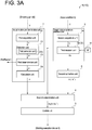
- FIGs. 3A and 3B are each a functional block diagram of the welding control device 1 according to an embodiment of the present invention.
- the welding control device 1 is a device configured to control a position of the position control object 8T which includes at least one of the welding wire 8w used to weld the welding object 9 or the electrode 82 for melting the welding wire 8w.
- the welding control device 1 includes a first decision unit (such as an actual relative position decision unit 2 to be described later) for deciding (acquiring) an actual position of the position control object 8T based on a welding feature amount P detected from the image V which is shot to include at least the position control object 8T, the welding feature amount P including at least one of a wire position Pw of the welding wire 8w or an electrode position Pe of the electrode 82, a second decision unit (such as a target relative position decision unit 3 to be described later) for deciding a target position which is a target of the above-described actual position according to an input condition C based on the input condition C which includes at least one of attitude information Ce of the electrode 82 when the welding object 9 is welded or shape information Cs of the welding
- the attitude information Ce of the electrode 82 is information on the attitude of the electrode 82, and includes at least one kind of attitude control parameter described above. Further, the shape information Cs of the welding object 9 (welded portion) is information on the shape of the welding object 9 such as the welded portion, and may include a groove width L of the groove 91, for example.
- the actual position of the position control object 8T described above is the actual position detected from the image V, and the actual position may be, for example, a position (absolute position) in a coordinate system set in the image V, or may be a relative position (actual relative position Rr) of the wire position Pw, the electrode position Pe, which is the position of the position control object 8T, from the another welding feature amount P (such as a molten pool position Pm, a groove position Pb to be described later).
- the actual relative position Rr may be a distance along a direction to control the position control object 8T.
- the actual relative position Rr may be a position (coordinate) with reference to an optional position such as a lower left end of the image V, or the other position (coordinate) with reference to one of the two welding feature amounts P constituting the actual relative position Rr.
- the position of the welding feature amount P is the absolute position
- control is performed such that the absolute position such as the wire position Pw sets a middle position of the image V in the right-left direction (to be described later) as the target position, in a state where, for example, a camera shooting the image V is fixed so a shooting direction is not changed by the attitude of the electrode 82.
- a function capable of calculating a target absolute position corresponding to the above-described target position from the absolute position or the another welding feature amount P is prepared in advance, and the target absolute position may be obtained from the welding feature amount P by using such function. More specifically, for example, the target absolute position is obtained from a position in the right-left direction (to be described later) of the electrode position Pe and the groove position Pb, by using a non-linear function, a table, or the like.
- FIGs. 3A and 3B are the embodiments where the position of the welding feature amount P is the relative position.
- the embodiment of a case where the actual position of the position control object 8T is the absolute position can be considered by reading, in the following description, the actual relative position Rr as the absolute position and a target relative position Rt as a target absolute position.
- the welding control device 1 includes the actual relative position decision unit (above-described first decision unit), the target relative position decision unit 3 (above-described second decision unit), and the control unit 5.
- the welding control device 1 is constituted by a computer, and includes a CPU (processor; not shown) and a storage device m serving as, for example, an external storage device or a memory such as a ROM or a RAM. Then, the CPU performs an operation (such as computation of data) in accordance with an instruction of a program (welding control program 10) loaded to a memory (main storage device), thereby implementing the above-described functional units of the welding control device 1.
- the above-described welding control program 10 is software for causing the computer to implement the respective functional units to be described later, and may be stored in a computer-readable storage medium.
- the actual relative position decision unit 2 decides the actual relative position Rr which is the relative position of any two of the welding feature amounts P detected from the image V described above, the welding feature amounts P including at least two of the groove position Pb of the groove 91, the wire position Pw of the welding wire 8w, the molten pool position Pm of the molten pool 8m, or the electrode position Pe of the electrode 82.
- the image V is shot to include the position control object 8T and at least one of the groove 91 of the welding object 9 or the molten pool 8m formed in the groove 91 by melting the welding wire 8w.
- the image V may include at least a portion of the wire position Pw of the welding wire 8w, at least a portion of the molten pool position Pm of the molten pool 8m, or at least a portion of the groove position Pb of the groove 91.
- the image V may include at least a portion of the electrode position Pe of the electrode 82 and at least a portion of the groove position Pb of the groove 91.
- the above-described wire position Pw is a position of a desired section in the welding wire 8w.
- the molten pool position Pm is a desired section in the molten pool 8m.
- the groove position Pb is a position of a desired section in the groove 91.
- the electrode position Pe is a position of a desired section in the electrode 82.
- the wire position Pw is a position of the tip portion of the welding wire 8w located on a rearmost side (lowest side in the up-down direction) in the image V.
- the molten pool position Pm is a position of a tip portion of the molten pool 8m located on a foremost side in the image V.
- the groove position Pb is a position of a predetermined portion determined by a relative position to the electrode 82.
- the electrode position Pe is a tip portion of the electrode 82 located on the rearmost side (lowest side in the up-down direction) in the image V.
- the welding feature amounts P include at least the wire position Pw and the molten pool position Pm.
- the actual relative position decision unit 2 performs image processing on the image V, thereby detecting the welding feature amount P and calculating the actual relative position Rr based on the detection result.
- the position control object 8T is the welding wire 8w
- the wire position Pw and the molten pool position Pm are detected.
- the wire position Pw and the groove position Pb are detected.
- the position control object 8T is the electrode 82
- the electrode position Pe and the groove position Pb are detected.
- the position control object 8T is at least the welding wire 8w.
- the actual relative position decision unit 2 includes a first acquisition unit 21 for acquiring the image V from the shooting part 83 for shooting the welded section in welding, a detection unit 22 for detecting the welding feature amount P from the (one or a plurality of) image V acquired by the first acquisition unit 21 for each predetermined control cycle T, and a calculation unit 24 for calculating the actual relative position Rr based on the detected welding feature amount P.
- the above-described first acquisition unit 21 is connected to the shooting part 83, thereby receiving the images V sequentially (in real time). Further, the detection unit 22 is connected to the first acquisition unit 21, thereby sequentially receiving the images V acquired by the first acquisition unit 21.
- the first acquisition unit 21 may store all the input images V in the storage device m, or may store some of the input images V in the storage device m by, for example, decimating the images V at predetermined intervals or the like.
- the images V stored by the first acquisition unit 21 are input to the detection unit 22.
- the detection unit 22 detects the welding feature amount P for each predetermined control cycle T.
- the calculation unit 24 is connected to the detection unit 22, thereby sequentially receiving the welding feature amounts P.
- the target relative position decision unit 3 decides the target relative position Rt which is the target of the above-described relative position (the actual relative position Rr such as the electrode groove relative position, a wire pool relative position) according to the input condition C when the welding object 9 is welded.
- the target relative position Rt needs to be comparable with the above-described actual relative position Rr.
- the target relative position Rt may be decided by applying machine learning, and a decision method therefor will be described later.
- the input condition C is a condition influencing a welding state of the welding object 9 by the welding execution device 8, and includes at least one of the attitude information Ce of the electrode 82 or the shape information Cs of the welding object 9.
- the input condition C is configured such that, for example, the attitude of the electrode 82 is changed to mainly avoid interference with an obstacle in welding or appropriately form the molten pool 8m if the weld line (groove 91) is inclined with respect to the up-down direction. If the attitude of the electrode 82 is changed, the positional relationship between the groove 91 and a discharge direction of arc from the electrode 82 can accordingly be changed regardless of the presence or absence of a change in wire position Pw, and thus the shape of the molten pool 8m can be changed. Then, if the molten pool position Pm is changed in accordance with the change in shape of the molten pool 8m, the target relative position Rt can also be changed. In fact, as shown in FIG. 4 , 5 to be described later, the present inventors have found that the target relative position Rt is changed in accordance with the input condition C.
- the control unit 5 performs position control of the position control object 8T for setting the actual relative position Rr decided by the actual relative position decision unit 2 described above to the target relative position Rt decided by the target relative position decision unit 3 described above.
- the position control of the position control object 8T calculates a control amount of the position control object 8T which is needed for a difference (shift amount) between the actual relative position Rr and the target relative position Rt to fall within a predetermined range including zero, and transmits the calculated control amount to the welding execution device 8. Then, the welding execution device 8 controls the position of the position control object 8T in accordance with the received control amount.
- control amount may be a movement amount from a current position to a direction in which the position control object 8T should move, or may be a coordinate to which the position control object 8T should move in a coordinate system where the welding execution device 8 recognizes the position.
- control unit 5 may control, through the image processing on the image V, the position of the position control object 8T while detecting a position obtained after moving relative to the transmitted control amount (feedback control).
- At least one of the electrode 82 or the wire position Pw may be controlled in the front-rear direction or the like such that the actual relative position Rr of the electrode position Pe to the wire position Pw becomes the target relative position Rt.
- the electrode 82 may be controlled in the right-left direction or the like such that the actual relative position Rr of the electrode position Pe to the groove position Pb becomes the target relative position Rt.
- the actual relative position Rr (wire pool relative position) may be calculated based on the welding feature amounts P including the detected wire position Pw and molten pool position Pm.
- the relative position may be a relative position (wire pool relative position) of the wire position Pw to the molten pool position Pm along the front-rear direction, or may be a relative position of the wire position Pw to the molten pool position Pm along the right-left direction.
- the electrode position Pe may be the tip portion of the electrode 82 located on the foremost side in the front-rear direction, and the groove position Pb may be a position of a predetermined section determined by the relative position to the electrode 82. At least one of the welding wire 8w or the electrode 82 may be controlled such that the actual relative position Rr of the electrode position Pe to the wire position Pw becomes the target relative position Rt.
- the welding control device 1 decides the target position (target relative position Rt) of the position control object 8T, such as the welding wire 8w or the electrode 82, in accordance with the input condition C including the attitude information Ce of the electrode 82 or the shape information Cs (such as the groove width) of the welding object 9. Then, the welding control device 1 controls the welding execution device 8 such that the actual position (actual relative position Rr) of the position control object 8T which is obtained through the image processing on the image V shot during welding coincides with the target position.
- the welding control device 1 controls the welding execution device 8 such that the actual position (actual relative position Rr) of the position control object 8T which is obtained through the image processing on the image V shot during welding coincides with the target position.
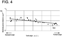
- FIG. 4 is a graph showing a correlation between the target relative position Rt and the attitude information Ce of the electrode 82 according to an embodiment of the present invention.
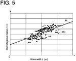
- FIG. 5 is a graph showing a correlation between the target relative position Rt and the shape information Cs of the welding object 9 according to an embodiment of the present invention.
- FIG. 6 is a view for describing an estimation method for the groove width L in weaving welding according to an embodiment of the present invention.
- the actual relative position Rr and the target relative position Rt described above may be the relative position of the wire position Pw to the molten pool position Pm, or may be the relative position of the electrode position Pe to the groove position Pb.
- the present invention is not limited thereto, but the actual relative position Rr and the target relative position Rt may be the relative position of any two of the above-described welding feature amounts P (the wire position Pw, the molten pool position Pm, the electrode position Pe, the groove position Pb).
- the above-described target relative position decision unit 3 includes a second acquisition unit 3a for acquiring at least some of the input conditions C when the welding object 9 is welded, and a third decision unit 3b for deciding the target relative position Rt (target position; the same applies hereafter) according to the input conditions C acquired by the second acquisition unit 3a from the input conditions C, based on the relationship between an input condition in previous welding (previous input condition) and a previous relative position (previous position; the same applies hereafter) which is the relative position of the any two of the welding feature amounts P described above, such as a relative position of the previous molten pool position Pm (previous molten pool position) to the previous wire position Pw (previous wire position) or a relative position of the previous electrode position Pe (previous electrode position) to the previous groove position Pb, set under the previous input condition.
- the above-described relationship is derived by, in the previous welding procedure, accumulating information on how the welder sets the relative position of the any two of the welding feature amounts P, such as the position of the electrode position Pe relative to the groove position Pb, the wire position Pw relative to the molten pool position Pm, and the wire position Pw relative to the electrode position Pe, in association with a record of information on contents of the input condition C at that time, and learning (machine learning) the above as learning data.
- the above-described third decision unit 3b may decide the target relative position Rt according to the input condition C during welding, by using a learning model M which is obtained by machine learning of a plurality of data associating the above-described previous input condition with the previous relative position set under the previous input condition.
- the above-described plurality of data are obtained by acquiring, for example, a plurality of times at different times, an information set of the input condition C and the previous relative position calculated based on the welding feature amounts P at the same timing.
- the plurality of data may include information on a time, a place, and a time of welding procedure for the different welding objects 9. Then, with the thus obtained plurality of data associating the previous relative position at each of a plurality of timings with the input condition C being learning data Md, machine learning is performed.
- the target relative position decision unit 3 can decide the target relative position Rt corresponding to the acquired input condition C.
- the present inventors have found that there is a correlation between the target relative position Rt and the attitude information Ce of the electrode 82, through an intensive analysis of welding data when a skilled welder operates the welding execution device 8. More specifically, for example, as shown in FIG. 4 , the skilled welder operates the electrode 82 such that a distance (ordinate) between the electrode 82 and the groove 91 (to be referred to as an electrode ⁇ groove distance, hereinafter) decreases as a torch angle ⁇ t (abscissa) increases (the forward angle increases, or the backward angle decreases), finding the correlation between the torch angle ⁇ t and the electrode ⁇ groove distance.
- the learning model M (function) capable of obtaining the electrode ⁇ groove distance from the torch angle ⁇ t is obtained. Then, the learning model M is stored in the storage device m, allowing the target relative position decision unit 3 to calculate the target relative position Rt on the basis of the torch angle ⁇ t by using the learning model M.
- the present inventors have found, from the above-described welding data, that there is a correlation between the target relative position Rt and the shape information Cs of the welding object 9. More specifically, for example, as shown in FIG. 5 , the skilled welder operates the electrode 82 such that the electrode ⁇ groove distance (ordinate) increases as the groove width L (abscissa) increases, finding the correlation between the groove width L and the electrode ⁇ groove distance. Thus, obtaining the relationship as indicated by a regression line of FIG.
- the learning model M (function) capable of obtaining the electrode ⁇ groove distance from the groove width L (shape information Cs) is obtained. Then, the learning model M is stored in the storage device m, allowing the target relative position decision unit 3 to calculate the target relative position Rt on the basis of the groove width L by using the learning model M.
- the learning model M is stored in the storage device m, allowing the target relative position decision unit 3 to calculate the target relative position Rt on the basis of the groove width L by using the learning model M.
- the electrode ⁇ groove distance (ordinate) of FIG. 5 is a distance (left distance Ll; see FIG. 6 ) between the electrode 82 and the groove 91 (left groove position) reflected on the left side of the image V.
- a plurality of passes are welded in the right-left direction, and are welded to be laminated in the up-down direction. Further, weaving welding where welding is executed while swinging the electrode in the right-left direction addresses a case where welding of a right pass is executed.
- the shape of the welding object 9 may constantly change during welding.
- the above-described target relative position decision unit 3 may estimate the above-described groove width L based on the image V and a weaving width Lw of the electrode 82, and may decide the target relative position Rt of the electrode 82 based on the estimated groove width L.
- a distance (right distance Lr) between the electrode 82 and the groove 91 (right groove position) reflected on the right side of the image V is acquired based on the image V when the rightmost groove 91 is approached.
- the distance (left distance LI) between the electrode 82 and the groove 91 (left groove position) reflected on the left side of the image V is acquired based on the image V when the leftmost groove 91 is approached. That is, if the electrode 82 moves once between the left groove 91 and the right groove 91 by one weaving operation, the right distance Lr and the left distance Ll are obtained.
- the weaving width Lw is a value obtained when the welding execution device 8 is controlled.
- the weaving width L corresponding to the following one weaving operation has a value generally close to a calculated value obtained as described above, if the groove width L slowly changes along the welding direction.
- setting the calculated value as an estimated value of the groove width L of a section where welding is to be executed it is possible to appropriately decide the target relative position Rt based on the estimated value of the groove width L.
- learning for example, machine learning
- the target position such as the target relative position Rt
- FIG. 7 is a view for describing a correction method on the basis of the roll angle ⁇ r of the groove position Pb according to an embodiment of the present invention.
- the welder moves the position control object for a determined target position while seeing one of the portions such as the welding wire, the electrode, the molten pool, or the groove represented in the image. Then, if the target position is obtained from the relationship between the input condition and the portion seen by the welder, it is considered possible to bring the welding quality of automatic arc welding closer to that of the welder. For example, if the welding feature amount (such as the groove position) to be detected from the image that increases the correlation between the input condition and the target position such as the target relative position is known through analysis of the welding data, the position of the welding feature amount obtained as the result of image processing may deviate from an appropriate position which is supposed to be detected.
- the welding feature amount such as the groove position
- the shooting direction to shoot the welding object 9 may be changed in accordance with attitude control of the electrode 82.
- the change in attitude changes the way the shooting object such as the position control object 8T or the welding object 9 represented in the image V is reflected (seen).
- the welding feature amount P such as the groove position Pb of the groove 91 obtained as the result of image processing may deviate from the appropriate position which is supposed to be detected.
- the target relative position Rt (target position) decided based on the welding feature amount P where the above-described deviation is caused has low correlation with respect to the input condition C. If such target relative position Rt is used for control, accuracy of position control of the position control object 8T such as the electrode 82 may be decreased.
- the welding feature amount P may be corrected based on the attitude information Ce of the electrode 82, and the actual relative position Rr of the position control object 8T may be decided based on the corrected welding feature amount P.
- the image V is shot to include at least the position control object 8T and the groove 91 of the welding object 9.
- the welding feature amount P includes at least the wire position Pw or the electrode position Pe and the groove position Pb.
- the shooting part 83 for shooting the image V is installed such that the shooting direction to shoot the welding object 9 is set in accordance with the attitude of the electrode 82.
- the shooting part 83 is fixed to the attitude control mechanism 82c to shoot the vicinity of the tip of the electrode 82, and thus the direction of the tip portion of the electrode 82 with respect to the groove 91 changes if the attitude of the electrode 82 changes. Accordingly, the shooting direction of the groove 91 shot together with the electrode 82 changes.
- the above-described actual relative position decision unit 2 corrects the groove position Pb based on the attitude information Ce of the electrode 82, and decides the actual relative position Rr (actual position) based on the welding feature amount P including the corrected groove position Pb (corrected groove position Pb').
- the actual relative position decision unit 2 may further include a first correction unit 22c configured to correct the groove position Pb based on the attitude information Ce of the electrode 82.
- the first correction unit 22c is provided to be included in the detection unit 22.
- a method for correcting the groove position Pb will be described with reference to FIG. 7 .
- the electrode 82 is applied with the roll angle ⁇ r other than 0°, and the shooting part 83 also rotates by the roll angle ⁇ r with respect to the groove 91 by rotating together with the electrode 82.
- the groove 91 is shot in a state where the groove 91 is inclined with respect to the welding direction by the angle ⁇ r.
- performing image processing on the image V a position in the vicinity of just beside the welding wire 8w is detected as the groove position Pb.
- the groove position Pb detected from the image V depends on a shooting condition such as brightness in shooting, and thus one of portions of the groove 91 is detected as a result of processing according to an algorithm of image processing.
- the portion of the groove 91 (the position of Pb') located just beside the electrode 82 as the groove position Pb is more desirable as the groove position Pb to be detected.
- the position desirable as the groove position Pb is, for example, the position which is found, from analysis of the welding data, to have high correlation between the target relative position Rt and the input condition C.
- the electrode ⁇ groove distance is obtained by detecting the electrode position Pe and the groove position Pb, but a difference in level of correlation (correlation coefficient) is caused depending on which position is detected from the image V as the electrode position Pe.
- the position desirable as the groove position Pb is the groove position Pb where the correlation between the torch angle ⁇ t and the electrode ⁇ groove distance is the highest.
- the shooting direction to shoot the welding object 9 by the shooting part 83 for shooting the image V is set in accordance with the attitude of the electrode 82, the welding feature amount P such as the groove position Pb serving as the welding feature amount P is corrected based on the attitude information Ce of the electrode 82.
- the welding feature amount P such as the groove position Pb serving as the welding feature amount P is corrected based on the attitude information Ce of the electrode 82.
- the above-described input condition C may further include the welding condition Cw when the welding object 9 is welded.
- the welding condition Cw is a condition influencing a welded state of the welding object 9 by the welding execution device 8, and is a condition for directly adjusting (controlling) a heat input condition. That is, if the welding condition Cw changes, the heat input condition (heat input state) in welding changes.
- the welding condition Cw may include at least one condition of an electrode current or an electrode voltage with respect to the electrode 82, a welding speed which is a speed of relative movement of the welding execution device 8 to the welding object 9 (movement speed of arc), a supply amount (supply amount per unit time) of the welding wire 8w, or the groove width L of the groove 91.
- the above-described target relative position decision unit 3 may include the second acquisition unit 3a for acquiring the input condition C including at least one of the attitude information Ce of the electrode 82 or the shape information Cs of the welding object 9 (welded portion) and the welding condition Cw, and the above-described third decision unit 3b (condition-based target decision unit 32).
- the condition-based target decision unit 32 decides the target relative position Rt according to the input condition C during welding, by using the learning model M (condition-based learning model) which is obtained by machine learning of the learning data Md associating the previous input condition in previous welding with the previous relative position set under the previous input condition.
- the input condition C includes the welding condition Cw
- at least two conditions of the plurality of conditions may be consolidated to a single condition to reduce the number (dimension) of the conditions included in the input condition C. More specifically, if the welding condition Cw includes a plurality of conditions, at least two conditions of the plurality of conditions may be consolidated to a single condition to reduce the number (dimension) of the conditions included in the welding condition Cw to be an input.
- the welding condition Cw includes the consolidated condition obtained by consolidating the at least two conditions of the welding condition Cw to the single condition, and another condition.
- the target relative position decision unit 3 decides the target relative position Rt according to the welding condition Cw including such consolidated condition, and at least one the attitude information Ce of the electrode 82 or the shape information Cs of the welding object 9 (welded portion).
- a relationship between the previous relative position, and the input condition C with the welding condition Cw including consolidation of three conditions, that is, the welding speed, the welding current, and the welding voltage to one condition, that is, a heat input amount may be learned.
- the learning model M in this case includes the one condition, the heat input amount instead of the three conditions, that is, the welding speed, the welding current, and the welding speed.
- the present invention is not limited to the present embodiment.
- a condition representing the relationship with the target relative position Rt the most can be consolidated.
- the two conditions, that is, the welding speed and the welding current can be consolidated to the one condition, that is, the heat input amount.
- the welding condition Cw includes the plurality of conditions
- a table encompassing a combination of the plurality of conditions is needed.
- the plurality of conditions are consolidated to the single condition to reduce the number of dimensions, it is possible to reduce the cost of creating the table.
- the welding condition Cw when the welding object 9 is welded may acquire a set value set in the welding execution device 8 or the like from the welding execution device 8, or may acquire an input from an operator or the like.
- the target relative position Rt is obtained directly from the welding condition Cw.
- the above-described target relative position decision unit 3 may include the second acquisition unit 3a for acquiring at least one of the attitude information Ce of the electrode 82 or the shape information Cs of the welding object 9 (welded portion) of the condition included in the input condition C, and the third decision unit 3b (position-based target decision unit 34) for deciding the target relative position Rt according to the input condition C from the welding feature amounts P such as the molten pool position Pm and the wire position Pw to be the inputs based on the relationship between previous welding feature amounts (to be referred to as previous welding feature amounts) such as the previous molten pool position and the previous wire position in welding performed under the previous input conditions including at least one of the attitude information Ce of the electrode 82 or the shape information Cs of the welding object 9 (welded portion) and welding condition Cw in the previous welding, and the previous relative position which is a relative position of the previous welding feature amounts.
- the third decision unit 3b position-based target decision unit 34
- the reason for thus configuring the target relative position decision unit 3 is that, as already described, the heat input condition (heat input state) in welding changes if the welding condition Cw changes, and thus the appropriate position of the position control object 8T such as the welding wire 8w or the electrode changes in accordance with the input condition C.
- the welder recognizes, mainly based on visual information on the welded state which varies in accordance with the input condition C, the welding feature amount P (such as the wire position Pw, the molten pool position Pm, the electrode position Pe, or the groove position Pb) for ensuring welding quality, and operates the wire position Pw, the electrode 82, or the like based on his/her experiences, thereby achieving high-quality welding.
- the present inventors consider that the difference by the input condition C is reflected on the operation performed by the welder, and the target relative position Rt can be obtained from an operation history of the welder in place of the input condition C.
- the target relative position decision unit 3 decides the target relative position Rt according to the input condition C from the above-described welding feature amount P and at least one of the attitude information Ce of the electrode 82 or the shape information Cs of the welding object 9, by using the learning model M (position-based learning model) which is obtained by machine learning of the learning data Md associating the above-described previous welding feature amount, at least one of the attitude information Ce of the electrode 82 or the shape information Cs of the welding object 9, and the above-described previous relative position with each other.
- the learning model M position-based learning model
- the position-based learning model may be the learning model M which is obtained by machine learning of the learning data Md associating the above-described previous welding feature amount with the above-described previous relative position.
- the learning data Md in this case can be learned by setting the attitude information Ce of the electrode and the shape information Cs of the welding object 9 as explanatory variables, and the target relative position decision unit 3 can accurately decide the target relative position Rt with respect to the welding object 9.
- the target relative position Rt is obtained from the welding feature amounts P such as the position of the molten pool 8m and the position of the welding wire 8w.
- the target relative position Rt of the welding wire 8w to the molten pool 8m is in a linear relationship
- the input condition C that has not yet been experienced but close to the condition experienced in the past and a condition interpolated in a plurality of data fall into the category of linear modelization, and thus can be addressed.
- the target relative position Rt for position control it is possible to implement the same welding quality as the case where welding is executed by the welder.
- the present invention is not limited to the above-described two embodiments.
- the target relative position Rt according to the input condition C during welding is decided by using the above-described learning model M
- not less than two learning models M may be used for the decision. More specifically, a first learning model for obtaining the target relative position Rt (temporary target relative position) according to the welding condition Cw is created therefrom, and a second learning model for obtaining, from at least one of the attitude information Ce of the electrode 82 or the shape information Cs of the welding object 9 (welded portion), a correction amount of the temporary target relative position according thereto. Then, the final target relative position Rt of the position control object 8T may be decided by correcting the temporary target relative position obtained by the first learning model with the correction amount obtained by the second learning model.
- a target value conversion means such as a function or a table for presetting the target relative position Rt according to the input condition C in consideration of the welding condition Cw (heat input condition) or the like is created, and the target relative position decision unit 3 may decide the target relative position Rt from the input condition C by using the target value conversion means. More specifically, the target relative position decision unit 3 may decide the target relative position Rt from the input condition C by using the target value conversion means for obtaining the target relative position Rt corresponding to the input condition C from the input condition C created by using the above-described condition-based learning model.
- the target relative position decision unit 3 may decide the target relative position Rt from the welding feature amount P by using the target value conversion means for obtaining the target relative position Rt corresponding to the welding feature amount P from the welding feature amount P created by using the above-described position-based learning model.
- the target relative position decision unit 3 may decide the target relative position Rt from the welding feature amount P by using the target value conversion means for obtaining the target relative position Rt corresponding to the welding feature amount P from the welding feature amount P created by using the above-described position-based learning model.
- the input condition C further includes the welding condition Cw in addition to at least one of the attitude information Ce of the electrode 82 or the shape information Cs of the welding object 9 has been described above.
- the above-described embodiments also hold in the case where the input condition C only includes the welding condition Cw.
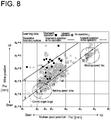
- FIG. 8 is a graph showing a relationship among the molten pool position Pm, the wire position Pw, and the operation history by the welder according to an embodiment of the present invention.
- FIG. 9 is a diagram of a logic when a failure event of welding is detected according to an embodiment of the present invention.
- the welding control device 1 may further include a second determination unit 4 (necessity determination unit) for determining the necessity of position control of the position control object 8T based on the difference between the target relative position Rt and the actual relative position Rr described above, as shown in FIGs. 3A and 3B .
- the above-described control unit 5 performs position control of the position control object 8T such as the welding wire 8w in accordance with a determination result by the second determination unit 4.
- FIG. 8 shows the operation performed by the welder in the combination of the molten pool position Pm and the wire position Pw. More specifically, a point plotted by a black square indicates that the welder performs an operation downward (downward operation), a point plotted by a light-colored square indicates that the welder performs an operation upward (upward operation), and a point plotted by a white circle indicates that the welder performs no operation.
- the molten pool position Pm and the wire position Pw of the graph shown in FIG. 8 are a relative position from an origin at the lower left end of the image V (see FIG. 2 ).
- the present invention is not limited to the present embodiment, and the origin of the coordinate can be an optional position.
- a value of the ordinate is larger than a value of the abscissa by a constant S
- a dashed line is a line connecting points at which the wire position Pw is larger than the molten pool position Pm by the constant S.
- the dashed line for example, it can be seen that the position of the molten pool position Pm and the position the wire position Pw are different in accordance with whether the welding speed is fast or slow.
- the wire pool relative position distance
- the wire position Pw at the plot points (white circles) indicating no operation are concentrated below the dashed line, and the actual relative position Rr is shorter.
- the welder performs the operation and the case where the welder does not perform the operation. Then, a tendency can be seen from FIG. 8 that at the molten pool position Pm, the welder does not perform the operation in a certain range of the wire position Pw, performs the downward operation if the wire position Pw increases over the range, and performs the upward operation if the wire position Pw goes below the range.
- the second determination unit 4 does not perform position control of the welding wire 8w (a control dead zone is set) even if the difference is caused between the target relative position Rt and the actual relative position Rr.
- a control dead zone is set
- the above-described predetermined range may be set based on a plurality of operation history data which associates the previous welding feature amount with the presence or absence of the operation of the position control object 8T corresponding thereto, such as a plurality of operation history data which associates the previous molten pool position, the previous wire position, and the presence or absence of the operation of the previous wire position at that time in the previous welding with each other.
- the second determination unit 4 determines that position control of the position control object 8T such as the welding wire 8w is necessary, if the difference between the actual relative position Rr and the target relative position Rt described above deviates from the control dead zone (predetermined range) set as described above. Conversely, the second determination unit 4 determines that position control of the position control object 8T is unnecessary, if the above-described difference falls within the range of the control dead zone.
- a classification model having the welding feature amount P as an input and a label for the presence or absence of the operation as an output is generated by a support vector machine (SVM), and regarding a feature amount space to be focused (a two-dimensional space of the molten pool position Pm and the wire position Pw in FIG. 8 ), a separation boundary surface between a space where an intervention operation by an operator is necessary (label: operation present) and a space where the operation is unnecessary (label: operation absent) is specified.
- the thus obtained lines are a solid line and a double-dotted chain line shown in FIG. 8 .
- the solid line is a separation boundary between the presence of the downward operation and the absence of the operation, and the downward operation is present in a space above the solid line and is absent in a space below the solid line.
- the double-dotted chain line is a separation boundary between the presence of the upward operation and the absence of the operation, the upward operation is present in the space above the solid line, and the downward operation is absent in the space below the solid line. Then, a space between these two separation boundaries is the control dead zone where the operation is unnecessary.
- the downward operation is performed if the wire position Pw relative to the molten pool position Pm is above the solid line
- the upward operation is performed if the wire position Pw relative to the molten pool position Pm is below the double-dotted chain line
- no operation is performed if the wire position Pw relative to the molten pool position Pm is between the solid line and the double-dotted chain line.
- the range between the solid line and the double-dotted chain line described above in each molten pool position Pm is the control dead zone
- the control dead zone is a control target range of the wire position Pw.
- the target relative position Rt calculated by the target relative position decision unit 3 falls within the control target range.
- the second determination unit 4 is connected to the actual relative position decision unit 2 and the target relative position decision unit 3, receives the actual relative position Rr and the target relative position Rt, and receives the actual relative position Rr and the target relative position Rt from the actual relative position decision unit 2. Further, receiving the actual relative position Rr and the target relative position Rt, the second determination unit 4 does not perform position control of the wire position Pw even if there is the difference between the target relative position Rt and the actual relative position Rr, as long as the difference between the actual relative position Rr and the target relative position Rt is in the range of the control dead zone. Conversely, if the difference between the actual relative position Rr and the target relative position Rt deviates from the range of the control dead zone, the second determination unit 4 performs position control of the wire position Pw such that the difference falls within the range of the control dead zone.
- the collected operation history data (learning data) has a small amount of data on the presence of the operation (such as the presence of the downward operation, the presence of the upward operation) relative to the absence of the operation. If there is such imbalance in the number of data, it is known that identification performance of SVM decreases greatly. Thus, in order to eliminate imbalance in the number of data, in the embodiment shown in FIG. 8 , by performing class weighting based on the ratio of the number of data, a problem is resolved that a class where the operation is present which is small in the number of data is underevaluated.
- the range for determining the necessity of execution of the position control of the welding wire 8w is decided based on the relationship between the presence or absence of the operation at the position of the welding wire 8w performed by the welder, and the previous molten pool position and the wire position.
- the above-described predetermined range may be decided in accordance with the input condition C such as the welding condition Cw. That is, the control dead zone for determining the necessity of execution of position control of the welding wire 8w is variable in accordance with the input condition C or the welding feature amounts P such as the molten pool position Pm and the wire position Pw on which the input condition C is reflected.
- the above-described predetermined range (the range of the control dead zone) in accordance with the input condition C, and to appropriately address each of the input condition C where position control of the welding feature amount P such as the welding wire 8w needs to be performed strictly and the input condition C where the above-described position control need not be performed strictly.
- the above-described predetermined range may be constant regardless of the input condition C.
- the above-described actual relative position decision unit 2 may further include the first determination unit 23 (abnormality determination unit) for determining a detected abnormality in the welding feature amount P for each control cycle T described above by the detection unit 22 (to simply be referred to as a detected abnormality, hereinafter), as shown in FIGs. 3A and 3B . More specifically, in the normal control cycle Ts which is the control cycle T determined by the first determination unit 23 that the detected abnormality does not occur, the actual relative position decision unit 2 calculates the actual relative position Rr based on the welding feature amount P which is detected from the image V acquired in the normal control cycle Ts.
- the first determination unit 23 abnormality determination unit
- the actual relative position decision unit 2 may calculate the actual relative position Rr based on the welding feature amount P which is detected from the image V acquired in the normal control cycle Ts which has already been terminated before the abnormal control cycle Tf. That is, in the abnormal control cycle Tf, the actual relative position decision unit 2 may use the actual relative position Rr obtained in the normal control cycle Ts before the abnormal control cycle Tf.
- the above-described detected abnormality is a case of an outlier such as a case where the welding feature amount P cannot be detected from the image V at all for each control cycle T through image processing by the detection unit 22, a case where the value of the welding feature amount P is unexpectedly and greatly changed from the prior value, or a case where the value of the welding feature amount P becomes a value which is impossible under normal circumferences.
- the welding feature amount P cannot appropriately be detected, such as the welding feature amount P cannot be detected or is erroneously detected by image processing, due to the fact that the image V becomes too dark if the heat input amount set by the welding condition Cw is too small and conversely, the image V becomes too bright if the heat input amount is too large, for example.
- the abnormal control cycle Tf it may be configured such that the welding feature amount P which is detected from the image V acquired in the normal control cycle Ts before the abnormal control cycle Tf is input to the calculation unit 24, or the actual relative position Rr from the image V acquired in the normal control cycle Ts before the abnormal control cycle Tf is output from the calculation unit 24.
- the first determination unit 23 determines the presence or absence of the detected abnormality based on a notification that the welding feature amount P input from the detection unit 22 cannot be detected or the value of the welding feature amount P. Then, the welding feature amount P input from the detection unit 22 is output to the calculation unit 24, if the first determination unit 23 determines that there is no detected abnormality.
- FIG. 10 is a view for describing an operation of the actual relative position decision unit 2 in the abnormal control cycle Tf according to an embodiment of the present invention and shows a case where the normal control cycle Ts exists by a predetermined period R before in the abnormal control cycle Tf.
- FIG. 10 shows a state where each control cycle T is repeated with time, and the welding feature amount P (PI, P2, ..., Pn-1, Pn+1, ...: n is an integer) is detected from the image V acquired in each control cycle T.
- the control cycles T before and after the nth control cycle are the normal control cycles Ts, and the nth control cycle is the abnormal control cycle Tf.
- the actual relative position decision unit 2 detection unit 22
- the actual relative position decision unit 2 uses the welding feature amount P detected from the image V in the normal control cycle Ts before (previous to) the nth abnormal control cycle Tf as a substitute for the welding feature amount P detected from the image V in the nth abnormal control cycle Tf.
- the actual relative position decision unit 2 may be configured not to decide the actual relative position Rr in the abnormal control cycle Tf.
- the notification may be made if a period until the first normal control cycle Ts after the abnormal control cycle Tf exceeds the predetermined period R.
- the first determination unit 23 may make a notification to be described later.
- the welding feature amount P in the (n-2)th normal control cycle Ts may be substituted.
- the welding feature amount P in the (n-1)th (immediately preceding) normal control cycle Ts is substituted in FIG. 10
- the welding feature amount P can be the welding feature amount P in the normal control cycle Ts included in the above-described predetermined period R.
- the first acquisition unit 21 acquires the plurality of images V, and the acquired images V are accumulated in the storage device m or the like. Then, the detection unit 22 detects the welding feature amount P from the plurality of images V accumulated for each control cycle T, and if the welding feature amount P of interest cannot be detected from the plurality of images V at all (there is no valid data), it is determined that the above-described detected abnormality occurs. Thus, a processing load by performing a process for position control for each image is reduced while appropriately performing position control of the position control object 8T.
- a value which is considered the most appropriate as the reference of control for example, a value detected from the image V which is the latest in one cycle of the normal control cycle Ts among the images V where the position is detected appropriately may be used, as the welding feature amount P, for subsequent calculation of the actual relative position Rr.
- the present invention is not limited to the embodiments shown in FIGs. 1A to 3B and in some other embodiments, the first acquisition unit 21 may acquire one image V during one cycle of the above-described control cycle T. In this case, if the detection unit 22 cannot detect the welding feature amount P of interest from the one image V obtained for each control cycle T, it is determined that the above-described detected abnormality is determined.
- the actual relative position Rr on the basis of the image V determined that the detected abnormality does not occur is used by, for example, calculating the actual relative position Rr by using, as a substitute, the welding feature amount P (substitute feature amount) which is detected from the image V acquired in the immediately preceding normal control cycle Ts or the like.
- the welding feature amount P substitute feature amount
- the actual relative position decision unit 2 may be configured not to control the position control object 8T, for example, by not outputting the actual relative position Rr to the calculation unit 24 in the abnormal control cycle Tf. That is, in the abnormal control cycle Tf, by continuing the welding procedure without controlling the position control object 8T based on the actual relative position Rr and the target relative position Rt of the position control object 8T, natural recovery of the detected abnormality in the welding feature amount P may simply be waited. Then, a notification may be made in a case where the normal control cycle Ts is not obtained even if the predetermined period R passes.
- the above-described first determination unit 23 makes a notification if the period until the first normal control cycle Ts after the abnormal control cycle Tf exceeds the predetermined period R which is set in accordance with the position control object 8T such as the welding wire 8w (see FIG. 11 ). That is, the first determination unit 23 makes the notification that it is necessary to determine whether welding is continuable, if the detected abnormality in the welding feature amount P from the image V is continued over the predetermined period R. The notification gives notice of the detected abnormality in the welding feature amount P.
- the notification may be directed to the operator or the like, may be an output of an abnormality notification message to a display or the like, or may be a notification by sound or voice.
- the first determination unit 23 may automatically transmit an instruction to stop welding to the welding execution device 8, together with the notification.
- FIG. 11 is a view for describing the operation of the actual relative position decision unit 2 in the abnormal control cycle Tf according to an embodiment of the present invention and shows a case where the normal control cycle Ts does not exist by the predetermined period R before in the abnormal control cycle Tf.
- the (Pn-1)th control cycle T is the normal control cycles Ts
- the control cycles T thereafter are the abnormal control cycles Tf.
- the actual relative position decision unit 2 detection unit 22
- the first determination unit 23 makes the above-described notification after the end of the (n+m-1)th control cycle T.
- the first determination unit 23 may transmit the instruction to stop welding described above, together with the notification.
- the welding feature amount P in the previous normal control cycle Ts may be substituted, as described above.
- the above-described predetermined period R is a period capable of continuing welding without control, and the notification is made after a lapse of the period. Thereby, it is possible to improve reliability of welding while continuing welding as much as possible.
- the shape of the groove (the wall of the welding object 9) rarely changes rapidly, and thus the electrode 82 has a relatively long period during which welding is likely to be continuable without control
- the position of the welding wire 8w which is wound by the reel and is used while being drawn out, may change rapidly, easily changes from the position in the image V immediately before detected abnormality, and thus has a relatively short period during which welding is likely to be continuable without control.
- setting the above-described predetermined period R in accordance with the welding feature amount P it is possible to continue welding which is suitable when abnormalities are detected in various feature amounts included in the welding feature amounts P.
- the welding control device 1 may further include a second correction unit 6 for correcting the target relative position Rt decided by the target relative position decision unit 3, if a failure event of welding is detected.
- the target relative position Rt is corrected by a target position correction amount Rc which is output when the second correction unit 6 detects the failure event of welding. If the second correction unit 6 corrects the target relative position Rt, the corrected target relative position Rt' and the actual relative position Rr are input to the second determination unit 4.
- the above-described failure event of welding is an event of, for example, a droplet which is generated when the tip of the welding wire 8w is not in the molten pool 8m, or poking in which the tip of the welding wire 8w hits the welding object 9 which is the bottom of the molten pool 8m.
- the droplet is a ball-shaped metal of liquid phase obtained by melting the welding wire 8w which falls into the molten pool 8m due to the fact that the tip of the welding wire 8w floats upward because of a warping habit or the like thereof and the tip of the welding wire 8w is melted by arc heat in a state where the tip of the welding wire 8w is not inserted into the molten pool 8m.
- the welding wire 8w floats above the molten pool 8m. If the tip of the welding wire 8w floats above the molten pool 8m because of the warping habit or the like thereof, the welding wire 8w is not completely melted and may collide with the electrode 82. If the welding wire 8w collides with the electrode 82, the electrode 82 and the welding wire 8w are short-circuited, which may interrupt arc discharge or may break the electrode 82.
- control hunting may be caused as a result of performing control in an opposite direction to each other, such as one performs downward control and the other performs upward control.
- FIG. 12 is a flowchart of a welding control method according to an embodiment of the present invention.
- the welding control method is a method for controlling the position of the position control object 8T which includes at least one of the welding wire 8w used to weld the welding object 9 or the electrode 82 for melting the welding wire 8w.
- the welding control method includes a step (S1) of deciding the actual relative position Rr, a step (S2) of deciding the target relative position Rt, and a step (S4) of controlling the position of the position control object 8T.
- the welding control method may include a step (S3) of determining the necessity of position control of the position control object 8T.
- the welding control method will be described in order of steps with reference to FIG. 12 .
- the flow of FIG. 12 is repeated, for example, periodically in the welding procedure.
- step S1 of FIG. 12 the above-described actual relative position Rr is decided based on the image V.
- Step S1 is the same as the processing contents performed by the actual relative position decision unit 2 (first decision unit) that have already been described, and thus details of which are to be omitted.
- step S11 includes acquiring the image V from the shooting part 83 described above
- step S12 includes detecting the above-described welding feature amount P from the image V
- step S13 includes calculating the above-described actual relative position Rr based on the welding feature amount P.
- the welding control method may further include a step (S12a) of determining a detected abnormality in the welding feature amount P by step S12 described above.
- Step S14 is the same as the processing contents performed by the first determination unit 23 that have already been described, and thus details of which are to be omitted.
- step S12a following step S12 includes determining the detected abnormality, and if it is determined that there is no detected abnormality, step S13 is performed. Conversely, if it is determined in step S12a that there is the detected abnormality, step S12b includes automatically transmitting an instruction to stop welding to the welding execution device 8.
- Step S2 includes deciding the target relative position Rt.
- Step S2 is the same as the processing contents performed by the target relative position decision unit 3 (second decision unit) that have already been described, and thus details of which are to be omitted.
- the target relative position Rt is decided based on the learning model M created by the above-described machine learning method.
- Step S3 includes determining the necessity of position control of the position control object 8T based on the difference between the target relative position Rt and the actual relative position Rr. Step S3 is the same as the processing contents performed by the second determination unit 4 that have already been described, and thus details of which are to be omitted.
- step S31 includes determining whether the difference between the target relative position Rt and the actual relative position Rr deviates from the above-described control dead zone, and if it is determined that the above-described difference deviates from the control dead zone, position control of the position control object 8T is determined as necessary, advancing the flow to next step S4. Conversely, if it is determined in step S31 that the difference between the target relative position Rt and the actual relative position Rr does not deviate from the control dead zone, position control of the position control object 8T is determined as unnecessary, terminating the flow.
- Step S4 includes performing position control of the position control object 8T, and setting the actual relative position Rr of the position control object 8T decided in step S1 to the target relative position Rt decided in step S2.
- Step S4 is the same as the processing contents performed by the control unit 5 that have already been described, and thus details of which are to be omitted.
- the above-described welding control method may further include a step of correcting the target relative position Rt decided by the step (S2) of deciding the target relative position Rt described above, if the failure event of welding is detected.
- the above-described step is the same as the processing contents performed by the second correction unit 6 that have already been described, and thus details of which are to be omitted.
- the step of correcting the target relative position Rt is preferably performed between step S2 and step S3 of FIG. 12 (see FIG. 9 ).
- the present invention is not limited to the above-described embodiments, and also includes an embodiment obtained by modifying the above-described embodiments and an embodiment obtained by combining these embodiments as appropriate.
Landscapes
- Engineering & Computer Science (AREA)
- Physics & Mathematics (AREA)
- Mechanical Engineering (AREA)
- Plasma & Fusion (AREA)
- Theoretical Computer Science (AREA)
- Software Systems (AREA)
- Computer Vision & Pattern Recognition (AREA)
- General Physics & Mathematics (AREA)
- Artificial Intelligence (AREA)
- Evolutionary Computation (AREA)
- Data Mining & Analysis (AREA)
- Medical Informatics (AREA)
- Computing Systems (AREA)
- General Engineering & Computer Science (AREA)
- Mathematical Physics (AREA)
- Butt Welding And Welding Of Specific Article (AREA)
- Arc Welding Control (AREA)
- Arc Welding In General (AREA)
Abstract
Description
- The present disclosure relates to welding control to automate arc welding.
- In automatic arc welding executed by using a non-consumable electrode while continuously supplying a welding wire to a molten pool, it is necessary to appropriately maintain a relative position of the electrode to a groove (wall surface) of a welding object, and a relative position of a position where the welding wire is inserted into the molten pool to the electrode and the molten pool. For example, if it is necessary to ensure a high welding quality such as in a case of a welded portion of a nuclear power plant, a welder monitors an automatic welding procedure directly or through an image shot with a camera and if the welding wire and the electrode are deviated from proper positions, the welder performs an intervention operation to adjust the deviation. Then, if it is possible to automatically perform such monitor adjustment operation by the welder, it is possible to achieve a reduction in dependency on a skill of the welder, such as an unmanned welding operation.
- As a technique for automating the above-described monitor adjustment operation,
Patent Document 1 is given as an example.Patent Document 1 discloses recognizing relative positions of an electrode, a welding wire, a groove, and a molten pool from a welding image shot by a camera, obtaining a deviation amount relative to a target position for each of the relative positions, and performing position control of a position control object such as the electrode or the welding wire so that the deviation amount becomes zero. Moreover,Patent Document 2 discloses deciding a target position of a position control object in accordance with welding conditions (a wire supply amount, a welding speed, a welding current, and the like). -
- Patent Document 1:
JP2018-138309A - Patent Document 2:
JP2018-083950A - For example, if a welding object is complicated or if welding is executed while avoiding interference with an obstacle, arc welding is executed while changing the attitude of an electrode by using a welding execution device capable of controlling the attitude of the electrode with multiple axes (multiple joints). Then, the present inventors have found, through an intensive analysis of welding by a skilled welder, that an appropriate target position of a position control object such as the electrode can change in accordance with the attitude of the electrode and a shape of the welding object. Thus, the present inventors consider that it is possible to improve a welding quality of arc welding by deciding the target position of the position control object in accordance with the attitude of the electrode and the shape of the welding object in welding.
- In view of the above, an object of at least one embodiment of the present invention is to provide a welding control device for controlling a welding procedure for the welding object in accordance with the attitude of the electrode and the shape of the welding object.
- (1) A welding control device according to at least one embodiment of the present invention is a welding control device configured to control a position control object which includes at least one of a welding wire used to weld a welding object or an electrode for melting the welding wire, the device including a first decision unit configured to decide an actual position of the position control object based on a welding feature amount detected from an image which is shot to include at least the position control object, the welding feature amount including at least one of a wire position of the welding wire or an electrode position of the electrode, a second decision unit configured to decide a target position which is a target of the actual position according to an input condition based on the input condition which includes at least one of attitude information of the electrode when the welding object is welded or shape information of the welding object, and a control unit configured to perform position control of the position control object so that the actual position becomes the target position.
- With the above configuration (1), the welding control device decides the target position of the position control object, such as the welding wire or the electrode, in accordance with the input condition including the attitude information of the electrode or the shape information (such as the groove width) of the welding object. Then, the welding control device controls the welding execution device such that the actual position of the position control object which is obtained through the image processing on the image shot during welding coincides with the target position. The actual position of the position control object is a relative position of a position (absolute position) in a coordinate system set in the image, or the position of the welding wire (wire position) or the position of the electrode (electrode position) which is the position of the position control object to another welding feature amount (such as a molten pool position or a groove position to be described later). Thus, it is possible to automatically execute arc welding with the same welding quality as a case where arc welding is executed by a welder, and it is possible to implement automatic welding reduced in dependency on a skill of the welder.
- (2) In some embodiments, in the above configuration (1), the image further includes at least one of a groove of the welding object or a molten pool formed in the groove by melting the welding wire, the welding feature amount further includes at least one of a groove position of the groove or a molten pool position of the molten pool, the actual position includes an actual relative position which is a relative position of at least one of the wire position or the electrode position to the another welding feature amount, and the target position includes a target relative position which is a target of the relative position according to the input condition when the welding object is welded.
- With the above configuration (2), the welding control device decides, in accordance with the input condition, the target of the relative position (target relative position) of any two included in the welding feature amounts, such as the relative position of the welding wire to the molten pool, the relative position of the electrode to the groove, the relative position of the electrode to the welding wire. Then, the welding control device controls the welding execution device such that the actual relative position, where a welding situation by the welding execution device is obtained through image processing on the image, becomes the target. Thus, it is possible to automatically execute arc welding with the same welding quality as the case where arc welding is executed by the welder.
- (3) In some embodiments, in the above configurations (1) and (2), the second decision unit includes a second acquisition unit configured to acquire the input condition, and a decision unit configured to decide the target position according to the input condition based on a relationship between a previous input condition in previous welding and a previous position which is the actual position set under the previous input condition.
- With the above configuration (3), a correspondence relationship between a record of the absolute position of the position control object, or the actual position which is, for example, the relative position of any two of the welding feature amounts such as the relative position of the electrode to the groove, the relative position of the welding wire to the molten pool, or the relative position of the electrode to the welding wire, and the input condition at the time is accumulated for learning (for example, machine learning), and the target position according to the input condition in welding is obtained by using the learning result. Thus, it is possible to appropriately decide the target position of the position control object. Further, using the thus decided target position for position control, it is possible to implement the same welding quality as the case where welding is executed by the welder.
- (4) In some embodiments, in the above configuration (3), the decision unit decides the target position according to the input condition by using a learning model which is obtained by machine learning of a plurality of data associating the previous input condition with the previous position set under the previous input condition.
- With the above configuration (4), using the learning model created through the machine learning, it is possible to appropriately decide, from the input condition, the target position of the position control object according thereto.
- (5) In some embodiments, in the above configuration (4), the input condition further includes a welding condition when the welding object is welded, the learning model includes a first learning model for obtaining a temporary target position according to the welding condition, and a second learning model for obtaining a correction amount for correcting the temporary target position according to at least one of the attitude information of the electrode or the shape information of the welding object, and the third decision unit decides the target position based on the temporary target position and the correction amount.
- With the above configuration (5), using not less than two learning models created through the machine learning, it is possible to appropriately decide, from the input condition, the target position of the position control object according thereto.
- (6) In some embodiments, in the above configurations (1) to (5), the attitude information includes information on at least one of a torch angle, an inclination angle, or a roll angle for setting an attitude of the electrode.
- With the above configuration (6), setting the information on the at least one of the torch angle (forward angle, backward angle), the inclination angle, or the roll angle to the input condition, it is possible to appropriately decide the target position of the position control object according to the input condition.
- (7) In some embodiments, in the above configurations (1) to (6), the position control object includes the electrode, the shape information of the welding object includes a groove width of the welding object, and the second decision unit decides the target position of the electrode based on at least the groove width.
- The present inventors have found that the skilled welder operates the welding execution device such that the target position is optimized in accordance with the shape of the welding object, such as the relative position of the electrode to the groove position is changed in accordance with the groove width.
- With the above configuration (7), the target position of the electrode is decided based on the width of the groove (groove width). Thus, it is possible to appropriately perform position control of the electrode which is the position control object in accordance with the groove width.
- (8) In some embodiments, in the above configuration (7), the second decision unit estimates the groove width based on the image and a weaving width of the electrode, and decides the target position of the electrode based on the estimated groove width.
- The groove width of the welding object may constantly change during welding. Thus, if weaving welding is executed, it may be difficult to acquire the groove width during welding, such as depending on brightness of the image, it may be possible to detect only the groove position of the groove on a side approached by weaving. More specifically, arc light serving as a light source cannot reach a far-side groove if the groove width is wide, and due to a decrease in brightness of the groove, it may be possible to detect only the groove position of the groove on the side approached by weaving.
- With the above configuration (8), the groove width is estimated based on the image and the weaving width of the electrode. Thus, based on the estimated value of the groove width, it is possible to appropriately decide the target position of the position control object.
- (9) In some embodiments, in the above configurations (1) to (8), the first decision unit includes a first correction unit configured to correct the welding feature amount based on the attitude information of the electrode, and decides the actual position based on the corrected welding feature amount.
- If the shooting part for shooting the image is installed in the control mechanism for controlling the attitude of the electrode, the shooting direction to shoot the welding object may be changed in accordance with attitude control of the electrode. In this case, the change in attitude changes the way the shooting object such as the position control object or the welding object represented in the image is reflected (seen), which may deviate the welding feature amount, such as the groove position of the groove obtained as the result of image processing, from the appropriate position which is supposed to be detected. Then, the target position, which is decided based on the welding feature amount where the above-described deviation is caused, has low correlation with respect to the input condition. If such target position is used for control, accuracy of position control of the position control object such as the electrode may be decreased.
- With the configuration (9), if the shooting direction to shoot the welding object by the shooting part for shooting the image is set in accordance with the attitude of the electrode, the welding feature amount is corrected based on the attitude information of the electrode. Thus, it is possible to perform position control of the position control object more accurately by using the more appropriate welding feature amount.
- (10) In some embodiments, in the above configuration (9), the image further includes a groove of the welding object, the welding feature amount further includes a groove position of the groove, a shooting part for shooting the image sets a shooting direction to shoot the welding object in accordance with an attitude of the electrode, and the first decision unit corrects the groove position based on the attitude information of the electrode, and decides the actual position based on the welding feature amount including the corrected groove position.
- With the configuration (10), if the shooting direction to shoot the welding object by the shooting part for shooting the image is set in accordance with the attitude of the electrode, the groove position which is the welding feature amount is corrected based on the attitude information (such as the roll angle) of the electrode. Thus, it is possible to perform position control of the position control object by using the more appropriate groove position.
- (11) In some embodiments, in the above configuration (10), the attitude information includes a roll angle for setting the attitude of the electrode, and the first correction unit corrects the groove position detected from the image, based on a relation of x=y×tan(θr), where θr is the roll angle, y is a length along a welding direction between a predetermined position and the groove position detected from the image, and x is a length in a direction orthogonal to the welding direction between the predetermined position and the groove position detected from the image.
- With the configuration (11), it is possible to appropriately correct the groove position which is the welding feature amount based on the attitude information (such as the roll angle) of the electrode.
- (12) In some embodiments, in the above configurations (1) to (11), the input condition further includes a welding condition when the welding object is welded.
- The present inventors have found that in automatic arc welding, a heat input state in welding is changed by the welding condition (such as a wire supply amount, a welding speed, or a welding current), as well as a welded state is changed in accordance with the heat input state, and thus the above-described target position needs to be decided in accordance with a difference in welding condition. For example, if control is performed such that a relative distance of the welding wire to the molten pool is constant, in a case where the molten pool is decreased due to the change in welding condition, the welding wire is moved in a direction to approach the electrode in accordance with the change amount of the molten pool. In this case, the electrode and the welding wire may contact each other.
- With the above configuration (12), the input condition further includes the welding condition. Thus, it is possible to perform automatic arc welding of welding quality more appropriately.
- (13) In some embodiments, in the above configuration (12), the welding condition includes at least one condition of an electrode current, an electrode voltage, a welding speed, a supply amount of the welding wire per unit time, or a groove width.
- With the above configuration (13), it is possible to decide the actual position according to the welding condition including the above-described one condition.
- (14) In some embodiments, in the above configurations (1) to (13), the first decision unit includes a first acquisition unit configured to acquire the image from a shooting part for shooting the image, a detection unit configured to detect the welding feature amount from the image for each predetermined control cycle, and a calculation unit configured to calculate the actual position based on the welding feature amount.
- With the above configuration (14), the image obtained by shooting the welded section in welding is acquired from the shooting part, and the actual position is calculated based on the welding feature amount which is detected by performing image processing on (one or a plurality of) images obtained for each predetermined control cycle. Thus, by sequentially performing image processing on the images in welding, it is possible to sequentially calculate the actual position.
- (15) In some embodiments, in the above configuration (14), the first decision unit further includes a first determination unit configured to determine a detected abnormality in the welding feature amount for each control cycle by the detection unit, in a normal control cycle which is the control cycle determined that the detected abnormality does not occur, calculates the actual position based on the welding feature amount which is detected from the image acquired in the normal control cycle, and in an abnormal control cycle which is the control cycle determined that the detected abnormality occurs, calculates the actual position based on the welding feature amount which is detected from the image acquired in the normal control cycle before the abnormal control cycle.
- There can be a case where the welding feature amount cannot appropriately be detected, such as the welding feature amount cannot be detected or is erroneously detected by image processing, due to the fact that the image becomes too dark if a heat input amount set by the welding condition is too small and conversely, the image becomes too bright if the heat input amount is too large, for example.
- With the above configuration (15), if the welding feature amount from the image is not appropriately detected, the actual position on the basis of the image determined that the detected abnormality does not occur is used by, for example, calculating the actual position by using, as a substitute, the welding feature amount (substitute feature amount) which is detected from the image acquired in the immediately preceding normal control cycle or the like. Thereby, it is possible to continuously execute welding. Further, it is possible to prevent a situation where welding is controlled based on the welding feature amount in which the detected abnormality occurs, prevent damage to the welding object and the welding execution device, and improve reliability of the welding control device.
- (16) In some embodiments, in the above configuration (14), the first decision unit further includes a first determination unit configured to determine a detected abnormality in the welding feature amount for each control cycle by the detection unit, and stops controlling the position control object in the abnormal control cycle which is the control cycle determined that the detected abnormality occurs.
- With the above configuration (17), it is possible to continuously execute welding while waiting for natural recovery of the detected abnormality.
- (17) In some embodiments, in the above configurations (1) to (16), the welding control device further includes a second correction unit for correcting the target position decided by the second decision unit, if a failure event of the welding is detected.
- For example, in occurrence of a droplet which is generated when the tip of the welding wire is not in the molten pool, it is necessary to move the welding wire downward in the image because it is necessary to bring the tip of the welding wire and the molten pool into contact with each other. Further, if poking occurs in which the tip of the welding wire hits the welding object which is the bottom of the molten pool, it is necessary to move the welding wire upward in the image to avoid the hit. If position control of the position control object such as the welding wire when such failure event of welding is detected and position control of the position control object such as the welding wire for the actual position to become the target position described above are performed separately, control hunting may be caused as a result of performing control in an opposite direction to each other, such as one performs downward control and the other performs upward control.
- With the above configuration (17), by correcting the target position based on the failure event of welding, it is possible to avoid occurrence of the hunting.
- (18) A welding control method according to at least one embodiment of the present invention is a welding control method configured to control a position control object which includes at least one of a welding wire used to weld a welding object or an electrode for melting the welding wire, the method including a step of deciding an actual position of the position control object based on a welding feature amount detected from an image which is shot to include at least the position control object, the welding feature amount including at least one of a wire position of the welding wire or an electrode position of the electrode, a step of deciding a target position which is a target of the actual position according to an input condition based on the input condition which includes at least one of attitude information of the electrode when the welding object is welded or shape information of the welding object, and a step of performing position control of the position control object so that the actual position becomes the target position.
- With the above configuration (18), it is possible to achieve the same effect as the above configuration (1).
- (19) A welding control program according to at least one embodiment of the present invention is a welding control program configured to control a position control object which includes at least one of a welding wire used to weld a welding object or an electrode for melting the welding wire, the program causing a computer to implement a first decision unit for deciding an actual position of the position control object based on a welding feature amount detected from an image which is shot to include at least the position control object, the welding feature amount including at least one of a wire position of the welding wire or an electrode position of the electrode, a second decision unit for deciding a target position which is a target of the actual position according to an input condition based on the input condition which includes at least one of attitude information of the electrode when the welding object is welded or shape information of the welding object, and a control unit for performing position control of the position control object so that the actual position becomes the target position.
- With the above configuration (19), it is possible to achieve the same effect as the above configuration (1).
- According to at least one embodiment of the present invention, provided is a welding control device for controlling a welding procedure for a welding object in accordance with an attitude of an electrode and a shape of a welding object.
-
-
FIG. 1A is a perspective view showing a configuration example of a welding device according to an embodiment of the present invention. -
FIG. 1B is a view for describing attitude control of an electrode according to an embodiment of the present invention. -
FIG. 2 is a view showing an image of a welded section according to an embodiment of the present invention. -
FIG. 3A is a functional block diagram of a welding control device according to an embodiment of the present invention and includes a condition-based target decision unit. -
FIG. 3B is a functional block diagram of the welding control device according to an embodiment of the present invention and includes a position-based target decision unit. -
FIG. 4 is a graph showing a correlation between a target relative position and attitude information of the electrode according to an embodiment of the present invention. -
FIG. 5 is a graph showing a correlation between the target relative position and shape information of a welding object according to an embodiment of the present invention. -
FIG. 6 is a view for describing an estimation method for a groove width in weaving welding according to an embodiment of the present invention. -
FIG. 7 is a view for describing a correction method on the basis of a roll angle of a groove position according to an embodiment of the present invention. -
FIG. 8 is a graph showing a relationship among a molten pool position, a wire position, and an operation history by a welder according to an embodiment of the present invention. -
FIG. 9 is a diagram of a logic when a failure event of welding is detected according to an embodiment of the present invention. -
FIG. 10 is a view for describing an operation of an actual relative position decision unit in an abnormal control cycle according to an embodiment of the present invention and shows a case where a normal control cycle exists by a predetermined period before in the abnormal control cycle. -
FIG. 11 is a view for describing the operation of the actual relative position decision unit in the abnormal control cycle according to an embodiment of the present invention and shows a case where the normal control cycle does not exist by the predetermined period before in the abnormal control cycle. -
FIG. 12 is a flowchart of a welding control method according to an embodiment of the present invention. - Some embodiments of the present invention will be described below with reference to the accompanying drawings. It is intended, however, that unless particularly identified, dimensions, materials, shapes, relative positions and the like of components described or shown in the drawings as the embodiments shall be interpreted as illustrative only and not intended to limit the scope of the present invention.
- For instance, an expression of relative or absolute arrangement such as "in a direction", "along a direction", "parallel", "orthogonal", "centered", "concentric" and "coaxial" shall not be construed as indicating only the arrangement in a strict literal sense, but also includes a state where the arrangement is relatively displaced by a tolerance, or by an angle or a distance whereby it is possible to achieve the same function.
- For instance, an expression of an equal state such as "same", "equal", and "uniform" shall not be construed as indicating only the state in which the feature is strictly equal, but also includes a state in which there is a tolerance or a difference that can still achieve the same function.
- Further, for instance, an expression of a shape such as a rectangular shape or a tubular shape shall not be construed as only the geometrically strict shape, but also includes a shape with unevenness or chamfered corners within the range in which the same effect can be achieved.
- On the other hand, the expressions "comprising", "including", "having", "containing", and "constituting" one constituent component are not exclusive expressions that exclude the presence of other constituent components.
-
FIG. 1A is a perspective view showing a configuration example of awelding device 7 according to an embodiment of the present invention.FIG. 1B is a view for describing attitude control of anelectrode 82 according to an embodiment of the present invention.FIG. 2 is a view showing an image V of a welded section according to an embodiment of the present invention. Thewelding device 7 is a device for automatically arc welding a welding object such as a steel plate. As shown inFIG. 1A , thewelding device 7 includes awelding control device 1 for controlling a welding procedure, and awelding execution device 8 for executing arc welding in accordance with control (command) from thewelding control device 1. First, thewelding execution device 8 constituting thewelding device 7 will be described. Thewelding execution device 8 includes awire feed mechanism 81, theelectrode 82, anattitude control mechanism 82c, and ashooting part 83. - The
wire feed mechanism 81 is a mechanism for sequentially feeding (supplying) awelding wire 8w consumed with the welding procedure toward a welded section of awelding object 9. A tip portion of thewelding wire 8w set in thewire feed mechanism 81 is melted by arc discharge from theelectrode 82, and then a metal of liquid phase (molten pool 8m) where thewelding wire 8w is melted is cooled and solidified in the welded section (welded portion) of thewelding object 9, thereby welding thewelding object 9. - The
attitude control mechanism 82c is a mechanism having multi joints (multi axes; not shown), for controlling the attitude of theelectrode 82 while supporting theelectrode 82. More specifically, for example, controlling each joint in accordance with command values of parameters (attitude control parameters) for attitude control, such as a torch angle θt (advance angle/backward angle), an inclination angle θd, and a roll angle θr (seeFIG. 1B ), it is possible to change a position of the electrode 82 (a position of a space occupied by the electrode). - Thus, it is possible to place the
electrode 82 in the vicinity of the tip portion of thewelding wire 8w while avoiding an obstacle such as a portion other than the welded section of thewelding object 9, and to change a discharge direction of an arc discharged from theelectrode 82 with directivity. Moreover, even if the welded section of thewelding object 9 does not merely extend in the horizontal direction but extends to be inclined with respect to the gravity direction, it is possible to control the attitude of theelectrode 82 so that welding is executed appropriately. Adjusting the torch angle θt such as applying the advance angle if a line to be welded (weld line) is an up line climbing a slope and applying the backward angle if the line is a down line, themolten pool 8m is formed appropriately. - The torch angle θt is an angle of the
electrode 82 with respect to a welding direction and if the angle at which theelectrode 82 is placed to completely coincide with the up-down direction is 0 degrees, an angle at which the advance angle is applied may be defined as a plus side and an angle at which the backward angle is applied may be defined as a minus side. Moreover, the torch angle θt is an inclination angle from the up-down direction, and applying the inclination angle θd, it is possible to incline theelectrode 82 to the right and left with respect to the weld line without changing a position of the tip portion of theelectrode 82. Moreover, the roll angle θr is a rotation angle about an axis of the rod-like electrode 82, and applying the roll angle θr, it is possible to rotate the electrode 82 (torch 82t). If the arc discharged from theelectrode 82 has directivity, it is also possible to change the discharge direction of the arc by changing the roll angle θr. The roll angle θr may be defined, for example, with reference to an attitude if the directivity orientation of the arc is directed to the welding direction, by a rotation angle from the reference. Then, multiply changing at least one such parameter, it is possible to flexibly change the attitude of theelectrode 82. - In the embodiment shown in
FIG. 1A ,1B , a welded section of thewelding object 9 is a gap formed between two members. The welded section may be, for example, a gap formed between a tube stand and a pipe. The gap between the tube stand and the pipe has an arc shape as a whole, and the welding procedure is performed by relatively moving thewire feed mechanism 81 and theelectrode 82 along the longitudinal direction of the gap of thewelding object 9 with the attitude of theelectrode 82 being controlled. More specifically, relatively moving thewire feed mechanism 81 and theelectrode 82 at a predetermined welding speed along the longitudinal direction of the gap of thewelding object 9, themolten pool 8m which is the metal of liquid phase obtained by melting thewelding wire 8w is sequentially formed along the welding direction (the longitudinal direction of the gap) (seeFIG. 2 ). Then, themolten pool 8m is cooled and solidified, welding thewelding object 9. - In the following description, a direction in front/rear of the welding direction will be referred to as a front-rear direction, a width direction of the gap of the welding object 9 (a direction orthogonal to the longitudinal direction) will be referred to as a right-left direction, and up/down of the gravity direction will be referred to as an up-down direction (vertical direction). Further, in an actual welding procedure, the tip of the
welding wire 8w and theelectrode 82 are in closer positional relationship than inFIG. 1A , for example, at least some of members (thetorch 82t and theattitude control mechanism 82c) for supporting theelectrode 82 including theelectrode 82 are located above such as immediately above thewelding wire 8w. - Furthermore, the shooting
part 83 is a shooting device such as a camera for shooting a moving image or a still image, and is installed to shoot a welded section. The image V (to simply be referred to as the image V, hereinafter) of the welded section shot by the shootingpart 83 is used to detect positions of at least two shooting objects of thewelding wire 8w, themolten pool 8m, theelectrode 82 described above, and agroove 91 which is a wall surface forming the gap of thewelding object 9. In the embodiment shown inFIG. 1A ,1B , the shootingpart 83 is installed on theattitude control mechanism 82c and changes a shooting direction in accordance with attitude control of theelectrode 82. Moreover, in order to shoot the above-described shooting objects in the same image, the shootingpart 83 is installed at a position to look down the welded section from obliquely above. For example, in the embodiment shown inFIG. 1A ,1B , the shootingpart 83 is configured to shoot the welded section such that the image V includes thewelding wire 8w, theelectrode 82, themolten pool 8m, and thegroove 91, as shown inFIG. 2 . - In the welding procedure of the
welding object 9 by using thewelding execution device 8 having the above-described configuration, thewelding execution device 8 and thewelding object 9 relatively move, and a position of thegroove 91 in the image V installed on thewelding execution device 8 changes in accordance with the shape of thewelding object 9, as described above. Likewise, thewelding wire 8w wound by a reel is drawn out to be supplied to the welded section by using thewire feed mechanism 81, the position of thewelding wire 8w in the image V also changes due to, for example, a bending tendency of thewelding wire 8w. Thus, thewelding execution device 8 has a mechanism for moving (adjusting) the positions of thewelding wire 8w and theelectrode 82. - More specifically, in the embodiment shown in
FIG. 1A ,1B , it is possible to move each of thewelding wire 8w and theelectrode 82 in the front-rear direction and the right-left direction in the image V, and it is possible to perform the above-described attitude control of theelectrode 82. Then, as shown inFIG. 1A ,1B , with thewelding wire 8w or theelectrode 82 described above being aposition control object 8T, thewelding execution device 8 is configured to move the position of theposition control object 8T in accordance with an instruction from thewelding control device 1 to be described below. - The
welding control device 1 will be described below with reference toFIGs. 1A to 11 . -
FIGs. 3A and3B are each a functional block diagram of thewelding control device 1 according to an embodiment of the present invention. - The
welding control device 1 is a device configured to control a position of theposition control object 8T which includes at least one of thewelding wire 8w used to weld thewelding object 9 or theelectrode 82 for melting thewelding wire 8w. As shown inFIGs. 3A and3B , thewelding control device 1 includes a first decision unit (such as an actual relativeposition decision unit 2 to be described later) for deciding (acquiring) an actual position of theposition control object 8T based on a welding feature amount P detected from the image V which is shot to include at least theposition control object 8T, the welding feature amount P including at least one of a wire position Pw of thewelding wire 8w or an electrode position Pe of theelectrode 82, a second decision unit (such as a target relativeposition decision unit 3 to be described later) for deciding a target position which is a target of the above-described actual position according to an input condition C based on the input condition C which includes at least one of attitude information Ce of theelectrode 82 when thewelding object 9 is welded or shape information Cs of the welding object 9 (welded portion), and acontrol unit 5 for performing position control of theposition control object 8T so that the above-described actual position becomes the target position. - The attitude information Ce of the
electrode 82 is information on the attitude of theelectrode 82, and includes at least one kind of attitude control parameter described above. Further, the shape information Cs of the welding object 9 (welded portion) is information on the shape of thewelding object 9 such as the welded portion, and may include a groove width L of thegroove 91, for example. - The actual position of the
position control object 8T described above is the actual position detected from the image V, and the actual position may be, for example, a position (absolute position) in a coordinate system set in the image V, or may be a relative position (actual relative position Rr) of the wire position Pw, the electrode position Pe, which is the position of theposition control object 8T, from the another welding feature amount P (such as a molten pool position Pm, a groove position Pb to be described later). The actual relative position Rr may be a distance along a direction to control theposition control object 8T. Alternatively, the actual relative position Rr may be a position (coordinate) with reference to an optional position such as a lower left end of the image V, or the other position (coordinate) with reference to one of the two welding feature amounts P constituting the actual relative position Rr. - On the other hand, if the position of the welding feature amount P is the absolute position, control is performed such that the absolute position such as the wire position Pw sets a middle position of the image V in the right-left direction (to be described later) as the target position, in a state where, for example, a camera shooting the image V is fixed so a shooting direction is not changed by the attitude of the
electrode 82. Alternatively, a function capable of calculating a target absolute position corresponding to the above-described target position from the absolute position or the another welding feature amount P is prepared in advance, and the target absolute position may be obtained from the welding feature amount P by using such function. More specifically, for example, the target absolute position is obtained from a position in the right-left direction (to be described later) of the electrode position Pe and the groove position Pb, by using a non-linear function, a table, or the like. - Hereinafter, the above-described functional units of the
welding control device 1 will be described by taking, as an example, the embodiments shown inFIGs. 3A and3B which are the embodiments where the position of the welding feature amount P is the relative position. The embodiment of a case where the actual position of theposition control object 8T is the absolute position can be considered by reading, in the following description, the actual relative position Rr as the absolute position and a target relative position Rt as a target absolute position. - As shown in
FIGs. 3A and3B , thewelding control device 1 includes the actual relative position decision unit (above-described first decision unit), the target relative position decision unit 3 (above-described second decision unit), and thecontrol unit 5. Thewelding control device 1 is constituted by a computer, and includes a CPU (processor; not shown) and a storage device m serving as, for example, an external storage device or a memory such as a ROM or a RAM. Then, the CPU performs an operation (such as computation of data) in accordance with an instruction of a program (welding control program 10) loaded to a memory (main storage device), thereby implementing the above-described functional units of thewelding control device 1. In other words, the above-describedwelding control program 10 is software for causing the computer to implement the respective functional units to be described later, and may be stored in a computer-readable storage medium. - The above-described functional units of the
welding control device 1 will be described. - The actual relative
position decision unit 2 decides the actual relative position Rr which is the relative position of any two of the welding feature amounts P detected from the image V described above, the welding feature amounts P including at least two of the groove position Pb of thegroove 91, the wire position Pw of thewelding wire 8w, the molten pool position Pm of themolten pool 8m, or the electrode position Pe of theelectrode 82. The image V is shot to include theposition control object 8T and at least one of thegroove 91 of thewelding object 9 or themolten pool 8m formed in thegroove 91 by melting thewelding wire 8w. More specifically, if theposition control object 8T is thewelding wire 8w, the image V may include at least a portion of the wire position Pw of thewelding wire 8w, at least a portion of the molten pool position Pm of themolten pool 8m, or at least a portion of the groove position Pb of thegroove 91. On the other hand, if theposition control object 8T is theelectrode 82, the image V may include at least a portion of the electrode position Pe of theelectrode 82 and at least a portion of the groove position Pb of thegroove 91. - Further, the above-described wire position Pw is a position of a desired section in the
welding wire 8w. The molten pool position Pm is a desired section in themolten pool 8m. The groove position Pb is a position of a desired section in thegroove 91. The electrode position Pe is a position of a desired section in theelectrode 82. In the embodiments shown inFIGs. 3A and3B , as shown inFIG. 2 , the wire position Pw is a position of the tip portion of thewelding wire 8w located on a rearmost side (lowest side in the up-down direction) in the image V. The molten pool position Pm is a position of a tip portion of themolten pool 8m located on a foremost side in the image V. The groove position Pb is a position of a predetermined portion determined by a relative position to theelectrode 82. Further, the electrode position Pe is a tip portion of theelectrode 82 located on the rearmost side (lowest side in the up-down direction) in the image V. Furthermore, in the embodiments shown inFIGs. 3A and3B , the welding feature amounts P include at least the wire position Pw and the molten pool position Pm. - More specifically, the actual relative
position decision unit 2 performs image processing on the image V, thereby detecting the welding feature amount P and calculating the actual relative position Rr based on the detection result. For example, if theposition control object 8T is thewelding wire 8w, in order to perform position control in the up-down direction thereof, the wire position Pw and the molten pool position Pm are detected. Alternatively, in order to perform position control in the right-left direction of thewelding wire 8w, the wire position Pw and the groove position Pb are detected. On the other hand, if theposition control object 8T is theelectrode 82, in order to perform position control in the right-left direction thereof, the electrode position Pe and the groove position Pb are detected. - In the embodiments shown in
FIGs. 3A and3B, theposition control object 8T is at least thewelding wire 8w. Then, as shown inFIGs. 3A and3B , the actual relativeposition decision unit 2 includes afirst acquisition unit 21 for acquiring the image V from the shootingpart 83 for shooting the welded section in welding, adetection unit 22 for detecting the welding feature amount P from the (one or a plurality of) image V acquired by thefirst acquisition unit 21 for each predetermined control cycle T, and acalculation unit 24 for calculating the actual relative position Rr based on the detected welding feature amount P. - More specifically, the above-described
first acquisition unit 21 is connected to theshooting part 83, thereby receiving the images V sequentially (in real time). Further, thedetection unit 22 is connected to thefirst acquisition unit 21, thereby sequentially receiving the images V acquired by thefirst acquisition unit 21. Thefirst acquisition unit 21 may store all the input images V in the storage device m, or may store some of the input images V in the storage device m by, for example, decimating the images V at predetermined intervals or the like. The images V stored by thefirst acquisition unit 21 are input to thedetection unit 22. Then, thedetection unit 22 detects the welding feature amount P for each predetermined control cycle T. Thecalculation unit 24 is connected to thedetection unit 22, thereby sequentially receiving the welding feature amounts P. Thus, by sequentially performing image processing on the images V in welding, it is possible to sequentially calculate the actual relative position Rr. - The target relative
position decision unit 3 decides the target relative position Rt which is the target of the above-described relative position (the actual relative position Rr such as the electrode groove relative position, a wire pool relative position) according to the input condition C when thewelding object 9 is welded. The target relative position Rt needs to be comparable with the above-described actual relative position Rr. The target relative position Rt may be decided by applying machine learning, and a decision method therefor will be described later. Further, the input condition C is a condition influencing a welding state of thewelding object 9 by thewelding execution device 8, and includes at least one of the attitude information Ce of theelectrode 82 or the shape information Cs of thewelding object 9. - The input condition C is configured such that, for example, the attitude of the
electrode 82 is changed to mainly avoid interference with an obstacle in welding or appropriately form themolten pool 8m if the weld line (groove 91) is inclined with respect to the up-down direction. If the attitude of theelectrode 82 is changed, the positional relationship between thegroove 91 and a discharge direction of arc from theelectrode 82 can accordingly be changed regardless of the presence or absence of a change in wire position Pw, and thus the shape of themolten pool 8m can be changed. Then, if the molten pool position Pm is changed in accordance with the change in shape of themolten pool 8m, the target relative position Rt can also be changed. In fact, as shown inFIG. 4 ,5 to be described later, the present inventors have found that the target relative position Rt is changed in accordance with the input condition C. - The
control unit 5 performs position control of theposition control object 8T for setting the actual relative position Rr decided by the actual relativeposition decision unit 2 described above to the target relative position Rt decided by the target relativeposition decision unit 3 described above. In other words, the position control of theposition control object 8T calculates a control amount of theposition control object 8T which is needed for a difference (shift amount) between the actual relative position Rr and the target relative position Rt to fall within a predetermined range including zero, and transmits the calculated control amount to thewelding execution device 8. Then, thewelding execution device 8 controls the position of theposition control object 8T in accordance with the received control amount. - More specifically, the control amount may be a movement amount from a current position to a direction in which the
position control object 8T should move, or may be a coordinate to which theposition control object 8T should move in a coordinate system where thewelding execution device 8 recognizes the position. Further, thecontrol unit 5 may control, through the image processing on the image V, the position of theposition control object 8T while detecting a position obtained after moving relative to the transmitted control amount (feedback control). - For example, by detecting (detection unit 22) the electrode position Pe of the
electrode 82 and the wire position Pw from the actual relativeposition decision unit 2, the image V, as well as calculating (calculation unit 24) the target relative position Rt based on the input condition C, at least one of theelectrode 82 or the wire position Pw may be controlled in the front-rear direction or the like such that the actual relative position Rr of the electrode position Pe to the wire position Pw becomes the target relative position Rt. By detecting (detection unit 22) the electrode position Pe and the groove position Pb of thegroove 91 from the actual relativeposition decision unit 2, the image V, as well as calculating (calculation unit 24) the actual relative position Rr (electrode groove relative position) based on the input condition C, and the welding feature amounts P including the detected electrode position Pe and groove position Pb, theelectrode 82 may be controlled in the right-left direction or the like such that the actual relative position Rr of the electrode position Pe to the groove position Pb becomes the target relative position Rt. Likewise, by detecting the actual relativeposition decision unit 2, the welding feature amounts P including the wire position Pw and the molten pool position Pm, the actual relative position Rr (wire pool relative position) may be calculated based on the welding feature amounts P including the detected wire position Pw and molten pool position Pm. At this time, the relative position may be a relative position (wire pool relative position) of the wire position Pw to the molten pool position Pm along the front-rear direction, or may be a relative position of the wire position Pw to the molten pool position Pm along the right-left direction. - Further, as shown in
FIG. 2 , the electrode position Pe may be the tip portion of theelectrode 82 located on the foremost side in the front-rear direction, and the groove position Pb may be a position of a predetermined section determined by the relative position to theelectrode 82. At least one of thewelding wire 8w or theelectrode 82 may be controlled such that the actual relative position Rr of the electrode position Pe to the wire position Pw becomes the target relative position Rt. - According to the above configuration, the
welding control device 1 decides the target position (target relative position Rt) of theposition control object 8T, such as thewelding wire 8w or theelectrode 82, in accordance with the input condition C including the attitude information Ce of theelectrode 82 or the shape information Cs (such as the groove width) of thewelding object 9. Then, thewelding control device 1 controls thewelding execution device 8 such that the actual position (actual relative position Rr) of theposition control object 8T which is obtained through the image processing on the image V shot during welding coincides with the target position. Thus, it is possible to automatically execute arc welding with the same welding quality as the case where arc welding is executed by the welder, and it is possible to implement automatic welding reduced in dependency on a skill of the welder. - Next, some embodiments related to decision of the target relative position Rt in the embodiment described above will be described with reference to
FIGs. 4 to 6 .FIG. 4 is a graph showing a correlation between the target relative position Rt and the attitude information Ce of theelectrode 82 according to an embodiment of the present invention. -
FIG. 5 is a graph showing a correlation between the target relative position Rt and the shape information Cs of thewelding object 9 according to an embodiment of the present invention. -
FIG. 6 is a view for describing an estimation method for the groove width L in weaving welding according to an embodiment of the present invention. - In the following description, the actual relative position Rr and the target relative position Rt described above may be the relative position of the wire position Pw to the molten pool position Pm, or may be the relative position of the electrode position Pe to the groove position Pb. However, the present invention is not limited thereto, but the actual relative position Rr and the target relative position Rt may be the relative position of any two of the above-described welding feature amounts P (the wire position Pw, the molten pool position Pm, the electrode position Pe, the groove position Pb).
- In some embodiments, as shown in
FIGs. 3A and3B , the above-described target relative position decision unit 3 (second decision unit) includes asecond acquisition unit 3a for acquiring at least some of the input conditions C when thewelding object 9 is welded, and athird decision unit 3b for deciding the target relative position Rt (target position; the same applies hereafter) according to the input conditions C acquired by thesecond acquisition unit 3a from the input conditions C, based on the relationship between an input condition in previous welding (previous input condition) and a previous relative position (previous position; the same applies hereafter) which is the relative position of the any two of the welding feature amounts P described above, such as a relative position of the previous molten pool position Pm (previous molten pool position) to the previous wire position Pw (previous wire position) or a relative position of the previous electrode position Pe (previous electrode position) to the previous groove position Pb, set under the previous input condition. - That is, the above-described relationship is derived by, in the previous welding procedure, accumulating information on how the welder sets the relative position of the any two of the welding feature amounts P, such as the position of the electrode position Pe relative to the groove position Pb, the wire position Pw relative to the molten pool position Pm, and the wire position Pw relative to the electrode position Pe, in association with a record of information on contents of the input condition C at that time, and learning (machine learning) the above as learning data.
- More specifically, the above-described
third decision unit 3b may decide the target relative position Rt according to the input condition C during welding, by using a learning model M which is obtained by machine learning of a plurality of data associating the above-described previous input condition with the previous relative position set under the previous input condition. The above-described plurality of data are obtained by acquiring, for example, a plurality of times at different times, an information set of the input condition C and the previous relative position calculated based on the welding feature amounts P at the same timing. The plurality of data may include information on a time, a place, and a time of welding procedure for the different welding objects 9. Then, with the thus obtained plurality of data associating the previous relative position at each of a plurality of timings with the input condition C being learning data Md, machine learning is performed. - To learning of the learning data Md, a known method such as neutral network, SVM (Support Vector Machine), random forest, or a regression analysis may be applied. The thus obtained learning model M is derivation of the relationship between the above-described previous relative position and the input condition C performed by the welder. Thus, using the learning model M, it is possible to obtain the target relative position Rt such as the wire pool relative position or the electrode groove relative position which would be set by the welder for the input condition C to be an input. Thus, using the learning model M, the target relative
position decision unit 3 can decide the target relative position Rt corresponding to the acquired input condition C. - For example, the present inventors have found that there is a correlation between the target relative position Rt and the attitude information Ce of the
electrode 82, through an intensive analysis of welding data when a skilled welder operates thewelding execution device 8. More specifically, for example, as shown inFIG. 4 , the skilled welder operates theelectrode 82 such that a distance (ordinate) between theelectrode 82 and the groove 91 (to be referred to as an electrode·groove distance, hereinafter) decreases as a torch angle θt (abscissa) increases (the forward angle increases, or the backward angle decreases), finding the correlation between the torch angle θt and the electrode·groove distance. - Thus, obtaining the relationship as indicated by a regression line of
FIG. 4 through learning (machine learning) of the relationship between the torch angle θt and the electrode·groove distance in the previous welding data by using a learning method such as regression analysis (simple regression), the learning model M (function) capable of obtaining the electrode·groove distance from the torch angle θt is obtained. Then, the learning model M is stored in the storage device m, allowing the target relativeposition decision unit 3 to calculate the target relative position Rt on the basis of the torch angle θt by using the learning model M. Thus, it is possible to appropriately perform position control of theelectrode 82 which is theposition control object 8T in accordance with the opened torch angle θt. - Likewise, the present inventors have found, from the above-described welding data, that there is a correlation between the target relative position Rt and the shape information Cs of the
welding object 9. More specifically, for example, as shown inFIG. 5 , the skilled welder operates theelectrode 82 such that the electrode·groove distance (ordinate) increases as the groove width L (abscissa) increases, finding the correlation between the groove width L and the electrode·groove distance. Thus, obtaining the relationship as indicated by a regression line ofFIG. 5 through learning (machine learning) of the relationship between the groove width L and the electrode·groove distance in the previous welding data by using the learning method such as regression analysis (simple regression), the learning model M (function) capable of obtaining the electrode·groove distance from the groove width L (shape information Cs) is obtained. Then, the learning model M is stored in the storage device m, allowing the target relativeposition decision unit 3 to calculate the target relative position Rt on the basis of the groove width L by using the learning model M. Thus, it is possible to appropriately perform position control of theelectrode 82 which is theposition control object 8T in accordance with the groove width L. - The electrode·groove distance (ordinate) of
FIG. 5 is a distance (left distance Ll; seeFIG. 6 ) between theelectrode 82 and the groove 91 (left groove position) reflected on the left side of the image V. In the embodiment shown inFIG. 6 , with respect to the welding direction, a plurality of passes are welded in the right-left direction, and are welded to be laminated in the up-down direction. Further, weaving welding where welding is executed while swinging the electrode in the right-left direction addresses a case where welding of a right pass is executed. - At this time, the shape of the
welding object 9 may constantly change during welding. Thus, if weaving welding is executed in a case where the groove width L of thewelding object 9 changes during welding, it may be difficult to acquire the groove width L during welding, such as depending on brightness of the image V, it may be possible to detect only the groove position Pb of thegroove 91 on a side approached by weaving. Thus, in some embodiments, the above-described target relativeposition decision unit 3 may estimate the above-described groove width L based on the image V and a weaving width Lw of theelectrode 82, and may decide the target relative position Rt of theelectrode 82 based on the estimated groove width L. - More specifically, as shown in
FIG. 6 , since thegroove 91 on the side approached by theelectrode 82 through weaving is visible, a distance (right distance Lr) between theelectrode 82 and the groove 91 (right groove position) reflected on the right side of the image V is acquired based on the image V when therightmost groove 91 is approached. Further, the distance (left distance LI) between theelectrode 82 and the groove 91 (left groove position) reflected on the left side of the image V is acquired based on the image V when theleftmost groove 91 is approached. That is, if theelectrode 82 moves once between theleft groove 91 and theright groove 91 by one weaving operation, the right distance Lr and the left distance Ll are obtained. Moreover, the weaving width Lw is a value obtained when thewelding execution device 8 is controlled. Thus, by one weaving operation, it is possible to calculate the groove width L based on the right distance Lr, the left distance LI, and the weaving width Lw (L=Ll+Lw+Lr). Then, the groove width L corresponding to the following one weaving operation has a value generally close to a calculated value obtained as described above, if the groove width L slowly changes along the welding direction. Thus, setting the calculated value as an estimated value of the groove width L of a section where welding is to be executed, it is possible to appropriately decide the target relative position Rt based on the estimated value of the groove width L. - According to the above configuration, a correspondence relationship between a record of the absolute position of the
position control object 8T, or the actual position which is, for example, the relative position of any two of the welding feature amounts P such as the relative position of theelectrode 82 to thegroove 91 or the relative position of thewelding wire 8w to themolten pool 8m which is obtained as the result of operating theposition control object 8T by the welder, and the input condition C at the time is accumulated for learning (for example, machine learning), and the target position (such as the target relative position Rt) according to the input condition C in welding is obtained by using the learning result. Thus, it is possible to appropriately decide the target position of theposition control object 8T. Further, using the thus decided target position for position control, it is possible to implement the same welding quality as the case where welding is executed by the welder. - Next, some embodiments related to decision of the actual relative position Rr (actual position) of the
position control object 8T by the above-described actual relative position decision unit 2 (first decision unit) will be described with reference toFIG.7. FIG. 7 is a view for describing a correction method on the basis of the roll angle θr of the groove position Pb according to an embodiment of the present invention. - It is considered that the welder moves the position control object for a determined target position while seeing one of the portions such as the welding wire, the electrode, the molten pool, or the groove represented in the image. Then, if the target position is obtained from the relationship between the input condition and the portion seen by the welder, it is considered possible to bring the welding quality of automatic arc welding closer to that of the welder. For example, if the welding feature amount (such as the groove position) to be detected from the image that increases the correlation between the input condition and the target position such as the target relative position is known through analysis of the welding data, the position of the welding feature amount obtained as the result of image processing may deviate from an appropriate position which is supposed to be detected.
- For example, if the shooting
part 83 for shooting the image V is installed in the control mechanism (attitude control mechanism 82c) for controlling the attitude of the electrode 82 (seeFIG. 1A ), the shooting direction to shoot thewelding object 9 may be changed in accordance with attitude control of theelectrode 82. In this case, the change in attitude changes the way the shooting object such as theposition control object 8T or thewelding object 9 represented in the image V is reflected (seen). Thus, the welding feature amount P such as the groove position Pb of thegroove 91 obtained as the result of image processing may deviate from the appropriate position which is supposed to be detected. Then, the target relative position Rt (target position) decided based on the welding feature amount P where the above-described deviation is caused has low correlation with respect to the input condition C. If such target relative position Rt is used for control, accuracy of position control of theposition control object 8T such as theelectrode 82 may be decreased. - Thus, in some embodiments, the welding feature amount P may be corrected based on the attitude information Ce of the
electrode 82, and the actual relative position Rr of theposition control object 8T may be decided based on the corrected welding feature amount P. - More specifically, in some embodiments, the image V is shot to include at least the
position control object 8T and thegroove 91 of thewelding object 9. Further, the welding feature amount P includes at least the wire position Pw or the electrode position Pe and the groove position Pb. Furthermore, the shootingpart 83 for shooting the image V is installed such that the shooting direction to shoot thewelding object 9 is set in accordance with the attitude of theelectrode 82. For example, as shown inFIG. 1A , the shootingpart 83 is fixed to theattitude control mechanism 82c to shoot the vicinity of the tip of theelectrode 82, and thus the direction of the tip portion of theelectrode 82 with respect to thegroove 91 changes if the attitude of theelectrode 82 changes. Accordingly, the shooting direction of thegroove 91 shot together with theelectrode 82 changes. - Then, in this case, the above-described actual relative
position decision unit 2 corrects the groove position Pb based on the attitude information Ce of theelectrode 82, and decides the actual relative position Rr (actual position) based on the welding feature amount P including the corrected groove position Pb (corrected groove position Pb'). For example, as shown inFIGs. 3A and3B , the actual relativeposition decision unit 2 may further include afirst correction unit 22c configured to correct the groove position Pb based on the attitude information Ce of theelectrode 82. In the embodiments shown inFIGs. 3A and3B , thefirst correction unit 22c is provided to be included in thedetection unit 22. - A method for correcting the groove position Pb will be described with reference to
FIG. 7 . InFIG. 7 , theelectrode 82 is applied with the roll angle θr other than 0°, and theshooting part 83 also rotates by the roll angle θr with respect to thegroove 91 by rotating together with theelectrode 82. Thus, in the image V shown inFIG. 7 , thegroove 91 is shot in a state where thegroove 91 is inclined with respect to the welding direction by the angle θr. Then, performing image processing on the image V, a position in the vicinity of just beside thewelding wire 8w is detected as the groove position Pb. The groove position Pb detected from the image V depends on a shooting condition such as brightness in shooting, and thus one of portions of thegroove 91 is detected as a result of processing according to an algorithm of image processing. - At this time, the portion of the groove 91 (the position of Pb') located just beside the
electrode 82 as the groove position Pb is more desirable as the groove position Pb to be detected. The position desirable as the groove position Pb is, for example, the position which is found, from analysis of the welding data, to have high correlation between the target relative position Rt and the input condition C. For example, in the case ofFIG. 4 , the electrode·groove distance is obtained by detecting the electrode position Pe and the groove position Pb, but a difference in level of correlation (correlation coefficient) is caused depending on which position is detected from the image V as the electrode position Pe. InFIG. 4 , the position desirable as the groove position Pb is the groove position Pb where the correlation between the torch angle θt and the electrode·groove distance is the highest. - Thus, using the above-described desirable groove position Pb (corrected groove position Pb') instead of the groove position Pb detected from the image V, it is possible to accurately decide the target relative position Rt. More specifically, as shown in
FIG. 7 , a length y between the detected groove position Pb and the corrected groove position Pb' along the welding direction is found from the image V. More specifically, since the groove position Pb and the electrode position Pe are detected by image processing, the length y along the welding direction is specified. The roll angle θr is set in accordance with execution of welding, and is thus specified. Further, a length x between the groove position Pb detected by image processing and the corrected groove position Pb' in a direction orthogonal to the welding direction can be obtained by x=y×tan(θr). With the above relation, it is possible to obtain the corrected groove position Pb' from the detected groove position Pb. - According to the above configuration, if the shooting direction to shoot the
welding object 9 by the shootingpart 83 for shooting the image V is set in accordance with the attitude of theelectrode 82, the welding feature amount P such as the groove position Pb serving as the welding feature amount P is corrected based on the attitude information Ce of theelectrode 82. Thus, it is possible to perform position control of theposition control object 8T more accurately by using the more appropriate welding feature amount P. - Next, a case where the above-described input condition C includes a welding condition Cw will be described.
- In some embodiments, as shown in
FIGs. 3A and3B , the above-described input condition C may further include the welding condition Cw when thewelding object 9 is welded. The welding condition Cw is a condition influencing a welded state of thewelding object 9 by thewelding execution device 8, and is a condition for directly adjusting (controlling) a heat input condition. That is, if the welding condition Cw changes, the heat input condition (heat input state) in welding changes. For example, the welding condition Cw may include at least one condition of an electrode current or an electrode voltage with respect to theelectrode 82, a welding speed which is a speed of relative movement of thewelding execution device 8 to the welding object 9 (movement speed of arc), a supply amount (supply amount per unit time) of thewelding wire 8w, or the groove width L of thegroove 91. - More specifically, in some embodiments, as shown in
FIG. 3A , the above-described target relativeposition decision unit 3 may include thesecond acquisition unit 3a for acquiring the input condition C including at least one of the attitude information Ce of theelectrode 82 or the shape information Cs of the welding object 9 (welded portion) and the welding condition Cw, and the above-describedthird decision unit 3b (condition-based target decision unit 32). In the embodiment shown inFIG. 3A , the condition-basedtarget decision unit 32 decides the target relative position Rt according to the input condition C during welding, by using the learning model M (condition-based learning model) which is obtained by machine learning of the learning data Md associating the previous input condition in previous welding with the previous relative position set under the previous input condition. - Since the input condition C includes the welding condition Cw, if the input condition C includes a plurality of conditions, at least two conditions of the plurality of conditions may be consolidated to a single condition to reduce the number (dimension) of the conditions included in the input condition C. More specifically, if the welding condition Cw includes a plurality of conditions, at least two conditions of the plurality of conditions may be consolidated to a single condition to reduce the number (dimension) of the conditions included in the welding condition Cw to be an input. In this case, the welding condition Cw includes the consolidated condition obtained by consolidating the at least two conditions of the welding condition Cw to the single condition, and another condition. Thus, the target relative
position decision unit 3 decides the target relative position Rt according to the welding condition Cw including such consolidated condition, and at least one the attitude information Ce of theelectrode 82 or the shape information Cs of the welding object 9 (welded portion). - For example, a relationship between the previous relative position, and the input condition C with the welding condition Cw including consolidation of three conditions, that is, the welding speed, the welding current, and the welding voltage to one condition, that is, a heat input amount may be learned. The learning model M in this case includes the one condition, the heat input amount instead of the three conditions, that is, the welding speed, the welding current, and the welding speed. The heat input amount is the amount of heat supplied to the weld part from the outside, and there is the relation of heat input amount={60xwelding currentxwelding voltage}÷welding speed. However, the present invention is not limited to the present embodiment. Depending on the situation, a condition representing the relationship with the target relative position Rt the most can be consolidated. For example, in some other embodiments, the two conditions, that is, the welding speed and the welding current can be consolidated to the one condition, that is, the heat input amount.
- In a case where a relationship between a plurality of welding conditions Cw and the target relative position Rt is tabulated in advance by using the learning model M, if the welding condition Cw includes the plurality of conditions, a table encompassing a combination of the plurality of conditions is needed. However, if the number of conditions increases, the number of combinations thereof increases, increasing a cost of creating the table. As described above, the plurality of conditions are consolidated to the single condition to reduce the number of dimensions, it is possible to reduce the cost of creating the table.
- The welding condition Cw when the
welding object 9 is welded may acquire a set value set in thewelding execution device 8 or the like from thewelding execution device 8, or may acquire an input from an operator or the like. - According to the above configuration, the correspondence relationship between the record of the relative position of any two of the welding feature amounts P such as the relative position of the
welding wire 8w to themolten pool 8m obtained at the result of operating theposition control object 8T such as thewelding wire 8w by the welder in the past, and the input condition C at the time including at least one of the attitude information Ce of theelectrode 82 or the shape information Cs of the welding object 9 (welded portion) and the welding condition Cw is accumulated for learning (machine learning), and based on the learning result, the target relative position Rt is obtained directly from the welding condition Cw. Thus, it is possible to appropriately decide the target relative position Rt. Further, using the thus decided target relative position Rt for position control, it is possible to implement the same welding quality as the case where welding is executed by the welder. - In some other embodiments, as shown in
FIG. 3B , the above-described target relativeposition decision unit 3 may include thesecond acquisition unit 3a for acquiring at least one of the attitude information Ce of theelectrode 82 or the shape information Cs of the welding object 9 (welded portion) of the condition included in the input condition C, and thethird decision unit 3b (position-based target decision unit 34) for deciding the target relative position Rt according to the input condition C from the welding feature amounts P such as the molten pool position Pm and the wire position Pw to be the inputs based on the relationship between previous welding feature amounts (to be referred to as previous welding feature amounts) such as the previous molten pool position and the previous wire position in welding performed under the previous input conditions including at least one of the attitude information Ce of theelectrode 82 or the shape information Cs of the welding object 9 (welded portion) and welding condition Cw in the previous welding, and the previous relative position which is a relative position of the previous welding feature amounts. - The reason for thus configuring the target relative
position decision unit 3 is that, as already described, the heat input condition (heat input state) in welding changes if the welding condition Cw changes, and thus the appropriate position of theposition control object 8T such as thewelding wire 8w or the electrode changes in accordance with the input condition C. The welder recognizes, mainly based on visual information on the welded state which varies in accordance with the input condition C, the welding feature amount P (such as the wire position Pw, the molten pool position Pm, the electrode position Pe, or the groove position Pb) for ensuring welding quality, and operates the wire position Pw, theelectrode 82, or the like based on his/her experiences, thereby achieving high-quality welding. Under such findings, the present inventors consider that the difference by the input condition C is reflected on the operation performed by the welder, and the target relative position Rt can be obtained from an operation history of the welder in place of the input condition C. - In the embodiment shown in
FIG. 3B , the target relativeposition decision unit 3 decides the target relative position Rt according to the input condition C from the above-described welding feature amount P and at least one of the attitude information Ce of theelectrode 82 or the shape information Cs of thewelding object 9, by using the learning model M (position-based learning model) which is obtained by machine learning of the learning data Md associating the above-described previous welding feature amount, at least one of the attitude information Ce of theelectrode 82 or the shape information Cs of thewelding object 9, and the above-described previous relative position with each other. - The position-based learning model may be the learning model M which is obtained by machine learning of the learning data Md associating the above-described previous welding feature amount with the above-described previous relative position. The learning data Md in this case can be learned by setting the attitude information Ce of the electrode and the shape information Cs of the
welding object 9 as explanatory variables, and the target relativeposition decision unit 3 can accurately decide the target relative position Rt with respect to thewelding object 9. - According to the above configuration, a relationship between a record of the welding feature amounts P, such as the position of the
molten pool 8m and the position of thewelding wire 8w obtained as a result of operating theposition control object 8T such as thewelding wire 8w by the welder in the past, and a record of a relative position obtained from the result is learned and based on the learning result, the target relative position Rt is obtained from the welding feature amounts P such as the position of themolten pool 8m and the position of thewelding wire 8w. Thus, it is possible to appropriately decide the target relative position Rt. Further, it is possible to easily address the unexperienced input condition C. For example, if a tendency, such as the target relative position Rt of thewelding wire 8w to themolten pool 8m is in a linear relationship, is found from large amounts of data (learning data), the input condition C that has not yet been experienced but close to the condition experienced in the past and a condition interpolated in a plurality of data fall into the category of linear modelization, and thus can be addressed. Further, using the thus decided target relative position Rt for position control, it is possible to implement the same welding quality as the case where welding is executed by the welder. - However, the present invention is not limited to the above-described two embodiments. In some other embodiments, when the target relative position Rt according to the input condition C during welding is decided by using the above-described learning model M, not less than two learning models M may be used for the decision. More specifically, a first learning model for obtaining the target relative position Rt (temporary target relative position) according to the welding condition Cw is created therefrom, and a second learning model for obtaining, from at least one of the attitude information Ce of the
electrode 82 or the shape information Cs of the welding object 9 (welded portion), a correction amount of the temporary target relative position according thereto. Then, the final target relative position Rt of theposition control object 8T may be decided by correcting the temporary target relative position obtained by the first learning model with the correction amount obtained by the second learning model. - In some other embodiments, a target value conversion means such as a function or a table for presetting the target relative position Rt according to the input condition C in consideration of the welding condition Cw (heat input condition) or the like is created, and the target relative
position decision unit 3 may decide the target relative position Rt from the input condition C by using the target value conversion means. More specifically, the target relativeposition decision unit 3 may decide the target relative position Rt from the input condition C by using the target value conversion means for obtaining the target relative position Rt corresponding to the input condition C from the input condition C created by using the above-described condition-based learning model. Alternatively, the target relativeposition decision unit 3 may decide the target relative position Rt from the welding feature amount P by using the target value conversion means for obtaining the target relative position Rt corresponding to the welding feature amount P from the welding feature amount P created by using the above-described position-based learning model. Thus, it is possible to calculate the target relative position Rt according to the input condition C while suppressing a calculation amount. - The case where the input condition C further includes the welding condition Cw in addition to at least one of the attitude information Ce of the
electrode 82 or the shape information Cs of thewelding object 9 has been described above. However, the above-described embodiments also hold in the case where the input condition C only includes the welding condition Cw. - Next, some other embodiments of the
welding control device 1 will be described with reference toFIGs. 8 , and9 .FIG. 8 is a graph showing a relationship among the molten pool position Pm, the wire position Pw, and the operation history by the welder according to an embodiment of the present invention. Further,FIG. 9 is a diagram of a logic when a failure event of welding is detected according to an embodiment of the present invention. - In some embodiments, the
welding control device 1 may further include a second determination unit 4 (necessity determination unit) for determining the necessity of position control of theposition control object 8T based on the difference between the target relative position Rt and the actual relative position Rr described above, as shown inFIGs. 3A and3B . In this case, the above-describedcontrol unit 5 performs position control of theposition control object 8T such as thewelding wire 8w in accordance with a determination result by the second determination unit 4. - Describing the graph shown in
FIG. 8 , the abscissa indicates the molten pool position Pm, the ordinate indicates the wire position Pw, and the graph plots operation contents by the welder with respect to the molten pool position Pm and the wire position Pw. That is,FIG. 8 shows the operation performed by the welder in the combination of the molten pool position Pm and the wire position Pw. More specifically, a point plotted by a black square indicates that the welder performs an operation downward (downward operation), a point plotted by a light-colored square indicates that the welder performs an operation upward (upward operation), and a point plotted by a white circle indicates that the welder performs no operation. The molten pool position Pm and the wire position Pw of the graph shown inFIG. 8 are a relative position from an origin at the lower left end of the image V (seeFIG. 2 ). However, the present invention is not limited to the present embodiment, and the origin of the coordinate can be an optional position. - In
FIG. 8 , a value of the ordinate is larger than a value of the abscissa by a constant S, and a dashed line is a line connecting points at which the wire position Pw is larger than the molten pool position Pm by the constant S. As indicated by the dashed line, for example, it can be seen that the position of the molten pool position Pm and the position the wire position Pw are different in accordance with whether the welding speed is fast or slow. Further, regarding the wire pool relative position (distance), if the welding speed is fast, the wire position Pw at the plot points (white circles) indicating no operation are concentrated below the dashed line, and the actual relative position Rr is shorter. Conversely, if the welding speed is slow, the wire position Pw at the plot points (white circles) indicating no operation are concentrated above the dashed line, and the actual relative position Rr is longer. Thus, it can be seen that the target relative position Rt changes in accordance with the input condition C (the welding condition Cw inFIG. 8 ). - As shown in
FIG. 8 , while the wire position Pw takes various values at the optional molten pool position Pm such as the molten pool position Pm is ax, there are a case where the welder performs the operation and the case where the welder does not perform the operation. Then, a tendency can be seen fromFIG. 8 that at the molten pool position Pm, the welder does not perform the operation in a certain range of the wire position Pw, performs the downward operation if the wire position Pw increases over the range, and performs the upward operation if the wire position Pw goes below the range. That is, analyzing the welder's operation, if a difference (|Pw-Pm|) in the actual relative position Rr of thewelding wire 8w to themolten pool 8m deviates from a predetermined range in welding, the welder performs, based on his/her experience, an operation for correcting the difference. - Thus, in a case where the difference between the target relative position Rt and the actual relative position Rr falls within the predetermined range, the second determination unit 4 does not perform position control of the
welding wire 8w (a control dead zone is set) even if the difference is caused between the target relative position Rt and the actual relative position Rr. Thus, it is possible to execute the same welding as the welder with a small number of operations. - In some embodiments, the above-described predetermined range (the control dead zone as needed, hereinafter) may be set based on a plurality of operation history data which associates the previous welding feature amount with the presence or absence of the operation of the
position control object 8T corresponding thereto, such as a plurality of operation history data which associates the previous molten pool position, the previous wire position, and the presence or absence of the operation of the previous wire position at that time in the previous welding with each other. In this case, the second determination unit 4 determines that position control of theposition control object 8T such as thewelding wire 8w is necessary, if the difference between the actual relative position Rr and the target relative position Rt described above deviates from the control dead zone (predetermined range) set as described above. Conversely, the second determination unit 4 determines that position control of theposition control object 8T is unnecessary, if the above-described difference falls within the range of the control dead zone. - More specifically, for example, a classification model having the welding feature amount P as an input and a label for the presence or absence of the operation as an output is generated by a support vector machine (SVM), and regarding a feature amount space to be focused (a two-dimensional space of the molten pool position Pm and the wire position Pw in
FIG. 8 ), a separation boundary surface between a space where an intervention operation by an operator is necessary (label: operation present) and a space where the operation is unnecessary (label: operation absent) is specified. The thus obtained lines are a solid line and a double-dotted chain line shown inFIG. 8 . The solid line is a separation boundary between the presence of the downward operation and the absence of the operation, and the downward operation is present in a space above the solid line and is absent in a space below the solid line. On the other hand, the double-dotted chain line is a separation boundary between the presence of the upward operation and the absence of the operation, the upward operation is present in the space above the solid line, and the downward operation is absent in the space below the solid line. Then, a space between these two separation boundaries is the control dead zone where the operation is unnecessary. - In short, in
FIG. 8 , the downward operation is performed if the wire position Pw relative to the molten pool position Pm is above the solid line, the upward operation is performed if the wire position Pw relative to the molten pool position Pm is below the double-dotted chain line, and no operation is performed if the wire position Pw relative to the molten pool position Pm is between the solid line and the double-dotted chain line. In other words, the range between the solid line and the double-dotted chain line described above in each molten pool position Pm is the control dead zone, and the control dead zone is a control target range of the wire position Pw. The target relative position Rt calculated by the target relativeposition decision unit 3 falls within the control target range. - In the embodiments shown in
FIGs. 3A and3B , the second determination unit 4 is connected to the actual relativeposition decision unit 2 and the target relativeposition decision unit 3, receives the actual relative position Rr and the target relative position Rt, and receives the actual relative position Rr and the target relative position Rt from the actual relativeposition decision unit 2. Further, receiving the actual relative position Rr and the target relative position Rt, the second determination unit 4 does not perform position control of the wire position Pw even if there is the difference between the target relative position Rt and the actual relative position Rr, as long as the difference between the actual relative position Rr and the target relative position Rt is in the range of the control dead zone. Conversely, if the difference between the actual relative position Rr and the target relative position Rt deviates from the range of the control dead zone, the second determination unit 4 performs position control of the wire position Pw such that the difference falls within the range of the control dead zone. - The collected operation history data (learning data) has a small amount of data on the presence of the operation (such as the presence of the downward operation, the presence of the upward operation) relative to the absence of the operation. If there is such imbalance in the number of data, it is known that identification performance of SVM decreases greatly. Thus, in order to eliminate imbalance in the number of data, in the embodiment shown in
FIG. 8 , by performing class weighting based on the ratio of the number of data, a problem is resolved that a class where the operation is present which is small in the number of data is underevaluated. - According to the above configuration, the range for determining the necessity of execution of the position control of the
welding wire 8w is decided based on the relationship between the presence or absence of the operation at the position of thewelding wire 8w performed by the welder, and the previous molten pool position and the wire position. Thus, it is possible to appropriately set the above-described predetermined range, and to automatically execute the same welding as the welder with a small number of operations. - In the above-described embodiments, in some embodiments, the above-described predetermined range may be decided in accordance with the input condition C such as the welding condition Cw. That is, the control dead zone for determining the necessity of execution of position control of the
welding wire 8w is variable in accordance with the input condition C or the welding feature amounts P such as the molten pool position Pm and the wire position Pw on which the input condition C is reflected. Thus, it is possible to set the above-described predetermined range (the range of the control dead zone) in accordance with the input condition C, and to appropriately address each of the input condition C where position control of the welding feature amount P such as thewelding wire 8w needs to be performed strictly and the input condition C where the above-described position control need not be performed strictly. - In some other embodiments, the above-described predetermined range may be constant regardless of the input condition C.
- Moreover, in some embodiments, the above-described actual relative
position decision unit 2 may further include the first determination unit 23 (abnormality determination unit) for determining a detected abnormality in the welding feature amount P for each control cycle T described above by the detection unit 22 (to simply be referred to as a detected abnormality, hereinafter), as shown inFIGs. 3A and3B . More specifically, in the normal control cycle Ts which is the control cycle T determined by thefirst determination unit 23 that the detected abnormality does not occur, the actual relativeposition decision unit 2 calculates the actual relative position Rr based on the welding feature amount P which is detected from the image V acquired in the normal control cycle Ts. - On the other hand, in some embodiments, as shown in
FIG. 11 to be described later, in an abnormal control cycle Tf which is the control cycle T determined by thefirst determination unit 23 that the detected abnormality occurs, the actual relativeposition decision unit 2 may calculate the actual relative position Rr based on the welding feature amount P which is detected from the image V acquired in the normal control cycle Ts which has already been terminated before the abnormal control cycle Tf. That is, in the abnormal control cycle Tf, the actual relativeposition decision unit 2 may use the actual relative position Rr obtained in the normal control cycle Ts before the abnormal control cycle Tf. - The above-described detected abnormality is a case of an outlier such as a case where the welding feature amount P cannot be detected from the image V at all for each control cycle T through image processing by the
detection unit 22, a case where the value of the welding feature amount P is unexpectedly and greatly changed from the prior value, or a case where the value of the welding feature amount P becomes a value which is impossible under normal circumferences. There can be a case where the welding feature amount P cannot appropriately be detected, such as the welding feature amount P cannot be detected or is erroneously detected by image processing, due to the fact that the image V becomes too dark if the heat input amount set by the welding condition Cw is too small and conversely, the image V becomes too bright if the heat input amount is too large, for example. - Then, in the present embodiment, in the abnormal control cycle Tf, control of welding is not immediately stopped, but the welding procedure is continued by using the actual relative position Rr which is obtained from the image V acquired in the normal control cycle Ts before the determination. This is because the detected abnormality in the welding feature amount P may temporarily be caused in accordance with the heat input amount in welding or the like and may recover naturally.
- More specifically, in the abnormal control cycle Tf, it may be configured such that the welding feature amount P which is detected from the image V acquired in the normal control cycle Ts before the abnormal control cycle Tf is input to the
calculation unit 24, or the actual relative position Rr from the image V acquired in the normal control cycle Ts before the abnormal control cycle Tf is output from thecalculation unit 24. In the embodiments shown inFIGs. 3A and3B , thefirst determination unit 23 determines the presence or absence of the detected abnormality based on a notification that the welding feature amount P input from thedetection unit 22 cannot be detected or the value of the welding feature amount P. Then, the welding feature amount P input from thedetection unit 22 is output to thecalculation unit 24, if thefirst determination unit 23 determines that there is no detected abnormality. - This will be described with reference to
FIG. 10. FIG. 10 is a view for describing an operation of the actual relativeposition decision unit 2 in the abnormal control cycle Tf according to an embodiment of the present invention and shows a case where the normal control cycle Ts exists by a predetermined period R before in the abnormal control cycle Tf.FIG. 10 shows a state where each control cycle T is repeated with time, and the welding feature amount P (PI, P2, ..., Pn-1, Pn+1, ...: n is an integer) is detected from the image V acquired in each control cycle T. - Then, in the embodiment shown in
FIG. 10 , the control cycles T before and after the nth control cycle are the normal control cycles Ts, and the nth control cycle is the abnormal control cycle Tf. Thus, the actual relative position decision unit 2 (detection unit 22) cannot detect the welding feature amount P from the image V acquired in the nth control cycle T (abnormal control cycle Tf). Therefore, the actual relativeposition decision unit 2 uses the welding feature amount P detected from the image V in the normal control cycle Ts before (previous to) the nth abnormal control cycle Tf as a substitute for the welding feature amount P detected from the image V in the nth abnormal control cycle Tf. - For example, in each abnormal control cycle Tf, if the normal control cycle Ts does not exist in the period by the predetermined period R, which is set in accordance with the welding feature amount P, before the abnormal control cycle Tf, the actual relative
position decision unit 2 may be configured not to decide the actual relative position Rr in the abnormal control cycle Tf. In other words, the notification may be made if a period until the first normal control cycle Ts after the abnormal control cycle Tf exceeds the predetermined period R. Alternatively, thefirst determination unit 23 may make a notification to be described later. - Further, for example, in
FIG. 10 , if the (n-1)th control cycle is also the abnormal control cycle Tf, the welding feature amount P in the (n-2)th normal control cycle Ts may be substituted. Furthermore, although the welding feature amount P in the (n-1)th (immediately preceding) normal control cycle Ts is substituted inFIG. 10 , the welding feature amount P can be the welding feature amount P in the normal control cycle Ts included in the above-described predetermined period R. - In the embodiments shown in
FIGs. 1A to 3B , during one cycle of the control cycle T in which the above-describeddetection unit 22 detects the welding feature amount P, thefirst acquisition unit 21 acquires the plurality of images V, and the acquired images V are accumulated in the storage device m or the like. Then, thedetection unit 22 detects the welding feature amount P from the plurality of images V accumulated for each control cycle T, and if the welding feature amount P of interest cannot be detected from the plurality of images V at all (there is no valid data), it is determined that the above-described detected abnormality occurs. Thus, a processing load by performing a process for position control for each image is reduced while appropriately performing position control of theposition control object 8T. In the present embodiment, regarding one position such as the wire position Pw in the normal control cycle Ts, if a plurality of values are detected from the plurality of images V, a value which is considered the most appropriate as the reference of control, for example, a value detected from the image V which is the latest in one cycle of the normal control cycle Ts among the images V where the position is detected appropriately may be used, as the welding feature amount P, for subsequent calculation of the actual relative position Rr. - However, the present invention is not limited to the embodiments shown in
FIGs. 1A to 3B and in some other embodiments, thefirst acquisition unit 21 may acquire one image V during one cycle of the above-described control cycle T. In this case, if thedetection unit 22 cannot detect the welding feature amount P of interest from the one image V obtained for each control cycle T, it is determined that the above-described detected abnormality is determined. - According to the above configuration, if the welding feature amount P from the image V is not appropriately detected, the actual relative position Rr on the basis of the image V determined that the detected abnormality does not occur is used by, for example, calculating the actual relative position Rr by using, as a substitute, the welding feature amount P (substitute feature amount) which is detected from the image V acquired in the immediately preceding normal control cycle Ts or the like. Thereby, it is possible to continuously execute welding. Further, it is possible to prevent a situation where welding is controlled based on the welding feature amount P in which the detected abnormality occurs, prevent damage to the
welding object 9 and thewelding execution device 8, and improve reliability of thewelding control device 1. - In some other embodiments, the actual relative
position decision unit 2 may be configured not to control theposition control object 8T, for example, by not outputting the actual relative position Rr to thecalculation unit 24 in the abnormal control cycle Tf. That is, in the abnormal control cycle Tf, by continuing the welding procedure without controlling theposition control object 8T based on the actual relative position Rr and the target relative position Rt of theposition control object 8T, natural recovery of the detected abnormality in the welding feature amount P may simply be waited. Then, a notification may be made in a case where the normal control cycle Ts is not obtained even if the predetermined period R passes. - In the embodiments related to the above-described detected abnormality, in some embodiments, as shown in
FIGs. 3A and3B , the above-describedfirst determination unit 23 makes a notification if the period until the first normal control cycle Ts after the abnormal control cycle Tf exceeds the predetermined period R which is set in accordance with theposition control object 8T such as thewelding wire 8w (seeFIG. 11 ). That is, thefirst determination unit 23 makes the notification that it is necessary to determine whether welding is continuable, if the detected abnormality in the welding feature amount P from the image V is continued over the predetermined period R. The notification gives notice of the detected abnormality in the welding feature amount P. For example, the notification may be directed to the operator or the like, may be an output of an abnormality notification message to a display or the like, or may be a notification by sound or voice. Thefirst determination unit 23 may automatically transmit an instruction to stop welding to thewelding execution device 8, together with the notification. - This will be described with reference to
FIG. 11. FIG. 11 is a view for describing the operation of the actual relativeposition decision unit 2 in the abnormal control cycle Tf according to an embodiment of the present invention and shows a case where the normal control cycle Ts does not exist by the predetermined period R before in the abnormal control cycle Tf. In the embodiment shown inFIG. 11 , the (Pn-1)th control cycle T is the normal control cycles Ts, and the control cycles T thereafter (the Pnth to the (Pn+m-1)th) are the abnormal control cycles Tf. In this case, the actual relative position decision unit 2 (detection unit 22) cannot detect the welding feature amount P from the images V acquired in the nth to the (n+m-1)th abnormal control cycles Tf. Further, the (n+m)th control cycle T exceeds the above-described predetermined period R, even if the (n+m)th control cycle T is either the normal control cycle Ts or the abnormal control cycle Tf. Thus, thefirst determination unit 23 makes the above-described notification after the end of the (n+m-1)th control cycle T. In addition, thefirst determination unit 23 may transmit the instruction to stop welding described above, together with the notification. In the (Pn+1)th to the (Pn+m-1)th abnormal control cycles Tf ofFIG. 11 , the welding feature amount P in the previous normal control cycle Ts may be substituted, as described above. - Although the welding feature amount P changes with time, even if the welding feature amount P changes, the above-described predetermined period R is a period capable of continuing welding without control, and the notification is made after a lapse of the period. Thereby, it is possible to improve reliability of welding while continuing welding as much as possible.
- Further, for example, the shape of the groove (the wall of the welding object 9) rarely changes rapidly, and thus the
electrode 82 has a relatively long period during which welding is likely to be continuable without control, whereas the position of thewelding wire 8w, which is wound by the reel and is used while being drawn out, may change rapidly, easily changes from the position in the image V immediately before detected abnormality, and thus has a relatively short period during which welding is likely to be continuable without control. Thus, setting the above-described predetermined period R in accordance with the welding feature amount P, it is possible to continue welding which is suitable when abnormalities are detected in various feature amounts included in the welding feature amounts P. - Further, in some embodiments, as shown in
FIGs. 3A ,3B , and9 , thewelding control device 1 may further include asecond correction unit 6 for correcting the target relative position Rt decided by the target relativeposition decision unit 3, if a failure event of welding is detected. In the embodiment shown inFIG. 9 , before the target relative position Rt output by the target relativeposition decision unit 3 is input to the second determination unit 4, the target relative position Rt is corrected by a target position correction amount Rc which is output when thesecond correction unit 6 detects the failure event of welding. If thesecond correction unit 6 corrects the target relative position Rt, the corrected target relative position Rt' and the actual relative position Rr are input to the second determination unit 4. - Further, the above-described failure event of welding is an event of, for example, a droplet which is generated when the tip of the
welding wire 8w is not in themolten pool 8m, or poking in which the tip of thewelding wire 8w hits thewelding object 9 which is the bottom of themolten pool 8m. The droplet is a ball-shaped metal of liquid phase obtained by melting thewelding wire 8w which falls into themolten pool 8m due to the fact that the tip of thewelding wire 8w floats upward because of a warping habit or the like thereof and the tip of thewelding wire 8w is melted by arc heat in a state where the tip of thewelding wire 8w is not inserted into themolten pool 8m. For example, by detecting the droplet through image processing on the image V, it is possible to detect the state where the tip of thewelding wire 8w floats above themolten pool 8m. If the tip of thewelding wire 8w floats above themolten pool 8m because of the warping habit or the like thereof, thewelding wire 8w is not completely melted and may collide with theelectrode 82. If thewelding wire 8w collides with theelectrode 82, theelectrode 82 and thewelding wire 8w are short-circuited, which may interrupt arc discharge or may break theelectrode 82. - Thus, in occurrence of the droplet which is generated when the tip of the
welding wire 8w is not in themolten pool 8m, it is necessary to bring the tip of thewelding wire 8w and themolten pool 8m into contact with each other, requiring downward movement. A movement amount needed at this time will be denoted by ΔRt1. Further, if poking occurs in which the tip of thewelding wire 8w hits thewelding object 9 which is the bottom of themolten pool 8m, upward movement is necessary to avoid the hit. A movement amount needed at this time will be denoted by ΔRt2. - Then, if position control of the
welding wire 8w when such failure event of welding is detected and position control of thewelding wire 8w for the actual relative position Rr to become the target relative position Rt described above are performed separately, control hunting may be caused as a result of performing control in an opposite direction to each other, such as one performs downward control and the other performs upward control. - Thus, as shown in
FIG. 9 , in accordance with the presence or absence of the failure event of welding, by correcting the target relative position Rt based on the movement amount ΔRt1 or the movement amount ΔRt2, it is possible to avoid occurrence of the above-described hunting. - A welding control method corresponding to the above-described welding control device 1 (welding control program) will be described below with reference to
FIG. 12. FIG. 12 is a flowchart of a welding control method according to an embodiment of the present invention. - The welding control method is a method for controlling the position of the
position control object 8T which includes at least one of thewelding wire 8w used to weld thewelding object 9 or theelectrode 82 for melting thewelding wire 8w. As shown inFIG. 12 , the welding control method includes a step (S1) of deciding the actual relative position Rr, a step (S2) of deciding the target relative position Rt, and a step (S4) of controlling the position of theposition control object 8T. Further, as shown inFIG. 12 , the welding control method may include a step (S3) of determining the necessity of position control of theposition control object 8T. - The welding control method will be described in order of steps with reference to
FIG. 12 . The flow ofFIG. 12 is repeated, for example, periodically in the welding procedure. - In step S1 of
FIG. 12 , the above-described actual relative position Rr is decided based on the image V. Step S1 is the same as the processing contents performed by the actual relative position decision unit 2 (first decision unit) that have already been described, and thus details of which are to be omitted. In the embodiment shown inFIG. 12 , step S11 includes acquiring the image V from the shootingpart 83 described above, step S12 includes detecting the above-described welding feature amount P from the image V, and step S13 includes calculating the above-described actual relative position Rr based on the welding feature amount P. - At this time, in some embodiments, the welding control method may further include a step (S12a) of determining a detected abnormality in the welding feature amount P by step S12 described above. Step S14 is the same as the processing contents performed by the
first determination unit 23 that have already been described, and thus details of which are to be omitted. In the embodiment shown inFIG. 12 , step S12a following step S12 includes determining the detected abnormality, and if it is determined that there is no detected abnormality, step S13 is performed. Conversely, if it is determined in step S12a that there is the detected abnormality, step S12b includes automatically transmitting an instruction to stop welding to thewelding execution device 8. - Step S2 includes deciding the target relative position Rt. Step S2 is the same as the processing contents performed by the target relative position decision unit 3 (second decision unit) that have already been described, and thus details of which are to be omitted. In the embodiment shown in
FIG. 12 , the target relative position Rt is decided based on the learning model M created by the above-described machine learning method. - Step S3 includes determining the necessity of position control of the
position control object 8T based on the difference between the target relative position Rt and the actual relative position Rr. Step S3 is the same as the processing contents performed by the second determination unit 4 that have already been described, and thus details of which are to be omitted. In the embodiment shown inFIG. 12 , step S31 includes determining whether the difference between the target relative position Rt and the actual relative position Rr deviates from the above-described control dead zone, and if it is determined that the above-described difference deviates from the control dead zone, position control of theposition control object 8T is determined as necessary, advancing the flow to next step S4. Conversely, if it is determined in step S31 that the difference between the target relative position Rt and the actual relative position Rr does not deviate from the control dead zone, position control of theposition control object 8T is determined as unnecessary, terminating the flow. - Step S4 includes performing position control of the
position control object 8T, and setting the actual relative position Rr of theposition control object 8T decided in step S1 to the target relative position Rt decided in step S2. Step S4 is the same as the processing contents performed by thecontrol unit 5 that have already been described, and thus details of which are to be omitted. - Further, in some embodiments, the above-described welding control method may further include a step of correcting the target relative position Rt decided by the step (S2) of deciding the target relative position Rt described above, if the failure event of welding is detected. The above-described step is the same as the processing contents performed by the
second correction unit 6 that have already been described, and thus details of which are to be omitted. The step of correcting the target relative position Rt is preferably performed between step S2 and step S3 ofFIG. 12 (seeFIG. 9 ). - The present invention is not limited to the above-described embodiments, and also includes an embodiment obtained by modifying the above-described embodiments and an embodiment obtained by combining these embodiments as appropriate.
-
- 1
- Welding control device
- m
- Storage device
- 10
- Welding control program
- 2
- Actual relative position decision unit (first decision unit)
- 21
- First acquisition unit
- 22
- Detection unit
- 22c
- First correction unit
- 23
- First determination unit (abnormality determination unit)
- 24
- Calculation unit
- 3
- Target relative position decision unit (second decision unit)
- 3a
- Second acquisition unit
- 3b
- Third decision unit
- 32
- Condition-based target decision unit (third decision unit)
- 34
- Position-based target decision unit (third decision unit)
- 4
- Second determination unit (necessity determination unit)
- 5
- Control unit
- 6
- Second correction unit
- 7
- Welding device
- 8
- Welding execution device
- 8T
- Position control object
- 8m
- Molten pool
- 81
- Wire feed mechanism
- 82
- Electrode
- 82c
- Attitude control mechanism
- 82t
- Torch
- 83
- Shooting part
- 8w
- Welding wire
- 9
- Welding object
- 91
- Groove
- V
- Image
- C
- Input condition
- Ce
- Attitude information
- θt
- Torch angle
- θd
- Inclination angle
- θr
- Roll angle
- Cs
- Shape information
- Cw
- Welding condition
- P
- Welding feature amount
- Pb
- Groove position
- Pb'
- Groove position (corrected)
- Pe
- Electrode position
- Pm
- Molten pool position
- Pw
- Wire position
- Rr
- Actual relative position
- Rt
- Target relative position
- Rc
- Target position correction amount
- M
- Learning model
- Md
- Learning data
- L
- Groove width
- Lw
- Weaving width
- Ll
- Left distance
- Lr
- Right distance
- R
- Predetermined period
- S
- Constant
- T
- Control cycle
- Tf
- Abnormal control cycle
- Ts
- Normal control cycle
Claims (19)
- A welding control device configured to control a position control object which includes at least one of a welding wire used to weld a welding object or an electrode for melting the welding wire, the device comprising:a first decision unit configured to decide an actual position of the position control object based on a welding feature amount detected from an image which is shot to include at least the position control object, the welding feature amount including at least one of a wire position of the welding wire or an electrode position of the electrode;a second decision unit configured to decide a target position which is a target of the actual position according to an input condition based on the input condition which includes at least one of attitude information of the electrode when the welding object is welded or shape information of the welding object; anda control unit configured to control a position of the position control object so that the actual position becomes the target position.
- The welding control device according to claim 1,wherein the image further includes at least one of a groove of the welding object or a molten pool formed in the groove by melting the welding wire,wherein the welding feature amount further includes at least one of a groove position of the groove or a molten pool position of the molten pool,wherein the actual position includes an actual relative position which is a relative position of at least one of the wire position or the electrode position to the another welding feature amount, andwherein the target position includes a target relative position which is a target of the relative position according to the input condition when the welding object is welded.
- The welding control device according to claim 1 or 2,
wherein the second decision unit includes:a second acquisition unit configured to acquire the input condition; anda third decision unit configured to decide the target position according to the input condition based on a relationship between a previous input condition in previous welding and a previous position which is the actual position set under the previous input condition. - The welding control device according to claim 3,
wherein the third decision unit decides the target position according to the input condition by using a learning model which is obtained by machine learning of a plurality of data associating the previous input condition with the previous position set under the previous input condition. - The welding control device according to claim 4,wherein the input condition further includes a welding condition when the welding object is welded,wherein the learning model includes a first learning model for obtaining a temporary target position according to the welding condition, and a second learning model for obtaining a correction amount for correcting the temporary target position according to at least one of the attitude information of the electrode or the shape information of the welding object, andwherein the third decision unit decides the target position based on the temporary target position and the correction amount.
- The welding control device according to any one of claims 1 to 5,
wherein the attitude information includes information on at least one of a torch angle, an inclination angle, or a roll angle for setting an attitude of the electrode. - The welding control device according to any one of claims 1 to 6,
wherein the position control object includes the electrode,wherein the shape information of the welding object includes a groove width of the welding object, andwherein the second decision unit decides the target position of the electrode based on at least the groove width. - The welding control device according to claim 7,
wherein the second decision unit estimates the groove width based on the image and a weaving width of the electrode, and decides the target position of the electrode based on the estimated groove width. - The welding control device according to any one of claims 1 to 8,wherein the first decision unitincludes a first correction unit configured to correct the welding feature amount based on the attitude information of the electrode, anddecides the actual position based on the corrected welding feature amount.
- The welding control device according to claim 9,wherein the image further includes a groove of the welding object,wherein the welding feature amount further includes a groove position of the groove, wherein a shooting part for shooting the image sets a shooting direction to shoot the welding object in accordance with an attitude of the electrode, andwherein the first decision unit corrects the groove position based on the attitude information of the electrode by the first correction unit, and decides the actual position based on the welding feature amount including the corrected groove position.
- The welding control device according to claim 10,wherein the attitude information includes a roll angle for setting the attitude of the electrode, andwherein the first correction unit corrects the groove position detected from the image, based on a relation of x=y×tan(θr), where θr is the roll angle, y is a length along a welding direction between a predetermined position and the groove position detected from the image, and y is a length in a direction orthogonal to the welding direction between the predetermined position and the groove position detected from the image.
- The welding control device according to any one of claims 1 to 11,
wherein the input condition further includes a welding condition when the welding object is welded. - The welding control device according to claim 12,
wherein the welding condition includes at least one condition of an electrode current, an electrode voltage, a welding speed, a supply amount of the welding wire per unit time, or a groove width. - The welding control device according to any one of claims 1 to 13,
wherein the first decision unit includes:a first acquisition unit configured to acquire the image from a shooting part for shooting the image;a detection unit configured to detect the welding feature amount from the image for each predetermined control cycle; anda calculation unit configured to calculate the actual position based on the welding feature amount. - The welding control device according to claim 14,wherein the first decision unitfurther includes a first determination unit configured to determine a detected abnormality in the welding feature amount for each control cycle by the detection unit,in a normal control cycle which is the control cycle determined that the detected abnormality does not occur, calculates the actual position based on the welding feature amount which is detected from the image acquired in the normal control cycle, andin an abnormal control cycle which is the control cycle determined that the detected abnormality occurs, calculates the actual position based on the welding feature amount which is detected from the image acquired in the normal control cycle before the abnormal control cycle.
- The welding control device according to claim 14,wherein the first decision unitfurther includes a first determination unit configured to determine a detected abnormality in the welding feature amount for each control cycle by the detection unit, andstops controlling the position control object in the abnormal control cycle which is the control cycle determined that the detected abnormality occurs.
- The welding control device according to any one of claims 1 to 16, further comprising a second correction unit configured to correct the target position decided by the second decision unit, if a failure event of the welding is detected.
- A welding control method configured to control a position control object which includes at least one of a welding wire used to weld a welding object or an electrode for melting the welding wire, the method comprising:a step of deciding an actual position of the position control object based on a welding feature amount detected from an image which is shot to include at least the position control object, the welding feature amount including at least one of a wire position of the welding wire or an electrode position of the electrode;a step of deciding a target position which is a target of the actual position according to an input condition based on the input condition which includes at least one of attitude information of the electrode when the welding object is welded or shape information of the welding object; anda step of controlling a position of the position control object so that the actual position becomes the target position.
- A welding control program configured to control a position control object which includes at least one of a welding wire used to weld a welding object or an electrode for melting the welding wire, the program causing a computer to implement:a first decision unit for deciding an actual position of the position control object based on a welding feature amount detected from an image which is shot to include at least the position control object, the welding feature amount including at least one of a wire position of the welding wire or an electrode position of the electrode;a second decision unit for deciding a target position which is a target of the actual position according to an input condition based on the input condition which includes at least one of attitude information of the electrode when the welding object is welded or shape information of the welding object; anda control unit for controlling a position of the position control object so that the actual position becomes the target position.
Applications Claiming Priority (2)
| Application Number | Priority Date | Filing Date | Title |
|---|---|---|---|
| JP2019088001A JP7116006B2 (en) | 2019-05-08 | 2019-05-08 | Welding control device, welding control method, and welding control program |
| PCT/JP2020/005231 WO2020225950A1 (en) | 2019-05-08 | 2020-02-12 | Welding control device, welding control method, and welding control program |
Publications (3)
| Publication Number | Publication Date |
|---|---|
| EP3922393A1 true EP3922393A1 (en) | 2021-12-15 |
| EP3922393A4 EP3922393A4 (en) | 2022-05-11 |
| EP3922393B1 EP3922393B1 (en) | 2025-11-19 |
Family
ID=73044450
Family Applications (1)
| Application Number | Title | Priority Date | Filing Date |
|---|---|---|---|
| EP20802435.6A Active EP3922393B1 (en) | 2019-05-08 | 2020-02-12 | Welding control device, welding control method, and welding control program |
Country Status (6)
| Country | Link |
|---|---|
| US (1) | US12558735B2 (en) |
| EP (1) | EP3922393B1 (en) |
| JP (1) | JP7116006B2 (en) |
| KR (1) | KR102509841B1 (en) |
| ES (1) | ES3062428T3 (en) |
| WO (1) | WO2020225950A1 (en) |
Families Citing this family (15)
| Publication number | Priority date | Publication date | Assignee | Title |
|---|---|---|---|---|
| US10558204B2 (en) * | 2016-09-19 | 2020-02-11 | Palo Alto Research Center Incorporated | System and method for scalable real-time micro-object position control with the aid of a digital computer |
| US12020399B2 (en) | 2020-11-16 | 2024-06-25 | Xerox Corporation | System and method for multi-object micro-assembly control with the aid of a digital computer |
| US11893327B2 (en) | 2020-12-14 | 2024-02-06 | Xerox Corporation | System and method for machine-learning enabled micro-assembly control with the aid of a digital computer |
| US11921488B2 (en) | 2020-12-15 | 2024-03-05 | Xerox Corporation | System and method for machine-learning-enabled micro-object density distribution control with the aid of a digital computer |
| JP7292344B2 (en) * | 2021-10-08 | 2023-06-16 | 日鉄エンジニアリング株式会社 | Welding system, welding method and program |
| WO2023120111A1 (en) * | 2021-12-24 | 2023-06-29 | パナソニックIpマネジメント株式会社 | Appearance inspection device, welding system, and welded portion appearance inspection method |
| JP7849208B2 (en) * | 2022-03-30 | 2026-04-21 | 株式会社神戸製鋼所 | Anomaly detection method, anomaly handling method, information processing device, welding system, and program |
| JP2023149112A (en) * | 2022-03-30 | 2023-10-13 | 株式会社神戸製鋼所 | Welding control method, control device, welding system, program, and welding method for automatic welding |
| US12420409B2 (en) | 2022-06-06 | 2025-09-23 | Lincoln Global, Inc. | Weld angle correction device |
| US12330298B2 (en) | 2022-06-06 | 2025-06-17 | Lincoln Global, Inc. | Weld angle correction device |
| US12208530B2 (en) | 2022-06-06 | 2025-01-28 | Lincoln Global, Inc. | Weld angle correction device |
| US12515272B2 (en) | 2022-06-06 | 2026-01-06 | Lincoln Global, Inc. | Weld angle correction device |
| JP7349542B1 (en) * | 2022-08-26 | 2023-09-22 | 日鉄エンジニアリング株式会社 | Welding robot system, welding method and program |
| CN120322307A (en) * | 2022-10-24 | 2025-07-15 | 利宝地工程有限公司 | Adaptive welding |
| CN115972606B (en) * | 2023-01-03 | 2025-08-15 | 上海电气集团股份有限公司 | Pipe splicing method, system, equipment and medium |
Family Cites Families (13)
| Publication number | Priority date | Publication date | Assignee | Title |
|---|---|---|---|---|
| JPH03193270A (en) * | 1989-12-22 | 1991-08-23 | Hitachi Ltd | Welding position detection device and method |
| JP2000024777A (en) * | 1998-07-14 | 2000-01-25 | Hitachi Ltd | Groove shape detector |
| US6362456B1 (en) | 1998-12-17 | 2002-03-26 | Caterpillar Inc. | Method and system for controlling weld geometry features for improved fatigue performance of fabricated structures |
| JP4090620B2 (en) | 1999-04-21 | 2008-05-28 | 株式会社東芝 | Automatic welding equipment |
| JP2005081419A (en) * | 2003-09-10 | 2005-03-31 | Nippon Steel Corp | Automatic control method for TIG arc welding |
| JP2009166076A (en) | 2008-01-15 | 2009-07-30 | Kobe Steel Ltd | Welding robot |
| DE102008038332A1 (en) | 2008-08-19 | 2009-01-22 | Daimler Ag | Robotic welding process and assembly for e.g. automobile assembly uses module-logged electrical and optical welding parameters |
| JP5686066B2 (en) | 2011-08-04 | 2015-03-18 | ソニー株式会社 | Tuner module and receiver |
| US10543551B2 (en) * | 2013-09-16 | 2020-01-28 | Illinois Tool Works Inc. | Synchronized rotating arc welding method and system |
| JP2017148841A (en) * | 2016-02-24 | 2017-08-31 | 株式会社東芝 | Welding processing system and welding failure detection method |
| JP6974950B2 (en) | 2017-02-24 | 2021-12-01 | 三菱重工業株式会社 | Welding equipment, welding methods and programs |
| JP6423947B2 (en) | 2017-12-21 | 2018-11-14 | 日本ペイント・オートモーティブコーティングス株式会社 | Coating composition for forming a clear coating layer of a laminated film for decorating a three-dimensional molded product |
| JP7036658B2 (en) | 2018-04-25 | 2022-03-15 | 三菱重工業株式会社 | Weld control device, weld control method, and weld control program |
-
2019
- 2019-05-08 JP JP2019088001A patent/JP7116006B2/en active Active
-
2020
- 2020-02-12 US US17/439,654 patent/US12558735B2/en active Active
- 2020-02-12 ES ES20802435T patent/ES3062428T3/en active Active
- 2020-02-12 WO PCT/JP2020/005231 patent/WO2020225950A1/en not_active Ceased
- 2020-02-12 EP EP20802435.6A patent/EP3922393B1/en active Active
- 2020-02-12 KR KR1020217026335A patent/KR102509841B1/en active Active
Also Published As
| Publication number | Publication date |
|---|---|
| WO2020225950A1 (en) | 2020-11-12 |
| EP3922393A4 (en) | 2022-05-11 |
| US20220152720A1 (en) | 2022-05-19 |
| KR20210113683A (en) | 2021-09-16 |
| US12558735B2 (en) | 2026-02-24 |
| KR102509841B1 (en) | 2023-03-14 |
| EP3922393B1 (en) | 2025-11-19 |
| JP7116006B2 (en) | 2022-08-09 |
| ES3062428T3 (en) | 2026-04-10 |
| JP2020182963A (en) | 2020-11-12 |
Similar Documents
| Publication | Publication Date | Title |
|---|---|---|
| EP3922393B1 (en) | Welding control device, welding control method, and welding control program | |
| KR102314414B1 (en) | Welding control device, welding control method and welding control program | |
| EP3119552B1 (en) | Method of welding components along a welding joint using two robots | |
| JP6126174B2 (en) | Machine learning device, arc welding control device, arc welding robot system and welding system | |
| EP3508296B1 (en) | Systems and methods for welding torch weaving | |
| JP7045243B2 (en) | Computer program, welding information calculator, welding torch, welding power supply, welding system | |
| US20230241703A1 (en) | Welding-information learning-model generation method, learning model, program, and welding system | |
| KR101258170B1 (en) | Welded state image detection apparatus of spot welding robot | |
| CN102029463A (en) | Device for controlling deflection correction of MIG/MAG backing weld joint of pipe based on visual sensor | |
| KR20190117592A (en) | Welding state determination system and welding state determination method | |
| CN114160921A (en) | Welding control method and control device for welding robot and welding robot | |
| JP2023149112A (en) | Welding control method, control device, welding system, program, and welding method for automatic welding | |
| KR20250164221A (en) | Welding control method, welding system, and welding control program | |
| US20200030908A1 (en) | Controller | |
| JP5201890B2 (en) | Method for correcting welding conditions of automatic welding apparatus and automatic welding apparatus | |
| CN112916769A (en) | Automatic mounting and dismounting sliding control system for welded steel bars | |
| JP6405168B2 (en) | Scanning control device, welding robot system, and scanning control method | |
| CN118382508A (en) | Abnormality determination method, abnormality processing method, information processing device, welding system and program | |
| JP6174959B2 (en) | Plasma arc welding system | |
| CN121043132A (en) | A teach-free welding robot system | |
| JP2025095284A (en) | CONTROL DEVICE, WELDING SYSTEM AND CONTROL METHOD | |
| JP2023064534A (en) | Lap fillet welding method and welding device |
Legal Events
| Date | Code | Title | Description |
|---|---|---|---|
| STAA | Information on the status of an ep patent application or granted ep patent |
Free format text: STATUS: THE INTERNATIONAL PUBLICATION HAS BEEN MADE |
|
| PUAI | Public reference made under article 153(3) epc to a published international application that has entered the european phase |
Free format text: ORIGINAL CODE: 0009012 |
|
| STAA | Information on the status of an ep patent application or granted ep patent |
Free format text: STATUS: REQUEST FOR EXAMINATION WAS MADE |
|
| 17P | Request for examination filed |
Effective date: 20210907 |
|
| AK | Designated contracting states |
Kind code of ref document: A1 Designated state(s): AL AT BE BG CH CY CZ DE DK EE ES FI FR GB GR HR HU IE IS IT LI LT LU LV MC MK MT NL NO PL PT RO RS SE SI SK SM TR |
|
| A4 | Supplementary search report drawn up and despatched |
Effective date: 20220408 |
|
| RIC1 | Information provided on ipc code assigned before grant |
Ipc: B23K 9/167 20060101ALI20220404BHEP Ipc: B23K 9/173 20060101ALI20220404BHEP Ipc: B23K 9/12 20060101ALI20220404BHEP Ipc: B23K 9/095 20060101ALI20220404BHEP Ipc: B23K 31/00 20060101ALI20220404BHEP Ipc: G06N 20/00 20190101ALI20220404BHEP Ipc: B23K 9/127 20060101AFI20220404BHEP |
|
| DAV | Request for validation of the european patent (deleted) | ||
| DAX | Request for extension of the european patent (deleted) | ||
| STAA | Information on the status of an ep patent application or granted ep patent |
Free format text: STATUS: EXAMINATION IS IN PROGRESS |
|
| 17Q | First examination report despatched |
Effective date: 20240314 |
|
| GRAP | Despatch of communication of intention to grant a patent |
Free format text: ORIGINAL CODE: EPIDOSNIGR1 |
|
| STAA | Information on the status of an ep patent application or granted ep patent |
Free format text: STATUS: GRANT OF PATENT IS INTENDED |
|
| INTG | Intention to grant announced |
Effective date: 20250610 |
|
| GRAS | Grant fee paid |
Free format text: ORIGINAL CODE: EPIDOSNIGR3 |
|
| GRAA | (expected) grant |
Free format text: ORIGINAL CODE: 0009210 |
|
| STAA | Information on the status of an ep patent application or granted ep patent |
Free format text: STATUS: THE PATENT HAS BEEN GRANTED |
|
| AK | Designated contracting states |
Kind code of ref document: B1 Designated state(s): AL AT BE BG CH CY CZ DE DK EE ES FI FR GB GR HR HU IE IS IT LI LT LU LV MC MK MT NL NO PL PT RO RS SE SI SK SM TR |
|
| REG | Reference to a national code |
Ref country code: CH Ref legal event code: F10 Free format text: ST27 STATUS EVENT CODE: U-0-0-F10-F00 (AS PROVIDED BY THE NATIONAL OFFICE) Effective date: 20251119 Ref country code: GB Ref legal event code: FG4D |
|
| REG | Reference to a national code |
Ref country code: DE Ref legal event code: R096 Ref document number: 602020062490 Country of ref document: DE |
|
| REG | Reference to a national code |
Ref country code: IE Ref legal event code: FG4D |
|
| REG | Reference to a national code |
Ref country code: NL Ref legal event code: MP Effective date: 20251119 |
|
| PGFP | Annual fee paid to national office [announced via postgrant information from national office to epo] |
Ref country code: ES Payment date: 20260309 Year of fee payment: 7 |
|
| REG | Reference to a national code |
Ref country code: LT Ref legal event code: MG9D Ref country code: ES Ref legal event code: FG2A Ref document number: 3062428 Country of ref document: ES Kind code of ref document: T3 Effective date: 20260410 |
|
| PG25 | Lapsed in a contracting state [announced via postgrant information from national office to epo] |
Ref country code: NO Free format text: LAPSE BECAUSE OF FAILURE TO SUBMIT A TRANSLATION OF THE DESCRIPTION OR TO PAY THE FEE WITHIN THE PRESCRIBED TIME-LIMIT Effective date: 20260219 |
|
| PG25 | Lapsed in a contracting state [announced via postgrant information from national office to epo] |
Ref country code: FI Free format text: LAPSE BECAUSE OF FAILURE TO SUBMIT A TRANSLATION OF THE DESCRIPTION OR TO PAY THE FEE WITHIN THE PRESCRIBED TIME-LIMIT Effective date: 20251119 Ref country code: AT Free format text: LAPSE BECAUSE OF FAILURE TO SUBMIT A TRANSLATION OF THE DESCRIPTION OR TO PAY THE FEE WITHIN THE PRESCRIBED TIME-LIMIT Effective date: 20251119 Ref country code: HR Free format text: LAPSE BECAUSE OF FAILURE TO SUBMIT A TRANSLATION OF THE DESCRIPTION OR TO PAY THE FEE WITHIN THE PRESCRIBED TIME-LIMIT Effective date: 20251119 |
|
| PGFP | Annual fee paid to national office [announced via postgrant information from national office to epo] |
Ref country code: IT Payment date: 20260210 Year of fee payment: 7 |
|
| REG | Reference to a national code |
Ref country code: AT Ref legal event code: MK05 Ref document number: 1858444 Country of ref document: AT Kind code of ref document: T Effective date: 20251119 |
|
| PG25 | Lapsed in a contracting state [announced via postgrant information from national office to epo] |
Ref country code: NL Free format text: LAPSE BECAUSE OF FAILURE TO SUBMIT A TRANSLATION OF THE DESCRIPTION OR TO PAY THE FEE WITHIN THE PRESCRIBED TIME-LIMIT Effective date: 20251119 |
|
| PG25 | Lapsed in a contracting state [announced via postgrant information from national office to epo] |
Ref country code: RS Free format text: LAPSE BECAUSE OF FAILURE TO SUBMIT A TRANSLATION OF THE DESCRIPTION OR TO PAY THE FEE WITHIN THE PRESCRIBED TIME-LIMIT Effective date: 20260219 |
|
| PG25 | Lapsed in a contracting state [announced via postgrant information from national office to epo] |
Ref country code: IS Free format text: LAPSE BECAUSE OF FAILURE TO SUBMIT A TRANSLATION OF THE DESCRIPTION OR TO PAY THE FEE WITHIN THE PRESCRIBED TIME-LIMIT Effective date: 20260319 |
|
| PGFP | Annual fee paid to national office [announced via postgrant information from national office to epo] |
Ref country code: FR Payment date: 20260218 Year of fee payment: 7 |
|
| PG25 | Lapsed in a contracting state [announced via postgrant information from national office to epo] |
Ref country code: PT Free format text: LAPSE BECAUSE OF FAILURE TO SUBMIT A TRANSLATION OF THE DESCRIPTION OR TO PAY THE FEE WITHIN THE PRESCRIBED TIME-LIMIT Effective date: 20260319 |
|
| PG25 | Lapsed in a contracting state [announced via postgrant information from national office to epo] |
Ref country code: PL Free format text: LAPSE BECAUSE OF FAILURE TO SUBMIT A TRANSLATION OF THE DESCRIPTION OR TO PAY THE FEE WITHIN THE PRESCRIBED TIME-LIMIT Effective date: 20251119 |
|
| PG25 | Lapsed in a contracting state [announced via postgrant information from national office to epo] |
Ref country code: LV Free format text: LAPSE BECAUSE OF FAILURE TO SUBMIT A TRANSLATION OF THE DESCRIPTION OR TO PAY THE FEE WITHIN THE PRESCRIBED TIME-LIMIT Effective date: 20251119 |
|
| PG25 | Lapsed in a contracting state [announced via postgrant information from national office to epo] |
Ref country code: BG Free format text: LAPSE BECAUSE OF FAILURE TO SUBMIT A TRANSLATION OF THE DESCRIPTION OR TO PAY THE FEE WITHIN THE PRESCRIBED TIME-LIMIT Effective date: 20251119 |