EP3922332A1 - Grooved porous media gas trap for terrestrial and microgravity environment - Google Patents
Grooved porous media gas trap for terrestrial and microgravity environment Download PDFInfo
- Publication number
- EP3922332A1 EP3922332A1 EP21177939.2A EP21177939A EP3922332A1 EP 3922332 A1 EP3922332 A1 EP 3922332A1 EP 21177939 A EP21177939 A EP 21177939A EP 3922332 A1 EP3922332 A1 EP 3922332A1
- Authority
- EP
- European Patent Office
- Prior art keywords
- porous media
- grooves
- apex
- apex angle
- gas
- Prior art date
- Legal status (The legal status is an assumption and is not a legal conclusion. Google has not performed a legal analysis and makes no representation as to the accuracy of the status listed.)
- Granted
Links
Images



Classifications
-
- B—PERFORMING OPERATIONS; TRANSPORTING
- B01—PHYSICAL OR CHEMICAL PROCESSES OR APPARATUS IN GENERAL
- B01D—SEPARATION
- B01D1/00—Evaporating
- B01D1/0064—Feeding of liquid into an evaporator
-
- B—PERFORMING OPERATIONS; TRANSPORTING
- B01—PHYSICAL OR CHEMICAL PROCESSES OR APPARATUS IN GENERAL
- B01D—SEPARATION
- B01D19/00—Degasification of liquids
- B01D19/0031—Degasification of liquids by filtration
-
- B—PERFORMING OPERATIONS; TRANSPORTING
- B01—PHYSICAL OR CHEMICAL PROCESSES OR APPARATUS IN GENERAL
- B01D—SEPARATION
- B01D1/00—Evaporating
- B01D1/06—Evaporators with vertical tubes
-
- B—PERFORMING OPERATIONS; TRANSPORTING
- B01—PHYSICAL OR CHEMICAL PROCESSES OR APPARATUS IN GENERAL
- B01D—SEPARATION
- B01D19/00—Degasification of liquids
- B01D19/0042—Degasification of liquids modifying the liquid flow
-
- B—PERFORMING OPERATIONS; TRANSPORTING
- B01—PHYSICAL OR CHEMICAL PROCESSES OR APPARATUS IN GENERAL
- B01D—SEPARATION
- B01D2313/00—Details relating to membrane modules or apparatus
- B01D2313/10—Specific supply elements
- B01D2313/105—Supply manifolds
Definitions
- the subject matter disclosed herein relates generally to the field of evaporators, and specifically to a gas trap for terrestrial and microgravity environments.
- liquid phase working fluid circulates through a system for different purposes. Due to corrosion, material compatibility and some other reasons, gas might be generated in the system and enter the liquid stream of working fluid. The generated gas can cause damage to the pump or failure to the system if the gas is allowed to flow into the pump suction side.
- a gas trap assembly includes a base connector housing including an inflow port and an outflow port, a reservoir fluidly connecting the inflow port to the outflow port, and a grooved porous media located within the reservoir.
- the grooved porous media including a plurality of grooves and composed of a material having a plurality of pores of a selected size.
- the grooved porous media fluidly divides the reservoir into two portions in such a way that a working fluid flowing from the inflow port to the outflow port must flow through the plurality of grooves and the plurality of pores of the grooved porous media.
- the plurality of grooves and the plurality of pores are configured to prevent gas from passing through the grooved porous media.
- each of the plurality of grooves are formed by two opposing sidewalls, which form a base and an apex with an apex angle measured between the two opposing sidewalls at the apex and defined such that: the working fluid within each of the plurality of grooves will move from the base to the apex, and the gas within each of the plurality of grooves will move from the apex to the base.
- each of the plurality of grooves are formed by two opposing sidewalls, which form a base and an apex with an apex angle opposite the base.
- further embodiments may include a central tube circumferentially surrounded by the grooved porous media, wherein the two opposing sidewalls and each of the plurality of grooves extend from a radially inward side of the grooved porous media located proximate the central tube to a radially outward side of the grooved porous media.
- further embodiments may include that the apex angle at the radially inward side is equivalent to the apex angle at the radially outward side.
- further embodiments may include that the apex angle remains constant along each of the plurality of grooves from the radially inward side to the radially outward side.
- further embodiments may include that the apex angle at the radially inward side is greater than the apex angle at the radially outward side.
- further embodiments may include that the apex angle decreases along each of the plurality of grooves from the radially inward side to the radially outward side.
- further embodiments may include that the apex angle at the radially inward side is less than the apex angle at the radially outward side.
- further embodiments may include that the apex angle increases along each of the plurality of grooves from the radially inward side to the radially outward side.
- apex angle is less than or equal to twice a summation of an angle less than 90° minus a Solid-Liquid Contact Angle of the working fluid.
- further embodiments may include that the reservoir further incudes a tubular housing, reservoir dome, and a filter housing interposed between the reservoir dome and the tubular housing.
- the grooved porous media is located within the tubular housing.
- further embodiments may include that the base connector housing further including a fluid passage fluidly connected to an inlet in the inflow port.
- the gas trap assembly further includes a transfer tube fluidly connecting the fluid passage to the central tube.
- further embodiments may include that the central tube is fluidly connected to a gas storage space within the reservoir dome.
- further embodiments may include that the transfer tube is located within an internal cavity of the transfer housing and separated from the internal cavity, and wherein the internal cavity is separated from the gas storage space by the grooved porous media.
- a component assembly for a gas trap assembly includes a central tube and a grooved porous media circumferentially surrounding the central tube.
- the grooved porous media including a plurality of grooves and composed of a material including a plurality of pores of a selected size.
- the plurality of grooves and the plurality of pores are configured to prevent gas from passing through the grooved porous media.
- each of the plurality of grooves are formed by two opposing sidewalls, which form a base and an apex with an apex angle measured between the two opposing sidewalls at the apex and defined such that: a working fluid within each of the plurality of grooves will move from the base to the apex, and the gas within each of the plurality of grooves will move from the apex to the base.
- each of the plurality of grooves are formed by two opposing sidewalls, which form a base and an apex with an apex angle opposite the base.
- the grooved porous media further includes a radially inward side of the grooved porous media located proximate the central tube and a radially outward side of the grooved porous media.
- the two opposing sidewalls and each of the plurality of grooves extend from the radially inward side to the radially outward side.
- further embodiments may include that the apex angle at the radially inward side is equivalent to the apex angle at the radially outward side.
- liquid phase working fluid circulates through a system for different purposes. Due to corrosion, material compatibility and various other reasons, gas might be generated in the system and enter the liquid stream of working fluid. The generated gas can cause damage to the pump or failure to the system if the gas is allowed to flow into the pump suction side.
- Embodiments disclosed herein seek to separate the gas from the liquid stream and trap the gas in a known location in both terrestrial and microgravity fields.
- the gas trap assembly 100 includes a base connector housing 110, a reservoir 130, and a venting and sampling port 120.
- the base connector housing 110 includes an inflow port 112 and an outflow port 116.
- the outflow port 116 may be located opposite the inflow port 112.
- the reservoir 130 fluidly connects the inflow port 112 to the outflow port 116.
- the reservoir 130 is interposed between the inflow port 112 and the outflow port 116, such that a working fluid 200 flows from the inflow port 112 to the outflow port 116 through the reservoir 130.
- the reservoir 130 is composed of a tubular housing 136, a reservoir dome 132, and a filter housing 140.
- the filter housing 140 is interposed between the reservoir dome 132 and the tubular housing 136, as illustrated in FIG. 1 .
- the venting and sampling port 120 is attached to the reservoir dome 132.
- the tubular housing 136 is attached to the base connector housing 110.
- the filter housing 140 is attached to the tubular housing 136 and the reservoir dome 132 is attached to the filter housing 140.
- the base connector housing 110 includes an inlet 113 located within the inflow port 112 to allow a working fluid 200 to enter the gas trap assembly 100.
- the working fluid 200 may be accompanied by gas 210 in the form of gas bubbles.
- the inlet 113 is fluidly connected to a fluid passage 115 located within the base connector housing 110.
- the fluid passage 115 to may make include a right angle turn to fluidly connect the inlet 113 to a transfer tubes, which are located at 90° relative to each other, as illustrated in FIGS. 2 and 3 .
- the fluid passage 115 is fluidly connected to the transfer tube 134 located within the tubular housing 136.
- the transfer tube 134 is attached to the fluid passage 115 to form a sealed connection 117.
- the working fluid 200 flows from the fluid passage 115, within the base connector housing 110 to the transfer tube 134 within the tubular housing 136.
- the transfer tube 134 is fluidly connected to a central tube 142.
- the working fluid 200 flows from the transfer tube 134 to the central tube 142 and then into gas storage space 138 within the reservoir dome 132.
- the working fluid 200 and gas 210 is forced to flow in a reverse direction and flow through the grooved porous media 150. In other words, the working fluid 200 and the gas 210 are forced to make a 180° turn when leaving the central tube 142 in order to get to the grooved porous media 150.
- the gas 210 is separated from the working fluid 200 by the grooved porous media 150. Gas 210 is prevented from passing through the grooved porous media 150 and will be stored in the gas storage space 138 for occasional venting out of the venting and sampling port 120.
- the venting and sampling port 120 may be normally closed during operation but can be opened for liquid sampling of the working fluid 200 or venting of the gas 210.
- the grooved porous media 150 is configured to separate the gas 210 from the working fluid 200 by creating a physical separation between the inflow and outflow liquid streams, as discussed further herein.
- the distribution of bubbles of the gas 210 is random. It is possible that the bubbles of gas 210 are being pushed against the grooved porous media 150 surface by the liquid flow momentum. To avoid any bubbles of gas 210 accumulating on a surface of the grooved porous media 150 adjacent to the gas storage space 138, the bubbles of the gas 210 are expelled away from the grooved porous media 150 as discussed with reference to FIG. 7 herein.
- the working fluid 200 will migrate through the grooved porous media 150 into an internal cavity 139 within the tubular housing 136.
- the transfer tube 134 is located within the internal cavity 139 but is separated from the internal cavity 139. The only fluid path between the internal cavity and the tube 134 is through the grooved porous media 150.
- the transfer tube 134 passes through a center of the internal cavity 139.
- the internal cavity 139 is separated from the gas storage space 138 of the reservoir dome 132 by the grooved porous media 150
- the internal cavity 139 of the tubular housing 136 is fluidly connected to an internal cavity 119 of the base connector housing 110.
- the working fluid 200 flows from the internal cavity 139 of the tubular housing 136 to the internal cavity 119 of the base connector housing 110.
- the internal cavity 119 of the base connector housing 110 is fluidly connected to the outlet 111 of the base connector housing 110 located in the outflow port 116.
- the working fluid 200 flows from the internal cavity 119 of the base connector housing 110 out of the outlet 111 and exits the gas trap assembly 100.
- FIGS. 4 and 5 an isometric view of the grooved porous media 150 is illustrated in FIG. 4 according to an embodiment of the present disclosure and an isometric view of a non-grooved porous media 150a used in prior designs of the gas trap assembly is illustrated.
- the non-grooved porous media 150a is flat and thus does not offer the same advantages as the grooved porous media 150, as discussed herein.
- the grooved porous media 150 circumferentially surrounds the central tube 142.
- the grooved porous media 150 and the central tube 142 may form a component assembly for the gas trap assembly 100.
- the grooved porous media 150 is circular in shape and includes a radially inward side 154 located proximate the central tube 142 and a radially outward side 156.
- the grooved porous media 150 extends from the radially inward side 154 located proximate the central tube 142 to the radially outward side 156.
- the grooved porous media 150 includes a plurality of grooves 152.
- the grooved porous media 150 is composed of a material with a plurality of pores to allow particles through of a selected size.
- the grooved porous media 150 may be composed of metallic sintered powders, multilayer screen mesh, felt, or any other similar material known to one of skill in the art.
- the pores have a pore size.
- the pore size can range from a few micrometers to few hundreds micrometers.
- the grooved porous media 150 fluidly divides the reservoir 130 into two portions (e.g., before the grooved porous media 150 and after the grooved porous media 150) in such a way that working fluid 200 flowing from the inflow port 112 to the outflow port 116 must flow through the plurality of grooves 152 and plurality of pores of the grooved porous media 150.
- each of the grooves 152 has a same shape as the others and is immediately adjacent to neighboring grooves 152.
- each of the grooves 152 is formed by two opposing sidewalls 151, such as, for example, a first opposing sidewall 151 and a second opposing sidewall 151.
- the two opposing sidewalls 151 are tapered toward each other to form a base 153 and an apex 155.
- the grooves 152 provide increased surface area for the grooved porous media 150 to filter working fluid 200 faster than the non-grooved porous media 150a would be able to.
- the grooved porous media 150 allows the working fluid 200 to flow through the grooved porous media 150 with a lower pressure drop.
- the gas-rich liquid e.g., working fluid 200 and gas 210
- the gas-rich liquid e.g., working fluid 200 and gas 210
- the interface between the grooved porous media 150 and interior walls of the filter housing 140 and the interface between the grooved porous media 150 and the central tube 142 are fabricated such that the largest allowable gap is smaller than the pore size of the grooved porous media 150.
- FIGS. 6 and 7 a schematic view of the groove 152 is illustrated, according to an embodiment of the present disclosure.
- the working fluid 200 will move from the base 153 in a direction of the apex 155 and the gas 210 will be pushed from the apex 155 to a direction of the base 153 by the working fluid replenishing into groove 152 toward the apex 155 if half of an apex angle 250 is smaller than the difference between a right angle (i.e., 90°) and a solid-liquid contact angle.
- the solid liquid contact angle may vary from liquid-to-liquid and thus depends upon a type of working fluid 200 utilized.
- the embodiments disclosed may be applicable for any solid-liquid pair as long as the liquid can "wet" the solid material or in other words the solid-liquid contact angel is smaller than 90°.
- the apex 155 has an apex angle 250 as measured between two opposing side walls 151.
- the apex angle 250 is equal to a selected angle of 2 ⁇ where ⁇ is less than 90° minus a solid-liquid contact angle.
- the selected angle of 2 ⁇ is equal to 2 X (( ⁇ ⁇ 90) - Solid-Liquid Contact Angle).
- the selected angle 2 ⁇ is less than or equal to twice the summation of an angle less than 90° minus a Solid-Liquid Contact Angle of the working fluid 200.
- the apex angle 250 is defined such that, for a fluid flow of working fluid 200 and gas 210 moving through one of the channels 140 in a microgravity environment where a portion of the fluid flow is in a liquid phase (e.g., working fluid 200) and another portion of the fluid flow is in a vapor phase (e.g., gas), the portion of the fluid flow in the liquid phase (e.g., working fluid 200) within a particular groove 152 will move in the particular groove 152 from the base 153 to the apex 155 and the portion of the fluid flow in the vapor phase (e.g., gas) within the particular groove 152 will move in the particular groove 152 from the apex 155 to the base 153.
- a liquid phase e.g., working fluid 200
- a vapor phase e.g., gas
- apex angles 250 of the grooved porous media 150 are illustrated, in accordance with an embodiment of the present disclosure.
- the apex angle 250 is measured between the two opposing sidewalls 151 at the apex 155.
- the opposing sidewalls 151 and each of the plurality of grooves 152 extend from the radially inward side 154 radially outward to the radially outward side 156.
- the apex angle 250 at the radially inward side 154 may be equivalent to the apex angle 250 at the radially outward side 156, as illustrated in FIG. 8 .
- the apex angle 250 at the radially inward side 154 is equivalent to 2 ⁇ and the apex angle 250 at the radially outward side 156 is equivalent to 2 ⁇ .
- the apex angle 250 remains constant or unchanged along the groove 152 from the radially inward side 154 the radially outward side 156.
- the apex angle 250 at the radially inward side 154 may be unequal to the apex angle 250 at the radially outward side 156, as illustrated in FIGS. 9 and 10 .
- the apex angle 250 may vary in size along the groove 152 from the radially inward side 154 the radially outward side 156.
- the apex angle 250 at the radially inward side 154 may be less than the apex angle 250 at the radially outward side 156, as illustrated in FIG. 9 .
- the apex angle 250 at the radially inward side 154 is equivalent to 2 ⁇ and the apex angle 250 at the radially outward side 156 is equivalent to 2 ⁇ .
- the apex angle 250 increases in size along the groove 152 from the radially inward side 154 the radially outward side 156.
- the apex angle 250 at the radially inward side 154 may be greater than the apex angle 250 at the radially outward side 156, as illustrated in FIG. 10 .
- the apex angle 250 at the radially inward side 154 is equivalent to 2 ⁇ and the apex angle 250 at the radially outward side 156 is equivalent to 2 ⁇ .
- the apex angle 250 decreases in size along the groove 152 from the radially inward side 154 the radially outward side 156.
Landscapes
- Chemical & Material Sciences (AREA)
- Chemical Kinetics & Catalysis (AREA)
- Degasification And Air Bubble Elimination (AREA)
- Physical Or Chemical Processes And Apparatus (AREA)
- Separation Using Semi-Permeable Membranes (AREA)
Abstract
Description
- The subject matter disclosed herein relates generally to the field of evaporators, and specifically to a gas trap for terrestrial and microgravity environments.
- In a single phase flow loop, liquid phase working fluid circulates through a system for different purposes. Due to corrosion, material compatibility and some other reasons, gas might be generated in the system and enter the liquid stream of working fluid. The generated gas can cause damage to the pump or failure to the system if the gas is allowed to flow into the pump suction side.
- According to one embodiment, a gas trap assembly is provided. The gas trap assembly includes a base connector housing including an inflow port and an outflow port, a reservoir fluidly connecting the inflow port to the outflow port, and a grooved porous media located within the reservoir. The grooved porous media including a plurality of grooves and composed of a material having a plurality of pores of a selected size. The grooved porous media fluidly divides the reservoir into two portions in such a way that a working fluid flowing from the inflow port to the outflow port must flow through the plurality of grooves and the plurality of pores of the grooved porous media. The plurality of grooves and the plurality of pores are configured to prevent gas from passing through the grooved porous media.
- In addition to one or more of the features described above, or as an alternative, further embodiments may include that each of the plurality of grooves are formed by two opposing sidewalls, which form a base and an apex with an apex angle measured between the two opposing sidewalls at the apex and defined such that: the working fluid within each of the plurality of grooves will move from the base to the apex, and the gas within each of the plurality of grooves will move from the apex to the base.
- In addition to one or more of the features described above, or as an alternative, further embodiments may include that each of the plurality of grooves are formed by two opposing sidewalls, which form a base and an apex with an apex angle opposite the base.
- In addition to one or more of the features described above, or as an alternative, further embodiments may include a central tube circumferentially surrounded by the grooved porous media, wherein the two opposing sidewalls and each of the plurality of grooves extend from a radially inward side of the grooved porous media located proximate the central tube to a radially outward side of the grooved porous media.
- In addition to one or more of the features described above, or as an alternative, further embodiments may include that the apex angle at the radially inward side is equivalent to the apex angle at the radially outward side.
- In addition to one or more of the features described above, or as an alternative, further embodiments may include that the apex angle remains constant along each of the plurality of grooves from the radially inward side to the radially outward side.
- In addition to one or more of the features described above, or as an alternative, further embodiments may include that the apex angle at the radially inward side is greater than the apex angle at the radially outward side.
- In addition to one or more of the features described above, or as an alternative, further embodiments may include that the apex angle decreases along each of the plurality of grooves from the radially inward side to the radially outward side.
- In addition to one or more of the features described above, or as an alternative, further embodiments may include that the apex angle at the radially inward side is less than the apex angle at the radially outward side.
- In addition to one or more of the features described above, or as an alternative, further embodiments may include that the apex angle increases along each of the plurality of grooves from the radially inward side to the radially outward side.
- In addition to one or more of the features described above, or as an alternative, further embodiments may include that the apex angle is less than or equal to twice a summation of an angle less than 90° minus a Solid-Liquid Contact Angle of the working fluid.
- In addition to one or more of the features described above, or as an alternative, further embodiments may include that the reservoir further incudes a tubular housing, reservoir dome, and a filter housing interposed between the reservoir dome and the tubular housing. The grooved porous media is located within the tubular housing.
- In addition to one or more of the features described above, or as an alternative, further embodiments may include that the base connector housing further including a fluid passage fluidly connected to an inlet in the inflow port. The gas trap assembly further includes a transfer tube fluidly connecting the fluid passage to the central tube.
- In addition to one or more of the features described above, or as an alternative, further embodiments may include that the central tube is fluidly connected to a gas storage space within the reservoir dome.
- In addition to one or more of the features described above, or as an alternative, further embodiments may include that the transfer tube is located within an internal cavity of the transfer housing and separated from the internal cavity, and wherein the internal cavity is separated from the gas storage space by the grooved porous media.
- According to another embodiment, a component assembly for a gas trap assembly is provided. The component assembly includes a central tube and a grooved porous media circumferentially surrounding the central tube. The grooved porous media including a plurality of grooves and composed of a material including a plurality of pores of a selected size. The plurality of grooves and the plurality of pores are configured to prevent gas from passing through the grooved porous media.
- In addition to one or more of the features described above, or as an alternative, further embodiments may include that each of the plurality of grooves are formed by two opposing sidewalls, which form a base and an apex with an apex angle measured between the two opposing sidewalls at the apex and defined such that: a working fluid within each of the plurality of grooves will move from the base to the apex, and the gas within each of the plurality of grooves will move from the apex to the base.
- In addition to one or more of the features described above, or as an alternative, further embodiments may include that each of the plurality of grooves are formed by two opposing sidewalls, which form a base and an apex with an apex angle opposite the base.
- In addition to one or more of the features described above, or as an alternative, further embodiments may include that the grooved porous media further includes a radially inward side of the grooved porous media located proximate the central tube and a radially outward side of the grooved porous media. The two opposing sidewalls and each of the plurality of grooves extend from the radially inward side to the radially outward side.
- In addition to one or more of the features described above, or as an alternative, further embodiments may include that the apex angle at the radially inward side is equivalent to the apex angle at the radially outward side.
- The foregoing features and elements may be combined in various combinations without exclusivity, unless expressly indicated otherwise. These features and elements as well as the operation thereof will become more apparent in light of the following description and the accompanying drawings. It should be understood, however, that the following description and drawings are intended to be illustrative and explanatory in nature and non-limiting.
- The following descriptions should not be considered limiting in any way. With reference to the accompanying drawings, like elements are numbered alike:
-
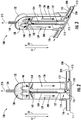
FIG. 1 is an isometric view of a gas trap assembly, in accordance with an embodiment of the present disclosure; -
FIG. 2 is a cutaway view of the gas trap assembly ofFIG. 1 , in accordance with an embodiment of the present disclosure; -
FIG. 3 is a cutaway isometric view of the gas trap assembly ofFIG. 1 , in accordance with an embodiment of the present disclosure; -
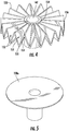
FIG. 4 is an isometric view of a grooved porous media for use in the gas trap assembly ofFIG. 1 , in accordance with an embodiment of the present disclosure; -
FIG. 5 is an isometric view of a non-grooved porous media that was previously used in prior designs of the gas trap assembly ofFIG. 1 ; -
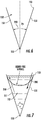
FIG. 6 is a schematic view of dimensions of the grooved porous media ofFIG. 4 , in accordance with an embodiment of the present disclosure; -
FIG. 7 is a schematic view of liquid and gas movement within the groove of the grooved porous media ofFIG. 4 , in accordance with an embodiment of the present disclosure; -
FIG. 8 is a view of a groove having a constant apex angle, in accordance with an embodiment of the present disclosure; -
FIG. 9 is a view of a groove having an apex angle that increases radially outward, in accordance with an embodiment of the present disclosure; and -
FIG. 10 is a view of a groove having an apex angle that decreases radially outward, in accordance with an embodiment of the present disclosure. - A detailed description of one or more embodiments of the disclosed apparatus and method are presented herein by way of exemplification and not limitation with reference to the Figures.
- In a single phase flow loop, liquid phase working fluid circulates through a system for different purposes. Due to corrosion, material compatibility and various other reasons, gas might be generated in the system and enter the liquid stream of working fluid. The generated gas can cause damage to the pump or failure to the system if the gas is allowed to flow into the pump suction side.
- In a gravity field, gas bubbles flowing with the liquid stream can coalesce in the high point of the flow loop due to buoyancy. The locations of gas bubble accumulation can be identified with reasonable accuracy. However, in the microgravity field, the bubbles can flow with the liquid stream and be anywhere. Embodiments disclosed herein seek to separate the gas from the liquid stream and trap the gas in a known location in both terrestrial and microgravity fields.
- Referring now to
FIG. 1 , an isometric view of agas trap assembly 100 is illustrated, according to an embodiment of the present disclosure. Thegas trap assembly 100 includes abase connector housing 110, areservoir 130, and a venting andsampling port 120. Thebase connector housing 110 includes aninflow port 112 and anoutflow port 116. Theoutflow port 116 may be located opposite theinflow port 112. Thereservoir 130 fluidly connects theinflow port 112 to theoutflow port 116. Thereservoir 130 is interposed between theinflow port 112 and theoutflow port 116, such that a workingfluid 200 flows from theinflow port 112 to theoutflow port 116 through thereservoir 130. Thereservoir 130 is composed of atubular housing 136, areservoir dome 132, and afilter housing 140. Thefilter housing 140 is interposed between thereservoir dome 132 and thetubular housing 136, as illustrated inFIG. 1 . The venting andsampling port 120 is attached to thereservoir dome 132. Thetubular housing 136 is attached to thebase connector housing 110. Thefilter housing 140 is attached to thetubular housing 136 and thereservoir dome 132 is attached to thefilter housing 140. - Referring now to
FIGS. 2 and 3 , with continued reference toFIG. 1 , a cross-sectional view of thegas trap assembly 100 is illustrated, according to an embodiment of the present disclosure. Thebase connector housing 110 includes aninlet 113 located within theinflow port 112 to allow a workingfluid 200 to enter thegas trap assembly 100. The workingfluid 200 may be accompanied bygas 210 in the form of gas bubbles. Theinlet 113 is fluidly connected to afluid passage 115 located within thebase connector housing 110. Thefluid passage 115 to may make include a right angle turn to fluidly connect theinlet 113 to a transfer tubes, which are located at 90° relative to each other, as illustrated inFIGS. 2 and 3 . Thefluid passage 115 is fluidly connected to thetransfer tube 134 located within thetubular housing 136. Thetransfer tube 134 is attached to thefluid passage 115 to form a sealedconnection 117. The workingfluid 200 flows from thefluid passage 115, within thebase connector housing 110 to thetransfer tube 134 within thetubular housing 136. Thetransfer tube 134 is fluidly connected to acentral tube 142. The workingfluid 200 flows from thetransfer tube 134 to thecentral tube 142 and then intogas storage space 138 within thereservoir dome 132. The workingfluid 200 andgas 210 is forced to flow in a reverse direction and flow through the groovedporous media 150. In other words, the workingfluid 200 and thegas 210 are forced to make a 180° turn when leaving thecentral tube 142 in order to get to the groovedporous media 150. - At this stage, the
gas 210 is separated from the workingfluid 200 by the groovedporous media 150.Gas 210 is prevented from passing through the groovedporous media 150 and will be stored in thegas storage space 138 for occasional venting out of the venting andsampling port 120. The venting andsampling port 120 may be normally closed during operation but can be opened for liquid sampling of the workingfluid 200 or venting of thegas 210. - The grooved
porous media 150 is configured to separate thegas 210 from the workingfluid 200 by creating a physical separation between the inflow and outflow liquid streams, as discussed further herein. - In terrestrial field (e.g., gravity field) bubbles of the
gas 210 will move toward a direction D1 opposite of a gravity field direction G1 due to a buoyancy effect. The gravity field direction G1 is pointing toward the base inFIGS. 2 and 3 , the blockedgas 210 in thegas storage space 138 will move away from the groovedporous media 150 toward the venting andsampling port 120, which can be vented out whenever necessary. - In a microgravity environment, the distribution of bubbles of the
gas 210 is random. It is possible that the bubbles ofgas 210 are being pushed against the groovedporous media 150 surface by the liquid flow momentum. To avoid any bubbles ofgas 210 accumulating on a surface of the groovedporous media 150 adjacent to thegas storage space 138, the bubbles of thegas 210 are expelled away from the groovedporous media 150 as discussed with reference toFIG. 7 herein. - The working
fluid 200 will migrate through the groovedporous media 150 into aninternal cavity 139 within thetubular housing 136. As illustrated inFIGS. 2 and 3 , thetransfer tube 134 is located within theinternal cavity 139 but is separated from theinternal cavity 139. The only fluid path between the internal cavity and thetube 134 is through the groovedporous media 150. Thetransfer tube 134 passes through a center of theinternal cavity 139. Theinternal cavity 139 is separated from thegas storage space 138 of thereservoir dome 132 by the groovedporous media 150 - The
internal cavity 139 of thetubular housing 136 is fluidly connected to aninternal cavity 119 of thebase connector housing 110. The workingfluid 200 flows from theinternal cavity 139 of thetubular housing 136 to theinternal cavity 119 of thebase connector housing 110. Theinternal cavity 119 of thebase connector housing 110 is fluidly connected to theoutlet 111 of thebase connector housing 110 located in theoutflow port 116. The workingfluid 200 flows from theinternal cavity 119 of thebase connector housing 110 out of theoutlet 111 and exits thegas trap assembly 100. - Referring now to
FIGS. 4 and 5 , with continued reference toFIGS. 1-3 , an isometric view of the groovedporous media 150 is illustrated inFIG. 4 according to an embodiment of the present disclosure and an isometric view of a non-groovedporous media 150a used in prior designs of the gas trap assembly is illustrated. As illustrated inFIG. 5 , the non-groovedporous media 150a is flat and thus does not offer the same advantages as the groovedporous media 150, as discussed herein. - The grooved
porous media 150 circumferentially surrounds thecentral tube 142. The groovedporous media 150 and thecentral tube 142 may form a component assembly for thegas trap assembly 100. The groovedporous media 150 is circular in shape and includes a radiallyinward side 154 located proximate thecentral tube 142 and a radiallyoutward side 156. The groovedporous media 150 extends from the radiallyinward side 154 located proximate thecentral tube 142 to the radiallyoutward side 156. The groovedporous media 150 includes a plurality ofgrooves 152. The groovedporous media 150 is composed of a material with a plurality of pores to allow particles through of a selected size. The groovedporous media 150 may be composed of metallic sintered powders, multilayer screen mesh, felt, or any other similar material known to one of skill in the art. The pores have a pore size. The pore size can range from a few micrometers to few hundreds micrometers. The groovedporous media 150 fluidly divides thereservoir 130 into two portions (e.g., before the groovedporous media 150 and after the grooved porous media 150) in such a way that workingfluid 200 flowing from theinflow port 112 to theoutflow port 116 must flow through the plurality ofgrooves 152 and plurality of pores of the groovedporous media 150. - Each of the
grooves 152 has a same shape as the others and is immediately adjacent to neighboringgrooves 152. In addition, each of thegrooves 152 is formed by two opposingsidewalls 151, such as, for example, a first opposingsidewall 151 and a second opposingsidewall 151. The two opposingsidewalls 151 are tapered toward each other to form abase 153 and an apex 155. Advantageously, thegrooves 152 provide increased surface area for the groovedporous media 150 to filter workingfluid 200 faster than the non-groovedporous media 150a would be able to. Also advantageously, the groovedporous media 150 allows the workingfluid 200 to flow through the groovedporous media 150 with a lower pressure drop. - When the gas-rich liquid (e.g., working
fluid 200 and gas 210) flows into the groovedporous media 150, only the bubbles of thegas 210 that are smaller than the pore size of the groovedporous media 150 will be able to flow through. Any bubbles of thegas 210 that are larger than the pore size will be blocked and stored in thegas storage space 138. Controlling the pore size of the groovedporous media 150 controls the size of the bubble of thegas 210 to flow into a suction pump that is fluidly connected to theoutlet 111 of theoutflow port 116. To prevent any bubbles ofgas 210 from leaking around the groovedporous media 150, the interface between the groovedporous media 150 and interior walls of thefilter housing 140 and the interface between the groovedporous media 150 and thecentral tube 142 are fabricated such that the largest allowable gap is smaller than the pore size of the groovedporous media 150. - Referring now to
FIGS. 6 and 7 , with continued reference toFIGS. 1-5 , a schematic view of thegroove 152 is illustrated, according to an embodiment of the present disclosure. In a microgravity environment the workingfluid 200 will move from the base 153 in a direction of the apex 155 and thegas 210 will be pushed from the apex 155 to a direction of the base 153 by the working fluid replenishing intogroove 152 toward the apex 155 if half of anapex angle 250 is smaller than the difference between a right angle (i.e., 90°) and a solid-liquid contact angle. The solid liquid contact angle may vary from liquid-to-liquid and thus depends upon a type of workingfluid 200 utilized. The embodiments disclosed may be applicable for any solid-liquid pair as long as the liquid can "wet" the solid material or in other words the solid-liquid contact angel is smaller than 90°. - The apex 155 has an
apex angle 250 as measured between two opposingside walls 151. In an embodiment, theapex angle 250 is equal to a selected angle of 2β where β is less than 90° minus a solid-liquid contact angle. In other words the selected angle of 2β is equal to 2 X ((β < 90) - Solid-Liquid Contact Angle). In other words the selected angle 2β is less than or equal to twice the summation of an angle less than 90° minus a Solid-Liquid Contact Angle of the workingfluid 200. That is, theapex angle 250 is defined such that, for a fluid flow of workingfluid 200 andgas 210 moving through one of thechannels 140 in a microgravity environment where a portion of the fluid flow is in a liquid phase (e.g., working fluid 200) and another portion of the fluid flow is in a vapor phase (e.g., gas), the portion of the fluid flow in the liquid phase (e.g., working fluid 200) within aparticular groove 152 will move in theparticular groove 152 from the base 153 to the apex 155 and the portion of the fluid flow in the vapor phase (e.g., gas) within theparticular groove 152 will move in theparticular groove 152 from the apex 155 to thebase 153. - Referring now to
FIGS. 8 ,9, and 10 , with continued reference toFIGS. 1-7 , apex angles 250 of the groovedporous media 150 are illustrated, in accordance with an embodiment of the present disclosure. - The
apex angle 250 is measured between the two opposingsidewalls 151 at the apex 155. The opposingsidewalls 151 and each of the plurality ofgrooves 152 extend from the radiallyinward side 154 radially outward to the radiallyoutward side 156. - In one embodiment, the
apex angle 250 at the radiallyinward side 154 may be equivalent to theapex angle 250 at the radiallyoutward side 156, as illustrated inFIG. 8 . InFIG. 8 theapex angle 250 at the radiallyinward side 154 is equivalent to 2β and theapex angle 250 at the radiallyoutward side 156 is equivalent to 2β. InFIG. 8 theapex angle 250 remains constant or unchanged along thegroove 152 from the radiallyinward side 154 the radiallyoutward side 156. - In one embodiment, the
apex angle 250 at the radiallyinward side 154 may be unequal to theapex angle 250 at the radiallyoutward side 156, as illustrated inFIGS. 9 and 10 . Theapex angle 250 may vary in size along thegroove 152 from the radiallyinward side 154 the radiallyoutward side 156. - In one embodiment, the
apex angle 250 at the radiallyinward side 154 may be less than theapex angle 250 at the radiallyoutward side 156, as illustrated inFIG. 9 . InFIG. 9 theapex angle 250 at the radiallyinward side 154 is equivalent to 2α and theapex angle 250 at the radiallyoutward side 156 is equivalent to 2β. InFIG. 9 theapex angle 250 increases in size along thegroove 152 from the radiallyinward side 154 the radiallyoutward side 156. - In one embodiment, the
apex angle 250 at the radiallyinward side 154 may be greater than theapex angle 250 at the radiallyoutward side 156, as illustrated inFIG. 10 . InFIG. 10 theapex angle 250 at the radiallyinward side 154 is equivalent to 2β and theapex angle 250 at the radiallyoutward side 156 is equivalent to 2γ. InFIG. 10 theapex angle 250 decreases in size along thegroove 152 from the radiallyinward side 154 the radiallyoutward side 156. - Technical effects and benefits of the features described herein include utilizing a grooved porous media to filter gas bubbles from a working fluid in both microgravity environments and terrestrial environments.
- A detailed description of one or more embodiments of the disclosed apparatus and method are presented herein by way of exemplification and not limitation with reference to the Figures.
- The term "about" is intended to include the degree of error associated with measurement of the particular quantity based upon the equipment available at the time of filing the application.
- The terminology used herein is for the purpose of describing particular embodiments only and is not intended to be limiting of the present disclosure. As used herein, the singular forms "a", "an" and "the" are intended to include the plural forms as well, unless the context clearly indicates otherwise. It will be further understood that the terms "comprises" and/or "comprising," when used in this specification, specify the presence of stated features, integers, steps, operations, elements, and/or components, but do not preclude the presence or addition of one or more other features, integers, steps, operations, element components, and/or groups thereof.
- While the present disclosure has been described with reference to an exemplary embodiment or embodiments, it will be understood by those skilled in the art that various changes may be made and equivalents may be substituted for elements thereof without departing from the scope of the present disclosure. In addition, many modifications may be made to adapt a particular situation or material to the teachings of the present disclosure without departing from the essential scope thereof. Therefore, it is intended that the present disclosure not be limited to the particular embodiment disclosed as the best mode contemplated for carrying out this present disclosure, but that the present disclosure will include all embodiments falling within the scope of the claims.
Claims (15)
- A gas trap assembly (100), comprising:a base connector housing (110) comprising an inflow port and an outflow port;a reservoir (130) fluidly connecting the inflow port to the outflow port; anda grooved porous media (150) located within the reservoir, the grooved porous media comprising a plurality of grooves (152) and composed of a material having a plurality of pores of a selected size,wherein the grooved porous media fluidly divides the reservoir into two portions in such a way that a working fluid flowing from the inflow port to the outflow port must flow through the plurality of grooves and the plurality of pores of the grooved porous media, andwherein the plurality of grooves and the plurality of pores are configured to prevent gas from passing through the grooved porous media.
- The gas trap assembly of claim 1, wherein each of the plurality of grooves are formed by two opposing sidewalls, which form a base and an apex with an apex angle measured between the two opposing sidewalls at the apex and defined such that:the working fluid within each of the plurality of grooves will move from the base to the apex, andthe gas within each of the plurality of grooves will move from the apex to the base.
- The gas trap assembly of claim 1 or 2, wherein each of the plurality of grooves are formed by two opposing sidewalls, which form a base and an apex with an apex angle opposite the base.
- The gas trap assembly of claim 3, further comprising
a central tube circumferentially surrounded by the grooved porous media, wherein the two opposing sidewalls and each of the plurality of grooves extend from a radially inward side of the grooved porous media located proximate the central tube to a radially outward side of the grooved porous media. - The gas trap assembly of claim 4, wherein the apex angle at the radially inward side is equivalent to the apex angle at the radially outward side, or wherein the apex angle at the radially inward side is less than the apex angle at the radially outward side..
- The gas trap assembly of claim 4, wherein the apex angle remains constant along each of the plurality of grooves from the radially inward side to the radially outward side, or wherein the apex angle decreases along each of the plurality of grooves from the radially inward side to the radially outward side or wherein the apex angle increases along each of the plurality of grooves from the radially inward side to the radially outward side..
- The gas trap assembly of claim 4, wherein the apex angle at the radially inward side is greater than the apex angle at the radially outward side.
- The gas trap assembly of claim 4, wherein the apex angle is less than or equal to twice a summation of an angle less than 90° minus a Solid-Liquid Contact Angle of the working fluid.
- The gas trap assembly of claim 4, wherein the reservoir further comprises:a tubular housing;reservoir dome; anda filter housing interposed between the reservoir dome and the tubular housing,wherein the grooved porous media is located within the tubular housing.
- The gas trap assembly of claim 9, wherein the base connector housing further comprising a fluid passage fluidly connected to an inlet in the inflow port, and
wherein the gas trap assembly further comprises a transfer tube fluidly connecting the fluid passage to the central tube. - The gas trap assembly of claim 9 or 10, wherein the central tube is fluidly connected to a gas storage space within the reservoir dome, and optionally wherein the transfer tube is located within an internal cavity of the transfer housing and separated from the internal cavity, and wherein the internal cavity is separated from the gas storage space by the grooved porous media.
- A component assembly for a gas trap assembly, comprising:a central tube;a grooved porous media circumferentially surrounding the central tube, the grooved porous media comprising a plurality of grooves and composed of a material comprising a plurality of pores of a selected size,wherein the plurality of grooves and the plurality of pores are configured to prevent gas from passing through the grooved porous media.
- The component assembly of claim 12, wherein each of the plurality of grooves are formed by two opposing sidewalls, which form a base and an apex with an apex angle measured between the two opposing sidewalls at the apex and defined such that:a working fluid within each of the plurality of grooves will move from the base to the apex, andthe gas within each of the plurality of grooves will move from the apex to the base.
- The component assembly of claim 13, wherein each of the plurality of grooves are formed by two opposing sidewalls, which form a base and an apex with an apex angle opposite the base.
- The component assembly of claim 14, wherein the grooved porous media further comprises a radially inward side of the grooved porous media located proximate the central tube and a radially outward side of the grooved porous media,
wherein the two opposing sidewalls and each of the plurality of grooves extend from the radially inward side to the radially outward side, and optionally wherein the apex angle at the radially inward side is equivalent to the apex angle at the radially outward side.
Applications Claiming Priority (1)
| Application Number | Priority Date | Filing Date | Title |
|---|---|---|---|
| US16/895,520 US11446585B2 (en) | 2020-06-08 | 2020-06-08 | Grooved porous media gas trap for terrestrial and microgravity environment |
Publications (2)
| Publication Number | Publication Date |
|---|---|
| EP3922332A1 true EP3922332A1 (en) | 2021-12-15 |
| EP3922332B1 EP3922332B1 (en) | 2024-03-06 |
Family
ID=76305768
Family Applications (1)
| Application Number | Title | Priority Date | Filing Date |
|---|---|---|---|
| EP21177939.2A Active EP3922332B1 (en) | 2020-06-08 | 2021-06-07 | Grooved porous media gas trap for terrestrial and microgravity environment |
Country Status (3)
| Country | Link |
|---|---|
| US (1) | US11446585B2 (en) |
| EP (1) | EP3922332B1 (en) |
| JP (1) | JP7737817B2 (en) |
Citations (6)
| Publication number | Priority date | Publication date | Assignee | Title |
|---|---|---|---|---|
| GB247990A (en) * | 1925-02-20 | 1927-02-10 | Alexander Bernhard Drager | Improvements in or relating to respiratory cartridges for self-contained breathing apparatus |
| US4344777A (en) * | 1980-01-07 | 1982-08-17 | Siposs George G | Directed flow bubble trap for arterial blood |
| US4758337A (en) * | 1985-11-23 | 1988-07-19 | Sartorius Gmbh | Filter for filtering human blood, especially in an extracorporeal circulatory system |
| EP0284404A2 (en) * | 1987-03-27 | 1988-09-28 | Pall Corporation | Filter disc |
| US4806135A (en) * | 1988-03-01 | 1989-02-21 | Siposs George G | Bubble trap for phase-separating gas bubbles from flowing liquids |
| US5618425A (en) * | 1993-04-30 | 1997-04-08 | Terumo Kabushiki Kaisha | Filtering apparatus with a pleated filtering element embedded in a filling material |
Family Cites Families (21)
| Publication number | Priority date | Publication date | Assignee | Title |
|---|---|---|---|---|
| US3386230A (en) * | 1966-12-27 | 1968-06-04 | Donaldson Co Inc | Liquid and gas separator |
| JPS5034877U (en) * | 1973-07-24 | 1975-04-14 | ||
| GB2151505A (en) * | 1983-12-21 | 1985-07-24 | John William Brookes | Improvements in oil/gas separators |
| JPS61291015A (en) * | 1985-06-15 | 1986-12-20 | Tsuchiya Mfg Co Ltd | Filter element |
| US5474688A (en) * | 1993-09-29 | 1995-12-12 | Uop | Process for phase separation |
| JP2000126507A (en) * | 1998-10-22 | 2000-05-09 | Nikkiso Co Ltd | Defoaming device |
| US10502448B1 (en) * | 2002-01-02 | 2019-12-10 | United States Of America As Represented By The Secretary Of The Air Force | Self-clearing vents based on droplet expulsion |
| US6986428B2 (en) | 2003-05-14 | 2006-01-17 | 3M Innovative Properties Company | Fluid separation membrane module |
| DE112005002144B4 (en) | 2004-09-06 | 2022-03-31 | Toyota Jidosha Kabushiki Kaisha | fuel cell system |
| US8584518B2 (en) * | 2010-06-30 | 2013-11-19 | Rigsat Communications Inc. | Gas trap for drilling mud having quick-release separable lower section |
| JP5183765B2 (en) * | 2011-04-07 | 2013-04-17 | キュノ株式会社 | Filter housing |
| US8696794B2 (en) * | 2011-05-20 | 2014-04-15 | Hamilton Sundstrand Space Systems International, Inc. | Microgravity passive phase separator |
| WO2013003769A2 (en) * | 2011-06-30 | 2013-01-03 | Donaldson Company, Inc. | Air/oil separator assemblies; components; and, methods |
| JP5910401B2 (en) * | 2012-08-03 | 2016-04-27 | 東京エレクトロン株式会社 | Method of operating processing liquid supply apparatus, processing liquid supply apparatus, and storage medium |
| JP5674755B2 (en) * | 2012-12-26 | 2015-02-25 | 株式会社ミンガス | Gas separator |
| US10612824B2 (en) * | 2016-05-06 | 2020-04-07 | Hamilton Sundstrand Corporation | Gas-liquid phase separator |
| US10345052B2 (en) * | 2016-12-21 | 2019-07-09 | Hamilton Sundstrand Corporation | Porous media evaporator |
| US10330361B2 (en) * | 2017-01-26 | 2019-06-25 | Hamilton Sundstrand Corporation | Passive liquid collecting device |
| JP6914093B2 (en) * | 2017-04-27 | 2021-08-04 | ヤマシンフィルタ株式会社 | strainer |
| JP2019130674A (en) | 2018-01-29 | 2019-08-08 | セイコーエプソン株式会社 | Flow passage member and liquid discharge device |
| US10926197B2 (en) * | 2018-06-22 | 2021-02-23 | Hamilton Sunstrand Corporation | Multifunctional phase separation apparatus |
-
2020
- 2020-06-08 US US16/895,520 patent/US11446585B2/en active Active
-
2021
- 2021-05-25 JP JP2021087302A patent/JP7737817B2/en active Active
- 2021-06-07 EP EP21177939.2A patent/EP3922332B1/en active Active
Patent Citations (6)
| Publication number | Priority date | Publication date | Assignee | Title |
|---|---|---|---|---|
| GB247990A (en) * | 1925-02-20 | 1927-02-10 | Alexander Bernhard Drager | Improvements in or relating to respiratory cartridges for self-contained breathing apparatus |
| US4344777A (en) * | 1980-01-07 | 1982-08-17 | Siposs George G | Directed flow bubble trap for arterial blood |
| US4758337A (en) * | 1985-11-23 | 1988-07-19 | Sartorius Gmbh | Filter for filtering human blood, especially in an extracorporeal circulatory system |
| EP0284404A2 (en) * | 1987-03-27 | 1988-09-28 | Pall Corporation | Filter disc |
| US4806135A (en) * | 1988-03-01 | 1989-02-21 | Siposs George G | Bubble trap for phase-separating gas bubbles from flowing liquids |
| US5618425A (en) * | 1993-04-30 | 1997-04-08 | Terumo Kabushiki Kaisha | Filtering apparatus with a pleated filtering element embedded in a filling material |
Also Published As
| Publication number | Publication date |
|---|---|
| JP2021192904A (en) | 2021-12-23 |
| JP7737817B2 (en) | 2025-09-11 |
| EP3922332B1 (en) | 2024-03-06 |
| US11446585B2 (en) | 2022-09-20 |
| US20210379506A1 (en) | 2021-12-09 |
Similar Documents
| Publication | Publication Date | Title |
|---|---|---|
| EP3727637B1 (en) | Filter for liquid flow based devices and systems | |
| US6227288B1 (en) | Multifunctional capillary system for loop heat pipe statement of government interest | |
| EP3293469B1 (en) | Passive liquid collecting device | |
| US20190091609A1 (en) | Membrane Gas/Liquid Contactor | |
| US7937990B2 (en) | Liquid chromatograph and separation column | |
| US20130001145A1 (en) | Micro-Machined Frit and Flow Distributor Devices for Liquid Chromatography | |
| CN105035363B (en) | The selection method of tank exhaust apparatus and tank exhaust apparatus | |
| US11446585B2 (en) | Grooved porous media gas trap for terrestrial and microgravity environment | |
| EP3637024B1 (en) | Thermal control loop | |
| EP4051411A1 (en) | Two-phase separator devices incorporating inertial separation and porous media extraction | |
| JP2005515454A (en) | Sealed integrated liquid chromatography system | |
| CN102348895A (en) | Pump having a filter arrangement | |
| CN114210112A (en) | Branched filters and methods of use | |
| JP2015009239A (en) | Fluid degassing module with spiral membrane | |
| US20250001338A1 (en) | Multiphase superhydrophobic separator | |
| EP4058170A1 (en) | Apparatus and method | |
| EP3643377B1 (en) | Liquid vapor separator | |
| CN214513145U (en) | Flow guide separation device | |
| CN114210114A (en) | Branched filters and methods of use | |
| SU1318247A1 (en) | Apparatus for removing gas from liquid | |
| JP2026514570A (en) | High-pressure fluid processing apparatus for liquid chromatography | |
| WO2025099740A1 (en) | Synchronization of capillary flow in parallel microchannels using passive microfluidic valves | |
| CN108905623A (en) | membrane separation device | |
| CN109825417A (en) | A droplet guiding device | |
| HK40011792A (en) | Device for administering a liquid medicament |
Legal Events
| Date | Code | Title | Description |
|---|---|---|---|
| PUAI | Public reference made under article 153(3) epc to a published international application that has entered the european phase |
Free format text: ORIGINAL CODE: 0009012 |
|
| STAA | Information on the status of an ep patent application or granted ep patent |
Free format text: STATUS: THE APPLICATION HAS BEEN PUBLISHED |
|
| AK | Designated contracting states |
Kind code of ref document: A1 Designated state(s): AL AT BE BG CH CY CZ DE DK EE ES FI FR GB GR HR HU IE IS IT LI LT LU LV MC MK MT NL NO PL PT RO RS SE SI SK SM TR |
|
| B565 | Issuance of search results under rule 164(2) epc |
Effective date: 20210924 |
|
| STAA | Information on the status of an ep patent application or granted ep patent |
Free format text: STATUS: REQUEST FOR EXAMINATION WAS MADE |
|
| 17P | Request for examination filed |
Effective date: 20220610 |
|
| RBV | Designated contracting states (corrected) |
Designated state(s): AL AT BE BG CH CY CZ DE DK EE ES FI FR GB GR HR HU IE IS IT LI LT LU LV MC MK MT NL NO PL PT RO RS SE SI SK SM TR |
|
| STAA | Information on the status of an ep patent application or granted ep patent |
Free format text: STATUS: EXAMINATION IS IN PROGRESS |
|
| 17Q | First examination report despatched |
Effective date: 20220928 |
|
| GRAP | Despatch of communication of intention to grant a patent |
Free format text: ORIGINAL CODE: EPIDOSNIGR1 |
|
| STAA | Information on the status of an ep patent application or granted ep patent |
Free format text: STATUS: GRANT OF PATENT IS INTENDED |
|
| INTG | Intention to grant announced |
Effective date: 20231011 |
|
| GRAS | Grant fee paid |
Free format text: ORIGINAL CODE: EPIDOSNIGR3 |
|
| GRAA | (expected) grant |
Free format text: ORIGINAL CODE: 0009210 |
|
| STAA | Information on the status of an ep patent application or granted ep patent |
Free format text: STATUS: THE PATENT HAS BEEN GRANTED |
|
| AK | Designated contracting states |
Kind code of ref document: B1 Designated state(s): AL AT BE BG CH CY CZ DE DK EE ES FI FR GB GR HR HU IE IS IT LI LT LU LV MC MK MT NL NO PL PT RO RS SE SI SK SM TR |
|
| REG | Reference to a national code |
Ref country code: CH Ref legal event code: EP |
|
| REG | Reference to a national code |
Ref country code: DE Ref legal event code: R096 Ref document number: 602021010000 Country of ref document: DE |
|
| REG | Reference to a national code |
Ref country code: IE Ref legal event code: FG4D |
|
| REG | Reference to a national code |
Ref country code: LT Ref legal event code: MG9D |
|
| PG25 | Lapsed in a contracting state [announced via postgrant information from national office to epo] |
Ref country code: LT Free format text: LAPSE BECAUSE OF FAILURE TO SUBMIT A TRANSLATION OF THE DESCRIPTION OR TO PAY THE FEE WITHIN THE PRESCRIBED TIME-LIMIT Effective date: 20240306 |
|
| REG | Reference to a national code |
Ref country code: NL Ref legal event code: MP Effective date: 20240306 |
|
| PG25 | Lapsed in a contracting state [announced via postgrant information from national office to epo] |
Ref country code: GR Free format text: LAPSE BECAUSE OF FAILURE TO SUBMIT A TRANSLATION OF THE DESCRIPTION OR TO PAY THE FEE WITHIN THE PRESCRIBED TIME-LIMIT Effective date: 20240607 |
|
| PG25 | Lapsed in a contracting state [announced via postgrant information from national office to epo] |
Ref country code: HR Free format text: LAPSE BECAUSE OF FAILURE TO SUBMIT A TRANSLATION OF THE DESCRIPTION OR TO PAY THE FEE WITHIN THE PRESCRIBED TIME-LIMIT Effective date: 20240306 Ref country code: RS Free format text: LAPSE BECAUSE OF FAILURE TO SUBMIT A TRANSLATION OF THE DESCRIPTION OR TO PAY THE FEE WITHIN THE PRESCRIBED TIME-LIMIT Effective date: 20240606 |
|
| PG25 | Lapsed in a contracting state [announced via postgrant information from national office to epo] |
Ref country code: ES Free format text: LAPSE BECAUSE OF FAILURE TO SUBMIT A TRANSLATION OF THE DESCRIPTION OR TO PAY THE FEE WITHIN THE PRESCRIBED TIME-LIMIT Effective date: 20240306 |
|
| PG25 | Lapsed in a contracting state [announced via postgrant information from national office to epo] |
Ref country code: RS Free format text: LAPSE BECAUSE OF FAILURE TO SUBMIT A TRANSLATION OF THE DESCRIPTION OR TO PAY THE FEE WITHIN THE PRESCRIBED TIME-LIMIT Effective date: 20240606 Ref country code: NO Free format text: LAPSE BECAUSE OF FAILURE TO SUBMIT A TRANSLATION OF THE DESCRIPTION OR TO PAY THE FEE WITHIN THE PRESCRIBED TIME-LIMIT Effective date: 20240606 Ref country code: LT Free format text: LAPSE BECAUSE OF FAILURE TO SUBMIT A TRANSLATION OF THE DESCRIPTION OR TO PAY THE FEE WITHIN THE PRESCRIBED TIME-LIMIT Effective date: 20240306 Ref country code: HR Free format text: LAPSE BECAUSE OF FAILURE TO SUBMIT A TRANSLATION OF THE DESCRIPTION OR TO PAY THE FEE WITHIN THE PRESCRIBED TIME-LIMIT Effective date: 20240306 Ref country code: GR Free format text: LAPSE BECAUSE OF FAILURE TO SUBMIT A TRANSLATION OF THE DESCRIPTION OR TO PAY THE FEE WITHIN THE PRESCRIBED TIME-LIMIT Effective date: 20240607 Ref country code: FI Free format text: LAPSE BECAUSE OF FAILURE TO SUBMIT A TRANSLATION OF THE DESCRIPTION OR TO PAY THE FEE WITHIN THE PRESCRIBED TIME-LIMIT Effective date: 20240306 Ref country code: ES Free format text: LAPSE BECAUSE OF FAILURE TO SUBMIT A TRANSLATION OF THE DESCRIPTION OR TO PAY THE FEE WITHIN THE PRESCRIBED TIME-LIMIT Effective date: 20240306 Ref country code: BG Free format text: LAPSE BECAUSE OF FAILURE TO SUBMIT A TRANSLATION OF THE DESCRIPTION OR TO PAY THE FEE WITHIN THE PRESCRIBED TIME-LIMIT Effective date: 20240306 |
|
| REG | Reference to a national code |
Ref country code: AT Ref legal event code: MK05 Ref document number: 1662928 Country of ref document: AT Kind code of ref document: T Effective date: 20240306 |
|
| PG25 | Lapsed in a contracting state [announced via postgrant information from national office to epo] |
Ref country code: SE Free format text: LAPSE BECAUSE OF FAILURE TO SUBMIT A TRANSLATION OF THE DESCRIPTION OR TO PAY THE FEE WITHIN THE PRESCRIBED TIME-LIMIT Effective date: 20240306 Ref country code: LV Free format text: LAPSE BECAUSE OF FAILURE TO SUBMIT A TRANSLATION OF THE DESCRIPTION OR TO PAY THE FEE WITHIN THE PRESCRIBED TIME-LIMIT Effective date: 20240306 |
|
| PG25 | Lapsed in a contracting state [announced via postgrant information from national office to epo] |
Ref country code: NL Free format text: LAPSE BECAUSE OF FAILURE TO SUBMIT A TRANSLATION OF THE DESCRIPTION OR TO PAY THE FEE WITHIN THE PRESCRIBED TIME-LIMIT Effective date: 20240306 |
|
| PG25 | Lapsed in a contracting state [announced via postgrant information from national office to epo] |
Ref country code: NL Free format text: LAPSE BECAUSE OF FAILURE TO SUBMIT A TRANSLATION OF THE DESCRIPTION OR TO PAY THE FEE WITHIN THE PRESCRIBED TIME-LIMIT Effective date: 20240306 |
|
| PG25 | Lapsed in a contracting state [announced via postgrant information from national office to epo] |
Ref country code: IS Free format text: LAPSE BECAUSE OF FAILURE TO SUBMIT A TRANSLATION OF THE DESCRIPTION OR TO PAY THE FEE WITHIN THE PRESCRIBED TIME-LIMIT Effective date: 20240706 |
|
| PG25 | Lapsed in a contracting state [announced via postgrant information from national office to epo] |
Ref country code: PT Free format text: LAPSE BECAUSE OF FAILURE TO SUBMIT A TRANSLATION OF THE DESCRIPTION OR TO PAY THE FEE WITHIN THE PRESCRIBED TIME-LIMIT Effective date: 20240708 Ref country code: SM Free format text: LAPSE BECAUSE OF FAILURE TO SUBMIT A TRANSLATION OF THE DESCRIPTION OR TO PAY THE FEE WITHIN THE PRESCRIBED TIME-LIMIT Effective date: 20240306 |
|
| PG25 | Lapsed in a contracting state [announced via postgrant information from national office to epo] |
Ref country code: EE Free format text: LAPSE BECAUSE OF FAILURE TO SUBMIT A TRANSLATION OF THE DESCRIPTION OR TO PAY THE FEE WITHIN THE PRESCRIBED TIME-LIMIT Effective date: 20240306 Ref country code: CZ Free format text: LAPSE BECAUSE OF FAILURE TO SUBMIT A TRANSLATION OF THE DESCRIPTION OR TO PAY THE FEE WITHIN THE PRESCRIBED TIME-LIMIT Effective date: 20240306 |
|
| PG25 | Lapsed in a contracting state [announced via postgrant information from national office to epo] |
Ref country code: AT Free format text: LAPSE BECAUSE OF FAILURE TO SUBMIT A TRANSLATION OF THE DESCRIPTION OR TO PAY THE FEE WITHIN THE PRESCRIBED TIME-LIMIT Effective date: 20240306 |
|
| PG25 | Lapsed in a contracting state [announced via postgrant information from national office to epo] |
Ref country code: PL Free format text: LAPSE BECAUSE OF FAILURE TO SUBMIT A TRANSLATION OF THE DESCRIPTION OR TO PAY THE FEE WITHIN THE PRESCRIBED TIME-LIMIT Effective date: 20240306 |
|
| PG25 | Lapsed in a contracting state [announced via postgrant information from national office to epo] |
Ref country code: SK Free format text: LAPSE BECAUSE OF FAILURE TO SUBMIT A TRANSLATION OF THE DESCRIPTION OR TO PAY THE FEE WITHIN THE PRESCRIBED TIME-LIMIT Effective date: 20240306 |
|
| PG25 | Lapsed in a contracting state [announced via postgrant information from national office to epo] |
Ref country code: SM Free format text: LAPSE BECAUSE OF FAILURE TO SUBMIT A TRANSLATION OF THE DESCRIPTION OR TO PAY THE FEE WITHIN THE PRESCRIBED TIME-LIMIT Effective date: 20240306 Ref country code: SK Free format text: LAPSE BECAUSE OF FAILURE TO SUBMIT A TRANSLATION OF THE DESCRIPTION OR TO PAY THE FEE WITHIN THE PRESCRIBED TIME-LIMIT Effective date: 20240306 Ref country code: RO Free format text: LAPSE BECAUSE OF FAILURE TO SUBMIT A TRANSLATION OF THE DESCRIPTION OR TO PAY THE FEE WITHIN THE PRESCRIBED TIME-LIMIT Effective date: 20240306 Ref country code: PT Free format text: LAPSE BECAUSE OF FAILURE TO SUBMIT A TRANSLATION OF THE DESCRIPTION OR TO PAY THE FEE WITHIN THE PRESCRIBED TIME-LIMIT Effective date: 20240708 Ref country code: PL Free format text: LAPSE BECAUSE OF FAILURE TO SUBMIT A TRANSLATION OF THE DESCRIPTION OR TO PAY THE FEE WITHIN THE PRESCRIBED TIME-LIMIT Effective date: 20240306 Ref country code: IS Free format text: LAPSE BECAUSE OF FAILURE TO SUBMIT A TRANSLATION OF THE DESCRIPTION OR TO PAY THE FEE WITHIN THE PRESCRIBED TIME-LIMIT Effective date: 20240706 Ref country code: EE Free format text: LAPSE BECAUSE OF FAILURE TO SUBMIT A TRANSLATION OF THE DESCRIPTION OR TO PAY THE FEE WITHIN THE PRESCRIBED TIME-LIMIT Effective date: 20240306 Ref country code: CZ Free format text: LAPSE BECAUSE OF FAILURE TO SUBMIT A TRANSLATION OF THE DESCRIPTION OR TO PAY THE FEE WITHIN THE PRESCRIBED TIME-LIMIT Effective date: 20240306 Ref country code: AT Free format text: LAPSE BECAUSE OF FAILURE TO SUBMIT A TRANSLATION OF THE DESCRIPTION OR TO PAY THE FEE WITHIN THE PRESCRIBED TIME-LIMIT Effective date: 20240306 |
|
| PG25 | Lapsed in a contracting state [announced via postgrant information from national office to epo] |
Ref country code: IT Free format text: LAPSE BECAUSE OF FAILURE TO SUBMIT A TRANSLATION OF THE DESCRIPTION OR TO PAY THE FEE WITHIN THE PRESCRIBED TIME-LIMIT Effective date: 20240306 |
|
| REG | Reference to a national code |
Ref country code: DE Ref legal event code: R097 Ref document number: 602021010000 Country of ref document: DE |
|
| PG25 | Lapsed in a contracting state [announced via postgrant information from national office to epo] |
Ref country code: IT Free format text: LAPSE BECAUSE OF FAILURE TO SUBMIT A TRANSLATION OF THE DESCRIPTION OR TO PAY THE FEE WITHIN THE PRESCRIBED TIME-LIMIT Effective date: 20240306 |
|
| PLBE | No opposition filed within time limit |
Free format text: ORIGINAL CODE: 0009261 |
|
| STAA | Information on the status of an ep patent application or granted ep patent |
Free format text: STATUS: NO OPPOSITION FILED WITHIN TIME LIMIT |
|
| PG25 | Lapsed in a contracting state [announced via postgrant information from national office to epo] |
Ref country code: DK Free format text: LAPSE BECAUSE OF FAILURE TO SUBMIT A TRANSLATION OF THE DESCRIPTION OR TO PAY THE FEE WITHIN THE PRESCRIBED TIME-LIMIT Effective date: 20240306 |
|
| PG25 | Lapsed in a contracting state [announced via postgrant information from national office to epo] |
Ref country code: DK Free format text: LAPSE BECAUSE OF FAILURE TO SUBMIT A TRANSLATION OF THE DESCRIPTION OR TO PAY THE FEE WITHIN THE PRESCRIBED TIME-LIMIT Effective date: 20240306 Ref country code: MC Free format text: LAPSE BECAUSE OF FAILURE TO SUBMIT A TRANSLATION OF THE DESCRIPTION OR TO PAY THE FEE WITHIN THE PRESCRIBED TIME-LIMIT Effective date: 20240306 |
|
| REG | Reference to a national code |
Ref country code: CH Ref legal event code: PL |
|
| 26N | No opposition filed |
Effective date: 20241209 |
|
| PG25 | Lapsed in a contracting state [announced via postgrant information from national office to epo] |
Ref country code: LU Free format text: LAPSE BECAUSE OF NON-PAYMENT OF DUE FEES Effective date: 20240607 |
|
| PG25 | Lapsed in a contracting state [announced via postgrant information from national office to epo] |
Ref country code: IE Free format text: LAPSE BECAUSE OF NON-PAYMENT OF DUE FEES Effective date: 20240607 |
|
| PG25 | Lapsed in a contracting state [announced via postgrant information from national office to epo] |
Ref country code: SI Free format text: LAPSE BECAUSE OF FAILURE TO SUBMIT A TRANSLATION OF THE DESCRIPTION OR TO PAY THE FEE WITHIN THE PRESCRIBED TIME-LIMIT Effective date: 20240306 Ref country code: BE Free format text: LAPSE BECAUSE OF NON-PAYMENT OF DUE FEES Effective date: 20240630 Ref country code: CH Free format text: LAPSE BECAUSE OF NON-PAYMENT OF DUE FEES Effective date: 20240630 |
|
| REG | Reference to a national code |
Ref country code: BE Ref legal event code: MM Effective date: 20240630 |
|
| PGFP | Annual fee paid to national office [announced via postgrant information from national office to epo] |
Ref country code: DE Payment date: 20250520 Year of fee payment: 5 |
|
| PGFP | Annual fee paid to national office [announced via postgrant information from national office to epo] |
Ref country code: GB Payment date: 20250520 Year of fee payment: 5 |
|
| PGFP | Annual fee paid to national office [announced via postgrant information from national office to epo] |
Ref country code: FR Payment date: 20250520 Year of fee payment: 5 |
|
| PG25 | Lapsed in a contracting state [announced via postgrant information from national office to epo] |
Ref country code: CY Free format text: LAPSE BECAUSE OF FAILURE TO SUBMIT A TRANSLATION OF THE DESCRIPTION OR TO PAY THE FEE WITHIN THE PRESCRIBED TIME-LIMIT; INVALID AB INITIO Effective date: 20210607 |
|
| PG25 | Lapsed in a contracting state [announced via postgrant information from national office to epo] |
Ref country code: HU Free format text: LAPSE BECAUSE OF FAILURE TO SUBMIT A TRANSLATION OF THE DESCRIPTION OR TO PAY THE FEE WITHIN THE PRESCRIBED TIME-LIMIT; INVALID AB INITIO Effective date: 20210607 |