EP3921207B1 - Taschenhaken für den heckbereich eines kraftfahrzeuges - Google Patents
Taschenhaken für den heckbereich eines kraftfahrzeuges Download PDFInfo
- Publication number
- EP3921207B1 EP3921207B1 EP19835255.1A EP19835255A EP3921207B1 EP 3921207 B1 EP3921207 B1 EP 3921207B1 EP 19835255 A EP19835255 A EP 19835255A EP 3921207 B1 EP3921207 B1 EP 3921207B1
- Authority
- EP
- European Patent Office
- Prior art keywords
- pillar
- console
- bag hook
- trim
- overlapping area
- Prior art date
- Legal status (The legal status is an assumption and is not a legal conclusion. Google has not performed a legal analysis and makes no representation as to the accuracy of the status listed.)
- Active
Links
Images

Classifications
-
- B—PERFORMING OPERATIONS; TRANSPORTING
- B60—VEHICLES IN GENERAL
- B60R—VEHICLES, VEHICLE FITTINGS, OR VEHICLE PARTS, NOT OTHERWISE PROVIDED FOR
- B60R13/00—Elements for body-finishing, identifying, or decorating; Arrangements or adaptations for advertising purposes
- B60R13/02—Internal Trim mouldings ; Internal Ledges; Wall liners for passenger compartments; Roof liners
- B60R13/0237—Side or rear panels
- B60R13/025—Pillars; Roof rails
-
- B—PERFORMING OPERATIONS; TRANSPORTING
- B60—VEHICLES IN GENERAL
- B60R—VEHICLES, VEHICLE FITTINGS, OR VEHICLE PARTS, NOT OTHERWISE PROVIDED FOR
- B60R13/00—Elements for body-finishing, identifying, or decorating; Arrangements or adaptations for advertising purposes
- B60R13/02—Internal Trim mouldings ; Internal Ledges; Wall liners for passenger compartments; Roof liners
- B60R13/0237—Side or rear panels
-
- B—PERFORMING OPERATIONS; TRANSPORTING
- B60—VEHICLES IN GENERAL
- B60R—VEHICLES, VEHICLE FITTINGS, OR VEHICLE PARTS, NOT OTHERWISE PROVIDED FOR
- B60R7/00—Stowing or holding appliances inside vehicle primarily intended for personal property smaller than suit-cases, e.g. travelling articles, or maps
- B60R7/08—Disposition of racks, clips, holders, containers or the like for supporting specific articles
- B60R7/10—Disposition of racks, clips, holders, containers or the like for supporting specific articles for supporting hats, clothes or clothes hangers
-
- B—PERFORMING OPERATIONS; TRANSPORTING
- B60—VEHICLES IN GENERAL
- B60R—VEHICLES, VEHICLE FITTINGS, OR VEHICLE PARTS, NOT OTHERWISE PROVIDED FOR
- B60R13/00—Elements for body-finishing, identifying, or decorating; Arrangements or adaptations for advertising purposes
- B60R13/02—Internal Trim mouldings ; Internal Ledges; Wall liners for passenger compartments; Roof liners
- B60R2013/0287—Internal Trim mouldings ; Internal Ledges; Wall liners for passenger compartments; Roof liners integrating other functions or accessories
Definitions
- the disclosure relates to a bag hook in the area of a C-pillar panel of a motor vehicle.
- a C-pillar is a strut between a basic structure of a body of a motor vehicle and a roof of the motor vehicle. Specifically, the C pillar is a third pillar counted from the front. If there are four pillars, the C pillar is the last pillar in the rear of the vehicle.
- body structures in almost every price category in the passenger compartment are clad with suitable paneling parts for lamination, noise insulation and safety.
- light materials are generally used for some trim parts, which can assume almost any geometric structure, but which do not always withstand mechanical loads.
- a bag hook If a bag hook is attached to such a covering, it deforms under load, possibly only after a longer period of time and possibly only under the influence of temperature. The deformations cause gaps to form between adjacent trim parts or the trim parts rub against each other noisily while driving.
- CN204415264 suggested attaching a bag hook to the body (outer or inner skin) using a stable angle piece. A load acting on the bag hook is therefore not introduced into the paneling part or the C-pillar paneling, but into the body. The paneling part or the C-pillar paneling does not deform under load.
- JP2015074329A which corresponds to the preamble of claim 1 discloses a hook which is reinforced by a mating hook of a cover so that the rigidity of the hook is increased, resulting in more comfort.
- the cover can be formed of a material having high bending elasticity, so that the vehicle interior component having high hook rigidity can be obtained without increasing the thickness of a trim material and affecting injection molding of the trim material.
- the C-pillar paneling can be attached to the C-pillar using clip and screw connections.
- the C-pillar trim may include a generally planar portion that extends between the console, a rear sill or back window, a liftgate, and a headliner. At the rear entrance or at the rear window, the C-pillar paneling is usually clamped in with a seal.
- the bag hook should be under a luggage cover in the trunk. The luggage cover forms a closure between the cargo in the trunk and the vehicle interior. When the tailgate is open, the tailgate usually opens with it (guided over the tailgate).
- a hook should be placed under the rear cover on the console. Accordingly, the load capacity of the C-pillar could not be benefited. Proceeding from this, it is proposed to continue the C-pillar down into the overlapping area counter to the Z-direction and to form a bag hook thereon.
- the console is above and the user uses the bag hook as usual.
- the bag hook can absorb a much higher load without the console deforming, since the load is introduced into the overlapping area on the C-pillar paneling that continues downwards.
- a console is a component that, in addition to simply cladding the body, performs other functions.
- a ventilation grille is often integrated into the console, which allows air from the interior to pass through an area between the console and the vehicle body.
- the console may include electrical connectors and signal connectors for antenna modules, light modules, and the like, and in some implementations serve as a mount for fuses and electrical components.
- the console is not connected in one piece to the C-pillar trim, but is arranged underneath it. There is a gap between the console and the C-pillar trim that should be kept as small as possible. By introducing a load placed on the bag hook into the C-pillar trim, the load does not cause the console to be deformed or the gap between the C-pillar trim and the console to pull apart.
- Consoles of the type mentioned above are often produced by injection molding.
- the tab is an undercut, i.e. two transversely moved mold cavities cannot demould it without additional measures.
- a mold core could be inserted as a measure.
- an opposite opening is provided, into which an extension penetrates in the injection molding process and forms the lug from the inside.
- this opening can be closed by the extension on the C-pillar trim.
- a tab is arranged on the console in the overlapping area, which extends in one piece from the console and has a cavity on a side facing away from the vehicle interior, in which the bag hook is arranged in an installed position, so that the bag hook is not visible from the vehicle interior.
- the bag hook that takes up the load is covered by the strap and is not visible. Bags can be hung on the strap, the load of which is transferred to the bag hook.
- the console is deformed by the bag hook or is pressed toward the vehicle interior.
- the strap and adjacent areas of the console deform under the corresponding load, but these are largely covered by the holding straps of the bag.
- the bracket is made of plastic and has a wall thickness of 1 mm to 5 mm, in particular 1.5 to 2.5 mm, at least in the overlapping area.
- the console is therefore relatively thin-walled.
- the resilience of the console is correspondingly low.
- the console is designed to compensate for shape and position tolerances to a certain extent, which is why the low load capacity is intentional.
- the present disclosure aims to stiffen the console from the inside in such a way that a bag with a weight of approx. 5 kg can be attached to it.
- the reinforcement is provided by the bag hook, which is arranged on the C-pillar trim.
- the C-pillar trim has, in the overlapping area covered by the console, parallel reinforcing ribs that extend into an inner contour of the console in the overlapping area.
- the C-pillar paneling extends towards the vehicle interior in the overlapping area.
- the extension causes a leverage effect.
- the C-pillar trim is therefore deformed under load. The deformation is reduced by the reinforcing ribs.
- the extension is designed as a closed hollow profile in a connection area in which it extends out of the C-pillar trim, with a free space for receiving a pocket strap being formed between the closed hollow profile and the bag hook.
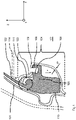
- figure 1 shows (viewed from the vehicle interior) a C-pillar 101 of a motor vehicle, which is otherwise not shown.
- a coordinate system is specified as a reference for directional information, as well as “front”, “back”, “above”, “below”, “right” and “left”, in which x is in a vehicle longitudinal direction forwards, z in a vehicle vertical axis upwards and y point in a vehicle lateral direction.
- a C-pillar garnish 102 is attached to a C-pillar 101 .
- the C-pillar is a final pillar of an otherwise unillustrated motor vehicle.
- the C-pillar 101 connects a basic structure to a roof structure, it is designed to be correspondingly stable and a high load can be introduced into the C-pillar.
- the C-pillar trim 102 is attached to the C-pillar 101 by suitable fastening means, not shown, such as clip connections, clamps, screws and combinations thereof.
- the C-pillar trim 102 lies flat on the C-pillar 101 and therefore there is sufficient space and opportunity to create a very stable connection by appropriately arranging fastening means. In this case, the fastening means can be hidden by the C-pillar trim 102 . Accordingly, the C-pillar trim 102 can withstand a high mechanical load.
- a console 103 adjoining the C-pillar trim 102 cannot withstand a high load.
- the console 103 is formed from thermoplastic material and has a wall thickness w of 1 mm to 5 mm, in particular 1.5 to 2.5 mm.
- a lamp, not shown, can be arranged in the console 103 .
- the console 103 serves in particular to conceal elements present in this area. To compensate for shape and position tolerances, the bracket 103 must have a certain flexibility, so that it cannot be reinforced at will.
- the console 103 is attached to the C-pillar 101 by means of fastening means that are less resilient and are also not shown. In an overlapping area 104, the console 103 overlaps the C-pillar trim 102 and at least partially covers it in this area. When the motor vehicle is ready for operation and the tailgate is closed (not shown), the C-pillar trim 102 and the console 103 are usually spatially separated from one another. The separation is made by a luggage cover 114.
- An extension 106 extends in one piece from the C-pillar trim 102 in a connection region 105 towards a vehicle interior 107, counter to the vehicle transverse direction y.
- a bag hook 108 is integrally formed on the extension 106 .
- the bag hook 108 can carry a load F on the order of up to 30 kg.
- a tab 109 formed on the console 103 covers the bag hook 108. A user does not recognize the bag hook 108.
- the tab 109 can be used as usual for hanging bags and the like, but the load F is not introduced into the thin-walled console 103, but into the bag hook 108 underneath on the much more stable C-pillar paneling 102.
- the C-pillar trim 102 is subjected to a tensile load.
- the extension 106 has a leverage effect that introduces a resulting moment M into the C-pillar trim 102 .
- the C-pillar trim extends to a support area 110.
- the C-pillar trim 102 is in contact with a stable section of a vehicle body.
- the vehicle body portion may be an inner skin of a metal double skin body and may be seamless or welded to the C-pillar 101 .
- reinforcing ribs 111 are formed on it in the area in which the moment M acts.
- the reinforcing ribs 111 nestle against an inner contour of the bracket 103 from the inside in the assembled state.
- the reinforcing ribs 111 extend out of the C-pillar trim 102 in the vehicle vertical axis z.
- the reinforcing ribs 111 are connected to the C-pillar trim 102 in one piece.
- the C-pillar trim 102 can be an injection molded part made of fiber-reinforced thermoplastics.
- FIG 2 shows a section through the bag hook 108 with the strap 109 surrounding it. It can be seen that a cavity 112 for receiving the bag hook 108 is formed in the strap 109 . A channel 113 can also be seen, into which a pocket flap (not shown) of a pocket can be inserted in order to hang up the pocket.
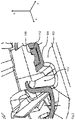
- FIG 3 A portion of the C-pillar trim 102 is shown with a bag hook 108 extending from the C-pillar trim 102 at the end of an extension 106 .
- the extension 106 is designed as a hollow profile 115 in the connection area 105 .
- the hollow profile 115 increases the resilience of the bag hook 108.
- a free space 116 extends in the area in which the tab is inserted when the bracket 103 is mounted, below the channel 113 (see figure 2 ).
- the free space 116 is correspondingly shaped geometrically to correspond to the channel 113 in order to accommodate it. In the installed state, the channel 116 fits snugly against the free space 116, encompassing the shape.
Landscapes
- Engineering & Computer Science (AREA)
- Mechanical Engineering (AREA)
- Vehicle Interior And Exterior Ornaments, Soundproofing, And Insulation (AREA)
Description
- Die Offenbarung bezieht sich auf einen Taschenhaken im Bereich einer C-Säulenverkleidung eines Kraftfahrzeugs. Eine C-Säule ist eine Strebe zwischen einer Grundstruktur einer Karosserie eines Kraftfahrzeuges und einem Dach des Kraftfahrzeuges. Insbesondere ist die C-Säule eine von vorne gezählt dritte Säule. Sollten vier Säulen vorhanden sein ist die C-Säule die letzte Säule im Heckbereich des Kraftfahrzeugs. Heutzutage sind Karosseriestrukturen in nahezu jeder Preiskategorie im Fahrgastraum zur Kaschierung, Geräuschdämmung und Sicherheit mit passenden Verkleidungsteilen verkleidet. Allerdings werden für einige Verkleidungsteile in der Regel leichte Werkstoffe verwendet, die nahezu beliebige geometrische Strukturen annehmen können, die jedoch nicht immer mechanischen Belastungen standhalten. Bringt man einen Taschenhaken an einer solchen Verkleidung an, so verformt sich dieser unter Last, gegebenenfalls erst nach einem längeren Zeitraum und gegebenenfalls auch nur unter Temperatureinwirkung. Die Verformungen führen dazu, dass Spaltmaße zwischen benachbarten Verkleidungsteilen entstehen oder die Verkleidungsteile während der Fahrt geräuschvoll aneinander reiben.
- Um dem entgegenzuwirken, wird in
CN204415264 vorgeschlagen, einen Taschenhaken über ein stabiles Winkelstück an der Karosserie (Außen- oder Innenhaut) zu befestigen. Eine auf den Taschenhaken wirkende Last wird somit nicht in das Verkleidungsteil bzw. die C-Säulenverkleidung eingeleitet, sondern in die Karosserie. Das Verkleidungsteil bzw. die C-Säulenverkleidung verformen sich unter Last nicht. -
JP 2015074329A - Diese Nachteile werden mit den Merkmalen des Anspruchs 1 abgestellt. Die Unteransprüche sind in technologisch sinnvoller Weise miteinander kombinierbar und sie zeigen jeweils weitere Ausgestaltungen auf. Vorgesehen ist demgemäß eine C-Säulenanordnung eines Kraftfahrzeuges, mit den Merkmalen des Anspruchs 1.
- Die Befestigung der C-Säulenverkleidung mit der C-Säule kann über Clip- und Schraubverbindungen erfolgen. Die C-Säulenverkleidung kann einen im wesentlichen flächigen Abschnitt aufweisen, der sich zwischen der Konsole, einem hinteren Einstieg oder Heckfenster, einer Heckklappe und einem Dachhimmel erstreckt. Am hinteren Einstieg bzw. am Heckfenster ist die C-Säulenverkleidung in der Regel mit einer Dichtung eingeklemmt. Man kann sich zunutze machen, dass die C-Säulenverkleidung zumindest in der zur Erdbeschleunigung parallelen Fahrzeughochachse Z eine hohe Zugkraft aufnehmen kann. Allerdings soll der Taschenhaken unter einer Gepäckabdeckung im Kofferraum liegen. Die Gepäckabdeckung bildet einen Abschluss zwischen dem Ladegut im Kofferraum und dem Fahrzeuginnenraum, bei geöffneter Heckklappe öffnet sich die Heckabdeckung in der Regel mit (geführt über die Heckklappe). Dementsprechend soll ein Haken unterhalb der Heckabdeckung an der Konsole angeordnet werden. Von der Belastungsfähigkeit der C-Säule konnte dementsprechend nicht profitiert werden. Hiervon ausgehend wird vorgeschlagen, die C-Säule bis in den Überlappungsbereich nach unten entgegen der Z-Richtung fortzusetzen und hieran einen Taschenhaken auszubilden. Die Konsole liegt darüber und der Nutzer verwendet den Taschenhaken wie gewohnt. Allerdings kann der Taschenhaken eine ungleich viel höhere Last aufnehmen, ohne dass sich die Konsole verformt, da die Last in den nach unten fortgesetzten Überlappungsbereich an der C-Säulenverkleidung eingeleitet wird.
- Eine Konsole ist ein Bauteil, das neben der reinen Verkleidung der Karosserie weitere Funktionen übernimmt. Beispielsweise ist in der Konsole häufig ein Lüftungsgitter integriert, welches Luft aus dem Innenraum aus ein einen Bereich zwischen der Konsole und der Fahrzeugkarosserie hindurchlässt. Die Konsole kann elektrische Anschlüsse und Signalanschlüsse für Antennenmodule, Lichtmodule und dergleichen beinhalten und in einigen Ausführungen als Träger für Sicherungen und elektrische Komponenten dienen. Die Konsole ist nicht einstückig mit der C-Säulenverkleidung verbunden, sondern darunter angeordnet. Zwischen der Konsole und der C-Säulenverkleidung ist ein Spalt, der möglichst klein zu halten ist. Indem eine am Taschenhaken angeordnete Last in die C-Säulenverkleidung eingeleitet wird, führt die Last nicht zu einer Verformung der Konsole oder zu einem Auseinanderziehen des Spaltes zwischen der C-Säulenverkleidung und der Konsole.
- Konsolen der oben genannten Art werden häufig im Spritzgussverfahren hergestellt. Die Lasche ist im Prinzip ein Hinterschnitt, d.h. zwei transversal bewegte Werkzeugkavitäten können diesen nicht ohne zusätzliche Maßnahmen entformen. Als Maßnahme könnte ein Formkern eingelegt werden. Üblicher und kostengünstiger ist es, dass statt eines Hinterschnitts im Bereich der Lasche eine gegenüberliegende Öffnung vorgesehen ist, in die im Spritzgussverfahren ein Fortsatz eindringt und die Lasche von innen ausformt. Als zusätzlicher Vorteil der offenbarungsgemäßen C-Säulenanordnung kann diese Öffnung durch den Fortsatz an der C-Säulenverkleidung geschlossen werden.
- An der Konsole ist im Überlappungsbereich eine Lasche angeordnet, welche sich einstückig aus der Konsole erstreckt und auf einer vom Fahrzeuginnenraum weg weisenden Seite eine Kavität aufweist, in welcher der Taschenhaken in einer Einbaulage angeordnet ist, so dass der Taschenhaken vom Fahrzeuginnenraum her nicht sichtbar ist.
- Der die Last aufnehmende Taschenhaken ist durch die Lasche verdeckt und nicht sichtbar. An der Lasche können Taschen aufgehängt werden, deren Belastung in den Taschenhaken eingeleitet wird.
- Dadurch dass der Taschenhaken die Kavität in einem unbelasteten Zustand, in welchem keine Belastung auf den Taschenhaken wirkt, nicht berührt, wird vermieden, dass die Konsole durch den Taschenhaken verformt bzw. zum Fahrzeuginnenraum hin gedrückt wird. Wenn eine Tasche an den Taschenhaken gehängt wird, verformt sich zwar bei entsprechender Belastung die Lasche sowie benachbarte Bereiche der Konsole, diese werden aber größtenteils von den Haltelaschen der Tasche verdeckt.
- Entsprechend einer weiteren Ausgestaltung ist die Konsole aus Kunststoff gefertigt und weist zumindest im Überlappungsbereich eine Wandstärke von 1 mm bis 5 mm, insbesondere von 1,5 bis 2,5 mm auf.
- Die Konsole ist demnach verhältnismäßig dünnwandig. Demensprechend gering ist die Belastbarkeit der Konsole. Die Konsole ist dazu ausgestaltet, Form- und Lagetoleranzen in gewissem Maße auszugleichen, weshalb die geringe Belastbarkeit gewollt ist. Die vorliegende Offenbarung zielt darauf ab, die Konsole von innen so auszusteifen, dass eine Tasche mit einem Gewicht von ca. 5 kg daran angehängt werden kann. Die Aussteifung erfolgt wie oben ausgeführt durch den Taschenhaken, der an der C-Säulenverkleidung angeordnet ist.
- In einer weiteren Ausgestaltung weist die C-Säulenverkleidung im von der Konsole verdeckten Überlappungsbereich parallele, sich bis in eine Innenkontur der Konsole im Überlappungsbereich erstreckende Verstärkungsrippen auf.
- Die C-Säulenverkleidung erstreckt sich im Überlappungsbereich zum Fahrzeuginnenraum hin. Die Erstreckung bewirkt eine Hebelwirkung. Bei Belastung wird die C-Säulenverkleidung demnach verformt. Die Verformung wird durch die Verstärkungsrippen reduziert.
- In einer Ausgestaltung ist der Fortsatz an einem Verbindungsbereich, in welchem er sich aus der C-Säulenverkleidung erstreckt, als geschlossenes Hohlprofil ausgebildet, wobei zwischen dem geschlossenen Hohlprofil und dem Taschenhaken ein Freiraum zur Aufnahme einer Taschenlasche ausgebildet ist.
- Die hierin beschriebenen Zeichnungen dienen nur zu Veranschaulichungszwecken und sollen den Umfang der vorliegenden Offenbarung in keiner Weise einschränken. Es zeigen:
-
Fig. 1 eine C-Säule mit einer C-Säulenverkleidung und einer daran angrenzenden Konsole; -
Fig. 2 eine teilweise geschnittene Darstellung des Taschenhakens bzw. der Konsole; und -
Fig. 3 eine Darstellung eines Fortsatzes an der C-Säulenverkleidung, mit einem Hohlprofil und Verstärkungsrippen zur Erreichung einer hohen Steifigkeit des Taschenhakens sowie den Taschenhaken selbst. - Die folgende Beschreibung ist dem Wesen nach lediglich veranschaulichend. Der Klarheit halber sind in den Zeichnungen zur Bezeichnung ähnlicher Elemente dieselben Bezugszeichen verwendet.
-
Figur 1 zeigt (vom Fahrzeuginnenraum betrachtet) eine C-Säule 101 eines ansonsten nicht dargestellten Kraftfahrzeuges. Als Referenzen für Richtungsangaben, sowie "vorne", "hinten", "oben", "unten", "rechts" und "links" ist ein Koordinatensystem angegeben, bei dem x in eine Fahrzeuglängsrichtung nach vorne, z in eine Fahrzeughochachse nach oben und y in eine Fahrzeugquerrichtung weisen. - An einer C-Säule 101 ist ein C-Säulenverkleidung 102 angebracht. Die C-Säule ist eine letzte Säule eines ansonsten nicht dargestellten Kraftfahrzeugs. Die C-Säule 101 verbindet eine Grundstruktur mit einer Dachstruktur, dementsprechend stabil ist sie ausgeführt und es kann eine hohe Belastung in die C-Säule eingeleitet werden. Die Anbringung der C-Säulenverkleidung 102 an der C-Säule 101 erfolgt durch geeignete, nicht dargestellte Befestigungsmittel wie Clipverbindungen, Klemmen, Schrauben und Kombinationen daraus. Die C-Säulenverkleidung 102 liegt flächig auf der C-Säule 101 und somit steht ausreichend Platz und Gelegenheit zur Verfügung, um eine sehr stabile Verbindung durch entsprechende Anordnung von Befestigungsmitteln zu schaffen. Die Befestigungsmittel können dabei durch die C-Säulenverkleidung 102 verborgen werden. Die C-Säulenverkleidung 102 kann dementsprechend einer hohen mechanischen Belastung standhalten.
- Einer hohen Belastung hält eine an die C-Säulenverkleidung 102 angrenzende Konsole 103 hingegen nicht stand. Die Konsole 103 ist aus thermoplastischem Kunststoff geformt und besitzt eine Wandstärke w von 1 mm bis 5 mm, insbesondere von 1,5 bis 2,5 mm auf. In der Konsole 103 kann eine nicht dargestellte Leuchte angeordnet sein. Die Konsole 103 dient insbesondere dazu, in diesem Bereich vorhandene Elemente zu kaschieren. Zum Ausgleich von Form- und Lagetoleranzen muss die Konsole 103 eine gewisse Flexibilität aufweisen, so dass sie auch nicht beliebig verstärkt werden kann.
- Die Konsole 103 ist über weniger belastbare, ebenfalls nicht dargestellte Befestigungsmittel an der C-Säule 101 angebracht. In einem Überlappungsbereich 104 überlappt die Konsole 103 die C-Säulenverkleidung 102 und verdeckt diese zumindest teilweise in diesem Bereich. Üblicherweise sind im betriebsbereiten Zustand des Kraftfahrzeuges bei geschlossener (nicht dargestellter) Heckklappe die C-Säulenverkleidung 102 und die Konsole 103 räumlich voneinander getrennt. Die Trennung erfolgt durch eine Gepäckabdeckung 114.
- Aus der C-Säulenverkleidung 102 erstreckt sich einstückig in einem Verbindungsbereich 105 ein Fortsatz 106 zu einem Fahrzeuginnenraum 107 hin, entgegen der Fahrzeugquerrichtung y. An dem Fortsatz 106 ist ein Taschenhaken 108 einstückig angeformt. Der Taschenhaken 108 kann eine Belastung F in der Größenordnung von bis zu 30 kg tragen. Eine an der Konsole 103 angeformte Lasche 109 verdeckt den Taschenhaken 108. Ein Anwender erkennt den Taschenhaken 108 nicht. Die Lasche 109 kann wie gewohnt zum Anhängen von Taschen und der gleichen verwendet werden, die Belastung F wird jedoch nicht in die dünnwandige Konsole 103 eingeleitet, sondern in den darunter liegenden Taschenhaken 108 an der viel stabileren C-Säulenverkleidung 102.
- Die C-Säulenverkleidung 102 wird hierdurch auf Zug belastet. Zudem wirkt der Fortsatz 106 eine Hebelwirkung, die ein resultierendes Moment M in die C-Säulenverkleidung 102 einleitet. Um dieses Moment M abzustützen, erstreckt sich die C-Säulenverkleidung bis zu einem Stützbereich 110. In dem Stützbereich 110 liegt die C-Säulenverkleidung 102 an einem stabilen Abschnitt einer Fahrzeugkarosserie an. Der Abschnitt der Fahrzeugkarosserie kann eine Innenhaut einer doppelwandigen Karosserie aus Metall sein und nahtlos in die C-Säule 101 übergehen oder mit dieser verschweißt sein.
- Als weitere Maßnahme zur Stabilisierung der C-Säulenverkleidung 102 sind an ihr in dem Bereich, in dem das Moment M wirkt, Verstärkungsrippen 111 angeformt. Die Verstärkungsrippen 111 schmiegen sich im montierten Zustand von innen an eine Innenkontur der Konsole 103 an. Die Verstärkungsrippen 111 erstrecken sich in der Fahrzeughochachse z aus der C-Säulenverkleidung 102. Die Verstärkungsrippen 111 sind einstückig mit der C-Säulenverkleidung 102 verbunden. Bei der C-Säulenverkleidung 102 kann es sich um ein Spritzgussteil aus faserverstärkten Thermoplasten handeln.
-
Figur 2 zeigt einen Schnitt durch den Taschenhaken 108 mit der ihn umgebenden Lasche 109. Man erkennt, dass in der Lasche 109 eine Kavität 112 zur Aufnahme des Taschenhakens 108 angeformt ist. Man erkennt weiterhin eine Rinne 113, in welche eine nicht dargestellte Taschenlasche einer Tasche eingelegt werden kann, um die Tasche aufzuhängen. - In
Figur 3 ist ein Bereich der C-Säulenverkleidung 102 dargestellt, mit einem Taschenhaken 108, der sich am Ende eines Fortsatzes 106 aus der C-Säulenverkleidung 102 erstreckt. Man erkennt, dass der Fortsatz 106 in dem Verbindungsbereich 105 als Hohlprofil 115 ausgebildet ist. Das Hohlprofil 115 erhöht die Belastbarkeit des Taschenhakens 108. Ein Freiraum 116 erstreckt sich in dem Bereich, in dem bei montierter Konsole 103 die Lasche eingelegt wird, unterhalb der Rinne 113 (sieheFigur 2 ). Der Freiraum 116 ist dementsprechend geometrisch korrespondierend zu der Rinne 113 ausgeformt, um diese in sich aufzunehmen. Im montierten Zustand schmiegt sich die Rinne 116 formumgreifend an den Freiraum 116 an. - Gleichwohl zumindest ein Ausführungsbeispiel in der vorangegangenen Beschreibung sowie der Figurenbeschreibung dargestellt wurde, sollte man anerkennen, dass eine hohe Anzahl an Variationen existieren. Weiterhin sollte man anerkennen, dass das Ausführungsbeispiel bzw. die Ausführungsbeispiele nur Beispiele sind und dass sie nicht dazu dienen, den Schutzbereich, die Anwendbarkeit oder die genaue Ausgestaltung in irgendeiner Art und Weise zu beschränken. Vielmehr stellen die Beschreibung sowie die Figurenbeschreibung für den Fachmann eine nützliche Anleitung zur Implementierung mindestens einer Ausführungsform bereit, dabei sollte klar sein, dass verschiedene Änderungen in der Form und Funktion der beschriebenen Merkmale vorgenommen werden können, ohne den Schutzbereich der Ansprüche und deren Äquivalente zu verlassen. Die C-Säulenverkleidung kann beispielsweise auch an anderen Positionen im Kraftfahrzeug anspruchsgemäß verwendet werden.
-
- 101
- C-Säule
- 102
- C-Säulenverkleidung
- 103
- Konsole
- 104
- Überlappungsbereich
- 105
- Verbindungsbereich
- 106
- Fortsatz
- 107
- Fahrzeuginnenraum
- 108
- Taschenhaken
- 109
- Lasche
- 110
- Stützbereich
- 111
- Verstärkungsrippen
- 112
- Kavität
- 113
- Rinne
- 114
- Gepäckabdeckung
- 115
- Hohlprofil
- 116
- Freiraum
- F
- Belastung
- M
- Moment
- w
- Wandstärke
- x
- Fahrzeuglängsrichtung
- y
- Fahrzeugquerrichtung
- z
- Fahrzeughochachse
Claims (5)
- C-Säulenanordnung eines Kraftfahrzeuges,- mit einer C-Säule (101) des Kraftfahrzeuges,- mit einer C-Säulenverkleidung (102), welche an der C-Säule (101) des Kraftfahrzeuges befestigt ist und die C-Säule (101) flächig abdeckt,- mit einer Konsole (103), welche in einen Überlappungsbereich (104) der C-Säulenverkleidung (102) überlappt,- wobei sich im Überlappungsbereich (104) ein Taschenhaken (108) aus der C-Säulenverkleidung (102) erstreckt und einstückig mit dieser verbunden ist, so dass eine am Taschenhaken (108) eingeleitete Belastung (F) in die C-Säulenverkleidung (102) eingeleitet wird- wobei an der Konsole (103) im Überlappungsbereich (104) eine Lasche (109) angeordnet ist, welche sich einstückig aus der Konsole (103) erstreckt und auf einer vom Fahrzeuginnenraum (107) weg weisenden Seite eine Kavität (112) aufweist, in welcher der Taschenhaken (108) in einer Einbaulage angeordnet ist, so dass der Taschenhaken (108) vom Fahrzeuginnenraum (107) her nicht sichtbar ist, dadurch gekennzeichnet, dass eine am Taschenhaken (108) eingeleitete Belastung (F) nicht in die Konsole (103) eingeleitet wird, und dass der Taschenhaken (108) die Kavität (112) in einem unbelasteten Zustand, in welchem keine Belastung (F) auf den Taschenhaken (108) wirkt, nicht berührt.
- C-Säulenanordnung nach einem der vorhergehenden Ansprüche, wobei die Konsole (103) aus Kunststoff gefertigt ist und zumindest im Überlappungsbereich (104) eine Wandstärke (w) von 1 mm bis 5 mm, insbesondere von 1,5 bis 2,5 mm aufweist.
- C-Säulenanordnung nach einem der vorhergehen Ansprüche, wobei die C-Säulenverkleidung (102) im von der Konsole (103) verdeckten Überlappungsbereich (104) parallele, sich bis zu einer Innenkontur der Konsole im Überlappungsbereich (104) erstreckende Verstärkungsrippen (111) aufweist.
- C-Säulenanordnung nach einem der vorhergehenden Ansprüche, wobei der Taschenhaken (108) an einem sich in einer Fahrzeugquerrichtung (y) zum Fahrzeuginnenraum (107) erstreckendem Fortsatz (106) angeformt ist.
- C-Säulenanordnung nach Anspruch 4, wobei der Fortsatz (106) an einem Verbindungsbereich (105), in welchem er sich aus der C-Säulenverkleidung (102) erstreckt, als geschlossenes Hohlprofil (115) ausgebildet ist, wobei zwischen dem geschlossenen Hohlprofil (115) und dem Taschenhaken (108) ein Freiraum (116) zur Aufnahme einer Taschenlasche ausgebildet ist.
Applications Claiming Priority (2)
| Application Number | Priority Date | Filing Date | Title |
|---|---|---|---|
| DE102019201579.4A DE102019201579B3 (de) | 2019-02-07 | 2019-02-07 | Taschenhaken für den Heckbereich eines Kraftfahrzeuges |
| PCT/EP2019/084812 WO2020160818A1 (de) | 2019-02-07 | 2019-12-12 | Taschenhaken für den heckbereich eines kraftfahrzeuges |
Publications (2)
| Publication Number | Publication Date |
|---|---|
| EP3921207A1 EP3921207A1 (de) | 2021-12-15 |
| EP3921207B1 true EP3921207B1 (de) | 2022-11-02 |
Family
ID=69156358
Family Applications (1)
| Application Number | Title | Priority Date | Filing Date |
|---|---|---|---|
| EP19835255.1A Active EP3921207B1 (de) | 2019-02-07 | 2019-12-12 | Taschenhaken für den heckbereich eines kraftfahrzeuges |
Country Status (4)
| Country | Link |
|---|---|
| EP (1) | EP3921207B1 (de) |
| DE (1) | DE102019201579B3 (de) |
| MA (1) | MA56422A (de) |
| WO (1) | WO2020160818A1 (de) |
Family Cites Families (4)
| Publication number | Priority date | Publication date | Assignee | Title |
|---|---|---|---|---|
| GB2454929B (en) * | 2007-11-26 | 2012-02-22 | Nissan Motor Mfg Uk Ltd | Improvements in or relating to luggage restraints |
| JP5190785B2 (ja) * | 2008-08-26 | 2013-04-24 | スズキ株式会社 | トリムのフック周辺部の構造 |
| JP2015074329A (ja) * | 2013-10-09 | 2015-04-20 | 河西工業株式会社 | 車両用内装部品 |
| CN204415264U (zh) * | 2015-01-05 | 2015-06-24 | 四川汽车工业股份有限公司 | 一种suv车型后备箱的集成式挂物固定结构 |
-
2019
- 2019-02-07 DE DE102019201579.4A patent/DE102019201579B3/de not_active Expired - Fee Related
- 2019-12-12 WO PCT/EP2019/084812 patent/WO2020160818A1/de not_active Ceased
- 2019-12-12 EP EP19835255.1A patent/EP3921207B1/de active Active
- 2019-12-12 MA MA056422A patent/MA56422A/fr unknown
Also Published As
| Publication number | Publication date |
|---|---|
| MA56422A (fr) | 2022-05-11 |
| DE102019201579B3 (de) | 2020-03-19 |
| WO2020160818A1 (de) | 2020-08-13 |
| EP3921207A1 (de) | 2021-12-15 |
Similar Documents
| Publication | Publication Date | Title |
|---|---|---|
| EP1914097B1 (de) | Rahmen für ein Kraftfahrzeugdach | |
| EP1373053B1 (de) | Vorrichtung zur verstärkung eines hohlteils eines fahrzeugs | |
| EP1288109B1 (de) | Kraftfahrzeug mit einem in einem Fahrzeugendbereich angeordneten Aufnahmeraum | |
| DE102010024737A1 (de) | Fahrzeugkarosserie | |
| DE60221862T2 (de) | Stufenheck-kraftfahrzeug | |
| EP1184266A3 (de) | Aufbau für ein Kraftfahrzeug | |
| EP2492123B1 (de) | Fensterelement für eine Seitentür, insbesondere eine hintere Seitentür, eines Kraftwagens | |
| EP1275540A2 (de) | Kraftfahrzeugtür mit Verstärkungsteil im Türmodul und im Türmodul integrierter Brüstung | |
| DE102008009088B4 (de) | Karosserie eines Kraftfahrzeugs mit einem Seitenschweller | |
| DE10254348B4 (de) | Baugruppe für einen Cockpit-Bereich | |
| EP2399805A2 (de) | Hintere Fahrzeugkarosserie | |
| EP3921207B1 (de) | Taschenhaken für den heckbereich eines kraftfahrzeuges | |
| DE102007014391A1 (de) | Seitenaufprallschutzeinrichtung, die zwischen Innen- und Außenbleche eingebaut ist | |
| EP3837126A1 (de) | Dachmodul für ein fahrzeugdach eines personenkraftwagens | |
| DE102005014570A1 (de) | Fahrzeugtür für ein Nutzfahrzeug | |
| DE202015008710U1 (de) | Kraftfahrzeug mit einer Vorrichtung zur Befestigung eines Warndreieckes | |
| DE102011105371B4 (de) | Selbsttragende Karosserie für ein Fahrzeug, insbesondere für ein Kraftfahrzeug | |
| DE102015202420B4 (de) | Türinnenverkleidung, Fahrzeugtür mit einer Türinnenverkleidung sowie Fahrzeug mit einer Fahrzeugtür | |
| DE102009002777B4 (de) | Versteifungsstrebe | |
| DE10126218A1 (de) | Türaufprallträger-Modul und Kraftfahrzeugtür | |
| EP1258390A1 (de) | Sitzlehneneinrichtung für ein Kraftfahrzeug | |
| DE19821076A1 (de) | Fahrzeugkarosserie mit wenigstens einer Fahrzeugtür | |
| DE102007052720A1 (de) | Modulträger für ein Fahrzeugarmaturenbrett | |
| DE102010010477B4 (de) | Versteifungsstruktur | |
| DE10260795A1 (de) | Karosseriesäule eines Personenkraftwagens |
Legal Events
| Date | Code | Title | Description |
|---|---|---|---|
| STAA | Information on the status of an ep patent application or granted ep patent |
Free format text: STATUS: UNKNOWN |
|
| STAA | Information on the status of an ep patent application or granted ep patent |
Free format text: STATUS: THE INTERNATIONAL PUBLICATION HAS BEEN MADE |
|
| PUAI | Public reference made under article 153(3) epc to a published international application that has entered the european phase |
Free format text: ORIGINAL CODE: 0009012 |
|
| STAA | Information on the status of an ep patent application or granted ep patent |
Free format text: STATUS: REQUEST FOR EXAMINATION WAS MADE |
|
| 17P | Request for examination filed |
Effective date: 20210629 |
|
| AK | Designated contracting states |
Kind code of ref document: A1 Designated state(s): AL AT BE BG CH CY CZ DE DK EE ES FI FR GB GR HR HU IE IS IT LI LT LU LV MC MK MT NL NO PL PT RO RS SE SI SK SM TR |
|
| DAX | Request for extension of the european patent (deleted) | ||
| RAV | Requested validation state of the european patent: fee paid |
Extension state: MA Effective date: 20210629 |
|
| GRAP | Despatch of communication of intention to grant a patent |
Free format text: ORIGINAL CODE: EPIDOSNIGR1 |
|
| STAA | Information on the status of an ep patent application or granted ep patent |
Free format text: STATUS: GRANT OF PATENT IS INTENDED |
|
| INTG | Intention to grant announced |
Effective date: 20220609 |
|
| GRAS | Grant fee paid |
Free format text: ORIGINAL CODE: EPIDOSNIGR3 |
|
| GRAA | (expected) grant |
Free format text: ORIGINAL CODE: 0009210 |
|
| STAA | Information on the status of an ep patent application or granted ep patent |
Free format text: STATUS: THE PATENT HAS BEEN GRANTED |
|
| AK | Designated contracting states |
Kind code of ref document: B1 Designated state(s): AL AT BE BG CH CY CZ DE DK EE ES FI FR GB GR HR HU IE IS IT LI LT LU LV MC MK MT NL NO PL PT RO RS SE SI SK SM TR |
|
| REG | Reference to a national code |
Ref country code: GB Ref legal event code: FG4D Free format text: NOT ENGLISH |
|
| REG | Reference to a national code |
Ref country code: DE Ref legal event code: R084 Ref document number: 502019006177 Country of ref document: DE |
|
| REG | Reference to a national code |
Ref country code: CH Ref legal event code: EP Ref country code: AT Ref legal event code: REF Ref document number: 1528546 Country of ref document: AT Kind code of ref document: T Effective date: 20221115 |
|
| REG | Reference to a national code |
Ref country code: DE Ref legal event code: R096 Ref document number: 502019006177 Country of ref document: DE |
|
| REG | Reference to a national code |
Ref country code: IE Ref legal event code: FG4D Free format text: LANGUAGE OF EP DOCUMENT: GERMAN |
|
| REG | Reference to a national code |
Ref country code: GB Ref legal event code: 746 Effective date: 20221206 |
|
| REG | Reference to a national code |
Ref country code: LT Ref legal event code: MG9D |
|
| REG | Reference to a national code |
Ref country code: NL Ref legal event code: MP Effective date: 20221102 |
|
| PG25 | Lapsed in a contracting state [announced via postgrant information from national office to epo] |
Ref country code: SE Free format text: LAPSE BECAUSE OF FAILURE TO SUBMIT A TRANSLATION OF THE DESCRIPTION OR TO PAY THE FEE WITHIN THE PRESCRIBED TIME-LIMIT Effective date: 20221102 Ref country code: PT Free format text: LAPSE BECAUSE OF FAILURE TO SUBMIT A TRANSLATION OF THE DESCRIPTION OR TO PAY THE FEE WITHIN THE PRESCRIBED TIME-LIMIT Effective date: 20230302 Ref country code: NO Free format text: LAPSE BECAUSE OF FAILURE TO SUBMIT A TRANSLATION OF THE DESCRIPTION OR TO PAY THE FEE WITHIN THE PRESCRIBED TIME-LIMIT Effective date: 20230202 Ref country code: LT Free format text: LAPSE BECAUSE OF FAILURE TO SUBMIT A TRANSLATION OF THE DESCRIPTION OR TO PAY THE FEE WITHIN THE PRESCRIBED TIME-LIMIT Effective date: 20221102 Ref country code: FI Free format text: LAPSE BECAUSE OF FAILURE TO SUBMIT A TRANSLATION OF THE DESCRIPTION OR TO PAY THE FEE WITHIN THE PRESCRIBED TIME-LIMIT Effective date: 20221102 Ref country code: ES Free format text: LAPSE BECAUSE OF FAILURE TO SUBMIT A TRANSLATION OF THE DESCRIPTION OR TO PAY THE FEE WITHIN THE PRESCRIBED TIME-LIMIT Effective date: 20221102 |
|
| PG25 | Lapsed in a contracting state [announced via postgrant information from national office to epo] |
Ref country code: RS Free format text: LAPSE BECAUSE OF FAILURE TO SUBMIT A TRANSLATION OF THE DESCRIPTION OR TO PAY THE FEE WITHIN THE PRESCRIBED TIME-LIMIT Effective date: 20221102 Ref country code: PL Free format text: LAPSE BECAUSE OF FAILURE TO SUBMIT A TRANSLATION OF THE DESCRIPTION OR TO PAY THE FEE WITHIN THE PRESCRIBED TIME-LIMIT Effective date: 20221102 Ref country code: LV Free format text: LAPSE BECAUSE OF FAILURE TO SUBMIT A TRANSLATION OF THE DESCRIPTION OR TO PAY THE FEE WITHIN THE PRESCRIBED TIME-LIMIT Effective date: 20221102 Ref country code: IS Free format text: LAPSE BECAUSE OF FAILURE TO SUBMIT A TRANSLATION OF THE DESCRIPTION OR TO PAY THE FEE WITHIN THE PRESCRIBED TIME-LIMIT Effective date: 20230302 Ref country code: HR Free format text: LAPSE BECAUSE OF FAILURE TO SUBMIT A TRANSLATION OF THE DESCRIPTION OR TO PAY THE FEE WITHIN THE PRESCRIBED TIME-LIMIT Effective date: 20221102 Ref country code: GR Free format text: LAPSE BECAUSE OF FAILURE TO SUBMIT A TRANSLATION OF THE DESCRIPTION OR TO PAY THE FEE WITHIN THE PRESCRIBED TIME-LIMIT Effective date: 20230203 |
|
| PG25 | Lapsed in a contracting state [announced via postgrant information from national office to epo] |
Ref country code: NL Free format text: LAPSE BECAUSE OF FAILURE TO SUBMIT A TRANSLATION OF THE DESCRIPTION OR TO PAY THE FEE WITHIN THE PRESCRIBED TIME-LIMIT Effective date: 20221102 |
|
| PG25 | Lapsed in a contracting state [announced via postgrant information from national office to epo] |
Ref country code: SM Free format text: LAPSE BECAUSE OF FAILURE TO SUBMIT A TRANSLATION OF THE DESCRIPTION OR TO PAY THE FEE WITHIN THE PRESCRIBED TIME-LIMIT Effective date: 20221102 Ref country code: RO Free format text: LAPSE BECAUSE OF FAILURE TO SUBMIT A TRANSLATION OF THE DESCRIPTION OR TO PAY THE FEE WITHIN THE PRESCRIBED TIME-LIMIT Effective date: 20221102 Ref country code: EE Free format text: LAPSE BECAUSE OF FAILURE TO SUBMIT A TRANSLATION OF THE DESCRIPTION OR TO PAY THE FEE WITHIN THE PRESCRIBED TIME-LIMIT Effective date: 20221102 Ref country code: DK Free format text: LAPSE BECAUSE OF FAILURE TO SUBMIT A TRANSLATION OF THE DESCRIPTION OR TO PAY THE FEE WITHIN THE PRESCRIBED TIME-LIMIT Effective date: 20221102 Ref country code: CZ Free format text: LAPSE BECAUSE OF FAILURE TO SUBMIT A TRANSLATION OF THE DESCRIPTION OR TO PAY THE FEE WITHIN THE PRESCRIBED TIME-LIMIT Effective date: 20221102 |
|
| REG | Reference to a national code |
Ref country code: CH Ref legal event code: PL |
|
| REG | Reference to a national code |
Ref country code: DE Ref legal event code: R097 Ref document number: 502019006177 Country of ref document: DE |
|
| REG | Reference to a national code |
Ref country code: BE Ref legal event code: MM Effective date: 20221231 |
|
| PG25 | Lapsed in a contracting state [announced via postgrant information from national office to epo] |
Ref country code: SK Free format text: LAPSE BECAUSE OF FAILURE TO SUBMIT A TRANSLATION OF THE DESCRIPTION OR TO PAY THE FEE WITHIN THE PRESCRIBED TIME-LIMIT Effective date: 20221102 Ref country code: LU Free format text: LAPSE BECAUSE OF NON-PAYMENT OF DUE FEES Effective date: 20221212 Ref country code: AL Free format text: LAPSE BECAUSE OF FAILURE TO SUBMIT A TRANSLATION OF THE DESCRIPTION OR TO PAY THE FEE WITHIN THE PRESCRIBED TIME-LIMIT Effective date: 20221102 |
|
| PLBE | No opposition filed within time limit |
Free format text: ORIGINAL CODE: 0009261 |
|
| STAA | Information on the status of an ep patent application or granted ep patent |
Free format text: STATUS: NO OPPOSITION FILED WITHIN TIME LIMIT |
|
| 26N | No opposition filed |
Effective date: 20230803 |
|
| PG25 | Lapsed in a contracting state [announced via postgrant information from national office to epo] |
Ref country code: LI Free format text: LAPSE BECAUSE OF NON-PAYMENT OF DUE FEES Effective date: 20221231 Ref country code: IE Free format text: LAPSE BECAUSE OF NON-PAYMENT OF DUE FEES Effective date: 20221212 Ref country code: CH Free format text: LAPSE BECAUSE OF NON-PAYMENT OF DUE FEES Effective date: 20221231 |
|
| PG25 | Lapsed in a contracting state [announced via postgrant information from national office to epo] |
Ref country code: SI Free format text: LAPSE BECAUSE OF FAILURE TO SUBMIT A TRANSLATION OF THE DESCRIPTION OR TO PAY THE FEE WITHIN THE PRESCRIBED TIME-LIMIT Effective date: 20221102 Ref country code: BE Free format text: LAPSE BECAUSE OF NON-PAYMENT OF DUE FEES Effective date: 20221231 |
|
| REG | Reference to a national code |
Ref country code: DE Ref legal event code: R081 Ref document number: 502019006177 Country of ref document: DE Owner name: STELLANTIS AUTO SAS, FR Free format text: FORMER OWNER: PSA AUTOMOBILES SA, POISSY, FR |
|
| PG25 | Lapsed in a contracting state [announced via postgrant information from national office to epo] |
Ref country code: CY Free format text: LAPSE BECAUSE OF FAILURE TO SUBMIT A TRANSLATION OF THE DESCRIPTION OR TO PAY THE FEE WITHIN THE PRESCRIBED TIME-LIMIT Effective date: 20221102 |
|
| PG25 | Lapsed in a contracting state [announced via postgrant information from national office to epo] |
Ref country code: MK Free format text: LAPSE BECAUSE OF FAILURE TO SUBMIT A TRANSLATION OF THE DESCRIPTION OR TO PAY THE FEE WITHIN THE PRESCRIBED TIME-LIMIT Effective date: 20221102 Ref country code: IT Free format text: LAPSE BECAUSE OF FAILURE TO SUBMIT A TRANSLATION OF THE DESCRIPTION OR TO PAY THE FEE WITHIN THE PRESCRIBED TIME-LIMIT Effective date: 20221102 Ref country code: HU Free format text: LAPSE BECAUSE OF FAILURE TO SUBMIT A TRANSLATION OF THE DESCRIPTION OR TO PAY THE FEE WITHIN THE PRESCRIBED TIME-LIMIT; INVALID AB INITIO Effective date: 20191212 |
|
| PG25 | Lapsed in a contracting state [announced via postgrant information from national office to epo] |
Ref country code: MC Free format text: LAPSE BECAUSE OF FAILURE TO SUBMIT A TRANSLATION OF THE DESCRIPTION OR TO PAY THE FEE WITHIN THE PRESCRIBED TIME-LIMIT Effective date: 20221102 |
|
| PG25 | Lapsed in a contracting state [announced via postgrant information from national office to epo] |
Ref country code: MC Free format text: LAPSE BECAUSE OF FAILURE TO SUBMIT A TRANSLATION OF THE DESCRIPTION OR TO PAY THE FEE WITHIN THE PRESCRIBED TIME-LIMIT Effective date: 20221102 |
|
| PG25 | Lapsed in a contracting state [announced via postgrant information from national office to epo] |
Ref country code: BG Free format text: LAPSE BECAUSE OF FAILURE TO SUBMIT A TRANSLATION OF THE DESCRIPTION OR TO PAY THE FEE WITHIN THE PRESCRIBED TIME-LIMIT Effective date: 20221102 |
|
| PG25 | Lapsed in a contracting state [announced via postgrant information from national office to epo] |
Ref country code: MT Free format text: LAPSE BECAUSE OF FAILURE TO SUBMIT A TRANSLATION OF THE DESCRIPTION OR TO PAY THE FEE WITHIN THE PRESCRIBED TIME-LIMIT Effective date: 20221102 |
|
| PGFP | Annual fee paid to national office [announced via postgrant information from national office to epo] |
Ref country code: DE Payment date: 20241121 Year of fee payment: 6 |
|
| PGFP | Annual fee paid to national office [announced via postgrant information from national office to epo] |
Ref country code: GB Payment date: 20241122 Year of fee payment: 6 |
|
| PGFP | Annual fee paid to national office [announced via postgrant information from national office to epo] |
Ref country code: FR Payment date: 20241121 Year of fee payment: 6 |
|
| VS25 | Lapsed in a validation state [announced via postgrant information from nat. office to epo] |
Ref country code: MA Free format text: FAILURE TO ELECT DOMICILE IN THE NATIONAL COUNTRY Effective date: 20230203 |
|
| PG25 | Lapsed in a contracting state [announced via postgrant information from national office to epo] |
Ref country code: TR Free format text: LAPSE BECAUSE OF FAILURE TO SUBMIT A TRANSLATION OF THE DESCRIPTION OR TO PAY THE FEE WITHIN THE PRESCRIBED TIME-LIMIT Effective date: 20221102 |
|
| REG | Reference to a national code |
Ref country code: AT Ref legal event code: MM01 Ref document number: 1528546 Country of ref document: AT Kind code of ref document: T Effective date: 20241212 |
|
| VS25 | Lapsed in a validation state [announced via postgrant information from nat. office to epo] |
Ref country code: MA Free format text: LAPSE BECAUSE OF FAILURE TO SUBMIT A TRANSLATION OF THE DESCRIPTION OR TO PAY THE FEE WITHIN THE PRESCRIBED TIME-LIMIT Effective date: 20221102 |
|
| PG25 | Lapsed in a contracting state [announced via postgrant information from national office to epo] |
Ref country code: AT Free format text: LAPSE BECAUSE OF NON-PAYMENT OF DUE FEES Effective date: 20241212 |
|
| PGFP | Annual fee paid to national office [announced via postgrant information from national office to epo] |
Ref country code: AT Payment date: 20260410 Year of fee payment: 5 |