EP3921171B1 - Flüssigkeitsausstossvorrichtung mit einem träger mit einem schlitz - Google Patents
Flüssigkeitsausstossvorrichtung mit einem träger mit einem schlitz Download PDFInfo
- Publication number
- EP3921171B1 EP3921171B1 EP19707532.8A EP19707532A EP3921171B1 EP 3921171 B1 EP3921171 B1 EP 3921171B1 EP 19707532 A EP19707532 A EP 19707532A EP 3921171 B1 EP3921171 B1 EP 3921171B1
- Authority
- EP
- European Patent Office
- Prior art keywords
- fluid ejection
- slot
- die
- fluid
- ejection die
- Prior art date
- Legal status (The legal status is an assumption and is not a legal conclusion. Google has not performed a legal analysis and makes no representation as to the accuracy of the status listed.)
- Active
Links
Images

Classifications
-
- B—PERFORMING OPERATIONS; TRANSPORTING
- B41—PRINTING; LINING MACHINES; TYPEWRITERS; STAMPS
- B41J—TYPEWRITERS; SELECTIVE PRINTING MECHANISMS, i.e. MECHANISMS PRINTING OTHERWISE THAN FROM A FORME; CORRECTION OF TYPOGRAPHICAL ERRORS
- B41J2/00—Typewriters or selective printing mechanisms characterised by the printing or marking process for which they are designed
- B41J2/005—Typewriters or selective printing mechanisms characterised by the printing or marking process for which they are designed characterised by bringing liquid or particles selectively into contact with a printing material
- B41J2/01—Ink jet
- B41J2/135—Nozzles
- B41J2/14—Structure thereof only for on-demand ink jet heads
- B41J2/1433—Structure of nozzle plates
-
- B—PERFORMING OPERATIONS; TRANSPORTING
- B41—PRINTING; LINING MACHINES; TYPEWRITERS; STAMPS
- B41J—TYPEWRITERS; SELECTIVE PRINTING MECHANISMS, i.e. MECHANISMS PRINTING OTHERWISE THAN FROM A FORME; CORRECTION OF TYPOGRAPHICAL ERRORS
- B41J2/00—Typewriters or selective printing mechanisms characterised by the printing or marking process for which they are designed
- B41J2/005—Typewriters or selective printing mechanisms characterised by the printing or marking process for which they are designed characterised by bringing liquid or particles selectively into contact with a printing material
- B41J2/01—Ink jet
- B41J2/135—Nozzles
- B41J2/16—Production of nozzles
- B41J2/162—Manufacturing of the nozzle plates
-
- B—PERFORMING OPERATIONS; TRANSPORTING
- B41—PRINTING; LINING MACHINES; TYPEWRITERS; STAMPS
- B41J—TYPEWRITERS; SELECTIVE PRINTING MECHANISMS, i.e. MECHANISMS PRINTING OTHERWISE THAN FROM A FORME; CORRECTION OF TYPOGRAPHICAL ERRORS
- B41J2/00—Typewriters or selective printing mechanisms characterised by the printing or marking process for which they are designed
- B41J2/005—Typewriters or selective printing mechanisms characterised by the printing or marking process for which they are designed characterised by bringing liquid or particles selectively into contact with a printing material
- B41J2/01—Ink jet
- B41J2/135—Nozzles
- B41J2/16—Production of nozzles
- B41J2/1621—Manufacturing processes
- B41J2/1637—Manufacturing processes molding
-
- B—PERFORMING OPERATIONS; TRANSPORTING
- B41—PRINTING; LINING MACHINES; TYPEWRITERS; STAMPS
- B41J—TYPEWRITERS; SELECTIVE PRINTING MECHANISMS, i.e. MECHANISMS PRINTING OTHERWISE THAN FROM A FORME; CORRECTION OF TYPOGRAPHICAL ERRORS
- B41J2/00—Typewriters or selective printing mechanisms characterised by the printing or marking process for which they are designed
- B41J2/005—Typewriters or selective printing mechanisms characterised by the printing or marking process for which they are designed characterised by bringing liquid or particles selectively into contact with a printing material
- B41J2/01—Ink jet
- B41J2/135—Nozzles
- B41J2/14—Structure thereof only for on-demand ink jet heads
- B41J2002/14491—Electrical connection
-
- B—PERFORMING OPERATIONS; TRANSPORTING
- B41—PRINTING; LINING MACHINES; TYPEWRITERS; STAMPS
- B41J—TYPEWRITERS; SELECTIVE PRINTING MECHANISMS, i.e. MECHANISMS PRINTING OTHERWISE THAN FROM A FORME; CORRECTION OF TYPOGRAPHICAL ERRORS
- B41J2202/00—Embodiments of or processes related to ink-jet or thermal heads
- B41J2202/01—Embodiments of or processes related to ink-jet heads
- B41J2202/11—Embodiments of or processes related to ink-jet heads characterised by specific geometrical characteristics
Definitions
- An inkjet printing system may include a printhead, an ink supply which supplies liquid ink to the printhead, and an electronic controller which controls the printhead.
- the printhead as one example of a fluid ejection device, ejects drops of ink through a plurality of nozzles or orifices and toward a print medium, such as a sheet of paper, so as to print onto the print medium.
- the orifices are arranged in at least one column or array such that properly sequenced ejection of ink from the orifices causes characters or other images to be printed upon the print medium as the printhead and the print medium are moved relative to each other.
- US patent application publication number 2011/0228017 A1 discloses a Liquid Crystal Polymer (LCP) fluidic carrier member. Printhead Integrated Circuits are attached to the LCP member by a polymer sealing film.
- US patent application publication number 2016/0009082 A1 discloses printhead dies molded into an elongated monolithic body of moldable material.
- the length of the feature of the upper mold chase defines the length of the slot, and this length is less than the length of the fluid ejection die. Reducing the space between an end of the feature and an end of the fluid ejection die can reduce or eliminate EMC flash on the contact pads. In one example, the process results in a fluid ejection device with a length between an end of the slot and an end of the fluid ejection die that is less than 1.5mm.
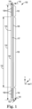
- Figure 1 is a diagram illustrating a fluid ejection die 100 according to one example.
- Die 100 includes a first longitudinal end portion 102 that includes a plurality (e.g., six in the illustrated example) of contact pads 108, a second longitudinal end portion 104 that includes a plurality (e.g., six in the illustrated example) of contact pads 108, and a fluid ejection portion 106 that includes a plurality of fluid actuation devices 107.
- the contact pads 108 in the second longitudinal end portion 104 are longitudinally aligned with the contact pads 108 in the first longitudinal end portion 102, and are positioned at a distance 152 (i.e., along the Y axis) from the contact pads 108 in the first longitudinal end portion 102.
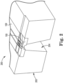
- cavities 312 are filled with mold material 320, such as an epoxy mold compound, plastic, or other suitable moldable material. Filling cavities 312 with mold material 320 forms a carrier 202 around fluid ejection die 100.
- the molding process is a transfer molding process and includes heating the mold material 320 to a liquid form and injecting or vacuum feeding the liquid mold material into cavities 312 (for example, through runners that communicate with cavities 312).
- the feature 306 of the upper mold chase 302 (as positioned along back-side surface 305 of fluid ejection die 100) helps to prevent the mold material from entering the fluid feed holes of die 100 as cavities 312 are filled.
- carrier 202 is molded to include molded back-side surface 330 and molded front-side surface 332, with molded front-side surface 332 substantially coplanar with front-side surface 307 of fluid ejection die 100, and molded back-side surface 330 extending beyond back-side surface 305 of fluid ejection die 100.
- carrier 202 has a thickness that is greater than the thickness of fluid ejection die 100.
- front-side surface 307 of fluid ejection die 100 and a portion of back-side surface 305 of fluid ejection die 100 both remain exposed from carrier 202 (i.e., are not covered by mold material of carrier 202). While one fluid ejection die 100 is illustrated in Figures 3A-3C as being molded into carrier 202, a greater number of fluid ejection dies 100 may be molded into carrier 202.
- the shape of the slot 204 is usually a result of particular slotting process (e.g., laser, anisotropic wet etch, dry etch, or a combination of these), and these processes may have a limited influence on the profile of the slot 204 that can be produced. Examples disclosed herein enable a transfer mold process with slot molding by reducing or eliminating the contact pad EMC flash issue, as described in further detail below.
- particular slotting process e.g., laser, anisotropic wet etch, dry etch, or a combination of these
- these processes may have a limited influence on the profile of the slot 204 that can be produced. Examples disclosed herein enable a transfer mold process with slot molding by reducing or eliminating the contact pad EMC flash issue, as described in further detail below.
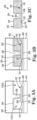
- the fluid ejection die 100 sits on top of the release tape layer 308, which, in one example, is a compliant layer that is about 100um thick.
- the feature 306 of the upper mold chase 302 contacts and applies force to the fluid ejection portion 106 of the fluid ejection die 100, but not the end portions 102 and 104 of the die 100. This force can cause the fluid ejection portion 106 of the die 100 to sink into the release tape layer 308, and cause the end portions 102 and 104 to tilt up toward the upper mold chase 302 during the molding process. This tilting can cause a gap 408 that results in EMC flash in the regions of the contact pads 108.
- the length 404 between the end of the feature 306 and the end 150 of the die 100 is referred to herein as the cantilever length, which plays a role in addressing the contact pad EMC flash issue.
- Examples of the present disclosure use a short cantilever length 404 to reduce or eliminate the contact pad EMC flash issue.
- one or both of the end portions 102 and 104 have a cantilever length 404 that is less than 1.5mm.
- one or both of the end portions 102 and 104 have a cantilever length 404 that is less than 1.3mm.
- one or both of the end portions 102 and 104 have a cantilever length 404 that is less than 1.1mm.
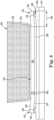
- the slot 204 includes a narrower slot portion 504 longitudinally extending from a wider slot portion 505 near the longitudinal end 502 of the slot 204.
- the narrower slot portion 504 has a uniform width or a substantially uniform width that is less than a uniform width or substantially uniform width of the wider slot portion 505.
- the width of the narrower slot portion 504 is about 25-35% of the width of the wider slot portion 505.
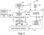
- FIG 8 is a block diagram illustrating a fluid ejection system 800 according to one example.
- Fluid ejection system 800 includes a fluid ejection assembly, such as printhead assembly 802, and a fluid supply assembly, such as ink supply assembly 810.
- printhead assembly 802 may include a fluid ejection device 200 of Figure 2 .
- fluid ejection system 800 also includes a service station assembly 804, a carriage assembly 816, a print media transport assembly 818, and an electronic controller 820. While the following description provides examples of systems and assemblies for fluid handling with regard to ink, the disclosed systems and assemblies are also applicable to the handling of fluids other than ink.
- Printhead assembly 802 includes at least one printhead or fluid ejection die 100 previously described and illustrated with reference to Figure 1 , which ejects drops of ink or fluid through a plurality of orifices or nozzles 107.
- the drops are directed toward a medium, such as print media 824, so as to print onto print media 824.
- print media 824 includes any type of suitable sheet material, such as paper, card stock, transparencies, Mylar, fabric, and the like.
- print media 824 includes media for three-dimensional (3D) printing, such as a powder bed, or media for bioprinting and/or drug discovery testing, such as a reservoir or container.
- nozzles 107 are arranged in at least one column or array such that properly sequenced ejection of ink from nozzles 107 causes characters, symbols, and/or other graphics or images to be printed upon print media 824 as printhead assembly 802 and print media 824 are moved relative to each other.
- Carriage assembly 816 positions printhead assembly 802 relative to print media transport assembly 818, and print media transport assembly 818 positions print media 824 relative to printhead assembly 802.
- a print zone 826 is defined adjacent to nozzles 107 in an area between printhead assembly 802 and print media 824.
- printhead assembly 802 is a scanning type printhead assembly such that carriage assembly 816 moves printhead assembly 802 relative to print media transport assembly 818.
- printhead assembly 802 is a non-scanning type printhead assembly such that carriage assembly 816 fixes printhead assembly 802 at a prescribed position relative to print media transport assembly 818.
- Service station assembly 804 provides for spitting, wiping, capping, and/or priming of printhead assembly 802 to maintain the functionality of printhead assembly 802 and, more specifically, nozzles 107.
- service station assembly 804 may include a rubber blade or wiper which is periodically passed over printhead assembly 802 to wipe and clean nozzles 107 of excess ink.
- service station assembly 804 may include a cap that covers printhead assembly 802 to protect nozzles 107 from drying out during periods of non-use.
- service station assembly 804 may include a spittoon into which printhead assembly 802 ejects ink during spits to ensure that reservoir 812 maintains an appropriate level of pressure and fluidity, and to ensure that nozzles 107 do not clog or weep.
- Functions of service station assembly 804 may include relative motion between service station assembly 804 and printhead assembly 802.
- Electronic controller 820 communicates with printhead assembly 802 through a communication path 803, service station assembly 804 through a communication path 805, carriage assembly 816 through a communication path 817, and print media transport assembly 818 through a communication path 819.
- electronic controller 820 and printhead assembly 802 may communicate via carriage assembly 816 through a communication path 801.
- Electronic controller 820 may also communicate with ink supply assembly 810 such that, in one implementation, a new (or used) ink supply may be detected.
- Electronic controller 820 receives data 828 from a host system, such as a computer, and may include memory for temporarily storing data 828.
- Data 828 may be sent to fluid ejection system 800 along an electronic, infrared, optical or other information transfer path.
- Data 828 represent, for example, a document and/or file to be printed. As such, data 828 form a print job for fluid ejection system 800 and includes at least one print job command and/or command parameter.
- electronic controller 820 provides control of printhead assembly 802 including timing control for ejection of ink drops from nozzles 107.
- electronic controller 820 defines a pattern of ejected ink drops which form characters, symbols, and/or other graphics or images on print media 824. Timing control and, therefore, the pattern of ejected ink drops, is determined by the print job commands and/or command parameters.
- logic and drive circuitry forming a portion of electronic controller 820 is located on printhead assembly 802. In another example, logic and drive circuitry forming a portion of electronic controller 820 is located off printhead assembly 802.
- Examples disclosed herein provide the following features: (1) Enable the use of a slot molding process by reducing or eliminating the contact pad EMC flash issue; (2) use a robust mold process that is less sensitive to slot misalignment; (3) eliminate the silicon slotting process, which reduces the die cost; (4) minimize die cracking by avoiding mechanical/laser damage to the silicon; and (5) superior slot sidewall quality/smoothness to avoid particle shedding issues.
- One example of this disclosure is directed to a fluid ejection device, which includes a fluid ejection die including a first end portion positioned adjacent a first end of the fluid ejection die, and a fluid ejection portion positioned adjacent the first end portion.
- the fluid ejection die includes a contact pad positioned in the first end portion, and a fluid actuation device positioned in the fluid ejection portion.
- a carrier is attached to the fluid ejection die.
- the carrier includes a slot to provide fluid to the fluid actuation device.
- the slot extends longitudinally along the fluid ejection portion to a first slot end. A length from the first slot end to the first end of the fluid ejection die is less than 1.5mm.
- the first end may be a first longitudinal end of the fluid ejection die.
- the length from the first slot end to the first end of the fluid ejection die may be less than 1.3mm.
- the length from the first slot end to the first end of the fluid ejection die may be less than 1.1mm.
- the slot may decrease in width from a first width along the fluid ejection portion to a second, smaller width along an end portion of the slot adjacent the first slot end.
- the fluid ejection die may include a second end portion positioned adjacent a second end of the fluid ejection die.
- the fluid ejection die may include a contact pad positioned in the second end portion.
- the slot may extend longitudinally along the fluid ejection portion to a second slot end.
Landscapes
- Engineering & Computer Science (AREA)
- Manufacturing & Machinery (AREA)
- Coating Apparatus (AREA)
- Moulds For Moulding Plastics Or The Like (AREA)
Claims (14)
- Fluidausstoßvorrichtung (200), umfassend: eine Fluidausstoßdüse (100), die Folgendes einschließtein längliches Halbleitersubstrat (140),einen ersten Längsendabschnitt (102), der neben einem ersten Längsende (148) der Fluidausstoßdüse (100) positioniert ist,und einen Fluidausstoßabschnitt (106), der neben dem ersten Längsendabschnitt (102) positioniert ist, wobei die Fluidausstoßdüse (100) ein Kontaktpad (108) einschließt, das im ersten Längsendabschnitt positioniert ist, und eine Fluidbetätigungsvorrichtung (107), die im Fluidausstoßabschnitt (106) positioniert ist; undeinen Träger (202), der an der Fluidausstoßdüse (100) angebracht ist, wobei der Träger (202) einen Schlitz (204) aufweist, um der Fluidbetätigungsvorrichtung (107) Fluid zuzuführen, wobei sich der Schlitz (204) in Längsrichtung entlang des Fluidausstoßabschnitts (106) zu einem ersten Schlitzende (502) erstreckt, dadurch gekennzeichnet, dass eine Länge (404) vom ersten Schlitzende (502) bis zum ersten Längsende (148) der Fluidausstoßdüse (100) kleiner als 1,5 mm beträgt.
- Fluidausstoßvorrichtung nach Anspruch 1, wobei die Länge vom ersten Schlitzende bis zum ersten Ende der Fluidausstoßdüse weniger als 1,3 mm beträgt.
- Fluidausstoßvorrichtung nach Anspruch 1 oder 2, wobei die Länge vom ersten Schlitzende bis zum ersten Ende der Fluidausstoßdüse weniger als 1,1 mm beträgt.
- Fluidausstoßvorrichtung nach einem der Ansprüche 1 bis 3, wobei die Breite des Schlitzes (204) von einer ersten Breite entlang des Fluidausstoßabschnitts auf eine zweite, kleinere Breite entlang eines Endabschnitts (504, 506) des Schlitzes neben dem ersten Schlitzende abnimmt.
- Fluidausstoßvorrichtung nach einem der Ansprüche 1 bis 4, wobei die Fluidausstoßdüse einen zweiten Endabschnitt (104) einschließt, der neben einem zweiten Ende (150) der Fluidausstoßdüse (100) positioniert ist, wobei die Fluidausstoßdüse ein Kontakpad einschließt, das im zweiten Endabschnitt positioniert ist, wobei sich der Schlitz in Längsrichtung entlang des Fluidausstoßabschnitts zu einem zweiten Schlitzende erstreckt und wobei eine Länge vom zweiten Schlitzende bis zum zweiten Ende der Fluidausstoßdüse weniger als 1,5 mm beträgt.
- Fluidausstoßvorrichtung nach Anspruch 5, wobei das zweite Ende ein zweites Längsende der Fluidausstoßdüse ist.
- Fluidausstoßvorrichtung nach einem der Ansprüche 1 bis 6, wobei der Träger ein starrer Träger ist.
- Fluidausstoßvorrichtung nach einem der Ansprüche 1 bis 7, wobei der Träger ein geformter Träger ist und der Schlitz ein geformter Schlitz ist.
- Fluidausstoßvorrichtung (200) nach Anspruch 1, wobei die Fluidausstoßdüse (100) einen zweiten Endabschnitt (104) einschließt, der neben einem zweiten Ende (150) der Fluidausstoßdüse positioniert ist, und einen Fluidausstoßabschnitt (106), der zwischen dem ersten und dem zweiten Endabschnitt (102, 104) positioniert ist, wobei die Fluidausstoßdüse eine Fluidbetätigungsvorrichtung (107) einschließt, die in dem Fluidausstoßabschnitt positioniert ist; und
umfassend einen starren Träger (202), der an der Fluidausstoßdüse angebracht ist, wobei der starre Träger einen Schlitz (204) aufweist, um einer Rückseite der Fluidausstoßdüse Fluid zuzuführen, wobei sich der Schlitz in Längsrichtung entlang des Fluidausstoßabschnitts zu einem ersten Schlitzende neben dem ersten Endabschnitt erstreckt, und wobei eine Länge vom ersten Schlitzende bis zum ersten Ende der Fluidausstoßdüse weniger als 1,5 mm beträgt. - Fluidausstoßvorrichtung nach Anspruch 9, wobei die Fluidausstoßdüse ein erstes Kontaktpad, das im ersten Endabschnitt positioniert ist, und ein zweites Kontaktpad, das im zweiten Endabschnitt positioniert ist, einschließt.
- Fluidausstoßvorrichtung nach Anspruch 9 oder 10, wobei sich der Schlitz in Längsrichtung entlang des Fluidausstoßabschnitts zu einem zweiten Schlitzende neben dem zweiten Endabschnitt erstreckt, und wobei eine Länge vom zweiten Schlitzende bis zum zweiten Ende der Fluidausstoßdüse weniger als 1,5 mm beträgt.
- Verfahren, umfassend:Anbringen eines Formrahmens (302) an einer Fluidausstoßdüse (100), die ein längliches Halbleitersubstrat (140) und Kontaktpads (108) einschließt, die an einem Längsendabschnitt der Fluidausstoßdüse (100) positioniert sind, wobei der Formrahmen (302) mindestens teilweise mindestens einen Hohlraum definiert, und wobei der Formrahmen ein Schlitzbildungsmerkmal einschließt, das ein erstes Längsende aufweist, das weniger als 1,5 mm von einem ersten Längsende (148) der Fluidausstoßdüse (100) entfernt positioniert ist; undFüllen des mindestens einen Hohlraums mit einer Formmasse, um einen Träger (202) zum Unterstützen der Fluidausstoßdüse (100) zu erzeugen, wobei der Träger einen Schlitz (204) aufweist, der durch das Schlitzbildungsmerkmal definiert ist.
- Verfahren nach Anspruch 12, wobei das Schlitzbildungsmerkmal Fluidzufuhrlöcher (406) der Fluidausstoßdüse abdeckt.
- Verfahren nach Anspruch 12 oder 13, wobei das Schlitzbildungsmerkmal ein zweites Längsende aufweist, das weniger als 1,5 mm von einem zweiten Längsende (150) der Fluidausstoßdüse (100) entfernt positioniert ist.
Applications Claiming Priority (1)
| Application Number | Priority Date | Filing Date | Title |
|---|---|---|---|
| PCT/US2019/016759 WO2020162907A1 (en) | 2019-02-06 | 2019-02-06 | Fluid ejection device with a carrier having a slot |
Publications (2)
| Publication Number | Publication Date |
|---|---|
| EP3921171A1 EP3921171A1 (de) | 2021-12-15 |
| EP3921171B1 true EP3921171B1 (de) | 2025-03-26 |
Family
ID=65529786
Family Applications (1)
| Application Number | Title | Priority Date | Filing Date |
|---|---|---|---|
| EP19707532.8A Active EP3921171B1 (de) | 2019-02-06 | 2019-02-06 | Flüssigkeitsausstossvorrichtung mit einem träger mit einem schlitz |
Country Status (4)
| Country | Link |
|---|---|
| US (1) | US11390081B2 (de) |
| EP (1) | EP3921171B1 (de) |
| CN (1) | CN113365842B (de) |
| WO (1) | WO2020162907A1 (de) |
Family Cites Families (15)
| Publication number | Priority date | Publication date | Assignee | Title |
|---|---|---|---|---|
| EP1024003B1 (de) * | 1999-01-29 | 2002-10-16 | Seiko Epson Corporation | Tintenstrahldruckkopf mit verbesserten Tintenzufuhrkanälen |
| US7122884B2 (en) | 2002-04-16 | 2006-10-17 | Fairchild Semiconductor Corporation | Robust leaded molded packages and methods for forming the same |
| US7025439B2 (en) * | 2004-03-15 | 2006-04-11 | Lexmark International, Inc. | Ink jet printer with extended nozzle plate and method |
| US7275815B2 (en) * | 2004-12-01 | 2007-10-02 | Lexmark International, Inc. | Die attach methods and apparatus for micro-fluid ejection device |
| US7572675B2 (en) | 2006-01-24 | 2009-08-11 | Asm Technology Singapore Pte Ltd. | Mold flash removal process for electronic devices |
| JP4681654B2 (ja) | 2006-03-03 | 2011-05-11 | シルバーブルック リサーチ ピーティワイ リミテッド | インクジェットプリンタ |
| TW200926380A (en) | 2007-12-10 | 2009-06-16 | Powertech Technology Inc | Semiconductor package and substrate for the same |
| US8251497B2 (en) | 2008-12-18 | 2012-08-28 | Eastman Kodak Company | Injection molded mounting substrate |
| CN102470671B (zh) * | 2009-07-27 | 2014-11-26 | 扎姆泰科有限公司 | 具有后侧电连接的喷墨打印头组件 |
| BR112014007224B1 (pt) | 2011-09-28 | 2020-06-16 | Hewlett-Packard Development Company, L.P. | Dispositivo de ejeção de fluido e método de circulação de fluido |
| US20150145925A1 (en) | 2012-05-31 | 2015-05-28 | Rio Rivas | Printheads with conductor traces across slots |
| US9446587B2 (en) * | 2013-02-28 | 2016-09-20 | Hewlett-Packard Development Company, L.P. | Molded printhead |
| BR112015020860B1 (pt) * | 2013-02-28 | 2021-04-13 | Hewlett-Packard Development Company, L.P. | Estrutura e sistema de fluxo de fluido com um microdispositivo dispensador de fluido e uma moldagem monolítica |
| MX372916B (es) * | 2013-11-27 | 2020-04-27 | Hewlett Packard Development Co | Aparato de eyeccion de fluido con conector de suministro de energia individual. |
| US9873250B2 (en) * | 2016-03-14 | 2018-01-23 | Stmicroelectronics, Inc. | Microfluidic assembly with mechanical bonds |
-
2019
- 2019-02-06 EP EP19707532.8A patent/EP3921171B1/de active Active
- 2019-02-06 CN CN201980090325.4A patent/CN113365842B/zh active Active
- 2019-02-06 WO PCT/US2019/016759 patent/WO2020162907A1/en not_active Ceased
- 2019-02-06 US US16/769,907 patent/US11390081B2/en active Active
Also Published As
| Publication number | Publication date |
|---|---|
| WO2020162907A1 (en) | 2020-08-13 |
| CN113365842B (zh) | 2022-10-14 |
| CN113365842A (zh) | 2021-09-07 |
| US20210229438A1 (en) | 2021-07-29 |
| US11390081B2 (en) | 2022-07-19 |
| EP3921171A1 (de) | 2021-12-15 |
Similar Documents
| Publication | Publication Date | Title |
|---|---|---|
| US10946648B2 (en) | Fluid ejection die fluid recirculation | |
| EP3921171B1 (de) | Flüssigkeitsausstossvorrichtung mit einem träger mit einem schlitz | |
| US11827021B2 (en) | Applying mold chase structure to end portion of fluid ejection die | |
| TWI743355B (zh) | 模製進入模製體的流體噴射晶粒以及形成流體噴射裝置的方法 | |
| TWI743382B (zh) | 流體噴出裝置及形成流體噴出裝置之方法 | |
| EP3717259B1 (de) | Fluidausstossvorrichtungen mit kontaktpads | |
| CN100453321C (zh) | 点滴喷射组件 | |
| US8172360B2 (en) | Printhead servicing system and method | |
| JP2009190188A (ja) | インクジェットヘッド及びインクジェット記録装置 | |
| JP2018199278A (ja) | 液体吐出ヘッドおよび液体吐出装置 | |
| JP2024049554A (ja) | 液体吐出ヘッドおよび記録装置 | |
| HK40012778A (en) | Fluid ejection die molded into molded body | |
| HK40012778B (en) | Fluid ejection die molded into molded body | |
| JP2018199279A (ja) | 液体吐出ヘッドおよび液体吐出装置 |
Legal Events
| Date | Code | Title | Description |
|---|---|---|---|
| STAA | Information on the status of an ep patent application or granted ep patent |
Free format text: STATUS: UNKNOWN |
|
| STAA | Information on the status of an ep patent application or granted ep patent |
Free format text: STATUS: THE INTERNATIONAL PUBLICATION HAS BEEN MADE |
|
| PUAI | Public reference made under article 153(3) epc to a published international application that has entered the european phase |
Free format text: ORIGINAL CODE: 0009012 |
|
| STAA | Information on the status of an ep patent application or granted ep patent |
Free format text: STATUS: REQUEST FOR EXAMINATION WAS MADE |
|
| 17P | Request for examination filed |
Effective date: 20210616 |
|
| AK | Designated contracting states |
Kind code of ref document: A1 Designated state(s): AL AT BE BG CH CY CZ DE DK EE ES FI FR GB GR HR HU IE IS IT LI LT LU LV MC MK MT NL NO PL PT RO RS SE SI SK SM TR |
|
| DAV | Request for validation of the european patent (deleted) | ||
| DAX | Request for extension of the european patent (deleted) | ||
| STAA | Information on the status of an ep patent application or granted ep patent |
Free format text: STATUS: EXAMINATION IS IN PROGRESS |
|
| 17Q | First examination report despatched |
Effective date: 20231009 |
|
| GRAP | Despatch of communication of intention to grant a patent |
Free format text: ORIGINAL CODE: EPIDOSNIGR1 |
|
| STAA | Information on the status of an ep patent application or granted ep patent |
Free format text: STATUS: GRANT OF PATENT IS INTENDED |
|
| INTG | Intention to grant announced |
Effective date: 20240905 |
|
| GRAS | Grant fee paid |
Free format text: ORIGINAL CODE: EPIDOSNIGR3 |
|
| GRAA | (expected) grant |
Free format text: ORIGINAL CODE: 0009210 |
|
| STAA | Information on the status of an ep patent application or granted ep patent |
Free format text: STATUS: THE PATENT HAS BEEN GRANTED |
|
| AK | Designated contracting states |
Kind code of ref document: B1 Designated state(s): AL AT BE BG CH CY CZ DE DK EE ES FI FR GB GR HR HU IE IS IT LI LT LU LV MC MK MT NL NO PL PT RO RS SE SI SK SM TR |
|
| REG | Reference to a national code |
Ref country code: GB Ref legal event code: FG4D |
|
| REG | Reference to a national code |
Ref country code: CH Ref legal event code: EP |
|
| REG | Reference to a national code |
Ref country code: DE Ref legal event code: R096 Ref document number: 602019067734 Country of ref document: DE |
|
| REG | Reference to a national code |
Ref country code: IE Ref legal event code: FG4D |
|
| PG25 | Lapsed in a contracting state [announced via postgrant information from national office to epo] |
Ref country code: RS Free format text: LAPSE BECAUSE OF FAILURE TO SUBMIT A TRANSLATION OF THE DESCRIPTION OR TO PAY THE FEE WITHIN THE PRESCRIBED TIME-LIMIT Effective date: 20250626 |
|
| PG25 | Lapsed in a contracting state [announced via postgrant information from national office to epo] |
Ref country code: FI Free format text: LAPSE BECAUSE OF FAILURE TO SUBMIT A TRANSLATION OF THE DESCRIPTION OR TO PAY THE FEE WITHIN THE PRESCRIBED TIME-LIMIT Effective date: 20250326 |
|
| REG | Reference to a national code |
Ref country code: LT Ref legal event code: MG9D |
|
| PG25 | Lapsed in a contracting state [announced via postgrant information from national office to epo] |
Ref country code: NO Free format text: LAPSE BECAUSE OF FAILURE TO SUBMIT A TRANSLATION OF THE DESCRIPTION OR TO PAY THE FEE WITHIN THE PRESCRIBED TIME-LIMIT Effective date: 20250626 |
|
| PG25 | Lapsed in a contracting state [announced via postgrant information from national office to epo] |
Ref country code: HR Free format text: LAPSE BECAUSE OF FAILURE TO SUBMIT A TRANSLATION OF THE DESCRIPTION OR TO PAY THE FEE WITHIN THE PRESCRIBED TIME-LIMIT Effective date: 20250326 |
|
| PG25 | Lapsed in a contracting state [announced via postgrant information from national office to epo] |
Ref country code: LV Free format text: LAPSE BECAUSE OF FAILURE TO SUBMIT A TRANSLATION OF THE DESCRIPTION OR TO PAY THE FEE WITHIN THE PRESCRIBED TIME-LIMIT Effective date: 20250326 |
|
| PG25 | Lapsed in a contracting state [announced via postgrant information from national office to epo] |
Ref country code: GR Free format text: LAPSE BECAUSE OF FAILURE TO SUBMIT A TRANSLATION OF THE DESCRIPTION OR TO PAY THE FEE WITHIN THE PRESCRIBED TIME-LIMIT Effective date: 20250627 Ref country code: BG Free format text: LAPSE BECAUSE OF FAILURE TO SUBMIT A TRANSLATION OF THE DESCRIPTION OR TO PAY THE FEE WITHIN THE PRESCRIBED TIME-LIMIT Effective date: 20250326 |
|
| REG | Reference to a national code |
Ref country code: NL Ref legal event code: MP Effective date: 20250326 |
|
| PG25 | Lapsed in a contracting state [announced via postgrant information from national office to epo] |
Ref country code: NL Free format text: LAPSE BECAUSE OF FAILURE TO SUBMIT A TRANSLATION OF THE DESCRIPTION OR TO PAY THE FEE WITHIN THE PRESCRIBED TIME-LIMIT Effective date: 20250326 |
|
| PG25 | Lapsed in a contracting state [announced via postgrant information from national office to epo] |
Ref country code: SE Free format text: LAPSE BECAUSE OF FAILURE TO SUBMIT A TRANSLATION OF THE DESCRIPTION OR TO PAY THE FEE WITHIN THE PRESCRIBED TIME-LIMIT Effective date: 20250326 |
|
| REG | Reference to a national code |
Ref country code: AT Ref legal event code: MK05 Ref document number: 1778689 Country of ref document: AT Kind code of ref document: T Effective date: 20250326 |
|
| PG25 | Lapsed in a contracting state [announced via postgrant information from national office to epo] |
Ref country code: SM Free format text: LAPSE BECAUSE OF FAILURE TO SUBMIT A TRANSLATION OF THE DESCRIPTION OR TO PAY THE FEE WITHIN THE PRESCRIBED TIME-LIMIT Effective date: 20250326 |
|
| PG25 | Lapsed in a contracting state [announced via postgrant information from national office to epo] |
Ref country code: ES Free format text: LAPSE BECAUSE OF FAILURE TO SUBMIT A TRANSLATION OF THE DESCRIPTION OR TO PAY THE FEE WITHIN THE PRESCRIBED TIME-LIMIT Effective date: 20250326 Ref country code: PT Free format text: LAPSE BECAUSE OF FAILURE TO SUBMIT A TRANSLATION OF THE DESCRIPTION OR TO PAY THE FEE WITHIN THE PRESCRIBED TIME-LIMIT Effective date: 20250728 |
|
| PG25 | Lapsed in a contracting state [announced via postgrant information from national office to epo] |
Ref country code: IT Free format text: LAPSE BECAUSE OF FAILURE TO SUBMIT A TRANSLATION OF THE DESCRIPTION OR TO PAY THE FEE WITHIN THE PRESCRIBED TIME-LIMIT Effective date: 20250326 Ref country code: PL Free format text: LAPSE BECAUSE OF FAILURE TO SUBMIT A TRANSLATION OF THE DESCRIPTION OR TO PAY THE FEE WITHIN THE PRESCRIBED TIME-LIMIT Effective date: 20250326 |
|
| PG25 | Lapsed in a contracting state [announced via postgrant information from national office to epo] |
Ref country code: AT Free format text: LAPSE BECAUSE OF FAILURE TO SUBMIT A TRANSLATION OF THE DESCRIPTION OR TO PAY THE FEE WITHIN THE PRESCRIBED TIME-LIMIT Effective date: 20250326 |
|
| PG25 | Lapsed in a contracting state [announced via postgrant information from national office to epo] |
Ref country code: EE Free format text: LAPSE BECAUSE OF FAILURE TO SUBMIT A TRANSLATION OF THE DESCRIPTION OR TO PAY THE FEE WITHIN THE PRESCRIBED TIME-LIMIT Effective date: 20250326 |
|
| PG25 | Lapsed in a contracting state [announced via postgrant information from national office to epo] |
Ref country code: RO Free format text: LAPSE BECAUSE OF FAILURE TO SUBMIT A TRANSLATION OF THE DESCRIPTION OR TO PAY THE FEE WITHIN THE PRESCRIBED TIME-LIMIT Effective date: 20250326 |
|
| PG25 | Lapsed in a contracting state [announced via postgrant information from national office to epo] |
Ref country code: SK Free format text: LAPSE BECAUSE OF FAILURE TO SUBMIT A TRANSLATION OF THE DESCRIPTION OR TO PAY THE FEE WITHIN THE PRESCRIBED TIME-LIMIT Effective date: 20250326 |
|
| PG25 | Lapsed in a contracting state [announced via postgrant information from national office to epo] |
Ref country code: IS Free format text: LAPSE BECAUSE OF FAILURE TO SUBMIT A TRANSLATION OF THE DESCRIPTION OR TO PAY THE FEE WITHIN THE PRESCRIBED TIME-LIMIT Effective date: 20250726 |
|
| PG25 | Lapsed in a contracting state [announced via postgrant information from national office to epo] |
Ref country code: DK Free format text: LAPSE BECAUSE OF FAILURE TO SUBMIT A TRANSLATION OF THE DESCRIPTION OR TO PAY THE FEE WITHIN THE PRESCRIBED TIME-LIMIT Effective date: 20250326 |