EP3920371A1 - Power supply method and power management device - Google Patents
Power supply method and power management device Download PDFInfo
- Publication number
- EP3920371A1 EP3920371A1 EP20747913.0A EP20747913A EP3920371A1 EP 3920371 A1 EP3920371 A1 EP 3920371A1 EP 20747913 A EP20747913 A EP 20747913A EP 3920371 A1 EP3920371 A1 EP 3920371A1
- Authority
- EP
- European Patent Office
- Prior art keywords
- management system
- energy management
- response
- consumer
- facility
- Prior art date
- Legal status (The legal status is an assumption and is not a legal conclusion. Google has not performed a legal analysis and makes no representation as to the accuracy of the status listed.)
- Withdrawn
Links
Images




Classifications
-
- H—ELECTRICITY
- H02—GENERATION; CONVERSION OR DISTRIBUTION OF ELECTRIC POWER
- H02J—ELECTRIC POWER NETWORKS; CIRCUIT ARRANGEMENTS OR SYSTEMS FOR SUPPLYING OR DISTRIBUTING ELECTRIC POWER; SYSTEMS FOR STORING ELECTRIC ENERGY
- H02J13/00—Circuit arrangements for providing remote monitoring or remote control of equipment in a power distribution network
- H02J13/13—Circuit arrangements for providing remote monitoring or remote control of equipment in a power distribution network characterised by the transmission of data to equipment in the power network
- H02J13/1311—Circuit arrangements for providing remote monitoring or remote control of equipment in a power distribution network characterised by the transmission of data to equipment in the power network using the power network as support for the transmission
-
- H—ELECTRICITY
- H02—GENERATION; CONVERSION OR DISTRIBUTION OF ELECTRIC POWER
- H02J—ELECTRIC POWER NETWORKS; CIRCUIT ARRANGEMENTS OR SYSTEMS FOR SUPPLYING OR DISTRIBUTING ELECTRIC POWER; SYSTEMS FOR STORING ELECTRIC ENERGY
- H02J3/00—Circuit arrangements for AC mains or AC distribution networks
- H02J3/38—Arrangements for feeding a single network from two or more generators or sources in parallel; Arrangements for feeding already energised networks from additional generators or sources in parallel
- H02J3/381—Dispersed generators
-
- H—ELECTRICITY
- H02—GENERATION; CONVERSION OR DISTRIBUTION OF ELECTRIC POWER
- H02J—ELECTRIC POWER NETWORKS; CIRCUIT ARRANGEMENTS OR SYSTEMS FOR SUPPLYING OR DISTRIBUTING ELECTRIC POWER; SYSTEMS FOR STORING ELECTRIC ENERGY
- H02J13/00—Circuit arrangements for providing remote monitoring or remote control of equipment in a power distribution network
- H02J13/18—Circuit arrangements for providing remote monitoring or remote control of equipment in a power distribution network characterised by the remotely-controlled equipment, e.g. converters or transformers
- H02J13/333—Circuit arrangements for providing remote monitoring or remote control of equipment in a power distribution network characterised by the remotely-controlled equipment, e.g. converters or transformers the equipment forming part of substations
-
- H—ELECTRICITY
- H02—GENERATION; CONVERSION OR DISTRIBUTION OF ELECTRIC POWER
- H02J—ELECTRIC POWER NETWORKS; CIRCUIT ARRANGEMENTS OR SYSTEMS FOR SUPPLYING OR DISTRIBUTING ELECTRIC POWER; SYSTEMS FOR STORING ELECTRIC ENERGY
- H02J3/00—Circuit arrangements for AC mains or AC distribution networks
- H02J3/17—Demand-responsive operation of AC power transmission or distribution networks
-
- H—ELECTRICITY
- H02—GENERATION; CONVERSION OR DISTRIBUTION OF ELECTRIC POWER
- H02J—ELECTRIC POWER NETWORKS; CIRCUIT ARRANGEMENTS OR SYSTEMS FOR SUPPLYING OR DISTRIBUTING ELECTRIC POWER; SYSTEMS FOR STORING ELECTRIC ENERGY
- H02J3/00—Circuit arrangements for AC mains or AC distribution networks
- H02J3/38—Arrangements for feeding a single network from two or more generators or sources in parallel; Arrangements for feeding already energised networks from additional generators or sources in parallel
- H02J3/46—Controlling the sharing of generated power between the generators, sources or networks
-
- H—ELECTRICITY
- H02—GENERATION; CONVERSION OR DISTRIBUTION OF ELECTRIC POWER
- H02J—ELECTRIC POWER NETWORKS; CIRCUIT ARRANGEMENTS OR SYSTEMS FOR SUPPLYING OR DISTRIBUTING ELECTRIC POWER; SYSTEMS FOR STORING ELECTRIC ENERGY
- H02J2101/00—Supply or distribution of decentralised, dispersed or local electric power generation
- H02J2101/20—Dispersed power generation using renewable energy sources
- H02J2101/22—Solar energy
-
- H—ELECTRICITY
- H02—GENERATION; CONVERSION OR DISTRIBUTION OF ELECTRIC POWER
- H02J—ELECTRIC POWER NETWORKS; CIRCUIT ARRANGEMENTS OR SYSTEMS FOR SUPPLYING OR DISTRIBUTING ELECTRIC POWER; SYSTEMS FOR STORING ELECTRIC ENERGY
- H02J2101/00—Supply or distribution of decentralised, dispersed or local electric power generation
- H02J2101/20—Dispersed power generation using renewable energy sources
- H02J2101/28—Wind energy
-
- H—ELECTRICITY
- H02—GENERATION; CONVERSION OR DISTRIBUTION OF ELECTRIC POWER
- H02J—ELECTRIC POWER NETWORKS; CIRCUIT ARRANGEMENTS OR SYSTEMS FOR SUPPLYING OR DISTRIBUTING ELECTRIC POWER; SYSTEMS FOR STORING ELECTRIC ENERGY
- H02J2101/00—Supply or distribution of decentralised, dispersed or local electric power generation
- H02J2101/20—Dispersed power generation using renewable energy sources
- H02J2101/30—Fuel cells
-
- H—ELECTRICITY
- H02—GENERATION; CONVERSION OR DISTRIBUTION OF ELECTRIC POWER
- H02J—ELECTRIC POWER NETWORKS; CIRCUIT ARRANGEMENTS OR SYSTEMS FOR SUPPLYING OR DISTRIBUTING ELECTRIC POWER; SYSTEMS FOR STORING ELECTRIC ENERGY
- H02J3/00—Circuit arrangements for AC mains or AC distribution networks
- H02J3/28—Arrangements for balancing of the load in networks by storage of energy
- H02J3/32—Arrangements for balancing of the load in networks by storage of energy using batteries or super capacitors with converting means
-
- Y—GENERAL TAGGING OF NEW TECHNOLOGICAL DEVELOPMENTS; GENERAL TAGGING OF CROSS-SECTIONAL TECHNOLOGIES SPANNING OVER SEVERAL SECTIONS OF THE IPC; TECHNICAL SUBJECTS COVERED BY FORMER USPC CROSS-REFERENCE ART COLLECTIONS [XRACs] AND DIGESTS
- Y02—TECHNOLOGIES OR APPLICATIONS FOR MITIGATION OR ADAPTATION AGAINST CLIMATE CHANGE
- Y02B—CLIMATE CHANGE MITIGATION TECHNOLOGIES RELATED TO BUILDINGS, e.g. HOUSING, HOUSE APPLIANCES OR RELATED END-USER APPLICATIONS
- Y02B70/00—Technologies for an efficient end-user side electric power management and consumption
- Y02B70/30—Systems integrating technologies related to power network operation and communication or information technologies for improving the carbon footprint of the management of residential or tertiary loads, i.e. smart grids as climate change mitigation technology in the buildings sector, including also the last stages of power distribution and the control, monitoring or operating management systems at local level
- Y02B70/3225—Demand response systems, e.g. load shedding, peak shaving
-
- Y—GENERAL TAGGING OF NEW TECHNOLOGICAL DEVELOPMENTS; GENERAL TAGGING OF CROSS-SECTIONAL TECHNOLOGIES SPANNING OVER SEVERAL SECTIONS OF THE IPC; TECHNICAL SUBJECTS COVERED BY FORMER USPC CROSS-REFERENCE ART COLLECTIONS [XRACs] AND DIGESTS
- Y02—TECHNOLOGIES OR APPLICATIONS FOR MITIGATION OR ADAPTATION AGAINST CLIMATE CHANGE
- Y02E—REDUCTION OF GREENHOUSE GAS [GHG] EMISSIONS, RELATED TO ENERGY GENERATION, TRANSMISSION OR DISTRIBUTION
- Y02E40/00—Technologies for an efficient electrical power generation, transmission or distribution
- Y02E40/70—Smart grids as climate change mitigation technology in the energy generation sector
-
- Y—GENERAL TAGGING OF NEW TECHNOLOGICAL DEVELOPMENTS; GENERAL TAGGING OF CROSS-SECTIONAL TECHNOLOGIES SPANNING OVER SEVERAL SECTIONS OF THE IPC; TECHNICAL SUBJECTS COVERED BY FORMER USPC CROSS-REFERENCE ART COLLECTIONS [XRACs] AND DIGESTS
- Y02—TECHNOLOGIES OR APPLICATIONS FOR MITIGATION OR ADAPTATION AGAINST CLIMATE CHANGE
- Y02E—REDUCTION OF GREENHOUSE GAS [GHG] EMISSIONS, RELATED TO ENERGY GENERATION, TRANSMISSION OR DISTRIBUTION
- Y02E60/00—Enabling technologies; Technologies with a potential or indirect contribution to GHG emissions mitigation
-
- Y—GENERAL TAGGING OF NEW TECHNOLOGICAL DEVELOPMENTS; GENERAL TAGGING OF CROSS-SECTIONAL TECHNOLOGIES SPANNING OVER SEVERAL SECTIONS OF THE IPC; TECHNICAL SUBJECTS COVERED BY FORMER USPC CROSS-REFERENCE ART COLLECTIONS [XRACs] AND DIGESTS
- Y04—INFORMATION OR COMMUNICATION TECHNOLOGIES HAVING AN IMPACT ON OTHER TECHNOLOGY AREAS
- Y04S—SYSTEMS INTEGRATING TECHNOLOGIES RELATED TO POWER NETWORK OPERATION, COMMUNICATION OR INFORMATION TECHNOLOGIES FOR IMPROVING THE ELECTRICAL POWER GENERATION, TRANSMISSION, DISTRIBUTION, MANAGEMENT OR USAGE, i.e. SMART GRIDS
- Y04S10/00—Systems supporting electrical power generation, transmission or distribution
- Y04S10/12—Monitoring or controlling equipment for energy generation units, e.g. distributed energy generation [DER] or load-side generation
- Y04S10/123—Monitoring or controlling equipment for energy generation units, e.g. distributed energy generation [DER] or load-side generation the energy generation units being or involving renewable energy sources
-
- Y—GENERAL TAGGING OF NEW TECHNOLOGICAL DEVELOPMENTS; GENERAL TAGGING OF CROSS-SECTIONAL TECHNOLOGIES SPANNING OVER SEVERAL SECTIONS OF THE IPC; TECHNICAL SUBJECTS COVERED BY FORMER USPC CROSS-REFERENCE ART COLLECTIONS [XRACs] AND DIGESTS
- Y04—INFORMATION OR COMMUNICATION TECHNOLOGIES HAVING AN IMPACT ON OTHER TECHNOLOGY AREAS
- Y04S—SYSTEMS INTEGRATING TECHNOLOGIES RELATED TO POWER NETWORK OPERATION, COMMUNICATION OR INFORMATION TECHNOLOGIES FOR IMPROVING THE ELECTRICAL POWER GENERATION, TRANSMISSION, DISTRIBUTION, MANAGEMENT OR USAGE, i.e. SMART GRIDS
- Y04S10/00—Systems supporting electrical power generation, transmission or distribution
- Y04S10/14—Energy storage units
-
- Y—GENERAL TAGGING OF NEW TECHNOLOGICAL DEVELOPMENTS; GENERAL TAGGING OF CROSS-SECTIONAL TECHNOLOGIES SPANNING OVER SEVERAL SECTIONS OF THE IPC; TECHNICAL SUBJECTS COVERED BY FORMER USPC CROSS-REFERENCE ART COLLECTIONS [XRACs] AND DIGESTS
- Y04—INFORMATION OR COMMUNICATION TECHNOLOGIES HAVING AN IMPACT ON OTHER TECHNOLOGY AREAS
- Y04S—SYSTEMS INTEGRATING TECHNOLOGIES RELATED TO POWER NETWORK OPERATION, COMMUNICATION OR INFORMATION TECHNOLOGIES FOR IMPROVING THE ELECTRICAL POWER GENERATION, TRANSMISSION, DISTRIBUTION, MANAGEMENT OR USAGE, i.e. SMART GRIDS
- Y04S20/00—Management or operation of end-user stationary applications or the last stages of power distribution; Controlling, monitoring or operating thereof
- Y04S20/20—End-user application control systems
- Y04S20/222—Demand response systems, e.g. load shedding, peak shaving
-
- Y—GENERAL TAGGING OF NEW TECHNOLOGICAL DEVELOPMENTS; GENERAL TAGGING OF CROSS-SECTIONAL TECHNOLOGIES SPANNING OVER SEVERAL SECTIONS OF THE IPC; TECHNICAL SUBJECTS COVERED BY FORMER USPC CROSS-REFERENCE ART COLLECTIONS [XRACs] AND DIGESTS
- Y04—INFORMATION OR COMMUNICATION TECHNOLOGIES HAVING AN IMPACT ON OTHER TECHNOLOGY AREAS
- Y04S—SYSTEMS INTEGRATING TECHNOLOGIES RELATED TO POWER NETWORK OPERATION, COMMUNICATION OR INFORMATION TECHNOLOGIES FOR IMPROVING THE ELECTRICAL POWER GENERATION, TRANSMISSION, DISTRIBUTION, MANAGEMENT OR USAGE, i.e. SMART GRIDS
- Y04S40/00—Systems for electrical power generation, transmission, distribution or end-user application management characterised by the use of communication or information technologies, or communication or information technology specific aspects supporting them
- Y04S40/12—Systems for electrical power generation, transmission, distribution or end-user application management characterised by the use of communication or information technologies, or communication or information technology specific aspects supporting them characterised by data transport means between the monitoring, controlling or managing units and monitored, controlled or operated electrical equipment
- Y04S40/121—Systems for electrical power generation, transmission, distribution or end-user application management characterised by the use of communication or information technologies, or communication or information technology specific aspects supporting them characterised by data transport means between the monitoring, controlling or managing units and monitored, controlled or operated electrical equipment using the power network as support for the transmission
Definitions
- the present disclosure relates to a power supply method and an energy management system.
- VPP virtual power plants
- DR demand response
- the VPP in such a demonstration is realized by combining power storage apparatuses and energy management systems (EMSs) of each facility, and configured as a system to perform communication between each of the energy management systems and a server apparatus, using the Internet environment.
- EMSs energy management systems
- Patent Document 1 Japanese application publication No. 2017-011968
- a first aspect of the present disclosure is a power supply method in which a first energy management system provided at a first consumer's facility transmits a search request, and a second energy management system provided at a second consumer's facility transmits, to the first energy management system, in response to the search request, a search response including information relating to reliability of the second consumer's facility. Furthermore, the first energy management system transmits, to the second energy management system selected in accordance with the search response including the information relating to the reliability of the second consumer's facility, a demand response request for requesting, using a demand response, a supply of electric energy having a designated value.
- a second aspect of the present disclosure is an energy management system that functions as a first energy management system in a power supply system including the first energy management system provided at a first consumer's facility and a second energy management system provided at a second consumer's facility.
- the energy management system includes a searcher, a demand response processor, and a report acquirer.
- the searcher is configured to transmit a search request for searching for a consumer's facility capable of supplying electric energy to the first consumer's facility.
- the searcher is configured to receive, from the second energy management system, a search response including information relating to reliability of the second consumer's facility in response to the second energy management system receiving the search request.
- the demand response processor is configured to transmit, to the second energy management system selected in accordance with the information relating to the reliability of the second consumer's facility, a demand response request for requesting, using a demand response, a supply of electric energy having a designated value.
- a third aspect of the present disclosure is an energy management system that functions as a second energy management system in a power supply system including a first energy management system provided at a first consumer's facility and the second energy management system provided at a second consumer's facility.
- the energy management system includes a responder, a demand response processor, and a report transmitter.
- the responder is configured to transmit, to the first energy management system, a search response including information relating to reliability of the second consumer's facility in response to a search request received from the first energy management system.
- the demand response processor is configured to receive, from the first energy management system, a demand response request for requesting, using a demand response, a supply of electric energy having a designated value.
- FIG. 1 and FIG. 2 An example of a sequence in such a VPP is illustrated in FIG. 1 and FIG. 2 .
- the present disclosure has been made in light of the above-described problems, and when a desired electric energy is supplied from a response-side consumer to a demand-side consumer, the present disclosure can reduce an increase in a communication volume and an increase in a processing volume in an EMS of the demand-side consumer due to reports transmitted from an EMS of the response-side consumer to the EMS of the demand-side consumer.
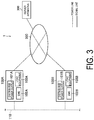
- FIG. 3 is a diagram illustrating an example of a configuration of a power supply system 1 according to the present embodiment.
- the power supply system 1 includes a plurality of facilities 100A/100B and a server apparatus 300.
- Each of the facilities 100A/100B and the server apparatus 300 are connected to a network 200.
- the network 200 may include the Internet, or may include a dedicated line such as a virtual private network (VPN).
- VPN virtual private network
- the facilities 100A/100B are exemplified as a plurality of facilities 100.
- Each of the facilities 100 corresponds to one consumer's facility (hereinafter simply referred to as a "consumer").
- Each of the facilities 100A/100B is connected to a power grid 110.
- a flow of power from the power grid 110 to the facility 100 is referred to as a "power flow,” and the flow of power from the facility 100 to the power grid 110 is referred to as a "reverse power flow.”
- the power grid 110 may be a power transmission network that is separated from power companies and provided externally to the consumers, in which the power is interchanged among the consumers in an area.
- the facility 100A includes a distributed power supply 101A, an EMS 102A, and load equipment 103A
- the facility 100B includes a distributed power supply 101B, an EMS 102B, and load equipment 103B.
- the distributed power supply 101A/101B may be a fuel cell apparatus that generates power using fuel.
- the fuel cell apparatus is an apparatus that generates power using fuel.
- the fuel cell apparatus may be a solid oxide fuel cell (SOFC), a polymer electrolyte fuel cell (PEFC), a phosphoric acid fuel cell (PAFC), and/or a molten carbonate fuel cell (MCFC).
- SOFC solid oxide fuel cell
- PEFC polymer electrolyte fuel cell
- PAFC phosphoric acid fuel cell
- MCFC molten carbonate fuel cell
- a distributed power supply 101 may be a power generation apparatus that generates power using natural energy such as sunlight, wind power, water power, or geothermal heat.
- the distributed power supply 101A/101B may be a power storage apparatus that performs power charging and power discharge.
- the power storage apparatus is an apparatus that performs power charging and power discharge under the control of the EMS 102A/102B.
- the power storage apparatus is a lithium ion power storage apparatus, a lead power storage apparatus, a nickel hydrogen power storage apparatus, or the like.
- the power discharged by the power storage apparatus may be supplied to the load equipment 103A/103B in the facility 100A/100B, or may be supplied to the power grid 110.
- a "boost mode" may be implemented in which power generated by a power generation apparatus is sold, and the load equipment 103A/103B in the facility 100A/100B is operated by the power discharged by the power storage apparatus.
- the power storage apparatus can perform charging using power supplied by the power grid 110, or excess power generated by the power generation apparatus, for example.
- the EMS 102A/102B is an energy management system that manages the power of the facility 100A/100B.
- the EMS 102A/102B may control operating states of the distributed power supply 101A/101B and load equipment 103. Specifically, the EMS 102A/102B may control the power charging or the power discharge of the power storage apparatus.
- the EMS 102A/102B is an example of a virtual end node (VEN).
- the load equipment 103A/103B is equipment that consumes power.
- the load equipment 103A/103B is air conditioning equipment, illumination equipment, audio visual (AV) equipment, or the like.
- the server apparatus 300 is a server apparatus managed by a power company, such as a power generation operator, a power transmission and distribution operator, a retailer, or a resource aggregator.
- the resource aggregator is a power company that supplies power of the reverse power flow to the power generation operator, the power transmission and distribution operator, the retailer, or the like, in a VPP.
- the server apparatus 300 is an example of an entity that buys the power of the reverse power flow.
- the server apparatus 300 is configured to manage the facilities 100A/100B.
- an example of a configuration of an EMS that functions as the EMS 102A (a first energy management system) in the power supply system 1 will be described below with reference to FIG. 4 .
- an example of a configuration of an EMS that functions as the EMS 102B (a second energy management system) in the power supply system 1 will be described.
- the EMS according to the present embodiment may have both the configuration of the EMS 102A and the configuration of the EMS 102B.
- the EMS 102A includes a communicator 111, a database 112, a searcher 113, a DR processor 114, a report acquirer 115, and a notifier 116.
- some or all of the searcher 113, the DR processor 114, the report acquirer 115, and the notifier 116 may be included in a controller (not illustrated) of the EMS 102A.
- the communicator 111 is configured by a communication module, and communicates with the distributed power supply 101A and the load equipment 103A of the facility 100A, and with the server apparatus 300.
- the communicator 111 communicates with the server apparatus 300 in accordance with a first communication protocol.
- a communication protocol compliant with OpenADR 2.0, or a proprietary dedicated communication protocol can be used.
- the communicator 111 communicates with the distributed power supply 101A and the load equipment 103A in accordance with a second communication protocol.
- a communication protocol compliant with ECHONET Lite, Smart Energy Profile (SEP) 2.0, KNX, or a proprietary dedicated communication protocol can be used.
- the database 112 is configured by a storage medium such as a nonvolatile memory and/or an HDD, and stores data relating to the facility 100A.
- the searcher 113 is configured to transmit a search request to the network 200 via the communicator 111.
- the search request is a signal for searching for other consumers who can supply electric energy to the EMS 102A.
- Such a search request includes information indicating electric energy required at the facility 100A.
- Such a search request may be, for example, a signal prescribed by a communication protocol compliant with OpenADR 2.0.
- the searcher 113 is configured to receive a search response corresponding to the search request from an EMS of another facility 100, which is the EMS 102B in the present embodiment.
- a search response includes information indicating electric energy that can be supplied to a consumer of the facility 100A from the EMS 102B.
- Such a search response may be, for example, a signal prescribed by a communication protocol compliant with OpenADR 2.0.
- the searcher 113 may be configured to transmit, via the communicator 111, a signal notifying the network 200 that the searcher 113 has stopped accepting such a search response, after a predetermined time period has elapsed from the transmission of the above-described search request.
- the above-described search request may include information indicating a time period during which the above-described search response is accepted. Furthermore, the above-described search request may include information relating to a desired unit price of the power required by the consumer of the facility 100A, and/or reliability of the facility 100A (or of the consumer of the facility 100A).
- the above-described search response may include information relating to a desired unit price of power that can be supplied to the consumer of the facility 100A, and/or reliability of the facility 100B (or of the consumer of the facility 100B).
- searcher 113 may be configured to be notified of an item that can be transmitted as a report, which will be described later, using such a search response.
- the DR processor 114 is configured to transmit a demand response request to the EMS 102B via the communicator 111.
- the demand response request is a signal for requesting, using a demand response, a supply of electric energy having a designated value.
- a demand response request may be, for example, a signal prescribed by a communication protocol compliant with OpenADR 2.0.
- the DR processor 114 may be configured to select, using a predetermined method, a consumer targeted by the demand response request, among a plurality of the consumers.
- the DR processor 114 may be configured to select the consumer targeted by the demand response request, using information relating to the reliability of each of the consumers.
- the DR processor 114 may be configured to acquire such information relating to the reliability from the server apparatus 300.
- the report acquirer 115 is configured to transmit, via the communicator 111, a result request for requesting a transmission of a response result, to the EMS 102B, upon completion of the demand response.
- a result request may be, for example, a signal prescribed by a communication protocol compliant with OpenADR 2.0.
- the report acquirer 115 is configured to receive from the EMS 102B, via the communicator 111, a report regarding the above-described supply of electric energy having the designated value, in the form of the result response that transmits the response result.
- a result response may be, for example, a signal prescribed by a communication protocol compliant with OpenADR 2.0.
- the report acquirer 115 may be configured to determine the content of the result request based on the item that can be transmitted as the report notified by the search response.
- the notifier 116 is configured to notify the server apparatus 300 of predetermined information via the communicator 111.
- predetermined information is information indicating past performance and/or an evaluation of the EMS 102B (the facility 100B or the consumer of the facility 100B) with respect to the above-described demand response request.
- the notifier 116 is configured to notify, as such predetermined information, at least one of an achievement rate with respect to the demand response request (a degree (%, for example) of the electric energy achieved during a request period, when the required electric energy is 100%) and an average dwell rate with respect to the demand response request.
- an achievement rate with respect to the demand response request a degree (%, for example) of the electric energy achieved during a request period, when the required electric energy is 100%
- an average dwell rate with respect to the demand response request is a percentage per unit time of a time period during which the electric energy supplied in response to the request has been within a certain range ( ⁇ 20% or 10%, for example) of the requested amount.
- the "average dwell rate” is a value obtained by averaging the dwell rates over a time period during which the demand response is being requested.
- the server apparatus 300 may be configured to calculate the above-described information relating to the reliability of each of the consumers based on such predetermined information.
- the report acquirer 115 may be configured to perform an evaluation of the facility 100B (or the consumer of the facility 100B) by performing the sequence of the pattern 2 illustrated in FIG. 2 .
- the notifier 116 may be configured to notify the server apparatus 300 of a result of such an evaluation and the content of the report, when the result of the evaluation differs from the content of the report. According to such a configuration, the evaluation of the facility 100B (or the consumer of the facility 100B) can be modified at the server apparatus 300.
- the EMS 102B includes a communicator 121, a database 122, a responder 123, a DR processor 124, and a report transmitter 125.
- some or all of the searcher 113, the responder 123, the DR processor 124, and the report transmitter 125 may be included in the controller (not illustrated) of the EMS 102A.
- the communicator 121 is configured by a communication module, and communicates with the distributed power supply 101B and the load equipment 103B of the facility 100B, and the server apparatus 300.
- the communicator 111 communicates with the server apparatus 300 in accordance with the first communication protocol.
- the first communication protocol a communication protocol compliant with OpenADR 2.0, or a proprietary dedicated communication protocol can be used.
- the communicator 121 communicates with the distributed power supply 101B and the load equipment 103B in accordance with the second communication protocol.
- the second communication protocol a communication protocol compliant with ECHONET Lite, SEP 2.0, KNX, or a proprietary dedicated communication protocol can be used.
- the database 122 is configured by a storage medium such as a nonvolatile memory and/or an HDD, and stores data relating to the facility 100B.
- the responder 123 is configured to receive the search request from the EMS 102A via the communicator 121.
- the responder 123 is configured to transmit the search response to the EMS 102A via the communicator 121.
- the responder 123 may be configured to notify the EMS 102A, via the communicator 121, of the item that can be transmitted as the report, which will be described later, using such a search response.
- the responder 123 may be configured to notify the EMS 102A of the achievement rate with respect to the demand response request (the degree (%, for example) of the electric energy achieved during the request period, when the required electric energy is 100%) at the EMS 102B, a maximum achievement rate with respect to the demand response request (a maximum value of the achievement rates per unit time during the request period) at the EMS 102B, a minimum achievement rate with respect to the demand response request (a minimum value of the achievement rates per unit time during the request period) at the EMS 102B, the average dwell rate with respect to the demand response request, a maximum electrical power error at the time of response (per one minute, for example) with respect to the demand response request, and/or the like.
- the “dwell rate” is a percentage per unit time of a time period during which the electric energy supplied in response to the request has been within a certain range ( ⁇ 20% or 10%, for example) of the requested amount.
- the “average dwell rate” is a value obtained by averaging the dwell rates over a time period during which the demand response is being requested.
- the information relating to the reliability of each of the consumers may be at least one of the achievement rate with respect to the demand response request and the average dwell rate with respect to the demand response request.
- the DR processor 124 is configured to receive the demand response request from the EMS 102A via the communicator 121.
- the DR processor 124 is configured to control the distributed power supply 101B or the load equipment 103B managed by the EMS 102B, so as to supply, to the EMS 102A, the electric energy having the designated value requested by the demand response request, in response to the demand response request received from the EMS 102A.
- the report transmitter 125 is configured to receive the result request from the EMS 102A via the communicator 121, upon completion of the demand response.
- the report transmitter 125 is configured to transmit, via the communicator 121, the report regarding the above-described electric energy having the designated value, to the EMS 102A using the result response, in response to the result request received from the EMS 102A.
- the report transmitter 125 may be configured to determine the content of such a report based on the item that can be transmitted as the report, which has been notified to the EMS 102A by the search response, and on the result request.
- the present embodiment may be configured such that information regarding the above-described compensation for the demand response request is transmitted and received between the server apparatus 300 and the EMSs 102A/102B, using a different protocol.
- the EMS 102A transmits the search request
- the EMS 102B which has received the search request, transmits the search response corresponding to the search request to the EMS 102A.
- the EMS 102A selects the EMS 102B among the EMSs that have received the search response, and transmits the demand response request to the EMS 102B.
- the EMS 102B controls the distributed power supply 101B or the load equipment 103B managed by the EMS 102B so as to supply, to the EMS 102A, the electric energy having the designated value requested by the demand response request.
- the EMS 102A transmits the result request to the EMS 102B upon completion of the demand response.
- the EMS 102B transmits, to the EMS 102A, the report regarding the above-described supply of the electric energy having the designated value, using the result response.
- the present embodiment it is possible to reduce an increase in a communication volume and an increase in a processing volume at the EMS, when the desired electric energy is supplied from a response-side consumer (the facility 100B) to the demand-side consumer (the facility 100A).
- the term “response” is used in the present specification, but since the term “response” means “to respond and operate,” the term “reaction” may be used instead of "response.”
- the server apparatus 300 manages the plurality of facilities 100.
- the server apparatus 300 may manage one of the facilities 100.
- the server apparatus 300 may be an EMS 102.
- the EMS 102 provided at the facility 100 need not necessarily be provided in the facility 100.
- some functions of the EMS 102 may be provided by a cloud server provided on the Internet.
- the EMS 102 includes the cloud server.
- the first communication protocol is the protocol compliant with OpenADR 2.0
- the second communication protocol is the protocol compliant with ECHONET Lite, SEP 2.0, or KNX.
- the embodiment is not limited to this example. It is sufficient that the first communication protocol be a protocol standardized as a protocol used for communication between the server apparatus 300 and the EMS 102. It is sufficient that the second communication protocol be a protocol standardized as a protocol used at the facility 100.
Landscapes
- Engineering & Computer Science (AREA)
- Power Engineering (AREA)
- Remote Monitoring And Control Of Power-Distribution Networks (AREA)
Abstract
Description
- The present disclosure relates to a power supply method and an energy management system.
- In recent years, in virtual power plants (VPP), demonstrations have been carried out in which demand response (DR) technology is applied to supply a desired electric energy from a response-side consumer to a demand-side consumer.
- Specifically, the VPP in such a demonstration is realized by combining power storage apparatuses and energy management systems (EMSs) of each facility, and configured as a system to perform communication between each of the energy management systems and a server apparatus, using the Internet environment.
- Patent Document 1:
Japanese application publication No. 2017-011968 - A first aspect of the present disclosure is a power supply method in which a first energy management system provided at a first consumer's facility transmits a search request, and a second energy management system provided at a second consumer's facility transmits, to the first energy management system, in response to the search request, a search response including information relating to reliability of the second consumer's facility. Furthermore, the first energy management system transmits, to the second energy management system selected in accordance with the search response including the information relating to the reliability of the second consumer's facility, a demand response request for requesting, using a demand response, a supply of electric energy having a designated value.
- A second aspect of the present disclosure is an energy management system that functions as a first energy management system in a power supply system including the first energy management system provided at a first consumer's facility and a second energy management system provided at a second consumer's facility. The energy management system includes a searcher, a demand response processor, and a report acquirer. The searcher is configured to transmit a search request for searching for a consumer's facility capable of supplying electric energy to the first consumer's facility. The searcher is configured to receive, from the second energy management system, a search response including information relating to reliability of the second consumer's facility in response to the second energy management system receiving the search request. The demand response processor is configured to transmit, to the second energy management system selected in accordance with the information relating to the reliability of the second consumer's facility, a demand response request for requesting, using a demand response, a supply of electric energy having a designated value.
- A third aspect of the present disclosure is an energy management system that functions as a second energy management system in a power supply system including a first energy management system provided at a first consumer's facility and the second energy management system provided at a second consumer's facility. The energy management system includes a responder, a demand response processor, and a report transmitter. The responder is configured to transmit, to the first energy management system, a search response including information relating to reliability of the second consumer's facility in response to a search request received from the first energy management system. The demand response processor is configured to receive, from the first energy management system, a demand response request for requesting, using a demand response, a supply of electric energy having a designated value.
-
-
FIG. 1 is a diagram for describing a known technology. -
FIG. 2 is a diagram for describing a known technology. -
FIG. 3 is a diagram illustrating an example of an overall configuration of apower supply system 1 according to an embodiment. -
FIG. 4 is a diagram illustrating an example of a configuration of anenergy management system 102A according to an embodiment. -
FIG. 5 is a diagram illustrating an example of a configuration of anenergy management system 102B according to an embodiment. -
FIG. 6 is a flowchart illustrating an example of a power supply method according to an embodiment. - An example of a sequence in such a VPP is illustrated in
FIG. 1 andFIG. 2 . - In a known VPP that supplies a desired electric energy from a response-side consumer to a demand-side consumer, there has been a problem in that a communication volume, and a processing volume in an EMS of the demand-side consumer increase due to reports transmitted from an EMS of the response-side consumer to the EMS of the demand-side consumer.
- Specifically, in a sequence of a
pattern 1 illustrated inFIG. 1 , there is a problem in that the above-described communication volume and processing volume increase due to reports under request and periodic reports. Here, in the sequence ofpattern 1 illustrated inFIG. 1 , using the reports under request and the periodic reports, information is successively reported that indicates how much power is to be requested this time, of electric energy requested by a demand response, how much power has been supplied this time, and the like. - Similarly, in a sequence of a
pattern 2 illustrated inFIG. 2 , there is a problem in that the above-described communication volume and processing volume increase due to the periodic reports. Here, in the sequence ofpattern 2 illustrated inFIG. 2 also, using the periodic reports, information is successively reported that indicates how much power is to be requested this time, of the electric energy requested by the demand response, how much power has been supplied this time, and the like. Further, in the sequence ofpattern 2 illustrated inFIG. 2 , using a completion report, it is reported that the demand response is complete. - The present disclosure has been made in light of the above-described problems, and when a desired electric energy is supplied from a response-side consumer to a demand-side consumer, the present disclosure can reduce an increase in a communication volume and an increase in a processing volume in an EMS of the demand-side consumer due to reports transmitted from an EMS of the response-side consumer to the EMS of the demand-side consumer.
- A power supply system according to an embodiment of the present invention will be described below with reference to the drawings. Note that in the following description of the drawings, the same or similar components will be denoted by the same or similar reference signs.
- A first embodiment of the present disclosure will be described below with reference to
FIG. 2 to FIG. 6 .FIG. 3 is a diagram illustrating an example of a configuration of apower supply system 1 according to the present embodiment. As illustrated inFIG. 3 , thepower supply system 1 includes a plurality offacilities 100A/100B and aserver apparatus 300. Each of thefacilities 100A/100B and theserver apparatus 300 are connected to anetwork 200. Thenetwork 200 may include the Internet, or may include a dedicated line such as a virtual private network (VPN). - In
FIG. 3 , thefacilities 100A/100B are exemplified as a plurality of facilities 100. Each of the facilities 100 corresponds to one consumer's facility (hereinafter simply referred to as a "consumer"). Each of thefacilities 100A/100B is connected to apower grid 110. - A flow of power from the
power grid 110 to the facility 100 is referred to as a "power flow," and the flow of power from the facility 100 to thepower grid 110 is referred to as a "reverse power flow." Thepower grid 110 may be a power transmission network that is separated from power companies and provided externally to the consumers, in which the power is interchanged among the consumers in an area. - The
facility 100A includes adistributed power supply 101A, an EMS 102A, andload equipment 103A, and thefacility 100B includes a distributed power supply 101B, an EMS 102B, andload equipment 103B. - The
distributed power supply 101A/101B may be a fuel cell apparatus that generates power using fuel. The fuel cell apparatus is an apparatus that generates power using fuel. For example, the fuel cell apparatus may be a solid oxide fuel cell (SOFC), a polymer electrolyte fuel cell (PEFC), a phosphoric acid fuel cell (PAFC), and/or a molten carbonate fuel cell (MCFC). Further, adistributed power supply 101 may be a power generation apparatus that generates power using natural energy such as sunlight, wind power, water power, or geothermal heat. Further, thedistributed power supply 101A/101B may be a power storage apparatus that performs power charging and power discharge. - The power storage apparatus is an apparatus that performs power charging and power discharge under the control of the EMS 102A/102B. For example, the power storage apparatus is a lithium ion power storage apparatus, a lead power storage apparatus, a nickel hydrogen power storage apparatus, or the like.
- Note that the power discharged by the power storage apparatus may be supplied to the
load equipment 103A/103B in thefacility 100A/100B, or may be supplied to thepower grid 110. Further, in the present embodiment, a "boost mode" may be implemented in which power generated by a power generation apparatus is sold, and theload equipment 103A/103B in thefacility 100A/100B is operated by the power discharged by the power storage apparatus. The power storage apparatus can perform charging using power supplied by thepower grid 110, or excess power generated by the power generation apparatus, for example. - The EMS 102A/102B is an energy management system that manages the power of the
facility 100A/100B. The EMS 102A/102B may control operating states of thedistributed power supply 101A/101B andload equipment 103. Specifically, the EMS 102A/102B may control the power charging or the power discharge of the power storage apparatus. The EMS 102A/102B is an example of a virtual end node (VEN). - The
load equipment 103A/103B is equipment that consumes power. For example, theload equipment 103A/103B is air conditioning equipment, illumination equipment, audio visual (AV) equipment, or the like. - The
server apparatus 300 is a server apparatus managed by a power company, such as a power generation operator, a power transmission and distribution operator, a retailer, or a resource aggregator. The resource aggregator is a power company that supplies power of the reverse power flow to the power generation operator, the power transmission and distribution operator, the retailer, or the like, in a VPP. In the present embodiment, theserver apparatus 300 is an example of an entity that buys the power of the reverse power flow. In the present embodiment, theserver apparatus 300 is configured to manage thefacilities 100A/100B. - An example of a configuration of an EMS that functions as the
EMS 102A (a first energy management system) in thepower supply system 1 will be described below with reference toFIG. 4 . Further, with reference toFIG. 5 , an example of a configuration of an EMS that functions as theEMS 102B (a second energy management system) in thepower supply system 1 will be described. Note that the EMS according to the present embodiment may have both the configuration of theEMS 102A and the configuration of theEMS 102B. - As illustrated in
FIG. 4 , theEMS 102A includes acommunicator 111, adatabase 112, asearcher 113, aDR processor 114, areport acquirer 115, and anotifier 116. Here, some or all of thesearcher 113, theDR processor 114, thereport acquirer 115, and thenotifier 116 may be included in a controller (not illustrated) of theEMS 102A. - The
communicator 111 is configured by a communication module, and communicates with the distributedpower supply 101A and theload equipment 103A of thefacility 100A, and with theserver apparatus 300. Thecommunicator 111 communicates with theserver apparatus 300 in accordance with a first communication protocol. For example, as the first communication protocol, a communication protocol compliant with OpenADR 2.0, or a proprietary dedicated communication protocol can be used. On the other hand, thecommunicator 111 communicates with the distributedpower supply 101A and theload equipment 103A in accordance with a second communication protocol. For example, as the second communication protocol, a communication protocol compliant with ECHONET Lite, Smart Energy Profile (SEP) 2.0, KNX, or a proprietary dedicated communication protocol can be used. - The
database 112 is configured by a storage medium such as a nonvolatile memory and/or an HDD, and stores data relating to thefacility 100A. - The
searcher 113 is configured to transmit a search request to thenetwork 200 via thecommunicator 111. Here, the search request is a signal for searching for other consumers who can supply electric energy to theEMS 102A. Such a search request includes information indicating electric energy required at thefacility 100A. Such a search request may be, for example, a signal prescribed by a communication protocol compliant with OpenADR 2.0. - Further, the
searcher 113 is configured to receive a search response corresponding to the search request from an EMS of another facility 100, which is theEMS 102B in the present embodiment. Such a search response includes information indicating electric energy that can be supplied to a consumer of thefacility 100A from theEMS 102B. Such a search response may be, for example, a signal prescribed by a communication protocol compliant with OpenADR 2.0. - Note that the
searcher 113 may be configured to transmit, via thecommunicator 111, a signal notifying thenetwork 200 that thesearcher 113 has stopped accepting such a search response, after a predetermined time period has elapsed from the transmission of the above-described search request. - Further, the above-described search request may include information indicating a time period during which the above-described search response is accepted. Furthermore, the above-described search request may include information relating to a desired unit price of the power required by the consumer of the
facility 100A, and/or reliability of thefacility 100A (or of the consumer of thefacility 100A). - Similarly, the above-described search response may include information relating to a desired unit price of power that can be supplied to the consumer of the
facility 100A, and/or reliability of thefacility 100B (or of the consumer of thefacility 100B). - Further, the
searcher 113 may be configured to be notified of an item that can be transmitted as a report, which will be described later, using such a search response. - The
DR processor 114 is configured to transmit a demand response request to theEMS 102B via thecommunicator 111. Here, the demand response request is a signal for requesting, using a demand response, a supply of electric energy having a designated value. Such a demand response request may be, for example, a signal prescribed by a communication protocol compliant with OpenADR 2.0. - Further, the
DR processor 114 may be configured to select, using a predetermined method, a consumer targeted by the demand response request, among a plurality of the consumers. - For example, the
DR processor 114 may be configured to select the consumer targeted by the demand response request, using information relating to the reliability of each of the consumers. TheDR processor 114 may be configured to acquire such information relating to the reliability from theserver apparatus 300. - The
report acquirer 115 is configured to transmit, via thecommunicator 111, a result request for requesting a transmission of a response result, to theEMS 102B, upon completion of the demand response. Such a result request may be, for example, a signal prescribed by a communication protocol compliant with OpenADR 2.0. - Further, the
report acquirer 115 is configured to receive from theEMS 102B, via thecommunicator 111, a report regarding the above-described supply of electric energy having the designated value, in the form of the result response that transmits the response result. Such a result response may be, for example, a signal prescribed by a communication protocol compliant with OpenADR 2.0. - Note that the
report acquirer 115 may be configured to determine the content of the result request based on the item that can be transmitted as the report notified by the search response. - The
notifier 116 is configured to notify theserver apparatus 300 of predetermined information via thecommunicator 111. Such predetermined information is information indicating past performance and/or an evaluation of theEMS 102B (thefacility 100B or the consumer of thefacility 100B) with respect to the above-described demand response request. - For example, the
notifier 116 is configured to notify, as such predetermined information, at least one of an achievement rate with respect to the demand response request (a degree (%, for example) of the electric energy achieved during a request period, when the required electric energy is 100%) and an average dwell rate with respect to the demand response request. Here, the "dwell rate" is a percentage per unit time of a time period during which the electric energy supplied in response to the request has been within a certain range (± 20% or 10%, for example) of the requested amount. The "average dwell rate" is a value obtained by averaging the dwell rates over a time period during which the demand response is being requested. - Here, the
server apparatus 300 may be configured to calculate the above-described information relating to the reliability of each of the consumers based on such predetermined information. - Further, when it is determined that the content of such a report (the result response) cannot be trusted, the
report acquirer 115 may be configured to perform an evaluation of thefacility 100B (or the consumer of thefacility 100B) by performing the sequence of thepattern 2 illustrated inFIG. 2 . Thenotifier 116 may be configured to notify theserver apparatus 300 of a result of such an evaluation and the content of the report, when the result of the evaluation differs from the content of the report. According to such a configuration, the evaluation of thefacility 100B (or the consumer of thefacility 100B) can be modified at theserver apparatus 300. - As illustrated in
FIG. 5 , theEMS 102B includes acommunicator 121, adatabase 122, aresponder 123, aDR processor 124, and areport transmitter 125. Here, some or all of thesearcher 113, theresponder 123, theDR processor 124, and thereport transmitter 125 may be included in the controller (not illustrated) of theEMS 102A. - The
communicator 121 is configured by a communication module, and communicates with the distributed power supply 101B and theload equipment 103B of thefacility 100B, and theserver apparatus 300. Thecommunicator 111 communicates with theserver apparatus 300 in accordance with the first communication protocol. For example, as the first communication protocol, a communication protocol compliant with OpenADR 2.0, or a proprietary dedicated communication protocol can be used. On the other hand, thecommunicator 121 communicates with the distributed power supply 101B and theload equipment 103B in accordance with the second communication protocol. For example, as the second communication protocol, a communication protocol compliant with ECHONET Lite, SEP 2.0, KNX, or a proprietary dedicated communication protocol can be used. - The
database 122 is configured by a storage medium such as a nonvolatile memory and/or an HDD, and stores data relating to thefacility 100B. - The
responder 123 is configured to receive the search request from theEMS 102A via thecommunicator 121. - Further, in response to the search request received from the
EMS 102A, theresponder 123 is configured to transmit the search response to theEMS 102A via thecommunicator 121. - Here, the
responder 123 may be configured to notify theEMS 102A, via thecommunicator 121, of the item that can be transmitted as the report, which will be described later, using such a search response. - For example, as such an item, the
responder 123 may be configured to notify theEMS 102A of the achievement rate with respect to the demand response request (the degree (%, for example) of the electric energy achieved during the request period, when the required electric energy is 100%) at theEMS 102B, a maximum achievement rate with respect to the demand response request (a maximum value of the achievement rates per unit time during the request period) at theEMS 102B, a minimum achievement rate with respect to the demand response request (a minimum value of the achievement rates per unit time during the request period) at theEMS 102B, the average dwell rate with respect to the demand response request, a maximum electrical power error at the time of response (per one minute, for example) with respect to the demand response request, and/or the like. Here, the "dwell rate" is a percentage per unit time of a time period during which the electric energy supplied in response to the request has been within a certain range (± 20% or 10%, for example) of the requested amount. The "average dwell rate" is a value obtained by averaging the dwell rates over a time period during which the demand response is being requested. - Here, the information relating to the reliability of each of the consumers may be at least one of the achievement rate with respect to the demand response request and the average dwell rate with respect to the demand response request.
- Note that when the
EMS 102B responds to the demand response request from theEMS 102A, a payment of money occurs as compensation for the supplied electric energy. Therefore, according to the above-described configuration, it is possible to understand the degree of achievement with respect to the demand response request based on the content of each of the items, and it is also possible to reduce an amount of the compensation as necessary. - The
DR processor 124 is configured to receive the demand response request from theEMS 102A via thecommunicator 121. - Further, the
DR processor 124 is configured to control the distributed power supply 101B or theload equipment 103B managed by theEMS 102B, so as to supply, to theEMS 102A, the electric energy having the designated value requested by the demand response request, in response to the demand response request received from theEMS 102A. - The
report transmitter 125 is configured to receive the result request from theEMS 102A via thecommunicator 121, upon completion of the demand response. - Further, the
report transmitter 125 is configured to transmit, via thecommunicator 121, the report regarding the above-described electric energy having the designated value, to theEMS 102A using the result response, in response to the result request received from theEMS 102A. - Furthermore, the
report transmitter 125 may be configured to determine the content of such a report based on the item that can be transmitted as the report, which has been notified to theEMS 102A by the search response, and on the result request. - Note that the present embodiment may be configured such that information regarding the above-described compensation for the demand response request is transmitted and received between the
server apparatus 300 and theEMSs 102A/102B, using a different protocol. - An example of a power supply method according to the present embodiment will be described below with reference to
FIG. 6 . - As illustrated in
FIG. 6 , at step S101, theEMS 102A transmits the search request, and at step S102, theEMS 102B, which has received the search request, transmits the search response corresponding to the search request to theEMS 102A. - At step S103, the
EMS 102A selects theEMS 102B among the EMSs that have received the search response, and transmits the demand response request to theEMS 102B. - At step S104, the
EMS 102B controls the distributed power supply 101B or theload equipment 103B managed by theEMS 102B so as to supply, to theEMS 102A, the electric energy having the designated value requested by the demand response request. - At step S105, the
EMS 102A transmits the result request to theEMS 102B upon completion of the demand response. - At step S106, in response to the result request, the
EMS 102B transmits, to theEMS 102A, the report regarding the above-described supply of the electric energy having the designated value, using the result response. - According to the present embodiment, it is possible to reduce an increase in a communication volume and an increase in a processing volume at the EMS, when the desired electric energy is supplied from a response-side consumer (the
facility 100B) to the demand-side consumer (thefacility 100A). Note that, as described above, the term "response" is used in the present specification, but since the term "response" means "to respond and operate," the term "reaction" may be used instead of "response." - Although the present disclosure is described by the above-described embodiment, it should not be understood that the description and the drawings, which form a part of this disclosure, limit this invention. Various alternative embodiments, examples, and operational techniques will be apparent to those skilled in the art from this disclosure.
- In the embodiment, a case is exemplified in which the
server apparatus 300 manages the plurality of facilities 100. However, theserver apparatus 300 may manage one of the facilities 100. In such a case, theserver apparatus 300 may be an EMS 102. - Although not specifically mentioned in the embodiment, the EMS 102 provided at the facility 100 need not necessarily be provided in the facility 100. For example, some functions of the EMS 102 may be provided by a cloud server provided on the Internet. In other words, it may be considered that the EMS 102 includes the cloud server.
- In the embodiment, a case is exemplified in which the first communication protocol is the protocol compliant with OpenADR 2.0, and the second communication protocol is the protocol compliant with ECHONET Lite, SEP 2.0, or KNX. However, the embodiment is not limited to this example. It is sufficient that the first communication protocol be a protocol standardized as a protocol used for communication between the
server apparatus 300 and the EMS 102. It is sufficient that the second communication protocol be a protocol standardized as a protocol used at the facility 100. - This application claims priority to
JP 2019-014433 A (filed January 30, 2019
Claims (9)
- A power supply method comprising:transmitting, by a first energy management system provided at a first consumer's facility, a search request;transmitting, by a second energy management system provided at a second consumer's facility, to the first energy management system, in response to the search request, a search response including information relating to reliability of the second consumer's facility; andtransmitting, by the first energy management system, to the second energy management system selected in accordance with the information relating to the reliability of the second consumer's facility, a demand response request for requesting, using a demand response, a supply of electric energy having a designated value.
- The power supply method according to claim 1, further comprising:controlling, by the second energy management system at least one of a distributed power supply and load equipment managed by the second energy management system, to supply the electric energy having the designated value to the first consumer's facility in response to the demand response request; andtransmitting, by the first energy management system, to the second energy management system, a result request requesting transmission of a response result upon the completion of the demand response, when the demand response is completed.
- The power supply method according to claim 1 or 2, whereinthe information relating to the reliability of the second consumer's facility is at least one of an achievement rate with respect to the demand response request and an average dwell rate with respect to the demand response request, andthe average dwell rate is a percentage of a time period during which electric energy supplied in response to a request is within a predetermined range with respect to a requested amount.
- The power supply method according to claim 2, further comprising:
transmitting, by the second energy management system, to the first energy management system, in response to the result request, a report regarding the supply of the electric energy having the designated value, using a result response that transmits a response result upon the completion of the demand response. - The power supply method according to claim 4, wherein
when transmitting the search response, the second energy management system is configured to notify the first energy management system of an item transmissible as the report, using the search response. - The power supply method according to claim 3 or 5, wherein
when transmitting the report, the second energy management system is configured to transmit, to the first energy management system, the reliability of the second consumer's facility as the report. - The power supply method according to any one of claims 1 to 6, further comprising:
notifying, by the first energy management system, a server apparatus managing the first energy management system of the information relating to the reliability of the second consumer's facility. - An energy management system that functions as a first energy management system in a power supply system including the first energy management system provided at a first consumer's facility and a second energy management system provided at a second consumer's facility, the energy management system comprising:a searcher configured to transmit a search request for searching for a consumer's facility capable of supplying electric energy to the first consumer's facility, and to receive, from the second energy management system, a search response including information relating to reliability of the second consumer's facility in response to the second energy management system receiving the search request; anda demand response processor configured to transmit, to the second energy management system selected in accordance with the information relating to the reliability of the second consumer's facility, a demand response request for requesting, using a demand response, a supply of electric energy having a designated value.
- An energy management system that functions as a second energy management system in a power supply system including a first energy management system provided at a first consumer's facility and the second energy management system provided at a second consumer's facility, the energy management system comprising:a responder configured to transmit, to the first energy management system, a search response including information relating to reliability of the second consumer's facility in response to a search request received from the first energy management system; anda demand response processor configured to receive, from the first energy management system, a demand response request for requesting, using a demand response, a supply of electric energy having a designated value.
Applications Claiming Priority (2)
| Application Number | Priority Date | Filing Date | Title |
|---|---|---|---|
| JP2019014433 | 2019-01-30 | ||
| PCT/JP2020/002469 WO2020158592A1 (en) | 2019-01-30 | 2020-01-24 | Power supply method and power management device |
Publications (2)
| Publication Number | Publication Date |
|---|---|
| EP3920371A1 true EP3920371A1 (en) | 2021-12-08 |
| EP3920371A4 EP3920371A4 (en) | 2022-12-21 |
Family
ID=71840981
Family Applications (1)
| Application Number | Title | Priority Date | Filing Date |
|---|---|---|---|
| EP20747913.0A Withdrawn EP3920371A4 (en) | 2019-01-30 | 2020-01-24 | POWER SUPPLY METHOD AND ENERGY MANAGEMENT DEVICE |
Country Status (4)
| Country | Link |
|---|---|
| US (1) | US12088095B2 (en) |
| EP (1) | EP3920371A4 (en) |
| JP (1) | JP7178429B2 (en) |
| WO (1) | WO2020158592A1 (en) |
Families Citing this family (1)
| Publication number | Priority date | Publication date | Assignee | Title |
|---|---|---|---|---|
| JP7447833B2 (en) | 2021-01-28 | 2024-03-12 | トヨタ自動車株式会社 | Power management device and power management method |
Family Cites Families (13)
| Publication number | Priority date | Publication date | Assignee | Title |
|---|---|---|---|---|
| JP2003324850A (en) * | 2002-04-26 | 2003-11-14 | Nippon Telegr & Teleph Corp <Ntt> | Electric power supply and demand adjustment system and electric power consumer control device |
| US20120065802A1 (en) * | 2010-09-14 | 2012-03-15 | Joulex, Inc. | System and methods for automatic power management of remote electronic devices using a mobile device |
| JP5790081B2 (en) * | 2011-03-30 | 2015-10-07 | 富士通株式会社 | Power control apparatus, power control program, and power control method |
| WO2013030937A1 (en) * | 2011-08-29 | 2013-03-07 | 株式会社日立製作所 | Regional electric power control system and regional electric power control method |
| WO2013039555A1 (en) * | 2011-09-16 | 2013-03-21 | Narayam Amit | A scalable and web-based dr platform for communication of a dr signal using a network server |
| JP6076164B2 (en) * | 2013-03-22 | 2017-02-08 | 京セラ株式会社 | CONTROL SYSTEM, DEVICE, CONTROL DEVICE, AND CONTROL METHOD |
| JP2015171269A (en) * | 2014-03-09 | 2015-09-28 | 国立大学法人神戸大学 | Automated demand response execution device using rules and execution system |
| JP6544720B2 (en) * | 2015-06-17 | 2019-07-17 | パナソニックIpマネジメント株式会社 | Management apparatus, management method, and management program |
| JP6520462B2 (en) | 2015-06-26 | 2019-05-29 | 株式会社明電舎 | Operation plan creation device for distributed energy system and operation plan creation method |
| EP3331119B1 (en) * | 2015-07-29 | 2022-02-16 | Kyocera Corporation | Management server and management method |
| JP6722481B2 (en) * | 2016-03-18 | 2020-07-15 | 株式会社エヌ・ティ・ティ・データ | Energy demand control device, energy demand control method, energy demand control system, and program |
| WO2018158794A1 (en) * | 2017-02-28 | 2018-09-07 | 三菱電機株式会社 | Demand adjustment device |
| JP2019014433A (en) | 2017-07-10 | 2019-01-31 | 株式会社Subaru | Steering control device for vehicle |
-
2020
- 2020-01-24 EP EP20747913.0A patent/EP3920371A4/en not_active Withdrawn
- 2020-01-24 WO PCT/JP2020/002469 patent/WO2020158592A1/en not_active Ceased
- 2020-01-24 JP JP2020569574A patent/JP7178429B2/en active Active
-
2021
- 2021-07-29 US US17/389,245 patent/US12088095B2/en active Active
Also Published As
| Publication number | Publication date |
|---|---|
| US12088095B2 (en) | 2024-09-10 |
| US20210359542A1 (en) | 2021-11-18 |
| JP7178429B2 (en) | 2022-11-25 |
| JPWO2020158592A1 (en) | 2021-11-25 |
| WO2020158592A1 (en) | 2020-08-06 |
| EP3920371A4 (en) | 2022-12-21 |
Similar Documents
| Publication | Publication Date | Title |
|---|---|---|
| US11362516B2 (en) | Power management server and power management method | |
| KR101852722B1 (en) | Energy internet platform provision apparatus and method for energy storage system mutual power sharing service | |
| EP3493352A1 (en) | Power management device, power management method, and power management system | |
| US12088095B2 (en) | Demand response power supply method and energy management system using reliability information | |
| US11881711B2 (en) | Power management server and power management method | |
| WO2018139603A1 (en) | Power supply control method, power supply control device, and power supply control system | |
| EP3605438B1 (en) | Energy management method, energy management device, and energy management system | |
| JP2019030123A (en) | Power management method, power management server, and power management apparatus | |
| JPWO2018079813A1 (en) | Power management method, local control device, and power management system | |
| JP7595533B2 (en) | Power management device, power management system, and power management method | |
| US20220383404A1 (en) | Bid assistance system and bid assistance method | |
| JP7550159B2 (en) | Transaction support system and transaction support method | |
| JP7480246B2 (en) | Power management device and power management method | |
| JP7341009B2 (en) | Power management system and power management method | |
| JPWO2019150883A1 (en) | Power management system, power management server and power management method | |
| JP2020124040A (en) | Server device and control method | |
| JP6781274B2 (en) | Power control method, power control device and power control system | |
| JP2021052556A (en) | Power management system and power management method | |
| JP2023005124A (en) | Power management device, power management system, and power management method |
Legal Events
| Date | Code | Title | Description |
|---|---|---|---|
| STAA | Information on the status of an ep patent application or granted ep patent |
Free format text: STATUS: THE INTERNATIONAL PUBLICATION HAS BEEN MADE |
|
| PUAI | Public reference made under article 153(3) epc to a published international application that has entered the european phase |
Free format text: ORIGINAL CODE: 0009012 |
|
| STAA | Information on the status of an ep patent application or granted ep patent |
Free format text: STATUS: REQUEST FOR EXAMINATION WAS MADE |
|
| 17P | Request for examination filed |
Effective date: 20210727 |
|
| AK | Designated contracting states |
Kind code of ref document: A1 Designated state(s): AL AT BE BG CH CY CZ DE DK EE ES FI FR GB GR HR HU IE IS IT LI LT LU LV MC MK MT NL NO PL PT RO RS SE SI SK SM TR |
|
| DAV | Request for validation of the european patent (deleted) | ||
| DAX | Request for extension of the european patent (deleted) | ||
| A4 | Supplementary search report drawn up and despatched |
Effective date: 20221117 |
|
| RIC1 | Information provided on ipc code assigned before grant |
Ipc: H02J 3/38 20060101ALI20221111BHEP Ipc: H02J 3/14 20060101ALI20221111BHEP Ipc: H02J 13/00 20060101AFI20221111BHEP |
|
| P01 | Opt-out of the competence of the unified patent court (upc) registered |
Effective date: 20230505 |
|
| STAA | Information on the status of an ep patent application or granted ep patent |
Free format text: STATUS: THE APPLICATION HAS BEEN WITHDRAWN |
|
| 18W | Application withdrawn |
Effective date: 20251002 |