EP3920267A1 - Battery module and manufacturing method therefor - Google Patents
Battery module and manufacturing method therefor Download PDFInfo
- Publication number
- EP3920267A1 EP3920267A1 EP20774165.3A EP20774165A EP3920267A1 EP 3920267 A1 EP3920267 A1 EP 3920267A1 EP 20774165 A EP20774165 A EP 20774165A EP 3920267 A1 EP3920267 A1 EP 3920267A1
- Authority
- EP
- European Patent Office
- Prior art keywords
- busbar
- battery module
- tongs
- battery
- electrode lead
- Prior art date
- Legal status (The legal status is an assumption and is not a legal conclusion. Google has not performed a legal analysis and makes no representation as to the accuracy of the status listed.)
- Pending
Links
Images



Classifications
-
- H—ELECTRICITY
- H01—ELECTRIC ELEMENTS
- H01M—PROCESSES OR MEANS, e.g. BATTERIES, FOR THE DIRECT CONVERSION OF CHEMICAL ENERGY INTO ELECTRICAL ENERGY
- H01M50/00—Constructional details or processes of manufacture of the non-active parts of electrochemical cells other than fuel cells, e.g. hybrid cells
- H01M50/50—Current conducting connections for cells or batteries
- H01M50/502—Interconnectors for connecting terminals of adjacent batteries; Interconnectors for connecting cells outside a battery casing
- H01M50/505—Interconnectors for connecting terminals of adjacent batteries; Interconnectors for connecting cells outside a battery casing comprising a single busbar
-
- H—ELECTRICITY
- H01—ELECTRIC ELEMENTS
- H01M—PROCESSES OR MEANS, e.g. BATTERIES, FOR THE DIRECT CONVERSION OF CHEMICAL ENERGY INTO ELECTRICAL ENERGY
- H01M50/00—Constructional details or processes of manufacture of the non-active parts of electrochemical cells other than fuel cells, e.g. hybrid cells
- H01M50/50—Current conducting connections for cells or batteries
- H01M50/502—Interconnectors for connecting terminals of adjacent batteries; Interconnectors for connecting cells outside a battery casing
- H01M50/514—Methods for interconnecting adjacent batteries or cells
- H01M50/516—Methods for interconnecting adjacent batteries or cells by welding, soldering or brazing
-
- H—ELECTRICITY
- H01—ELECTRIC ELEMENTS
- H01M—PROCESSES OR MEANS, e.g. BATTERIES, FOR THE DIRECT CONVERSION OF CHEMICAL ENERGY INTO ELECTRICAL ENERGY
- H01M50/00—Constructional details or processes of manufacture of the non-active parts of electrochemical cells other than fuel cells, e.g. hybrid cells
- H01M50/10—Primary casings; Jackets or wrappings
- H01M50/172—Arrangements of electric connectors penetrating the casing
- H01M50/174—Arrangements of electric connectors penetrating the casing adapted for the shape of the cells
- H01M50/178—Arrangements of electric connectors penetrating the casing adapted for the shape of the cells for pouch or flexible bag cells
-
- H—ELECTRICITY
- H01—ELECTRIC ELEMENTS
- H01M—PROCESSES OR MEANS, e.g. BATTERIES, FOR THE DIRECT CONVERSION OF CHEMICAL ENERGY INTO ELECTRICAL ENERGY
- H01M50/00—Constructional details or processes of manufacture of the non-active parts of electrochemical cells other than fuel cells, e.g. hybrid cells
- H01M50/20—Mountings; Secondary casings or frames; Racks, modules or packs; Suspension devices; Shock absorbers; Transport or carrying devices; Holders
- H01M50/204—Racks, modules or packs for multiple batteries or multiple cells
-
- H—ELECTRICITY
- H01—ELECTRIC ELEMENTS
- H01M—PROCESSES OR MEANS, e.g. BATTERIES, FOR THE DIRECT CONVERSION OF CHEMICAL ENERGY INTO ELECTRICAL ENERGY
- H01M50/00—Constructional details or processes of manufacture of the non-active parts of electrochemical cells other than fuel cells, e.g. hybrid cells
- H01M50/20—Mountings; Secondary casings or frames; Racks, modules or packs; Suspension devices; Shock absorbers; Transport or carrying devices; Holders
- H01M50/204—Racks, modules or packs for multiple batteries or multiple cells
- H01M50/207—Racks, modules or packs for multiple batteries or multiple cells characterised by their shape
- H01M50/211—Racks, modules or packs for multiple batteries or multiple cells characterised by their shape adapted for pouch cells
-
- H—ELECTRICITY
- H01—ELECTRIC ELEMENTS
- H01M—PROCESSES OR MEANS, e.g. BATTERIES, FOR THE DIRECT CONVERSION OF CHEMICAL ENERGY INTO ELECTRICAL ENERGY
- H01M50/00—Constructional details or processes of manufacture of the non-active parts of electrochemical cells other than fuel cells, e.g. hybrid cells
- H01M50/50—Current conducting connections for cells or batteries
-
- H—ELECTRICITY
- H01—ELECTRIC ELEMENTS
- H01M—PROCESSES OR MEANS, e.g. BATTERIES, FOR THE DIRECT CONVERSION OF CHEMICAL ENERGY INTO ELECTRICAL ENERGY
- H01M50/00—Constructional details or processes of manufacture of the non-active parts of electrochemical cells other than fuel cells, e.g. hybrid cells
- H01M50/50—Current conducting connections for cells or batteries
- H01M50/502—Interconnectors for connecting terminals of adjacent batteries; Interconnectors for connecting cells outside a battery casing
- H01M50/514—Methods for interconnecting adjacent batteries or cells
- H01M50/517—Methods for interconnecting adjacent batteries or cells by fixing means, e.g. screws, rivets or bolts
-
- H—ELECTRICITY
- H01—ELECTRIC ELEMENTS
- H01M—PROCESSES OR MEANS, e.g. BATTERIES, FOR THE DIRECT CONVERSION OF CHEMICAL ENERGY INTO ELECTRICAL ENERGY
- H01M50/00—Constructional details or processes of manufacture of the non-active parts of electrochemical cells other than fuel cells, e.g. hybrid cells
- H01M50/50—Current conducting connections for cells or batteries
- H01M50/528—Fixed electrical connections, i.e. not intended for disconnection
-
- H—ELECTRICITY
- H01—ELECTRIC ELEMENTS
- H01M—PROCESSES OR MEANS, e.g. BATTERIES, FOR THE DIRECT CONVERSION OF CHEMICAL ENERGY INTO ELECTRICAL ENERGY
- H01M50/00—Constructional details or processes of manufacture of the non-active parts of electrochemical cells other than fuel cells, e.g. hybrid cells
- H01M50/50—Current conducting connections for cells or batteries
- H01M50/531—Electrode connections inside a battery casing
-
- H—ELECTRICITY
- H01—ELECTRIC ELEMENTS
- H01M—PROCESSES OR MEANS, e.g. BATTERIES, FOR THE DIRECT CONVERSION OF CHEMICAL ENERGY INTO ELECTRICAL ENERGY
- H01M50/00—Constructional details or processes of manufacture of the non-active parts of electrochemical cells other than fuel cells, e.g. hybrid cells
- H01M50/50—Current conducting connections for cells or batteries
- H01M50/543—Terminals
- H01M50/552—Terminals characterised by their shape
- H01M50/553—Terminals adapted for prismatic, pouch or rectangular cells
-
- H—ELECTRICITY
- H01—ELECTRIC ELEMENTS
- H01M—PROCESSES OR MEANS, e.g. BATTERIES, FOR THE DIRECT CONVERSION OF CHEMICAL ENERGY INTO ELECTRICAL ENERGY
- H01M50/00—Constructional details or processes of manufacture of the non-active parts of electrochemical cells other than fuel cells, e.g. hybrid cells
- H01M50/50—Current conducting connections for cells or batteries
- H01M50/543—Terminals
- H01M50/564—Terminals characterised by their manufacturing process
- H01M50/567—Terminals characterised by their manufacturing process by fixing means, e.g. screws, rivets or bolts
-
- Y—GENERAL TAGGING OF NEW TECHNOLOGICAL DEVELOPMENTS; GENERAL TAGGING OF CROSS-SECTIONAL TECHNOLOGIES SPANNING OVER SEVERAL SECTIONS OF THE IPC; TECHNICAL SUBJECTS COVERED BY FORMER USPC CROSS-REFERENCE ART COLLECTIONS [XRACs] AND DIGESTS
- Y02—TECHNOLOGIES OR APPLICATIONS FOR MITIGATION OR ADAPTATION AGAINST CLIMATE CHANGE
- Y02E—REDUCTION OF GREENHOUSE GAS [GHG] EMISSIONS, RELATED TO ENERGY GENERATION, TRANSMISSION OR DISTRIBUTION
- Y02E60/00—Enabling technologies; Technologies with a potential or indirect contribution to GHG emissions mitigation
- Y02E60/10—Energy storage using batteries
Definitions
- the present invention relates to a battery module and a method for manufacturing the same, and more particularly, to a battery module having a connection structure between an electrode lead and a busbar, and a method for manufacturing the same.
- a secondary battery has attracted much attention as an energy source in various products such as a mobile device and an electric vehicle.
- the secondary battery is a potent energy resource that can replace the use of existing products using fossil fuels, and is in the spotlight as an environment-friendly energy source because it does not generate by-products due to energy use.
- the battery module includes a plurality of battery cells stacked together and a busbar electrically connecting electrode leads of the plurality of battery cells.
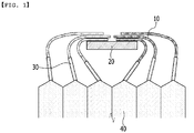
- FIG. 1 is a view showing a state in which an electrode lead in a conventional battery module is connected to a busbar.
- the battery cell stack 40 was assembled with a busbar frame (not shown) mounted with a busbar 20, and electrode leads 10 formed to protrude from the battery cell stack were subjected to laser welding or the like with the busbar 20 mounted on the busbar frame, thereby adhering the electrode lead 10 and the busbar 20.
- the electrode leads 10 connected to the battery cell stack 40 should be bent and adhered to the busbar.
- a spring-back phenomenon may occur in which the bending of a previously bent electrode lead is restored to its original shape by elasticity.
- the bending of the electrode lead 10 may have to be manually performed due to damage of the electrode lead or the like, and, therefore, problems such as a decrease in the process automation rate and a decrease in the welding quality may occur.
- a battery module comprising: a battery cell stack in which a plurality of battery cells are stacked, electrode leads formed to protrude from the battery cell stack, a busbar electrically connected to the electrode leads, and a busbar frame on which the busbar is mounted, wherein the busbar is formed of a tongs part and a fixing part for connecting and fixing the tongs part, and wherein the electrode leads are mounted between the tongs parts of the busbar.
- the busbar frame may comprise a lower opening part corresponding to the fixed part of the busbar, and a locking part corresponding to an end of the tongs part of the busbar.
- the lower opening part may correspond to a structure in which the busbar frame is recessed.
- the tongs part of the busbar is formed of two clip parts extending from the fixing part, and a distance between the two clip parts may decrease toward the fixing part.
- the electrode leads may be in contact with the clip part at a portion closer to the fixing part than an end of the clip part.
- the electrode leads may be formed to protrude in the shape of a flat plate.
- the battery module further includes cell terraces respectively protruding from the battery cells adjacent to each other among the battery cells included in the battery cell stack, and the electrode leads may be formed to protrude from the cell terraces.
- the tongs part of the busbar may be in close contact with the flat surface of the electrode lead in a vertical direction.
- a method for manufacturing a battery module comprises the steps of: mounting a busbar in an opening part of a busbar frame, inserting an electrode lead between tongs parts of the busbar, closely adhering the busbar and the electrode lead through a jig, and removing the jig.
- the jig can be inserted between the busbar frame and the busbar to closely adhere the busbar and the electrode lead.
- an electrode lead of a flat plate is inserted into and mounted to a busbar, and thus, the electrode lead and the busbar can be adhered even without bending the electrode lead. Therefore, an adhesion strength between the electrode lead and the busbar and thus the reliability associated with the electrical connection resulting therefrom can be obtained.
- the automated process rate associated with production can be improved.
- the busbar and the electrode lead are brought into close contact through a jig to ensure a stable electrical connection between the electrode lead and the busbar.
- weight reduction of the busbar can be achieved through a thin clip-type busbar structure.
- terms such as first, second, and the like may be used to describe various components, and the terms are used only to discriminate one component from another component.
- FIGS. 2 to 3 a battery module according to one embodiment of the present invention will be described with reference to FIGS. 2 to 3 .
- FIG. 2 is a perspective view showing a battery module according to one embodiment of the present invention.
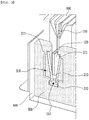
- FIG. 3 is a view showing a state in which an electrode lead of FIG. 2 is inserted into a busbar.
- a battery module basically includes a battery cell stack in which a plurality of battery cells 100 are stacked, electrode leads 120 formed to protrude from battery cells 100 included in the battery cell stack, a busbar 200 electrically connected to the electrode lead 120, and a busbar frame 300 on which the busbar 200 is mounted, and further includes a frame member 500 surrounding the battery cell stack and the busbar frame 300.
- the battery cell 100 is a secondary battery, and may be composed of a pouch-type secondary battery.
- a plurality of battery cells 100 may be stacked with each other so that they can be electrically connected to each other to form a battery cell stack.
- Each of the plurality of battery cells 100 may include an electrode assembly, a battery case, and an electrode lead 120 protruding from the electrode assembly.
- the electrode assembly may include a positive electrode plate, a negative electrode plate, and a separator.
- the battery case is to package the electrode assembly, and may be made of a laminate sheet including a resin layer and a metal layer.
- the battery case may include a case body and a cell terrace 110.
- the electrode lead 120 may be electrically connected to the electrode assembly.
- the configuration of the battery cell 100 described above is one embodiment, and the type of the battery cell 100 for configuring the battery cell stack may be variously modified.
- the electrode leads 120 may be formed of a flat plate and protrude to at least one side of the battery cell 100.
- the electrode leads 120 may be stacked and protruded in one direction, whereby a series or parallel connection between the electrode leads 120 may be possible.
- the electrode leads 120 may function as a battery terminal, and may be formed of a metal material such as copper or aluminum.
- the electrode lead 120 may be formed in various thicknesses, and may also be formed in various widths. The thickness or width of the electrode lead 120 may be manufactured differently according to the specifications of a secondary battery and a battery module.
- the busbar 200 may be in contact with the electrode leads 120 and be electrically connected thereto. Similar to the electrode leads 120, the busbar 200 may be formed of an electrically conductive metal material, such as copper or aluminum, for electrical connection with the electrode leads 120.
- busbar frame a busbar mounted thereon, and an electrode lead connected to the busbar will be described in detail with reference to FIGS. 2 to 5 .
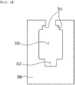
- FIG. 4 is a cross-sectional view of the busbar frame of FIG. 3 as viewed from the front.
- FIG. 5 is a cross-sectional view showing a state in which the busbar and the electrode lead are mounted in the busbar frame of FIG. 4 .
- a structure of the busbar frame 300 has an opening part 310 formed by partially opening an upper end.
- the opening part 310 includes a locking part 311 having a stepped shape based on the entrance of the opening part 310 at the upper portion thereof, and may further include a lower opening part 312 that is further recessed downwardly from the central portion of the opening part 310 at the lower portion thereof.
- the busbar 200 is configured of a tongs part 210 formed to insert the electrode lead 120 therein, and a fixing part 220 for connecting and fixing the tongs part 210.
- the tongs part 210 may be formed of two clip parts 211 and 212 respectively extending from the fixing part 220 in an upward diagonal direction. When the electrode lead 120 is inserted, the electrode lead 120 may be in contact with the inner surfaces of the two clip parts 211 and 212.
- the fixing part 220 may serve to connect and fix the tongs part 210 at the lower side thereof.
- the fixing part 220 is connected to the lower ends of the two clip parts 211 and 212, respectively, and according to one embodiment of the present invention, the fixing part 220 is formed to have a curvature downwardly from the tongs part 210, whereby the electrode lead 120 can be easily inserted into the tongs part 210 while elastically preventing deformation or movement of the tongs part 210 so that the tongs part 210 can be fixed.
- the busbar 200 as described above may be mounted in the opening part 310 formed in the busbar frame 300 provided on one side of the battery cell stack.
- the upper end of the tongs part 210 is positioned in the locking part 311 of the busbar frame 300
- the fixing part 220 is positioned in the lower opening part 312 of the busbar frame 300.
- the locking parts 311 are formed to be recessed at both upper vertex portions of the opening part 310, respectively, and the upper ends of the clip parts 211 and 212 on both sides of the tongs part 210 may be locked with both locking parts 311 and be mounted thereon, respectively, to support the busbar 200 from the upper side so as not to move.
- the lower opening part 312 is formed to correspond to a structure in which the busbar frame 300 is recessed in a downward direction, and the fixing part 220 may be inserted and mounted to support the busbar 200 from the lower side so as not to move.
- the busbar frame 300 may support the tongs part 210 of the busbar 200 from the upper left and right, respectively, while supporting the fixing parts 220 of the busbar from the lower center.
- the tongs part 210 and fixing part 220 of the busbar 200 are formed in the shape of a bent plate-like clip having a minimum width enough to be in contact with a flat surface of the electrode lead 120, whereby the unnecessary volume of the conventional busbar structure is reduced, and thus a lighter busbar device can be mounted on the battery module.
- the electrode leads 120 are electrically connected to the busbar 200, and for this purpose, the contact between the electrode leads 120 and the busbar 200 is required.
- the electrode leads 120 are formed to be stacked horizontally in the shape of a flat plate and to protrude from each of the plurality of battery cells 100, and the electrode leads 120 protruding in this way are inserted into the tongs part 210 of the busbar 200 and then can be contacted and fixed by the left and right clip parts 211 and 212 to be electrically connected with the busbar 200.
- the upper side of the busbar frame 300 is an open structure, and is formed so that the electrode leads 120 are easily inserted into the busbar frame 300; and the tongs part 210 of the busbar 200 mounted inside the busbar frame 300 is also formed such that the upper side is open. Therefore, the electrode leads 120 can be easily inserted into the tongs part 210 of the busbar 200 and mounted therein by using the upper opening structure of the busbar frame 300 and the busbar 200.
- the distance between the two clip parts 211 and 212 may decrease toward the lower fixing part 220 based on the distance between both upper ends of the clip parts 211 and 212. Therefore, the electrode leads 120 inserted from the upper side of the busbar 200 may be inserted downward along an insertion space formed by the two clip parts 211 and 212 of the tongs part 210, and the distance between the two clip parts 211 and 212 may decrease as it goes downward.
- the electrode leads 120 may be in contact with a portion between the two clip parts 211 and 212 formed closer to the fixing part 220 than the upper end of the two clip parts. More specifically, the flat surfaces of the electrode leads 120 correspond to the opposite surfaces of the two clip parts 211 and 212, and as a result, the tongs part 210 of the busbar 200 may be in close contact with the flat surface of the electrode leads 120 in a vertical direction.
- the narrower the distance between the locking parts 311 positioned at both upper ends of the busbar frame 300, the narrower the distance between the two clip portions 211, 212, and, thus, the contact position between the electrode leads 120 and the two clip parts 211 and 212 may move upward.
- the contact between the electrode leads 120 and the tongs part 210 of the busbar 200 can be continuously in close contact with each other, the contact between the two components can be made by welding adhesion.
- the electrode leads 120 are formed to protrude in the shape of a flat plate and are inserted and mounted in the clip-shaped busbar composed of the tongs part and the fixing part, as in the embodiment of the present invention, there is no need to bend the electrode leads 120 and, thus, the automation rate of the process can be improved; and there is no concern about the spring back phenomenon of bending and, thus, the reliability of the electrical connection between the electrode leads and the busbar can be secured.
- FIG. 6 is a cross-sectional view showing a state in which a jig is inserted into the busbar frame of FIG. 5 to closely adhere the busbar and the electrode lead.
- a busbar 200 is mounted on an opening part 310 of a busbar frame 300.
- a tongs part 210 of the busbar 200 may be mounted on a locking part 311 formed on both sides of the upper opening part of the busbar frame 300, and a fixing part 220 of the busbar 200 may be mounted on the lower opening part of the busbar frame 300.
- the mounting of the busbar 200 may be made through a jig 400.
- the electrode leads 120 are inserted between the tongs 210 of the busbar 200. Accordingly, the electrode leads 120 may be electrically connected to the busbar 200 on both sides.
- the busbar 200 and the electrode lead 120 are brought into close contact through the jig. As shown in FIG. 6 , the jig is inserted into the space between the busbar frame 300 and the busbar 200, so that the busbar 200 and the electrode lead 120 can be in close contact. By closely adhering the busbar 200 and the electrode lead 120, the reliability of the electrical connection between them can be secured.
- the jig 400 may be removed from the battery module.
Landscapes
- Chemical & Material Sciences (AREA)
- Chemical Kinetics & Catalysis (AREA)
- Electrochemistry (AREA)
- General Chemical & Material Sciences (AREA)
- Engineering & Computer Science (AREA)
- Manufacturing & Machinery (AREA)
- Connection Of Batteries Or Terminals (AREA)
- Battery Mounting, Suspending (AREA)
- Sealing Battery Cases Or Jackets (AREA)
Abstract
Description
- This application claims the benefit of
Korean Patent Application No. 10-2019-0030176 filed on March 15, 2019 - The present invention relates to a battery module and a method for manufacturing the same, and more particularly, to a battery module having a connection structure between an electrode lead and a busbar, and a method for manufacturing the same.
- A secondary battery has attracted much attention as an energy source in various products such as a mobile device and an electric vehicle. The secondary battery is a potent energy resource that can replace the use of existing products using fossil fuels, and is in the spotlight as an environment-friendly energy source because it does not generate by-products due to energy use.
- Recently, along with a continuous rise of the necessity for a large-capacity secondary battery structure, including the utilization of the secondary battery as an energy storage source, there is a growing demand for a battery pack of a multi-module structure which is an assembly of battery modules in which a plurality of secondary batteries are connected in series/parallel.
- Meanwhile, when a plurality of battery cells are connected in series/parallel to configure a battery pack, it is common to configure a battery module composed of at least one battery cell, and to configure a battery pack by using at least one of the battery modules and adding other components.
- The battery module includes a plurality of battery cells stacked together and a busbar electrically connecting electrode leads of the plurality of battery cells.
-
FIG. 1 is a view showing a state in which an electrode lead in a conventional battery module is connected to a busbar. - Referring to
FIG. 1 , conventionally, after stacking battery cells to form abattery cell stack 40, thebattery cell stack 40 was assembled with a busbar frame (not shown) mounted with abusbar 20, and electrode leads 10 formed to protrude from the battery cell stack were subjected to laser welding or the like with thebusbar 20 mounted on the busbar frame, thereby adhering theelectrode lead 10 and thebusbar 20. - However, as shown in
FIG. 1 , when assembling thebattery cell stack 40 with thebusbar 20, the electrode leads 10 connected to thebattery cell stack 40 should be bent and adhered to the busbar. In the bending process, however, there is a problem that a spring-back phenomenon may occur in which the bending of a previously bent electrode lead is restored to its original shape by elasticity. - Also, similarly, as shown in
FIG. 1 , when a plurality of electrode leads 10 are bent and adhered to thebusbar 20 side by side, the plurality of electrode leads 10 are bent while being overlapped and are adhered to the busbar. In this case, due to the interaction of the spring back phenomenon occurring between the electrode leads 10, and the position difference between the electrode leads 10 due to bending, a gap between the electrode leads occurs, and a difference in the degree of welding adhesion occurs according to the distance between theelectrode lead 10 and thebusbar 20; and, thus, the adhesion strength between theelectrode lead 10 and thebusbar 20 is lowered, which may cause an abnormality in electrical connectivity. - In addition, the bending of the
electrode lead 10 may have to be manually performed due to damage of the electrode lead or the like, and, therefore, problems such as a decrease in the process automation rate and a decrease in the welding quality may occur. - Therefore, it is an object of the present disclosure to provide a battery module having a connection structure between a busbar and an electrode lead that can improve the processability and reliability of an electrical connection between the electrode lead and the busbar, and a manufacturing method thereof.
- Technical problems to be solved by the present disclosure are not limited to the aforementioned technical problem, and other technical problems, which are not mentioned above, may be clearly understood from the following descriptions by those skilled in the art to which the present disclosure pertains.
- According to one embodiment of the present invention for realizing the above object, there is provided a battery module comprising: a battery cell stack in which a plurality of battery cells are stacked, electrode leads formed to protrude from the battery cell stack, a busbar electrically connected to the electrode leads, and a busbar frame on which the busbar is mounted, wherein the busbar is formed of a tongs part and a fixing part for connecting and fixing the tongs part, and wherein the electrode leads are mounted between the tongs parts of the busbar.
- The busbar frame may comprise a lower opening part corresponding to the fixed part of the busbar, and a locking part corresponding to an end of the tongs part of the busbar.
- The lower opening part may correspond to a structure in which the busbar frame is recessed.
- The tongs part of the busbar is formed of two clip parts extending from the fixing part, and a distance between the two clip parts may decrease toward the fixing part.
- The electrode leads may be in contact with the clip part at a portion closer to the fixing part than an end of the clip part.
- The electrode leads may be formed to protrude in the shape of a flat plate.
- The battery module further includes cell terraces respectively protruding from the battery cells adjacent to each other among the battery cells included in the battery cell stack, and the electrode leads may be formed to protrude from the cell terraces.
- The tongs part of the busbar may be in close contact with the flat surface of the electrode lead in a vertical direction.
- A method for manufacturing a battery module according to one embodiment of the present invention comprises the steps of: mounting a busbar in an opening part of a busbar frame, inserting an electrode lead between tongs parts of the busbar, closely adhering the busbar and the electrode lead through a jig, and removing the jig.
- In the step of closely adhering the busbar and the electrode lead, the jig can be inserted between the busbar frame and the busbar to closely adhere the busbar and the electrode lead.
- In a battery module according to one embodiment of the present invention, an electrode lead of a flat plate is inserted into and mounted to a busbar, and thus, the electrode lead and the busbar can be adhered even without bending the electrode lead. Therefore, an adhesion strength between the electrode lead and the busbar and thus the reliability associated with the electrical connection resulting therefrom can be obtained.
- Further, in the battery module according to one embodiment of the present invention, since a manual operation process required for the bending operation is no longer necessary, the automated process rate associated with production can be improved.
- In addition, in the battery module according to one embodiment of the present invention, the busbar and the electrode lead are brought into close contact through a jig to ensure a stable electrical connection between the electrode lead and the busbar.
- In addition, in the battery module according to one embodiment of the present invention, weight reduction of the busbar can be achieved through a thin clip-type busbar structure.
- The effects of the present invention are not limited to the above-mentioned effects and further effects not described above will be clearly understood by those skilled in the art.
-
-
FIG. 1 is a view showing a state in which an electrode lead in a conventional battery module is connected to a busbar. -
FIG. 2 is a perspective view showing a battery module according to one embodiment of the present invention. -
FIG. 3 is a view showing a state in which an electrode lead ofFIG. 2 is inserted into a busbar. -
FIG. 4 is a cross-sectional view of a busbar frame ofFIG. 3 as viewed from the front. -
FIG. 5 is a cross-sectional view showing a state in which a busbar and an electrode lead are mounted in a busbar frame ofFIG. 4 . -
FIG. 6 is a cross-sectional view showing a state in which a jig is inserted into a busbar frame ofFIG. 5 to closely adhere the busbar and the electrode lead. - It should be appreciated that the exemplary embodiments, which will be described below, are illustratively described to help understand the present disclosure, and the present disclosure may be variously modified to be carried out differently from the exemplary embodiments described herein. However, in the description of the present disclosure, the specific descriptions and illustrations of publicly known functions or constituent elements will be omitted when it is determined that the specific descriptions and illustrations may unnecessarily obscure the subject matter of the present disclosure. In addition, to help understand the present disclosure, the accompanying drawings are not illustrated based on actual scales, but parts of the constituent elements may be exaggerated in size.
- As used herein, terms such as first, second, and the like may be used to describe various components, and the terms are used only to discriminate one component from another component.
- Further, the terms used herein are used only to describe exemplary embodiments, and are not intended to limit the present disclosure. A singular expression includes a plural expression unless they have definitely opposite meanings in the context. It should be understood that the terms "comprise", "include", and "have" as used herein are intended to designate the presence of stated features, numbers, steps, constitutional elements, or combinations thereof, but it should be understood that they do not preclude a possibility of existence or addition of one or more other features, numbers, steps, constitutional elements, or combinations thereof.
- Hereinafter, a battery module according to one embodiment of the present invention will be described with reference to
FIGS. 2 to 3 . -
FIG. 2 is a perspective view showing a battery module according to one embodiment of the present invention.FIG. 3 is a view showing a state in which an electrode lead ofFIG. 2 is inserted into a busbar. - Referring to
FIGS. 2 and3 , a battery module according to one embodiment of the present invention basically includes a battery cell stack in which a plurality ofbattery cells 100 are stacked, electrode leads 120 formed to protrude frombattery cells 100 included in the battery cell stack, abusbar 200 electrically connected to theelectrode lead 120, and abusbar frame 300 on which thebusbar 200 is mounted, and further includes aframe member 500 surrounding the battery cell stack and thebusbar frame 300. - The
battery cell 100 is a secondary battery, and may be composed of a pouch-type secondary battery. A plurality ofbattery cells 100 may be stacked with each other so that they can be electrically connected to each other to form a battery cell stack. - Each of the plurality of
battery cells 100 may include an electrode assembly, a battery case, and anelectrode lead 120 protruding from the electrode assembly. The electrode assembly may include a positive electrode plate, a negative electrode plate, and a separator. The battery case is to package the electrode assembly, and may be made of a laminate sheet including a resin layer and a metal layer. The battery case may include a case body and acell terrace 110. Theelectrode lead 120 may be electrically connected to the electrode assembly. - The configuration of the
battery cell 100 described above is one embodiment, and the type of thebattery cell 100 for configuring the battery cell stack may be variously modified. - The electrode leads 120 may be formed of a flat plate and protrude to at least one side of the
battery cell 100. The electrode leads 120 may be stacked and protruded in one direction, whereby a series or parallel connection between the electrode leads 120 may be possible. The electrode leads 120 may function as a battery terminal, and may be formed of a metal material such as copper or aluminum. In addition, theelectrode lead 120 may be formed in various thicknesses, and may also be formed in various widths. The thickness or width of theelectrode lead 120 may be manufactured differently according to the specifications of a secondary battery and a battery module. - The
busbar 200 may be in contact with the electrode leads 120 and be electrically connected thereto. Similar to the electrode leads 120, thebusbar 200 may be formed of an electrically conductive metal material, such as copper or aluminum, for electrical connection with the electrode leads 120. - Hereinafter, in the battery module according to one embodiment of the present invention, a busbar frame, a busbar mounted thereon, and an electrode lead connected to the busbar will be described in detail with reference to
FIGS. 2 to 5 . -
FIG. 4 is a cross-sectional view of the busbar frame ofFIG. 3 as viewed from the front.FIG. 5 is a cross-sectional view showing a state in which the busbar and the electrode lead are mounted in the busbar frame ofFIG. 4 . - Referring to
FIG. 4 , a structure of thebusbar frame 300 according to the embodiment of the present invention has anopening part 310 formed by partially opening an upper end. Theopening part 310 includes a lockingpart 311 having a stepped shape based on the entrance of theopening part 310 at the upper portion thereof, and may further include alower opening part 312 that is further recessed downwardly from the central portion of theopening part 310 at the lower portion thereof. - Referring to
FIG. 5 , thebusbar 200 according to the present embodiment is configured of atongs part 210 formed to insert theelectrode lead 120 therein, and a fixingpart 220 for connecting and fixing thetongs part 210. - The
tongs part 210 may be formed of twoclip parts part 220 in an upward diagonal direction. When theelectrode lead 120 is inserted, theelectrode lead 120 may be in contact with the inner surfaces of the twoclip parts - The fixing
part 220 may serve to connect and fix thetongs part 210 at the lower side thereof. The fixingpart 220 is connected to the lower ends of the twoclip parts part 220 is formed to have a curvature downwardly from thetongs part 210, whereby theelectrode lead 120 can be easily inserted into thetongs part 210 while elastically preventing deformation or movement of thetongs part 210 so that thetongs part 210 can be fixed. - The
busbar 200 as described above may be mounted in theopening part 310 formed in thebusbar frame 300 provided on one side of the battery cell stack. In this case, the upper end of thetongs part 210 is positioned in the lockingpart 311 of thebusbar frame 300, and the fixingpart 220 is positioned in thelower opening part 312 of thebusbar frame 300. - The locking
parts 311 are formed to be recessed at both upper vertex portions of theopening part 310, respectively, and the upper ends of theclip parts tongs part 210 may be locked with both lockingparts 311 and be mounted thereon, respectively, to support thebusbar 200 from the upper side so as not to move. - The
lower opening part 312 is formed to correspond to a structure in which thebusbar frame 300 is recessed in a downward direction, and the fixingpart 220 may be inserted and mounted to support thebusbar 200 from the lower side so as not to move. - As a result, the
busbar frame 300 may support thetongs part 210 of thebusbar 200 from the upper left and right, respectively, while supporting the fixingparts 220 of the busbar from the lower center. - According to the embodiment of the present invention, the
tongs part 210 and fixingpart 220 of thebusbar 200 are formed in the shape of a bent plate-like clip having a minimum width enough to be in contact with a flat surface of theelectrode lead 120, whereby the unnecessary volume of the conventional busbar structure is reduced, and thus a lighter busbar device can be mounted on the battery module. - The electrode leads 120 are electrically connected to the
busbar 200, and for this purpose, the contact between the electrode leads 120 and thebusbar 200 is required. According to one embodiment of the present invention, the electrode leads 120 are formed to be stacked horizontally in the shape of a flat plate and to protrude from each of the plurality ofbattery cells 100, and the electrode leads 120 protruding in this way are inserted into thetongs part 210 of thebusbar 200 and then can be contacted and fixed by the left andright clip parts busbar 200. - The upper side of the
busbar frame 300 is an open structure, and is formed so that the electrode leads 120 are easily inserted into thebusbar frame 300; and thetongs part 210 of thebusbar 200 mounted inside thebusbar frame 300 is also formed such that the upper side is open. Therefore, the electrode leads 120 can be easily inserted into thetongs part 210 of thebusbar 200 and mounted therein by using the upper opening structure of thebusbar frame 300 and thebusbar 200. - The distance between the two
clip parts lower fixing part 220 based on the distance between both upper ends of theclip parts busbar 200 may be inserted downward along an insertion space formed by the twoclip parts tongs part 210, and the distance between the twoclip parts - Therefore, the electrode leads 120 may be in contact with a portion between the two
clip parts part 220 than the upper end of the two clip parts. More specifically, the flat surfaces of the electrode leads 120 correspond to the opposite surfaces of the twoclip parts tongs part 210 of thebusbar 200 may be in close contact with the flat surface of the electrode leads 120 in a vertical direction. - According to an embodiment, the narrower the distance between the locking
parts 311 positioned at both upper ends of thebusbar frame 300, the narrower the distance between the twoclip portions clip parts - According to an embodiment of the present invention, in order that the contact between the electrode leads 120 and the
tongs part 210 of thebusbar 200 can be continuously in close contact with each other, the contact between the two components can be made by welding adhesion. - When the electrode leads 120 are formed to protrude in the shape of a flat plate and are inserted and mounted in the clip-shaped busbar composed of the tongs part and the fixing part, as in the embodiment of the present invention, there is no need to bend the electrode leads 120 and, thus, the automation rate of the process can be improved; and there is no concern about the spring back phenomenon of bending and, thus, the reliability of the electrical connection between the electrode leads and the busbar can be secured.
-
FIG. 6 is a cross-sectional view showing a state in which a jig is inserted into the busbar frame ofFIG. 5 to closely adhere the busbar and the electrode lead. - Hereinafter, a method of manufacturing a battery module according to one embodiment of the present invention will be described with reference to
FIGS. 2 to 6 . - First, a
busbar 200 is mounted on anopening part 310 of abusbar frame 300. A tongspart 210 of thebusbar 200 may be mounted on alocking part 311 formed on both sides of the upper opening part of thebusbar frame 300, and a fixingpart 220 of thebusbar 200 may be mounted on the lower opening part of thebusbar frame 300. In this case, the mounting of thebusbar 200 may be made through ajig 400. - After the
busbar 200 is mounted on thebusbar frame 300, the electrode leads 120 are inserted between thetongs 210 of thebusbar 200. Accordingly, the electrode leads 120 may be electrically connected to thebusbar 200 on both sides. - After the
electrode lead 120 is inserted between thetongs 210 of thebusbar 200, thebusbar 200 and theelectrode lead 120 are brought into close contact through the jig. As shown inFIG. 6 , the jig is inserted into the space between thebusbar frame 300 and thebusbar 200, so that thebusbar 200 and theelectrode lead 120 can be in close contact. By closely adhering thebusbar 200 and theelectrode lead 120, the reliability of the electrical connection between them can be secured. - After the
busbar 200 and theelectrode lead 120 are brought into close contact through thejig 400, thejig 400 may be removed from the battery module. - Although the invention has been shown and described with reference to the preferred embodiments, the scope of the present disclosure is not limited thereto, and numerous other modifications and embodiments can be devised by those skilled in the art that will fall within the spirit and scope of the principles of the invention described in the appended claims. Further, these modified embodiments should not be understood individually from the technical spirit or perspective of the present disclosure.
-
- 100:
- battery cell
- 110:
- cell terrace
- 120:
- electrode lead
- 200:
- busbar
- 210:
- tongs part
- 211:
- first clip part
- 212:
- second clip part
- 220:
- fixing part
- 300:
- busbar frame
- 310:
- opening part
- 311:
- locking part
- 312:
- lower opening part
- 400:
- jig
Claims (11)
- A battery module comprising:a battery cell stack in which a plurality of battery cells are stacked;electrode leads formed to protrude from the battery cell stack;a busbar electrically connected to the electrode leads; anda busbar frame on which the busbar is mounted,wherein the busbar includes a tongs part and a fixing part for connecting and fixing the tongs part,wherein the electrode leads are positioned between the tongs parts of the busbar, andwherein the bus bar frame includes an opening part, a locking part formed at an upper side of the opening part to enable an upper end of the tongs part to be positioned, and a lower opening part formed at a lower side of the opening part to enable the fixing part to be positioned.
- The battery module of claim 1, wherein the locking part is formed to have a step on the upper side of the opening part, and the upper end of the tongs part is locked and mounted on the step of the locking part.
- The battery module of claim 1, wherein the lower opening part is formed to be recessed to the lower side of the opening part, and the fixing part is inserted and mounted in the lower opening part.
- The battery module of claim 1, wherein the tongs part of the busbar is formed of two clip parts extending from the fixing part, and a distance between the two clip parts decreases toward the fixing part.
- The battery module of claim 4, wherein the locking parts are respectively formed on both sides of the center of the opening part, and the upper ends of the two clip parts are respectively locked and mounted on the locking parts formed on both sides.
- The battery module of claim 4, wherein the electrode leads are in contact with the clip part at a portion closer to the fixing part than an end of the clip part.
- The battery module of claim 1, wherein the electrode leads are formed to protrude in the shape of a flat plate.
- The battery module of claim 7, wherein the battery module further includes cell terraces respectively protruding from the battery cells adjacent to each other among the battery cells included in the battery cell stack, and the electrode leads are formed to protrude from the cell terraces.
- The battery module of claim 8, wherein the tongs part of the busbar is in close contact with the flat surface of the electrode lead in a vertical direction.
- A method for manufacturing a battery module comprising the steps of:mounting a busbar in an opening part of a busbar frame;inserting an electrode lead between tongs parts of the busbar,closely adhering the busbar and the electrode lead through a jig, andremoving the jig.
- The method of claim 10, wherein the jig closely adhering the busbar and the electrode lead is inserted between the busbar frame and the busbar to closely adhere the busbar and the electrode lead.
Applications Claiming Priority (2)
| Application Number | Priority Date | Filing Date | Title |
|---|---|---|---|
| KR1020190030176A KR102750490B1 (en) | 2019-03-15 | 2019-03-15 | Battery module and manufacturing method thereof |
| PCT/KR2020/003534 WO2020189975A1 (en) | 2019-03-15 | 2020-03-13 | Battery module and manufacturing method therefor |
Publications (2)
| Publication Number | Publication Date |
|---|---|
| EP3920267A1 true EP3920267A1 (en) | 2021-12-08 |
| EP3920267A4 EP3920267A4 (en) | 2022-04-06 |
Family
ID=72520424
Family Applications (1)
| Application Number | Title | Priority Date | Filing Date |
|---|---|---|---|
| EP20774165.3A Pending EP3920267A4 (en) | 2019-03-15 | 2020-03-13 | BATTERY MODULE AND METHOD FOR MAKING IT |
Country Status (6)
| Country | Link |
|---|---|
| US (2) | US12266823B2 (en) |
| EP (1) | EP3920267A4 (en) |
| JP (2) | JP7372339B2 (en) |
| KR (2) | KR102750490B1 (en) |
| CN (1) | CN113678314A (en) |
| WO (1) | WO2020189975A1 (en) |
Cited By (2)
| Publication number | Priority date | Publication date | Assignee | Title |
|---|---|---|---|---|
| EP3926706A4 (en) * | 2019-03-26 | 2022-08-03 | LG Energy Solution, Ltd. | BATTERY MODULE AND METHOD OF MANUFACTURING IT |
| EP4401213A4 (en) * | 2022-11-28 | 2025-08-13 | Lg Energy Solution Ltd | BATTERY SUBMODULE |
Families Citing this family (3)
| Publication number | Priority date | Publication date | Assignee | Title |
|---|---|---|---|---|
| CN213243051U (en) * | 2020-11-04 | 2021-05-18 | 东莞市硅翔绝缘材料有限公司 | Soft-packaged battery cell connecting and signal collecting device |
| KR102945306B1 (en) | 2021-02-22 | 2026-03-30 | 에스케이온 주식회사 | Battery cell assembly and battery pack having thereof |
| KR20250122689A (en) | 2024-02-07 | 2025-08-14 | 주식회사 엘지에너지솔루션 | Battery cell assembly and method of assemlying the same |
Family Cites Families (20)
| Publication number | Priority date | Publication date | Assignee | Title |
|---|---|---|---|---|
| JP3971324B2 (en) * | 2003-02-25 | 2007-09-05 | 日本碍子株式会社 | Energizing terminal gripper and gripper drive hand |
| JP4757508B2 (en) | 2005-03-01 | 2011-08-24 | 日本電気株式会社 | Electrical device assembly |
| JP5285997B2 (en) | 2008-08-27 | 2013-09-11 | 矢崎総業株式会社 | Power supply |
| JP5225255B2 (en) * | 2009-12-01 | 2013-07-03 | 日本航空電子工業株式会社 | Battery connection device |
| JP2013105700A (en) * | 2011-11-16 | 2013-05-30 | Yazaki Corp | Power supply device |
| JP5623483B2 (en) | 2012-09-18 | 2014-11-12 | トヨタ自動車株式会社 | Battery, battery pack, battery manufacturing method |
| KR20140093424A (en) * | 2013-01-18 | 2014-07-28 | 타이코에이엠피(유) | Battery module |
| JP6134209B2 (en) * | 2013-06-14 | 2017-05-24 | 矢崎総業株式会社 | Battery pack |
| KR101509206B1 (en) * | 2013-07-23 | 2015-04-10 | (주)이티에이치 | Secondary battery charge and discharge jig with improved grippre exchange structure |
| US11128005B2 (en) * | 2013-07-30 | 2021-09-21 | Cps Technology Holdings Llc | Lithium ion battery with lead acid form factor |
| JP5672348B1 (en) * | 2013-08-28 | 2015-02-18 | 株式会社オートネットワーク技術研究所 | Wiring module |
| JP6475139B2 (en) * | 2015-10-02 | 2019-02-27 | タイコエレクトロニクスジャパン合同会社 | Battery connecting device and battery connecting device assembly |
| KR102056875B1 (en) | 2015-11-10 | 2019-12-17 | 주식회사 엘지화학 | Battery module and battery pack including the same |
| KR20170095072A (en) * | 2016-02-12 | 2017-08-22 | 주식회사 엘지화학 | Secondary battery and method for manufacturing the secondary battery |
| KR101903228B1 (en) | 2016-06-01 | 2018-10-01 | 엘지전자 주식회사 | Battery Pack |
| KR20180092064A (en) | 2017-02-08 | 2018-08-17 | 에이치엘그린파워 주식회사 | Sensing module for battery module and sensing assembly comprising this |
| KR102249457B1 (en) | 2017-05-16 | 2021-05-06 | 주식회사 엘지화학 | Battery module, battery pack including the same, and vehicle including the same |
| KR102212449B1 (en) * | 2017-05-22 | 2021-02-03 | 주식회사 엘지화학 | Battery module and battery pack including the same |
| KR102209767B1 (en) * | 2017-06-13 | 2021-01-28 | 주식회사 엘지화학 | Battery module with improved coupling structure between electrode lead and bus bar |
| KR102155888B1 (en) | 2017-09-11 | 2020-09-14 | 주식회사 엘지화학 | Laser welding jig and laser welding apparatus comprising the same |
-
2019
- 2019-03-15 KR KR1020190030176A patent/KR102750490B1/en active Active
-
2020
- 2020-03-13 CN CN202080021026.8A patent/CN113678314A/en active Pending
- 2020-03-13 WO PCT/KR2020/003534 patent/WO2020189975A1/en not_active Ceased
- 2020-03-13 JP JP2021550050A patent/JP7372339B2/en active Active
- 2020-03-13 US US17/437,697 patent/US12266823B2/en active Active
- 2020-03-13 EP EP20774165.3A patent/EP3920267A4/en active Pending
-
2023
- 2023-10-19 JP JP2023180588A patent/JP7691186B2/en active Active
-
2024
- 2024-12-31 KR KR1020240202295A patent/KR20250009947A/en active Pending
-
2025
- 2025-02-18 US US19/055,827 patent/US20250192376A1/en active Pending
Cited By (3)
| Publication number | Priority date | Publication date | Assignee | Title |
|---|---|---|---|---|
| EP3926706A4 (en) * | 2019-03-26 | 2022-08-03 | LG Energy Solution, Ltd. | BATTERY MODULE AND METHOD OF MANUFACTURING IT |
| US12586859B2 (en) | 2019-03-26 | 2026-03-24 | Lg Energy Solution, Ltd. | Battery module and method of manufacturing the same |
| EP4401213A4 (en) * | 2022-11-28 | 2025-08-13 | Lg Energy Solution Ltd | BATTERY SUBMODULE |
Also Published As
| Publication number | Publication date |
|---|---|
| US20250192376A1 (en) | 2025-06-12 |
| US20220158308A1 (en) | 2022-05-19 |
| EP3920267A4 (en) | 2022-04-06 |
| JP7691186B2 (en) | 2025-06-11 |
| KR102750490B1 (en) | 2025-01-03 |
| KR20250009947A (en) | 2025-01-20 |
| JP2023174909A (en) | 2023-12-08 |
| CN113678314A (en) | 2021-11-19 |
| JP7372339B2 (en) | 2023-10-31 |
| WO2020189975A1 (en) | 2020-09-24 |
| JP2022522343A (en) | 2022-04-18 |
| US12266823B2 (en) | 2025-04-01 |
| KR20200110082A (en) | 2020-09-23 |
Similar Documents
| Publication | Publication Date | Title |
|---|---|---|
| US20250192376A1 (en) | Battery Module and Manufacturing Method Thereof | |
| EP3690987B1 (en) | Unit module including busbar frame structure which can facilitate welding, and battery module including same | |
| EP2887427B1 (en) | Battery module with bus-bar holder | |
| EP3671902B1 (en) | Battery module having bus bar assembly | |
| US11923564B2 (en) | Method for producing battery module | |
| US8597378B2 (en) | Reversible battery assembly and tooling for automated high volume production | |
| US11152671B2 (en) | Battery module and battery pack including the same | |
| KR20220012037A (en) | Battery module having a simple connection structure between cell lead and voltage sensing member and battery pack including the same | |
| KR20200108714A (en) | Inter connect board assembly and battery module including the same | |
| JP2007324004A (en) | Assembled battery and method of manufacturing the assembled battery | |
| US20210320362A1 (en) | Battery module and manufacturing method thereof | |
| CN110034269B (en) | Battery top cap subassembly, secondary cell and battery module | |
| CN106062994A (en) | Connection member and electricity storage module | |
| CN101689618B (en) | Prismatic accumulator | |
| CN212303843U (en) | Battery Assembly Components and Lithium-Ion Batteries | |
| KR102890284B1 (en) | Battery module and manufacturing method thereof | |
| EP4421967A1 (en) | Battery module comprising upper/lower-separable bus bar frame, and method for assembling same | |
| CN218039718U (en) | Current collecting component, end cover assembly, battery module and electric equipment | |
| KR102834586B1 (en) | Bus bar assembly and method for manufacturing thereof | |
| CN217306611U (en) | Battery device | |
| US20260051635A1 (en) | Direct foil to terminal connection designs for prismatic cell manufacturing | |
| US20260106332A1 (en) | Busbar assembly | |
| KR20170077536A (en) | Battery pack | |
| KR20260019780A (en) | Busbar, Battery Assembly Including The Busbar, And Manufacturing Method of The Battery Assembly |
Legal Events
| Date | Code | Title | Description |
|---|---|---|---|
| STAA | Information on the status of an ep patent application or granted ep patent |
Free format text: STATUS: THE INTERNATIONAL PUBLICATION HAS BEEN MADE |
|
| PUAI | Public reference made under article 153(3) epc to a published international application that has entered the european phase |
Free format text: ORIGINAL CODE: 0009012 |
|
| STAA | Information on the status of an ep patent application or granted ep patent |
Free format text: STATUS: REQUEST FOR EXAMINATION WAS MADE |
|
| 17P | Request for examination filed |
Effective date: 20210902 |
|
| AK | Designated contracting states |
Kind code of ref document: A1 Designated state(s): AL AT BE BG CH CY CZ DE DK EE ES FI FR GB GR HR HU IE IS IT LI LT LU LV MC MK MT NL NO PL PT RO RS SE SI SK SM TR |
|
| RAP3 | Party data changed (applicant data changed or rights of an application transferred) |
Owner name: LG ENERGY SOLUTION, LTD. |
|
| A4 | Supplementary search report drawn up and despatched |
Effective date: 20220307 |
|
| RIC1 | Information provided on ipc code assigned before grant |
Ipc: H01M 50/567 20210101ALI20220301BHEP Ipc: H01M 50/553 20210101ALI20220301BHEP Ipc: H01M 50/50 20210101ALI20220301BHEP Ipc: H01M 50/178 20210101ALI20220301BHEP Ipc: H01M 50/517 20210101ALI20220301BHEP Ipc: H01M 50/516 20210101ALI20220301BHEP Ipc: H01M 50/514 20210101AFI20220301BHEP |
|
| DAV | Request for validation of the european patent (deleted) | ||
| DAX | Request for extension of the european patent (deleted) |