EP3919975B1 - Photographic lamp chuck compatible with different lamp holders - Google Patents
Photographic lamp chuck compatible with different lamp holders Download PDFInfo
- Publication number
- EP3919975B1 EP3919975B1 EP20815553.1A EP20815553A EP3919975B1 EP 3919975 B1 EP3919975 B1 EP 3919975B1 EP 20815553 A EP20815553 A EP 20815553A EP 3919975 B1 EP3919975 B1 EP 3919975B1
- Authority
- EP
- European Patent Office
- Prior art keywords
- insertion hole
- positioning
- photographic
- lamp
- inserting block
- Prior art date
- Legal status (The legal status is an assumption and is not a legal conclusion. Google has not performed a legal analysis and makes no representation as to the accuracy of the status listed.)
- Active
Links
Images



Classifications
-
- G—PHYSICS
- G03—PHOTOGRAPHY; CINEMATOGRAPHY; ANALOGOUS TECHNIQUES USING WAVES OTHER THAN OPTICAL WAVES; ELECTROGRAPHY; HOLOGRAPHY
- G03B—APPARATUS OR ARRANGEMENTS FOR TAKING PHOTOGRAPHS OR FOR PROJECTING OR VIEWING THEM; APPARATUS OR ARRANGEMENTS EMPLOYING ANALOGOUS TECHNIQUES USING WAVES OTHER THAN OPTICAL WAVES; ACCESSORIES THEREFOR
- G03B15/00—Special procedures for taking photographs; Apparatus therefor
- G03B15/02—Illuminating scene
- G03B15/06—Special arrangements of screening, diffusing, or reflecting devices, e.g. in studio
-
- G—PHYSICS
- G03—PHOTOGRAPHY; CINEMATOGRAPHY; ANALOGOUS TECHNIQUES USING WAVES OTHER THAN OPTICAL WAVES; ELECTROGRAPHY; HOLOGRAPHY
- G03B—APPARATUS OR ARRANGEMENTS FOR TAKING PHOTOGRAPHS OR FOR PROJECTING OR VIEWING THEM; APPARATUS OR ARRANGEMENTS EMPLOYING ANALOGOUS TECHNIQUES USING WAVES OTHER THAN OPTICAL WAVES; ACCESSORIES THEREFOR
- G03B15/00—Special procedures for taking photographs; Apparatus therefor
- G03B15/02—Illuminating scene
- G03B15/03—Combinations of cameras with lighting apparatus; Flash units
- G03B15/04—Combinations of cameras with non-electronic flash apparatus; Non-electronic flash units
- G03B15/0478—Combinations of photographic apparatus with percussion type flash ignition systems
- G03B15/0484—Constructional details of the flash apparatus
-
- F—MECHANICAL ENGINEERING; LIGHTING; HEATING; WEAPONS; BLASTING
- F21—LIGHTING
- F21V—FUNCTIONAL FEATURES OR DETAILS OF LIGHTING DEVICES OR SYSTEMS THEREOF; STRUCTURAL COMBINATIONS OF LIGHTING DEVICES WITH OTHER ARTICLES, NOT OTHERWISE PROVIDED FOR
- F21V17/00—Fastening of component parts of lighting devices, e.g. shades, globes, refractors, reflectors, filters, screens, grids or protective cages
- F21V17/02—Fastening of component parts of lighting devices, e.g. shades, globes, refractors, reflectors, filters, screens, grids or protective cages with provision for adjustment
-
- G—PHYSICS
- G03—PHOTOGRAPHY; CINEMATOGRAPHY; ANALOGOUS TECHNIQUES USING WAVES OTHER THAN OPTICAL WAVES; ELECTROGRAPHY; HOLOGRAPHY
- G03B—APPARATUS OR ARRANGEMENTS FOR TAKING PHOTOGRAPHS OR FOR PROJECTING OR VIEWING THEM; APPARATUS OR ARRANGEMENTS EMPLOYING ANALOGOUS TECHNIQUES USING WAVES OTHER THAN OPTICAL WAVES; ACCESSORIES THEREFOR
- G03B17/00—Details of cameras or camera bodies; Accessories therefor
- G03B17/56—Accessories
- G03B17/566—Accessory clips, holders, shoes to attach accessories to camera
Definitions
- the present disclosure relates to photography accessories, and more particularly to a photographic lamp chuck adapted to different lamp holders.
- the photographic lamp chuck is provided with an insertion hole, and the chuck is tightly mounted on the side wall of the flash lamp chuck through the insertion hole.
- the existing flash lamp holders such as rectangular lamp holders and circular lamp holders. Since the opening structure of the insertion hole of the existing chuck is fixed, the chuck can only be applied to flash lamp chucks that match the opening structure. As a result, the versatility of the chuck is not good, which is not conducive to market promotion.
- EP3070523 A1 discloses a photographic lamp chuck adapted to a first type of lamp holders for a softbox, comprising: a casing, on which a supporting member (6), a snap-fitting member and a light passage hole (4) are formed.
- the light passage hole (4) is a cylindrical hole and a flash lamp cap fixing device is formed therein.
- the flash lamp cap fixing device comprises a supporting platform (8) and a pressing plate (7) opposite to the supporting platform (8) and having an adjustable position relative to the supporting platform (8).
- the snap-fitting device for a softbox enables an on-camera flash lamp to use both an on-camera flash lamp folded softbox and a strobe flash lamp softbox, reducing expenses for a user.
- an object of the present disclosure is to provide a photographic lamp chuck adapted to lamp holders of different structures.
- the present disclosure provides a photographic lamp chuck adapted to different lamp holders in accordance with claims which follow.
- a positioning block is movably inserted in the insertion hole of a photographic lamp chuck adapted to different lamp holders of the present disclosure, and whether to mount the positioning block is determined according to the shape and structure of the flash lamp holder, so that the chuck can be mounted on the lamp holder with different shapes and structures, which greatly enhances the scope of the applicability of the chuck, and facilitates the market promotion of the product.
- orientations and positional relationships such as “center”, “longitudinal”, “transverse”, “length”, “width”, “thickness”, “upper”, “lower”, “front”, “back”, “left”, “right”, “vertical”, “horizontal”, “top”, “bottom”, “inner”, “outer”, “clockwise” and “counterclockwise”, is based on the orientations or positional relationships shown in the drawings, which is only for the convenience of describing and simplifying the description of the present disclosure, rather than indicating or implying that the device or element referred to have a specific orientation, or be constructed and operated in a specific orientation, and therefore it cannot be understood as a limitation of the present disclosure.
- first and second are only used for descriptive purposes, and cannot be understood as indicating or implying relative importance or implicitly indicating the number of indicated technical features. Therefore, the features defined with “first” and “second” may explicitly or implicitly include one or more of the features. In the description of the present disclosure, “multiple” means two or more than two, unless otherwise specifically defined.
- the terms “mount”, “connect”, and “joint” should be understood in a broad sense, for example, it can be a fixed connection, a detachable connection, or an integral connection. Or it can be a mechanical connection or an electrical connection. Or it can be a direct connection, or an indirect connection through an intermediate medium, and it can be an internal communication between two elements or the interaction relationship between two elements.
- the specific meaning of the above-mentioned terms in the present disclosure can be understood according to specific circumstances. Referring to Figs.
- a photographic lamp chuck adapted to different lamp holders of the present disclosure, including: a main chuck body 100, which is provided with an accessory mounting position used to mount photographic accessories, such as a soft box and a reflector, and is provided with a first insertion hole 101 for accommodating a circular lamp holder of the photographic lamp.
- the shape of the first insertion hole 101 is circular, and the first insertion hole 101 matches an outer side of the circular lamp holder, so that the circular lamp holder is inserted into the first insertion hole 101 to mount the chuck on the circular lamp holder.
- An inner wall of the first insertion hole 101 is provided with an arc-shaped positioning surface 103 and groove bodies 102, and the arc-shaped positioning surface 103 is covered with elastic material.
- the elastic material includes silica gel and rubber.
- a positioning inserting member 200 is movably inserted in the groove bodies 102.
- the positioning inserting member 200 is provided with a platform surface 201, and the platform surface is equipped with silica gel material.
- the platform surface 201 of the positioning inserting member 200 and the inner wall of the first insertion hole 101 enclose a second insertion hole 202.
- the second insertion hole 202 is used to accommodate the second type of photographic lamp holder. Since the bottom of a rectangular lamp holder is matched with the platform surface 201 of the positioning inserting member 200, the rectangular lamp holder can be inserted into the second insertion hole 202 to mount the chuck on the rectangular lamp holder.
- the positioning inserting member 200 is added to the circular first insertion hole 101 to form the second insertion hole 202.
- the first insertion hole 101 is matched with the circular lamp holder, and the second insertion hole 202 is matched with the rectangular lamp holder.
- the second insertion hole 202 is a part of the first insertion hole 101.
- whether to insert the positioning inset 200 is determined according to the shape of the lamp holder, so as to adapt to different lamp holder structures.
- the arc-shaped positioning surface and the platform surface are provided with silicone materials, so that the lamp holder is more firmly clamped.
- the positioning inserting member 200 is inserted into the first insertion hole 101 to be adapted to other types of lamp holders. Since the positioning inserting member 200 is mounted in the first insertion hole 101 in a plug-in form, the positioning inserting member 200 of different structures can be simply replaced to be adapted to different lamp holder structures.
- the positioning inserting member 200 may be in the shape of a flat plate, and both ends of the positioning inserting member 200 are inserted into the groove bodies 102 on the inner wall of the first insertion hole 101.
- the structure of the positioning inserting member 200 is simple and easy to produce.
- the platform surface 201 is arranged on one side of the positioning inserting member 200, and the other side of the positioning inserting member 200 is provided with an arc-shaped surface 204 matched with the inner wall of the first insertion hole 101. Therefore, the arc-shaped surface 204 on the positioning inserting member 200 is attached to the inner wall of the first insertion hole 101. Since the platform surface 201 on the other side is pressed against the bottom of the side surface of the lamp holder, it can effectively prevent the positioning inserting member 200 from deforming due to force.
- a photographic lamp chuck adapted to different lamp holders of the present disclosure, including: a main chuck body 100, which is provided with an accessory mounting position and is provided with a first insertion hole 101 for accommodating the first type of photographic lamp holder.
- the inner wall of the first insertion hole 101 is provided with a circular arc-shaped positioning surface 103 and groove bodies 102.
- a positioning inserting member 200 is movably inserted in the groove bodies 102, and the positioning inserting member is provided with a second positioning surface.
- the second positioning surface of the positioning inserting member and the inner wall of the first insertion hole 101 forms a second insertion hole 202, and the second insertion hole 202 is used for accommodating a second type of photographic lamp holder.
- the positioning inserting member 200 includes a first inserting block 210 and a second inserting block 220.
- the second inserting block 220 is movably mounted on the arc-shaped positioning surface 103 of the first insertion hole 101, and the second inserting block 220 is provided with a third positioning surface 221.
- the third positioning surface 221 and the inner wall of the first insertion hole 101 enclose a third insertion hole 205.
- the third insertion hole 205 is used for accommodating a third type of photographic lamp holder.
- the first inserting block 210 is inserted to the second inserting block 220, and the second positioning surface is arranged on the first inserting block 210.
- the positioning inserting member 200 includes at least two inserting blocks.
- the positioning inserting member 200 is composed of two inserting blocks, it includes: a first inserting block 210 and a second inserting block 220.
- the second inserting block 220 is inserted and fixed in the first insertion hole 101 by ribs.
- the second inserting block 220 and the inner wall of the first insertion hole 101 form a third insertion hole 205 for accommodating the third type of photography the lamp holder.
- Latching openings 223 are provided on the second insert block 220, and the first inserting block 210 are provided with latches 211 matched with the latching openings.
- the second positioning surface on the first inserting block 210 and the inner wall of the first insertion hole 101 enclose a second insertion hole 202 for accommodating the second type of photographic lamp holder.
- the shape of the first insertion hole 101 is circular
- the third positioning surface 221 of the second insertion block 220 is an arc surface
- the radian of the arc surface is different from the radian of the inner wall of the first insertion hole 101.
- the second positioning surface in the inserting block 210 is a platform surface 201. Therefore, the chuck can be applied to circular lamp holder with different diameters or rectangular lamp holders.
- the number of groove bodies 102 on the inner wall of the first insertion hole 101 is at least two, and the second inserting block 220 is provided with ribs 203 that cooperate with the groove bodies 102, so that the positioning inserting member 200 is arranged in the main chuck body 100 through the cooperation of the ribs 203 and the groove bodies 102, thereby facilitating the disassembly and assembly of the positioning inserting member 200 and adapting to different lamp holders.
- At least one pressing member 300 is arranged in the first insertion hole 101.
- the pressing member 300 is used for pressing the side surface of the lamp holder, so that the lamp chuck can be firmly arranged on the chuck.
- the pressing member 300 is provided with a concave arc-shaped part, and both sides of the arc-shaped part is provided with a positioning plane 302.
- the pressing member 300 is arranged at an upper part of the first insertion hole 101, and the positioning inserting member 200 is arranged at a bottom part of the first insertion hole 101.
- the platform surface 201 of the positioning inserting member 200 tightly presses the bottom surface of the lamp holder, and the positioning plane 302 on the pressing member 300 tightly presses the upper surface of the lamp holder, so that the rectangular lamp holder is clamped and fixed by the cooperation of the positioning inserting member 200 and the pressing member 300.
- the number of the pressing members 300 When the number of the pressing members 300 is two, they can be arranged on both sides of the first insertion hole 101 in a bilaterally symmetrical manner.
- the pressing member 300 is movably arranged on the main chuck body 100 through an adjusting screw 301.
- the user can adjust the position of the pressing member 300 in the insertion hole by adjusting the screw 301 to adapt to lamp holders of different sizes.
Landscapes
- Physics & Mathematics (AREA)
- General Physics & Mathematics (AREA)
- Engineering & Computer Science (AREA)
- General Engineering & Computer Science (AREA)
- Fastening Of Light Sources Or Lamp Holders (AREA)
- Accessories Of Cameras (AREA)
Description
- The present disclosure relates to photography accessories, and more particularly to a photographic lamp chuck adapted to different lamp holders.
- With the continuous improvement of people's living standards, the popularity of photography in people's daily lives is also increasing, so people have put forward higher requirement for photography effects. Therefore, the applications of various photography accessories are becoming more and more extensive. In order to add various photographic accessories to the flash, some chucks for mounting the photographic accessories on the outside of the flash appear on the market today.
- In the prior art, the photographic lamp chuck is provided with an insertion hole, and the chuck is tightly mounted on the side wall of the flash lamp chuck through the insertion hole. However, with the development of the flash lamp, there are various shapes and structures of the existing flash lamp holders, such as rectangular lamp holders and circular lamp holders. Since the opening structure of the insertion hole of the existing chuck is fixed, the chuck can only be applied to flash lamp chucks that match the opening structure. As a result, the versatility of the chuck is not good, which is not conducive to market promotion.
-
EP3070523 A1 discloses a photographic lamp chuck adapted to a first type of lamp holders for a softbox, comprising: a casing, on which a supporting member (6), a snap-fitting member and a light passage hole (4) are formed. The light passage hole (4) is a cylindrical hole and a flash lamp cap fixing device is formed therein. The flash lamp cap fixing device comprises a supporting platform (8) and a pressing plate (7) opposite to the supporting platform (8) and having an adjustable position relative to the supporting platform (8). The snap-fitting device for a softbox enables an on-camera flash lamp to use both an on-camera flash lamp folded softbox and a strobe flash lamp softbox, reducing expenses for a user. - In order to overcome the above-mentioned drawbacks, an object of the present disclosure is to provide a photographic lamp chuck adapted to lamp holders of different structures.
- Accordingly, the present disclosure provides a photographic lamp chuck adapted to different lamp holders in accordance with claims which follow.
- According to an aspect of embodiments of the present disclosure, there is provided a photographic lamp chuck adapted to different lamp according to the appended claims.
- A positioning block is movably inserted in the insertion hole of a photographic lamp chuck adapted to different lamp holders of the present disclosure, and whether to mount the positioning block is determined according to the shape and structure of the flash lamp holder, so that the chuck can be mounted on the lamp holder with different shapes and structures, which greatly enhances the scope of the applicability of the chuck, and facilitates the market promotion of the product.
- For ease of description, the present disclosure is described in detail with the following preferred embodiments and accompanying drawings.
-
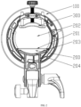
FIG. 1 is a schematic diagram of an overall structure of the present disclosure in a use state. -
FIG. 2 is a schematic diagram of a rear view of the present disclosure in a use state. -
FIG. 3 is a schematic diagram of an exploded structure of an embodiment of the present disclosure. -
FIG. 4 is a schematic diagram of an overall structure of the present disclosure in another use state. -
FIG. 5 is a schematic diagram of an overall structure of another embodiment of the present disclosure. -
FIG. 6 is a schematic diagram of an overall structure of another embodiment of the present disclosure. -
FIG. 7 is a schematic diagram of an overall structure of another embodiment of the present disclosure. -
FIG. 8 is a schematic diagram of an exploded structure of another embodiment of the present disclosure. - In order to make the object, technical solutions and advantages of the present disclosure clearer, the present disclosure is described below in detail with reference to the accompanying drawings and embodiments. It should be understood that the specific embodiments described herein are only used to explain the present disclosure, and are not used to limit the present disclosure.
- In the description of the present disclosure, it should be understood that the terms used to indicate orientations and positional relationships such as "center", "longitudinal", "transverse", "length", "width", "thickness", "upper", "lower", "front", "back", "left", "right", "vertical", "horizontal", "top", "bottom", "inner", "outer", "clockwise" and "counterclockwise", is based on the orientations or positional relationships shown in the drawings, which is only for the convenience of describing and simplifying the description of the present disclosure, rather than indicating or implying that the device or element referred to have a specific orientation, or be constructed and operated in a specific orientation, and therefore it cannot be understood as a limitation of the present disclosure. In addition, the terms "first" and "second" are only used for descriptive purposes, and cannot be understood as indicating or implying relative importance or implicitly indicating the number of indicated technical features. Therefore, the features defined with "first" and "second" may explicitly or implicitly include one or more of the features. In the description of the present disclosure, "multiple" means two or more than two, unless otherwise specifically defined.
- In the description of the present disclosure, it should be noted that, unless otherwise clearly stipulated and limited, the terms "mount", "connect", and "joint" should be understood in a broad sense, for example, it can be a fixed connection, a detachable connection, or an integral connection. Or it can be a mechanical connection or an electrical connection. Or it can be a direct connection, or an indirect connection through an intermediate medium, and it can be an internal communication between two elements or the interaction relationship between two elements. For those of ordinary skill in the art, the specific meaning of the above-mentioned terms in the present disclosure can be understood according to specific circumstances. Referring to
Figs. 1-4 , the following embodiment specifically describes a photographic lamp chuck adapted to different lamp holders of the present disclosure, including:
amain chuck body 100, which is provided with an accessory mounting position used to mount photographic accessories, such as a soft box and a reflector, and is provided with afirst insertion hole 101 for accommodating a circular lamp holder of the photographic lamp. The shape of thefirst insertion hole 101 is circular, and thefirst insertion hole 101 matches an outer side of the circular lamp holder, so that the circular lamp holder is inserted into thefirst insertion hole 101 to mount the chuck on the circular lamp holder. An inner wall of thefirst insertion hole 101 is provided with an arc-shaped positioning surface 103 andgroove bodies 102, and the arc-shaped positioning surface 103 is covered with elastic material. The elastic material includes silica gel and rubber. Apositioning inserting member 200 is movably inserted in thegroove bodies 102. The positioning insertingmember 200 is provided with aplatform surface 201, and the platform surface is equipped with silica gel material. Theplatform surface 201 of thepositioning inserting member 200 and the inner wall of thefirst insertion hole 101 enclose asecond insertion hole 202. Thesecond insertion hole 202 is used to accommodate the second type of photographic lamp holder. Since the bottom of a rectangular lamp holder is matched with theplatform surface 201 of thepositioning inserting member 200, the rectangular lamp holder can be inserted into thesecond insertion hole 202 to mount the chuck on the rectangular lamp holder. In this embodiment, thepositioning inserting member 200 is added to the circularfirst insertion hole 101 to form thesecond insertion hole 202. Thefirst insertion hole 101 is matched with the circular lamp holder, and thesecond insertion hole 202 is matched with the rectangular lamp holder. Thesecond insertion hole 202 is a part of thefirst insertion hole 101. In this embodiment, whether to insert thepositioning inset 200 is determined according to the shape of the lamp holder, so as to adapt to different lamp holder structures. - Moreover, the arc-shaped positioning surface and the platform surface are provided with silicone materials, so that the lamp holder is more firmly clamped.
- In this embodiment, the
positioning inserting member 200 is inserted into thefirst insertion hole 101 to be adapted to other types of lamp holders. Since thepositioning inserting member 200 is mounted in thefirst insertion hole 101 in a plug-in form, thepositioning inserting member 200 of different structures can be simply replaced to be adapted to different lamp holder structures. - Referring to
Fig. 5 , thepositioning inserting member 200 may be in the shape of a flat plate, and both ends of thepositioning inserting member 200 are inserted into thegroove bodies 102 on the inner wall of thefirst insertion hole 101. The structure of thepositioning inserting member 200 is simple and easy to produce. - Alternatively, the
platform surface 201 is arranged on one side of thepositioning inserting member 200, and the other side of thepositioning inserting member 200 is provided with an arc-shaped surface 204 matched with the inner wall of thefirst insertion hole 101. Therefore, the arc-shaped surface 204 on thepositioning inserting member 200 is attached to the inner wall of thefirst insertion hole 101. Since theplatform surface 201 on the other side is pressed against the bottom of the side surface of the lamp holder, it can effectively prevent the positioning insertingmember 200 from deforming due to force. - Referring to
Figs. 6-8 , the following another embodiment specifically describes a photographic lamp chuck adapted to different lamp holders of the present disclosure, including:
amain chuck body 100, which is provided with an accessory mounting position and is provided with afirst insertion hole 101 for accommodating the first type of photographic lamp holder. The inner wall of thefirst insertion hole 101 is provided with a circular arc-shaped positioning surface 103 andgroove bodies 102. Apositioning inserting member 200 is movably inserted in thegroove bodies 102, and the positioning inserting member is provided with a second positioning surface. The second positioning surface of the positioning inserting member and the inner wall of thefirst insertion hole 101 forms asecond insertion hole 202, and thesecond insertion hole 202 is used for accommodating a second type of photographic lamp holder. Thepositioning inserting member 200 includes a first insertingblock 210 and a second insertingblock 220. - The second inserting
block 220 is movably mounted on the arc-shapedpositioning surface 103 of thefirst insertion hole 101, and the second insertingblock 220 is provided with athird positioning surface 221. Thethird positioning surface 221 and the inner wall of thefirst insertion hole 101 enclose athird insertion hole 205. Thethird insertion hole 205 is used for accommodating a third type of photographic lamp holder. The first insertingblock 210 is inserted to the second insertingblock 220, and the second positioning surface is arranged on the first insertingblock 210. - In this embodiment, the
positioning inserting member 200 includes at least two inserting blocks. When thepositioning inserting member 200 is composed of two inserting blocks, it includes: a first insertingblock 210 and a second insertingblock 220. The second insertingblock 220 is inserted and fixed in thefirst insertion hole 101 by ribs. At this time, the second insertingblock 220 and the inner wall of thefirst insertion hole 101 form athird insertion hole 205 for accommodating the third type of photography the lamp holder. Latchingopenings 223 are provided on thesecond insert block 220, and the first insertingblock 210 are provided withlatches 211 matched with the latching openings. When the first insertingblock 210 is arranged on the upper surface of the second insertingblock 220, the second positioning surface on the first insertingblock 210 and the inner wall of thefirst insertion hole 101 enclose asecond insertion hole 202 for accommodating the second type of photographic lamp holder. - The shape of the
first insertion hole 101 is circular, thethird positioning surface 221 of thesecond insertion block 220 is an arc surface, and the radian of the arc surface is different from the radian of the inner wall of thefirst insertion hole 101. The second positioning surface in the insertingblock 210 is aplatform surface 201. Therefore, the chuck can be applied to circular lamp holder with different diameters or rectangular lamp holders. - In this embodiment, the number of
groove bodies 102 on the inner wall of thefirst insertion hole 101 is at least two, and the second insertingblock 220 is provided withribs 203 that cooperate with thegroove bodies 102, so that thepositioning inserting member 200 is arranged in themain chuck body 100 through the cooperation of theribs 203 and thegroove bodies 102, thereby facilitating the disassembly and assembly of thepositioning inserting member 200 and adapting to different lamp holders. - In this embodiment, at least one pressing
member 300 is arranged in thefirst insertion hole 101. The pressingmember 300 is used for pressing the side surface of the lamp holder, so that the lamp chuck can be firmly arranged on the chuck. - In this embodiment, the pressing
member 300 is provided with a concave arc-shaped part, and both sides of the arc-shaped part is provided with apositioning plane 302. The pressingmember 300 is arranged at an upper part of thefirst insertion hole 101, and thepositioning inserting member 200 is arranged at a bottom part of thefirst insertion hole 101. When a rectangular lamp holder is inserted into the insertion hole, theplatform surface 201 of thepositioning inserting member 200 tightly presses the bottom surface of the lamp holder, and thepositioning plane 302 on thepressing member 300 tightly presses the upper surface of the lamp holder, so that the rectangular lamp holder is clamped and fixed by the cooperation of thepositioning inserting member 200 and thepressing member 300. When a circular lamp holder is inserted into the insertion hole, the arc-shaped surface of the inner wall of the insertion hole abuts against the bottom surface of the lamp holder, and the arc-shaped part on thepressing member 300 tightly presses the upper surface of the lamp holder, so that the circular lamp holder is clamped and fixed by the cooperation of the inner wall of the insertion hole and thepressing member 300. - When the number of the
pressing members 300 is two, they can be arranged on both sides of thefirst insertion hole 101 in a bilaterally symmetrical manner. - In this embodiment, the pressing
member 300 is movably arranged on themain chuck body 100 through an adjustingscrew 301. The user can adjust the position of thepressing member 300 in the insertion hole by adjusting thescrew 301 to adapt to lamp holders of different sizes.
Claims (15)
- A photographic lamp chuck adapted to different lamp holders, comprising:a main chuck body (100),wherein the main chuck body (100) is provided with an accessory mounting position, and the main chuck body (100) is provided with a first insertion hole (101) for accommodating a first type of photographic lamp holder; wherein an inner wall of the first insertion hole (101) is provided with a positioning surface (103) characterized in that the positioning surface (103) is arc-shaped and adapted to the first type of photographic lamp holder and further characterized in that the inner wall of the first insertion hole (101) is provided with a groove body (102), and in that a positioning inserting member (200) is movably inserted to the groove body (102); wherein a second positioning surface is provided on the positioning inserting member (200), the second positioning surface of the positioning inserting member (200) and the inner wall of the first insertion hole (101) form a second insertion hole (202), and the second insertion hole (202) is used for accommodating a second type of photographic lamp holder.
- The photographic lamp chuck adapted to different lamp holders of claim 1, characterized in that, the positioning inserting member (200) is comprised of two or more inserting blocks, wherein the positioning inserting member (200) comprises a first inserting block (210) and a second inserting block (220); wherein the second inserting block (220) is movably mounted on the arc-shaped positioning surface (103) of the first insertion hole (101) and is provided with a third positioning surface (221), and the third positioning surface (221) and an inner wall of the first insertion hole (101) form a third insertion hole (205), which is used for accommodating a third type of photographic lamp holder; wherein the first inserting block (210) is inserted to the second inserting block (220), and the first inserting block (210) is provided with the second positioning surface.
- The photographic lamp chuck adapted to different lamp holders of claim 2, characterized in that, the number of the groove bodies (102) on the inner wall of the first insertion hole (101) is two or more, and the second inserting block (210) is provided with ribs (203) matched with the groove bodies (102) .
- The photographic lamp chuck adapted to different lamp holders of claim 2, characterized in that, the second inserting block (210) is provided with latching openings (223), and the first inserting block is provided with latches (211) matched with the latching openings (223).
- The photographic lamp chuck adapted to different lamp holders of claim 1, characterized in that, the second positioning surface is an upper surface of the positioning inserting member (200), and a bottom surface of the positioning inserting member (200) is an arc-shaped surface matched with the arc-shaped positioning surface of the first insertion hole (101).
- The photographic lamp chuck adapted to different lamp holders of claim 1, characterized in that, the number of the groove bodies (102) is two, the positioning inserting member (200) is in the shape of a flat plate, and each one of both ends of the positioning inserting member (200) is inserted into one groove body (102) on the inner wall of the first insertion hole (101).
- The photographic lamp chuck adapted to different lamp holders of claim 1 or 2, characterized in that, at least one pressing member (300) is arranged in the first insertion hole (105); the at least one pressing member (300) is provided with a concave arc-shaped part, and each of both sides of the arc-shaped part is provided with a positioning plane (302).
- The photographic lamp chuck adapted to different lamp holders of claim 7, characterized in that, the pressing member (300) is movably arranged on the main chuck body (100) through an adjusting screw (301).
- The photographic lamp chuck adapted to different lamp holders of claim 8, characterized in that, the pressing member (300) is arranged at an upper part of the first insertion hole (101), and the positioning inserting member (200) is arranged at a bottom part of the first insertion hole (101).
- The photographic lamp chuck adapted to different lamp holders of claim 1, characterized in that, the positioning inserting member (200) is provided with a platform surface (201), which is the second positioning surface, and both the arc-shaped positioning surface (103) and the platform surface (201) are provided with elastic materials.
- The photographic lamp chuck adapted to different lamp holders of claim 1, characterized in that, the positioning inserting member (200) has two ends, each of which is inserted into the groove body (102) on the inner wall of the first insertion hole (101).
- The photographic lamp chuck adapted to different lamp holders of claim 1, characterized in that, the positioning inserting member (200) comprises a first inserting block (210) and a second inserting block (220); wherein the second inserting block (220) is movably mounted on the arc-shaped positioning surface of the first insertion hole (101) and is provided with a third positioning surface (221), and the third positioning surface (221) and an inner wall of the first insertion hole (101) form a third insertion hole (205), which is used for accommodating a third type of photographic lamp holder; wherein the first inserting block (210) is inserted to the second inserting block (220), and the first inserting block (210) is provided with the second positioning surface (201).
- The photographic lamp chuck adapted to different lamp holders of claim 12, characterized in that, a bottom of the first inserting block (210) is provided with two latches (211), and each latch (211) is located on one end of the first inserting block (210), wherein the second inserting block (220) is provided with two latching openings (223), and each latch (211) is matched with one of the two latching openings (223).
- The photographic lamp chuck adapted to different lamp holders of claim 12, characterized in that, the number of the groove bodies (102) on the inner wall of the first insertion hole (101) is two, and the second inserting block (220) is provided with two ribs (203) matched with the groove bodies (102).
- The photographic lamp chuck adapted to different lamp holders of claim 2, characterized in that, the shape of the first insertion hole (101) is circular, the third positioning surface (221) of the second insertion block (220) is an arc surface, and the radian of the arc surface is different from the radian of the inner wall of the first insertion hole (101).
Applications Claiming Priority (2)
| Application Number | Priority Date | Filing Date | Title |
|---|---|---|---|
| CN201920786082.5U CN209821570U (en) | 2019-05-28 | 2019-05-28 | A photographic lamp chuck compatible with different lamp heads |
| PCT/CN2020/092399 WO2020238916A1 (en) | 2019-05-28 | 2020-05-26 | Photographic lamp chuck compatible with different lamp holders |
Publications (4)
| Publication Number | Publication Date |
|---|---|
| EP3919975A1 EP3919975A1 (en) | 2021-12-08 |
| EP3919975A4 EP3919975A4 (en) | 2022-04-06 |
| EP3919975C0 EP3919975C0 (en) | 2024-08-14 |
| EP3919975B1 true EP3919975B1 (en) | 2024-08-14 |
Family
ID=68883944
Family Applications (1)
| Application Number | Title | Priority Date | Filing Date |
|---|---|---|---|
| EP20815553.1A Active EP3919975B1 (en) | 2019-05-28 | 2020-05-26 | Photographic lamp chuck compatible with different lamp holders |
Country Status (5)
| Country | Link |
|---|---|
| US (1) | US11803103B2 (en) |
| EP (1) | EP3919975B1 (en) |
| CN (1) | CN209821570U (en) |
| MA (1) | MA54883A (en) |
| WO (1) | WO2020238916A1 (en) |
Families Citing this family (2)
| Publication number | Priority date | Publication date | Assignee | Title |
|---|---|---|---|---|
| CN209821570U (en) * | 2019-05-28 | 2019-12-20 | 深圳市神牛摄影器材有限公司 | A photographic lamp chuck compatible with different lamp heads |
| USD1102511S1 (en) * | 2021-09-27 | 2025-11-18 | Jianwu Jiang | Camera mount |
Family Cites Families (13)
| Publication number | Priority date | Publication date | Assignee | Title |
|---|---|---|---|---|
| US9300847B2 (en) * | 2013-01-25 | 2016-03-29 | Roy Lique | Digital camera lens guard and use extender |
| JP6304930B2 (en) * | 2013-02-21 | 2018-04-04 | キヤノン株式会社 | Adapter for optical accessories |
| CN203422545U (en) * | 2013-11-14 | 2014-02-05 | 深圳市神牛摄影器材有限公司 | Soft light box clamping device with on-camera flash lamp holder fixing part |
| CN104730806A (en) * | 2015-03-25 | 2015-06-24 | 潘宁乐 | Flash lamp fixing frame structure |
| US10481471B2 (en) * | 2015-09-08 | 2019-11-19 | Godox Photo Equipment Co., Ltd | Soft box |
| WO2019054938A1 (en) | 2017-09-18 | 2019-03-21 | Profoto Aktiebolag | A flash housing for emitting flash light for photographic purposes and a method performed in a flash housing |
| CN207457669U (en) * | 2017-10-10 | 2018-06-05 | 合肥路之达智能科技有限公司 | A kind of flash bracket for being conveniently adjusted angle |
| CN107859919A (en) | 2017-10-15 | 2018-03-30 | 王欣宇 | A kind of special reading lighting lamp in students' dormitory |
| CN108036217B (en) | 2018-02-02 | 2020-07-03 | 锡华军 | Clinical lighting device that uses of otolaryngology |
| US10345682B1 (en) * | 2018-04-16 | 2019-07-09 | Panavision International, L.P. | Variable diameter mounting attachment |
| US11215906B2 (en) * | 2018-06-11 | 2022-01-04 | Mgmd Brainpower Llc | Camera accessory housing device |
| KR102148263B1 (en) * | 2019-01-15 | 2020-08-26 | 고영국 | Universal Fixing Device |
| CN209821570U (en) | 2019-05-28 | 2019-12-20 | 深圳市神牛摄影器材有限公司 | A photographic lamp chuck compatible with different lamp heads |
-
2019
- 2019-05-28 CN CN201920786082.5U patent/CN209821570U/en active Active
-
2020
- 2020-05-26 WO PCT/CN2020/092399 patent/WO2020238916A1/en not_active Ceased
- 2020-05-26 MA MA054883A patent/MA54883A/en unknown
- 2020-05-26 EP EP20815553.1A patent/EP3919975B1/en active Active
- 2020-05-26 US US17/310,938 patent/US11803103B2/en active Active
Also Published As
| Publication number | Publication date |
|---|---|
| MA54883A (en) | 2022-04-06 |
| EP3919975A4 (en) | 2022-04-06 |
| US11803103B2 (en) | 2023-10-31 |
| EP3919975A1 (en) | 2021-12-08 |
| EP3919975C0 (en) | 2024-08-14 |
| CN209821570U (en) | 2019-12-20 |
| WO2020238916A1 (en) | 2020-12-03 |
| US20220155657A1 (en) | 2022-05-19 |
Similar Documents
| Publication | Publication Date | Title |
|---|---|---|
| US11803103B2 (en) | Photographic lamp chuck compatible with different lamp holders | |
| US7238042B2 (en) | Support assembly for portable device | |
| CN208224691U (en) | The photoflash of accessory connector and replaceable bayonet | |
| WO2022011945A1 (en) | Storage assembly and device assembly of handheld gimbal camera | |
| CN220102973U (en) | Line lamp mounting structure | |
| CN223939296U (en) | A foldable reading lamp | |
| JP2004146277A (en) | Lamp socket and luminaire using it | |
| CN222047213U (en) | Connecting arm with fill light and selfie stick thereof | |
| JP3754273B2 (en) | Lamp socket and luminaire | |
| CN223566017U (en) | Shooting aids and shooting aid devices | |
| JP2003059309A (en) | lighting equipment | |
| CN219606633U (en) | Telescopic component and shooting support | |
| CN219775366U (en) | Telescopic component | |
| CN208092395U (en) | Easily contained light compensating lamp | |
| CN216794167U (en) | Plug converter with charging data line | |
| CN220076152U (en) | Fixer, support frame and hanging seat of charging gun | |
| CN218122432U (en) | stick lights | |
| CN210771816U (en) | Pocket hose lamp | |
| CN222736215U (en) | Camera housing and camera | |
| CN223437094U (en) | A mobile phone shooting aid | |
| CN217607943U (en) | Earphone box and earphone storage device | |
| CN213146021U (en) | Unmanned vehicle's camera mount and unmanned vehicle | |
| CN110557544A (en) | Cloud platform camera capable of supplying power and transmitting data through mobile phone data interface | |
| CN217874904U (en) | Clamping device and shooting auxiliary assembly | |
| KR100258763B1 (en) | Charger pile of wireless terminal |
Legal Events
| Date | Code | Title | Description |
|---|---|---|---|
| STAA | Information on the status of an ep patent application or granted ep patent |
Free format text: STATUS: THE INTERNATIONAL PUBLICATION HAS BEEN MADE |
|
| PUAI | Public reference made under article 153(3) epc to a published international application that has entered the european phase |
Free format text: ORIGINAL CODE: 0009012 |
|
| STAA | Information on the status of an ep patent application or granted ep patent |
Free format text: STATUS: REQUEST FOR EXAMINATION WAS MADE |
|
| 17P | Request for examination filed |
Effective date: 20210901 |
|
| AK | Designated contracting states |
Kind code of ref document: A1 Designated state(s): AL AT BE BG CH CY CZ DE DK EE ES FI FR GB GR HR HU IE IS IT LI LT LU LV MC MK MT NL NO PL PT RO RS SE SI SK SM TR |
|
| REG | Reference to a national code |
Ref country code: DE Ref legal event code: R079 Free format text: PREVIOUS MAIN CLASS: G03B0015000000 Ipc: G03B0015060000 Ref document number: 602020035886 Country of ref document: DE |
|
| A4 | Supplementary search report drawn up and despatched |
Effective date: 20220309 |
|
| RIC1 | Information provided on ipc code assigned before grant |
Ipc: G03B 15/06 20210101AFI20220302BHEP |
|
| GRAP | Despatch of communication of intention to grant a patent |
Free format text: ORIGINAL CODE: EPIDOSNIGR1 |
|
| STAA | Information on the status of an ep patent application or granted ep patent |
Free format text: STATUS: GRANT OF PATENT IS INTENDED |
|
| INTG | Intention to grant announced |
Effective date: 20240328 |
|
| GRAS | Grant fee paid |
Free format text: ORIGINAL CODE: EPIDOSNIGR3 |
|
| GRAA | (expected) grant |
Free format text: ORIGINAL CODE: 0009210 |
|
| STAA | Information on the status of an ep patent application or granted ep patent |
Free format text: STATUS: THE PATENT HAS BEEN GRANTED |
|
| AK | Designated contracting states |
Kind code of ref document: B1 Designated state(s): AL AT BE BG CH CY CZ DE DK EE ES FI FR GB GR HR HU IE IS IT LI LT LU LV MC MK MT NL NO PL PT RO RS SE SI SK SM TR |
|
| REG | Reference to a national code |
Ref country code: GB Ref legal event code: FG4D |
|
| REG | Reference to a national code |
Ref country code: CH Ref legal event code: EP |
|
| REG | Reference to a national code |
Ref country code: DE Ref legal event code: R096 Ref document number: 602020035886 Country of ref document: DE |
|
| REG | Reference to a national code |
Ref country code: IE Ref legal event code: FG4D |
|
| U01 | Request for unitary effect filed |
Effective date: 20240902 |
|
| U07 | Unitary effect registered |
Designated state(s): AT BE BG DE DK EE FI FR IT LT LU LV MT NL PT RO SE SI Effective date: 20240913 |
|
| PG25 | Lapsed in a contracting state [announced via postgrant information from national office to epo] |
Ref country code: NO Free format text: LAPSE BECAUSE OF FAILURE TO SUBMIT A TRANSLATION OF THE DESCRIPTION OR TO PAY THE FEE WITHIN THE PRESCRIBED TIME-LIMIT Effective date: 20241114 |
|
| PG25 | Lapsed in a contracting state [announced via postgrant information from national office to epo] |
Ref country code: GR Free format text: LAPSE BECAUSE OF FAILURE TO SUBMIT A TRANSLATION OF THE DESCRIPTION OR TO PAY THE FEE WITHIN THE PRESCRIBED TIME-LIMIT Effective date: 20241115 Ref country code: PL Free format text: LAPSE BECAUSE OF FAILURE TO SUBMIT A TRANSLATION OF THE DESCRIPTION OR TO PAY THE FEE WITHIN THE PRESCRIBED TIME-LIMIT Effective date: 20240814 |
|
| PG25 | Lapsed in a contracting state [announced via postgrant information from national office to epo] |
Ref country code: IS Free format text: LAPSE BECAUSE OF FAILURE TO SUBMIT A TRANSLATION OF THE DESCRIPTION OR TO PAY THE FEE WITHIN THE PRESCRIBED TIME-LIMIT Effective date: 20241214 |
|
| PG25 | Lapsed in a contracting state [announced via postgrant information from national office to epo] |
Ref country code: HR Free format text: LAPSE BECAUSE OF FAILURE TO SUBMIT A TRANSLATION OF THE DESCRIPTION OR TO PAY THE FEE WITHIN THE PRESCRIBED TIME-LIMIT Effective date: 20240814 |
|
| PG25 | Lapsed in a contracting state [announced via postgrant information from national office to epo] |
Ref country code: RS Free format text: LAPSE BECAUSE OF FAILURE TO SUBMIT A TRANSLATION OF THE DESCRIPTION OR TO PAY THE FEE WITHIN THE PRESCRIBED TIME-LIMIT Effective date: 20241114 Ref country code: ES Free format text: LAPSE BECAUSE OF FAILURE TO SUBMIT A TRANSLATION OF THE DESCRIPTION OR TO PAY THE FEE WITHIN THE PRESCRIBED TIME-LIMIT Effective date: 20240814 |
|
| PG25 | Lapsed in a contracting state [announced via postgrant information from national office to epo] |
Ref country code: RS Free format text: LAPSE BECAUSE OF FAILURE TO SUBMIT A TRANSLATION OF THE DESCRIPTION OR TO PAY THE FEE WITHIN THE PRESCRIBED TIME-LIMIT Effective date: 20241114 Ref country code: PL Free format text: LAPSE BECAUSE OF FAILURE TO SUBMIT A TRANSLATION OF THE DESCRIPTION OR TO PAY THE FEE WITHIN THE PRESCRIBED TIME-LIMIT Effective date: 20240814 Ref country code: NO Free format text: LAPSE BECAUSE OF FAILURE TO SUBMIT A TRANSLATION OF THE DESCRIPTION OR TO PAY THE FEE WITHIN THE PRESCRIBED TIME-LIMIT Effective date: 20241114 Ref country code: IS Free format text: LAPSE BECAUSE OF FAILURE TO SUBMIT A TRANSLATION OF THE DESCRIPTION OR TO PAY THE FEE WITHIN THE PRESCRIBED TIME-LIMIT Effective date: 20241214 Ref country code: HR Free format text: LAPSE BECAUSE OF FAILURE TO SUBMIT A TRANSLATION OF THE DESCRIPTION OR TO PAY THE FEE WITHIN THE PRESCRIBED TIME-LIMIT Effective date: 20240814 Ref country code: GR Free format text: LAPSE BECAUSE OF FAILURE TO SUBMIT A TRANSLATION OF THE DESCRIPTION OR TO PAY THE FEE WITHIN THE PRESCRIBED TIME-LIMIT Effective date: 20241115 Ref country code: ES Free format text: LAPSE BECAUSE OF FAILURE TO SUBMIT A TRANSLATION OF THE DESCRIPTION OR TO PAY THE FEE WITHIN THE PRESCRIBED TIME-LIMIT Effective date: 20240814 |
|
| PG25 | Lapsed in a contracting state [announced via postgrant information from national office to epo] |
Ref country code: SM Free format text: LAPSE BECAUSE OF FAILURE TO SUBMIT A TRANSLATION OF THE DESCRIPTION OR TO PAY THE FEE WITHIN THE PRESCRIBED TIME-LIMIT Effective date: 20240814 |
|
| PG25 | Lapsed in a contracting state [announced via postgrant information from national office to epo] |
Ref country code: CZ Free format text: LAPSE BECAUSE OF FAILURE TO SUBMIT A TRANSLATION OF THE DESCRIPTION OR TO PAY THE FEE WITHIN THE PRESCRIBED TIME-LIMIT Effective date: 20240814 |
|
| PG25 | Lapsed in a contracting state [announced via postgrant information from national office to epo] |
Ref country code: SK Free format text: LAPSE BECAUSE OF FAILURE TO SUBMIT A TRANSLATION OF THE DESCRIPTION OR TO PAY THE FEE WITHIN THE PRESCRIBED TIME-LIMIT Effective date: 20240814 |
|
| U20 | Renewal fee for the european patent with unitary effect paid |
Year of fee payment: 6 Effective date: 20250508 |
|
| VS25 | Lapsed in a validation state [announced via postgrant information from nat. office to epo] |
Ref country code: MD Free format text: LAPSE BECAUSE OF FAILURE TO SUBMIT A TRANSLATION OF THE DESCRIPTION OR TO PAY THE FEE WITHIN THE PRESCRIBED TIME-LIMIT Effective date: 20240814 |
|
| PLBE | No opposition filed within time limit |
Free format text: ORIGINAL CODE: 0009261 |
|
| STAA | Information on the status of an ep patent application or granted ep patent |
Free format text: STATUS: NO OPPOSITION FILED WITHIN TIME LIMIT |
|
| 26N | No opposition filed |
Effective date: 20250515 |
|
| REG | Reference to a national code |
Ref country code: CH Ref legal event code: H13 Free format text: ST27 STATUS EVENT CODE: U-0-0-H10-H13 (AS PROVIDED BY THE NATIONAL OFFICE) Effective date: 20251223 |
|
| PG25 | Lapsed in a contracting state [announced via postgrant information from national office to epo] |
Ref country code: CH Free format text: LAPSE BECAUSE OF NON-PAYMENT OF DUE FEES Effective date: 20250531 |
|
| GBPC | Gb: european patent ceased through non-payment of renewal fee |
Effective date: 20250526 |
|
| PG25 | Lapsed in a contracting state [announced via postgrant information from national office to epo] |
Ref country code: MC Free format text: LAPSE BECAUSE OF FAILURE TO SUBMIT A TRANSLATION OF THE DESCRIPTION OR TO PAY THE FEE WITHIN THE PRESCRIBED TIME-LIMIT Effective date: 20240814 |
|
| PG25 | Lapsed in a contracting state [announced via postgrant information from national office to epo] |
Ref country code: GB Free format text: LAPSE BECAUSE OF NON-PAYMENT OF DUE FEES Effective date: 20250526 |
|
| PG25 | Lapsed in a contracting state [announced via postgrant information from national office to epo] |
Ref country code: IE Free format text: LAPSE BECAUSE OF NON-PAYMENT OF DUE FEES Effective date: 20250526 |
|
| VS25 | Lapsed in a validation state [announced via postgrant information from nat. office to epo] |
Ref country code: MA Free format text: LAPSE BECAUSE OF FAILURE TO SUBMIT A TRANSLATION OF THE DESCRIPTION OR TO PAY THE FEE WITHIN THE PRESCRIBED TIME-LIMIT; INVALID AB INITIO Effective date: 20200526 |