EP3919900A1 - Hazardous gas monitoring system - Google Patents
Hazardous gas monitoring system Download PDFInfo
- Publication number
- EP3919900A1 EP3919900A1 EP21174193.9A EP21174193A EP3919900A1 EP 3919900 A1 EP3919900 A1 EP 3919900A1 EP 21174193 A EP21174193 A EP 21174193A EP 3919900 A1 EP3919900 A1 EP 3919900A1
- Authority
- EP
- European Patent Office
- Prior art keywords
- monitoring system
- gas monitoring
- flow
- line
- sensing
- Prior art date
- Legal status (The legal status is an assumption and is not a legal conclusion. Google has not performed a legal analysis and makes no representation as to the accuracy of the status listed.)
- Pending
Links
Images




Classifications
-
- G—PHYSICS
- G01—MEASURING; TESTING
- G01N—INVESTIGATING OR ANALYSING MATERIALS BY DETERMINING THEIR CHEMICAL OR PHYSICAL PROPERTIES
- G01N33/00—Investigating or analysing materials by specific methods not covered by groups G01N1/00 - G01N31/00
- G01N33/0004—Gaseous mixtures, e.g. polluted air
- G01N33/0009—General constructional details of gas analysers, e.g. portable test equipment
-
- G—PHYSICS
- G01—MEASURING; TESTING
- G01N—INVESTIGATING OR ANALYSING MATERIALS BY DETERMINING THEIR CHEMICAL OR PHYSICAL PROPERTIES
- G01N33/00—Investigating or analysing materials by specific methods not covered by groups G01N1/00 - G01N31/00
- G01N33/0004—Gaseous mixtures, e.g. polluted air
-
- F—MECHANICAL ENGINEERING; LIGHTING; HEATING; WEAPONS; BLASTING
- F02—COMBUSTION ENGINES; HOT-GAS OR COMBUSTION-PRODUCT ENGINE PLANTS
- F02C—GAS-TURBINE PLANTS; AIR INTAKES FOR JET-PROPULSION PLANTS; CONTROLLING FUEL SUPPLY IN AIR-BREATHING JET-PROPULSION PLANTS
- F02C7/00—Features, components parts, details or accessories, not provided for in, or of interest apart form groups F02C1/00 - F02C6/00; Air intakes for jet-propulsion plants
- F02C7/24—Heat or noise insulation
- F02C7/25—Fire protection or prevention
-
- C—CHEMISTRY; METALLURGY
- C10—PETROLEUM, GAS OR COKE INDUSTRIES; TECHNICAL GASES CONTAINING CARBON MONOXIDE; FUELS; LUBRICANTS; PEAT
- C10K—PURIFYING OR MODIFYING THE CHEMICAL COMPOSITION OF COMBUSTIBLE GASES CONTAINING CARBON MONOXIDE
- C10K1/00—Purifying combustible gases containing carbon monoxide
- C10K1/002—Removal of contaminants
-
- F—MECHANICAL ENGINEERING; LIGHTING; HEATING; WEAPONS; BLASTING
- F02—COMBUSTION ENGINES; HOT-GAS OR COMBUSTION-PRODUCT ENGINE PLANTS
- F02C—GAS-TURBINE PLANTS; AIR INTAKES FOR JET-PROPULSION PLANTS; CONTROLLING FUEL SUPPLY IN AIR-BREATHING JET-PROPULSION PLANTS
- F02C3/00—Gas-turbine plants characterised by the use of combustion products as the working fluid
- F02C3/20—Gas-turbine plants characterised by the use of combustion products as the working fluid using a special fuel, oxidant, or dilution fluid to generate the combustion products
- F02C3/22—Gas-turbine plants characterised by the use of combustion products as the working fluid using a special fuel, oxidant, or dilution fluid to generate the combustion products the fuel or oxidant being gaseous at standard temperature and pressure
-
- G—PHYSICS
- G01—MEASURING; TESTING
- G01D—MEASURING NOT SPECIALLY ADAPTED FOR A SPECIFIC VARIABLE; ARRANGEMENTS FOR MEASURING TWO OR MORE VARIABLES NOT COVERED IN A SINGLE OTHER SUBCLASS; TARIFF METERING APPARATUS; MEASURING OR TESTING NOT OTHERWISE PROVIDED FOR
- G01D21/00—Measuring or testing not otherwise provided for
- G01D21/02—Measuring two or more variables by means not covered by a single other subclass
-
- G—PHYSICS
- G01—MEASURING; TESTING
- G01N—INVESTIGATING OR ANALYSING MATERIALS BY DETERMINING THEIR CHEMICAL OR PHYSICAL PROPERTIES
- G01N1/00—Sampling; Preparing specimens for investigation
- G01N1/02—Devices for withdrawing samples
- G01N1/22—Devices for withdrawing samples in the gaseous state
- G01N1/26—Devices for withdrawing samples in the gaseous state with provision for intake from several spaces
-
- G—PHYSICS
- G01—MEASURING; TESTING
- G01N—INVESTIGATING OR ANALYSING MATERIALS BY DETERMINING THEIR CHEMICAL OR PHYSICAL PROPERTIES
- G01N1/00—Sampling; Preparing specimens for investigation
- G01N1/28—Preparing specimens for investigation including physical details of (bio-)chemical methods covered elsewhere, e.g. G01N33/50, C12Q
- G01N1/34—Purifying; Cleaning
-
- G—PHYSICS
- G01—MEASURING; TESTING
- G01N—INVESTIGATING OR ANALYSING MATERIALS BY DETERMINING THEIR CHEMICAL OR PHYSICAL PROPERTIES
- G01N21/00—Investigating or analysing materials by the use of optical means, i.e. using sub-millimetre waves, infrared, visible or ultraviolet light
- G01N21/17—Systems in which incident light is modified in accordance with the properties of the material investigated
- G01N21/25—Colour; Spectral properties, i.e. comparison of effect of material on the light at two or more different wavelengths or wavelength bands
- G01N21/31—Investigating relative effect of material at wavelengths characteristic of specific elements or molecules, e.g. atomic absorption spectrometry
- G01N21/35—Investigating relative effect of material at wavelengths characteristic of specific elements or molecules, e.g. atomic absorption spectrometry using infrared light
- G01N21/3504—Investigating relative effect of material at wavelengths characteristic of specific elements or molecules, e.g. atomic absorption spectrometry using infrared light for analysing gases, e.g. multi-gas analysis
-
- G—PHYSICS
- G01—MEASURING; TESTING
- G01N—INVESTIGATING OR ANALYSING MATERIALS BY DETERMINING THEIR CHEMICAL OR PHYSICAL PROPERTIES
- G01N33/00—Investigating or analysing materials by specific methods not covered by groups G01N1/00 - G01N31/00
- G01N33/0004—Gaseous mixtures, e.g. polluted air
- G01N33/0009—General constructional details of gas analysers, e.g. portable test equipment
- G01N33/0011—Sample conditioning
-
- G—PHYSICS
- G01—MEASURING; TESTING
- G01N—INVESTIGATING OR ANALYSING MATERIALS BY DETERMINING THEIR CHEMICAL OR PHYSICAL PROPERTIES
- G01N33/00—Investigating or analysing materials by specific methods not covered by groups G01N1/00 - G01N31/00
- G01N33/0004—Gaseous mixtures, e.g. polluted air
- G01N33/0009—General constructional details of gas analysers, e.g. portable test equipment
- G01N33/0027—General constructional details of gas analysers, e.g. portable test equipment concerning the detector
- G01N33/0036—General constructional details of gas analysers, e.g. portable test equipment concerning the detector specially adapted to detect a particular component
-
- G—PHYSICS
- G01—MEASURING; TESTING
- G01N—INVESTIGATING OR ANALYSING MATERIALS BY DETERMINING THEIR CHEMICAL OR PHYSICAL PROPERTIES
- G01N33/00—Investigating or analysing materials by specific methods not covered by groups G01N1/00 - G01N31/00
- G01N33/0004—Gaseous mixtures, e.g. polluted air
- G01N33/0009—General constructional details of gas analysers, e.g. portable test equipment
- G01N33/0022—General constructional details of gas analysers, e.g. portable test equipment using a number of analysing channels
-
- G—PHYSICS
- G01—MEASURING; TESTING
- G01N—INVESTIGATING OR ANALYSING MATERIALS BY DETERMINING THEIR CHEMICAL OR PHYSICAL PROPERTIES
- G01N33/00—Investigating or analysing materials by specific methods not covered by groups G01N1/00 - G01N31/00
- G01N33/0004—Gaseous mixtures, e.g. polluted air
- G01N33/0009—General constructional details of gas analysers, e.g. portable test equipment
- G01N33/0027—General constructional details of gas analysers, e.g. portable test equipment concerning the detector
- G01N33/0031—General constructional details of gas analysers, e.g. portable test equipment concerning the detector comprising two or more sensors, e.g. a sensor array
-
- G—PHYSICS
- G01—MEASURING; TESTING
- G01N—INVESTIGATING OR ANALYSING MATERIALS BY DETERMINING THEIR CHEMICAL OR PHYSICAL PROPERTIES
- G01N33/00—Investigating or analysing materials by specific methods not covered by groups G01N1/00 - G01N31/00
- G01N33/0004—Gaseous mixtures, e.g. polluted air
- G01N33/0009—General constructional details of gas analysers, e.g. portable test equipment
- G01N33/0027—General constructional details of gas analysers, e.g. portable test equipment concerning the detector
- G01N33/0036—General constructional details of gas analysers, e.g. portable test equipment concerning the detector specially adapted to detect a particular component
- G01N33/0047—Organic compounds
-
- G—PHYSICS
- G01—MEASURING; TESTING
- G01N—INVESTIGATING OR ANALYSING MATERIALS BY DETERMINING THEIR CHEMICAL OR PHYSICAL PROPERTIES
- G01N33/00—Investigating or analysing materials by specific methods not covered by groups G01N1/00 - G01N31/00
- G01N33/0004—Gaseous mixtures, e.g. polluted air
- G01N33/0009—General constructional details of gas analysers, e.g. portable test equipment
- G01N33/0027—General constructional details of gas analysers, e.g. portable test equipment concerning the detector
- G01N33/0036—General constructional details of gas analysers, e.g. portable test equipment concerning the detector specially adapted to detect a particular component
- G01N33/005—H2
-
- Y—GENERAL TAGGING OF NEW TECHNOLOGICAL DEVELOPMENTS; GENERAL TAGGING OF CROSS-SECTIONAL TECHNOLOGIES SPANNING OVER SEVERAL SECTIONS OF THE IPC; TECHNICAL SUBJECTS COVERED BY FORMER USPC CROSS-REFERENCE ART COLLECTIONS [XRACs] AND DIGESTS
- Y02—TECHNOLOGIES OR APPLICATIONS FOR MITIGATION OR ADAPTATION AGAINST CLIMATE CHANGE
- Y02E—REDUCTION OF GREENHOUSE GAS [GHG] EMISSIONS, RELATED TO ENERGY GENERATION, TRANSMISSION OR DISTRIBUTION
- Y02E20/00—Combustion technologies with mitigation potential
- Y02E20/16—Combined cycle power plant [CCPP], or combined cycle gas turbine [CCGT]
-
- Y—GENERAL TAGGING OF NEW TECHNOLOGICAL DEVELOPMENTS; GENERAL TAGGING OF CROSS-SECTIONAL TECHNOLOGIES SPANNING OVER SEVERAL SECTIONS OF THE IPC; TECHNICAL SUBJECTS COVERED BY FORMER USPC CROSS-REFERENCE ART COLLECTIONS [XRACs] AND DIGESTS
- Y02—TECHNOLOGIES OR APPLICATIONS FOR MITIGATION OR ADAPTATION AGAINST CLIMATE CHANGE
- Y02E—REDUCTION OF GREENHOUSE GAS [GHG] EMISSIONS, RELATED TO ENERGY GENERATION, TRANSMISSION OR DISTRIBUTION
- Y02E20/00—Combustion technologies with mitigation potential
- Y02E20/16—Combined cycle power plant [CCPP], or combined cycle gas turbine [CCGT]
- Y02E20/18—Integrated gasification combined cycle [IGCC], e.g. combined with carbon capture and storage [CCS]
Definitions
- the present disclosure relates generally to turbomachines.
- the present disclosure relates to systems for hazardous gas monitoring in an enclosure of a turbomachine.
- Gas turbines and/or generators are used to generate power for various applications.
- the turbine and/or generator may be housed or enclosed in an enclosure with appropriate inlets, exhaust outlets, and/or ventilations, etc.
- a gas turbine and/or generator may be housed inside an enclosure, which may facilitate reducing noise during turbine operation and which may contain environmental hazards such as combustible gases (e.g., fuel gas or hydrogen) from leaking to the surrounding environment.
- a monitoring system may be fluidly coupled to an enclosure to sample the air within the enclosure to detect the presence of hazardous gas.
- monitoring systems may trip the power generation units (e.g., due to moisture or ice in the sensing lines), resulting in unnecessary costly shutdowns. Due to this issue, certain operators may inactivate monitoring systems and forego monitoring for hazardous gas within the enclosure.
- a hazardous gas monitoring system in a first embodiment, includes a panel including multiple sensing lines. Each sensing line is configured to receive and monitor an air sample. Each sensing line includes a water separator to remove condensed moisture, a coalescing filter disposed downstream of the water separator, and a flow and gas monitoring system disposed downstream of the coalescing filter.
- a hazardous gas monitoring system in a second embodiment, includes a panel including multiple sensing lines. Each sensing line is configured to receive and monitor an air sample from an enclosure housing a turbomachine. Each sensing line includes a water separator to remove condensed moisture, and the multiple sensing lines discharge respective air samples to the atmosphere.
- a hazardous gas monitoring system in a third embodiment, includes a panel including a first sensing line and a second sensing line.
- the first and second sensing lines are each configured to receive and monitor an air sample from an enclosure housing a turbomachine.
- the first and second sensing lines each include a water separator to remove condensed moisture.
- Respective water separators of the first and second sensing lines are coupled to a common drainage line, and a respective orifice is disposed between each respective water separator and the common drainage line.
- a hazardous gas monitoring system is intended for monitoring presence of hazardous gases (e.g., combustible gases, such as a fuel gas (e.g., natural gas) in a gas turbine enclosure or hydrogen in a generator enclosure) inside an equipment area (e.g., an enclosure) for a turbomachine (e.g., a gas turbine, a generator, etc.).
- hazardous gases e.g., combustible gases, such as a fuel gas (e.g., natural gas) in a gas turbine enclosure or hydrogen in a generator enclosure
- the hazardous gas monitoring system includes a panel with freezing and moisture buildup protection.
- the panel includes multiple sensing lines or sensing conduits that provide air samples from sensing points (where sample probes are located) in one or more enclosures.
- Each sensing line includes a flow monitor configured to proactively monitor and determine if the sample flow drops to an unacceptable level.
- Each sensing line also includes a water separator to remove condensed moisture from the sensing lines to reduce the likelihood of freezing.
- the panel may be disposed within a cabinet with a heater and a thermostat.
- the portions of the sensing lines disposed outside of the panel may have heat traces on them to keep water from freezing within the sensing lines.
- At least one sensing line may be inactive (e.g., for a sensor change out or maintenance) while another sensing line is still active to enable the turbomachine to keep operating.
- the sensing lines may discharge the air samples after monitoring to the atmosphere (instead of returning them to the enclosure via an exhaust line) to avoid back pressure that may impact the monitoring system.
- FIG. 1 is a partial schematic of an embodiment of a turbine system 10, enclosed or housed by a turbine enclosure 14 (e.g., gas turbine enclosure).
- the turbine system 10 may be a stationary or mobile gas turbine power generation unit.
- the turbine system 10 may be a stationary unit disposed in a power plant, such as integrated gasification combined cycle (IGCC) power plant.
- the turbine system 10 may be a mobile unit carried by a trailer.
- the turbine system 10 includes a gas turbine or gas turbine engine 12, the enclosure 14 (e.g., gas turbine enclosure) that houses the gas turbine 12, and a load 16 (e.g., generator, electrical generator) driven by the gas turbine 12.
- the turbine system 10 also includes a combustion air intake system 18 upstream from the gas turbine 12 and a ventilation air intake system 20.
- the gas turbine enclosure 14 may define a first intake port 22 (e.g., first air intake port or turbine air intake), a second intake port 24 (e.g., second air intake port or enclosure ventilation intake), an air exit port 26, and an
- the first intake port 22 is coupled to the combustion air intake system 18 upstream from the gas turbine 12.
- the combustion air intake system 18 may include one or more filters to filter air provided to the gas turbine 12.
- the first intake port 22 directs air into the gas turbine 12.
- the first intake port 22 may direct air into a compressor of the gas turbine 12.
- the gas turbine 12 may compress the air from port 22, mix the air with fuel in one or combustors, and combust the air-fuel mixture to drive one or more turbines.
- the second intake port 24 is coupled to the ventilation air intake system 20.
- the ventilation air intake system 20 may include one or more filters to filter air provided to the enclosure 14 of the gas turbine 12.
- the ventilation air intake system 20 may provide air into the enclosure 14 via one or more fans 30.
- the second intake port 24 directs air into the enclosure 14 surrounding the gas turbine 12 to ventilate the enclosure.
- the exhaust exit port 27 is coupled to a combustion exhaust stack or combustion exhaust duct 28 for venting exhaust gases from the gas turbine 12.
- the air exit port 26 is coupled to a duct 29 for discharging the ventilation air.
- the gas turbine 12 includes a shaft 32 that extends through the enclosure 14 and couples to the load 16.
- a hazardous gas monitoring system 34 may be utilized to monitor for the presence of hazardous gases (e.g., combustible gases) within the enclosure 14.
- the hazardous gas monitoring system 34 is an aspirated system that samples air from the enclosure 14 and monitors gas concentration to determine an appropriate safety action if hazardous gas is present.
- the hazardous gas monitoring system 34 is configured to keep moisture from accumulating or freezing in the monitoring system 34.
- FIG. 2 is a schematic of an embodiment of the turbine system 10 utilizing the present hazardous gas monitoring system 34 for monitoring for gas leakage.
- the turbine system e.g., gas turbine system, dual-fuel turbine system
- the turbine system 10 may use liquid or gas fuel, such as natural gas and/or a hydrogen rich synthetic gas, to drive the turbine system 10.
- fuel nozzles 50 e.g., multi-tube fuel nozzles
- intake a fuel supply 52 from a liquid fuel system 54 or a gaseous fuel system 56 and mix the fuel with an oxidant (such as air, oxygen, oxygen-enriched air, oxygen reduced air, or any combination thereof), which may be supplied by a compressor 62.
- an oxidant such as air, oxygen, oxygen-enriched air, oxygen reduced air, or any combination thereof
- the turbine system 10 may include one or more fuel nozzles 50 located inside each of the plurality of combustors 58.
- the fuel-air mixture combusts in a chamber within each of the plurality of combustors 58, thereby creating hot pressurized exhaust gases.
- the plurality of combustors 58 direct the exhaust gases through a turbine section (or “expansion turbine") 40 of the gas turbine 12 toward an exhaust outlet 60 (e.g., directed to the exit port 27). As the exhaust gases pass through the turbine section 40, the gases force turbine blades to rotate the drive shaft 32 along an axis of the turbine system 10.
- the shaft 32 may be connected to various components of the turbine system 10, including the compressor 62.
- the compressor 62 also includes blades coupled to the shaft 32. As the shaft 32 rotates, the blades within the compressor 62 also rotate, thereby compressing air from the first (air) intake port 22 through the compressor 62 and into the fuel nozzles 50 and/or the plurality of combustors 58.
- the fuel nozzles 50 may contain fuel plenums or may connect with an end cover having fuel plenums, which may improve fuel distribution within the nozzles 50 before the fuel-air mixture is discharged into the combustor 58.
- the shaft 32 may also be connected to the load 16, which may be a vehicle or a stationary load, such as an electrical generator in a power plant or a propeller on an aircraft, for example.
- the load 16 may include any suitable device capable of being powered by the rotational output of the turbine system 10.
- the hazardous gas monitoring system 34 may be utilized to sample air within the enclosure 14 for detecting, monitoring, and assessing the presence and volume of hazardous gases, which may be present in the event of a fuel leak.
- the hazardous gas monitoring system 34 has been discussed relative to a gas turbine system 10, the monitoring system 34 may be utilized with other turbomachines, such as hydrogen-cooled generators.
- the hazardous gas monitoring system 34 may be utilized to monitor any other type of equipment area or enclosure where it is desirable to monitor for the presence of hazardous gases.
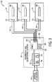
- FIG. 3 is a schematic illustration of the present hazardous gas monitoring system 34 (e.g., aspirated driven system) coupled to a plurality of enclosures 14.
- the hazardous gas monitoring system 34 includes a plurality of sensing lines 64 coupled to the enclosures 14.
- the number of enclosures 14 coupled to the hazardous gas monitoring system 34 may vary (e.g., 1, 2, 3, 4, or more).
- Each enclosure 14 includes a turbomachine 68 (e.g., gas turbine 12, generator, or other turbomachine).
- the turbomachines 68 may form a portion of a power plant 69.
- One or more sensing lines 64 may be coupled to each enclosure 14. As depicted, at least two sensing lines 64 are coupled to each enclosure 14.
- Each sensing line 64 extends into the respective enclosure 14 to a sensing point 70 where an air sample is aspirated into the sensing line 64.
- the panel 66 may be disposed within a cabinet 80.
- the cabinet 80 may include a heater 82 to keep the sensing lines 64 coupled to the panel 66 above freezing (0 degrees Celsius) to keep any moisture within the sensing lines 64 from freezing.
- the cabinet 80 may also include a thermostat 84 to provide an indication of the temperature within the cabinet 80.
- the hazardous gas monitoring system 34 includes a controller 72 communicatively coupled to a flow and gas monitoring system 96 ( FIG. 4 ) of each sensing line 64.
- the controller 72 is communicatively coupled (e.g., data transfer, receiving and giving instructions) with a service platform 74 (e.g., cloud computing service, distributed control system) and/or various components and systems of the turbomachines 68 via wired or wireless network or communication system.
- the controller 72 may be part of the service platform 74.
- the controller 72 has a processor 76 and a memory 78 (e.g., a non-transitory computer-readable medium/memory circuitry) communicatively coupled to the processor 76, storing one or more sets of instructions (e.g., processor-executable instructions) implemented to perform operations related to the hazardous gas monitoring system 34 and/or turbomachines 68.
- a processor 76 and a memory 78 (e.g., a non-transitory computer-readable medium/memory circuitry) communicatively coupled to the processor 76, storing one or more sets of instructions (e.g., processor-executable instructions) implemented to perform operations related to the hazardous gas monitoring system 34 and/or turbomachines 68.
- operations may relate to monitoring the flow of the sample within each sensing line 64, regulating a temperature within the cabinet 80 via the heater 82, regulating a temperature of heat traces on portions of the sensing lines 64 outside of the panel 66 (discussed further herein), monitoring the presence of hazardous gases within the air samples, and/or providing an action (e.g., safety action such as shutting down an individual turbomachine 68 or providing a user perceptible warning) in response to detecting hazardous gas at an actionable concentration or volume.
- an action e.g., safety action such as shutting down an individual turbomachine 68 or providing a user perceptible warning
- the memory 78 may include volatile memory, such as random-access memory (RAM), and/or non-volatile memory, such as read-only memory (ROM), optical drives, hard disc drives, or solid-state drives.
- the processor 76 may include one or more application specific integrated circuits (ASICs), one or more field programmable gate arrays (FPGAs), one or more general purpose processors, or any combination thereof.
- ASICs application specific integrated circuits
- FPGAs field programmable gate arrays
- general purpose processors or any combination thereof.
- processor is not limited to just those integrated circuits referred to in the art as processors, but broadly refers to computers, processors, microcontrollers, microcomputers, programmable logic controllers, application specific integrated circuits, and other programmable circuits.
- the memory 78 may store various limits or ranges related to parameters (e.g., flow rate, flow speed, flow volume, etc.) of a flow of the samples within the sampling lines 64, temperature within the cabinet 80 or on the sampling lines outside the cabinet, and/or hazardous gas concentrations (and associated upper and lower level explosive limits).
- the memory 78 may store information inputted by operators or users (e.g., via the controller 72 and/or via the service platform 74). Information may be collected via the flow and gas monitoring system 96 ( FIG. 4 ) of each sensing line 64, thermostat 84, or other equipment (e.g., temperature sensor providing ambient temperature about the monitoring system 34).
- FIG. 4 is a schematic illustration of an embodiment of the panel 66 (e.g., hazardous gas monitoring panel) of a hazardous gas monitoring system 34.
- the panel 66 includes a panel wall 86.
- the panel wall 86 includes a plurality of sensing lines 64.
- the panel wall 86 includes two sensing lines 64 (e.g., sensing lines 88, 90).
- the number of sensing lines 64 associated with the panel 66 may vary (e.g., 1, 2, 3, 4, or more).
- the sensing lines 88, 90 are associated with sensing points 1 and 2 from which a respective air sample is aspirated.
- Sensing points 1 and 2 may disposed in the same enclosure (e.g., housing a turbomachine) or different enclosures. In certain embodiments, each enclosure may include two or more sensing points (and associated sensing lines 64) coupled to the panel 66.
- Each sensing line 64 includes a water separator 92, a coalescing filter or coalescer 94, and a flow and gas monitoring system 96 disposed downstream of the coalescer 94.
- the water separator 92 removes condensed moisture from the sensing line 64.
- the coalescer 94 further separates moisture from the sensing line 64.
- the flow and gas monitoring system 96 includes a flow indicator 98, a flow monitor 100, and one or more gas sensors 102.
- the flow and gas monitoring system 96 may be communicatively coupled to a controller (e.g., controller 72 of FIG. 3 ).
- the flow indicator 98 e.g., ball style sight flow indicator
- the flow monitor 100 includes one or more sensors (e.g., flow meters, ultrasonic flow meters, etc.) and circuitry (e.g., processing and memory circuitry) to detect a parameter (e.g., flow rate, flow volume, etc.) of the sample flow in a respective sensing line and to determine if the parameter is at an undesired level (e.g., outside a range, below a certain limit, etc.).
- the one or more gas sensors 102 are utilized to detect a presence of a hazardous gas in the sample flow.
- the one or more gas sensors 102 may include microstructured gas sensors, flow infrared point sensors, infrared cameras, and/or ultrasonic sensors.
- the one or more gas sensors 102 may be able to detect one or more specific gases (e.g., natural gas, hydrogen, etc.). As depicted in FIG. 4 , the flow monitor 100 is disposed downstream of the flow indicator 98 and the one or more gas sensors 102 are disposed downstream of both the flow indicator 98 and the flow monitor 100. In certain embodiments, the flow indicator 98, the flow monitor 100, and the one or more gas sensors 102 may be disposed in a different order.
- one or more specific gases e.g., natural gas, hydrogen, etc.
- each sensing line 64 splits into a flow and gas monitoring line 104 and a drainage line 106.
- the air sample to be monitored flows along the flow and gas monitoring line 104 through the flow and gas monitoring system 96, and any moisture separated from the air sample flows along the drainage line 106.
- An orifice 108 e.g., flow limiting orifice
- An orifice 110 is also disposed along the drainage line 106.
- the orifices 108, 110 are sized for optimal flow split and/or pressure drop among the various lines.
- the flow and gas monitoring line 104 and the drainage line 106 join again downstream of the orifices 108, 110. Downstream of the merging of the respective flow and gas monitoring lines 104 and drainage lines 106 of the sensing lines 88, 90, the sensing lines 88, 90 merge for the discharge of the air samples from an ejector 118 into the atmosphere.
- Orifices 114, 116 e.g., flow limiting orifices
- the orifices 114, 116 are sized for optimal flow split and/or pressure drop between the various lines.
- the common drainage line 112 discharges the moisture from the air samples from a separate ejector 120.
- instrument air is provided from an instrument air supply 122, via air line 124, to each of the ejectors 118, 120. Discharging the air samples into the atmosphere (instead of returning them via an exhaust line to the enclosure) keeps back pressure from forming and hindering flow within the system.
- At least one sensing line 64 may be inactive while another sensing line 64 (e.g., sensing line 90) is still active to enable the turbomachine (e.g., gas turbine or generator) to keep operating. This may enable a sensor change out or maintenance for the sensing line 88, while the other sensing line 90 monitors for the presence of hazardous gas in the enclosure.
- the turbomachine e.g., gas turbine or generator
- FIG. 5 is a schematic illustration of an embodiment of the sensing line 64 with heat traces 126.
- the heat traces 126 are disposed on a conduit wall 128 of the sensing line 64.
- the heat traces 126 may maintain or raise the temperature of the conduit wall 128 to keep the temperature of the sensing line 64 above freezing (0 degrees Celsius) to keep moisture from freezing within the sensing line 64.
- each heat trace 126 may take the form of an electrical heating element run in physical contact along the length of a conduit wall 128.
- the heat traces 126 may be controlled by a controller (e.g., controller 72 in FIG. 3 ).
- a hazardous gas monitoring system that includes a panel coupled to a plurality of sensing lines, which in turn are coupled to one or more enclosures (e.g., enclosures housing turbomachines).
- the panel includes features to avoid moisture accumulation and freezing of moisture within the sensing lines. By keeping moisture from building up or freezing from occurring in the monitoring system, the reliability of the monitoring system may be increased, while avoiding costly and unnecessary shutdowns or trips of the power generation system.
Landscapes
- Chemical & Material Sciences (AREA)
- Engineering & Computer Science (AREA)
- Health & Medical Sciences (AREA)
- Life Sciences & Earth Sciences (AREA)
- Combustion & Propulsion (AREA)
- Physics & Mathematics (AREA)
- General Physics & Mathematics (AREA)
- Immunology (AREA)
- Pathology (AREA)
- Analytical Chemistry (AREA)
- Biochemistry (AREA)
- General Health & Medical Sciences (AREA)
- Medicinal Chemistry (AREA)
- Food Science & Technology (AREA)
- Mechanical Engineering (AREA)
- General Engineering & Computer Science (AREA)
- Spectroscopy & Molecular Physics (AREA)
- Biomedical Technology (AREA)
- Molecular Biology (AREA)
- Chemical Kinetics & Catalysis (AREA)
- General Chemical & Material Sciences (AREA)
- Oil, Petroleum & Natural Gas (AREA)
- Organic Chemistry (AREA)
- Sampling And Sample Adjustment (AREA)
- Testing Of Devices, Machine Parts, Or Other Structures Thereof (AREA)
Abstract
Description
- The present disclosure relates generally to turbomachines. In particular, the present disclosure relates to systems for hazardous gas monitoring in an enclosure of a turbomachine.
- Gas turbines and/or generators (e.g., hydrogen-cooled generators) are used to generate power for various applications. To protect the turbine and/or generator from the surrounding environment and vise versa, the turbine and/or generator may be housed or enclosed in an enclosure with appropriate inlets, exhaust outlets, and/or ventilations, etc. For example, a gas turbine and/or generator may be housed inside an enclosure, which may facilitate reducing noise during turbine operation and which may contain environmental hazards such as combustible gases (e.g., fuel gas or hydrogen) from leaking to the surrounding environment. A monitoring system may be fluidly coupled to an enclosure to sample the air within the enclosure to detect the presence of hazardous gas. Unfortunately, under certain conditions, these monitoring systems may trip the power generation units (e.g., due to moisture or ice in the sensing lines), resulting in unnecessary costly shutdowns. Due to this issue, certain operators may inactivate monitoring systems and forego monitoring for hazardous gas within the enclosure.
- Certain embodiments commensurate in scope with the originally claimed subject matter are summarized below. These embodiments are not intended to limit the scope of the claimed embodiments, but rather these embodiments are intended only to provide a brief summary of possible forms of the subject matter. Indeed, the presently claimed embodiments may encompass a variety of forms that may be similar to or different from the embodiments set forth below.
- In a first embodiment, a hazardous gas monitoring system is provided. The hazardous gas monitoring system includes a panel including multiple sensing lines. Each sensing line is configured to receive and monitor an air sample. Each sensing line includes a water separator to remove condensed moisture, a coalescing filter disposed downstream of the water separator, and a flow and gas monitoring system disposed downstream of the coalescing filter.
- In a second embodiment, a hazardous gas monitoring system is provided. The hazardous gas monitoring system includes a panel including multiple sensing lines. Each sensing line is configured to receive and monitor an air sample from an enclosure housing a turbomachine. Each sensing line includes a water separator to remove condensed moisture, and the multiple sensing lines discharge respective air samples to the atmosphere.
- In a third embodiment, a hazardous gas monitoring system is provided. The hazardous gas monitoring system includes a panel including a first sensing line and a second sensing line. The first and second sensing lines are each configured to receive and monitor an air sample from an enclosure housing a turbomachine. The first and second sensing lines each include a water separator to remove condensed moisture. Respective water separators of the first and second sensing lines are coupled to a common drainage line, and a respective orifice is disposed between each respective water separator and the common drainage line.
- These and other features, aspects, and advantages of the presently disclosed techniques will become better understood when the following detailed description is read with reference to the accompanying drawings in which like characters represent like parts throughout the drawings, wherein:
-
FIG. 1 is a partial schematic illustration of a turbine system having a gas turbine in a gas turbine enclosure utilizing a hazardous gas monitoring system for monitoring for gas leakage, in accordance with an embodiment; -
FIG. 2 is a schematic illustration of the turbine system utilizing the hazardous gas monitoring system for monitoring for gas leakage, in accordance with an embodiment of the present disclosure; -
FIG. 3 is a schematic illustration of an embodiment of a hazardous gas monitoring system coupled to a plurality of enclosures; -
FIG. 4 is a schematic illustration of an embodiment of a panel (e.g., a hazardous gas detection panel) of a hazardous gas monitoring system; and -
FIG. 5 is a schematic illustration of an embodiment of a sensing line with heat traces, which may be used in embodiments of the present hazardous gas monitoring system. - One or more specific embodiments of the presently disclosed embodiments will be described below. In an effort to provide a concise description of these embodiments, all features of an actual implementation may not be described in the specification. It should be appreciated that in the development of any such actual implementation, as in any engineering or design project, numerous implementation-specific decisions must be made to achieve the developers' specific goals, such as compliance with system-related and business-related constraints, which may vary from one implementation to another. Moreover, it should be appreciated that such a development effort might be complex and time consuming, but would nevertheless be a routine undertaking of design, fabrication, and manufacture for those of ordinary skill having the benefit of this disclosure.
- When introducing elements of various embodiments of the presently disclosed embodiments, the articles "a," "an," "the," and "said" are intended to mean that there are one or more of the elements. The terms "comprising," "including," and "having" are intended to be inclusive and mean that there may be additional elements other than the listed elements.
- As described below, a hazardous gas monitoring system is intended for monitoring presence of hazardous gases (e.g., combustible gases, such as a fuel gas (e.g., natural gas) in a gas turbine enclosure or hydrogen in a generator enclosure) inside an equipment area (e.g., an enclosure) for a turbomachine (e.g., a gas turbine, a generator, etc.). In particular, the hazardous gas monitoring system includes a panel with freezing and moisture buildup protection. The panel includes multiple sensing lines or sensing conduits that provide air samples from sensing points (where sample probes are located) in one or more enclosures. Each sensing line includes a flow monitor configured to proactively monitor and determine if the sample flow drops to an unacceptable level.
- Each sensing line also includes a water separator to remove condensed moisture from the sensing lines to reduce the likelihood of freezing. To keep any remaining condensed water from freezing within the sensing lines, the panel may be disposed within a cabinet with a heater and a thermostat. In addition, the portions of the sensing lines disposed outside of the panel may have heat traces on them to keep water from freezing within the sensing lines. By keeping moisture from building up or freezing from occurring in the monitoring system, the reliability of the monitoring system may be increased, while avoiding costly and unnecessary shutdowns or trips of the power generation system.
- In certain embodiments, at least one sensing line may be inactive (e.g., for a sensor change out or maintenance) while another sensing line is still active to enable the turbomachine to keep operating. Further, in some embodiments, the sensing lines may discharge the air samples after monitoring to the atmosphere (instead of returning them to the enclosure via an exhaust line) to avoid back pressure that may impact the monitoring system.
-
FIG. 1 is a partial schematic of an embodiment of aturbine system 10, enclosed or housed by a turbine enclosure 14 (e.g., gas turbine enclosure). Theturbine system 10 may be a stationary or mobile gas turbine power generation unit. For example, theturbine system 10 may be a stationary unit disposed in a power plant, such as integrated gasification combined cycle (IGCC) power plant. For example, theturbine system 10 may be a mobile unit carried by a trailer. Theturbine system 10 includes a gas turbine orgas turbine engine 12, the enclosure 14 (e.g., gas turbine enclosure) that houses thegas turbine 12, and a load 16 (e.g., generator, electrical generator) driven by thegas turbine 12. Theturbine system 10 also includes a combustionair intake system 18 upstream from thegas turbine 12 and a ventilationair intake system 20. Thegas turbine enclosure 14 may define a first intake port 22 (e.g., first air intake port or turbine air intake), a second intake port 24 (e.g., second air intake port or enclosure ventilation intake), anair exit port 26, and anexhaust exit port 27. - The
first intake port 22 is coupled to the combustionair intake system 18 upstream from thegas turbine 12. The combustionair intake system 18 may include one or more filters to filter air provided to thegas turbine 12. Thefirst intake port 22 directs air into thegas turbine 12. For example, thefirst intake port 22 may direct air into a compressor of thegas turbine 12. For example, thegas turbine 12 may compress the air fromport 22, mix the air with fuel in one or combustors, and combust the air-fuel mixture to drive one or more turbines. - The
second intake port 24 is coupled to the ventilationair intake system 20. The ventilationair intake system 20 may include one or more filters to filter air provided to theenclosure 14 of thegas turbine 12. The ventilationair intake system 20 may provide air into theenclosure 14 via one ormore fans 30. Thesecond intake port 24 directs air into theenclosure 14 surrounding thegas turbine 12 to ventilate the enclosure. - The
exhaust exit port 27 is coupled to a combustion exhaust stack orcombustion exhaust duct 28 for venting exhaust gases from thegas turbine 12. Theair exit port 26 is coupled to aduct 29 for discharging the ventilation air. Thegas turbine 12 includes ashaft 32 that extends through theenclosure 14 and couples to theload 16. As described in greater detail below, a hazardousgas monitoring system 34 may be utilized to monitor for the presence of hazardous gases (e.g., combustible gases) within theenclosure 14. The hazardousgas monitoring system 34 is an aspirated system that samples air from theenclosure 14 and monitors gas concentration to determine an appropriate safety action if hazardous gas is present. As described in greater detail below, the hazardousgas monitoring system 34 is configured to keep moisture from accumulating or freezing in themonitoring system 34. -
FIG. 2 is a schematic of an embodiment of theturbine system 10 utilizing the present hazardousgas monitoring system 34 for monitoring for gas leakage. The turbine system (e.g., gas turbine system, dual-fuel turbine system) 10 may use liquid or gas fuel, such as natural gas and/or a hydrogen rich synthetic gas, to drive theturbine system 10. As depicted, in eachcombustor 58 of a plurality ofcombustors 58, fuel nozzles 50 (e.g., multi-tube fuel nozzles) intake afuel supply 52 from aliquid fuel system 54 or agaseous fuel system 56 and mix the fuel with an oxidant (such as air, oxygen, oxygen-enriched air, oxygen reduced air, or any combination thereof), which may be supplied by acompressor 62. Although the following discussion refers to the oxidant as the air, any suitable oxidant may be used with the disclosed embodiments. - Once the fuel and air have been mixed, the
fuel nozzles 50 distribute the fuel-air mixture in a suitable ratio for optimal combustion, emissions, fuel consumption, and power output. Theturbine system 10 may include one ormore fuel nozzles 50 located inside each of the plurality ofcombustors 58. The fuel-air mixture combusts in a chamber within each of the plurality ofcombustors 58, thereby creating hot pressurized exhaust gases. - The plurality of
combustors 58 direct the exhaust gases through a turbine section (or "expansion turbine") 40 of thegas turbine 12 toward an exhaust outlet 60 (e.g., directed to the exit port 27). As the exhaust gases pass through theturbine section 40, the gases force turbine blades to rotate thedrive shaft 32 along an axis of theturbine system 10. As illustrated, theshaft 32 may be connected to various components of theturbine system 10, including thecompressor 62. Thecompressor 62 also includes blades coupled to theshaft 32. As theshaft 32 rotates, the blades within thecompressor 62 also rotate, thereby compressing air from the first (air)intake port 22 through thecompressor 62 and into thefuel nozzles 50 and/or the plurality ofcombustors 58. The fuel nozzles 50 may contain fuel plenums or may connect with an end cover having fuel plenums, which may improve fuel distribution within thenozzles 50 before the fuel-air mixture is discharged into thecombustor 58. - The
shaft 32 may also be connected to theload 16, which may be a vehicle or a stationary load, such as an electrical generator in a power plant or a propeller on an aircraft, for example. Theload 16 may include any suitable device capable of being powered by the rotational output of theturbine system 10. - As described in greater detail below, the hazardous
gas monitoring system 34 may be utilized to sample air within theenclosure 14 for detecting, monitoring, and assessing the presence and volume of hazardous gases, which may be present in the event of a fuel leak. Although the hazardousgas monitoring system 34 has been discussed relative to agas turbine system 10, themonitoring system 34 may be utilized with other turbomachines, such as hydrogen-cooled generators. In addition, the hazardousgas monitoring system 34 may be utilized to monitor any other type of equipment area or enclosure where it is desirable to monitor for the presence of hazardous gases. -
FIG. 3 is a schematic illustration of the present hazardous gas monitoring system 34 (e.g., aspirated driven system) coupled to a plurality ofenclosures 14. The hazardousgas monitoring system 34 includes a plurality ofsensing lines 64 coupled to theenclosures 14. The number ofenclosures 14 coupled to the hazardous gas monitoring system 34 (in particular, apanel 66 of the system 34) may vary (e.g., 1, 2, 3, 4, or more). Eachenclosure 14 includes a turbomachine 68 (e.g.,gas turbine 12, generator, or other turbomachine). Theturbomachines 68 may form a portion of apower plant 69. One ormore sensing lines 64 may be coupled to eachenclosure 14. As depicted, at least two sensinglines 64 are coupled to eachenclosure 14. Eachsensing line 64 extends into therespective enclosure 14 to asensing point 70 where an air sample is aspirated into thesensing line 64. In certain embodiments, thepanel 66 may be disposed within acabinet 80. Thecabinet 80 may include aheater 82 to keep thesensing lines 64 coupled to thepanel 66 above freezing (0 degrees Celsius) to keep any moisture within thesensing lines 64 from freezing. Thecabinet 80 may also include athermostat 84 to provide an indication of the temperature within thecabinet 80. - The hazardous
gas monitoring system 34 includes acontroller 72 communicatively coupled to a flow and gas monitoring system 96 (FIG. 4 ) of eachsensing line 64. In certain embodiments, thecontroller 72 is communicatively coupled (e.g., data transfer, receiving and giving instructions) with a service platform 74 (e.g., cloud computing service, distributed control system) and/or various components and systems of theturbomachines 68 via wired or wireless network or communication system. In some embodiments, thecontroller 72 may be part of theservice platform 74. Thecontroller 72 has aprocessor 76 and a memory 78 (e.g., a non-transitory computer-readable medium/memory circuitry) communicatively coupled to theprocessor 76, storing one or more sets of instructions (e.g., processor-executable instructions) implemented to perform operations related to the hazardousgas monitoring system 34 and/orturbomachines 68. - For example, operations may relate to monitoring the flow of the sample within each sensing
line 64, regulating a temperature within thecabinet 80 via theheater 82, regulating a temperature of heat traces on portions of thesensing lines 64 outside of the panel 66 (discussed further herein), monitoring the presence of hazardous gases within the air samples, and/or providing an action (e.g., safety action such as shutting down anindividual turbomachine 68 or providing a user perceptible warning) in response to detecting hazardous gas at an actionable concentration or volume. - More specifically, the
memory 78 may include volatile memory, such as random-access memory (RAM), and/or non-volatile memory, such as read-only memory (ROM), optical drives, hard disc drives, or solid-state drives. Additionally, theprocessor 76 may include one or more application specific integrated circuits (ASICs), one or more field programmable gate arrays (FPGAs), one or more general purpose processors, or any combination thereof. Furthermore, the term "processor" is not limited to just those integrated circuits referred to in the art as processors, but broadly refers to computers, processors, microcontrollers, microcomputers, programmable logic controllers, application specific integrated circuits, and other programmable circuits. - For example, the
memory 78 may store various limits or ranges related to parameters (e.g., flow rate, flow speed, flow volume, etc.) of a flow of the samples within thesampling lines 64, temperature within thecabinet 80 or on the sampling lines outside the cabinet, and/or hazardous gas concentrations (and associated upper and lower level explosive limits). For example, thememory 78 may store information inputted by operators or users (e.g., via thecontroller 72 and/or via the service platform 74). Information may be collected via the flow and gas monitoring system 96 (FIG. 4 ) of eachsensing line 64,thermostat 84, or other equipment (e.g., temperature sensor providing ambient temperature about the monitoring system 34). -
FIG. 4 is a schematic illustration of an embodiment of the panel 66 (e.g., hazardous gas monitoring panel) of a hazardousgas monitoring system 34. Thepanel 66 includes apanel wall 86. Thepanel wall 86 includes a plurality of sensing lines 64. As depicted, thepanel wall 86 includes two sensing lines 64 (e.g., sensinglines 88, 90). As noted above, the number ofsensing lines 64 associated with thepanel 66 may vary (e.g., 1, 2, 3, 4, or more). As depicted, thesensing lines sensing points panel 66. - Each
sensing line 64 includes awater separator 92, a coalescing filter orcoalescer 94, and a flow andgas monitoring system 96 disposed downstream of thecoalescer 94. Thewater separator 92 removes condensed moisture from thesensing line 64. Thecoalescer 94 further separates moisture from thesensing line 64. The flow andgas monitoring system 96 includes aflow indicator 98, aflow monitor 100, and one ormore gas sensors 102. The flow andgas monitoring system 96 may be communicatively coupled to a controller (e.g.,controller 72 ofFIG. 3 ). The flow indicator 98 (e.g., ball style sight flow indicator) provides a visual indication of sample flow in thesensing line 64. The flow monitor 100 includes one or more sensors (e.g., flow meters, ultrasonic flow meters, etc.) and circuitry (e.g., processing and memory circuitry) to detect a parameter (e.g., flow rate, flow volume, etc.) of the sample flow in a respective sensing line and to determine if the parameter is at an undesired level (e.g., outside a range, below a certain limit, etc.). The one ormore gas sensors 102 are utilized to detect a presence of a hazardous gas in the sample flow. The one ormore gas sensors 102 may include microstructured gas sensors, flow infrared point sensors, infrared cameras, and/or ultrasonic sensors. The one ormore gas sensors 102 may be able to detect one or more specific gases (e.g., natural gas, hydrogen, etc.). As depicted inFIG. 4 , the flow monitor 100 is disposed downstream of theflow indicator 98 and the one ormore gas sensors 102 are disposed downstream of both theflow indicator 98 and theflow monitor 100. In certain embodiments, theflow indicator 98, the flow monitor 100, and the one ormore gas sensors 102 may be disposed in a different order. - As depicted in
FIG. 4 , at thecoalescer 94, each sensingline 64 splits into a flow andgas monitoring line 104 and adrainage line 106. The air sample to be monitored flows along the flow andgas monitoring line 104 through the flow andgas monitoring system 96, and any moisture separated from the air sample flows along thedrainage line 106. An orifice 108 (e.g., flow limiting orifice) is disposed along the flow andgas monitoring line 104 downstream of the flow andgas monitoring system 96. An orifice 110 (e.g., flow limiting orifice) is also disposed along thedrainage line 106. Theorifices gas monitoring line 104 and thedrainage line 106 join again downstream of theorifices gas monitoring lines 104 anddrainage lines 106 of thesensing lines sensing lines ejector 118 into the atmosphere. - Moisture separated from the
respective water separators 92 of thesensing lines common drainage line 112.Orifices 114, 116 (e.g., flow limiting orifices) are disposed between therespective water separators 92 and thecommon drainage line 112. Theorifices common drainage line 112 discharges the moisture from the air samples from aseparate ejector 120. - To facilitate discharge (e.g., via aspiration) of the sample to the atmosphere from
ejectors instrument air supply 122, viaair line 124, to each of theejectors - In certain embodiments, at least one sensing line 64 (e.g., sensing line 88) may be inactive while another sensing line 64 (e.g., sensing line 90) is still active to enable the turbomachine (e.g., gas turbine or generator) to keep operating. This may enable a sensor change out or maintenance for the
sensing line 88, while theother sensing line 90 monitors for the presence of hazardous gas in the enclosure. -
FIG. 5 is a schematic illustration of an embodiment of thesensing line 64 with heat traces 126. The heat traces 126 are disposed on aconduit wall 128 of thesensing line 64. The heat traces 126 may maintain or raise the temperature of theconduit wall 128 to keep the temperature of thesensing line 64 above freezing (0 degrees Celsius) to keep moisture from freezing within thesensing line 64. In certain embodiments, eachheat trace 126 may take the form of an electrical heating element run in physical contact along the length of aconduit wall 128. In certain embodiments, the heat traces 126 may be controlled by a controller (e.g.,controller 72 inFIG. 3 ). - Technical effects of the disclosed embodiments include providing a hazardous gas monitoring system that includes a panel coupled to a plurality of sensing lines, which in turn are coupled to one or more enclosures (e.g., enclosures housing turbomachines). The panel includes features to avoid moisture accumulation and freezing of moisture within the sensing lines. By keeping moisture from building up or freezing from occurring in the monitoring system, the reliability of the monitoring system may be increased, while avoiding costly and unnecessary shutdowns or trips of the power generation system.
- This written description uses examples to describe the present embodiments, including the best mode, and also to enable any person skilled in the art to practice the presently disclosed embodiments, including making and using any devices or systems and performing any incorporated methods. The patentable scope of the presently disclosed embodiments is defined by the claims and may include other examples that occur to those skilled in the art. Such other examples are intended to be within the scope of the claims if they have structural elements that do not differ from the literal language of the claims, or if they include equivalent structural elements with insubstantial differences from the literal language of the claims.
Claims (10)
- A hazardous gas monitoring system (34), comprising:
a panel (66) comprising a plurality of sensing lines (64), wherein each sensing line (64) is configured to receive and monitor an air sample and each sensing line (64) of the plurality of sensing lines (64) comprises:a water separator (92) to remove condensed moisture from the air sample;a coalescing filter (94) disposed downstream of the water separator (92); anda flow and gas monitoring system (96) disposed downstream of the coalescing filter (94). - The hazardous gas monitoring system (34) of claim 1, wherein each sensing line (64) of the plurality of sensing lines (64) splits into a flow and gas monitoring line (104) and a drainage line (106).
- The hazardous gas monitoring system (34) of claim 2, wherein the split between the flow and gas monitoring line (104) and the drainage line (106) occurs at the coalescing filter (94).
- The hazardous gas monitoring system (34) of claim 2, wherein, in each sensing line (64) of the plurality of sensing lines (64), a first orifice (108) is disposed along the flow and gas monitoring line (104) downstream of the flow and gas monitoring system (96) to limit sample flow, and a second orifice (110) is disposed along the drainage line (106) to limit drainage flow.
- The hazardous gas monitoring system (34) of claim 1, wherein respective water separators (92) of at least two sensing lines (64) of the plurality of sensing lines (64) are coupled to a common drainage line (112).
- The hazardous gas monitoring system (34) of claim 5, wherein, for the at least two sensing lines (64) of the plurality of sensing lines (64), a respective orifice (114, 116) is disposed between the respective water separator (92) and the common drainage line (112).
- The hazardous gas monitoring system (34) of claim 5, wherein the common drainage line (112) is coupled to a first ejector (120) to discharge drainage flow to atmosphere.
- The hazardous gas monitoring system (34) of claim 7, wherein the at least two sensing lines (64) of the plurality of sensing lines (64) are coupled to a second ejector (118) to discharge both sample flow and drainage flow to the atmosphere.
- The hazardous gas monitoring system (34) of claim 8, wherein an instrument air supply (122) is fluidly coupled to both the first and second ejectors (118, 120) to facilitate discharge.
- The hazardous gas monitoring system (34) of claim 1, wherein the hazardous gas monitoring system (34) is configured to utilize a first sensing line (64) of the plurality of sensing lines (64) while a second sensing line (64) of the plurality of sensing lines (64) is deactivated or disconnected.
Applications Claiming Priority (1)
| Application Number | Priority Date | Filing Date | Title |
|---|---|---|---|
| US16/892,469 US11873764B2 (en) | 2020-06-04 | 2020-06-04 | Hazardous gas monitoring system |
Publications (1)
| Publication Number | Publication Date |
|---|---|
| EP3919900A1 true EP3919900A1 (en) | 2021-12-08 |
Family
ID=76305707
Family Applications (1)
| Application Number | Title | Priority Date | Filing Date |
|---|---|---|---|
| EP21174193.9A Pending EP3919900A1 (en) | 2020-06-04 | 2021-05-17 | Hazardous gas monitoring system |
Country Status (4)
| Country | Link |
|---|---|
| US (1) | US11873764B2 (en) |
| EP (1) | EP3919900A1 (en) |
| JP (1) | JP7770782B2 (en) |
| CN (1) | CN113759077A (en) |
Families Citing this family (2)
| Publication number | Priority date | Publication date | Assignee | Title |
|---|---|---|---|---|
| KR20250124318A (en) * | 2022-12-23 | 2025-08-19 | 지이 버노바 테크놀로지 게엠베하 | gas detection system |
| US12637229B2 (en) * | 2023-09-22 | 2026-05-26 | General Electric Company | Methods and apparatus for leak detection and mitigation for hydrogen fueled aircraft |
Citations (1)
| Publication number | Priority date | Publication date | Assignee | Title |
|---|---|---|---|---|
| US20040099045A1 (en) * | 2002-11-26 | 2004-05-27 | Proton Energy Systems | Combustible gas detection systems and method thereof |
Family Cites Families (19)
| Publication number | Priority date | Publication date | Assignee | Title |
|---|---|---|---|---|
| GB190112923A (en) * | 1901-06-25 | 1902-05-08 | Alfred Julius Boult | Improvements in or relating to Water Separators for Steam Conduits and the like. |
| US5205177A (en) * | 1991-01-23 | 1993-04-27 | Research-Cottrell, Inc. | Method and apparatus for gas monitoring |
| AU4915397A (en) * | 1996-10-18 | 1998-05-15 | Westinghouse Savannah River Company | Programmable atmospheric sampling systems and methods |
| US5918616A (en) * | 1996-11-15 | 1999-07-06 | Sanfilippo; James J. | Apparatus and method of controlling gas flow |
| US5933574A (en) * | 1998-02-09 | 1999-08-03 | Avansino; Gary L. | Heated fluid conduit |
| US7111493B2 (en) * | 2002-11-26 | 2006-09-26 | Proton Energy Systems, Inc. | Combustible gas detection system |
| US7850838B2 (en) * | 2006-08-01 | 2010-12-14 | Proton Energy Systems, Inc. | Cold weather hydrogen generation system and method of operation |
| US7449661B1 (en) * | 2006-11-03 | 2008-11-11 | Bench Steven D | In-pipe heat trace system |
| EP1925935A1 (en) * | 2006-11-23 | 2008-05-28 | Varian B.V. | Gas detection system and method |
| JP5226435B2 (en) * | 2008-08-29 | 2013-07-03 | 株式会社堀場製作所 | Exhaust gas measuring device and exhaust gas measuring method |
| US20110313670A1 (en) * | 2010-06-17 | 2011-12-22 | Pason Systems Corp. | Method and apparatus for speciating hydrocarbons |
| JP5885015B2 (en) * | 2011-09-06 | 2016-03-15 | セイコーエプソン株式会社 | Gas sensor |
| JP2013160525A (en) * | 2012-02-01 | 2013-08-19 | Mitsubishi Heavy Ind Ltd | Nitrogen oxide measuring instrument |
| US20150226129A1 (en) * | 2014-02-10 | 2015-08-13 | General Electric Company | Method for Detecting Hazardous Gas Concentrations within a Gas Turbine Enclosure |
| US9366192B2 (en) | 2014-02-10 | 2016-06-14 | General Electric Company | Hazardous gas detection system for a gas turbine enclosure |
| US11209391B2 (en) * | 2016-09-08 | 2021-12-28 | Atonarp Inc. | System having a pre-separation unit |
| AU2017387061B2 (en) * | 2016-12-27 | 2019-08-22 | Panametrics Llc | Portable moisture analyzer for natural gas |
| CN108872124B (en) * | 2017-05-12 | 2020-12-08 | 中国石油化工股份有限公司 | Online carbon monoxide analyzer and heating furnace combustion control system |
| CN210269029U (en) * | 2019-08-19 | 2020-04-07 | 上海迪勤传感技术有限公司 | Dangerous gas leakage real-time monitoring system |
-
2020
- 2020-06-04 US US16/892,469 patent/US11873764B2/en active Active
-
2021
- 2021-05-07 CN CN202110494116.5A patent/CN113759077A/en active Pending
- 2021-05-10 JP JP2021080069A patent/JP7770782B2/en active Active
- 2021-05-17 EP EP21174193.9A patent/EP3919900A1/en active Pending
Patent Citations (1)
| Publication number | Priority date | Publication date | Assignee | Title |
|---|---|---|---|---|
| US20040099045A1 (en) * | 2002-11-26 | 2004-05-27 | Proton Energy Systems | Combustible gas detection systems and method thereof |
Also Published As
| Publication number | Publication date |
|---|---|
| US20210381437A1 (en) | 2021-12-09 |
| CN113759077A (en) | 2021-12-07 |
| JP2021189172A (en) | 2021-12-13 |
| JP7770782B2 (en) | 2025-11-17 |
| US11873764B2 (en) | 2024-01-16 |
Similar Documents
| Publication | Publication Date | Title |
|---|---|---|
| EP3105582B1 (en) | Gas turbine enclosure with a hazardous gas detection system | |
| US10196928B2 (en) | Method and system for piping failure detection in a gas turbine bleeding air system | |
| US20260077867A1 (en) | Ice Detection and Precautionary System Shut-Down Event Reduction Systems and Related Methods | |
| CN115108030A (en) | Hydrogen fuel leakage detection system | |
| US20180080846A1 (en) | Mobile hazgas/fire detection system | |
| US11873764B2 (en) | Hazardous gas monitoring system | |
| CN106979073B (en) | Systems that generate steam and provide cooled combustion gases | |
| CN206429308U (en) | Extracted via turbine and compressor extracts the system for producing steam | |
| CN115756035B (en) | Aircraft engine high-altitude transition state full-environment simulation test platform and control method | |
| CN205064100U (en) | Combined cycle power plant | |
| US20150226129A1 (en) | Method for Detecting Hazardous Gas Concentrations within a Gas Turbine Enclosure | |
| CN107035523A (en) | Extracted via turbine and compressor extracts the system for producing steam | |
| CN106979074A (en) | Extracted via turbine and compressor extracts the system for producing steam | |
| EP0616118A1 (en) | Gas turbine surge/flameout protection against water ingestion | |
| CN116395142A (en) | Safety management of propulsion systems with fuel cells | |
| CN103411785A (en) | Method for measuring performance of centrifugal ventilator | |
| CN113847143B (en) | Systems and methods for detecting excess flow in fluid systems | |
| US20230016408A1 (en) | Detecting a fuel leak in an engine fuel system | |
| Prahst et al. | Experimental results of the first two stages of an advanced transonic core compressor under isolated and multi-stage conditions | |
| CN115307820A (en) | System and method for efficiently detecting hazardous gas leaks within a gas turbine compartment | |
| US8720201B2 (en) | Method of monitoring an electronic engine control (EEC) to detect a loss of fuel screen open area | |
| US9657639B2 (en) | Ventilation system and method for monitoring air flow in a ventilation system for a turbomachine assembly | |
| KR20210033518A (en) | Acoustic flashback detection in gas turbine combustion section | |
| US8707769B2 (en) | Power plant analyzer for analyzing a plurality of power plants | |
| US20250030020A1 (en) | Diagnosis systems and methods for fuel cell assemblies |
Legal Events
| Date | Code | Title | Description |
|---|---|---|---|
| PUAI | Public reference made under article 153(3) epc to a published international application that has entered the european phase |
Free format text: ORIGINAL CODE: 0009012 |
|
| STAA | Information on the status of an ep patent application or granted ep patent |
Free format text: STATUS: THE APPLICATION HAS BEEN PUBLISHED |
|
| AK | Designated contracting states |
Kind code of ref document: A1 Designated state(s): AL AT BE BG CH CY CZ DE DK EE ES FI FR GB GR HR HU IE IS IT LI LT LU LV MC MK MT NL NO PL PT RO RS SE SI SK SM TR |
|
| B565 | Issuance of search results under rule 164(2) epc |
Effective date: 20211011 |
|
| STAA | Information on the status of an ep patent application or granted ep patent |
Free format text: STATUS: REQUEST FOR EXAMINATION WAS MADE |
|
| 17P | Request for examination filed |
Effective date: 20220606 |
|
| RBV | Designated contracting states (corrected) |
Designated state(s): AL AT BE BG CH CY CZ DE DK EE ES FI FR GB GR HR HU IE IS IT LI LT LU LV MC MK MT NL NO PL PT RO RS SE SI SK SM TR |
|
| STAA | Information on the status of an ep patent application or granted ep patent |
Free format text: STATUS: EXAMINATION IS IN PROGRESS |
|
| 17Q | First examination report despatched |
Effective date: 20230906 |
|
| RAP1 | Party data changed (applicant data changed or rights of an application transferred) |
Owner name: GENERAL ELECTRIC TECHNOLOGY GMBH |
|
| RAP3 | Party data changed (applicant data changed or rights of an application transferred) |
Owner name: GE VERNOVA TECHNOLOGY GMBH |
|
| GRAP | Despatch of communication of intention to grant a patent |
Free format text: ORIGINAL CODE: EPIDOSNIGR1 |
|
| STAA | Information on the status of an ep patent application or granted ep patent |
Free format text: STATUS: GRANT OF PATENT IS INTENDED |
|
| INTG | Intention to grant announced |
Effective date: 20260519 |
|
| GRAS | Grant fee paid |
Free format text: ORIGINAL CODE: EPIDOSNIGR3 |
|
| GRAA | (expected) grant |
Free format text: ORIGINAL CODE: 0009210 |
|
| STAA | Information on the status of an ep patent application or granted ep patent |
Free format text: STATUS: THE PATENT HAS BEEN GRANTED |