EP3919767A1 - Touchdown bearing - Google Patents
Touchdown bearing Download PDFInfo
- Publication number
- EP3919767A1 EP3919767A1 EP21177128.2A EP21177128A EP3919767A1 EP 3919767 A1 EP3919767 A1 EP 3919767A1 EP 21177128 A EP21177128 A EP 21177128A EP 3919767 A1 EP3919767 A1 EP 3919767A1
- Authority
- EP
- European Patent Office
- Prior art keywords
- bearing
- rolling bearing
- ring
- balls
- rolling
- Prior art date
- Legal status (The legal status is an assumption and is not a legal conclusion. Google has not performed a legal analysis and makes no representation as to the accuracy of the status listed.)
- Withdrawn
Links
- 238000005096 rolling process Methods 0.000 claims abstract description 85
- 230000002093 peripheral effect Effects 0.000 description 11
- 229910000831 Steel Inorganic materials 0.000 description 3
- 239000000919 ceramic Substances 0.000 description 3
- 230000007257 malfunction Effects 0.000 description 3
- 239000010959 steel Substances 0.000 description 3
- 230000002159 abnormal effect Effects 0.000 description 2
- 239000002184 metal Substances 0.000 description 2
- 229910001220 stainless steel Inorganic materials 0.000 description 2
- 229910052581 Si3N4 Inorganic materials 0.000 description 1
- 229910001315 Tool steel Inorganic materials 0.000 description 1
- 230000000295 complement effect Effects 0.000 description 1
- 230000004048 modification Effects 0.000 description 1
- 238000012986 modification Methods 0.000 description 1
- HQVNEWCFYHHQES-UHFFFAOYSA-N silicon nitride Chemical compound N12[Si]34N5[Si]62N3[Si]51N64 HQVNEWCFYHHQES-UHFFFAOYSA-N 0.000 description 1
- 239000010935 stainless steel Substances 0.000 description 1
Images


Classifications
-
- F—MECHANICAL ENGINEERING; LIGHTING; HEATING; WEAPONS; BLASTING
- F16—ENGINEERING ELEMENTS AND UNITS; GENERAL MEASURES FOR PRODUCING AND MAINTAINING EFFECTIVE FUNCTIONING OF MACHINES OR INSTALLATIONS; THERMAL INSULATION IN GENERAL
- F16C—SHAFTS; FLEXIBLE SHAFTS; ELEMENTS OR CRANKSHAFT MECHANISMS; ROTARY BODIES OTHER THAN GEARING ELEMENTS; BEARINGS
- F16C19/00—Bearings with rolling contact, for exclusively rotary movement
- F16C19/54—Systems consisting of a plurality of bearings with rolling friction
- F16C19/541—Systems consisting of juxtaposed rolling bearings including at least one angular contact bearing
- F16C19/542—Systems consisting of juxtaposed rolling bearings including at least one angular contact bearing with two rolling bearings with angular contact
-
- F—MECHANICAL ENGINEERING; LIGHTING; HEATING; WEAPONS; BLASTING
- F16—ENGINEERING ELEMENTS AND UNITS; GENERAL MEASURES FOR PRODUCING AND MAINTAINING EFFECTIVE FUNCTIONING OF MACHINES OR INSTALLATIONS; THERMAL INSULATION IN GENERAL
- F16C—SHAFTS; FLEXIBLE SHAFTS; ELEMENTS OR CRANKSHAFT MECHANISMS; ROTARY BODIES OTHER THAN GEARING ELEMENTS; BEARINGS
- F16C19/00—Bearings with rolling contact, for exclusively rotary movement
- F16C19/02—Bearings with rolling contact, for exclusively rotary movement with bearing balls essentially of the same size in one or more circular rows
- F16C19/14—Bearings with rolling contact, for exclusively rotary movement with bearing balls essentially of the same size in one or more circular rows for both radial and axial load
- F16C19/16—Bearings with rolling contact, for exclusively rotary movement with bearing balls essentially of the same size in one or more circular rows for both radial and axial load with a single row of balls
- F16C19/163—Bearings with rolling contact, for exclusively rotary movement with bearing balls essentially of the same size in one or more circular rows for both radial and axial load with a single row of balls with angular contact
-
- F—MECHANICAL ENGINEERING; LIGHTING; HEATING; WEAPONS; BLASTING
- F16—ENGINEERING ELEMENTS AND UNITS; GENERAL MEASURES FOR PRODUCING AND MAINTAINING EFFECTIVE FUNCTIONING OF MACHINES OR INSTALLATIONS; THERMAL INSULATION IN GENERAL
- F16C—SHAFTS; FLEXIBLE SHAFTS; ELEMENTS OR CRANKSHAFT MECHANISMS; ROTARY BODIES OTHER THAN GEARING ELEMENTS; BEARINGS
- F16C2240/00—Specified values or numerical ranges of parameters; Relations between them
- F16C2240/30—Angles, e.g. inclinations
- F16C2240/34—Contact angles
-
- F—MECHANICAL ENGINEERING; LIGHTING; HEATING; WEAPONS; BLASTING
- F16—ENGINEERING ELEMENTS AND UNITS; GENERAL MEASURES FOR PRODUCING AND MAINTAINING EFFECTIVE FUNCTIONING OF MACHINES OR INSTALLATIONS; THERMAL INSULATION IN GENERAL
- F16C—SHAFTS; FLEXIBLE SHAFTS; ELEMENTS OR CRANKSHAFT MECHANISMS; ROTARY BODIES OTHER THAN GEARING ELEMENTS; BEARINGS
- F16C2240/00—Specified values or numerical ranges of parameters; Relations between them
- F16C2240/40—Linear dimensions, e.g. length, radius, thickness, gap
- F16C2240/70—Diameters; Radii
-
- F—MECHANICAL ENGINEERING; LIGHTING; HEATING; WEAPONS; BLASTING
- F16—ENGINEERING ELEMENTS AND UNITS; GENERAL MEASURES FOR PRODUCING AND MAINTAINING EFFECTIVE FUNCTIONING OF MACHINES OR INSTALLATIONS; THERMAL INSULATION IN GENERAL
- F16C—SHAFTS; FLEXIBLE SHAFTS; ELEMENTS OR CRANKSHAFT MECHANISMS; ROTARY BODIES OTHER THAN GEARING ELEMENTS; BEARINGS
- F16C2360/00—Engines or pumps
- F16C2360/44—Centrifugal pumps
- F16C2360/45—Turbo-molecular pumps
Definitions
- the invention relates to a touchdown bearing.
- a turbomolecular pump is provided with a rotor shaft having an axis of rotation arranged in the up-down direction, and rotor blades that integrally rotate with the rotor shaft.
- the rotor shaft is supported without physical contact by a magnetic bearing.
- the turbomolecular pump is further provided with a touchdown bearing to support the rotor shaft instead of the magnetic bearings when the functions of the magnetic bearing stop due to a malfunction, power outage, or the like (e.g., see Japanese Unexamined Patent Application Publication No. 2010-190400 ( JP 2010-190400 A )).
- the rotor shaft described in JP 2010-190400 A is supported at the lower portion thereof by a touchdown bearing configured of two rolling bearings disposed arrayed in the up-down direction.
- Each of the rolling bearings is an angular contact ball bearing, and the two angular contact ball bearings are used duplexed face-to-face (DF).
- the angular contact ball bearing on the lower side receives a downward axial load from the rotor shaft falling downward under its own weight due to functions of the magnetic bearing stopping, but the upper-side angular contact ball bearing does not receive the downward axial load from the rotor shaft. Accordingly, slippage readily occurs between balls and raceways configuring the upper-side angular contact ball bearing, and there is concern that the balls and the raceways may be damaged.
- the invention suppresses slippage between the balls and the raceway of a rolling bearing configuring a touchdown bearing.
- An aspect of the invention is a touchdown bearing.
- the touchdown bearing rotatably supports a rotating shaft having an axis of rotation disposed in an up-down direction.
- the touchdown bearing includes two rolling bearings disposed arrayed in the up-down direction.
- the rolling bearings include inner rings that have inner-ring raceways, outer rings that are disposed on an outer side of the inner-ring raceways in a radial direction, and that have outer-ring raceways, and a plurality of balls that are disposed between the inner-ring raceways and the outer-ring raceways, and that come into contact with the inner-ring raceways and the outer-ring raceways at contact angles.
- the two rolling bearings are laid out with the contact angles opposite to each other in the up-down direction.
- the contact angle of a first rolling bearing out of the two rolling bearings is smaller than the contact angle of a second rolling bearing out of the two rolling bearings.
- the first rolling bearing is a rolling bearing that does not receive downward axial load from the rotating shaft
- the second rolling bearing is a rolling bearing that receives the axial load.
- an outer diameter of the balls of the first rolling bearing may be smaller than an outer diameter of the balls of the second rolling bearing.
- the balls in the first rolling bearing can be made lightweight, the balls can be made to rotate following rotation of the inner ring more readily, and slippage between the balls, and the inner-ring raceway and the outer-ring raceway, can be suppressed.
- the contact angle of the first rolling bearing may be 1/4 to 1/6 of the contact angle of the second rolling bearing. According to the above configuration, the contact angle of the other rolling bearing is made to be sufficiently large and the load capacity as to the downward axial load from the rotating shaft is increased, while the contact angle of the first rolling bearing is made to be sufficiently small and slippage between the balls, and the inner-ring raceway and the outer-ring raceway, can be effectively suppressed.
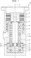
- FIG. 1 is a sectional view illustrating an example of a turbomolecular pump provided with a touchdown bearing.
- a turbomolecular pump 10 has a housing 11, a rotor shaft (rotating shaft) 12, rotor blades 13, magnetic bearings 14 and 15, a motor 16, and touchdown bearings 17 and 18.
- the housing 11 accommodates the rotor shaft 12, the rotor blades 13, the magnetic bearings 14 and 15, the motor 16, and the touchdown bearings 17 and 18.
- the housing 11 has an upper housing 11A and a lower housing 11B, which are linked to each other.
- the rotor shaft 12 has an axis of rotation C disposed in the up-down direction.
- the rotor shaft 12 is rotatably supported by the magnetic bearings 14 and 15 and the touchdown bearings 17 and 18.
- a disc-shaped flange 19 that protrudes outwards in the radial direction is provided at the lower end portion of the rotor shaft 12.
- the rotor shaft 12 is linked to the rotor blades 13 so as to be integrally rotatable.
- the magnetic bearings 14 and 15 have radial magnetic bearings 14 and axial magnetic bearings 15.
- the radial magnetic bearings 14 support the rotor shaft 12 at two positions in the up-down direction.
- the radial magnetic bearings 14 support the rotor shaft 12 from the outer side in the radial direction without physical contact as to the rotor shaft 12.
- the axial magnetic bearings 15 support the flange 19 of the rotor shaft 12 from both up and down sides without physical contact as to the flange 19.
- the motor 16 is disposed between the upper and lower radial magnetic bearings 14, and rotates the rotor shaft 12.
- the touchdown bearings 17 and 18 include an upper-side touchdown bearing 17 and a lower-side touchdown bearing (touchdown bearing according to the invention) 18.
- the upper-side touchdown bearing 17 is configured of a rolling bearing.
- the upper-side touchdown bearing 17 according to the present embodiment is a deep groove ball bearing provided with an inner ring, and an outer ring, and a plurality of balls.
- the lower-side touchdown bearing 18 supports the rotor shaft 12 in the up-down direction between the radial magnetic bearing 14 at the lower side and the flange 19.
- the lower-side touchdown bearing 18 is configured of a first rolling bearing 21 and a second rolling bearing 22.
- the first rolling bearing 21 and the second rolling bearing 22 are disposed arrayed in the up-down direction.
- the first rolling bearing 21 is disposed on the upper side of the second rolling bearing 22.
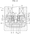
- FIG. 2 is a sectional view illustrating a lower portion side of the turbomolecular pump enlarged.
- FIG. 3 is a sectional view of the touchdown bearing.
- the first rolling bearing 21 and the second rolling bearing 22 are both angular contact ball bearings.
- the first rolling bearing 21 has a first inner ring 31, a first outer ring 32, and first balls 33.
- the second rolling bearing 22 has a second inner ring 41, a second outer ring 42, and second balls 43.
- Inner-ring raceways 31a and 41a are formed on the respective outer peripheral faces of the first and second inner rings 31 and 41.
- Inner-ring shoulder portions 31b and 41b are provided on the outer peripheral faces of the first and second inner rings 31 and 41, on both sides of the inner-ring raceways 31a and 41a in the axial direction.
- Outer-ring raceways 32a and 42a are formed on the respective inner peripheral faces of the first and second outer rings 32 and 42.
- the outer-ring raceways 32a and 42a are disposed on the outer side of the inner-ring raceways 31a and 41a in the radial direction, facing the inner-ring raceways 31a and 41a in the radial direction.
- Outer-ring shoulder portions 32b and 42b are provided adjacent to one side of the outer-ring raceways 32a and 42a in the axial direction at the inner peripheral faces of the first and second outer rings 32 and 42, and counter bores 32c and 42c are formed adjacent to the other side in the axial direction.
- the first and second balls 33 and 43 are arrayed between the inner-ring raceways 31a and 41a and the outer-ring raceways 32a and 42a in the radial direction.
- the first and second inner rings 31 and 41 and the first and second outer rings 32 and 42 are formed of stainless steels such as SUS440C (Japanese Industrial Standards) or the like, bearing steels such as SUJ2 (Japanese Industrial Standards) bearing steel or the like, or high speed tool steels such as SKH4 (Japanese Industrial Standards) high speed tool steel or the like, for example.
- the first and second balls 33 and 43 are formed of metal such as stainless steel or the like, or of ceramic such as silicon nitride or the like, for example. In the present embodiment, lightweight ceramic first and second balls 33 and 43 are employed.
- the first rolling bearing 21 and the second rolling bearing 22 according to the present embodiment are full complement rolling bearings that are not provided with cages.
- the first and second inner rings 31 and 41 are arrayed with a gap as to the rotor shaft 12 in the radial direction. This gap is smaller than a gap between the inner peripheral faces of the radial magnetic bearings 14 and the outer peripheral face of the rotor shaft 12.
- the first and second inner rings 31 and 41 come into contact with the rotor shaft 12 and rotate.
- a supported portion 12a supported by the lower-side touchdown bearing 18 is provided to the lower portion of the rotor shaft 12.
- a large-diameter portion 12b that has a larger outer diameter than the outer diameter of the supported portion 12a is provided to the upper side of the supported portion 12a.
- a stepped portion 12c is provided between the supported portion 12a and the large-diameter portion 12b, and the upper face of the first inner ring 31 is in contact with the stepped portion 12c.
- a small-diameter portion 12d that has a smaller outer diameter than the outer diameter of the supported portion 12a is provided to the lower side of the supported portion 12a.
- a ring-shaped first positioning member 35 is attached to this small-diameter portion 12d.
- the lower face of the second inner ring 41 is in contact with the first positioning member 35. Accordingly, the first inner ring 31 and the second inner ring 41 are clamped from above and below by the stepped portion 12c and the first positioning member 35, whereby the positions thereof in the direction of the axis of rotation of the rotor shaft 12 are set.
- the first outer ring 32 and the second outer ring 42 are attached to part of the housing 11.
- the housing 11 has the upper housing 11A, and the lower housing 11B that is linked to the lower end of the upper housing 11A.
- the lower housing 11B has a cylindrical bearing support member 36 that supports the axial magnetic bearing 15 and the lower-side touchdown bearing 18.
- the outer peripheral faces of the first outer ring 32 and the second outer ring 42 are fit to the inner peripheral face of the bearing support member 36 by clearance fitting.
- a ring-shaped second positioning member 37 is attached to the upper face of the bearing support member 36.
- the second positioning member 37 presses the first outer ring 32 from above.
- a supporting protrusion 38 that protrudes inward in the radial direction is provided to the inner peripheral face of the bearing support member 36.
- the supporting protrusion 38 supports the second outer ring 42 from the lower side. Accordingly, the first outer ring 32 and the second outer ring 42 are clamped from above and below by the second positioning member 37 and the supporting protrusion 38, whereby the positions thereof in the direction of the axis of rotation of the rotor shaft 12 are set.
- the first balls 33 of the first rolling bearing 21 are in contact with the first inner ring 31 and the first outer ring 32 at a first contact angle ⁇ 1.
- the second balls 43 of the second rolling bearing 22 are in contact with the second inner ring 41 and the second outer ring 42 at a second contact angle ⁇ 2.
- the first rolling bearing 21 and the second rolling bearing 22 are laid out so that the contact angles ⁇ 1 and ⁇ 2 are opposite to each other in the up-down direction.
- first outer ring 32 and the first balls 33 of the first rolling bearing 21 have the contact angle ⁇ 1 to the upper side as to the radial direction orthogonal to the axis of rotation C
- second outer ring 42 and the second balls 43 of the second rolling bearing 22 have the contact angle ⁇ 2 to the lower side as to the radial direction orthogonal to the axis of rotation C.
- the first rolling bearing 21 and the second rolling bearing 22 according to the present embodiment are arrayed in a so-called duplexed face-to-face relation.
- the rotor shaft 12 falls downward under its own weight.
- a downward axial load is applied to the lower-side touchdown bearing 18 (indicated by outline arrows in FIG. 3 ), and the second rolling bearing 22 receives this axial load.
- the second balls 43 of the second rolling bearing 22, and the second inner ring 41 and the second outer ring 42 are in strong contact, and hardly any slippage occurs therebetween.
- the first rolling bearing 21 does not receive the downward axial load, and accordingly the first balls 33 and the first inner ring 31 and the first outer ring 32 are not in strong contact, and slippage occurs therebetween more readily.
- the first contact angle ⁇ 1 at the first rolling bearing 21 is smaller than the second contact angle ⁇ 2 at the second rolling bearing 22, and accordingly the radial load accompanying rotation of the rotor shaft 12 is more readily applied to the first rolling bearing 21 than the axial load. Accordingly, the first balls 33, and the first inner ring 31 and the first outer ring 32, can be brought into strong contact in comparison with when the first contact angle ⁇ 1 and the second contact angle ⁇ 2 are the same, and slippage occurring therebetween can be suppressed correspondingly. Thus, damage to the first balls 33, the first inner ring 31, and the first outer ring 32 can be suppressed.
- the first balls 33 according to the present embodiment are formed of ceramic, and are lighter as compared to metal balls. Accordingly, the first balls 33 rotate following the first inner ring 31 more readily, and slippage between the first balls 33, and the first inner ring 31 and the first outer ring 32, can be further suppressed.
- the first contact angle ⁇ 1 at the first rolling bearing 21 can be set to no less than 5° and smaller than 20°, for example.
- second contact angle ⁇ 2 at the second rolling bearing 22 can be set to no less than 20° and no more than 30°.
- the first contact angle ⁇ 1 has the relation of the following Expression (1) as to the second contact angle ⁇ 2.
- the load performance of downward axial load from the rotor shaft 12 at the second rolling bearing 22 can be improved, and slippage between the first balls 33 in the first rolling bearing 21, and the first inner ring 31 and the first outer ring 32, can be effectively suppressed.
- FIG. 4 is a sectional view of a touchdown bearing according to another embodiment.
- the diameter of the first balls 33 of the first rolling bearing 21 is smaller than that of the second balls 43 of the second rolling bearing 22.
- Other configurations are the same as those of the above embodiment.
- the first balls 33 are smaller in diameter than the second balls 43, and are formed more lightweight. Accordingly, the first balls 33 can be made to rotate following the first inner ring 31 more readily, and slippage between the first balls 33, and the first inner ring 31 and the first outer ring 32, can be suppressed.
- first rolling bearing 21 of the lower-side touchdown bearing 18 has been described as being an angular contact ball bearing in which the counter bore 32c is formed in the first outer ring 32, this may be a deep groove ball bearing in which the first balls 33 come into contact with the inner-ring raceway 31a and the outer-ring raceway 32a with a contact angle.
- the first rolling bearing 21 and the second rolling bearing 22 of the lower-side touchdown bearing 18 may be used duplexed back-to-back.
- the contact angle of the second rolling bearing 22 at the lower side which does not receive the axial load from the rotor shaft 12, may be made to be smaller than the contact angle of the first rolling bearing 21 at the upper side, which receives the axial load from the rotor shaft 12.
Landscapes
- Engineering & Computer Science (AREA)
- General Engineering & Computer Science (AREA)
- Mechanical Engineering (AREA)
- Rolling Contact Bearings (AREA)
- Magnetic Bearings And Hydrostatic Bearings (AREA)
Abstract
A touchdown bearing (18) includes two rolling bearings (21, 22) disposed arrayed in an up-down direction. The rolling bearings (21, 22) include inner rings (31, 41) that have inner-ring raceways, outer rings (32, 42) that have outer-ring raceways, and a plurality of balls (33, 43) that are disposed between the inner-ring raceways and the outer-ring raceways, and that come into contact with the inner-ring raceways and the outer-ring raceways at contact angles. The two rolling bearings (21, 22) are laid out with the contact angles opposite to each other in the up-down direction. The contact angle of a first rolling bearing (21) out of the two rolling bearings (21, 22) is smaller than the contact angle of a second rolling bearing (22) out of the two rolling bearings (21, 22).
Description
- The invention relates to a touchdown bearing.
- Generally, a turbomolecular pump is provided with a rotor shaft having an axis of rotation arranged in the up-down direction, and rotor blades that integrally rotate with the rotor shaft. The rotor shaft is supported without physical contact by a magnetic bearing. The turbomolecular pump is further provided with a touchdown bearing to support the rotor shaft instead of the magnetic bearings when the functions of the magnetic bearing stop due to a malfunction, power outage, or the like (e.g., see
Japanese Unexamined Patent Application Publication No. 2010-190400 JP 2010-190400 A JP 2010-190400 A - Of the touchdown bearing described in
JP 2010-190400 A - The invention suppresses slippage between the balls and the raceway of a rolling bearing configuring a touchdown bearing.
- An aspect of the invention is a touchdown bearing. The touchdown bearing rotatably supports a rotating shaft having an axis of rotation disposed in an up-down direction. The touchdown bearing includes two rolling bearings disposed arrayed in the up-down direction. The rolling bearings include inner rings that have inner-ring raceways, outer rings that are disposed on an outer side of the inner-ring raceways in a radial direction, and that have outer-ring raceways, and a plurality of balls that are disposed between the inner-ring raceways and the outer-ring raceways, and that come into contact with the inner-ring raceways and the outer-ring raceways at contact angles. The two rolling bearings are laid out with the contact angles opposite to each other in the up-down direction. The contact angle of a first rolling bearing out of the two rolling bearings is smaller than the contact angle of a second rolling bearing out of the two rolling bearings. The first rolling bearing is a rolling bearing that does not receive downward axial load from the rotating shaft, and the second rolling bearing is a rolling bearing that receives the axial load.
- According to the above configuration, slippage between the balls, and the inner-ring raceway and the outer-ring raceway, in the first rolling bearing that does not receive the downward axial load from the rotating shaft, can be suppressed. Accordingly, damage to the balls, and the inner-ring raceway and the outer-ring raceway, in the first rolling bearing, can be suppressed.
- In the touchdown bearing, an outer diameter of the balls of the first rolling bearing may be smaller than an outer diameter of the balls of the second rolling bearing. According to this configuration, the balls in the first rolling bearing can be made lightweight, the balls can be made to rotate following rotation of the inner ring more readily, and slippage between the balls, and the inner-ring raceway and the outer-ring raceway, can be suppressed.
- In the touchdown bearing, the contact angle of the first rolling bearing may be 1/4 to 1/6 of the contact angle of the second rolling bearing. According to the above configuration, the contact angle of the other rolling bearing is made to be sufficiently large and the load capacity as to the downward axial load from the rotating shaft is increased, while the contact angle of the first rolling bearing is made to be sufficiently small and slippage between the balls, and the inner-ring raceway and the outer-ring raceway, can be effectively suppressed.
- With the above configuration, slippage between the balls and the raceway of a rolling bearing configuring a touchdown bearing can be suppressed.
- Features, advantages, and technical and industrial significance of exemplary embodiments of the invention will be described below with reference to the accompanying drawings, in which like signs denote like elements, and wherein:
-
FIG. 1 is a sectional view illustrating an example of a turbomolecular pump provided with a touchdown bearing according to an embodiment of the invention; -
FIG. 2 is a sectional view illustrating a lower portion side of the turbomolecular pump enlarged; -
FIG. 3 is a sectional view of the touchdown bearing; and -
FIG. 4 is a sectional view of a touchdown bearing according to another embodiment. -
FIG. 1 is a sectional view illustrating an example of a turbomolecular pump provided with a touchdown bearing. Aturbomolecular pump 10 has a housing 11, a rotor shaft (rotating shaft) 12,rotor blades 13,magnetic bearings motor 16, andtouchdown bearings - The housing 11 accommodates the
rotor shaft 12, therotor blades 13, themagnetic bearings motor 16, and thetouchdown bearings upper housing 11A and alower housing 11B, which are linked to each other. - The
rotor shaft 12 has an axis of rotation C disposed in the up-down direction. Therotor shaft 12 is rotatably supported by themagnetic bearings touchdown bearings shaped flange 19 that protrudes outwards in the radial direction is provided at the lower end portion of therotor shaft 12. Therotor shaft 12 is linked to therotor blades 13 so as to be integrally rotatable. - The
magnetic bearings magnetic bearings 14 and axialmagnetic bearings 15. The radialmagnetic bearings 14 support therotor shaft 12 at two positions in the up-down direction. When functioning normally, the radialmagnetic bearings 14 support therotor shaft 12 from the outer side in the radial direction without physical contact as to therotor shaft 12. When functioning normally, the axialmagnetic bearings 15 support theflange 19 of therotor shaft 12 from both up and down sides without physical contact as to theflange 19. Themotor 16 is disposed between the upper and lower radialmagnetic bearings 14, and rotates therotor shaft 12. - The
touchdown bearings - The lower-side touchdown bearing 18 supports the
rotor shaft 12 in the up-down direction between the radialmagnetic bearing 14 at the lower side and theflange 19. The lower-side touchdown bearing 18 is configured of a first rolling bearing 21 and a second rolling bearing 22. The first rolling bearing 21 and the second rollingbearing 22 are disposed arrayed in the up-down direction. The first rollingbearing 21 is disposed on the upper side of the second rolling bearing 22. -
FIG. 2 is a sectional view illustrating a lower portion side of the turbomolecular pump enlarged.FIG. 3 is a sectional view of the touchdown bearing. The first rolling bearing 21 and the second rolling bearing 22 are both angular contact ball bearings. The first rolling bearing 21 has a firstinner ring 31, a firstouter ring 32, andfirst balls 33. The second rolling bearing 22 has a secondinner ring 41, a secondouter ring 42, andsecond balls 43. - Inner-
ring raceways inner rings ring shoulder portions inner rings ring raceways - Outer-
ring raceways outer rings ring raceways ring raceways ring raceways ring shoulder portions ring raceways outer rings counter bores second balls ring raceways ring raceways - The first and second
inner rings outer rings second balls second balls - The first and second
inner rings rotor shaft 12 in the radial direction. This gap is smaller than a gap between the inner peripheral faces of the radialmagnetic bearings 14 and the outer peripheral face of therotor shaft 12. When functions of the radialmagnetic bearings 14 stop due to a malfunction, power outage, or the like, i.e., in a state of abnormal operations, the first and secondinner rings rotor shaft 12 and rotate. - A supported
portion 12a supported by the lower-side touchdown bearing 18 is provided to the lower portion of therotor shaft 12. A large-diameter portion 12b that has a larger outer diameter than the outer diameter of the supportedportion 12a is provided to the upper side of the supportedportion 12a. A steppedportion 12c is provided between the supportedportion 12a and the large-diameter portion 12b, and the upper face of the firstinner ring 31 is in contact with the steppedportion 12c. - A small-
diameter portion 12d that has a smaller outer diameter than the outer diameter of the supportedportion 12a is provided to the lower side of the supportedportion 12a. A ring-shaped first positioningmember 35 is attached to this small-diameter portion 12d. The lower face of the secondinner ring 41 is in contact with thefirst positioning member 35. Accordingly, the firstinner ring 31 and the secondinner ring 41 are clamped from above and below by the steppedportion 12c and thefirst positioning member 35, whereby the positions thereof in the direction of the axis of rotation of therotor shaft 12 are set. - The first
outer ring 32 and the secondouter ring 42 are attached to part of the housing 11. The housing 11 has theupper housing 11A, and thelower housing 11B that is linked to the lower end of theupper housing 11A. Thelower housing 11B has a cylindricalbearing support member 36 that supports the axialmagnetic bearing 15 and the lower-side touchdown bearing 18. The outer peripheral faces of the firstouter ring 32 and the secondouter ring 42 are fit to the inner peripheral face of thebearing support member 36 by clearance fitting. Thus, due to the outer peripheral faces of the first and secondouter rings bearing support member 36 by clearance fitting, assembly of the first and secondouter rings bearing support member 36 is facilitated, and thermal expansion of the first and secondouter rings inner rings second balls outer rings bearing support member 36. - A ring-shaped
second positioning member 37 is attached to the upper face of thebearing support member 36. Thesecond positioning member 37 presses the firstouter ring 32 from above. A supportingprotrusion 38 that protrudes inward in the radial direction is provided to the inner peripheral face of thebearing support member 36. The supportingprotrusion 38 supports the secondouter ring 42 from the lower side. Accordingly, the firstouter ring 32 and the secondouter ring 42 are clamped from above and below by thesecond positioning member 37 and the supportingprotrusion 38, whereby the positions thereof in the direction of the axis of rotation of therotor shaft 12 are set. - As illustrated in
FIG. 3 , thefirst balls 33 of the first rolling bearing 21 are in contact with the firstinner ring 31 and the firstouter ring 32 at a first contact angle θ1. Thesecond balls 43 of the second rolling bearing 22 are in contact with the secondinner ring 41 and the secondouter ring 42 at a second contact angle θ2. The first rolling bearing 21 and the second rolling bearing 22 are laid out so that the contact angles θ1 and θ2 are opposite to each other in the up-down direction. Specifically, the firstouter ring 32 and thefirst balls 33 of the first rolling bearing 21 have the contact angle θ1 to the upper side as to the radial direction orthogonal to the axis of rotation C, and the secondouter ring 42 and thesecond balls 43 of the second rolling bearing 22 have the contact angle θ2 to the lower side as to the radial direction orthogonal to the axis of rotation C. Accordingly, the first rolling bearing 21 and the second rolling bearing 22 according to the present embodiment are arrayed in a so-called duplexed face-to-face relation. - When the functions of the radial
magnetic bearings 14 and the axialmagnetic bearings 15 stop due to a malfunction, power outage, or the like, i.e., in a state of abnormal operations, therotor shaft 12 falls downward under its own weight. At this time, a downward axial load is applied to the lower-side touchdown bearing 18 (indicated by outline arrows inFIG. 3 ), and the second rolling bearing 22 receives this axial load. Accordingly, thesecond balls 43 of the second rolling bearing 22, and the secondinner ring 41 and the secondouter ring 42 are in strong contact, and hardly any slippage occurs therebetween. As opposite to this, the first rolling bearing 21 does not receive the downward axial load, and accordingly thefirst balls 33 and the firstinner ring 31 and the firstouter ring 32 are not in strong contact, and slippage occurs therebetween more readily. - In the present embodiment, the first contact angle θ1 at the first rolling bearing 21 is smaller than the second contact angle θ2 at the second rolling bearing 22, and accordingly the radial load accompanying rotation of the
rotor shaft 12 is more readily applied to the first rolling bearing 21 than the axial load. Accordingly, thefirst balls 33, and the firstinner ring 31 and the firstouter ring 32, can be brought into strong contact in comparison with when the first contact angle θ1 and the second contact angle θ2 are the same, and slippage occurring therebetween can be suppressed correspondingly. Thus, damage to thefirst balls 33, the firstinner ring 31, and the firstouter ring 32 can be suppressed. - The
first balls 33 according to the present embodiment are formed of ceramic, and are lighter as compared to metal balls. Accordingly, thefirst balls 33 rotate following the firstinner ring 31 more readily, and slippage between thefirst balls 33, and the firstinner ring 31 and the firstouter ring 32, can be further suppressed. - The first contact angle θ1 at the first rolling bearing 21 can be set to no less than 5° and smaller than 20°, for example. As compared to this, second contact angle θ2 at the second rolling bearing 22 can be set to no less than 20° and no more than 30°. For example, when the first contact angle θ1 is 5°, the second contact angle θ2 can be set to no less than 20° and no more than 30°. In this case, the first contact angle θ1 has the relation of the following Expression (1) as to the second contact angle θ2.

- By setting the first and second contact angles θ1 and θ2 according to the relation shown in Expression (1), the load performance of downward axial load from the
rotor shaft 12 at the second rolling bearing 22 can be improved, and slippage between thefirst balls 33 in the first rolling bearing 21, and the firstinner ring 31 and the firstouter ring 32, can be effectively suppressed. -
FIG. 4 is a sectional view of a touchdown bearing according to another embodiment. In the lower-side touchdown bearing 18 in the present embodiment, the diameter of thefirst balls 33 of the first rolling bearing 21 is smaller than that of thesecond balls 43 of the second rolling bearing 22. Other configurations are the same as those of the above embodiment. - In the present embodiment, the
first balls 33 are smaller in diameter than thesecond balls 43, and are formed more lightweight. Accordingly, thefirst balls 33 can be made to rotate following the firstinner ring 31 more readily, and slippage between thefirst balls 33, and the firstinner ring 31 and the firstouter ring 32, can be suppressed. - The embodiments disclosed herein are exemplary in all points, and are not limiting. The scope of the invention is not limited to the above-described embodiments, and encompasses all modification within a range equivalent to configurations set forth in the Claims.
- For example, although the first rolling bearing 21 of the lower-side touchdown bearing 18 has been described as being an angular contact ball bearing in which the
counter bore 32c is formed in the firstouter ring 32, this may be a deep groove ball bearing in which thefirst balls 33 come into contact with the inner-ring raceway 31a and the outer-ring raceway 32a with a contact angle. - The first rolling bearing 21 and the second rolling bearing 22 of the lower-side touchdown bearing 18 may be used duplexed back-to-back. In this case, the contact angle of the second rolling bearing 22 at the lower side, which does not receive the axial load from the
rotor shaft 12, may be made to be smaller than the contact angle of the first rolling bearing 21 at the upper side, which receives the axial load from therotor shaft 12.
Claims (3)
- A touchdown bearing (18) that rotatably supports a rotating shaft having an axis of rotation disposed in an up-down direction, the touchdown bearing (18) characterized by comprising two rolling bearings (21, 22) disposed arrayed in the up-down direction, wherein
the rolling bearings (21, 22) include inner rings (31, 41) that have inner-ring raceways, outer rings (32, 42) that are disposed on an outer side of the inner-ring raceways in a radial direction, and that have outer-ring raceways, and a plurality of balls (33, 43) that are disposed between the inner-ring raceways and the outer-ring raceways, and that come into contact with the inner-ring raceways and the outer-ring raceways at contact angles,
the two rolling bearings (21, 22) are laid out with the contact angles opposite to each other in the up-down direction, and
the contact angle of a first rolling bearing (21) out of the two rolling bearings (21, 22) is smaller than the contact angle of a second rolling bearing (22) out of the two rolling bearings (21, 22), the first rolling bearing (21) is a rolling bearing that does not receive downward axial load from the rotating shaft, and the second rolling bearing (22) is a rolling bearing that receives the axial load. - The touchdown bearing (18) according to claim 1, characterized in that an outer diameter of the balls (33) of the first rolling bearing (21) is smaller than an outer diameter of the balls (43) of the second rolling bearing (22).
- The touchdown bearing (18) according to claim 1 or 2, characterized in that the contact angle of the first rolling bearing (21) is 1/4 to 1/6 of the contact angle of the second rolling bearing (22).
Applications Claiming Priority (1)
| Application Number | Priority Date | Filing Date | Title |
|---|---|---|---|
| JP2020096581A JP2021188713A (en) | 2020-06-03 | 2020-06-03 | Touchdown bearing |
Publications (1)
| Publication Number | Publication Date |
|---|---|
| EP3919767A1 true EP3919767A1 (en) | 2021-12-08 |
Family
ID=76250077
Family Applications (1)
| Application Number | Title | Priority Date | Filing Date |
|---|---|---|---|
| EP21177128.2A Withdrawn EP3919767A1 (en) | 2020-06-03 | 2021-06-01 | Touchdown bearing |
Country Status (2)
| Country | Link |
|---|---|
| EP (1) | EP3919767A1 (en) |
| JP (1) | JP2021188713A (en) |
Families Citing this family (1)
| Publication number | Priority date | Publication date | Assignee | Title |
|---|---|---|---|---|
| JP2023111002A (en) * | 2022-01-31 | 2023-08-10 | 株式会社Ihi | Composite bearings and compressors |
Citations (4)
| Publication number | Priority date | Publication date | Assignee | Title |
|---|---|---|---|---|
| DE4305289A1 (en) * | 1992-02-27 | 1993-09-02 | Skf Usa Inc | Bearing for high speed shaft in screw compressor - has sets of inclined ball bearings with different contact angles |
| JPH07238926A (en) * | 1994-02-28 | 1995-09-12 | Nippon Seiko Kk | Ball bearing device |
| JP2010190400A (en) | 2009-02-20 | 2010-09-02 | Nsk Ltd | Touchdown bearing |
| DE102013203981A1 (en) * | 2013-03-08 | 2014-09-11 | Aktiebolaget Skf | Double row angular contact ball bearing |
-
2020
- 2020-06-03 JP JP2020096581A patent/JP2021188713A/en active Pending
-
2021
- 2021-06-01 EP EP21177128.2A patent/EP3919767A1/en not_active Withdrawn
Patent Citations (4)
| Publication number | Priority date | Publication date | Assignee | Title |
|---|---|---|---|---|
| DE4305289A1 (en) * | 1992-02-27 | 1993-09-02 | Skf Usa Inc | Bearing for high speed shaft in screw compressor - has sets of inclined ball bearings with different contact angles |
| JPH07238926A (en) * | 1994-02-28 | 1995-09-12 | Nippon Seiko Kk | Ball bearing device |
| JP2010190400A (en) | 2009-02-20 | 2010-09-02 | Nsk Ltd | Touchdown bearing |
| DE102013203981A1 (en) * | 2013-03-08 | 2014-09-11 | Aktiebolaget Skf | Double row angular contact ball bearing |
Also Published As
| Publication number | Publication date |
|---|---|
| JP2021188713A (en) | 2021-12-13 |
Similar Documents
| Publication | Publication Date | Title |
|---|---|---|
| EP3004653B1 (en) | Rotating machine with at least one active magnetic bearing and spaced auxiliary rolling bearings | |
| EP2808551B1 (en) | Rotating machine with at least one active magnetic bearing and auxiliary rolling bearings | |
| JP2016095026A (en) | Inclined contact self-aligning toroidal rolling bearings | |
| EP1715203A1 (en) | Oblique contact ball bearing and turbocharger | |
| WO2000034674A1 (en) | Thrust bearing arrangement | |
| US6661143B1 (en) | Bearing unit with magnetic bearing protection upon rotation stoppage | |
| US20050058378A1 (en) | Bearing cup rotational lock assembly | |
| US10302128B2 (en) | Combined ball bearing, main spindle device, and machine tool | |
| JPH11264420A (en) | Rolling bearing | |
| JP2021188713A (en) | Touchdown bearing | |
| JP2005061433A (en) | Multi-point contact ball bearing | |
| EP3851688B1 (en) | Spindle device | |
| JP3572710B2 (en) | Radial ball bearing preloading method and radial ball bearing device with preload | |
| US12416333B2 (en) | Bearing assembly | |
| JP2008032147A (en) | Rotating shaft supporting structure of wind power generator | |
| JP2002339970A (en) | Magnetic bearing device, and turbo-molecular pump | |
| US11592057B2 (en) | Bearing device and rotary device using bearing device | |
| US20250012325A1 (en) | An angular contact self-aligning toroidal rolling element bearing | |
| WO2023248266A1 (en) | Double-row deep-groove ball bearing and magnetic bearing device | |
| JP2019173888A (en) | Angular contact ball bearing | |
| JP2024167613A (en) | Ball bearings | |
| JP2023111002A (en) | Composite bearings and compressors | |
| JP7014561B2 (en) | Rolling bearings | |
| JPH11101236A (en) | Touchdown bearing device | |
| JP2006177445A (en) | Double-row automatic aligned roller bearing |
Legal Events
| Date | Code | Title | Description |
|---|---|---|---|
| PUAI | Public reference made under article 153(3) epc to a published international application that has entered the european phase |
Free format text: ORIGINAL CODE: 0009012 |
|
| STAA | Information on the status of an ep patent application or granted ep patent |
Free format text: STATUS: THE APPLICATION HAS BEEN PUBLISHED |
|
| AK | Designated contracting states |
Kind code of ref document: A1 Designated state(s): AL AT BE BG CH CY CZ DE DK EE ES FI FR GB GR HR HU IE IS IT LI LT LU LV MC MK MT NL NO PL PT RO RS SE SI SK SM TR |
|
| B565 | Issuance of search results under rule 164(2) epc |
Effective date: 20211014 |
|
| STAA | Information on the status of an ep patent application or granted ep patent |
Free format text: STATUS: THE APPLICATION IS DEEMED TO BE WITHDRAWN |
|
| 18D | Application deemed to be withdrawn |
Effective date: 20220609 |