EP3919745B1 - Compressor and refrigeration cycle device - Google Patents
Compressor and refrigeration cycle device Download PDFInfo
- Publication number
- EP3919745B1 EP3919745B1 EP19913571.6A EP19913571A EP3919745B1 EP 3919745 B1 EP3919745 B1 EP 3919745B1 EP 19913571 A EP19913571 A EP 19913571A EP 3919745 B1 EP3919745 B1 EP 3919745B1
- Authority
- EP
- European Patent Office
- Prior art keywords
- suction
- center
- suction pipe
- pipe
- compressor
- Prior art date
- Legal status (The legal status is an assumption and is not a legal conclusion. Google has not performed a legal analysis and makes no representation as to the accuracy of the status listed.)
- Active
Links
Images



Classifications
-
- F—MECHANICAL ENGINEERING; LIGHTING; HEATING; WEAPONS; BLASTING
- F25—REFRIGERATION OR COOLING; COMBINED HEATING AND REFRIGERATION SYSTEMS; HEAT PUMP SYSTEMS; MANUFACTURE OR STORAGE OF ICE; LIQUEFACTION SOLIDIFICATION OF GASES
- F25B—REFRIGERATION MACHINES, PLANTS OR SYSTEMS; COMBINED HEATING AND REFRIGERATION SYSTEMS; HEAT PUMP SYSTEMS
- F25B31/00—Compressor arrangements
- F25B31/02—Compressor arrangements of motor-compressor units
- F25B31/026—Compressor arrangements of motor-compressor units with compressor of rotary type
-
- F—MECHANICAL ENGINEERING; LIGHTING; HEATING; WEAPONS; BLASTING
- F25—REFRIGERATION OR COOLING; COMBINED HEATING AND REFRIGERATION SYSTEMS; HEAT PUMP SYSTEMS; MANUFACTURE OR STORAGE OF ICE; LIQUEFACTION SOLIDIFICATION OF GASES
- F25B—REFRIGERATION MACHINES, PLANTS OR SYSTEMS; COMBINED HEATING AND REFRIGERATION SYSTEMS; HEAT PUMP SYSTEMS
- F25B43/00—Arrangements for separating or purifying gases or liquids; Arrangements for vaporising the residuum of liquid refrigerant, e.g. by heat
- F25B43/006—Accumulators
-
- F—MECHANICAL ENGINEERING; LIGHTING; HEATING; WEAPONS; BLASTING
- F04—POSITIVE - DISPLACEMENT MACHINES FOR LIQUIDS; PUMPS FOR LIQUIDS OR ELASTIC FLUIDS
- F04C—ROTARY-PISTON, OR OSCILLATING-PISTON, POSITIVE-DISPLACEMENT MACHINES FOR LIQUIDS; ROTARY-PISTON, OR OSCILLATING-PISTON, POSITIVE-DISPLACEMENT PUMPS
- F04C18/00—Rotary-piston pumps specially adapted for elastic fluids
- F04C18/30—Rotary-piston pumps specially adapted for elastic fluids having the characteristics covered by two or more of groups F04C18/02, F04C18/08, F04C18/22, F04C18/24, F04C18/48, or having the characteristics covered by one of these groups together with some other type of movement between co-operating members
- F04C18/34—Rotary-piston pumps specially adapted for elastic fluids having the characteristics covered by two or more of groups F04C18/02, F04C18/08, F04C18/22, F04C18/24, F04C18/48, or having the characteristics covered by one of these groups together with some other type of movement between co-operating members having the movement defined in group F04C18/08 or F04C18/22 and relative reciprocation between the co-operating members
- F04C18/356—Rotary-piston pumps specially adapted for elastic fluids having the characteristics covered by two or more of groups F04C18/02, F04C18/08, F04C18/22, F04C18/24, F04C18/48, or having the characteristics covered by one of these groups together with some other type of movement between co-operating members having the movement defined in group F04C18/08 or F04C18/22 and relative reciprocation between the co-operating members with vanes reciprocating with respect to the outer member
- F04C18/3562—Rotary-piston pumps specially adapted for elastic fluids having the characteristics covered by two or more of groups F04C18/02, F04C18/08, F04C18/22, F04C18/24, F04C18/48, or having the characteristics covered by one of these groups together with some other type of movement between co-operating members having the movement defined in group F04C18/08 or F04C18/22 and relative reciprocation between the co-operating members with vanes reciprocating with respect to the outer member the inner and outer member being in contact along one line or continuous surfaces substantially parallel to the axis of rotation
- F04C18/3564—Rotary-piston pumps specially adapted for elastic fluids having the characteristics covered by two or more of groups F04C18/02, F04C18/08, F04C18/22, F04C18/24, F04C18/48, or having the characteristics covered by one of these groups together with some other type of movement between co-operating members having the movement defined in group F04C18/08 or F04C18/22 and relative reciprocation between the co-operating members with vanes reciprocating with respect to the outer member the inner and outer member being in contact along one line or continuous surfaces substantially parallel to the axis of rotation the surfaces of the inner and outer member, forming the working space, being surfaces of revolution
-
- F—MECHANICAL ENGINEERING; LIGHTING; HEATING; WEAPONS; BLASTING
- F04—POSITIVE - DISPLACEMENT MACHINES FOR LIQUIDS; PUMPS FOR LIQUIDS OR ELASTIC FLUIDS
- F04C—ROTARY-PISTON, OR OSCILLATING-PISTON, POSITIVE-DISPLACEMENT MACHINES FOR LIQUIDS; ROTARY-PISTON, OR OSCILLATING-PISTON, POSITIVE-DISPLACEMENT PUMPS
- F04C23/00—Combinations of two or more pumps, each being of rotary-piston or oscillating-piston type, specially adapted for elastic fluids; Pumping installations specially adapted for elastic fluids; Multi-stage pumps specially adapted for elastic fluids
- F04C23/001—Combinations of two or more pumps, each being of rotary-piston or oscillating-piston type, specially adapted for elastic fluids; Pumping installations specially adapted for elastic fluids; Multi-stage pumps specially adapted for elastic fluids of similar working principle
-
- F—MECHANICAL ENGINEERING; LIGHTING; HEATING; WEAPONS; BLASTING
- F04—POSITIVE - DISPLACEMENT MACHINES FOR LIQUIDS; PUMPS FOR LIQUIDS OR ELASTIC FLUIDS
- F04C—ROTARY-PISTON, OR OSCILLATING-PISTON, POSITIVE-DISPLACEMENT MACHINES FOR LIQUIDS; ROTARY-PISTON, OR OSCILLATING-PISTON, POSITIVE-DISPLACEMENT PUMPS
- F04C23/00—Combinations of two or more pumps, each being of rotary-piston or oscillating-piston type, specially adapted for elastic fluids; Pumping installations specially adapted for elastic fluids; Multi-stage pumps specially adapted for elastic fluids
- F04C23/008—Hermetic pumps
-
- F—MECHANICAL ENGINEERING; LIGHTING; HEATING; WEAPONS; BLASTING
- F04—POSITIVE - DISPLACEMENT MACHINES FOR LIQUIDS; PUMPS FOR LIQUIDS OR ELASTIC FLUIDS
- F04C—ROTARY-PISTON, OR OSCILLATING-PISTON, POSITIVE-DISPLACEMENT MACHINES FOR LIQUIDS; ROTARY-PISTON, OR OSCILLATING-PISTON, POSITIVE-DISPLACEMENT PUMPS
- F04C29/00—Component parts, details or accessories of pumps or pumping installations, not provided for in groups F04C18/00 - F04C28/00
- F04C29/12—Arrangements for admission or discharge of the working fluid, e.g. constructional features of the inlet or outlet
-
- F—MECHANICAL ENGINEERING; LIGHTING; HEATING; WEAPONS; BLASTING
- F25—REFRIGERATION OR COOLING; COMBINED HEATING AND REFRIGERATION SYSTEMS; HEAT PUMP SYSTEMS; MANUFACTURE OR STORAGE OF ICE; LIQUEFACTION SOLIDIFICATION OF GASES
- F25B—REFRIGERATION MACHINES, PLANTS OR SYSTEMS; COMBINED HEATING AND REFRIGERATION SYSTEMS; HEAT PUMP SYSTEMS
- F25B1/00—Compression machines, plants or systems with non-reversible cycle
- F25B1/10—Compression machines, plants or systems with non-reversible cycle with multi-stage compression
-
- F—MECHANICAL ENGINEERING; LIGHTING; HEATING; WEAPONS; BLASTING
- F25—REFRIGERATION OR COOLING; COMBINED HEATING AND REFRIGERATION SYSTEMS; HEAT PUMP SYSTEMS; MANUFACTURE OR STORAGE OF ICE; LIQUEFACTION SOLIDIFICATION OF GASES
- F25B—REFRIGERATION MACHINES, PLANTS OR SYSTEMS; COMBINED HEATING AND REFRIGERATION SYSTEMS; HEAT PUMP SYSTEMS
- F25B41/00—Fluid-circulation arrangements
- F25B41/40—Fluid line arrangements
-
- F—MECHANICAL ENGINEERING; LIGHTING; HEATING; WEAPONS; BLASTING
- F04—POSITIVE - DISPLACEMENT MACHINES FOR LIQUIDS; PUMPS FOR LIQUIDS OR ELASTIC FLUIDS
- F04C—ROTARY-PISTON, OR OSCILLATING-PISTON, POSITIVE-DISPLACEMENT MACHINES FOR LIQUIDS; ROTARY-PISTON, OR OSCILLATING-PISTON, POSITIVE-DISPLACEMENT PUMPS
- F04C2240/00—Components
- F04C2240/80—Other components
- F04C2240/804—Accumulators for refrigerant circuits
-
- F—MECHANICAL ENGINEERING; LIGHTING; HEATING; WEAPONS; BLASTING
- F25—REFRIGERATION OR COOLING; COMBINED HEATING AND REFRIGERATION SYSTEMS; HEAT PUMP SYSTEMS; MANUFACTURE OR STORAGE OF ICE; LIQUEFACTION SOLIDIFICATION OF GASES
- F25B—REFRIGERATION MACHINES, PLANTS OR SYSTEMS; COMBINED HEATING AND REFRIGERATION SYSTEMS; HEAT PUMP SYSTEMS
- F25B2500/00—Problems to be solved
- F25B2500/01—Geometry problems, e.g. for reducing size
-
- F—MECHANICAL ENGINEERING; LIGHTING; HEATING; WEAPONS; BLASTING
- F25—REFRIGERATION OR COOLING; COMBINED HEATING AND REFRIGERATION SYSTEMS; HEAT PUMP SYSTEMS; MANUFACTURE OR STORAGE OF ICE; LIQUEFACTION SOLIDIFICATION OF GASES
- F25B—REFRIGERATION MACHINES, PLANTS OR SYSTEMS; COMBINED HEATING AND REFRIGERATION SYSTEMS; HEAT PUMP SYSTEMS
- F25B2500/00—Problems to be solved
- F25B2500/05—Cost reduction
Definitions
- a refrigeration cycle device includes a compressor which compresses a gaseous refrigerant.
- the compressor includes a compressor main body and an accumulator.
- the accumulator performs gas-liquid separation of a refrigerant and supplies a gaseous refrigerant to the compressor main body.
- Compressors are required to be made compact.
- a problem to be solved by the present invention is to provide a compressor and a refrigeration cycle device which can be made compact.
- an X direction, a Y direction, and a Z direction of an orthogonal coordinate system will be defined as follows.
- the X direction is a direction in which a compressor main body 10 and an accumulator 50 are aligned
- a +X direction is a direction from the compressor main body 10 toward the accumulator 50.
- the Z direction is a direction parallel to a central axis of the compressor main body 10
- a +Z direction is a direction from a compression mechanism unit 20 to an electric motor unit 15.
- the Y direction is a direction perpendicular to the X direction and the Z direction.
- the X direction and Y direction are horizontal directions.
- the Z direction is a vertical direction
- the +Z direction is vertically upward.
- the heat absorber 5 evaporates the low-temperature and low-pressure liquid refrigerant sent from the expansion device 4 to convert the low-temperature and low-pressure liquid refrigerant into a low-pressure gaseous refrigerant.
- evaporation of the low-pressure liquid refrigerant takes evaporation heat from the surroundings, and thus the surroundings are cooled. Further, the low-pressure gaseous refrigerant that has passed through the heat absorber 5 is taken into the compressor 2 described above.
- a refrigerant serving as a working fluid circulates while changing its phase between a gaseous refrigerant and a liquid refrigerant, and heating, cooling, or the like is performed by utilizing such heat radiation and heat absorption.
- the compressor 2 of the embodiment will be described.
- the compressor 2 includes the compressor main body 10 and the accumulator 50.
- the compressor main body 10 includes a shaft 13, the electric motor unit 15 that rotates the shaft 13, a plurality of compression mechanism units 20 that compress a gaseous refrigerant due to rotation of the shaft 13, and a cylindrical case 11 that houses the shaft 13, the electric motor unit 15, and the compression mechanism units 20.
- the shaft 13 is disposed along the central axis of the compressor main body 10.
- the electric motor unit 15 is disposed in the +Z direction of the shaft 13.
- the electric motor unit 15 includes a stator 15a and a rotor 15b.
- the stator 15a is fixed to an inner circumferential surface of the case 11.
- the rotor 15b is fixed to an outer circumferential surface of the shaft 13.
- the electric motor unit 15 rotates the shaft 13 inside the case 11.
- the case 11 is formed in a cylindrical shape with both end portions closed.
- the case 11 includes a discharge part 19 at an upper end portion.
- the discharge part 19 is formed by a pipe and is disposed along a central axis of the case 11.
- the discharge part 19 has a discharge port at an upper end portion. The discharge part 19 discharges the gaseous refrigerant inside the case 11 from the discharge port.
- the plurality of compression mechanism units 20 are disposed in a -Z direction of the shaft 13.
- the plurality of compression mechanism units 20 include three compression mechanism units 20 including, for example, a first compression mechanism unit 21, a second compression mechanism unit 22, and a third compression mechanism unit 23.
- the first compression mechanism unit 21, the second compression mechanism unit 22, and the third compression mechanism unit 23 are disposed to be aligned in that order from the +Z direction to the -Z direction.
- the first compression mechanism unit 21 is positioned uppermost in the +Z direction among the plurality of compression mechanism units 20.
- Configurations of the second compression mechanism unit 22 and the third compression mechanism unit 23 are the same as those of the first compression mechanism unit 21 except for a direction of eccentricity of an eccentric part 32.
- the first compression mechanism unit 21 includes the eccentric part 32, a roller 33, a cylinder 35, a bearing 17, and a partition plate 25.
- the roller 33 is formed in a cylindrical shape and is disposed along an outer circumference of the eccentric part 32.
- the cylinder 35 is fixed to a frame 20a.
- An outer circumferential surface of the frame 20a is fixed to an inner circumferential surface of the case 11.
- the cylinder 35 includes a cylinder chamber 36, a vane (not illustrated), and a suction hole 38.
- the cylinder chamber 36 houses the eccentric part 32 and the roller 33 inside.
- the vane is housed in a vane groove formed in the cylinder 35 and can advance into and retreat from the inside of the cylinder chamber 36.
- the vane is biased such that a distal end portion thereof is brought into contact with an outer circumferential surface of the roller 33.
- the vane, together with the eccentric part 32 and the roller 33 partitions the inside of the cylinder chamber 36 into a suction chamber and a compression chamber.
- the suction hole 38 is formed from an outer circumferential surface of the cylinder 35 to the cylinder chamber 36.
- the suction hole 38 introduces the gaseous refrigerant into the suction chamber of the cylinder chamber 36.
- a first suction port 26 is provided in the case 11 to face the suction hole 38.
- a second suction port 27 is provided to face the suction hole 38 of the second compression mechanism unit 22, and
- a third suction port 28 is provided to face the suction hole 38 of the third compression mechanism unit 23.
- the three suction ports 26, 27, and 28 are formed to protrude outward in a radial direction from the case 11.
- the bearing 17 and the partition plate 25 are disposed on both sides of the cylinder 35 in the Z direction and close both end portions of the cylinder chamber 36 in the Z direction.
- the bearing 17 and the partition plate 25 have a discharge hole for discharging the gaseous refrigerant compressed in the compression chamber of the cylinder chamber 36 to the inside of the case 11.
- the accumulator 50 will be described.
- the accumulator 50 includes a case 51, a strainer plate 60, and a plurality of suction pipes 40, and separates an introduced refrigerant into a gaseous refrigerant and a liquid refrigerant.
- the liquid refrigerant is stored in a bottom portion of the case 51, and the gaseous refrigerant is supplied to the compressor main body 10 through the plurality of suction pipes 40.
- the case 51 is formed in a cylindrical shape with both end portions closed.
- the case 51 is formed by connecting a first case 51a in the +Z direction and a second case 51b in the -Z direction. Through holes 58 through which the plurality of suction pipes 40 pass are formed in the bottom portion of the case 51.
- the case 51 is supported by the compressor main body 10 via a bracket 55 and a belt 56 (see Fig. 2 ).
- the case 51 includes a refrigerant introduction part 59 and a retainer 52.
- the introduction part 59 is provided at an upper end portion of the case 51.
- the introduction part 59 is formed by a pipe and is disposed along a central axis of the case 51.
- the retainer 52 is formed in a ring shape, and an outer circumferential surface thereof is fixed to an inner circumferential surface of the case 51.
- the strainer plate 60 is disposed inside the case 51 in the +Z direction, and captures foreign substances contained in the refrigerant introduced from the introduction part 59.
- the plurality of suction pipes 40 will be described in detail.
- the plurality of suction pipes 40 are three suction pipes including a first suction pipe 41, a second suction pipe 42, and a third suction pipe 43.
- the three suction pipes 41, 42, and 43 are provided through the through holes 58 formed in the bottom portion of the case 51. End portions (one end sides) of the three suction pipes 41, 42, and 43 in the +Z direction open inside the case 51. End portions (the other end sides) of the three suction pipes 41, 42, and 43 in the -Z direction are connected to the three suction ports 26, 27, and 28 of the compressor main body 10.
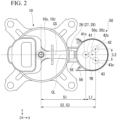
- Fig. 2 is a plan view of the compressor 2 of the embodiment.
- Fig. 3 is a cross-sectional view along line F3-F3 of Fig. 1 .
- Fig. 3 illustrates a cross section of a portion in which the three suction pipes 41, 42, and 43 penetrate the bottom portion of the case 51 of the accumulator 50.
- a first center 41c of a first flow path cross section 41s of the first suction pipe 41, a second center 42c of a second flow path cross section 42s of the second suction pipe 42, and a third center 43c of a third flow path cross section 43s of the third suction pipe 43 are defined as illustrated in Fig. 3 .
- the first center 41c, the second center 42c, and the third center 43c are positioned at vertices of a triangle TR as viewed from the +Z direction.
- the three suction pipes 41, 42, and 43 are disposed close to each other compared to a case in which three suction pipes 41, 42, and 43 are disposed to be aligned in a line as viewed from the +Z direction. Therefore, the accumulator 50 is made compact.
- the triangle TR is an equilateral triangle. All interior angles of the triangle TR are less than 90 degrees (acute angles).
- the three suction pipes 41, 42, and 43 are disposed close to each other compared to a case in which one interior angle of the triangle TR is 90 degrees or more (an obtuse angle). Therefore, the accumulator 50 is made compact.
- components for an accumulator having two suction pipes can be used for components of the accumulator 50.
- the compressor main body 10 vibrates in accordance with eccentric rotation of the eccentric part 32 and the roller 33.
- a distance between a center 10c of the compressor main body 10 and a center 50c of the accumulator 50 decreases as illustrated in Fig. 2 .
- vibrations of the accumulator 50 according to the vibrations of the compressor main body 10 are suppressed.
- a first distance S1 in the X direction between the first center 41c and the center 10c of the compressor main body 10, a second distance S2 in the X direction between the second center 42c and the center 10c of the compressor main body 10, and a third distance S3 in the X direction between the third center 43c and the center 10c of the compressor main body 10 are defined as illustrated in Fig. 2 .
- the first distance S1 is smaller than the second distance S2 and the third distance S3.
- the first suction pipe 41 is disposed closer to the compressor main body 10 than the second suction pipe 42 and the third suction pipe 43 are.
- the second distance S2 and the third distance S3 are equal.
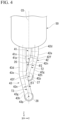
- Fig. 4 is a side view of external suction pipes as viewed from an F4 direction of Fig. 1 .
- the three suction ports 26, 27, and 28 described above are disposed in the +Z direction, that is, disposed to overlap a reference plane CS to be described later as viewed from above the accumulator 50.
- the three suction ports 26, 27, and 28 are disposed at the same position as viewed from the +Z direction.
- the three suction ports 26, 27, and 28 open in the same +X direction.
- the three suction pipes 41, 42, and 43 are connected from the same +X direction with respect to the three suction ports 26, 27, and 28. Therefore, connection work of the three suction pipes 41, 42, and 43 is simplified.
- a lower end portion (end portion in the -Z direction and the -X direction) of the first suction pipe 41 is connected to the first suction port 26 positioned uppermost in the +Z direction among the three suction ports 26, 27, and 28.
- a lower end portion of the third suction pipe 43 is connected to the third suction port 28 positioned lowermost in the -Z direction.
- a lower end portion of the second suction pipe 42 is connected to the second suction port 27 positioned in the middle between the first suction port 26 and the third suction port 28 in the Z direction.
- the three suction pipes 41, 42, and 43 include internal suction pipes 41b, 42b, and 43b, external suction pipes 41a, 42a, and 43a, and end suction pipes 41k, 42k, and 43k, respectively.
- the internal suction pipes 41b, 42b, and 43b are disposed inside the case 51.
- the external suction pipes 41a, 42a, and 43a are disposed outside the case 51.
- the internal suction pipes 41b, 42b, and 43b and the external suction pipes 41a, 42a, and 43a are connected in the vicinity of the bottom portion of the case 51.
- the external suction pipes 41a, 42a, and 43a are in contact with air, the external suction pipes 41a, 42a, and 43a are formed of a copper material or the like having corrosion resistance. Since the internal suction pipes 41b, 42b, and 43b are not in contact with air, the internal suction pipes 41b, 42b, and 43b are formed of a low-cost steel material or the like. Further, the internal suction pipes 41b, 42b, and 43b and the external suction pipes 41a, 42a, and 43a may be integrally formed of the same material.
- the internal suction pipes 41b, 42b, and 43b each have a linear central axis.
- the central axes of the internal suction pipes 41b, 42b, and 43b are parallel to the Z direction and are disposed parallel to the central axis of the case 51 of the accumulator 50.
- Upper end portions (end portions in the +Z direction) of the internal suction pipes 41b, 42b, and 43b open inside the case 51.
- Outflow holes 49 of a lubricating oil are formed in lower portions of the internal suction pipes 41b, 42b, and 43b. The lubricating oil accumulated in the lower portion of the case 51 flows out of the outflow holes 49 little by little to the internal suction pipes 41b, 42b, and 43b.
- the end suction pipes 41k, 42k, and 43k are formed in a straight pipe shape. Central axes of the end suction pipes 41k, 42k, and 43k have a linear shape and are disposed parallel to the X direction. End portions of the end suction pipes 41k, 42k, and 43k in the +X direction are disposed on inner sides of the three suction ports 26, 27, and 28 of the compressor main body 10. End portions of the end suction pipes 41k, 42k, and 43k in the -X direction are disposed on inner sides of the three suction holes 38 of the cylinder 35.
- the end suction pipes 41k, 42k, and 43k are connected to the three suction ports 26, 27, and 28 by brazing or the like on an outer side of the compressor main body 10.
- a first opening center 41p is defined as an opening center on a lower end side (end portion in the -Z direction and -X direction) of the first suction pipe 41.
- the first opening center 41p is an opening center of the end suction pipe 41k in the -X direction.
- a second opening center 42p is defined as an opening center on a lower end side of the second suction pipe 42.
- a third opening center 43p is defined as an opening center on a lower end side of the third suction pipe 43.
- the first opening center 41p, the second opening center 42p, and the third opening center 43p are included in the reference plane CS to be described later.
- Fig. 5 is an enlarged view of a surrounding portion of the external suction pipe of Fig. 1 .
- the external suction pipe 41a of the first suction pipe 41 includes an upper straight pipe part 41d, a main curved pipe part 41g, and a lower straight pipe part 41h.
- the upper straight pipe part 41d is disposed at an upper end portion (end portion in the +Z direction) of the external suction pipe 41a.
- the upper straight pipe part 41d is disposed at a portion penetrating the bottom portion of the accumulator 50.
- a central axis 41n of the upper straight pipe part 41d is linear and is disposed parallel to the Z direction.
- the lower straight pipe part 41h is disposed at a lower end portion (end portion in the -Z direction and -X direction) of the external suction pipe 41a.
- the lower straight pipe part 41h is disposed at a connection portion between it and the end suction pipe 41k.
- the central axis 41n of the lower straight pipe part 41h is linear and is disposed parallel to the X direction.
- the main curved pipe part 41g is disposed between the upper straight pipe part 41d and the lower straight pipe part 41h.
- the main curved pipe part 41g is curved from below the accumulator 50 toward the first suction port 26.
- the central axis 41n of the main curved pipe part 41g is a curve that is curved in the -X direction toward the -Z direction. As illustrated in Fig. 4 , the central axis 41n of the main curved pipe part 41g is disposed in a plane parallel to an XZ plane.
- the reference plane (first virtual plane) CS is defined as a virtual plane including the central axis 41n of the main curved pipe part 41g.
- the entire central axis 41n of the first suction pipe 41 is included in the reference plane CS.
- the entire portion including the main curved pipe part 41g of the first suction pipe 41 overlaps the reference plane CS.
- the three suction ports 26, 27, and 28 of the compressor main body 10 overlap the reference plane CS as viewed from the +Z direction (from above the accumulator 50).
- the external suction pipe 42a of the second suction pipe 42 includes an upper straight pipe part 42d, a sub-curved pipe part 42e, an intermediate straight pipe part 42f, a main curved pipe part 42g, and a lower straight pipe part 42h.
- the upper straight pipe part 42d of the second suction pipe 42 is formed in the same manner as the upper straight pipe part 41d of the first suction pipe 41.
- the lower straight pipe part 42h of the second suction pipe 42 is formed in the same manner as the lower straight pipe part 41h of the first suction pipe 41.
- the sub-curved pipe part 42e is disposed in the -Z direction of the upper straight pipe part 42d.
- the sub-curved pipe part 42e is curved from an end portion of the upper straight pipe part 42d in the -Z direction toward the reference plane CS.
- a central axis 42n of the sub-curved pipe part 42e is a curve that is curved in the -Y direction toward the -Z direction. As illustrated in Fig. 5 , the central axis 42n of the sub-curved pipe part 42e is disposed in a plane parallel to a YZ plane.
- the intermediate straight pipe part 42f is disposed in the -Z direction of the sub-curved pipe part 42e.
- the intermediate straight pipe part 42f extends in the -Z direction and the -Y direction from an end portion of the sub-curved pipe part 42e in the -Z direction.
- the central axis 42n of the intermediate straight pipe part 42f is linear.
- the central axis 42n of the intermediate straight pipe part 42f is disposed in a plane parallel to the YZ plane.
- the intermediate straight pipe part 42f is disposed between the sub-curved pipe part 42e and the main curved pipe part 42g. That is, the sub-curved pipe part 42e is disposed between the upper straight pipe part 42d and the intermediate straight pipe part 42f.
- the main curved pipe part 42g is disposed between the intermediate straight pipe part 42f and the lower straight pipe part 42h. Therefore, starting points of both end portions of the sub-curved pipe part 42e and the main curved pipe part 42g become clear.
- the sub-curved pipe part 42e is formed with an end portion of the upper straight pipe part 42d in the -Z direction and an end portion of the intermediate straight pipe part 42f in the +Z direction as references.
- the main curved pipe part 42g is formed with an end portion of the intermediate straight pipe part 42f in the -Z direction and an end portion of the lower straight pipe part 42h in the +X direction as references. Therefore, the sub-curved pipe part 42e and the main curved pipe part 42g are formed with high accuracy at a low cost.
- the main curved pipe part 42g is disposed in the -Z direction of the intermediate straight pipe part 42f.
- the main curved pipe part 42g is curved from below the accumulator 50 toward the second suction port 27.
- the central axis 42n of the main curved pipe part 42g is a curve that is curved in the -X direction toward the -Z direction. As illustrated in Fig. 4 , the main curved pipe part 42g extends in the -Z direction and the -Y direction from an end portion of the intermediate straight pipe part 42f in the -Z direction.
- the central axis 42n of the main curved pipe part 42g is disposed in a plane parallel to the X direction.
- a second virtual plane T2 is defined as a virtual plane including the central axis 42n of the main curved pipe part 42g.
- the second virtual plane T2 is inclined with respect to the reference plane CS.
- the external suction pipe 43a of the third suction pipe 43 includes an upper straight pipe part 43d, a sub-curved pipe part 43e, an intermediate straight pipe part 43f, a main curved pipe part 43g, and a lower straight pipe part 43h.
- the upper straight pipe part 43d of the third suction pipe 43 is formed in the same manner as the upper straight pipe part 41d of the first suction pipe 41.
- the lower straight pipe part 43h of the third suction pipe 43 is formed in the same manner as the lower straight pipe part 41h of the first suction pipe 41.
- the sub-curved pipe part 43e is disposed in the -Z direction of the upper straight pipe part 43d.
- the sub-curved pipe part 43e is curved from an end portion of the upper straight pipe part 43d in the -Z direction toward the reference plane CS.
- a central axis 43n of the sub-curved pipe part 43e is a curve that is curved in the +Y direction toward the -Z direction.
- the central axis 43n of the sub-curved pipe part 43e is disposed in a plane parallel to the YZ plane.
- the intermediate straight pipe part 43f is disposed in the -Z direction of the sub-curved pipe part 43e.
- the intermediate straight pipe part 43f extends in the -Z direction and the +Y direction from an end portion of the sub-curved pipe part 43e in the -Z direction.
- the central axis 43n of the intermediate straight pipe part 43f is linear.
- the central axis 43n of the intermediate straight pipe part 43f is disposed in a plane parallel to the YZ plane.
- the intermediate straight pipe part 43f is disposed between the sub-curved pipe part 43e and the main curved pipe part 43g. Thereby, the sub-curved pipe part 43e and the main curved pipe part 43g are easily formed with high accuracy.
- the main curved pipe part 43g is disposed in the -Z direction of the intermediate straight pipe part 43f.
- the main curved pipe part 43g is curved from below the accumulator 50 toward the third suction port 28.
- the central axis 43n of the main curved pipe part 43g is a curve that is curved in the -X direction toward the -Z direction.
- the main curved pipe part 43g extends in the -Z direction and the +Y direction from an end portion of the intermediate straight pipe part 43f in the -Z direction.
- the central axis 43n of the main curved pipe part 43g is disposed in a plane parallel to the X direction.
- a third virtual plane T3 is defined as a plane including the central axis 43n of the main curved pipe part 43g.
- the third virtual plane T3 is inclined with respect to the reference plane CS.
- the second virtual plane T2 and the third virtual plane T3 are inclined to opposite sides from each other with respect to the reference plane CS.
- the second virtual plane T2 intersects the reference plane CS at the second opening center 42p.
- the second virtual plane T2 extends in the +Z direction and the +Y direction from the second opening center 42p.
- the third virtual plane T3 intersects the reference plane CS at the third opening center 43p.
- the third virtual plane T3 extends in the +Z direction and the -Y direction from the third opening center 43p.
- the second suction pipe 42 and the third suction pipe 43 are disposed on opposite sides from each other with respect to the reference plane CS on which the first suction pipe 41 is disposed. Therefore, the three suction pipes 41, 42, and 43 are efficiently laid out. Thereby, even when the second suction pipe 42 and the third suction pipe 43 are disposed close to each other to be made compact, interference between the three suction pipes 41, 42, and 43 is avoided. Also, even when flow path cross-sectional areas of the three suction pipes 41, 42, and 43 are expanded to reduce suction loss, interference between the three suction pipes 41, 42, and 43 is avoided. Also, a difference between a length of the second suction pipe 42 and a length of the third suction pipe 43 is reduced, and the suction loss is averaged.
- An inclination angle of the second virtual plane T2 with respect to the reference plane CS is ⁇ 2.
- An inclination angle of the third virtual plane T3 with respect to the reference plane CS is ⁇ 3.
- the three suction pipes 41, 42, and 43 are efficiently laid out.
- ⁇ 2 ⁇ ⁇ 3 is established.
- the main curved pipe part 43g of the third suction pipe 43 becomes more distant from the main curved pipe part 42g of the second suction pipe 42 in the -Z direction. Therefore, interference between the main curved pipe part 43g of the third suction pipe 43 and the main curved pipe part 42g of the second suction pipe 42 is avoided.
- a distance from a straight line connecting the second center 42c and the third center 43c to the first center 41c is L1.
- a distance between the second center 42c and the third center 43c is L2.
- L1 ⁇ L2 is established.
- L2 is increased, interference between the second suction pipe 42 and the third suction pipe 43 is avoided.
- interference between the main curved pipe part 42g of the second suction pipe 42 and the main curved pipe part 43g of the third suction pipe 43 is avoided.
- L1 is reduced, the three suction pipes 41, 42, and 43 are disposed close to each other, and the accumulator 50 is made compact.
- first suction pipe 41 is disposed closest to the compressor main body 10 in the X direction.
- the first suction pipe 41 is disposed between the second suction pipe 42 and the third suction pipe 43 in the Y direction.
- the first suction pipe 41 is connected to the first suction port 26 in the most +Z direction. Therefore, even when L1 is small, interference of the second suction pipe 42 and the third suction pipe 43 with the first suction pipe 41 is avoided.
- a distance in the Z direction between the first opening center 41p and the second opening center 42p is P1.
- a distance in the Z direction between the second opening center 42p and the third opening center 43p is P2.
- P1 ⁇ P2 is established.
- P2 is increased, interference between the second suction pipe 42 and the third suction pipe 43 is avoided.
- interference between the main curved pipe part 42g of the second suction pipe 42 and the main curved pipe part 43g of the third suction pipe 43 is avoided.
- P1 is reduced, the compressor main body 10 is made compact in the Z direction. Further, the first suction pipe 41 is disposed closest to the compressor main body 10 in the X direction.
- the first suction pipe 41 is disposed between the second suction pipe 42 and the third suction pipe 43 in the Y direction. In the Z direction, the first suction pipe 41 is connected to the first suction port 26 in the most +Z direction. Therefore, even when P1 is small, interference of the second suction pipe 42 and the third suction pipe 43 with the first suction pipe 41 is avoided.
- L2 ⁇ P1 is established between L2 illustrated in Fig. 2 and P1 illustrated in Fig. 5 .
- a high-pressure refrigerant after compression is sealed inside the case 11 of the compressor main body 10.
- P1 is increased, an intermediate portion between the first suction port 26 and the second suction port 27 becomes longer, and a cross-sectional area of the case 11 in the portion becomes larger. Therefore, pressure resistance of the case 11 is improved.
- L2 is reduced, the three suction pipes 41, 42, and 43 are disposed close to each other, and the accumulator 50 is made compact. Further, a low-pressure refrigerant before compression is sealed inside the accumulator 50. Therefore, even when an intermediate portion between the second suction pipe 42 and the third suction pipe 43 is short, pressure resistance of the accumulator 50 is secured.
- the compressor 2 of the embodiment includes the three suction pipes 41, 42, and 43.
- the three suction pipes 41, 42, and 43 includes the main curved pipe parts 41g, 42g, and 43g that are curved from below the accumulator 50 toward the three suction ports 26, 27, and 28.
- the second virtual plane T2 and the third virtual plane T3 are inclined to opposite sides from each other with respect to the reference plane CS.
- the reference plane CS is a plane on which the central axis 41n of the main curved pipe part 41g of the first suction pipe 41 is disposed.
- the second virtual plane T2 is a plane on which the central axis 42n of the main curved pipe part 42g of the second suction pipe 42 is disposed.
- the third virtual plane T3 is a plane on which the central axis 43n of the main curved pipe part 43g of the third suction pipe 43 is disposed.
- the three suction pipes 41, 42, and 43 are efficiently laid out. Even when the second suction pipe 42 and the third suction pipe 43 are disposed close to each other to be made compact, interference between the three suction pipes 41, 42, and 43 is avoided. Even when flow path cross-sectional areas of the three suction pipes 41, 42, and 43 are expanded to reduce a suction loss, interference between the three suction pipes 41, 42, and 43 is avoided. Therefore, the compressor 2 is made compact.
- the second suction pipe 42 and the third suction pipe 43 include the upper straight pipe parts 42d and 43d, the lower straight pipe parts 42h and 43h, the sub-curved pipe parts 42e and 43e, and the intermediate straight pipe parts 42f and 43f.
- the upper straight pipe parts 42d and 43d penetrate the bottom portion of the accumulator 50.
- the lower straight pipe parts 42h and 43h are connected to the suction ports 27 and 28 of the case 11.
- the sub-curved pipe parts 42e and 43e are curved from the lower ends of the upper straight pipe parts 42d and 43d toward the reference plane CS.
- the intermediate straight pipe parts 42f and 43f are disposed between the sub-curved pipe parts 42e and 43e and the main curved pipe parts 42g and 43g.
- a distance from the straight line connecting the second center 42c and the third center 43c to the first center 41c is L1.
- a distance between the second center 42c and the third center 43c is L2.
- L1 ⁇ L2 is established.
- a distance in the Z direction between the first opening center 41p at the lower end portion (end portion in the -Z direction and -X direction) of the first suction pipe 41 and the second opening center 42p at the lower end portion of the second suction pipe 42 is P1.
- a distance in the Z direction between the second opening center 42p at the lower end portion of the second suction pipe 42 and the third opening center 43p at the lower end portion of the third suction pipe 43 is P2.
- the three suction ports 26, 27, and 28 are disposed to overlap the reference plane CS as viewed from above the accumulator 50.
- the three suction pipes 41, 42, and 43 are connected to the three suction ports 26, 27, and 28 from the same direction. Therefore, connection work of the three suction pipes 41, 42, and 43 is simplified.
- the refrigeration cycle device 1 of an embodiment includes the compressor 2, the radiator 3, the expansion device 4, and the heat absorber 5 described above.
- the radiator 3 is connected to the compressor 2.
- the expansion device 4 is connected to the radiator 3.
- the heat absorber 5 is connected to the expansion device 4.
- the compressor 2 described above is made compact. Therefore, the compact refrigeration cycle device 1 is provided.
- the reference plane CS of the embodiment is defined as a virtual plane including the central axis 41n of the main curved pipe part 41g.
- the reference plane CS may also be defined as a plane including a central axis 10z of the compressor main body 10 and the first opening center 41p (see Fig. 5 ) as illustrated in Fig. 2 .
- a center connection line CL is defined as a straight line passing through the center 10c of the compressor main body 10 and the center 50c of the accumulator 50.
- the reference plane CS may also be defined as the XZ plane including the center connection line CL.
- the reference plane CS may also be defined as a plane including the central axis 10z of the compressor main body 10 and a central axis 50z of the accumulator 50.
- the first suction pipe 41 is disposed to satisfy the following. As illustrated in Fig. 3 , the first flow path cross section 41s of the first suction pipe 41 overlaps the center connection line CL as viewed from the +Z direction. In other words, the first flow path cross section 41s of the first suction pipe 41 intersects the reference plane CS. At least a part of the first flow path cross section 41s may overlap the center connection line CL.
- the second suction pipe 42 and the third suction pipe 43 are disposed to satisfy the following.
- the second flow path cross section 42s of the second suction pipe 42 and the third flow path cross section 43s of the third suction pipe 43 are disposed on opposite sides of the center connection line CL (or the reference plane CS) sandwiched therebetween.
- the second flow path cross section 42s is positioned in the +Y direction of the center connection line CL
- the third flow path cross section 43s is positioned in the -Y direction of the center connection line CL.
- a second separation distance from the second flow path cross section 42s to the center connection line CL and a third separation distance from the third flow path cross section 43s to the center connection line CL may be different.
- the second separation distance and the third separation distance are the same.
- the triangle TR is line-symmetric with respect to the center connection line CL.
- the first suction pipe 41 of the embodiment has the following configuration.
- the first suction pipe 41 is disposed closer to the compressor main body 10 than the second suction pipe 42 and the third suction pipe 43 are.
- the first flow path cross section 41s of the first suction pipe 41 overlaps the center connection line CL.
- the first suction pipe 41 is connected to the first suction port 26 which is positioned uppermost among the three suction ports 26, 27, and 28.
- the first suction port 26 overlaps the center connection line CL.
- the first suction pipe 41 has a simple shape that is curved only two-dimensionally. Therefore, material costs and processing costs of the first suction pipe 41 are suppressed.
- the second suction pipe 42 and the third suction pipe 43 of the embodiment have the following configurations.
- the second suction pipe 42 and the third suction pipe 43 are disposed farther from the compressor main body 10 than the first suction pipe 41 is.
- the second flow path cross section 42s of the second suction pipe 42 and the third flow path cross section 43s of the third suction pipe 43 are positioned on opposite sides of the center connection line CL sandwiched therebetween.
- the third suction pipe 43 is connected to the third suction port 28 of the third compression mechanism unit 23 positioned lowermost.
- the second suction pipe 42 is connected to the second suction port 27 of the second compression mechanism unit 22 positioned in the middle in the Z direction. When viewed from the +Z direction, the second suction port 27 and the third suction port 28 overlap the center connection line CL.
- the second suction pipe 42 and the third suction pipe 43 have a three-dimensionally curved shape. Even in this case, since the second suction pipe 42 and the third suction pipe 43 are disposed far from the compressor main body 10, curved shapes thereof are gently and smoothly realized. Also, since the second suction pipe 42 and the third suction pipe 43 are positioned on opposite sides of the center connection line CL sandwiched therebetween, lengths thereof are not unnecessarily large. Therefore, material costs and processing costs of the second suction pipe 42 and the third suction pipe 43 are suppressed.
- the compressor 2 of the embodiment is a so-called rotary-type compressor.
- the compressor 2 may be a compressor of another type.
- the second virtual plane T2 and the third virtual plane T3 are inclined to opposite sides from each other with respect to the reference plane CS. Thereby, the compressor 2 can be made compact.
Landscapes
- Engineering & Computer Science (AREA)
- Mechanical Engineering (AREA)
- General Engineering & Computer Science (AREA)
- Physics & Mathematics (AREA)
- Thermal Sciences (AREA)
- Chemical & Material Sciences (AREA)
- Analytical Chemistry (AREA)
- Power Engineering (AREA)
- Applications Or Details Of Rotary Compressors (AREA)
- Compressor (AREA)
Description
- Embodiments of the present invention relate to a compressor and a refrigeration cycle device.
- A refrigeration cycle device includes a compressor which compresses a gaseous refrigerant. The compressor includes a compressor main body and an accumulator. The accumulator performs gas-liquid separation of a refrigerant and supplies a gaseous refrigerant to the compressor main body.
- Compressors are required to be made compact.
- [Patent Document 1]
Japanese Unexamined Patent Application, First Publication No. 2016-48032
WO 2005/124/156 A1 discloses a compressor comprising: - a compressor main body which houses a plurality of compression mechanism units and an electric motor unit driving the plurality of compression mechanism units in a case;
- an accumulator supported by the compressor main body and including a refrigerant introduction part at an upper portion thereof; and
- three suction pipes penetrating a bottom portion of the accumulator, having one end sides which open inside the accumulator, and having the other end sides connected to three suction ports provided in the case, wherein
- the three suction pipes are a first suction pipe, a second suction pipe, and a third suction pipe,
- the three suction pipes are disposed at a portion penetrating the bottom portion of the accumulator so that a first center of a first flow path cross section of the first suction pipe, a second center of a second flow path cross section of the second suction pipe, and a third center of a third flow path cross section of the third suction pipe are positioned at vertices of a triangle as viewed from above the accumulator,
- the first suction pipe is disposed so that a first distance between the first center and a center of the compressor main body is smaller than a second distance between the second center and the center of the compressor main body and a third distance between the third center and the center of the compressor main body,
- the other end side of the first suction pipe is connected to a first suction port which is positioned uppermost among the three suction ports, and
- the three suction pipes include main curved pipe parts which are curved from below the accumulator toward the three suction ports.
- A problem to be solved by the present invention is to provide a compressor and a refrigeration cycle device which can be made compact.
- A compressor of the embodiment includes a compressor main body, an accumulator, and three suction pipes. The compressor main body houses a plurality of compression mechanism units and an electric motor unit driving the plurality of compression mechanism units in a case. The accumulator is supported by the compressor main body and includes a refrigerant introduction part at an upper portion thereof. The three suction pipes penetrate a bottom portion of the accumulator, have one end sides which open inside the accumulator, and have the other end sides connected to three suction ports provided in the case. The three suction pipes are a first suction pipe, a second suction pipe, and a third suction pipe. The three suction pipes are disposed so that a first center, a second center, and a third center are positioned at vertices of a triangle as viewed from above the accumulator. The first center is a center of a first flow path cross section of the first suction pipe at a portion penetrating the bottom portion of the accumulator. The second center is a center of a second flow path cross section of the second suction pipe. The third center is a center of a third flow path cross section of the third suction pipe. The first suction pipe is disposed so that a first distance is smaller than a second distance and a third distance. The first distance is a distance between the first center and a center of the compressor main body. The second distance is a distance between the second center and the center of the compressor main body. The third distance is a distance between the third center and the center of the compressor main body. The other end side of the first suction pipe is connected to a first suction port which is positioned uppermost among the three suction ports. The three suction pipes include main curved pipe parts which are curved from below the accumulator toward the three suction ports. A second virtual plane and a third virtual plane are inclined to opposite sides from each other with respect to a first virtual plane. The first virtual plane is a plane on which a central axis of the main curved pipe part of the first suction pipe is disposed. The second virtual plane is a plane on which a central axis of the main curved pipe part of the second suction pipe is disposed. The third virtual plane is a plane on which a central axis of the main curved pipe part of the third suction pipe is disposed. The other end side of the third suction pipe is connected to a third suction port which is positioned lowermost among the three suction ports. θ2 < θ3 is established when an inclination angle of the second virtual plane with respect to the first virtual plane is θ2 and an inclination angle of the third virtual plane with respect to the first virtual plane is θ3.
-
-
Fig. 1 is a schematic configuration view of a refrigeration cycle device of an embodiment including a cross-sectional view of a compressor. -
Fig. 2 is a plan view of the compressor of the embodiment. -
Fig. 3 is a cross-sectional view along line F3-F3 ofFig. 1 . -
Fig. 4 is a side view of external suction pipes as viewed from an F4 direction ofFig. 1 . -
Fig. 5 is an enlarged view of a surrounding portion of the external suction pipes ofFig. 1 . - Hereinafter, a
compressor 2 and a refrigeration cycle device 1 of embodiments will be described with reference to the drawings. - In the present application, an X direction, a Y direction, and a Z direction of an orthogonal coordinate system will be defined as follows. The X direction is a direction in which a compressor
main body 10 and anaccumulator 50 are aligned, and a +X direction is a direction from the compressormain body 10 toward theaccumulator 50. The Z direction is a direction parallel to a central axis of the compressormain body 10, and a +Z direction is a direction from a compression mechanism unit 20 to anelectric motor unit 15. The Y direction is a direction perpendicular to the X direction and the Z direction. For example, the X direction and Y direction are horizontal directions. For example, the Z direction is a vertical direction, and the +Z direction is vertically upward. - The refrigeration cycle device 1 will be briefly described.
-
Fig. 1 is a schematic configuration view of the refrigeration cycle device 1 of an embodiment including a cross-sectional view of thecompressor 2. - As illustrated in
Fig. 1 , the refrigeration cycle device 1 includes acompressor 2, a radiator (for example, a condenser) 3 connected to thecompressor 2, an expansion device (for example, an expansion valve) 4 connected to theradiator 3, and a heat absorber (for example, an evaporator) 5 connected to theexpansion device 4. The refrigeration cycle device 1 contains a refrigerant such as R410A, R32, or carbon dioxide (CO2). The refrigerant circulates in the refrigeration cycle device 1 while changing its phase. - The
compressor 2 is a so-called rotary-type compressor. Therotary compressor 2, for example, compresses a low-pressure gaseous refrigerant (fluid) taken into the inside to obtain a high-temperature and high-pressure gaseous refrigerant. Further, a specific configuration of thecompressor 2 will be described later. - The
radiator 3 radiates heat from the high-temperature and high-pressure gaseous refrigerant discharged from thecompressor 2. - The
expansion device 4 reduces a pressure of the high-pressure refrigerant sent from theradiator 3 to convert the high-pressure refrigerant into a low-temperature and low-pressure liquid refrigerant. - The
heat absorber 5 evaporates the low-temperature and low-pressure liquid refrigerant sent from theexpansion device 4 to convert the low-temperature and low-pressure liquid refrigerant into a low-pressure gaseous refrigerant. In theheat absorber 5, evaporation of the low-pressure liquid refrigerant takes evaporation heat from the surroundings, and thus the surroundings are cooled. Further, the low-pressure gaseous refrigerant that has passed through theheat absorber 5 is taken into thecompressor 2 described above. - As described above, in the refrigeration cycle device 1 of the present embodiment, a refrigerant serving as a working fluid circulates while changing its phase between a gaseous refrigerant and a liquid refrigerant, and heating, cooling, or the like is performed by utilizing such heat radiation and heat absorption.
- The
compressor 2 of the embodiment will be described. - The
compressor 2 includes the compressormain body 10 and theaccumulator 50. - The compressor
main body 10 includes ashaft 13, theelectric motor unit 15 that rotates theshaft 13, a plurality of compression mechanism units 20 that compress a gaseous refrigerant due to rotation of theshaft 13, and acylindrical case 11 that houses theshaft 13, theelectric motor unit 15, and the compression mechanism units 20. - The
shaft 13 is disposed along the central axis of the compressormain body 10. - The
electric motor unit 15 is disposed in the +Z direction of theshaft 13. Theelectric motor unit 15 includes astator 15a and arotor 15b. Thestator 15a is fixed to an inner circumferential surface of thecase 11. Therotor 15b is fixed to an outer circumferential surface of theshaft 13. Theelectric motor unit 15 rotates theshaft 13 inside thecase 11. - The
case 11 is formed in a cylindrical shape with both end portions closed. Thecase 11 includes adischarge part 19 at an upper end portion. Thedischarge part 19 is formed by a pipe and is disposed along a central axis of thecase 11. Thedischarge part 19 has a discharge port at an upper end portion. Thedischarge part 19 discharges the gaseous refrigerant inside thecase 11 from the discharge port. - The plurality of compression mechanism units 20 are disposed in a -Z direction of the
shaft 13. The plurality of compression mechanism units 20 include three compression mechanism units 20 including, for example, a first compression mechanism unit 21, a second compression mechanism unit 22, and a third compression mechanism unit 23. The first compression mechanism unit 21, the second compression mechanism unit 22, and the third compression mechanism unit 23 are disposed to be aligned in that order from the +Z direction to the -Z direction. The first compression mechanism unit 21 is positioned uppermost in the +Z direction among the plurality of compression mechanism units 20. Hereinafter, a configuration of the first compression mechanism unit 21 will be described as a representative. Configurations of the second compression mechanism unit 22 and the third compression mechanism unit 23 are the same as those of the first compression mechanism unit 21 except for a direction of eccentricity of aneccentric part 32. - The first compression mechanism unit 21 includes the
eccentric part 32, aroller 33, acylinder 35, abearing 17, and apartition plate 25. - The
eccentric part 32 is formed integrally with theshaft 13 in a columnar shape. When viewed from the +Z direction, a center of theeccentric part 32 is eccentric from a central axis of theshaft 13. - The
roller 33 is formed in a cylindrical shape and is disposed along an outer circumference of theeccentric part 32. - The
cylinder 35 is fixed to aframe 20a. An outer circumferential surface of theframe 20a is fixed to an inner circumferential surface of thecase 11. Thecylinder 35 includes acylinder chamber 36, a vane (not illustrated), and asuction hole 38. Thecylinder chamber 36 houses theeccentric part 32 and theroller 33 inside. The vane is housed in a vane groove formed in thecylinder 35 and can advance into and retreat from the inside of thecylinder chamber 36. The vane is biased such that a distal end portion thereof is brought into contact with an outer circumferential surface of theroller 33.
The vane, together with theeccentric part 32 and theroller 33, partitions the inside of thecylinder chamber 36 into a suction chamber and a compression chamber. Thesuction hole 38 is formed from an outer circumferential surface of thecylinder 35 to thecylinder chamber 36. Thesuction hole 38 introduces the gaseous refrigerant into the suction chamber of thecylinder chamber 36. Afirst suction port 26 is provided in thecase 11 to face thesuction hole 38. Similarly, asecond suction port 27 is provided to face thesuction hole 38 of the second compression mechanism unit 22, and athird suction port 28 is provided to face thesuction hole 38 of the third compression mechanism unit 23. The threesuction ports case 11. - The
bearing 17 and thepartition plate 25 are disposed on both sides of thecylinder 35 in the Z direction and close both end portions of thecylinder chamber 36 in the Z direction. Thebearing 17 and thepartition plate 25 have a discharge hole for discharging the gaseous refrigerant compressed in the compression chamber of thecylinder chamber 36 to the inside of thecase 11. - An operation of the first compression mechanism unit 21 will be described.
- When the
electric motor unit 15 rotates theshaft 13, theeccentric part 32 and theroller 33 rotate eccentrically inside thecylinder chamber 36. When theroller 33 rotates eccentrically, the gaseous refrigerant is suctioned into the suction chamber of thecylinder chamber 36, and the gaseous refrigerant in the compression chamber is compressed. The compressed gaseous refrigerant is discharged from the discharge hole of thebearing 17 and thepartition plate 25 to the inside of thecase 11. The gaseous refrigerant inside thecase 11 is discharged from thedischarge part 19 to the outside of thecase 11. - The
accumulator 50 will be described. - The
accumulator 50 includes acase 51, astrainer plate 60, and a plurality ofsuction pipes 40, and separates an introduced refrigerant into a gaseous refrigerant and a liquid refrigerant. The liquid refrigerant is stored in a bottom portion of thecase 51, and the gaseous refrigerant is supplied to the compressormain body 10 through the plurality ofsuction pipes 40. - The
case 51 is formed in a cylindrical shape with both end portions closed. Thecase 51 is formed by connecting afirst case 51a in the +Z direction and asecond case 51b in the -Z direction. Throughholes 58 through which the plurality ofsuction pipes 40 pass are formed in the bottom portion of thecase 51. Thecase 51 is supported by the compressormain body 10 via abracket 55 and a belt 56 (seeFig. 2 ). - The
case 51 includes arefrigerant introduction part 59 and aretainer 52. - The
introduction part 59 is provided at an upper end portion of thecase 51. Theintroduction part 59 is formed by a pipe and is disposed along a central axis of thecase 51. - The
retainer 52 is formed in a ring shape, and an outer circumferential surface thereof is fixed to an inner circumferential surface of thecase 51. - The
strainer plate 60 is disposed inside thecase 51 in the +Z direction, and captures foreign substances contained in the refrigerant introduced from theintroduction part 59. - The plurality of
suction pipes 40 will be described in detail. - The plurality of
suction pipes 40 are three suction pipes including afirst suction pipe 41, asecond suction pipe 42, and athird suction pipe 43. The threesuction pipes holes 58 formed in the bottom portion of thecase 51. End portions (one end sides) of the threesuction pipes case 51. End portions (the other end sides) of the threesuction pipes suction ports main body 10. -
Fig. 2 is a plan view of thecompressor 2 of the embodiment.Fig. 3 is a cross-sectional view along line F3-F3 ofFig. 1 .Fig. 3 illustrates a cross section of a portion in which the threesuction pipes case 51 of theaccumulator 50. Afirst center 41c of a first flow path cross section 41s of thefirst suction pipe 41, asecond center 42c of a second flow pathcross section 42s of thesecond suction pipe 42, and athird center 43c of a third flow pathcross section 43s of thethird suction pipe 43 are defined as illustrated inFig. 3 . Thefirst center 41c, thesecond center 42c, and thethird center 43c are positioned at vertices of a triangle TR as viewed from the +Z direction. Thereby, the threesuction pipes suction pipes accumulator 50 is made compact. In the example ofFig. 3 , the triangle TR is an equilateral triangle. All interior angles of the triangle TR are less than 90 degrees (acute angles). Thereby, the threesuction pipes accumulator 50 is made compact. - When the
accumulator 50 is made compact, components for an accumulator having two suction pipes can be used for components of theaccumulator 50. - The compressor
main body 10 vibrates in accordance with eccentric rotation of theeccentric part 32 and theroller 33. When theaccumulator 50 is made compact, a distance between a center 10c of the compressormain body 10 and acenter 50c of theaccumulator 50 decreases as illustrated inFig. 2 . Thereby, vibrations of theaccumulator 50 according to the vibrations of the compressormain body 10 are suppressed. - A first distance S1 in the X direction between the
first center 41c and thecenter 10c of the compressormain body 10, a second distance S2 in the X direction between thesecond center 42c and thecenter 10c of the compressormain body 10, and a third distance S3 in the X direction between thethird center 43c and thecenter 10c of the compressormain body 10 are defined as illustrated inFig. 2 . The first distance S1 is smaller than the second distance S2 and the third distance S3. In other words, thefirst suction pipe 41 is disposed closer to the compressormain body 10 than thesecond suction pipe 42 and thethird suction pipe 43 are. In the example ofFig. 2 , the second distance S2 and the third distance S3 are equal. -
Fig. 4 is a side view of external suction pipes as viewed from an F4 direction ofFig. 1 . The threesuction ports accumulator 50. The threesuction ports suction ports suction pipes suction ports suction pipes - A lower end portion (end portion in the -Z direction and the -X direction) of the
first suction pipe 41 is connected to thefirst suction port 26 positioned uppermost in the +Z direction among the threesuction ports third suction pipe 43 is connected to thethird suction port 28 positioned lowermost in the -Z direction. A lower end portion of thesecond suction pipe 42 is connected to thesecond suction port 27 positioned in the middle between thefirst suction port 26 and thethird suction port 28 in the Z direction. - As illustrated in
Fig. 1 , the threesuction pipes suction pipes case 51. The external suction pipes 41a, 42a, and 43a are disposed outside thecase 51. The internal suction pipes 41b, 42b, and 43b and the external suction pipes 41a, 42a, and 43a are connected in the vicinity of the bottom portion of thecase 51. Since the external suction pipes 41a, 42a, and 43a are in contact with air, the external suction pipes 41a, 42a, and 43a are formed of a copper material or the like having corrosion resistance. Since the internal suction pipes 41b, 42b, and 43b are not in contact with air, the internal suction pipes 41b, 42b, and 43b are formed of a low-cost steel material or the like. Further, the internal suction pipes 41b, 42b, and 43b and the external suction pipes 41a, 42a, and 43a may be integrally formed of the same material. - The internal suction pipes 41b, 42b, and 43b each have a linear central axis. The central axes of the internal suction pipes 41b, 42b, and 43b are parallel to the Z direction and are disposed parallel to the central axis of the
case 51 of theaccumulator 50. Upper end portions (end portions in the +Z direction) of the internal suction pipes 41b, 42b, and 43b open inside thecase 51. Outflow holes 49 of a lubricating oil are formed in lower portions of the internal suction pipes 41b, 42b, and 43b. The lubricating oil accumulated in the lower portion of thecase 51 flows out of the outflow holes 49 little by little to the internal suction pipes 41b, 42b, and 43b. - The
end suction pipes end suction pipes end suction pipes suction ports main body 10. End portions of theend suction pipes suction holes 38 of thecylinder 35. Theend suction pipes suction ports main body 10. Lower end portions of the external suction pipes 41a, 42a, and 43a are inserted into the inside of theend suction pipes suction pipes suction holes 38 of thecylinder 35. The external suction pipes 41a, 42a, and 43a and theend suction pipes - A
first opening center 41p is defined as an opening center on a lower end side (end portion in the -Z direction and -X direction) of thefirst suction pipe 41. Specifically, thefirst opening center 41p is an opening center of theend suction pipe 41k in the -X direction. Similarly, asecond opening center 42p is defined as an opening center on a lower end side of thesecond suction pipe 42. Athird opening center 43p is defined as an opening center on a lower end side of thethird suction pipe 43. Thefirst opening center 41p, thesecond opening center 42p, and thethird opening center 43p are included in the reference plane CS to be described later. - The external suction pipes 41a, 42a, and 43a will be described in detail.
-
Fig. 5 is an enlarged view of a surrounding portion of the external suction pipe ofFig. 1 . The external suction pipe 41a of thefirst suction pipe 41 includes an upperstraight pipe part 41d, a maincurved pipe part 41g, and a lowerstraight pipe part 41h. - The upper
straight pipe part 41d is disposed at an upper end portion (end portion in the +Z direction) of the external suction pipe 41a. The upperstraight pipe part 41d is disposed at a portion penetrating the bottom portion of theaccumulator 50. Acentral axis 41n of the upperstraight pipe part 41d is linear and is disposed parallel to the Z direction. - The lower
straight pipe part 41h is disposed at a lower end portion (end portion in the -Z direction and -X direction) of the external suction pipe 41a. The lowerstraight pipe part 41h is disposed at a connection portion between it and theend suction pipe 41k. Thecentral axis 41n of the lowerstraight pipe part 41h is linear and is disposed parallel to the X direction. - The main
curved pipe part 41g is disposed between the upperstraight pipe part 41d and the lowerstraight pipe part 41h. The maincurved pipe part 41g is curved from below theaccumulator 50 toward thefirst suction port 26. Thecentral axis 41n of the maincurved pipe part 41g is a curve that is curved in the -X direction toward the -Z direction. As illustrated inFig. 4 , thecentral axis 41n of the maincurved pipe part 41g is disposed in a plane parallel to an XZ plane. The reference plane (first virtual plane) CS is defined as a virtual plane including thecentral axis 41n of the maincurved pipe part 41g. The entirecentral axis 41n of thefirst suction pipe 41 is included in the reference plane CS. When viewed from the +Z direction and the +X direction, the entire portion including the maincurved pipe part 41g of thefirst suction pipe 41 overlaps the reference plane CS. The threesuction ports main body 10 overlap the reference plane CS as viewed from the +Z direction (from above the accumulator 50). - The external suction pipe 42a of the
second suction pipe 42 includes an upperstraight pipe part 42d, asub-curved pipe part 42e, an intermediatestraight pipe part 42f, a maincurved pipe part 42g, and a lowerstraight pipe part 42h. The upperstraight pipe part 42d of thesecond suction pipe 42 is formed in the same manner as the upperstraight pipe part 41d of thefirst suction pipe 41. The lowerstraight pipe part 42h of thesecond suction pipe 42 is formed in the same manner as the lowerstraight pipe part 41h of thefirst suction pipe 41. - The
sub-curved pipe part 42e is disposed in the -Z direction of the upperstraight pipe part 42d. Thesub-curved pipe part 42e is curved from an end portion of the upperstraight pipe part 42d in the -Z direction toward the reference plane CS. Acentral axis 42n of thesub-curved pipe part 42e is a curve that is curved in the -Y direction toward the -Z direction. As illustrated inFig. 5 , thecentral axis 42n of thesub-curved pipe part 42e is disposed in a plane parallel to a YZ plane. - As illustrated in
Fig. 4 , the intermediatestraight pipe part 42f is disposed in the -Z direction of thesub-curved pipe part 42e. The intermediatestraight pipe part 42f extends in the -Z direction and the -Y direction from an end portion of thesub-curved pipe part 42e in the -Z direction. Thecentral axis 42n of the intermediatestraight pipe part 42f is linear. As illustrated inFig. 5 , thecentral axis 42n of the intermediatestraight pipe part 42f is disposed in a plane parallel to the YZ plane. - The intermediate
straight pipe part 42f is disposed between thesub-curved pipe part 42e and the maincurved pipe part 42g. That is, thesub-curved pipe part 42e is disposed between the upperstraight pipe part 42d and the intermediatestraight pipe part 42f. The maincurved pipe part 42g is disposed between the intermediatestraight pipe part 42f and the lowerstraight pipe part 42h. Therefore, starting points of both end portions of thesub-curved pipe part 42e and the maincurved pipe part 42g become clear. Thesub-curved pipe part 42e is formed with an end portion of the upperstraight pipe part 42d in the -Z direction and an end portion of the intermediatestraight pipe part 42f in the +Z direction as references. The maincurved pipe part 42g is formed with an end portion of the intermediatestraight pipe part 42f in the -Z direction and an end portion of the lowerstraight pipe part 42h in the +X direction as references. Therefore, thesub-curved pipe part 42e and the maincurved pipe part 42g are formed with high accuracy at a low cost. - The main
curved pipe part 42g is disposed in the -Z direction of the intermediatestraight pipe part 42f. The maincurved pipe part 42g is curved from below theaccumulator 50 toward thesecond suction port 27. Thecentral axis 42n of the maincurved pipe part 42g is a curve that is curved in the -X direction toward the -Z direction. As illustrated inFig. 4 , the maincurved pipe part 42g extends in the -Z direction and the -Y direction from an end portion of the intermediatestraight pipe part 42f in the -Z direction. Thecentral axis 42n of the maincurved pipe part 42g is disposed in a plane parallel to the X direction. A second virtual plane T2 is defined as a virtual plane including thecentral axis 42n of the maincurved pipe part 42g. The second virtual plane T2 is inclined with respect to the reference plane CS. - The external suction pipe 43a of the
third suction pipe 43 includes an upperstraight pipe part 43d, asub-curved pipe part 43e, an intermediatestraight pipe part 43f, a maincurved pipe part 43g, and a lowerstraight pipe part 43h. The upperstraight pipe part 43d of thethird suction pipe 43 is formed in the same manner as the upperstraight pipe part 41d of thefirst suction pipe 41. The lowerstraight pipe part 43h of thethird suction pipe 43 is formed in the same manner as the lowerstraight pipe part 41h of thefirst suction pipe 41. - The
sub-curved pipe part 43e is disposed in the -Z direction of the upperstraight pipe part 43d. Thesub-curved pipe part 43e is curved from an end portion of the upperstraight pipe part 43d in the -Z direction toward the reference plane CS. Acentral axis 43n of thesub-curved pipe part 43e is a curve that is curved in the +Y direction toward the -Z direction. Thecentral axis 43n of thesub-curved pipe part 43e is disposed in a plane parallel to the YZ plane. - The intermediate
straight pipe part 43f is disposed in the -Z direction of thesub-curved pipe part 43e. The intermediatestraight pipe part 43f extends in the -Z direction and the +Y direction from an end portion of thesub-curved pipe part 43e in the -Z direction. Thecentral axis 43n of the intermediatestraight pipe part 43f is linear. Thecentral axis 43n of the intermediatestraight pipe part 43f is disposed in a plane parallel to the YZ plane. - The intermediate
straight pipe part 43f is disposed between thesub-curved pipe part 43e and the maincurved pipe part 43g. Thereby, thesub-curved pipe part 43e and the maincurved pipe part 43g are easily formed with high accuracy. - The main
curved pipe part 43g is disposed in the -Z direction of the intermediatestraight pipe part 43f. The maincurved pipe part 43g is curved from below theaccumulator 50 toward thethird suction port 28. Thecentral axis 43n of the maincurved pipe part 43g is a curve that is curved in the -X direction toward the -Z direction. The maincurved pipe part 43g extends in the -Z direction and the +Y direction from an end portion of the intermediatestraight pipe part 43f in the -Z direction. Thecentral axis 43n of the maincurved pipe part 43g is disposed in a plane parallel to the X direction. A third virtual plane T3 is defined as a plane including thecentral axis 43n of the maincurved pipe part 43g. The third virtual plane T3 is inclined with respect to the reference plane CS. - As illustrated in
Fig. 4 , the second virtual plane T2 and the third virtual plane T3 are inclined to opposite sides from each other with respect to the reference plane CS. The second virtual plane T2 intersects the reference plane CS at thesecond opening center 42p. The second virtual plane T2 extends in the +Z direction and the +Y direction from thesecond opening center 42p. The third virtual plane T3 intersects the reference plane CS at thethird opening center 43p. The third virtual plane T3 extends in the +Z direction and the -Y direction from thethird opening center 43p. - Thereby, the
second suction pipe 42 and thethird suction pipe 43 are disposed on opposite sides from each other with respect to the reference plane CS on which thefirst suction pipe 41 is disposed. Therefore, the threesuction pipes second suction pipe 42 and thethird suction pipe 43 are disposed close to each other to be made compact, interference between the threesuction pipes suction pipes suction pipes second suction pipe 42 and a length of thethird suction pipe 43 is reduced, and the suction loss is averaged. - An inclination angle of the second virtual plane T2 with respect to the reference plane CS is θ2. An inclination angle of the third virtual plane T3 with respect to the reference plane CS is θ3. At this time, θ2 = θ3 is established. Thereby, the three
suction pipes curved pipe part 43g of thethird suction pipe 43 becomes more distant from the maincurved pipe part 42g of thesecond suction pipe 42 in the -Z direction. Therefore, interference between the maincurved pipe part 43g of thethird suction pipe 43 and the maincurved pipe part 42g of thesecond suction pipe 42 is avoided. - As illustrated in
Fig. 2 , a distance from a straight line connecting thesecond center 42c and thethird center 43c to thefirst center 41c is L1. A distance between thesecond center 42c and thethird center 43c is L2. At this time, L1 < L2 is established. When L2 is increased, interference between thesecond suction pipe 42 and thethird suction pipe 43 is avoided. Particularly, interference between the maincurved pipe part 42g of thesecond suction pipe 42 and the maincurved pipe part 43g of thethird suction pipe 43 is avoided. On the other hand, when L1 is reduced, the threesuction pipes accumulator 50 is made compact. Further, thefirst suction pipe 41 is disposed closest to the compressormain body 10 in the X direction. Thefirst suction pipe 41 is disposed between thesecond suction pipe 42 and thethird suction pipe 43 in the Y direction. In the Z direction, thefirst suction pipe 41 is connected to thefirst suction port 26 in the most +Z direction. Therefore, even when L1 is small, interference of thesecond suction pipe 42 and thethird suction pipe 43 with thefirst suction pipe 41 is avoided. - As illustrated in
Fig. 5 , a distance in the Z direction between thefirst opening center 41p and thesecond opening center 42p is P1. A distance in the Z direction between thesecond opening center 42p and thethird opening center 43p is P2. At this time, P1 < P2 is established. When P2 is increased, interference between thesecond suction pipe 42 and thethird suction pipe 43 is avoided. Particularly, interference between the maincurved pipe part 42g of thesecond suction pipe 42 and the maincurved pipe part 43g of thethird suction pipe 43 is avoided. On the other hand, when P1 is reduced, the compressormain body 10 is made compact in the Z direction. Further, thefirst suction pipe 41 is disposed closest to the compressormain body 10 in the X direction. Thefirst suction pipe 41 is disposed between thesecond suction pipe 42 and thethird suction pipe 43 in the Y direction. In the Z direction, thefirst suction pipe 41 is connected to thefirst suction port 26 in the most +Z direction. Therefore, even when P1 is small, interference of thesecond suction pipe 42 and thethird suction pipe 43 with thefirst suction pipe 41 is avoided. - L2 < P1 is established between L2 illustrated in
Fig. 2 and P1 illustrated inFig. 5 . A high-pressure refrigerant after compression is sealed inside thecase 11 of the compressormain body 10. When P1 is increased, an intermediate portion between thefirst suction port 26 and thesecond suction port 27 becomes longer, and a cross-sectional area of thecase 11 in the portion becomes larger. Therefore, pressure resistance of thecase 11 is improved. When L2 is reduced, the threesuction pipes accumulator 50 is made compact. Further, a low-pressure refrigerant before compression is sealed inside theaccumulator 50. Therefore, even when an intermediate portion between thesecond suction pipe 42 and thethird suction pipe 43 is short, pressure resistance of theaccumulator 50 is secured. - As described in detail above, the
compressor 2 of the embodiment includes the threesuction pipes suction pipes curved pipe parts accumulator 50 toward the threesuction ports central axis 41n of the maincurved pipe part 41g of thefirst suction pipe 41 is disposed. The second virtual plane T2 is a plane on which thecentral axis 42n of the maincurved pipe part 42g of thesecond suction pipe 42 is disposed. The third virtual plane T3 is a plane on which thecentral axis 43n of the maincurved pipe part 43g of thethird suction pipe 43 is disposed. - Thereby, the three
suction pipes second suction pipe 42 and thethird suction pipe 43 are disposed close to each other to be made compact, interference between the threesuction pipes suction pipes suction pipes compressor 2 is made compact. - The
second suction pipe 42 and thethird suction pipe 43 include the upperstraight pipe parts straight pipe parts sub-curved pipe parts straight pipe parts straight pipe parts accumulator 50. The lowerstraight pipe parts suction ports case 11. Thesub-curved pipe parts straight pipe parts straight pipe parts sub-curved pipe parts curved pipe parts - Thereby, starting points of both end portions of the
sub-curved pipe part 42e and the maincurved pipe part 42g become clear. Therefore, thesub-curved pipe part 42e and the maincurved pipe part 42g are formed with high accuracy at a low cost. - A distance from the straight line connecting the
second center 42c and thethird center 43c to thefirst center 41c is L1. A distance between thesecond center 42c and thethird center 43c is L2. At this time, L1 < L2 is established. - When L2 is increased, interference between the
second suction pipe 42 and thethird suction pipe 43 is avoided. When L1 is reduced, the threesuction pipes suction pipes accumulator 50 is made compact. - A distance in the Z direction between the
first opening center 41p at the lower end portion (end portion in the -Z direction and -X direction) of thefirst suction pipe 41 and thesecond opening center 42p at the lower end portion of thesecond suction pipe 42 is P1. A distance in the Z direction between thesecond opening center 42p at the lower end portion of thesecond suction pipe 42 and thethird opening center 43p at the lower end portion of thethird suction pipe 43 is P2. At this time, L2 < P1 < P2 is established. - When P2 is increased, interference between the
second suction pipe 42 and thethird suction pipe 43 is avoided. When P1 is reduced, the compressormain body 10 is made compact in the Z direction while avoiding interference between the threesuction pipes case 11 is improved. When L2 is reduced, the threesuction pipes accumulator 50. Therefore, theaccumulator 50 is made compact. - The three
suction ports accumulator 50. - Thereby, the three
suction pipes suction ports suction pipes - The refrigeration cycle device 1 of an embodiment includes the
compressor 2, theradiator 3, theexpansion device 4, and theheat absorber 5 described above. Theradiator 3 is connected to thecompressor 2. Theexpansion device 4 is connected to theradiator 3. Theheat absorber 5 is connected to theexpansion device 4. - The
compressor 2 described above is made compact. Therefore, the compact refrigeration cycle device 1 is provided. - The reference plane CS of the embodiment is defined as a virtual plane including the
central axis 41n of the maincurved pipe part 41g. On the other hand, the reference plane CS may also be defined as a plane including acentral axis 10z of the compressormain body 10 and thefirst opening center 41p (seeFig. 5 ) as illustrated inFig. 2 . A center connection line CL is defined as a straight line passing through thecenter 10c of the compressormain body 10 and thecenter 50c of theaccumulator 50. The reference plane CS may also be defined as the XZ plane including the center connection line CL. In other words, the reference plane CS may also be defined as a plane including thecentral axis 10z of the compressormain body 10 and acentral axis 50z of theaccumulator 50. - The
first suction pipe 41 is disposed to satisfy the following. As illustrated inFig. 3 , the first flow path cross section 41s of thefirst suction pipe 41 overlaps the center connection line CL as viewed from the +Z direction. In other words, the first flow path cross section 41s of thefirst suction pipe 41 intersects the reference plane CS. At least a part of the first flow path cross section 41s may overlap the center connection line CL. - The
second suction pipe 42 and thethird suction pipe 43 are disposed to satisfy the following. As illustrated inFig. 3 , as viewed from the +Z direction, the second flow pathcross section 42s of thesecond suction pipe 42 and the third flow pathcross section 43s of thethird suction pipe 43 are disposed on opposite sides of the center connection line CL (or the reference plane CS) sandwiched therebetween. In the example ofFig. 3 , the second flow pathcross section 42s is positioned in the +Y direction of the center connection line CL, and the third flow pathcross section 43s is positioned in the -Y direction of the center connection line CL. A second separation distance from the second flow pathcross section 42s to the center connection line CL and a third separation distance from the third flow pathcross section 43s to the center connection line CL may be different. In the example ofFig. 3 , the second separation distance and the third separation distance are the same. In the example ofFig. 3 , the triangle TR is line-symmetric with respect to the center connection line CL. - The
first suction pipe 41 of the embodiment has the following configuration. Thefirst suction pipe 41 is disposed closer to the compressormain body 10 than thesecond suction pipe 42 and thethird suction pipe 43 are. When viewed from the +Z direction, the first flow path cross section 41s of thefirst suction pipe 41 overlaps the center connection line CL. Thefirst suction pipe 41 is connected to thefirst suction port 26 which is positioned uppermost among the threesuction ports first suction port 26 overlaps the center connection line CL. - Thereby, a length of the
first suction pipe 41 decreases. Therefore, heat loss of a gaseous refrigerant flowing through thefirst suction pipe 41 decreases, and thus efficiency of thecompressor 2 is improved. Also, as illustrated inFig. 1 , thefirst suction pipe 41 has a simple shape that is curved only two-dimensionally. Therefore, material costs and processing costs of thefirst suction pipe 41 are suppressed. - The
second suction pipe 42 and thethird suction pipe 43 of the embodiment have the following configurations. Thesecond suction pipe 42 and thethird suction pipe 43 are disposed farther from the compressormain body 10 than thefirst suction pipe 41 is. When viewed from the +Z direction, the second flow pathcross section 42s of thesecond suction pipe 42 and the third flow pathcross section 43s of thethird suction pipe 43 are positioned on opposite sides of the center connection line CL sandwiched therebetween. Thethird suction pipe 43 is connected to thethird suction port 28 of the third compression mechanism unit 23 positioned lowermost. Thesecond suction pipe 42 is connected to thesecond suction port 27 of the second compression mechanism unit 22 positioned in the middle in the Z direction. When viewed from the +Z direction, thesecond suction port 27 and thethird suction port 28 overlap the center connection line CL. - Thereby, as illustrated in
Fig. 4 , thesecond suction pipe 42 and thethird suction pipe 43 have a three-dimensionally curved shape. Even in this case, since thesecond suction pipe 42 and thethird suction pipe 43 are disposed far from the compressormain body 10, curved shapes thereof are gently and smoothly realized. Also, since thesecond suction pipe 42 and thethird suction pipe 43 are positioned on opposite sides of the center connection line CL sandwiched therebetween, lengths thereof are not unnecessarily large. Therefore, material costs and processing costs of thesecond suction pipe 42 and thethird suction pipe 43 are suppressed. - The
compressor 2 of the embodiment is a so-called rotary-type compressor. On the other hand, thecompressor 2 may be a compressor of another type. - According to at least one embodiment described above, the second virtual plane T2 and the third virtual plane T3 are inclined to opposite sides from each other with respect to the reference plane CS. Thereby, the
compressor 2 can be made compact. -
- CS Reference plane (first virtual plane)
- S 1 First distance
- S2 Second distance
- S3 Third distance
- TR Triangle
- T2 Second virtual plane
- T3 Third virtual plane
- 1 Refrigeration cycle device
- 2 Compressor
- 3 Radiator
- 4 Expansion device
- 5 Heat absorber
- 10 Compressor main body
- 10c Center
- 11 Case
- 15 Electric motor unit
- 21 First compression mechanism unit
- 22 Second compression mechanism unit
- 23 Third compression mechanism unit
- 26 First suction port
- 27 Second suction port
- 28 Third suction port
- 41 First suction pipe
- 41c First center
- 41g Main curved pipe part
- 41n Central axis
- 41p First opening center
- 41s First flow path cross section
- 42 Second suction pipe
- 42c Second center
- 42d Upper straight pipe part
- 42e Sub-curved pipe part
- 42f Intermediate straight pipe part
- 42g Main curved pipe part
- 42h Lower straight pipe part
- 42n Central axis
- 42p Second opening center
- 42s Second flow path cross section
- 43 Third suction pipe
- 43c Third center
- 43d Upper straight pipe part
- 43e Sub-curved pipe part
- 43f Intermediate straight pipe part
- 43g Main curved pipe part
- 43h Lower straight pipe part
- 43n Central axis
- 43p Third opening center
- 43s Third flow path cross section
- 50 Accumulator
- 59 Introduction part
Claims (6)
- A compressor (2) comprising:a compressor main body (10) which houses a plurality of compression mechanism units (21, 22, 23) and an electric motor unit (15) driving the plurality of compression mechanism units (21, 22, 23) in a case;an accumulator (50) supported by the compressor main body (10) and including a refrigerant introduction part (59) at an upper portion thereof; andthree suction pipes (41, 42, 43) penetrating a bottom portion of the accumulator (50), having one end sides which open inside the accumulator (50), and having the other end sides connected to three suction ports (26, 27, 28) provided in the case, whereinthe three suction pipes (41, 42, 43) are a first suction pipe (41), a second suction pipe (42), and a third suction pipe (43),the three suction pipes (41, 42, 43) are disposed at a portion penetrating the bottom portion of the accumulator (50) so that a first center (41c) of a first flow path cross section (41s) of the first suction pipe (41), a second center (42c) of a second flow path cross section (42s) of the second suction pipe (42), and a third center (43c) of a third flow path cross section (43s) of the third suction pipe (43) are positioned at vertices of a triangle as viewed from above the accumulator (50),the first suction pipe (41) is disposed so that a first distance (S 1) between the first center (41c) and a center (10c) of the compressor main body (10) is smaller than a second distance (S2) between the second center (42c) and the center (10c) of the compressor main body (10) and a third distance (S3) between the third center (43c) and the center (10c) of the compressor main body (10),the other end side of the first suction pipe (41) is connected to a first suction port (26) which is positioned uppermost among the three suction ports (26, 27, 28),the three suction pipes (41, 42, 43) include main curved pipe parts (41g, 42g, 43g) which are curved from below the accumulator (50) toward the three suction ports (26, 27, 28),characterized in thata second virtual plane (T2) on which a central axis (42n) of the main curved pipe part (42g) of the second suction pipe (42) is disposed and a third virtual plane (T3) on which a central axis (43n) of the main curved pipe part (43g) of the third suction pipe (43) is disposed are inclined to opposite sides from each other with respect to a first virtual plane (CS) on which a central axis (41n) of the main curved pipe part (41g) of the first suction pipe (41) is disposed,the other end side of the third suction pipe (43) is connected to a third suction port (28) which is positioned lowermost among the three suction ports (26, 27, 28), and θ2 < θ3 is established when an inclination angle of the second virtual plane (T2) with respect to the first virtual plane (CS) is θ2 and an inclination angle of the third virtual plane (T3) with respect to the first virtual plane (CS) is θ3.
- The compressor (2) according to claim 1, characterized in that the second suction pipe (42) and the third suction pipe (43) each include:an upper straight pipe part (42d, 43d) penetrating the bottom portion of the accumulator (50);a lower straight pipe part (42h, 43h) connected to the suction port of the case (51);a sub-curved pipe part (42e, 43e) curved from a lower end of the upper straight pipe part (42d, 43d) toward the first virtual plane (CS); andan intermediate straight pipe part (42f, 43f) disposed between the sub-curved pipe part (42e, 43e) and the main curved pipe part (42g, 43g).
- The compressor (2) according to claim 1 or 2, characterized in that, when a distance from a straight line connecting the second center (42c) and the third center (43c) to the first center (41c) is L1 and a distance between the second center (42c) and the third center (43c) is L2, L1 < L2 is established.
- The compressor (2) according to claim 3, characterized in that, when a distance between a first opening center (41p) on the other end side of the first suction pipe (41) and a second opening center (42p) on the other end side of the second suction pipe (42) along a central axis of the compressor main body (10) is P1 and a distance between the second opening center (42p) on the other end side of the second suction pipe (42) and a third opening center (43p) on the other end side of the third suction pipe (43) along the central axis of the compressor main body (10) is P2, L2 < P1 < P2 is established.
- The compressor (2) according to any one of claims 1 to 4, characterized in that the three suction ports (26, 27, 28) are disposed to overlap the first virtual plane (CS) as viewed from above the accumulator (50).
- A refrigeration cycle device (1) comprising:the compressor (2) according to any one of claims 1 to 5;a radiator (3) connected to the compressor (2);an expansion device (4) connected to the radiator (3); anda heat absorber (5) connected to the expansion device (4).
Applications Claiming Priority (1)
| Application Number | Priority Date | Filing Date | Title |
|---|---|---|---|
| PCT/JP2019/002635 WO2020157786A1 (en) | 2019-01-28 | 2019-01-28 | Compressor and refrigeration cycle device |
Publications (3)
| Publication Number | Publication Date |
|---|---|
| EP3919745A1 EP3919745A1 (en) | 2021-12-08 |
| EP3919745A4 EP3919745A4 (en) | 2022-07-27 |
| EP3919745B1 true EP3919745B1 (en) | 2024-05-29 |
Family
ID=71841432
Family Applications (1)
| Application Number | Title | Priority Date | Filing Date |
|---|---|---|---|
| EP19913571.6A Active EP3919745B1 (en) | 2019-01-28 | 2019-01-28 | Compressor and refrigeration cycle device |
Country Status (5)
| Country | Link |
|---|---|
| US (1) | US11971201B2 (en) |
| EP (1) | EP3919745B1 (en) |
| JP (1) | JP7223778B2 (en) |
| CN (1) | CN113302400B (en) |
| WO (1) | WO2020157786A1 (en) |
Families Citing this family (3)
| Publication number | Priority date | Publication date | Assignee | Title |
|---|---|---|---|---|
| CN114183360B (en) * | 2021-12-17 | 2023-03-28 | 珠海格力电器股份有限公司 | Rotor compressor liquid storage device, rotor compressor assembly and air conditioner |
| CN116951826A (en) * | 2022-04-15 | 2023-10-27 | 广东美的制冷设备有限公司 | Compressors and air conditioners |
| CN119022521B (en) * | 2024-10-23 | 2025-02-25 | 珠海凌达压缩机有限公司 | Intake pipe structure, liquid distributor and compressor |
Family Cites Families (7)
| Publication number | Priority date | Publication date | Assignee | Title |
|---|---|---|---|---|
| JP4594302B2 (en) | 2004-06-15 | 2010-12-08 | 東芝キヤリア株式会社 | Multi-cylinder rotary compressor |
| JP4877054B2 (en) * | 2007-04-27 | 2012-02-15 | 株式会社富士通ゼネラル | Rotary compressor |
| JP5070097B2 (en) * | 2007-08-28 | 2012-11-07 | 東芝キヤリア株式会社 | Two-cylinder rotary compressor and refrigeration cycle apparatus using the same |
| JP2010059859A (en) * | 2008-09-03 | 2010-03-18 | Fujitsu General Ltd | Injectible two-stage compression rotary compressor |
| JP6080646B2 (en) * | 2013-03-27 | 2017-02-15 | 三菱電機株式会社 | Rotary compressor |
| JP6275848B2 (en) * | 2014-07-25 | 2018-02-07 | 東芝キヤリア株式会社 | Compressor and refrigeration cycle apparatus |
| JP6262101B2 (en) | 2014-08-27 | 2018-01-17 | 東芝キヤリア株式会社 | Rotary compressor and refrigeration cycle apparatus |
-
2019
- 2019-01-28 WO PCT/JP2019/002635 patent/WO2020157786A1/en not_active Ceased
- 2019-01-28 CN CN201980088169.8A patent/CN113302400B/en active Active
- 2019-01-28 JP JP2020568879A patent/JP7223778B2/en active Active
- 2019-01-28 EP EP19913571.6A patent/EP3919745B1/en active Active
-
2021
- 2021-07-14 US US17/305,736 patent/US11971201B2/en active Active
Also Published As
| Publication number | Publication date |
|---|---|
| EP3919745A1 (en) | 2021-12-08 |
| EP3919745A4 (en) | 2022-07-27 |
| CN113302400B (en) | 2023-08-25 |
| CN113302400A (en) | 2021-08-24 |
| JPWO2020157786A1 (en) | 2021-10-28 |
| US11971201B2 (en) | 2024-04-30 |
| JP7223778B2 (en) | 2023-02-16 |
| WO2020157786A1 (en) | 2020-08-06 |
| US20210341188A1 (en) | 2021-11-04 |
Similar Documents
| Publication | Publication Date | Title |
|---|---|---|
| US11339999B2 (en) | Compressor and accumulator with multiple suction tubes for a refrigeration cycle device | |
| US7914267B2 (en) | Multistage compressor for a CO2 cycle that includes a rotary compressing mechanism and a scroll compressing mechanism | |
| US11971201B2 (en) | Compressor and refrigeration cycle device | |
| EP2894340B1 (en) | Rotary compressor | |
| US20180080447A1 (en) | Electric compressor | |
| EP3575605A1 (en) | Hermetic compressor | |
| US9951774B2 (en) | Lubrication of a rotary compressor | |
| EP3754270B1 (en) | Accumulator, and compressor for air conditioning | |
| CN104819154B (en) | hermetic compressor | |
| US12025130B2 (en) | Rotary compressor and refrigeration cycle apparatus | |
| US12006934B2 (en) | Scroll compressor and refrigeration cycle apparatus | |
| JP2005146986A (en) | Heat exchanger integral type compressor with built-in accumulator | |
| CN111954761B (en) | Rotary compressor and refrigeration cycle device | |
| KR20180090324A (en) | Rotary compressor | |
| CN114555948B (en) | Compressors and Refrigeration Cycle Units | |
| EP4459128B1 (en) | Rotary compressor and refrigeration apparatus | |
| CN116792311B (en) | Multistage rotary compressor and refrigeration cycle unit | |
| CN111120320B (en) | Swing rotor type expansion compressor | |
| JP2017025885A (en) | Rotary compressor and refrigeration cycle apparatus | |
| JP7170547B2 (en) | Rotary compressor and refrigeration cycle equipment | |
| KR200382915Y1 (en) | Accumulator connection structure of rotary compressor | |
| JP2024157942A (en) | Positive displacement compressor and refrigerator | |
| CN120530265A (en) | Rotary compressor and refrigeration device | |
| WO2019111350A1 (en) | Compressor and refrigeration cycle device |
Legal Events
| Date | Code | Title | Description |
|---|---|---|---|
| STAA | Information on the status of an ep patent application or granted ep patent |
Free format text: STATUS: THE INTERNATIONAL PUBLICATION HAS BEEN MADE |
|
| PUAI | Public reference made under article 153(3) epc to a published international application that has entered the european phase |
Free format text: ORIGINAL CODE: 0009012 |
|
| STAA | Information on the status of an ep patent application or granted ep patent |
Free format text: STATUS: REQUEST FOR EXAMINATION WAS MADE |
|
| 17P | Request for examination filed |
Effective date: 20210723 |
|
| AK | Designated contracting states |
Kind code of ref document: A1 Designated state(s): AL AT BE BG CH CY CZ DE DK EE ES FI FR GB GR HR HU IE IS IT LI LT LU LV MC MK MT NL NO PL PT RO RS SE SI SK SM TR |
|
| DAV | Request for validation of the european patent (deleted) | ||
| DAX | Request for extension of the european patent (deleted) | ||
| A4 | Supplementary search report drawn up and despatched |
Effective date: 20220629 |
|
| RIC1 | Information provided on ipc code assigned before grant |
Ipc: F25B 43/00 20060101ALI20220623BHEP Ipc: F25B 1/10 20060101ALI20220623BHEP Ipc: F04C 18/356 20060101ALI20220623BHEP Ipc: F04C 29/12 20060101ALI20220623BHEP Ipc: F04C 23/00 20060101AFI20220623BHEP |
|
| GRAP | Despatch of communication of intention to grant a patent |
Free format text: ORIGINAL CODE: EPIDOSNIGR1 |
|
| STAA | Information on the status of an ep patent application or granted ep patent |
Free format text: STATUS: GRANT OF PATENT IS INTENDED |
|
| INTG | Intention to grant announced |
Effective date: 20231221 |
|
| GRAS | Grant fee paid |
Free format text: ORIGINAL CODE: EPIDOSNIGR3 |
|
| GRAA | (expected) grant |
Free format text: ORIGINAL CODE: 0009210 |
|
| STAA | Information on the status of an ep patent application or granted ep patent |
Free format text: STATUS: THE PATENT HAS BEEN GRANTED |
|
| AK | Designated contracting states |
Kind code of ref document: B1 Designated state(s): AL AT BE BG CH CY CZ DE DK EE ES FI FR GB GR HR HU IE IS IT LI LT LU LV MC MK MT NL NO PL PT RO RS SE SI SK SM TR |
|
| REG | Reference to a national code |
Ref country code: CH Ref legal event code: EP |
|
| REG | Reference to a national code |
Ref country code: IE Ref legal event code: FG4D |
|
| REG | Reference to a national code |
Ref country code: DE Ref legal event code: R096 Ref document number: 602019053097 Country of ref document: DE |
|
| REG | Reference to a national code |
Ref country code: LT Ref legal event code: MG9D |
|
| REG | Reference to a national code |
Ref country code: NL Ref legal event code: MP Effective date: 20240529 |
|
| PG25 | Lapsed in a contracting state [announced via postgrant information from national office to epo] |
Ref country code: IS Free format text: LAPSE BECAUSE OF FAILURE TO SUBMIT A TRANSLATION OF THE DESCRIPTION OR TO PAY THE FEE WITHIN THE PRESCRIBED TIME-LIMIT Effective date: 20240929 |
|
| PG25 | Lapsed in a contracting state [announced via postgrant information from national office to epo] |
Ref country code: BG Free format text: LAPSE BECAUSE OF FAILURE TO SUBMIT A TRANSLATION OF THE DESCRIPTION OR TO PAY THE FEE WITHIN THE PRESCRIBED TIME-LIMIT Effective date: 20240529 |
|
| PG25 | Lapsed in a contracting state [announced via postgrant information from national office to epo] |
Ref country code: HR Free format text: LAPSE BECAUSE OF FAILURE TO SUBMIT A TRANSLATION OF THE DESCRIPTION OR TO PAY THE FEE WITHIN THE PRESCRIBED TIME-LIMIT Effective date: 20240529 Ref country code: FI Free format text: LAPSE BECAUSE OF FAILURE TO SUBMIT A TRANSLATION OF THE DESCRIPTION OR TO PAY THE FEE WITHIN THE PRESCRIBED TIME-LIMIT Effective date: 20240529 |
|
| PG25 | Lapsed in a contracting state [announced via postgrant information from national office to epo] |
Ref country code: GR Free format text: LAPSE BECAUSE OF FAILURE TO SUBMIT A TRANSLATION OF THE DESCRIPTION OR TO PAY THE FEE WITHIN THE PRESCRIBED TIME-LIMIT Effective date: 20240830 |
|
| REG | Reference to a national code |
Ref country code: AT Ref legal event code: MK05 Ref document number: 1690864 Country of ref document: AT Kind code of ref document: T Effective date: 20240529 |
|
| PG25 | Lapsed in a contracting state [announced via postgrant information from national office to epo] |
Ref country code: ES Free format text: LAPSE BECAUSE OF FAILURE TO SUBMIT A TRANSLATION OF THE DESCRIPTION OR TO PAY THE FEE WITHIN THE PRESCRIBED TIME-LIMIT Effective date: 20240529 |
|
| PG25 | Lapsed in a contracting state [announced via postgrant information from national office to epo] |
Ref country code: AT Free format text: LAPSE BECAUSE OF FAILURE TO SUBMIT A TRANSLATION OF THE DESCRIPTION OR TO PAY THE FEE WITHIN THE PRESCRIBED TIME-LIMIT Effective date: 20240529 |
|
| PG25 | Lapsed in a contracting state [announced via postgrant information from national office to epo] |
Ref country code: PL Free format text: LAPSE BECAUSE OF FAILURE TO SUBMIT A TRANSLATION OF THE DESCRIPTION OR TO PAY THE FEE WITHIN THE PRESCRIBED TIME-LIMIT Effective date: 20240529 |
|
| PG25 | Lapsed in a contracting state [announced via postgrant information from national office to epo] |
Ref country code: LV Free format text: LAPSE BECAUSE OF FAILURE TO SUBMIT A TRANSLATION OF THE DESCRIPTION OR TO PAY THE FEE WITHIN THE PRESCRIBED TIME-LIMIT Effective date: 20240529 |
|
| PG25 | Lapsed in a contracting state [announced via postgrant information from national office to epo] |
Ref country code: PL Free format text: LAPSE BECAUSE OF FAILURE TO SUBMIT A TRANSLATION OF THE DESCRIPTION OR TO PAY THE FEE WITHIN THE PRESCRIBED TIME-LIMIT Effective date: 20240529 Ref country code: NO Free format text: LAPSE BECAUSE OF FAILURE TO SUBMIT A TRANSLATION OF THE DESCRIPTION OR TO PAY THE FEE WITHIN THE PRESCRIBED TIME-LIMIT Effective date: 20240829 Ref country code: LV Free format text: LAPSE BECAUSE OF FAILURE TO SUBMIT A TRANSLATION OF THE DESCRIPTION OR TO PAY THE FEE WITHIN THE PRESCRIBED TIME-LIMIT Effective date: 20240529 Ref country code: IS Free format text: LAPSE BECAUSE OF FAILURE TO SUBMIT A TRANSLATION OF THE DESCRIPTION OR TO PAY THE FEE WITHIN THE PRESCRIBED TIME-LIMIT Effective date: 20240929 Ref country code: HR Free format text: LAPSE BECAUSE OF FAILURE TO SUBMIT A TRANSLATION OF THE DESCRIPTION OR TO PAY THE FEE WITHIN THE PRESCRIBED TIME-LIMIT Effective date: 20240529 Ref country code: GR Free format text: LAPSE BECAUSE OF FAILURE TO SUBMIT A TRANSLATION OF THE DESCRIPTION OR TO PAY THE FEE WITHIN THE PRESCRIBED TIME-LIMIT Effective date: 20240830 Ref country code: FI Free format text: LAPSE BECAUSE OF FAILURE TO SUBMIT A TRANSLATION OF THE DESCRIPTION OR TO PAY THE FEE WITHIN THE PRESCRIBED TIME-LIMIT Effective date: 20240529 Ref country code: ES Free format text: LAPSE BECAUSE OF FAILURE TO SUBMIT A TRANSLATION OF THE DESCRIPTION OR TO PAY THE FEE WITHIN THE PRESCRIBED TIME-LIMIT Effective date: 20240529 Ref country code: BG Free format text: LAPSE BECAUSE OF FAILURE TO SUBMIT A TRANSLATION OF THE DESCRIPTION OR TO PAY THE FEE WITHIN THE PRESCRIBED TIME-LIMIT Effective date: 20240529 Ref country code: AT Free format text: LAPSE BECAUSE OF FAILURE TO SUBMIT A TRANSLATION OF THE DESCRIPTION OR TO PAY THE FEE WITHIN THE PRESCRIBED TIME-LIMIT Effective date: 20240529 Ref country code: RS Free format text: LAPSE BECAUSE OF FAILURE TO SUBMIT A TRANSLATION OF THE DESCRIPTION OR TO PAY THE FEE WITHIN THE PRESCRIBED TIME-LIMIT Effective date: 20240829 |
|
| PG25 | Lapsed in a contracting state [announced via postgrant information from national office to epo] |
Ref country code: NL Free format text: LAPSE BECAUSE OF FAILURE TO SUBMIT A TRANSLATION OF THE DESCRIPTION OR TO PAY THE FEE WITHIN THE PRESCRIBED TIME-LIMIT Effective date: 20240529 |
|
| PG25 | Lapsed in a contracting state [announced via postgrant information from national office to epo] |
Ref country code: NL Free format text: LAPSE BECAUSE OF FAILURE TO SUBMIT A TRANSLATION OF THE DESCRIPTION OR TO PAY THE FEE WITHIN THE PRESCRIBED TIME-LIMIT Effective date: 20240529 |
|
| PG25 | Lapsed in a contracting state [announced via postgrant information from national office to epo] |
Ref country code: DK Free format text: LAPSE BECAUSE OF FAILURE TO SUBMIT A TRANSLATION OF THE DESCRIPTION OR TO PAY THE FEE WITHIN THE PRESCRIBED TIME-LIMIT Effective date: 20240529 |
|
| PG25 | Lapsed in a contracting state [announced via postgrant information from national office to epo] |
Ref country code: EE Free format text: LAPSE BECAUSE OF FAILURE TO SUBMIT A TRANSLATION OF THE DESCRIPTION OR TO PAY THE FEE WITHIN THE PRESCRIBED TIME-LIMIT Effective date: 20240529 |
|
| PG25 | Lapsed in a contracting state [announced via postgrant information from national office to epo] |
Ref country code: CZ Free format text: LAPSE BECAUSE OF FAILURE TO SUBMIT A TRANSLATION OF THE DESCRIPTION OR TO PAY THE FEE WITHIN THE PRESCRIBED TIME-LIMIT Effective date: 20240529 |
|
| PG25 | Lapsed in a contracting state [announced via postgrant information from national office to epo] |
Ref country code: SK Free format text: LAPSE BECAUSE OF FAILURE TO SUBMIT A TRANSLATION OF THE DESCRIPTION OR TO PAY THE FEE WITHIN THE PRESCRIBED TIME-LIMIT Effective date: 20240529 Ref country code: RO Free format text: LAPSE BECAUSE OF FAILURE TO SUBMIT A TRANSLATION OF THE DESCRIPTION OR TO PAY THE FEE WITHIN THE PRESCRIBED TIME-LIMIT Effective date: 20240529 |
|
| PG25 | Lapsed in a contracting state [announced via postgrant information from national office to epo] |
Ref country code: SM Free format text: LAPSE BECAUSE OF FAILURE TO SUBMIT A TRANSLATION OF THE DESCRIPTION OR TO PAY THE FEE WITHIN THE PRESCRIBED TIME-LIMIT Effective date: 20240529 |
|
| PG25 | Lapsed in a contracting state [announced via postgrant information from national office to epo] |
Ref country code: SM Free format text: LAPSE BECAUSE OF FAILURE TO SUBMIT A TRANSLATION OF THE DESCRIPTION OR TO PAY THE FEE WITHIN THE PRESCRIBED TIME-LIMIT Effective date: 20240529 Ref country code: SK Free format text: LAPSE BECAUSE OF FAILURE TO SUBMIT A TRANSLATION OF THE DESCRIPTION OR TO PAY THE FEE WITHIN THE PRESCRIBED TIME-LIMIT Effective date: 20240529 Ref country code: RO Free format text: LAPSE BECAUSE OF FAILURE TO SUBMIT A TRANSLATION OF THE DESCRIPTION OR TO PAY THE FEE WITHIN THE PRESCRIBED TIME-LIMIT Effective date: 20240529 Ref country code: EE Free format text: LAPSE BECAUSE OF FAILURE TO SUBMIT A TRANSLATION OF THE DESCRIPTION OR TO PAY THE FEE WITHIN THE PRESCRIBED TIME-LIMIT Effective date: 20240529 Ref country code: DK Free format text: LAPSE BECAUSE OF FAILURE TO SUBMIT A TRANSLATION OF THE DESCRIPTION OR TO PAY THE FEE WITHIN THE PRESCRIBED TIME-LIMIT Effective date: 20240529 Ref country code: CZ Free format text: LAPSE BECAUSE OF FAILURE TO SUBMIT A TRANSLATION OF THE DESCRIPTION OR TO PAY THE FEE WITHIN THE PRESCRIBED TIME-LIMIT Effective date: 20240529 |
|
| PG25 | Lapsed in a contracting state [announced via postgrant information from national office to epo] |
Ref country code: IT Free format text: LAPSE BECAUSE OF FAILURE TO SUBMIT A TRANSLATION OF THE DESCRIPTION OR TO PAY THE FEE WITHIN THE PRESCRIBED TIME-LIMIT Effective date: 20240529 |
|
| REG | Reference to a national code |
Ref country code: DE Ref legal event code: R097 Ref document number: 602019053097 Country of ref document: DE |
|
| PLBE | No opposition filed within time limit |
Free format text: ORIGINAL CODE: 0009261 |
|
| STAA | Information on the status of an ep patent application or granted ep patent |
Free format text: STATUS: NO OPPOSITION FILED WITHIN TIME LIMIT |
|
| PG25 | Lapsed in a contracting state [announced via postgrant information from national office to epo] |
Ref country code: SI Free format text: LAPSE BECAUSE OF FAILURE TO SUBMIT A TRANSLATION OF THE DESCRIPTION OR TO PAY THE FEE WITHIN THE PRESCRIBED TIME-LIMIT Effective date: 20240529 |
|
| 26N | No opposition filed |
Effective date: 20250303 |
|
| REG | Reference to a national code |
Ref country code: CH Ref legal event code: PL |
|
| PG25 | Lapsed in a contracting state [announced via postgrant information from national office to epo] |
Ref country code: SE Free format text: LAPSE BECAUSE OF FAILURE TO SUBMIT A TRANSLATION OF THE DESCRIPTION OR TO PAY THE FEE WITHIN THE PRESCRIBED TIME-LIMIT Effective date: 20240529 |
|
| PG25 | Lapsed in a contracting state [announced via postgrant information from national office to epo] |
Ref country code: MC Free format text: LAPSE BECAUSE OF FAILURE TO SUBMIT A TRANSLATION OF THE DESCRIPTION OR TO PAY THE FEE WITHIN THE PRESCRIBED TIME-LIMIT Effective date: 20240529 Ref country code: LU Free format text: LAPSE BECAUSE OF NON-PAYMENT OF DUE FEES Effective date: 20250128 |
|
| PG25 | Lapsed in a contracting state [announced via postgrant information from national office to epo] |
Ref country code: BE Free format text: LAPSE BECAUSE OF NON-PAYMENT OF DUE FEES Effective date: 20250131 |
|
| PG25 | Lapsed in a contracting state [announced via postgrant information from national office to epo] |
Ref country code: CH Free format text: LAPSE BECAUSE OF NON-PAYMENT OF DUE FEES Effective date: 20250131 |
|
| REG | Reference to a national code |
Ref country code: BE Ref legal event code: MM Effective date: 20250131 |
|
| PGFP | Annual fee paid to national office [announced via postgrant information from national office to epo] |
Ref country code: GB Payment date: 20251220 Year of fee payment: 8 |
|
| PGFP | Annual fee paid to national office [announced via postgrant information from national office to epo] |
Ref country code: FR Payment date: 20251217 Year of fee payment: 8 |
|
| PG25 | Lapsed in a contracting state [announced via postgrant information from national office to epo] |
Ref country code: IE Free format text: LAPSE BECAUSE OF NON-PAYMENT OF DUE FEES Effective date: 20250128 |
|
| PGFP | Annual fee paid to national office [announced via postgrant information from national office to epo] |
Ref country code: DE Payment date: 20251217 Year of fee payment: 8 |
|
| PG25 | Lapsed in a contracting state [announced via postgrant information from national office to epo] |
Ref country code: PT Free format text: LAPSE BECAUSE OF NON-PAYMENT OF DUE FEES Effective date: 20240529 |