EP3919291A1 - Pneumatic tire - Google Patents
Pneumatic tire Download PDFInfo
- Publication number
- EP3919291A1 EP3919291A1 EP19912911.5A EP19912911A EP3919291A1 EP 3919291 A1 EP3919291 A1 EP 3919291A1 EP 19912911 A EP19912911 A EP 19912911A EP 3919291 A1 EP3919291 A1 EP 3919291A1
- Authority
- EP
- European Patent Office
- Prior art keywords
- tire
- land portion
- center
- tread
- width direction
- Prior art date
- Legal status (The legal status is an assumption and is not a legal conclusion. Google has not performed a legal analysis and makes no representation as to the accuracy of the status listed.)
- Pending
Links
- 239000004677 Nylon Substances 0.000 claims description 13
- 239000000835 fiber Substances 0.000 claims description 13
- 229920001778 nylon Polymers 0.000 claims description 13
- 239000004760 aramid Substances 0.000 claims description 5
- 229920003235 aromatic polyamide Polymers 0.000 claims description 5
- 230000035939 shock Effects 0.000 abstract description 19
- 239000010410 layer Substances 0.000 description 68
- 229920001971 elastomer Polymers 0.000 description 10
- 230000000694 effects Effects 0.000 description 9
- 230000000052 comparative effect Effects 0.000 description 6
- 230000001629 suppression Effects 0.000 description 6
- 238000012360 testing method Methods 0.000 description 5
- 238000011156 evaluation Methods 0.000 description 4
- 238000004073 vulcanization Methods 0.000 description 4
- 239000011324 bead Substances 0.000 description 3
- 239000000853 adhesive Substances 0.000 description 2
- 230000001070 adhesive effect Effects 0.000 description 2
- 239000012790 adhesive layer Substances 0.000 description 2
- 238000004519 manufacturing process Methods 0.000 description 2
- 239000000463 material Substances 0.000 description 2
- 239000011148 porous material Substances 0.000 description 2
- 229920005830 Polyurethane Foam Polymers 0.000 description 1
- 229910000831 Steel Inorganic materials 0.000 description 1
- 239000000470 constituent Substances 0.000 description 1
- 238000013461 design Methods 0.000 description 1
- 238000005516 engineering process Methods 0.000 description 1
- 238000007689 inspection Methods 0.000 description 1
- 238000000465 moulding Methods 0.000 description 1
- 239000011496 polyurethane foam Substances 0.000 description 1
- 238000003825 pressing Methods 0.000 description 1
- 238000012545 processing Methods 0.000 description 1
- 230000002787 reinforcement Effects 0.000 description 1
- 230000003014 reinforcing effect Effects 0.000 description 1
- 238000005096 rolling process Methods 0.000 description 1
- 239000010959 steel Substances 0.000 description 1
Images

Classifications
-
- B—PERFORMING OPERATIONS; TRANSPORTING
- B60—VEHICLES IN GENERAL
- B60C—VEHICLE TYRES; TYRE INFLATION; TYRE CHANGING; CONNECTING VALVES TO INFLATABLE ELASTIC BODIES IN GENERAL; DEVICES OR ARRANGEMENTS RELATED TO TYRES
- B60C9/00—Reinforcements or ply arrangement of pneumatic tyres
- B60C9/18—Structure or arrangement of belts or breakers, crown-reinforcing or cushioning layers
- B60C9/20—Structure or arrangement of belts or breakers, crown-reinforcing or cushioning layers built-up from rubberised plies each having all cords arranged substantially parallel
- B60C9/2003—Structure or arrangement of belts or breakers, crown-reinforcing or cushioning layers built-up from rubberised plies each having all cords arranged substantially parallel characterised by the materials of the belt cords
- B60C9/2009—Structure or arrangement of belts or breakers, crown-reinforcing or cushioning layers built-up from rubberised plies each having all cords arranged substantially parallel characterised by the materials of the belt cords comprising plies of different materials
-
- B—PERFORMING OPERATIONS; TRANSPORTING
- B60—VEHICLES IN GENERAL
- B60C—VEHICLE TYRES; TYRE INFLATION; TYRE CHANGING; CONNECTING VALVES TO INFLATABLE ELASTIC BODIES IN GENERAL; DEVICES OR ARRANGEMENTS RELATED TO TYRES
- B60C11/00—Tyre tread bands; Tread patterns; Anti-skid inserts
- B60C11/0083—Tyre tread bands; Tread patterns; Anti-skid inserts characterised by the curvature of the tyre tread
-
- B—PERFORMING OPERATIONS; TRANSPORTING
- B60—VEHICLES IN GENERAL
- B60C—VEHICLE TYRES; TYRE INFLATION; TYRE CHANGING; CONNECTING VALVES TO INFLATABLE ELASTIC BODIES IN GENERAL; DEVICES OR ARRANGEMENTS RELATED TO TYRES
- B60C11/00—Tyre tread bands; Tread patterns; Anti-skid inserts
- B60C11/03—Tread patterns
- B60C11/04—Tread patterns in which the raised area of the pattern consists only of continuous circumferential ribs, e.g. zig-zag
-
- B—PERFORMING OPERATIONS; TRANSPORTING
- B60—VEHICLES IN GENERAL
- B60C—VEHICLE TYRES; TYRE INFLATION; TYRE CHANGING; CONNECTING VALVES TO INFLATABLE ELASTIC BODIES IN GENERAL; DEVICES OR ARRANGEMENTS RELATED TO TYRES
- B60C11/00—Tyre tread bands; Tread patterns; Anti-skid inserts
- B60C11/03—Tread patterns
- B60C11/13—Tread patterns characterised by the groove cross-section, e.g. for buttressing or preventing stone-trapping
- B60C11/1376—Three dimensional block surfaces departing from the enveloping tread contour
-
- B—PERFORMING OPERATIONS; TRANSPORTING
- B60—VEHICLES IN GENERAL
- B60C—VEHICLE TYRES; TYRE INFLATION; TYRE CHANGING; CONNECTING VALVES TO INFLATABLE ELASTIC BODIES IN GENERAL; DEVICES OR ARRANGEMENTS RELATED TO TYRES
- B60C19/00—Tyre parts or constructions not otherwise provided for
- B60C19/002—Noise damping elements provided in the tyre structure or attached thereto, e.g. in the tyre interior
-
- B—PERFORMING OPERATIONS; TRANSPORTING
- B60—VEHICLES IN GENERAL
- B60C—VEHICLE TYRES; TYRE INFLATION; TYRE CHANGING; CONNECTING VALVES TO INFLATABLE ELASTIC BODIES IN GENERAL; DEVICES OR ARRANGEMENTS RELATED TO TYRES
- B60C9/00—Reinforcements or ply arrangement of pneumatic tyres
- B60C9/0042—Reinforcements made of synthetic materials
-
- B—PERFORMING OPERATIONS; TRANSPORTING
- B60—VEHICLES IN GENERAL
- B60C—VEHICLE TYRES; TYRE INFLATION; TYRE CHANGING; CONNECTING VALVES TO INFLATABLE ELASTIC BODIES IN GENERAL; DEVICES OR ARRANGEMENTS RELATED TO TYRES
- B60C9/00—Reinforcements or ply arrangement of pneumatic tyres
- B60C9/005—Reinforcements made of different materials, e.g. hybrid or composite cords
-
- B—PERFORMING OPERATIONS; TRANSPORTING
- B60—VEHICLES IN GENERAL
- B60C—VEHICLE TYRES; TYRE INFLATION; TYRE CHANGING; CONNECTING VALVES TO INFLATABLE ELASTIC BODIES IN GENERAL; DEVICES OR ARRANGEMENTS RELATED TO TYRES
- B60C9/00—Reinforcements or ply arrangement of pneumatic tyres
- B60C9/18—Structure or arrangement of belts or breakers, crown-reinforcing or cushioning layers
- B60C9/20—Structure or arrangement of belts or breakers, crown-reinforcing or cushioning layers built-up from rubberised plies each having all cords arranged substantially parallel
- B60C9/22—Structure or arrangement of belts or breakers, crown-reinforcing or cushioning layers built-up from rubberised plies each having all cords arranged substantially parallel the plies being arranged with all cords disposed along the circumference of the tyre
-
- B—PERFORMING OPERATIONS; TRANSPORTING
- B60—VEHICLES IN GENERAL
- B60C—VEHICLE TYRES; TYRE INFLATION; TYRE CHANGING; CONNECTING VALVES TO INFLATABLE ELASTIC BODIES IN GENERAL; DEVICES OR ARRANGEMENTS RELATED TO TYRES
- B60C9/00—Reinforcements or ply arrangement of pneumatic tyres
- B60C9/18—Structure or arrangement of belts or breakers, crown-reinforcing or cushioning layers
- B60C9/20—Structure or arrangement of belts or breakers, crown-reinforcing or cushioning layers built-up from rubberised plies each having all cords arranged substantially parallel
- B60C2009/2061—Physical properties or dimensions of the belt coating rubber
- B60C2009/2067—Thickness
-
- B—PERFORMING OPERATIONS; TRANSPORTING
- B60—VEHICLES IN GENERAL
- B60C—VEHICLE TYRES; TYRE INFLATION; TYRE CHANGING; CONNECTING VALVES TO INFLATABLE ELASTIC BODIES IN GENERAL; DEVICES OR ARRANGEMENTS RELATED TO TYRES
- B60C9/00—Reinforcements or ply arrangement of pneumatic tyres
- B60C9/18—Structure or arrangement of belts or breakers, crown-reinforcing or cushioning layers
- B60C9/20—Structure or arrangement of belts or breakers, crown-reinforcing or cushioning layers built-up from rubberised plies each having all cords arranged substantially parallel
- B60C9/22—Structure or arrangement of belts or breakers, crown-reinforcing or cushioning layers built-up from rubberised plies each having all cords arranged substantially parallel the plies being arranged with all cords disposed along the circumference of the tyre
- B60C2009/2214—Structure or arrangement of belts or breakers, crown-reinforcing or cushioning layers built-up from rubberised plies each having all cords arranged substantially parallel the plies being arranged with all cords disposed along the circumference of the tyre characterised by the materials of the zero degree ply cords
-
- B—PERFORMING OPERATIONS; TRANSPORTING
- B60—VEHICLES IN GENERAL
- B60C—VEHICLE TYRES; TYRE INFLATION; TYRE CHANGING; CONNECTING VALVES TO INFLATABLE ELASTIC BODIES IN GENERAL; DEVICES OR ARRANGEMENTS RELATED TO TYRES
- B60C11/00—Tyre tread bands; Tread patterns; Anti-skid inserts
- B60C11/0008—Tyre tread bands; Tread patterns; Anti-skid inserts characterised by the tread rubber
- B60C2011/0016—Physical properties or dimensions
- B60C2011/0033—Thickness of the tread
-
- B—PERFORMING OPERATIONS; TRANSPORTING
- B60—VEHICLES IN GENERAL
- B60C—VEHICLE TYRES; TYRE INFLATION; TYRE CHANGING; CONNECTING VALVES TO INFLATABLE ELASTIC BODIES IN GENERAL; DEVICES OR ARRANGEMENTS RELATED TO TYRES
- B60C11/00—Tyre tread bands; Tread patterns; Anti-skid inserts
- B60C11/03—Tread patterns
- B60C2011/0337—Tread patterns characterised by particular design features of the pattern
- B60C2011/0339—Grooves
- B60C2011/0341—Circumferential grooves
Definitions
- the present invention relates to a pneumatic tire that provides both shock burst resistance performance and high-speed durability performance in a compatible manner.
- An extra road tire is used at a relatively high air pressure, and thus during traveling, the tire may be greatly shocked and damaged (shock burst) due to, for example, breakage of a carcass.
- shock burst shock burst resistance performance.
- a reinforcing layer may be provided in a region (the tire width direction center region) located near a tire equatorial plane on which the highest load is placed during traveling, the region including the tire equatorial plane.
- a region the tire width direction center region
- a full cover layer is provided to completely cover a tire width direction region, on an outer side of a belt layer in a tire radial direction
- a center cover layer is provided in a tire width direction center region on an outer side of the full cover layer in the tire radial direction
- Patent Document 1 Employing such a configuration allows the tire width direction center region to be locally reinforced on the outer side of the belt layer in the tire radial direction, ensuring shock burst resistance performance.
- Patent Document 1 JP 2017-137032 A
- an object of the present invention is to provide a pneumatic tire that allows, on the precondition that shock burst resistance performance is ensured, excellent high-speed durability performance to be delivered even in a case where a band-like sound absorbing member is installed in a tire cavity.
- An embodiment of the present invention provides a pneumatic tire comprising a tread portion provided with at least three circumferential main grooves defining and forming at least two center land portions,
- Pneumatic tires according to embodiments including Basic Embodiment and Additional Embodiments 1 to 6) of the present invention are described below based on the drawings. Note that the present invention is not limited to these embodiments. Furthermore, constituents of the embodiment include elements that can be substituted or easily conceived by one skilled in the art or that are essentially identical. In addition, the various modes included in the embodiments can be combined as desired within the scope of obviousness by one skilled in the art.
- tire radial direction refers to the direction orthogonal to the rotation axis of the pneumatic tire.
- inner side in the tire radial direction refers to the direction toward the rotation axis in the tire radial direction.
- outer side in the tire radial direction refers to the direction away from the rotation axis in the tire radial direction.
- tire circumferential direction refers to the circumferential direction with the rotation axis as the center axis.
- Tuire width direction refers to the direction parallel with the rotation axis.
- inner side in the tire width direction refers to the direction toward a tire equatorial plane CL (tire equator line) in the tire width direction.
- outer side in the tire width direction refers to the direction away from the tire equatorial plane CL in the tire width direction.
- tire equatorial plane CL refers to the plane that is orthogonal to the rotation axis of the pneumatic tire and that passes through the center of the tire width of the pneumatic tire.
- FIG. 1 is a tire meridian cross-sectional view illustrating a tread portion of a pneumatic tire according to an embodiment of the present invention. Additionally, the pneumatic tire illustrated in the same drawing is mounted on a regular rim and inflated to an air pressure of 180 kPa or more and 350 kPa or less, and loaded with from 50% to 95% of a regular load. Note that "meridian cross-sectional view of the pneumatic tire” is a view illustrating the cross-sectional shape of the pneumatic tire appearing on a plane normal to the tire equatorial plane.
- “regular rim” refers to a “standard rim” defined by JATMA, a “Design Rim” defined by TRA, or a “Measuring Rim” defined by ETRTO.
- “regular load” refers to a “maximum load capacity” defined by JATMA, the maximum value in "TIRE LOAD LIMITS AT VARIOUS COLD INFLATION PRESSURES” defined by TRA, or "LOAD CAPACITY” defined by ETRTO.
- a pneumatic tire 1 illustrated in the same drawing includes a tread portion 10.
- the tread portion 10 is made of a rubber member (tread rubber) or the like and is located on the outermost side of the pneumatic tire 1 in the tire radial direction, with the surface of the tread portion 10 constituting the contour of the pneumatic tire 1.
- the surface of the tread portion is formed as a tread surface 12, corresponding to a surface that comes into contact with the road surface when a vehicle (not illustrated) equipped with the pneumatic tire is traveling.
- the tread surface 12 includes at least two land portions and in FIG. 1 , three land portions 22, 24, 26 defined and formed by at least three circumferential main grooves and in FIG. 1 , four circumferential main grooves 14, 16, 18, 20.
- circumferential main groove refers to a groove having a groove width (maximum width) of 7.5 mm or more and 8.5 mm or less, and a groove depth (maximum groove depth) of 7.0 mm or more and 8.5 mm or less.
- the two land portions located in the central portion in the tire width direction correspond to the center land portion, and the land portion closest to the center land portion on the outer side in the tire width direction correspond to the second land portion.
- the two land portions 22 located in the central portion in the tire width direction correspond to the center land portion, and the land portions 24, 26 closest to the center land portion on the outer side in the tire width direction correspond to the second land portions.
- both the center land portions and the second land portions may be either so-called ribs or so-called blocks.
- an innerliner 28, a carcass layer 30, a belt layer 32 (belts 32a to 32c), a belt cover layer 34 (a full cover layer 34a and a center cover layer 34b), and a tread rubber layer 36 are provided in this order from the inner side toward the outer side in the tire radial direction.
- a band-like sound absorbing member 38 is formed on the inner side of the innerliner 28 in the tire radial direction, as illustrated in FIG. 1 .
- the band-like sound absorbing member 38 is formed from a porous material with open cells, and has predetermined sound absorbing properties based on the porous structure.
- polyurethane foam can be used as the porous material constituting the band-like sound absorbing member 38.
- the band-like sound absorbing member 38 is bonded to the innerliner 28 via, for example, an adhesive layer 40 to a region on the tire inner surface corresponding to the tread portion 10.
- a double-sided tape is preferably used as the adhesive layer 40.
- read average thicknesses A, B, C respectively refer to the average thicknesses from the innermost position of the innerliner 28 in the tire radial direction to the tire surface, in the tire width direction region X of the center land portion 22, the tire width direction regions Y, Y of the center land portion 22, and the tire width direction regions Z, Z of the second land portions 24, 26, respectively.
- the average thicknesses A, B, and C are calculated by measuring the following sections. In other words, for the average thickness A, three sections are measured including both end positions of the center cover layer 34b in the tire width direction and the central position between the end positions in the tire width direction.
- For the average thickness B three sections measured including two sections corresponding to both end positions of the tire width direction region Y in the tire width direction and the central position between the end positions in the tire width direction.
- For the average thickness C three sections are measured including both end positions of the tire width direction region Z in the tire width direction and the central position between the end positions in the tire width direction.
- the center cover layer 34b that locally covers the central region of the belt layer 32 in the tire width direction is provided on the outer side of the full cover layer 34a in the tire radial direction. This allows reinforcement of the tire width direction center region to which the heaviest load is applied during traveling, allowing shock burst resistance performance to be ensured (effect 1).
- the band-like sound absorbing member 38 is installed in the tire cavity, and thus heat accumulated in the band-like sound absorbing member 38 at high speeds is assumed to degrade the band-like sound absorbing member 38 and the rubber layer disposed in proximity to the band-like sound absorbing member 38.
- the tread average thicknesses A, B in the center land portion 22 are fluctuated in the tire width direction (A ⁇ B), and the tread average thicknesses B, C in the center land portion 22 and the second land portions 24, 26 are also fluctuated in the tire width direction (B ⁇ C).
- the tread average thickness is gradually increased from the tire equatorial plane CL toward the outer side in the tire width direction (A ⁇ B ⁇ C). Accordingly, during traveling, the tire width direction center region is prevented from protruding excessively outward, thus allowing suppression of an increase in the tire ground contact length and suppression of a difference in the ground contact pressure between the tire width direction center region and the other regions. This in turn allows excellent high-speed durability performance to be delivered (effect 2).
- shock burst resistance performance is ensured (effect 1 described above), even in a case where the band-like sound absorbing member is installed in the tire cavity, excellent high-speed durability performance can be delivered (effect 2 described above). This allows both shock burst resistance performance and high-speed durability performance to be achieved at a high level in a compatible manner.
- the pneumatic tire according to the present embodiment like a known pneumatic tire not illustrated, includes a bead portion, a sidewall portion, and a tread portion in this order from inner side to outer side in the tire radial direction in a tire meridian cross-sectional view.
- the pneumatic tire includes, for example, in a tire meridian cross-sectional view, a carcass layer (member with reference sign 30 in FIG. 1 ) that extends from the tread portion to the bead portions on both sides and is wound around a pair of bead cores, a belt layer and other layers (member with reference sign 32 in FIG. 1 ) sequentially formed on the outer side of the carcass layer in the tire radial direction.
- the pneumatic tire according to the present embodiment is obtained after carrying out the various normal manufacturing processes, in other words, a step of mixing the tire materials, a step of processing the tire materials, a step of molding the green tire, a vulcanization step, an inspection step after vulcanization, and the like.
- a step of mixing the tire materials in other words, a step of mixing the tire materials, a step of processing the tire materials, a step of molding the green tire, a vulcanization step, an inspection step after vulcanization, and the like.
- the pneumatic tire according to the present embodiment is manufactured, in particular desired circumferential main grooves and protrusion portions corresponding to land portions are formed on an inner wall of a vulcanization mold, which is used to perform vulcanization.
- a ratio A/B of the tread average thickness A and the tread average thickness B is preferably not less than 0.70 and not less than 0.95 (Additional Embodiment 1). Setting the ratio A/B to 0.7 or more allows setting of an even larger tread average thickness A in the tire width direction region X including the tire equatorial plane and located closest to the central portion in the tire width direction. Thus, even in a case where the region X is greatly shocked during traveling, a shock burst can be suppressed at a higher level.
- a ratio B/C of the tread average thickness B and the tread average thickness C is preferably 0.91 or more and 0.99 or less (Additional Embodiment 2). Setting the ratio B/C to 0.91 or more allows setting of an even larger tread average thickness B in the tire width direction region Y that is relatively close to the tire equatorial plane CL. Thus, even in a case where the region Y is greatly shocked during traveling, a shock burst can be suppressed at a higher level.
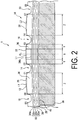
- FIG. 2 is an enlarged meridian cross-sectional view illustrating a region of the tread surface of FIG. 1 .
- the two circumferential main grooves 14, 16 located on both sides in the tire width direction of the center land portion 22 include four tire width direction end points E1, E2, E3, E4, and a contour line L1 of the tread surface corresponds to an arc including the two points E2, E3 by which the center land portion 22 is demarcated and further including at least one of the end points E1, E4 (in the example illustrated in FIG. 2 , the arc including all of the end points E1 to E4).
- the tire profile line (solid line in FIG. 2 ) of the center land portion 22 projects outward in the tire radial direction with respect to the contour line L1 of the tread surface.
- the two circumferential main grooves 18, 14 (16, 20) located on both sides in the tire width direction of the second land portion 24 (26) include four tire width direction end points E5, E6, E1, E2 (E3, E4, E7, E8), and a contour line L2 (L2) of the tread surface corresponds to an arc including the two points E6, E1 (E4, E7) by which the second land portion 24 (26) is demarcated and further including at least one of the end points E5, E2 (E3, E8) (in the example illustrated in FIG. 2 , the arc including all of the end points E5, E6, E1, E2 (E3, E4, E7, E8)).
- the tire profile line (solid line in FIG. 2 ) of the second land portion 24 (26) projects outward in the tire radial direction with respect to the contour line L2 (L2) of the tread surface.
- a projection amount Pc of the center land portion refers to the maximum projection amount outward in the tire radial direction from the contour line L1 of the tread surface to the tire profile line (solid line in FIG. 2 ), as illustrated in FIG. 2 .
- a projection amount Ps of the second land portion refers to the maximum projection amount outward in the tire radial direction from the contour line L2 (L2) of the tread surface to the tire profile line (solid line in FIG. 2 ).
- a ratio Pc/Ps between the projection amount Pc of the center land portion 22 and the projection amount Ps of the second land portion 24 (26) is 0.50 or more and 0.70 or less.
- the ratio Pc/Ps between both projection amounts being 0.50 or more enables avoidance of a significant difference in ground contact pressures between the center land portion 22 and the second land portion 24 (26) to suppress heat build-up, and further allows excellent high-speed durability performance to be delivered.
- the ratio Pc/Ps between both projection amounts being 0.70 or less allows further suppression of protrusion of the tire width direction center region, allowing even further suppression of an increase in the tire ground contact length. This enables suppression of a difference in the ground contact pressure between the tire width direction region X and the tire width direction region Y, thus allowing excellent high-speed durability performance to be delivered.
- the projection amount Pc of the center land portion 22 is 0.05 mm or more and 0.20 mm or less, and in a case where the center cover layer 34b has a thickness of 0.40 mm or more and 1.00 mm or less, the projection amount Pc of the center land portion 22 is 0.25 mm or more and 0.50 mm or less, and in a case where the center cover layer 34b has a thickness of 1.00 mm or more and 1.50 mm or less, the projection amount Pc of the center land portion 22 is 0.50 mm or more and 0.75 mm or less (Additional Embodiment 4).
- protrusion of the center land portion 22 in the tire radial direction during traveling is suppressed without an excessive increase in the projection amount Pc of the center land portion 22 with respect to the thickness of the center cover layer 34b, and a significant difference in the ground contact pressure from the second land portion 24 (26) is avoided, suppressing heat build-up. This allows more excellent high-speed durability performance to be delivered.
- the center cover layer 34b illustrated in FIGS. 1 and 2 preferably includes organic fiber cords of nylon and aramid intertwined (Additional Embodiment 5).
- the center cover layer 34b includes organic fiber cords formed by intertwining nylon having a relatively high elongation and aramid having a relatively high strength, allowing an excessive ground contact length to be suppressed compared to the center cover layer 34b including steel cords. Additionally, deflection of the tread portion can be suppressed, reducing heat build-up, and thus high-speed durability performance can be efficiently improved.
- the band-like sound absorbing member 38 illustrated in FIGS. 1 and 2 is preferably discontinuous in at least one section in the tire circumferential direction (Additional Embodiment 6).
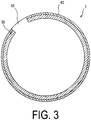
- FIG. 3 is a tire side cross-sectional view illustrating a pneumatic tire according to an embodiment of the present invention.
- FIG. 3 illustrates only the portion of the pneumatic tire 1 illustrated in FIGS. 1 and 2 which is located further on the inner side than the innerliner 28 in the tire radial direction, and the band-like sound absorbing member 38 is attached to the tire inner cavity via the adhesive 40.
- one section of the band-like sound absorbing member 38 in the tire circumferential direction is discontinuous, and this portion corresponds to a gap portion 42.
- the band-like sound absorbing member 38 is discontinuous in at least one section in the tire circumferential direction to define the gap portion 42.
- the tires have a tire size of 275/40R21 107Y, include the components illustrated in FIG. 1 (innerliner 28, carcass layer 30, belt layer 32 (belts 32a to 32c), belt cover layer 34 (full cover layer 34a and center cover layer 34b), tread rubber layer 36, and band-like sound absorbing member 38), and the center land portion 22 and the second land portion 24 (26) illustrated in FIG. 1 , and satisfy conditions indicated in Tables 1 and 2 below.
- the tread average thickness A is the tread average thickness in the tire width direction region X of the center land portion 22 where the center cover layer 34b is disposed as illustrated in FIG. 2
- the tread average thickness B is the tread average thickness in the tire width direction region Y of the center land portion 22 where the center cover layer 34b is not disposed as illustrated in FIG. 2
- the tread average thickness C is the tread average thickness in the tire width direction region Z where the second land portion 24 (26) located further on the outer side than the center land portion 22 in the tire width direction and adjacent to the center land portion 22 is defined and formed as illustrated in FIG. 2 .
- Pc denotes a maximum projection amount of outward projection of the center land portion 22 in the tire radial direction from the contour line L1 of the tread surface to the tire profile line (solid line in FIG. 2 ) as illustrated in FIG. 2
- Ps denotes a maximum projection amount of outward projection of the second land portion 24 (26) in the tire radial direction from the contour line L2 of the tread surface to the tire profile line (solid line in FIG. 2 ) as illustrated in FIG. 2 .
- Example 2 Tread average thickness Relationship between A and B and C A>B ⁇ C A ⁇ B>C A>B>C A ⁇ B ⁇ C A ⁇ B ⁇ C Ratio A/B 1.05 0.65 1.05 0.65 0.75 Ratio B/C 0.88 1.02 1.02 0.88 0.88 Ratio Pc/Ps 0.45 0.45 0.45 0.45 Thickness of center cover layer (mm), projection amount Pc (mm) 0.70 0.70 0.70 0.70 0.70 0.20 0.20 0.20 0.20 0.20 0.20 0.20 0.20 Cord type used in center cover layer Organic fibers Cords Nylon Organic fibers Cords Nylon Organic fibers Cords Nylon Organic fibers Cords Nylon Organic fibers Cords Nylon Organic fibers Cords Nylon Organic fibers Cords Nylon Organic fibers Cords Nylon Whether band-like sound absorbing member is discontinuous Continuous Continuous Continuous Continuous Continuous Continuous Continuous Continuous Continuous Continuous Continuous Continuous Continuous Continuous Continuous
- Example 3 Example 4
- Example 6 Example 7 Tread average thickness Relationship between A and B and C A ⁇ B ⁇ C A ⁇ B ⁇ C
- the test tires were assembled on wheels having a rim size of 21 x 9.5J (ETRO standard rim) and inflated to an air pressure of 220 kPa (Reinforced/Extra Load Tires).
- Tire failure tests (in compliance with JIS K 6302) were conducted in which a plunger with a plunger diameter of 19 ⁇ 1.6 mm was pressed against the central portion of the tread under a load speed (plunger pressing speed) of 50.0 ⁇ 1.5 m/min, and tire strength (tire failure energy) was measured.
- the actual value (unit: j) of the measured failure energy was converted into an index with Conventional Example being assigned as the reference (100). Larger values indicate higher failure energy and excellent shock burst resistance (Tables 3, 4).
- each of the test tires described above was set in an indoor drum testing machine (drum radius: 854 mm), inflated to an air pressure of 360 kPa, and loaded with a load of 7.26 kN.
- Pre-running was performed at a speed of 50 km/hr for 30 minutes, and then with the load set to 7.26 kN, the speed was gradually increased from 260 km/hr by 10 km/hr per 10 minutes.
- the speed at the time of tire failure was measured.
- time of tire failure refers to the point in time when rubber and a cord or rubber and rubber were confirmed peeled off and damaged. Index evaluation was conducted based on the measured speeds with Conventional Example being assigned as the reference (100).
Abstract
Description
- The present invention relates to a pneumatic tire that provides both shock burst resistance performance and high-speed durability performance in a compatible manner.
- An extra road tire is used at a relatively high air pressure, and thus during traveling, the tire may be greatly shocked and damaged (shock burst) due to, for example, breakage of a carcass. Thus, the extra road tire is required to ensure shock burst resistance performance.
- In order to ensure shock burst resistance performance, a reinforcing layer may be provided in a region (the tire width direction center region) located near a tire equatorial plane on which the highest load is placed during traveling, the region including the tire equatorial plane. For example, a means is known in which a full cover layer is provided to completely cover a tire width direction region, on an outer side of a belt layer in a tire radial direction, and in which a center cover layer is provided in a tire width direction center region on an outer side of the full cover layer in the tire radial direction (Patent Document 1). Employing such a configuration allows the tire width direction center region to be locally reinforced on the outer side of the belt layer in the tire radial direction, ensuring shock burst resistance performance.
- Patent Document 1:
JP 2017-137032 A - However, providing a center cover layer increases tread gauge in the center region. This markedly appears particularly in the extra road tire, which is used at a relatively high air pressure, and an excessive load is applied to the portion with the increased tread gauge, thus increasing the tire ground contact length and making the ground contact pressure in this portion significantly different from the ground contact pressure in the other portions. This may prevent excellent high-speed durability performance from being delivered.
- In addition, in particular, in a case where a band-like sound absorbing member is installed in a tire cavity as in the technology disclosed in
Patent Document 1, heat accumulated in the band-like sound absorbing member at high speeds degrades the band-like sound absorbing member or a rubber layer disposed in proximity to the band-like sound absorbing member. This may prevent excellent high-speed durability performance from being delivered. - In light of the foregoing, an object of the present invention is to provide a pneumatic tire that allows, on the precondition that shock burst resistance performance is ensured, excellent high-speed durability performance to be delivered even in a case where a band-like sound absorbing member is installed in a tire cavity.
- An embodiment of the present invention provides a pneumatic tire comprising a tread portion provided with at least three circumferential main grooves defining and forming at least two center land portions,
- the tread portion comprising at least one full cover layer disposed on an outer side of a belt layer in a tire radial direction and covering the belt layer by entire width thereof and at least one center cover layer disposed on an outer side of the full cover layer in the tire radial direction and locally covering a central region of the belt layer in a tire width direction,
- a band-like sound absorbing member being formed on an inner side of an innerliner in the tire radial direction, and
- a tread average thickness A in a tire width direction region of the center land portion in which the center cover layer is disposed, a tread average thickness B in a tire width direction region of the center land portion in which the center cover layer is not disposed, and a tread average thickness C in second land portions located further on an outer side than the center land portion in the tire width direction and located adjacent to the center land portion satisfying a relationship A < B < C.
- In the pneumatic tire according to an embodiment of the present invention, improvements are made to the tread average thickness in the center land portion and the second land portion. As a result, in the pneumatic tire according to an embodiment of the present invention, on the precondition that shock burst resistance performance is ensured, excellent high-speed durability performance can be delivered even in a case where a band-like sound absorbing member is installed in a tire cavity.
-
-
FIG. 1 is a tire cross-sectional view illustrating a tread portion of a pneumatic tire according to an embodiment of the present invention. -
FIG. 2 is a tire meridian cross-sectional view illustrating a tread portion of a pneumatic tire according to an embodiment of the present invention. -
FIG. 3 is a tire side cross-sectional view illustrating a pneumatic tire according to an embodiment of the present invention. - Pneumatic tires according to embodiments (including Basic Embodiment and
Additional Embodiments 1 to 6) of the present invention are described below based on the drawings. Note that the present invention is not limited to these embodiments. Furthermore, constituents of the embodiment include elements that can be substituted or easily conceived by one skilled in the art or that are essentially identical. In addition, the various modes included in the embodiments can be combined as desired within the scope of obviousness by one skilled in the art. - The following is a description of the Basic Embodiment of the pneumatic tire according to an embodiment of the present invention.
- Herein, "tire radial direction" refers to the direction orthogonal to the rotation axis of the pneumatic tire. "inner side in the tire radial direction" refers to the direction toward the rotation axis in the tire radial direction. "outer side in the tire radial direction" refers to the direction away from the rotation axis in the tire radial direction. In addition, "tire circumferential direction" refers to the circumferential direction with the rotation axis as the center axis. "Tire width direction" refers to the direction parallel with the rotation axis. "inner side in the tire width direction" refers to the direction toward a tire equatorial plane CL (tire equator line) in the tire width direction. "outer side in the tire width direction" refers to the direction away from the tire equatorial plane CL in the tire width direction. Note that "tire equatorial plane CL" refers to the plane that is orthogonal to the rotation axis of the pneumatic tire and that passes through the center of the tire width of the pneumatic tire.
-
FIG. 1 is a tire meridian cross-sectional view illustrating a tread portion of a pneumatic tire according to an embodiment of the present invention. Additionally, the pneumatic tire illustrated in the same drawing is mounted on a regular rim and inflated to an air pressure of 180 kPa or more and 350 kPa or less, and loaded with from 50% to 95% of a regular load. Note that "meridian cross-sectional view of the pneumatic tire" is a view illustrating the cross-sectional shape of the pneumatic tire appearing on a plane normal to the tire equatorial plane. - Here, "regular rim" refers to a "standard rim" defined by JATMA, a "Design Rim" defined by TRA, or a "Measuring Rim" defined by ETRTO. Additionally, "regular load" refers to a "maximum load capacity" defined by JATMA, the maximum value in "TIRE LOAD LIMITS AT VARIOUS COLD INFLATION PRESSURES" defined by TRA, or "LOAD CAPACITY" defined by ETRTO.
- A
pneumatic tire 1 illustrated in the same drawing includes atread portion 10. Thetread portion 10 is made of a rubber member (tread rubber) or the like and is located on the outermost side of thepneumatic tire 1 in the tire radial direction, with the surface of thetread portion 10 constituting the contour of thepneumatic tire 1. The surface of the tread portion is formed as atread surface 12, corresponding to a surface that comes into contact with the road surface when a vehicle (not illustrated) equipped with the pneumatic tire is traveling. - As illustrated in
FIG. 1 , thetread surface 12 includes at least two land portions and inFIG. 1 , threeland portions FIG. 1 , four circumferentialmain grooves - Here, "circumferential main groove" refers to a groove having a groove width (maximum width) of 7.5 mm or more and 8.5 mm or less, and a groove depth (maximum groove depth) of 7.0 mm or more and 8.5 mm or less.
- Additionally, for three circumferential main grooves (not illustrated), the two land portions located in the central portion in the tire width direction correspond to the center land portion, and the land portion closest to the center land portion on the outer side in the tire width direction correspond to the second land portion. Additionally, in a case where four circumferential main grooves are present (as illustrated in
FIG. 1 ), the twoland portions 22 located in the central portion in the tire width direction correspond to the center land portion, and theland portions - Additionally, in the pneumatic tire according to the present embodiment, as illustrated in
FIG. 1 , aninnerliner 28, acarcass layer 30, a belt layer 32 (belts 32a to 32c), a belt cover layer 34 (afull cover layer 34a and acenter cover layer 34b), and atread rubber layer 36 are provided in this order from the inner side toward the outer side in the tire radial direction. - In other words, on the outer side in the tire radial direction of the
belt layer 32, at least one full cover layer covering thebelt layer 32 by entire width thereof is disposed, and inFIG. 1 , onefull cover layer 34a is disposed. Additionally, on the outer side of thefull cover layer 34a in the tire radial direction, at least onecenter cover layer 34b locally covering a central region of thebelt layer 32 in the tire width direction is disposed, and inFIG. 1 , onecenter cover layer 34b is disposed. - Furthermore, in the pneumatic tire according to the present embodiment, a band-like
sound absorbing member 38 is formed on the inner side of theinnerliner 28 in the tire radial direction, as illustrated inFIG. 1 . The band-likesound absorbing member 38 is formed from a porous material with open cells, and has predetermined sound absorbing properties based on the porous structure. For example, polyurethane foam can be used as the porous material constituting the band-likesound absorbing member 38. The band-likesound absorbing member 38 is bonded to theinnerliner 28 via, for example, anadhesive layer 40 to a region on the tire inner surface corresponding to thetread portion 10. For example, a double-sided tape is preferably used as theadhesive layer 40. - On such preconditions, in the pneumatic tire according to the present embodiment, a tread average thickness A in a tire width direction region X of the
center land portion 22 where thecenter cover layer 34b is disposed; a tread average thickness B in tire width direction regions Y of thecenter land portion 22 where thecenter cover layer 34b is not disposed; and a tread average thickness C in tire width direction regions Z where thesecond land portions center land portion 22 in the tire width direction and adjacent to thecenter land portion 22 are defined and formed satisfy a relationship A < B < C. - Here, "tread average thicknesses A, B, C" respectively refer to the average thicknesses from the innermost position of the
innerliner 28 in the tire radial direction to the tire surface, in the tire width direction region X of thecenter land portion 22, the tire width direction regions Y, Y of thecenter land portion 22, and the tire width direction regions Z, Z of thesecond land portions center cover layer 34b in the tire width direction and the central position between the end positions in the tire width direction. For the average thickness B, three sections measured including two sections corresponding to both end positions of the tire width direction region Y in the tire width direction and the central position between the end positions in the tire width direction. For the average thickness C, three sections are measured including both end positions of the tire width direction region Z in the tire width direction and the central position between the end positions in the tire width direction. - In the pneumatic tire according to the present embodiment, as illustrated in
FIG. 1 , thecenter cover layer 34b that locally covers the central region of thebelt layer 32 in the tire width direction is provided on the outer side of thefull cover layer 34a in the tire radial direction. This allows reinforcement of the tire width direction center region to which the heaviest load is applied during traveling, allowing shock burst resistance performance to be ensured (effect 1). - Additionally, in the pneumatic tire according to the present embodiment, as illustrated in
FIG. 1 , the band-likesound absorbing member 38 is installed in the tire cavity, and thus heat accumulated in the band-likesound absorbing member 38 at high speeds is assumed to degrade the band-likesound absorbing member 38 and the rubber layer disposed in proximity to the band-likesound absorbing member 38. However, in the pneumatic tire according to this embodiment, as illustrated inFIG. 1 , the tread average thicknesses A, B in thecenter land portion 22 are fluctuated in the tire width direction (A < B), and the tread average thicknesses B, C in thecenter land portion 22 and thesecond land portions FIG. 1 , the tread average thickness is gradually increased from the tire equatorial plane CL toward the outer side in the tire width direction (A < B <C). Accordingly, during traveling, the tire width direction center region is prevented from protruding excessively outward, thus allowing suppression of an increase in the tire ground contact length and suppression of a difference in the ground contact pressure between the tire width direction center region and the other regions. This in turn allows excellent high-speed durability performance to be delivered (effect 2). - As described above, in the pneumatic tire according to the present embodiment, on the precondition that, by improving the tread average thicknesses in the center land portion and the second land portions, shock burst resistance performance is ensured (
effect 1 described above), even in a case where the band-like sound absorbing member is installed in the tire cavity, excellent high-speed durability performance can be delivered (effect 2 described above). This allows both shock burst resistance performance and high-speed durability performance to be achieved at a high level in a compatible manner. - Note that the pneumatic tire according to the present embodiment, like a known pneumatic tire not illustrated, includes a bead portion, a sidewall portion, and a tread portion in this order from inner side to outer side in the tire radial direction in a tire meridian cross-sectional view. The pneumatic tire includes, for example, in a tire meridian cross-sectional view, a carcass layer (member with
reference sign 30 inFIG. 1 ) that extends from the tread portion to the bead portions on both sides and is wound around a pair of bead cores, a belt layer and other layers (member withreference sign 32 inFIG. 1 ) sequentially formed on the outer side of the carcass layer in the tire radial direction. - Also, the pneumatic tire according to the present embodiment is obtained after carrying out the various normal manufacturing processes, in other words, a step of mixing the tire materials, a step of processing the tire materials, a step of molding the green tire, a vulcanization step, an inspection step after vulcanization, and the like. In a case where the pneumatic tire according to the present embodiment is manufactured, in particular desired circumferential main grooves and protrusion portions corresponding to land portions are formed on an inner wall of a vulcanization mold, which is used to perform vulcanization.
- Now,
Additional Embodiments 1 to 6 that can optionally be implemented on Basic Embodiment of the pneumatic tire according to an embodiment of the present invention will be described. - In Basic Embodiment, a ratio A/B of the tread average thickness A and the tread average thickness B is preferably not less than 0.70 and not less than 0.95 (Additional Embodiment 1). Setting the ratio A/B to 0.7 or more allows setting of an even larger tread average thickness A in the tire width direction region X including the tire equatorial plane and located closest to the central portion in the tire width direction. Thus, even in a case where the region X is greatly shocked during traveling, a shock burst can be suppressed at a higher level.
- In contrast, setting the ratio A/B to 0.95 or less allows suppression of protrusion of the region X in the tire radial direction during traveling, and allows avoidance of a significant difference in ground contact pressure from the other portions (particularly the tire width direction region Y) without causing an excess tire ground contact length. Thus, excellent high-speed durability performance can be delivered.
- Note that in a case where the ratio A/B is 0.85 or more and 0.90 or less, the above-described effects are preferably produced at even higher levels.
- In Basic Embodiment or an embodiment corresponding to Basic Embodiment to which
Additional Embodiment 1 is added, a ratio B/C of the tread average thickness B and the tread average thickness C is preferably 0.91 or more and 0.99 or less (Additional Embodiment 2). Setting the ratio B/C to 0.91 or more allows setting of an even larger tread average thickness B in the tire width direction region Y that is relatively close to the tire equatorial plane CL. Thus, even in a case where the region Y is greatly shocked during traveling, a shock burst can be suppressed at a higher level. - In contrast, by setting the ratio B/C to 0.99 or less, not only is the protrusion of the region Y in the tire radial direction during traveling further reduced to further suppress an increase in the tire ground contact length, but also a significant difference in ground contact pressure from the other portions (particularly the tire width direction region Z) is avoided to suppress heat build-up. Thus, more excellent high-speed durability performance can be delivered.
- Note that in a case where the above-described ratio B/C is 0.93 or more and 0.97 or less, the above-described effects are preferably produced at even higher levels.
- In Basic Embodiment or an embodiment corresponding to Basic Embodiment to which at least one of
Additional Embodiment 1 and Additional Embodiment 2 is added, in a case where the two circumferential main grooves located on both sides of each of the center land portion and the second land portion in the tire width direction include four tire width direction end points and a contour line of the tread surface corresponds to an arc passing through at least three of the four tire width direction end points, the three tire width direction end points including two points by which the land portion is demarcated, the arc including the center on the inner side in the tire radial direction, then tire profile lines of both center land portion and second land portion project outward in the tire radial direction with respect to the contour line of the tread surface, the projection amount of the center land portion is less than the projection amount of the second land portion, and a ratio between the projection amount of the center land portion and the projection amount of the second land portion is 0.50 or more and 0.70 or less (Additional Embodiment 3). -
FIG. 2 is an enlarged meridian cross-sectional view illustrating a region of the tread surface ofFIG. 1 . As illustrated inFIG. 2 , the two circumferentialmain grooves center land portion 22 include four tire width direction end points E1, E2, E3, E4, and a contour line L1 of the tread surface corresponds to an arc including the two points E2, E3 by which thecenter land portion 22 is demarcated and further including at least one of the end points E1, E4 (in the example illustrated inFIG. 2 , the arc including all of the end points E1 to E4). At this time, the tire profile line (solid line inFIG. 2 ) of thecenter land portion 22 projects outward in the tire radial direction with respect to the contour line L1 of the tread surface. - Similarly, as illustrated in
FIG. 2 , the two circumferentialmain grooves 18, 14 (16, 20) located on both sides in the tire width direction of the second land portion 24 (26) include four tire width direction end points E5, E6, E1, E2 (E3, E4, E7, E8), and a contour line L2 (L2) of the tread surface corresponds to an arc including the two points E6, E1 (E4, E7) by which the second land portion 24 (26) is demarcated and further including at least one of the end points E5, E2 (E3, E8) (in the example illustrated inFIG. 2 , the arc including all of the end points E5, E6, E1, E2 (E3, E4, E7, E8)). In this case, the tire profile line (solid line inFIG. 2 ) of the second land portion 24 (26) projects outward in the tire radial direction with respect to the contour line L2 (L2) of the tread surface. - In this regard, for the
center land portion 22, a projection amount Pc of the center land portion refers to the maximum projection amount outward in the tire radial direction from the contour line L1 of the tread surface to the tire profile line (solid line inFIG. 2 ), as illustrated inFIG. 2 . Similarly, for the second land portion 24 (26), a projection amount Ps of the second land portion refers to the maximum projection amount outward in the tire radial direction from the contour line L2 (L2) of the tread surface to the tire profile line (solid line inFIG. 2 ). - On these preconditions, in the example illustrated in
FIG. 2 , a ratio Pc/Ps between the projection amount Pc of thecenter land portion 22 and the projection amount Ps of the second land portion 24 (26) is 0.50 or more and 0.70 or less. - The ratio Pc/Ps between both projection amounts being 0.50 or more enables avoidance of a significant difference in ground contact pressures between the
center land portion 22 and the second land portion 24 (26) to suppress heat build-up, and further allows excellent high-speed durability performance to be delivered. - In contrast, the ratio Pc/Ps between both projection amounts being 0.70 or less allows further suppression of protrusion of the tire width direction center region, allowing even further suppression of an increase in the tire ground contact length. This enables suppression of a difference in the ground contact pressure between the tire width direction region X and the tire width direction region Y, thus allowing excellent high-speed durability performance to be delivered.
- Note that in a case where the ratio Pc/Ps is 0.55 or more and 0.65 or less, the above-described effects are more preferably produced at higher levels.
- Preferably, in an embodiment corresponding to the Basic Embodiment to which at least Additional Embodiment 3 is added, in a case where the
center cover layer 34b illustrated inFIG. 2 has a thickness of 0.10 mm or more and 0.40 mm or less, the projection amount Pc of thecenter land portion 22 is 0.05 mm or more and 0.20 mm or less, and in a case where thecenter cover layer 34b has a thickness of 0.40 mm or more and 1.00 mm or less, the projection amount Pc of thecenter land portion 22 is 0.25 mm or more and 0.50 mm or less, and in a case where thecenter cover layer 34b has a thickness of 1.00 mm or more and 1.50 mm or less, the projection amount Pc of thecenter land portion 22 is 0.50 mm or more and 0.75 mm or less (Additional Embodiment 4). - As described above, by specifying, in a coordinative manner, the thickness of the
center cover layer 34b and the projection amount Pc of outward projection of thecenter land portion 22 in the tire radial direction, a certain projection amount Pc of thecenter land portion 22 is ensured with respect to the thickness of thecenter cover layer 34b, allowing shock burst resistance performance to be achieved at a higher level. - In contrast, protrusion of the
center land portion 22 in the tire radial direction during traveling is suppressed without an excessive increase in the projection amount Pc of thecenter land portion 22 with respect to the thickness of thecenter cover layer 34b, and a significant difference in the ground contact pressure from the second land portion 24 (26) is avoided, suppressing heat build-up. This allows more excellent high-speed durability performance to be delivered. - In Basic Embodiment or an embodiment corresponding to Basic Embodiment to which
Additional Embodiment 1 or the like is added, thecenter cover layer 34b illustrated inFIGS. 1 and2 preferably includes organic fiber cords of nylon and aramid intertwined (Additional Embodiment 5). Thecenter cover layer 34b includes organic fiber cords formed by intertwining nylon having a relatively high elongation and aramid having a relatively high strength, allowing an excessive ground contact length to be suppressed compared to thecenter cover layer 34b including steel cords. Additionally, deflection of the tread portion can be suppressed, reducing heat build-up, and thus high-speed durability performance can be efficiently improved. - In Basic Embodiment or an embodiment corresponding to Basic Embodiment to which
Additional Embodiment 1 or the like is added, the band-likesound absorbing member 38 illustrated inFIGS. 1 and2 is preferably discontinuous in at least one section in the tire circumferential direction (Additional Embodiment 6). -
FIG. 3 is a tire side cross-sectional view illustrating a pneumatic tire according to an embodiment of the present invention.FIG. 3 illustrates only the portion of thepneumatic tire 1 illustrated inFIGS. 1 and2 which is located further on the inner side than theinnerliner 28 in the tire radial direction, and the band-likesound absorbing member 38 is attached to the tire inner cavity via the adhesive 40. As illustrated inFIG. 1 , one section of the band-likesound absorbing member 38 in the tire circumferential direction is discontinuous, and this portion corresponds to agap portion 42. - The band-like
sound absorbing member 38 is discontinuous in at least one section in the tire circumferential direction to define thegap portion 42. Thus, in a tire rolling state in which the tire is filled with air and loaded, the shear strain on the adhering surface at which the band-likesound absorbing member 38 is bonded to the innerliner can be alleviated. Accordingly, heat build-up between the band-likesound absorbing member 38 and theinnerliner 28 can be suppressed, allowing more excellent high-speed durability performance to be delivered. - Pneumatic tires according to Conventional Example, Comparative Examples 1 and 2, and Examples 1 to 7 were manufactured. The tires have a tire size of 275/40R21 107Y, include the components illustrated in
FIG. 1 (innerliner 28,carcass layer 30, belt layer 32 (belts 32a to 32c), belt cover layer 34 (full cover layer 34a andcenter cover layer 34b), treadrubber layer 36, and band-like sound absorbing member 38), and thecenter land portion 22 and the second land portion 24 (26) illustrated inFIG. 1 , and satisfy conditions indicated in Tables 1 and 2 below. - Here, in Tables 1 and 2 below, the tread average thickness A is the tread average thickness in the tire width direction region X of the
center land portion 22 where thecenter cover layer 34b is disposed as illustrated inFIG. 2 , the tread average thickness B is the tread average thickness in the tire width direction region Y of thecenter land portion 22 where thecenter cover layer 34b is not disposed as illustrated inFIG. 2 , and the tread average thickness C is the tread average thickness in the tire width direction region Z where the second land portion 24 (26) located further on the outer side than thecenter land portion 22 in the tire width direction and adjacent to thecenter land portion 22 is defined and formed as illustrated inFIG. 2 . Additionally, Pc denotes a maximum projection amount of outward projection of thecenter land portion 22 in the tire radial direction from the contour line L1 of the tread surface to the tire profile line (solid line inFIG. 2 ) as illustrated inFIG. 2 , and Ps denotes a maximum projection amount of outward projection of the second land portion 24 (26) in the tire radial direction from the contour line L2 of the tread surface to the tire profile line (solid line inFIG. 2 ) as illustrated inFIG. 2 .[Table 1] Conventional Example Comparative Example 1 Comparative Example 2 Example 1 Example 2 Tread average thickness Relationship between A and B and C A>B<C A<B>C A>B>C A<B<C A<B<C Ratio A/B 1.05 0.65 1.05 0.65 0.75 Ratio B/C 0.88 1.02 1.02 0.88 0.88 Ratio Pc/Ps 0.45 0.45 0.45 0.45 0.45 Thickness of center cover layer (mm), projection amount Pc (mm) 0.70 0.70 0.70 0.70 0.70 0.20 0.20 0.20 0.20 0.20 Cord type used in center cover layer Organic fibers Cords Nylon Organic fibers Cords Nylon Organic fibers Cords Nylon Organic fibers Cords Nylon Organic fibers Cords Nylon Whether band-like sound absorbing member is discontinuous Continuous Continuous Continuous Continuous Continuous [Table 2] Example 3 Example 4 Example 5 Example 6 Example 7 Tread average thickness Relationship between A and B and C A<B<C A<B<C A<B<C A<B<C A<B<C Ratio A/B 0.75 0.75 0.75 0.75 0.75 Ratio B/C 0.97 0.97 0.97 0.97 0.97 Ratio Pc/Ps 0.45 0.55 0.55 0.55 0.55 Thickness of center cover layer (mm), and projection amount Pc (mm) 0.70 0.70 0.70 0.70 0.70 0.20 0.20 0.35 0.35 0.35 Cord type used in center cover layer Organic fibers Cords Nylon Organic fibers Cords Nylon Organic fibers Cords Nylon Organic fibers Cords Nylon and aramid Organic fibers Cords Nylon and aramid Whether band-like sound absorbing member is discontinuous Continuous Continuous Continuous Continuous Discontinuous Gap portion present - The test tires were assembled on wheels having a rim size of 21 x 9.5J (ETRO standard rim) and inflated to an air pressure of 220 kPa (Reinforced/Extra Load Tires). Tire failure tests (in compliance with JIS K 6302) were conducted in which a plunger with a plunger diameter of 19±1.6 mm was pressed against the central portion of the tread under a load speed (plunger pressing speed) of 50.0±1.5 m/min, and tire strength (tire failure energy) was measured. The actual value (unit: j) of the measured failure energy was converted into an index with Conventional Example being assigned as the reference (100). Larger values indicate higher failure energy and excellent shock burst resistance (Tables 3, 4).
- Next, each of the test tires described above was set in an indoor drum testing machine (drum radius: 854 mm), inflated to an air pressure of 360 kPa, and loaded with a load of 7.26 kN. Pre-running was performed at a speed of 50 km/hr for 30 minutes, and then with the load set to 7.26 kN, the speed was gradually increased from 260 km/hr by 10 km/hr per 10 minutes. The speed at the time of tire failure was measured. Here, "time of tire failure" refers to the point in time when rubber and a cord or rubber and rubber were confirmed peeled off and damaged. Index evaluation was conducted based on the measured speeds with Conventional Example being assigned as the reference (100). In the evaluation, larger index values indicate higher speeds at the time of tire failure and more excellent high-speed durability performance (Tables 3, 4).
[Table 3] Conventional example Comparative Example 1 Comparative Example 2 Example 1 Example 2 Shock burst resistance performance 100 97 100 100 103 High-speed durability performance 100 94 91 103 103 [Table 4] Example 3 Example 4 Example 5 Example 6 Example 7 Shock burst resistance performance 106 106 108 110 110 High-speed durability performance 106 108 108 108 110 - According to Tables 1 to 4, all of the pneumatic tires in Examples 1 to 7, which belong to the technical scope of the present invention (where the tread average thicknesses A, B, C satisfy the predetermined relationship) achieve both shock burst resistance performance and high-speed durability performance at a higher level than the pneumatic tires in Conventional Example and Comparative Examples 1 and 2, which do not belong to the technical scope of the present invention.
-
- 1 Pneumatic tire
- 10 Tread portion
- 12 Tread surface
- 14, 16, 18, 20 Circumferential main groove
- 22 Center land portion
- 24, 26 Second land portion
- 28 Innerliner
- 30 Carcass layer
- 32 Belt layer
- 32a, 32b, 32c Belt
- 34 Belt cover layer
- 34a Full cover layer
- 34b Center cover layer
- 36 Tread rubber layer
- 38 Band-like sound absorbing member
- 40 Adhesive
- 42 Gap portion
- CL Tire equatorial plane
- E1, E2, E3, E4, E5, E6, E6, E7, E8 Tire width direction end point
- X, Y, Z Tire width direction region
Claims (7)
- A pneumatic tire, comprising:a tread portion provided with at least three circumferential main grooves defining and forming at least two center land portions,the tread portion comprising at least one full cover layer disposed on an outer side of a belt layer in a tire radial direction and covering the belt layer by entire width thereof and at least one center cover layer disposed on an outer side of the full cover layer in the tire radial direction and locally covering a central region of the belt layer in a tire width direction,a band-like sound absorbing member being formed on an inner side of an innerliner in the tire radial direction, anda tread average thickness A in a tire width direction region of the center land portion in which the center cover layer is disposed, a tread average thickness B in a tire width direction region of the center land portion in which the center cover layer is not disposed, and a tread average thickness C in second land portions located further on an outer side than the center land portion in the tire width direction and located adjacent to the center land portion satisfying a relationship A < B < C.
- The pneumatic tire according to claim 1, wherein a ratio A/B between the tread average thickness A and the tread average thickness B is 0.70 or more and 0.95 or less.
- The pneumatic tire according to claim 1 or 2, wherein a ratio B/C between the tread average thickness B and the tread average thickness C is 0.91 or more and 0.99 or less.
- The pneumatic tire according to any one of claims 1 to 3, wherein in a case where two of the circumferential main grooves located on both sides of each of the center land portion and the second land portion in the tire width direction comprise four tire width direction end points and a contour line of a tread surface corresponds to an arc passing through at least three of the four tire width direction end points, the three tire width direction end points comprising two points by which the land portion is demarcated, the arc comprising a center on the inner side in the tire radial direction,tire profile lines of both center land portion and second land portion project outward in the tire radial direction with respect to the contour line of the tread surface, anda ratio between a projection amount of the center land portion and a projection amount of the second land portion is 0.50 or more and 0.70 or less.
- The pneumatic tire according to claim 4, whereinin a case where the center cover layer has a thickness of 0.10 mm or more and 0.40 mm or less, a projection amount of the center land portion is 0.05 mm or more and 0.20 mm or less,in a case where the center cover layer has a thickness of 0.40 mm or more and 1.00 mm or less, a projection amount of the center land portion is 0.25 mm or more and 0.50 mm or less, andin a case where the center cover layer has a thickness of 1.00 mm or more and 1.50 mm or less, a projection amount of the center land portion is 0.50 mm or more and 0.75 mm or less.
- The pneumatic tire according to any one of claims 1 to 5, wherein the center cover layer comprises organic fiber cords of nylon and aramid intertwined.
- The pneumatic tire according to any one of claims 1 to 6, wherein the band-like sound absorbing member is discontinuous in at least one section in a tire circumferential direction.
Applications Claiming Priority (2)
| Application Number | Priority Date | Filing Date | Title |
|---|---|---|---|
| JP2019015711A JP6835110B2 (en) | 2019-01-31 | 2019-01-31 | Pneumatic tires |
| PCT/JP2019/051004 WO2020158277A1 (en) | 2019-01-31 | 2019-12-25 | Pneumatic tire |
Publications (2)
| Publication Number | Publication Date |
|---|---|
| EP3919291A1 true EP3919291A1 (en) | 2021-12-08 |
| EP3919291A4 EP3919291A4 (en) | 2022-10-05 |
Family
ID=71840838
Family Applications (1)
| Application Number | Title | Priority Date | Filing Date |
|---|---|---|---|
| EP19912911.5A Pending EP3919291A4 (en) | 2019-01-31 | 2019-12-25 | Pneumatic tire |
Country Status (5)
| Country | Link |
|---|---|
| US (1) | US20220169079A1 (en) |
| EP (1) | EP3919291A4 (en) |
| JP (1) | JP6835110B2 (en) |
| CN (1) | CN113365852B (en) |
| WO (1) | WO2020158277A1 (en) |
Family Cites Families (28)
| Publication number | Priority date | Publication date | Assignee | Title |
|---|---|---|---|---|
| US5228933A (en) * | 1989-08-24 | 1993-07-20 | Bridgestone Corporation | High performance pneumatic radial tires |
| JPH0740705A (en) * | 1993-07-27 | 1995-02-10 | Bridgestone Corp | Pneumatic tire |
| JP3295527B2 (en) * | 1993-10-04 | 2002-06-24 | 株式会社ブリヂストン | Pneumatic tire |
| JPH0958215A (en) * | 1995-08-28 | 1997-03-04 | Bridgestone Corp | Radial tire |
| JP3808980B2 (en) * | 1997-02-21 | 2006-08-16 | 東洋ゴム工業株式会社 | Pneumatic radial tire |
| CA2294418A1 (en) * | 1997-06-20 | 1998-12-30 | Robert Ciprian Radulescu | Pneumatic tire including belt and circumferential ribs |
| US7036541B2 (en) * | 2001-10-19 | 2006-05-02 | Sumitomo Rubber Industries, Ltd. | Pneumatic tire |
| JP4707105B2 (en) * | 2005-11-15 | 2011-06-22 | 株式会社ブリヂストン | Pneumatic tire |
| KR101036373B1 (en) * | 2007-02-23 | 2011-05-23 | 가부시키가이샤 브리지스톤 | Pneumatic radial tire |
| JP5312233B2 (en) * | 2009-07-03 | 2013-10-09 | 東洋ゴム工業株式会社 | Pneumatic tire |
| JP2011126304A (en) * | 2009-12-15 | 2011-06-30 | Bridgestone Corp | Pneumatic tire |
| JP5390432B2 (en) * | 2010-02-25 | 2014-01-15 | 東洋ゴム工業株式会社 | Pneumatic tire |
| JP2011183879A (en) * | 2010-03-05 | 2011-09-22 | Bridgestone Corp | Tire |
| JP5707860B2 (en) * | 2010-10-28 | 2015-04-30 | 横浜ゴム株式会社 | Pneumatic tire |
| JP6050568B2 (en) * | 2011-06-20 | 2016-12-21 | 株式会社ブリヂストン | Pneumatic tire |
| US20130032262A1 (en) * | 2011-08-02 | 2013-02-07 | Bormann Rene Louis | Tire with foamed noise damper |
| JP6115003B2 (en) * | 2011-09-20 | 2017-04-19 | 横浜ゴム株式会社 | Pneumatic tire |
| JP5895576B2 (en) * | 2012-02-14 | 2016-03-30 | 横浜ゴム株式会社 | Pneumatic tire |
| JP6299219B2 (en) * | 2012-07-13 | 2018-03-28 | 横浜ゴム株式会社 | Pneumatic tire |
| JP6153763B2 (en) * | 2013-04-23 | 2017-06-28 | 東洋ゴム工業株式会社 | Pneumatic tire |
| US10723181B2 (en) * | 2014-01-23 | 2020-07-28 | The Yokohama Rubber Co., Ltd. | Pneumatic tire with specified tread rubber layer thickness and sound-absorbing member width |
| JP6269135B2 (en) * | 2014-02-12 | 2018-01-31 | 横浜ゴム株式会社 | Rehabilitation tire |
| DE102014208551A1 (en) * | 2014-05-07 | 2015-11-12 | Continental Reifen Deutschland Gmbh | Vehicle tires |
| JP6302861B2 (en) * | 2015-03-17 | 2018-03-28 | 横浜ゴム株式会社 | Pneumatic tire |
| JP2017013564A (en) * | 2015-06-29 | 2017-01-19 | 横浜ゴム株式会社 | Pneumatic tire, and method for manufacturing the same |
| JP6491564B2 (en) * | 2015-07-29 | 2019-03-27 | Toyo Tire株式会社 | Pneumatic tire |
| JP6658035B2 (en) | 2016-02-05 | 2020-03-04 | 横浜ゴム株式会社 | Pneumatic tire |
| JP6245304B2 (en) * | 2016-05-12 | 2017-12-13 | 横浜ゴム株式会社 | Pneumatic tire |
-
2019
- 2019-01-31 JP JP2019015711A patent/JP6835110B2/en active Active
- 2019-12-25 WO PCT/JP2019/051004 patent/WO2020158277A1/en unknown
- 2019-12-25 US US17/310,197 patent/US20220169079A1/en active Pending
- 2019-12-25 EP EP19912911.5A patent/EP3919291A4/en active Pending
- 2019-12-25 CN CN201980090618.2A patent/CN113365852B/en active Active
Also Published As
| Publication number | Publication date |
|---|---|
| CN113365852A (en) | 2021-09-07 |
| CN113365852B (en) | 2023-07-04 |
| US20220169079A1 (en) | 2022-06-02 |
| WO2020158277A1 (en) | 2020-08-06 |
| EP3919291A4 (en) | 2022-10-05 |
| JP2020121682A (en) | 2020-08-13 |
| JP6835110B2 (en) | 2021-02-24 |
Similar Documents
| Publication | Publication Date | Title |
|---|---|---|
| US6701986B2 (en) | Run-flat tire with tread reinforcing rubber layer | |
| KR101258195B1 (en) | Pneumatic tire | |
| US20220266631A1 (en) | Pneumatic Tire | |
| EP3318424B1 (en) | Pneumatic tire | |
| EP3919294A1 (en) | Pneumatic tire | |
| EP3599108A1 (en) | Pneumatic tire | |
| WO2014203909A1 (en) | Pneumatic tire | |
| EP3357715B1 (en) | Pneumatic tire | |
| JP6269306B2 (en) | Rehabilitation tire | |
| EP3597453B1 (en) | Pneumatic tyre | |
| EP3564045B1 (en) | Pneumatic tire for motorcycles | |
| JP6221788B2 (en) | Rehabilitation tire | |
| EP3919291A1 (en) | Pneumatic tire | |
| US7249622B2 (en) | Tire with deep tread grooves | |
| JP7335486B2 (en) | pneumatic tire | |
| EP3251876B1 (en) | Pneumatic tire | |
| US20180244113A1 (en) | Run flat tire and method for manufacturing same | |
| EP3871904B1 (en) | Pneumatic tire | |
| JP2015145143A (en) | retreaded tire | |
| JP6369184B2 (en) | Rehabilitation tire | |
| EP3366496B1 (en) | Run flat tire and method for manufacturing same | |
| EP3871903A1 (en) | Pneumatic tire | |
| JP7335485B2 (en) | pneumatic tire | |
| JP2017001432A (en) | Pneumatic tire | |
| JP2018075976A (en) | Pneumatic tire |
Legal Events
| Date | Code | Title | Description |
|---|---|---|---|
| STAA | Information on the status of an ep patent application or granted ep patent |
Free format text: STATUS: THE INTERNATIONAL PUBLICATION HAS BEEN MADE |
|
| PUAI | Public reference made under article 153(3) epc to a published international application that has entered the european phase |
Free format text: ORIGINAL CODE: 0009012 |
|
| STAA | Information on the status of an ep patent application or granted ep patent |
Free format text: STATUS: REQUEST FOR EXAMINATION WAS MADE |
|
| 17P | Request for examination filed |
Effective date: 20210714 |
|
| AK | Designated contracting states |
Kind code of ref document: A1 Designated state(s): AL AT BE BG CH CY CZ DE DK EE ES FI FR GB GR HR HU IE IS IT LI LT LU LV MC MK MT NL NO PL PT RO RS SE SI SK SM TR |
|
| DAV | Request for validation of the european patent (deleted) | ||
| DAX | Request for extension of the european patent (deleted) | ||
| A4 | Supplementary search report drawn up and despatched |
Effective date: 20220907 |
|
| RIC1 | Information provided on ipc code assigned before grant |
Ipc: B60C 11/04 20060101ALI20220901BHEP Ipc: B60C 11/00 20060101ALI20220901BHEP Ipc: B60C 9/22 20060101ALI20220901BHEP Ipc: B60C 9/18 20060101ALI20220901BHEP Ipc: B60C 9/00 20060101ALI20220901BHEP Ipc: B60C 5/00 20060101AFI20220901BHEP |
|
| RAP3 | Party data changed (applicant data changed or rights of an application transferred) |
Owner name: THE YOKOHAMA RUBBER CO., LTD. |
|
| STAA | Information on the status of an ep patent application or granted ep patent |
Free format text: STATUS: EXAMINATION IS IN PROGRESS |
|
| 17Q | First examination report despatched |
Effective date: 20240315 |