EP3919167A1 - Exhaust-gas cleaning filter - Google Patents
Exhaust-gas cleaning filter Download PDFInfo
- Publication number
- EP3919167A1 EP3919167A1 EP20794552.8A EP20794552A EP3919167A1 EP 3919167 A1 EP3919167 A1 EP 3919167A1 EP 20794552 A EP20794552 A EP 20794552A EP 3919167 A1 EP3919167 A1 EP 3919167A1
- Authority
- EP
- European Patent Office
- Prior art keywords
- exhaust gas
- pore
- partition
- narrow part
- purifying filter
- Prior art date
- Legal status (The legal status is an assumption and is not a legal conclusion. Google has not performed a legal analysis and makes no representation as to the accuracy of the status listed.)
- Granted
Links
Images








Classifications
-
- B—PERFORMING OPERATIONS; TRANSPORTING
- B01—PHYSICAL OR CHEMICAL PROCESSES OR APPARATUS IN GENERAL
- B01D—SEPARATION
- B01D53/00—Separation of gases or vapours; Recovering vapours of volatile solvents from gases; Chemical or biological purification of waste gases, e.g. engine exhaust gases, smoke, fumes, flue gases, aerosols
- B01D53/34—Chemical or biological purification of waste gases
- B01D53/92—Chemical or biological purification of waste gases of engine exhaust gases
- B01D53/94—Chemical or biological purification of waste gases of engine exhaust gases by catalytic processes
- B01D53/944—Simultaneously removing carbon monoxide, hydrocarbons or carbon making use of oxidation catalysts
-
- F—MECHANICAL ENGINEERING; LIGHTING; HEATING; WEAPONS; BLASTING
- F01—MACHINES OR ENGINES IN GENERAL; ENGINE PLANTS IN GENERAL; STEAM ENGINES
- F01N—GAS-FLOW SILENCERS OR EXHAUST APPARATUS FOR MACHINES OR ENGINES IN GENERAL; GAS-FLOW SILENCERS OR EXHAUST APPARATUS FOR INTERNAL-COMBUSTION ENGINES
- F01N3/00—Exhaust or silencing apparatus having means for purifying, rendering innocuous, or otherwise treating exhaust
- F01N3/08—Exhaust or silencing apparatus having means for purifying, rendering innocuous, or otherwise treating exhaust for rendering innocuous
- F01N3/10—Exhaust or silencing apparatus having means for purifying, rendering innocuous, or otherwise treating exhaust for rendering innocuous by thermal or catalytic conversion of noxious components of exhaust
-
- B—PERFORMING OPERATIONS; TRANSPORTING
- B01—PHYSICAL OR CHEMICAL PROCESSES OR APPARATUS IN GENERAL
- B01D—SEPARATION
- B01D46/00—Filters or filtering processes specially modified for separating dispersed particles from gases or vapours
- B01D46/24—Particle separators, e.g. dust precipitators, using rigid hollow filter bodies
- B01D46/2403—Particle separators, e.g. dust precipitators, using rigid hollow filter bodies characterised by the physical shape or structure of the filtering element
- B01D46/2418—Honeycomb filters
- B01D46/2425—Honeycomb filters characterized by parameters related to the physical properties of the honeycomb structure material
- B01D46/2429—Honeycomb filters characterized by parameters related to the physical properties of the honeycomb structure material of the honeycomb walls or cells
-
- B—PERFORMING OPERATIONS; TRANSPORTING
- B01—PHYSICAL OR CHEMICAL PROCESSES OR APPARATUS IN GENERAL
- B01D—SEPARATION
- B01D46/00—Filters or filtering processes specially modified for separating dispersed particles from gases or vapours
- B01D46/24—Particle separators, e.g. dust precipitators, using rigid hollow filter bodies
- B01D46/2403—Particle separators, e.g. dust precipitators, using rigid hollow filter bodies characterised by the physical shape or structure of the filtering element
- B01D46/2418—Honeycomb filters
- B01D46/2425—Honeycomb filters characterized by parameters related to the physical properties of the honeycomb structure material
- B01D46/24492—Pore diameter
-
- B—PERFORMING OPERATIONS; TRANSPORTING
- B01—PHYSICAL OR CHEMICAL PROCESSES OR APPARATUS IN GENERAL
- B01J—CHEMICAL OR PHYSICAL PROCESSES, e.g. CATALYSIS OR COLLOID CHEMISTRY; THEIR RELEVANT APPARATUS
- B01J35/00—Catalysts, in general, characterised by their form or physical properties
- B01J35/50—Catalysts, in general, characterised by their form or physical properties characterised by their shape or configuration
- B01J35/56—Foraminous structures having flow-through passages or channels, e.g. grids or three-dimensional [3D] monoliths
- B01J35/57—Honeycombs
-
- B—PERFORMING OPERATIONS; TRANSPORTING
- B01—PHYSICAL OR CHEMICAL PROCESSES OR APPARATUS IN GENERAL
- B01J—CHEMICAL OR PHYSICAL PROCESSES, e.g. CATALYSIS OR COLLOID CHEMISTRY; THEIR RELEVANT APPARATUS
- B01J35/00—Catalysts, in general, characterised by their form or physical properties
- B01J35/60—Catalysts, in general, characterised by their form or physical properties characterised by their surface properties or porosity
- B01J35/63—Pore volume
-
- B—PERFORMING OPERATIONS; TRANSPORTING
- B01—PHYSICAL OR CHEMICAL PROCESSES OR APPARATUS IN GENERAL
- B01J—CHEMICAL OR PHYSICAL PROCESSES, e.g. CATALYSIS OR COLLOID CHEMISTRY; THEIR RELEVANT APPARATUS
- B01J35/00—Catalysts, in general, characterised by their form or physical properties
- B01J35/60—Catalysts, in general, characterised by their form or physical properties characterised by their surface properties or porosity
- B01J35/64—Pore diameter
- B01J35/657—Pore diameter larger than 1000 nm
-
- C—CHEMISTRY; METALLURGY
- C04—CEMENTS; CONCRETE; ARTIFICIAL STONE; CERAMICS; REFRACTORIES
- C04B—LIME, MAGNESIA; SLAG; CEMENTS; COMPOSITIONS THEREOF, e.g. MORTARS, CONCRETE OR LIKE BUILDING MATERIALS; ARTIFICIAL STONE; CERAMICS; REFRACTORIES; TREATMENT OF NATURAL STONE
- C04B38/00—Porous mortars, concrete, artificial stone or ceramic ware; Preparation thereof
- C04B38/0006—Honeycomb structures
-
- C—CHEMISTRY; METALLURGY
- C04—CEMENTS; CONCRETE; ARTIFICIAL STONE; CERAMICS; REFRACTORIES
- C04B—LIME, MAGNESIA; SLAG; CEMENTS; COMPOSITIONS THEREOF, e.g. MORTARS, CONCRETE OR LIKE BUILDING MATERIALS; ARTIFICIAL STONE; CERAMICS; REFRACTORIES; TREATMENT OF NATURAL STONE
- C04B38/00—Porous mortars, concrete, artificial stone or ceramic ware; Preparation thereof
- C04B38/007—Porous mortars, concrete, artificial stone or ceramic ware; Preparation thereof characterised by the pore distribution, e.g. inhomogeneous distribution of pores
-
- F—MECHANICAL ENGINEERING; LIGHTING; HEATING; WEAPONS; BLASTING
- F01—MACHINES OR ENGINES IN GENERAL; ENGINE PLANTS IN GENERAL; STEAM ENGINES
- F01N—GAS-FLOW SILENCERS OR EXHAUST APPARATUS FOR MACHINES OR ENGINES IN GENERAL; GAS-FLOW SILENCERS OR EXHAUST APPARATUS FOR INTERNAL-COMBUSTION ENGINES
- F01N3/00—Exhaust or silencing apparatus having means for purifying, rendering innocuous, or otherwise treating exhaust
- F01N3/02—Exhaust or silencing apparatus having means for purifying, rendering innocuous, or otherwise treating exhaust for cooling, or for removing solid constituents of, exhaust
- F01N3/021—Exhaust or silencing apparatus having means for purifying, rendering innocuous, or otherwise treating exhaust for cooling, or for removing solid constituents of, exhaust by means of filters
- F01N3/022—Exhaust or silencing apparatus having means for purifying, rendering innocuous, or otherwise treating exhaust for cooling, or for removing solid constituents of, exhaust by means of filters characterised by specially adapted filtering structure, e.g. honeycomb, mesh or fibrous
- F01N3/0222—Exhaust or silencing apparatus having means for purifying, rendering innocuous, or otherwise treating exhaust for cooling, or for removing solid constituents of, exhaust by means of filters characterised by specially adapted filtering structure, e.g. honeycomb, mesh or fibrous the structure being monolithic, e.g. honeycombs
-
- F—MECHANICAL ENGINEERING; LIGHTING; HEATING; WEAPONS; BLASTING
- F01—MACHINES OR ENGINES IN GENERAL; ENGINE PLANTS IN GENERAL; STEAM ENGINES
- F01N—GAS-FLOW SILENCERS OR EXHAUST APPARATUS FOR MACHINES OR ENGINES IN GENERAL; GAS-FLOW SILENCERS OR EXHAUST APPARATUS FOR INTERNAL-COMBUSTION ENGINES
- F01N3/00—Exhaust or silencing apparatus having means for purifying, rendering innocuous, or otherwise treating exhaust
- F01N3/02—Exhaust or silencing apparatus having means for purifying, rendering innocuous, or otherwise treating exhaust for cooling, or for removing solid constituents of, exhaust
- F01N3/021—Exhaust or silencing apparatus having means for purifying, rendering innocuous, or otherwise treating exhaust for cooling, or for removing solid constituents of, exhaust by means of filters
- F01N3/033—Exhaust or silencing apparatus having means for purifying, rendering innocuous, or otherwise treating exhaust for cooling, or for removing solid constituents of, exhaust by means of filters in combination with other devices
- F01N3/035—Exhaust or silencing apparatus having means for purifying, rendering innocuous, or otherwise treating exhaust for cooling, or for removing solid constituents of, exhaust by means of filters in combination with other devices with catalytic reactors
-
- F—MECHANICAL ENGINEERING; LIGHTING; HEATING; WEAPONS; BLASTING
- F01—MACHINES OR ENGINES IN GENERAL; ENGINE PLANTS IN GENERAL; STEAM ENGINES
- F01N—GAS-FLOW SILENCERS OR EXHAUST APPARATUS FOR MACHINES OR ENGINES IN GENERAL; GAS-FLOW SILENCERS OR EXHAUST APPARATUS FOR INTERNAL-COMBUSTION ENGINES
- F01N3/00—Exhaust or silencing apparatus having means for purifying, rendering innocuous, or otherwise treating exhaust
- F01N3/08—Exhaust or silencing apparatus having means for purifying, rendering innocuous, or otherwise treating exhaust for rendering innocuous
- F01N3/10—Exhaust or silencing apparatus having means for purifying, rendering innocuous, or otherwise treating exhaust for rendering innocuous by thermal or catalytic conversion of noxious components of exhaust
- F01N3/103—Oxidation catalysts for HC and CO only
-
- B—PERFORMING OPERATIONS; TRANSPORTING
- B01—PHYSICAL OR CHEMICAL PROCESSES OR APPARATUS IN GENERAL
- B01D—SEPARATION
- B01D2255/00—Catalysts
- B01D2255/10—Noble metals or compounds thereof
- B01D2255/102—Platinum group metals
-
- B—PERFORMING OPERATIONS; TRANSPORTING
- B01—PHYSICAL OR CHEMICAL PROCESSES OR APPARATUS IN GENERAL
- B01D—SEPARATION
- B01D2255/00—Catalysts
- B01D2255/20—Metals or compounds thereof
- B01D2255/206—Rare earth metals
- B01D2255/2065—Cerium
-
- B—PERFORMING OPERATIONS; TRANSPORTING
- B01—PHYSICAL OR CHEMICAL PROCESSES OR APPARATUS IN GENERAL
- B01D—SEPARATION
- B01D2255/00—Catalysts
- B01D2255/20—Metals or compounds thereof
- B01D2255/207—Transition metals
- B01D2255/20715—Zirconium
-
- B—PERFORMING OPERATIONS; TRANSPORTING
- B01—PHYSICAL OR CHEMICAL PROCESSES OR APPARATUS IN GENERAL
- B01D—SEPARATION
- B01D2255/00—Catalysts
- B01D2255/20—Metals or compounds thereof
- B01D2255/209—Other metals
- B01D2255/2092—Aluminium
-
- B—PERFORMING OPERATIONS; TRANSPORTING
- B01—PHYSICAL OR CHEMICAL PROCESSES OR APPARATUS IN GENERAL
- B01D—SEPARATION
- B01D2255/00—Catalysts
- B01D2255/40—Mixed oxides
- B01D2255/407—Zr-Ce mixed oxides
-
- B—PERFORMING OPERATIONS; TRANSPORTING
- B01—PHYSICAL OR CHEMICAL PROCESSES OR APPARATUS IN GENERAL
- B01D—SEPARATION
- B01D2255/00—Catalysts
- B01D2255/90—Physical characteristics of catalysts
- B01D2255/92—Dimensions
- B01D2255/9205—Porosity
-
- B—PERFORMING OPERATIONS; TRANSPORTING
- B01—PHYSICAL OR CHEMICAL PROCESSES OR APPARATUS IN GENERAL
- B01D—SEPARATION
- B01D53/00—Separation of gases or vapours; Recovering vapours of volatile solvents from gases; Chemical or biological purification of waste gases, e.g. engine exhaust gases, smoke, fumes, flue gases, aerosols
- B01D53/34—Chemical or biological purification of waste gases
- B01D53/92—Chemical or biological purification of waste gases of engine exhaust gases
- B01D53/94—Chemical or biological purification of waste gases of engine exhaust gases by catalytic processes
- B01D53/9404—Removing only nitrogen compounds
- B01D53/9409—Nitrogen oxides
- B01D53/9431—Processes characterised by a specific device
-
- C—CHEMISTRY; METALLURGY
- C04—CEMENTS; CONCRETE; ARTIFICIAL STONE; CERAMICS; REFRACTORIES
- C04B—LIME, MAGNESIA; SLAG; CEMENTS; COMPOSITIONS THEREOF, e.g. MORTARS, CONCRETE OR LIKE BUILDING MATERIALS; ARTIFICIAL STONE; CERAMICS; REFRACTORIES; TREATMENT OF NATURAL STONE
- C04B2111/00—Mortars, concrete or artificial stone or mixtures to prepare them, characterised by specific function, property or use
- C04B2111/00474—Uses not provided for elsewhere in C04B2111/00
- C04B2111/00793—Uses not provided for elsewhere in C04B2111/00 as filters or diaphragms
-
- C—CHEMISTRY; METALLURGY
- C04—CEMENTS; CONCRETE; ARTIFICIAL STONE; CERAMICS; REFRACTORIES
- C04B—LIME, MAGNESIA; SLAG; CEMENTS; COMPOSITIONS THEREOF, e.g. MORTARS, CONCRETE OR LIKE BUILDING MATERIALS; ARTIFICIAL STONE; CERAMICS; REFRACTORIES; TREATMENT OF NATURAL STONE
- C04B2111/00—Mortars, concrete or artificial stone or mixtures to prepare them, characterised by specific function, property or use
- C04B2111/00474—Uses not provided for elsewhere in C04B2111/00
- C04B2111/0081—Uses not provided for elsewhere in C04B2111/00 as catalysts or catalyst carriers
-
- F—MECHANICAL ENGINEERING; LIGHTING; HEATING; WEAPONS; BLASTING
- F01—MACHINES OR ENGINES IN GENERAL; ENGINE PLANTS IN GENERAL; STEAM ENGINES
- F01N—GAS-FLOW SILENCERS OR EXHAUST APPARATUS FOR MACHINES OR ENGINES IN GENERAL; GAS-FLOW SILENCERS OR EXHAUST APPARATUS FOR INTERNAL-COMBUSTION ENGINES
- F01N2330/00—Structure of catalyst support or particle filter
- F01N2330/06—Ceramic, e.g. monoliths
-
- F—MECHANICAL ENGINEERING; LIGHTING; HEATING; WEAPONS; BLASTING
- F01—MACHINES OR ENGINES IN GENERAL; ENGINE PLANTS IN GENERAL; STEAM ENGINES
- F01N—GAS-FLOW SILENCERS OR EXHAUST APPARATUS FOR MACHINES OR ENGINES IN GENERAL; GAS-FLOW SILENCERS OR EXHAUST APPARATUS FOR INTERNAL-COMBUSTION ENGINES
- F01N2570/00—Exhaust treating apparatus eliminating, absorbing or adsorbing specific elements or compounds
- F01N2570/12—Hydrocarbons
-
- Y—GENERAL TAGGING OF NEW TECHNOLOGICAL DEVELOPMENTS; GENERAL TAGGING OF CROSS-SECTIONAL TECHNOLOGIES SPANNING OVER SEVERAL SECTIONS OF THE IPC; TECHNICAL SUBJECTS COVERED BY FORMER USPC CROSS-REFERENCE ART COLLECTIONS [XRACs] AND DIGESTS
- Y02—TECHNOLOGIES OR APPLICATIONS FOR MITIGATION OR ADAPTATION AGAINST CLIMATE CHANGE
- Y02T—CLIMATE CHANGE MITIGATION TECHNOLOGIES RELATED TO TRANSPORTATION
- Y02T10/00—Road transport of goods or passengers
- Y02T10/10—Internal combustion engine [ICE] based vehicles
- Y02T10/12—Improving ICE efficiencies
Definitions
- the present disclosure relates to an exhaust gas purifying filter used with carrying purification catalyst.
- particulate matter referred to as particulates is contained in an exhaust gas emitted from an internal combustion engine, such as a diesel engine and a gasoline engine, or a heat engine such as a boiler.
- the particulate matter is hereinafter referred to as PM.
- the exhaust gas purifying filter is used for collecting PM contained in the exhaust gas.
- the exhaust gas purifying filter generally includes a plurality of cells which are divided by porous partitions, and an opening sealed portion that seals one end of opposing ends of the cell.
- the exhaust purifying filter is required to reduce a pressure loss and collect PM contained in the exhaust gas to be in the pores of the partitions. Note that the pressure loss is sometimes referred to as P-loss.
- PTL1 discloses a filter in which the porosity is from 45% to 70%, a predetermined average pore diameter difference ratio is or less than or equal to 35%, an average pore diameter is from 15 ⁇ m to 30 ⁇ m, and the maximum pore diameter measured by a bubble point method is 150 ⁇ m or less. According to PTL1, by adopting the above-described configurations, a P-loss when PM is being deposited can be reduced.
- HC refers to generic term hydrocarbon.
- HC Since HC has a high diffusion rate in the catalytic layer formed after supporting the catalyst it does not sufficiently react with the catalyst and easily passes therethrough.
- the larger the thickness of the catalytic layer the more advantageous it is for purifying HC.
- the catalyst layer is unlikely to have a sufficiently large thickness to purify HC. Therefore, the purifying performance for HC after supporting the catalyst thereon is required to be further improved.
- the present disclosure is to provide an exhaust gas purifying filer capable of exhibiting excellent purifying performance for HC by supporting a catalyst.
- One aspect of the present disclosure is an exhaust gas purifying filter (1) used with a HC purifying catalyst carried thereon, including:
- the pore diameter A 2 at the narrow part is 6% or more and less than or equal to 20% of the opening diameter A 1 of the pore.
- a catalyst layer is formed with a large thickness at at least a localized portion.
- the exhaust gas purifying filter has a high HC removal ratio and excellent HC purifying performance.
- an exhaust gas purifying filter capable of exhibiting excellent HC purifying performance by supporting a catalyst thereon can be provided.
- reference numbers in brackets in claims indicate correspondence relationship between elements and specific means described in the embodiments which will be described later, and do not limit the technical scope of the present disclosure.
- the exhaust gas purifying filter 1 includes honeycomb structure part 10 and an opening sealed portion 16.
- the honeycomb structure part 10 is constituted of, for example, ceramic such as cordierite and includes an outer skin 11, partition 12 and a cell 13.
- the outer skin 11 is formed as a cylindrical body.
- the specific shape of the outer skin 11 is a cylindrical shape in which the cross-sectional shape sectioned along a direction orthogonal to the axial direction is a circular shape, but the outer skin 11 may be formed in a polygonal shape in which the cross-sectional shape is a polygon such as a square.
- the axial direction Y of the outer skin 11 having the cylindrical shape is defined as an axial direction Y of the exhaust gas purifying filter 1. Note that each arrow shown in Fig.2 indicates a direction along which the exhaust gas G flows in the case where the exhaust gas purifying filter 1 is disposed in a passage such as the exhaust gas pipe where exhaust gas G flows through.
- the partition 12 divides a region inside the outer skin 11 into a plurality of cells 13.
- the partitions 21 are generally referred to as cell walls.
- the partition 12 is provided in a lattice shape.
- the exhaust gas purifying filter 1 is formed as a porous body, and numerous pores 121 are formed in the partition 12 as shown in Fig.3 . Hence, the exhaust gas purifying filter 1 is able to cause PM contained in the exhaust gas G to be deposited on a surface of the partition 12 and in the pores 121, thereby collecting it.
- the pores 121 are sometimes generally referred to as holes.
- PM refers to fine particles, called particulate substances, particulate matter or particulates.
- the outer skin 11 and the partition 12 are integrally formed.
- the exhaust gas purifying filter 1 includes a plurality of cells 13.
- the cells 13 are surrounded by partitions 12 to form a passage for the exhaust gas G.
- An extending direction of the cells 13 usually matches the axial direction Y.
- a cell shape at a cross-section sectioned along a direction orthogonal to the axial direction Y is, for example, a square shape, but it is not limited thereto.
- the cell shape may be a polygonal shape such as a triangle shape, a square shape and a hexagonal shape, or a circular shape.
- the exhaust gas purifying filter 1 is used when a HC purifying catalyst is supported thereon.
- the exhaust gas purifying filter 1 before supporting the catalyst can be a base material for supporting the HC purifying catalyst.
- the HC purifying catalyst is carried by at least the partition 12.
- the exhaust gas purifying filter 1 may have a support surface for supporting the HC purifying catalyst in the partition 12.
- the carrying surface is, for example, a passage surface 125 and a pore wall surface 124a as shown in Figs.2 to 5 .
- the HC purifying catalyst is carried by the partition 12 as a catalyst layer 17.
- the exhaust gas purifying filter 1 is, for example, a cylinder body such as a columnar body and the dimension thereof may be appropriately changed.
- the exhaust gas purifying filter 1 includes an inflow end surface 14 and an outflow end surface 15 at both ends thereof in the axial direction Y.
- the inflow end surface 14 serves as an end surface where the exhaust gas G flows in under a state where the exhaust gas purifying filter 1 is disposed in a flow of the exhaust gas G
- the outflow end surface 15 serves as an end surface where the exhaust gas G flows out.
- the inflow end surface 14 and the outflow end surface 15 refer to relative surfaces in the axial direction Y of the exhaust gas purifying filer 1. That is, when either one end surface is an inflow end surface 12, the other is the outflow end surface 15.
- the inflow end surface 14 may be referred to as a first end surface and the outflow end surface 15 may be referred to as a second end surface.
- the exhaust gas purifying filter 1 includes an opening sealed portion 16.
- the opening sealed portion 16 alternately seals the inflow end surface 14 or the outflow end surface 15, for example.
- the opening sealed portion 16 is formed of ceramic such as cordierite, but may be formed of other material.
- a plug-shaped opening sealed portion 16 is formed, but the shape of the opening sealed portion 16 is not limited to any particular shape as long as the inflow end surface 14 or the outflow end surface 15 is sealed.
- illustration of constituents are omitted, for example, a part of the partitions may be deformed in the inflow end surface 14 or the outflow end surface 15, whereby the opening sealed portion 16 can be formed. In this case, since part of the partitions forms the opening sealed portion 16, the partition 12 and the opening sealed portion 16 are integrally and continuously formed.
- the cells 13 include, for example, first cells 131 and second cells 132.
- the first cells 131 are open, for example, at the inflow end surface 14 as an inflow side of the exhaust gas, and are sealed at the outflow end surface 15 by the opening sealed portion 16.
- the second cells 132 are open, for example, at the outflow end surface 15 as an outflow side of the exhaust gas, and are sealed at the inflow end surface 14 by the opening sealed portion 16.
- the first cells 131 and the second cells 132 are alternately arranged in parallel, for example, to be positioned adjacently with each other in the lateral direction X orthogonal to the axial direction and also in the vertical direction Z orthogonal to both the axial direction X and the lateral direction X.
- the first cells 131 and the second cells 132 are arranged, for example, to be in a checkered pattern.
- the partition 12 separates the adjacently positioned first cell 131 and second cell 132.
- numerous pores 121 are formed by a pore wall 124.
- the pore 121 includes communicating pores 121c that communicates between the first cell 131 and the second cell 132, and non-communicating pores(not shown) that does not communicate between the first cell 131 and the second cell 132.
- the communicating pores 121c can be observed by an electron microscopic inspection of the cross-section of the partition.
- the pores 121 are simply illustrated as a two- dimensional image. However, most of the pores 121 may three-dimensionally intersect each other.
- the pore 121 serves as a passage of the exhaust gas G in the partition 12.
- the exhaust gas G passes through the pore 121, thereby collecting the PM contained in the exhaust gas G on the pore wall surface 124a.
- the pore wall surface 124a is a portion where the pore wall 124 faces the pore 121.
- the HC purifying catalyst is carried on the pore wall 124, whereby toxic gas components such as HC contained in the exhaust gas G are purified by the HC purifying catalyst.
- the cell 13 serves as a passage of the exhaust gas G similar to the pore 121, where the PM is collected on a passage surface 125 of the partition 12, and the HC purifying catalyst is carried on the passage surface 125, thereby purifying the toxic gas component on the passage surface 125 as well.
- the passage surface 125 is a portion where the partition 12 faces the cell 13.
- the number of communicating pores is appropriately increased, whereby a reduction of the pressure loss and an improvement of the PM collection ratio can be achieved.
- the number of communicating pores, and the shape thereof can be adjusted with, for example, a porosity and an average pore diameter as an index.
- the porosity may preferably be from 50% to 70%, more preferably be from 53% to 67%, and further more preferably be from 55% to 65%.
- the average pore diameter may preferably be from 12 ⁇ m to 24 ⁇ m, more preferably be from 13 ⁇ m to 23 ⁇ m, and further more preferably be from 14 ⁇ m to 22 ⁇ m.
- the porosity and the average pore diameter are measured based on the theory of mercury penetration method as shown in the experiment example.
- the catalyst layer 17 is formed on the pore wall surface 124a of the partition 12.
- the catalyst layer 17 may continuously formed or dis-continuously formed.
- the catalyst layer 17 is formed on the passage surface 125 of the partition 12 as well.
- the catalyst layer 17 contains HC purifying catalyst.
- a three-way catalyst composed of noble metals such as Pt, Rh, Pd can be utilized.
- the HC catalyst is capable of purifying toxic gas components such as CO and NOx in addition to the HC.
- the catalyst layer 17 may contain alumina and auxiliary catalyst. An alumina, ceria, zirconia, ceria-zirconia solid solution and the like are exemplified.
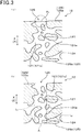
- the pore 121 includes an opening end 126 which is opened at the passage surface 125.
- the pore diameter in the opening end 126 is an opening diameter A 1
- the opening diameter A 1 is expressed by a diameter of a circle being inscribed to the opening end 126 in the cross-section of the partition 12 sectioned along the wall thickness direction.
- a diameter of the inscribed circle is referred to as an equivalent circle diameter.
- the partition 12 includes the opening end 126 of which the opening diameter A 1 is 50 ⁇ m or larger. That is, the partition 12 includes the opening end 126 that satisfies a condition of A 1 ⁇ 50 ⁇ m.
- the partition 12 includes a narrow part 127 in a region A having a predetermined relation with the opening end 126, in which the narrow part has the pore diameter of 5 ⁇ m or more and the pore diameter becomes the minimum in the region A.
- the narrow part 127 is a pore part positioned between the pore walls 124 of the partitions 12 in the region A. That is, the narrow part 127 is a pore part of which the pore diameter is 5 ⁇ m or more and is the minimum in the region A.
- the narrow part 127 serves as a constriction part of the pore in which the pore diameter thereof is significantly reduced compared to a surrounding portion.
- the pore diameter A 2 of the narrow part 127 is expressed by an equivalent circle diameter.
- the pore diameter A 2 (unit: ⁇ m) at the narrow part 127 of the pore 121 is 6% or more of the opening diameter A 1 and less than or equal to 20% of the opening diameter A 1 .
- the pore diameter A 2 of the narrow part 127 satisfies a condition 6% ⁇ A 2 / A 1 x 100 ⁇ 20%.
- the pore diameter A 2 is 6% or more and 20% or less of the opening diameter A 1 , whereby the HC removal ratio of the HC purifying catalyst is higher. This is because a thickness difference of the catalyst layer 17 is formed around the narrow part 127 and the HC having faster diffusion rate is sufficiently removed at a portion having large thickness.
- a method of forming the catalyst layer 17 is not specifically limited. However, for example, a method is generally used in which a fluid containing a catalyst such as noble metal is impregnated and baked on the partition 12. The fluid is, for example, a liquid such as a catalytic slurry.
- a portion having a larger thickness of the catalyst layer 17 is formed around the narrow part 127 with a catalyst carrying method which is generally used, and the HC removal ratio becomes higher.
- the pore diameter of the narrow part 127 is set to be 5 ⁇ m or more is that a portion having no catalyst such as HC purifying catalyst is formed around the narrow part 127 if the pore diameter of the narrow part 127 is less than 5 ⁇ m.
- the catalyst is carried using the catalytic slurry as described above, but the catalytic slurry cannot pass through the narrow portion 127 of which the pore diameter is less than 5 ⁇ m.
- a method for carrying the catalyst for example, a method in which a catalytic slurry flows from the cell 13 to be impregnated in the partition 12, and a method in which the catalytic slurry is impregnated in the partition 12 by suctioning the exhaust gas purifying filter 1 after the catalytic slurry flows into the exhaust gas purifying filter 1 from the cell 13 may be considered, but none of these methods allows the catalytic slurry to pass through the narrow part 127 of which the pore diameter is less than 5 ⁇ m. As a result, as described above, a portion is produced where no catalyst is carried. Hence, the pore diameter of the narrow part 127 is 5 ⁇ m or more.
- the narrow part 127 is in a region A of the partition 12 between virtual vertical lines L 1 and L 2 extending from both ends of the opening end 126 to the passage surface 125.
- the region A in which the passage surface 125 facing the first cell 131 is defined as a first passage surface 125a, and the passage surface 125 facing the second cell 132 is defined as a second passage 125b will be described as follows.
- the opening end 126 is an end portion of the pore 121 opened at at least the first passage 125a and the second passage 125b.
- the opening end 126 may preferably be an end portion of the communicating pores 121c.
- a predetermined region A is present on a cross-section along the wall thickness direction X, Z of the partition 12.
- the region A is positioned between a pair of virtual lines L 1 and L 2 extending from opposing sides of the opening end 126 to the passage surface 125 positioned opposite to the opening end 126 along the wall thickness direction.
- the virtual lines L 1 and L 2 each extend from either side of the opening end 126 to a passage surface (e.g.
- second passage surface 125b opposite to a passage surface where the opening end 126 is present (e.g. first passage surface 125a) along the wall thickness direction X, Z.
- the region A is in the partition 12 and for example, is a region surrounded by a dotted line shown in Fig.3 (b) .
- the both sides of the opening end 126 are end portions in a direction (e.g. a direction orthogonal to the wall thickness direction) along the passage surface 125.
- the virtual lines L 1 and L 2 are literally virtual lines and identify the region A.
- the virtual lines L 1 and L 2 are not actually drawn on the exhaust purifying filter 1, and the drawing of a range of the region A is not necessary.
- the pore diameter A 2 and the opening diameter A 1 of the narrow part 127 satisfy conditions A 1 ⁇ 50 ⁇ m, A 2 ⁇ 5 ⁇ m, 6% ⁇ A 2 /A 1 x 100 ⁇ 20% in the region A.
- the partition 12 may include a single region A or a plurality of regions A which satisfy these conditions. As many regions A as possible may preferably be present. In this case, with the HC purifying catalyst being carried, since many portions of the catalyst layer 17 having larger thickness are formed around the narrow portion 127, the HC purifying performance is further improved.
- the reason for focusing on a relationship between the opening end 126 and the narrow portion 127 in the region A is as follows.
- a method of carrying the catalyst by using the catalytic slurry generally a method in which the catalytic slurry flows into the exhaust gas purifying filter 1 by pressurizing, or a method of suctioning the exhaust gas purifying filter 1 in which the catalytic slurry is impregnated, may be employed.
- the catalytic slurry flows into the pore 121 such as the communicating pores from the opening end 126 with a pressure produced in the pressurization or suction and a pressure difference between the opening end and a termination end as a driving force.
- the catalytic slurry tends to pass through the shortest passage in a plurality of passages formed by, for example, the communicating pores, through which the catalytic slurry passes.
- the catalyst slurry flowing from the opening end 126 forms a catalyst layer 17 having a larger thickness at a portion at which the passage resistance is high (i.e. narrow portion 127). Therefore, the relationship between the opening end 126 and the narrow part 127 in the region A is important.
- the above-described terminal end is a portion where the communicating pores is opened to the passage surface 125, and is an opening portion opposite to the opening end 127. In the case where the opening end 126 is an input side of the catalytic slurry, the terminal end is a output side, or in the case where the terminal end is an input side of the catalytic slurry, the opening end 126 is the output side.
- the exhaust gas purifying filter 1 is formed to have a porosity ranging from 50% to 70%, and an average pore diameter ranging from 10 ⁇ m to 30 ⁇ m.
- the exhaust gas purifying filter has many communicating pores. As described above, since most of the communicating pores are mutually connected, as shown in Fig.3(a) and Fig.3(b) , the opening end 126 and the narrow part 127 are likely to be connected by the pore 121. In other words, a fluid passage is formed by the pore 121 that communicates between the opening end 126 and the narrow part 127.
- the passage resistance becomes high at the narrow part 127 when the fluid flows through the above-described passage.
- the catalyst layer 17 is readily carried with a large thickness at at least a localized portion around the narrow part 127.
- a portion where the catalyst layer 17 has a large thickness is readily formed around the narrow portion 127. Since the higher the porosity being set, the more readily the opening end 126 and the narrow part 127 are connected by the pore 121, the above-mentioned tendency is remarkable. Accordingly, a portion between the opening end 126 and the narrow part 127 may preferably be communicated by the pore 121.
- FIG 3 (b) illustrates a case where the opening end 126 and the narrow part 127 are communicated by a passage formed by the pore 121 existing in the region A, but the opening end 126 and the narrow part 127 may be communicated by a passage outside the region A. Even in this case, a portion where the catalyst layer 17 has a large thickness can readily be formed around the narrow portion 127.
- pores 121 having various pore diameters are present.
- the HC purifying catalyst tends to be carried by the pores 121 with the same amount of the HC purifying catalyst.
- the thickness of the catalyst layer 17 at the pore wall surface 124a becomes larger.
- the region having large thickness of the catalyst layer 17 becomes larger.
- the HC purifying performance is more improved.
- the pore volume ratio where pore diameter measured based on the mercury penetration method is less than or equal to 11 ⁇ m may preferably be 1.5% or more, more preferably be 3% or more, and further more preferably be 4% or more.
- the pore volume ratio refers to the ratio of pore volume having a predetermined pore diameter to the whole pore volume, which is calculated by the pore diameter distribution measured in accordance with the mercury penetration method as shown in the experiment example.
- the pore volume ratio where the pore diameter is 11 ⁇ m or less increases, the passage resistance becomes high and causes an increase in the pressure loss.
- the pore volume ratio where the pore diameter is 11 ⁇ m or less may preferably be 20% or less.
- a catalyst layer 17 is formed, for example.
- the supported amount of the catalyst layer 17 may preferably be 30g/L or more, or less than 80g/L.
- the pores 121 in the partition 12 can be prevented from being crushed by the catalyst layer 17.
- the carrying amount of the catalyst layer 17 may preferably be 80g /L or more, and less than or equal to 150g/L. In this case, since the contact frequency between the gas component and the catalyst component is increased, the purifying performance for the gas component is improved.
- the catalyst layer 17 formed around the narrow part 127 may preferably have a thickness difference between portions in the opposing sides of the narrow part 127. In this case, a portion having larger thickness and a portion having smaller thickness are present in the opposing sides of the narrow part 127. Then, HC having a faster diffusion rate is effectively removed at the portion having the larger thickness.
- the portions having a larger thickness and a smaller thickness can be determined based on a predetermined region surrounding the center of the narrow part 127.
- this predetermined region is referred to as a narrow region.
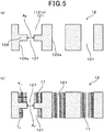
- the range of the narrow region 12A will be detailed in the experiment example section. As shown in Fig. 4 (a) and Fig.4 (b) , in the cross-section of the partition 12, the narrow region 12A is present, which surrounds the center 127a of the narrow part 127.
- the center 127a of the narrow part 127 is the center of the inscribed circuit of the narrow part 127.
- portions having a large thickness and portions having a small thickness may be present, where the boundary thereof is the center of the narrow part 127, extending in a direction along a pass positioned between the pore walls 124 where the exhaust gas G flows.
- the direction along a pass positioned between the pore walls 124 where the exhaust gas G flows refers to a direction orthogonal to the normal direction of the pore wall surface 124a.
- the thickness T 1 of the catalyst layer 17 in the large thickness side is the maximum thickness in the narrow region 12A.
- the thickness T 2 of the catalyst layer 17 in the small thickness side is the minimum thickness in the narrow region 12A.
- the thickness of the catalyst layer 17 in the pore wall 124a refers to a thickness of the catalyst layer 17 with respect to the normal direction of the pore wall surface 124a.
- the portions corresponding to the thickness T 1 and the thickness T 2 are at mutually opposite positions across the center of the narrow part 127.
- the portion having a large thickness and the portion having a small thickness of the catalyst layer 17 in the narrow region 12A, which surround the center 127a of the narrow part 127 can be observed by, for example, a scanning electron microscope.
- a condition T 2 > 0 may be satisfied, and more preferably, a condition T 1 >0 may be satisfied.
- a condition T 2 /T 1 may preferably be less than or equal to 0.6. In this case, HC purifying performance is further improved. Considering further improvement of the HC purifying performance, the condition T 2 /T 1 may preferably be less than or equal 0.5, and more preferably, the condition T 2 /T 1 may be less than or equal to 0.4.
- the exhaust gas purifying filter 1 is produced in the following manner. Firstly, a body containing a raw material for forming cordierite is produced.
- the body is prepared to have cordierite composition containing silica, talc, aluminum hydroxide and the like, and a binder such as methyl cellulose, a pore forming material such as graphite, lubricating oil and water are appropriately added and mixed, thereby producing the body.
- alumina and kaolin may be added to produce the cordierite composition.
- porous silica can be utilized.
- silica and talc can be a pore forming material 101 which is a raw material for forming the pore.
- the pore forming material 101 produces a liquid phase component during the baking process, thereby forming the pores 121.
- aluminum hydroxide, alumina and kaolin can be an aggregate raw material 102.
- the aggregate raw material 102 refers to a material for forming portions made of ceramics other than the pore 121.
- the honeycomb structure part 10 is formed.
- the honeycomb structure part 10 is constituted of the outer skin 11, the partition 12 and the cell 13.
- the opening sealed portion 16 is formed after or before baking the honeycomb structure part 10. That is, a slurry for forming the opening sealed portion 16 is used to alternately seal the end surface of the cell 13 in the molded body of the honeycomb structure part 10 before or after being baked, and bake them, thereby forming the opening sealed portion 16.
- the catalyst layer 17 is formed for the honeycomb structure part 10 before forming the opening sealed portion 16 or the honeycomb structure part 10 after forming the opening sealed portion 16.
- the catalyst layer 17 is formed by impregnating a catalytic slurry containing noble metal, alumina and co-catalyst, and firing the solid component of the slurry.
- a vacuuming can be performed.
- the partition 12 since the partition 12 satisfies conditions of the opening diameter A 1 ⁇ 50 ⁇ m, 6% ⁇ A 2 /A 1 x 100 ⁇ 20%, the passage resistance for the catalytic slurry becomes high at the narrow part 127.
- the thickness difference of the catalyst layer 17 is formed around the narrow part 127.
- HC is effectively removed at a portion having a large thickness of the catalyst layer.
- the pore forming material 101 and the aggregate raw material 102 may be arranged in patterns A to E shown in Fig. 6 .
- Pattern A shows a case where the pore forming material 101 has substantially the same particle diameter and the pore forming material 101a having large particle diameter are positioned close to each other.
- the pattern B shows a case where the pore forming materials 101a having large particle diameter touch with each other and the pore forming material 101b having small particle diameter touches with the pore forming material 101a having large particle diameter.
- the pattern C shows a case where the pore forming material 101 has substantially the same particle diameter and many pore forming material 101a having large particle diameter touch each other.
- the pattern D shows a case where the aggregate raw material 102a having large particle diameter touches each other and the pore forming material 101a having large particle diameter touches with each aggregate raw material 102a.
- the pattern E shows a case where the aggregate raw material 102b having small particle diameter are arranged between the pore forming material 101a having large particle diameter.
- the size of the narrow part 127 will be as follows.
- the pore forming material 101 touches each other as illustrated by the patterns A to C, the narrow part 127 is expanded.
- the pore forming material 101 and the aggregate raw material 102 are touched each other, and the narrow part 172 can be prevented from being expanded.
- the pattern D a mid-sized narrow part is formed
- the pattern E a small-sized narrow part is formed. Therefore, the touching patterns between the pore forming material 101 and the aggregate raw material 102 are controlled, whereby the size of the narrow part can be adjusted.
- the pore forming material 101 and the aggregate raw material 102 which have mutually opposite polarity of charges, that is, either positive or negative charge, can be utilized.
- the pore diameter A 2 can be adjusted to be within the above-described range. Note that charges may be applied to whole pore forming material 101 and whole aggregate raw material 102 used for the manufacturing, or may be applied to a part of pore forming material 101 and a part of aggregate raw material 102 used for the manufacturing.
- an anionic dispersant and a cationic dispersant can be utilized.
- the pore forming material 101 and the dispersant may be mixed in advance, and the aggregate raw material 102 and the dispersant may be mixed in advance.
- mixing respective materials 101 and 102 with corresponding dispersant is referred to as premixing.
- dispersant is adhered to the respective materials 101 and 102, thereby making the respective materials charged with opposite polarities, that is, positive charge and negative charge.
- the pore forming material 101 with the dispersant adhered thereto and the aggregate raw material 102 with the dispersant adhere thereto are further mixed.
- the communication properties of the pore 121 may be degraded.
- the mixing period should be appropriately adjusted.
- the particle diameter of the aggregate raw material 102 in the vicinity of the pore forming material 101 is large, the communication properties of the pore 121 may be degraded.
- the ratio of the particle diameter between the pore forming material 101 and the aggregate raw material 102 may preferably be adjusted.
- the opening diameter A 1 ( ⁇ m) and the pore diameter A 2 can be controlled by adjusting the ratio of the particle diameter between the pore forming material 101 and the aggregate raw material 102, type of dispersant, an amount of addition of dispersant, the mixing period, the number of rotations in the extrusion, drying period of the body and the like. As a result, a condition of A 2 / A 1 x 100 can be adjusted to be within a predetermined range while maintaining A 1 to be larger than or equal to a predetermined value.
- FIG.7 a partition 92 of the exhaust gas filter according to the present embodiment is illustrated.
- Fig.7 (a) and Fig.7 (b) schematically show communicating pores in which the communicating pores of the partition 92 (i.e. pores 911 and 912) are simplified.
- Fig.7(a) and Fig.7(b) in the partition 92 of the exhaust gas filter, various pores 911 and 912 having different pore diameters are formed.
- the pores 911 and 912 will be described differentiating them into the pore 911 having larger pore diameter and the pore 912 having small diameter.
- the thickness of the catalyst layer 97 is small.
- HC having high diffusion rate in the catalyst layer 97 reacts with catalyst insufficiently and passes through the catalyst layer 97.
- the thickness of the catalyst layer 97 of the large-sized pore 911 becomes larger, but the small-sized pore 912 is closed by the catalyst layer 77.
- small-sized pores 912 having high collection efficiency for PM are closed, the collection efficiency of the exhaust gas purifying filter is lowered. Further, the pressure loss increases.
- a plurality of exhaust gas purifying filters 1 having different values of A 2 /A 1 x 100 as shown in table 1 are produced.
- the catalyst layer 17 containing HC purifying catalyst is formed in the partition 12, and the HC removal ratio and the pressure loss are compared and evaluated.
- the exhaust gas purifying filter 1 is formed in a cylindrical shape in which the diameter is 118 mm, the length in the axial direction Y is 122 mm, containing cordierite as a major component.
- the exhaust gas purifying filter 1 has a cross-sectional shape of the cell 13 along a direction orthogonal to the axial direction Y which is rectangular.
- the cell density is 300 cpsi, and the thickness of the partition 12 is 0.220mm.
- the amount of catalyst layer 17 is 65g/L.
- silica, talc and aluminum hydroxide are prepared as a material for forming the cordierite.
- Silica and talc are the pore forming material 101
- aluminum hydroxide is aggregate forming material.
- silica, talc and anionic dispersant are mixed with water and stirred for one to two hours, thereby obtaining a first mixture.
- An amount of addition of anionic dispersant is 2-15 wt% with respect to a total amount 100 wt% of silica and talc.
- An amount of addition of water is equivalent to a half of the required amount for producing the body.
- the anionic dispersant is Nopcos Perth 44C manufactured by Sanyo Chemical Industries, Ltd.
- aluminum hydroxide, a cationic dispersant and water are mixed and stirred for one to two hours, thereby obtaining a second mixture.
- anionic dispersant is 2-15 wt% with respect to a total amount 100 wt% of silica and talc.
- An amount of addition of water is equivalent to a half of the required amount for producing the body.
- the cationic dispersant is Nopcos Perth 092 manufactured by Sanyo Chemical Industries, Ltd.
- the dispersant is polyoxyethylene polyoxypropylene glyceryl ether in which the average molecular amount is 4550.
- the binder is methyl cellulose.
- the body is extrusion-molded and fired at 140 degree C, and the opening sealed portion 16 is formed, thereby obtaining the exhaust gas purifying filter 1.
- the catalyst layer 17 is formed in the exhaust gas purifying filter 1 with a method similar to that of the first embodiment. According to the present example, an amount of addition of the anionic dispersant, an amount of addition of the cationic dispersant, stirring time and mixing time are changed, thereby obtaining 13 types of exhaust gas purifying filter 1 as shown in table 1.
- An exhaust gas purifying filter 1 is measured in a state where the catalyst layer 17 is not formed, that is, before forming the catalyst layer.
- the opening diameter A 1 and the pore diameter A 2 of the narrow part 137 described in the first embodiment are measured based on a scanning electron microscopic image of a cross-section of the partition 12 of the exhaust gas purifying filter 1.
- the scanning electron microscope is hereinafter appropriately referred to as an SEM.
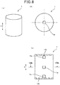
- the observation points of the SEM image are shown in Fig.8 (a) to Fig.8 (c) .
- the observation points are three points with respect to the axial direction Y passing through the center portion in the diameter of the exhaust gas purifying filter 1, which are a center portion 1a, a portion 1b immediately inside the opening sealed portion 16 of an inflow end surface 14 side and a portion 1c immediately inside the opening sealed portion 16 of an outflow end surface 15 side.
- an S-3400N manufactured by Hitachi High-Technologies Corporation is utilized under a condition where acceleration voltage: 15.0 kV, magnification: 300 to obtain the SEM image of the cross-section of the partition.
- the SEM image is a backscattered electron image. An example thereof will be shown in Fig.9 (a).
- Fig.9 (a) is a SEM image showing a cross-section of the partition of the exhaust gas purifying filter 1 before forming the catalyst layer (i.e. base material). As shown in Fig.9(a) , many pores 121 are formed in the partition 12, and most of them are communicating pores 121c.
- Fig.9 (a) illustrates the opening end 126 having a diameter of 50 ⁇ m or larger at two portions (i.e. first opening end 126a and second opening end 126b) and the diameter A 1 .
- the opening diameter A 1 of the first opening end 126a is 82.6 ⁇ m and the opening diameter A 1 of the second opening end 126b is 177.4 ⁇ m.
- Fig.9 (b) illustrates a region A in a range having the above-described relationship with the first opening end 126a, which is extracted from the SEM image shown in Fig.9 (a) .
- Fig.9 (b) a position of the narrow part 127 and the pore diameter A 2 thereof are shown, where the pore diameter A 2 is 8.4 ⁇ m.
- Fig.9 (c) illustrates a region A having the above-described relationship with the second opening end 126b, where the region A is extracted from the SEM image shown in Fig.9 (a) .
- Fig.9 (c) a position of the narrow part 127 and the pore diameter A 2 thereof are shown, where the pore diameter A 2 is 7.3 ⁇ m. Note that circles shown in Fig.9 (a) to Fig.9 (c) show inscribed circles.
- the opening diameter A 1 and the pore diameter A 2 of the respective exhaust gas purifying filter 1 shown in table 1 are measured.
- a 2 /A 1 x100 is calculated.
- the values of the opening diameter A 1 and A 2 /A 1 x100 are shown in table 1. Note that a plurality of values corresponding to the opening diameter A 1 and A 2 /A 1 x100 are obtained from three SEM observation points, but table 1 shows their arithmetic mean value.
- the exhaust gas purifying filter 1 is measured in a state where the catalyst layer 17 is not formed, that is, the exhaust gas purifying filter 1 before forming the catalyst layer is measured.
- the measurement samples are collected from the partition 12 of the exhaust gas purifying filter 1, and the porosity and the average pore diameter are measured with a mercury porosimeter using the mercury penetration method.
- the measurement samples are collected at three points which are the same as the observation point of the SEM image.
- the measurement sample has a substantially rectangular parallelepiped shape in which the length in the axial direction Y is 1cm, the thickness in the wall thickness direction is 1cm, the length orthogonal to the axial direction and the wall thickness direction is 1cm.
- the measurement result is the arithmetic mean value of the porosity and the average pore diameter of the respective samples.
- the average pore diameter is also referred to as average pore size.
- an AutoPore IV 9500 manufactured by SHIMADZU CORPORATION is used for the mercury porosimeter.
- the measurement sample is accommodated in a measurement cell of the mercury porosimeter and the pressure in the measurement cell is reduced. Thereafter, mercury is introduced in the measurement cell, and the pore diameter and the pore volume are measured in accordance with the pressure when pressurized and the mercury volume introduced in the pore of the measurement sample.
- the pore diameter and the pore volume are measured in a pressure range from 0.5 psia to 20000 psia. Note that 0.5 psia corresponds to 0.35x10 -3 kg/mm 2 , and 20000 psia corresponds to 14kg/mm 2 .
- the range of the pore diameter corresponding to this pressure range is 0.01 ⁇ m to 420 ⁇ m.
- a contact angle 140 degrees and a surface tension 480 dyn/cm are used.
- the average pore diameter refers to a pore diameter at 50% of accumulated value of the pore volume.
- the exhaust gas purifying filter 1 is measured in a state where the catalyst layer 17 is not formed, that is, the exhaust gas purifying filter 1 before forming the catalyst layer is measured.
- a distribution of the pore diameters in each measurement sample is measured with a mercury porosimeter using the mercury penetration method. The measurement is conducted with similar method and condition for the above-described porosity and average pore diameter. With the distribution of pore diameter, a volume ratio of pore diameter having the pore diameter of less than or equal to 11 ⁇ m is calculated.
- the exhaust gas purifying filter 1 is measured in a state where the catalyst layer 17 is formed, that is, the exhaust gas purifying filter 1 after forming the catalyst layer is measured.
- the SEM image of the cross-section of the partition in the exhaust gas purifying filter 1 the thickness T 1 and T 2 described in the first embodiment is measured.
- the scanning electron microscope is hereinafter appropriately referred to as an SEM.
- the observation points of the SEM image are three points similar to those in the measurement of the opening diameter A 1 of the opening end 126 and the pore diameter A 2 of the narrow part 127.
- an S-3400N manufactured by Hitachi High-Technologies Corporation is utilized under a condition where acceleration voltage: 15.0 kV, magnification: 300 to obtain the SEM image of the cross-section of the partition.
- the SEM image is a backscattered electron image. An example thereof will be shown in Fig.10 (a).
- Fig.10 (a) is a SEM image showing a cross-section of the partition of the exhaust gas purifying filter 1 after forming the catalyst layer (i.e. base material).
- Fig.10 (a) illustrates the opening end 126 having a diameter of 50 ⁇ m or larger and the diameter A 1 . As shown in Fig.10 (a) , the opening diameter A 1 of the opening end A 1 is 68 ⁇ m.
- Fig.10 (b) illustrates a part of the region A in a range having the above-described relationship with the first opening end 126a, which is extracted from the SEM image shown in Fig.10 (b).
- Fig.10 (b) illustrates a position of the narrow part 127 with the position of the inscribed circle.
- Fig.10 (c) is a SEM image showing a narrow region 12A surrounding the center 127a of the narrow part, which is extracted from the SEM image shown in Fig.9 (a) .
- Fig.10 (d) is an enlarged view of Fig.10 (c) , in which the position of the narrow part is indicated by a circle.
- the narrow region 12A is a region surrounded by a rectangle in which the center of gravity is a position of the center 127a of the narrow part shown in Fig.4 , the length in the wall thickness direction is 12.5 ⁇ m and the length in a direction orthogonal to the wall thickness direction is 27 ⁇ m.
- the thickness T 1 of the catalyst layer 17 having larger thickness and the thickness T 2 of the catalyst layer 17 having smaller thickness are measured. Then, the thickness ration T 2 /T 1 is measured based on these measurement values.
- the arithmetic mean value of the calculation values at the above-described three points is shown in table 1.
- the circles shown in Fig.10 (a) to Fig.10 (c) are inscribed circles.
- the reason for focusing on the narrow region 12A surrounded by the rectangle having the above-described predetermined dimension is that the narrow region 12A has an apparent thickness difference between T 1 and T 2 .
- the exhaust gas purifying filter 1 is measured in a state where the catalyst layer 17 is formed, that is, the exhaust gas purifying filter 1 after forming the catalyst layer is measured.
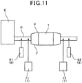
- the exhaust gas purifying filter 1 is attached inside an exhaust pipe P of a gasoline direct injection engine E of which the spec is 2.0 liters engine capacity, natural aspiration and four cylinders.
- a ceramic mat (not shown) is wound around the exhaust purifying filter 1, and the exhaust gas purifying filter 1 is inserted into a filter case C.
- the filter case C is coupled to the exhaust pipe P of the engine E via a fitting cone, and exhaust gas is made to flow into the exhaust gas purifying filter 1 from the engine E.
- A/F i.e.
- air fuel ratio: air/fuel value is maintained at 14.4 while monitoring the A/F by an A/F sensor 8, and a gas concentration meter 7 measures the HC concentration in the exhaust gas under a condition where an intake air quantity is 10g/s, and the engine speed of the engine E is 1500 rpm.
- a first gas concentration meter 71 for measuring the HC concentration at an inlet side positioned before the exhaust gas flows into the exhaust gas purifying filter 1 and a second gas concentration meter 72 for measuring the HC concentration at an outlet side where the exhaust gas flows out from the exhaust gas purifying filter 1 are used.
- the first gas concentration meter 71 and the second gas concentration meter are a MEXA-7500 manufactured by HORIBA, Ltd.
- a value of A/F: 14.4 refers to an A/F value frequently appears during the engine start operation at the WLTC mode travelling.
- the condition of the intake air quantity 10g/s and the engine speed 1500 rpm is determined simulating a low temperature environment when the engine starts, which is low temperature region, for example, and the exhaust gas temperature is 450 degree C or below.
- the HC removal ratio is calculated from the inlet side HC concentration measured by the first gas concentration meter 71 and the outlet side HC concentration measured by the second gas concentration meter 72 based on the following equation.
- HC removal ratio 100 ⁇ inlet side HC concentration ⁇ outlet side HC concentration / inlet side HC concentration
- the exhaust gas purifying filter 1 is measured in a state where the catalyst layer 17 is formed, that is, the exhaust gas purifying filter 1 after forming the catalyst layer is measured.
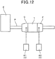
- the exhaust gas purifying filter 1 is attached inside an exhaust pipe P of a gasoline direct injection engine E of which the spec is 2.0 liters engine capacity, natural aspiration and four cylinders. Then, the exhaust gas is made to flow into the exhaust gas purifying filter 1 from the engine E. With a pressure sensor 6, pressures are measured between a front portion positioned before the exhaust gas purifying filter 1 and a back portion positioned behind the exhaust gas purifying filter 1 to obtain a difference therebetween to be the pressure loss.
- the front-back direction is a direction along which the exhaust gas flows.
- the measurement condition is that the temperature is 720 degree C, the exhaust gas flow rate is 11.0m 3 /min.
- Each measurement is performed under an initial state in which PM is not accumulated in the exhaust gas purifying filter 1.
- the pressure at the front portion is measured by a first pressure sensor 61 and the pressure at the back portion is measured by a second pressure sensor 62.
- Example 1 Average pore diameter ( ⁇ m) A 1 A 2 A 2 /A 1 x 100 Pore volume ratio (%) where pore diameter is less than or equal to 11 ⁇ m T 2 /T 1 HC removal ratio Pressure Loss ( ⁇ m) ( ⁇ m) (%) (%) (kPa)
- Example 1 64 22 82 13.5 16.5 6.3 0.36 96.2 3.8
- Example 2 64 20 131 9.4 7.2 4.1 0.14 99.1 4.5
- Example 3 64 18 113 15.8 14 19.5 0.3 97.2 3.9
- Example 4 64 20 162 17.8 11 24 0.26 97.5 4.8
- Example 5 64 18 155 14 9 13 0.28 98 3.9
- Example 6 64 18 130 8.1 6.2 3.8 0.04 91.2 4.5
- Example 7 64 18 145 26.1 18 3 0.41 90.1 3.8
- Example 8 64 18 132 26.1 19.8 26 0.42 85.2 4.9
- Comparative Example 1 64 18 142 51.1 36 1 0.73 61.1 3.6
- Comparative Example 2 64 18 90 18.9
- pores 121 are present in which the opening diameter A 1 of the opening end 126 is 50 ⁇ m or larger. Further, in the examples 1 to 8, a narrow part 127 is present in the region A having predetermined relationship with the opening end 126, where a relationship between the pore diameter A 2 and the opening diameter A 1 , i.e., A 2 /A 1 x 100 is 6% to 20%. As a result, according to the examples 1 to 8, the HC removal ratio is high.
- the thickness ratio T 2 /T 1 of the catalyst layer 17 is small.
- the pressure loss is low while exhibiting high HC removal ratio.
- the ratio A 2 /A 1 x 100 exceeds 20%, the passage resistance in the narrow part 127 becomes small. Hence, the catalyst layer 17 having large thickness is unlikely to be formed around the narrow part 127. Thus, the thickness of the catalyst layer 17 is insufficient from a viewpoint of the HC removal ratio. Accordingly, as shown in Table 1 and Fig.13 , the HC removal ratio becomes low.
- the ratio of A 2 /A 1 x 100 is required to be 20% or below in order to enhance the HC removal ratio to accomplish better HC purification performance of the exhaust purifying filter 1.
- the ratio A 2 /A 1 x 100 may preferably be 18 % or lower, and more preferably 17% or lower. From a similar point of view, the ratio A 2 /A 1 may preferably be 6% or larger.
- the ratio A 2 /A 1 x 100 may preferably be 6% or larger in order to suppress degradation of the purifying performance and an increase in the pressure loss.
- the ratio A 2 /A 1 x 100 is 6% or larger, the HC purifying performance is superior and also an effect of suppressing the pressure loss is significant.
- the pressure loss can be lower than 5kPa which is suitable for a gasoline automobile.
- the ratio A 2 /A 1 x 100 may preferably be 8% or larger which produces a more significant effect of suppressing the pressure loss.
- the HC removal ratio is high in a range from 6% to 20% of the ratio A 2 /A 1 x 100. Also, in this range, a constant region I is present where the HC removal ratio is not substantially changed even when the ratio A 2 /A 1 x 100 varies. In the constant region I, for example, since HC is sufficiently diffused inside the catalyst layer around the narrow part 127, if the amount of coating of the catalyst layer 17 is the same, the HC removal ratio is constant. On the other hand, in the case where the ratio A 2 /A 1 x 100 is less than 6% or larger than 20%, the HC removal ratio is lowered compared to a case where the ratio A 2 /A 1 x 100 ranges from 6% to 20%.
- a constant region II is present where the HC removal ratio is not substantially changed.
- the thickness of the catalyst layer 17 around the narrow part 127 is large exceeding a predetermined thickness, and a diffusion distance of HC is constant from a point of view of the gas velocity and the reaction time.
- the HC removal ratio is saturated.
- the pore volume ratio where the pore diameter is less than or equal to 11 ⁇ m may preferably be 3% or larger.
- the pore volume ratio where the pore diameter is less than or equal to 11 ⁇ m may more preferably be 4% or larger.
- the pore volume ratio when the pore volume ratio is less than or equal to 26% where the pore diameter is less than or equal to 11 ⁇ m, the HC removal ratio is enhanced. This is because clogging in the pore 121 is suppressed, whereby a portion where the exhaust gas and the catalyst are not touched or unlikely to be touched are prevented from being formed. Accordingly, in order to enhance the HC removal ratio, the pore volume ratio may preferably be less than or equal to 26% where the pore diameter is less than or equal to 11 ⁇ m. More preferably, the pore volume ratio may be less than or equal to 24% where the pore diameter is less than or equal to 11 ⁇ m, in order to further enhancing the HC removal ratio.
- the pore volume ratio when the pore volume ratio is less than or equal to 20% where the pore diameter is less than or equal to 11 ⁇ m, the pressure loss is low. This is because the number of pores having small diameters which increase the passage resistance is lowered. Therefore, from the viewpoint of reducing the pressure loss, the pore volume ratio may preferably be less than or equal to 20% where the pore diameter is less than or equal to 11 ⁇ m.
- a larger side thickness T 1 and a smaller side thickness T 2 in the thickness of the catalyst layer 17 across the narrow part 127 may preferably satisfy a relationship T 2 /T 1 ⁇ 0.6.
- the HC removal ratio tends to be increased.
- the relationship T 2 /T 1 ⁇ 0.4 may more preferably be satisfied.
- symbols same as those in the existing embodiments indicate similar constituents in the existing embodiments unless otherwise specified.
- the exhaust gas purifying filter 1 is utilized for purifying the exhaust gas of an internal combustion engine such as a diesel engine or a gasoline engine, but the exhaust gas purifying filter 1 may preferably be used for purifying an exhaust gas from the gasoline engine.
- the exhaust gas purifying filter 1 may preferably be a gasoline particulate filter.
- the gasoline particulate filter is referred to as GPF.
- the GPF is required to have not only a PM purifying performance but also a purifying performance for toxic gas using a coated purification catalyst for the toxic gas component such as HC.
- the exhaust gas purifying filter 1 is more preferably applied to an exhaust gas purifying apparatus provided with a hybrid engine and an engine controlled by an idling-stop apparatus.
- the exhaust gas purifying filter 1 as a component of the exhaust gas purifying apparatus is able to sufficiently purify HC frequently emitted from the engine with the HC catalyst carried by the exhaust gas purifying filter 1, while collecting PM with the filtering structure thereof.
Landscapes
- Chemical & Material Sciences (AREA)
- Engineering & Computer Science (AREA)
- Chemical Kinetics & Catalysis (AREA)
- Materials Engineering (AREA)
- Organic Chemistry (AREA)
- Combustion & Propulsion (AREA)
- Mechanical Engineering (AREA)
- General Engineering & Computer Science (AREA)
- Ceramic Engineering (AREA)
- Health & Medical Sciences (AREA)
- Toxicology (AREA)
- Physics & Mathematics (AREA)
- Structural Engineering (AREA)
- Geometry (AREA)
- Biomedical Technology (AREA)
- Environmental & Geological Engineering (AREA)
- Analytical Chemistry (AREA)
- General Chemical & Material Sciences (AREA)
- Oil, Petroleum & Natural Gas (AREA)
- Catalysts (AREA)
- Exhaust Gas Treatment By Means Of Catalyst (AREA)
- Exhaust Gas After Treatment (AREA)
- Nanotechnology (AREA)
- Processes For Solid Components From Exhaust (AREA)
Abstract
Description
- The present application claims the benefit of priority based on
Japanese Patent Application No. 2019-086488 filed on April 26, 2019 - The present disclosure relates to an exhaust gas purifying filter used with carrying purification catalyst.
- In an exhaust gas emitted from an internal combustion engine, such as a diesel engine and a gasoline engine, or a heat engine such as a boiler, particulate matter referred to as particulates is contained. The particulate matter is hereinafter referred to as PM. The exhaust gas purifying filter is used for collecting PM contained in the exhaust gas.
- The exhaust gas purifying filter generally includes a plurality of cells which are divided by porous partitions, and an opening sealed portion that seals one end of opposing ends of the cell. The exhaust purifying filter is required to reduce a pressure loss and collect PM contained in the exhaust gas to be in the pores of the partitions. Note that the pressure loss is sometimes referred to as P-loss.
- For example, PTL1 discloses a filter in which the porosity is from 45% to 70%, a predetermined average pore diameter difference ratio is or less than or equal to 35%, an average pore diameter is from 15µm to 30 µm, and the maximum pore diameter measured by a bubble point method is 150 µm or less. According to PTL1, by adopting the above-described configurations, a P-loss when PM is being deposited can be reduced.
- [PTL1]
Japanese patent number 4473693 - In recent years, since it is required to apply a purifying function for toxic substances such as HC using the exhaust gas purifying filter, for example, an HC purifying catalyst is carried on the exhaust gas purifying filter. Note that HC refers to generic term hydrocarbon.
- Since HC has a high diffusion rate in the catalytic layer formed after supporting the catalyst it does not sufficiently react with the catalyst and easily passes therethrough. For purifying HC, the larger the thickness of the catalytic layer, the more advantageous it is for purifying HC. However, according to a conventional exhaust gas purifying filter as disclosed by PTL1, the catalyst layer is unlikely to have a sufficiently large thickness to purify HC. Therefore, the purifying performance for HC after supporting the catalyst thereon is required to be further improved.
- The present disclosure is to provide an exhaust gas purifying filer capable of exhibiting excellent purifying performance for HC by supporting a catalyst.
- One aspect of the present disclosure is an exhaust gas purifying filter (1) used with a HC purifying catalyst carried thereon, including:
- a honeycomb structure part having a partition including numerous pores formed therein, and a plurality of cells divided by the partitions, forming a passage for an exhaust gas; and
- an opening sealed portion that alternately seals an inflow end surface or an outflow end surface of the exhaust gas in the cells,
in which - in a cross-section of the partition sectioned along a wall thickness direction, each pore is opened at a passage surface facing the cells, having an opening end of which the opening diameter is 50µm or larger;
- the partition includes a narrow part in a region positioned between a pair of virtual lines extending from both ends of the opening end to a passage surface positioned opposite to the opening end along the wall thickness direction, the narrow part having a pore diameter of 5µm or more, the pore diameter becoming a minimum in the region; and
- the pore diameter A2 at the narrow part is 6% or more and less than or equal to 20% of the opening diameter A1.
- In the cross-section of the partition in the above-described exhaust gas purifying filter, the pore diameter A2 at the narrow part is 6% or more and less than or equal to 20% of the opening diameter A1 of the pore. In such a portion around the narrow part, a catalyst layer is formed with a large thickness at at least a localized portion. In the portion of the catalyst layer having large thickness, since the contact frequency between HC and catalyst is increased, HC reacts sufficiently with the catalyst before passing through the pore. Accordingly, the exhaust gas purifying filter has a high HC removal ratio and excellent HC purifying performance.
- According to the above-described aspect, an exhaust gas purifying filter capable of exhibiting excellent HC purifying performance by supporting a catalyst thereon can be provided. Note that reference numbers in brackets in claims indicate correspondence relationship between elements and specific means described in the embodiments which will be described later, and do not limit the technical scope of the present disclosure.
-
-
Fig.1 is a perspective view showing an exhaust gas purifying filter according to a first embodiment of the present disclosure; -
Fig.2 is an enlarged cross-sectional view sectioned in the axial direction of the exhaust gas purifying filter according to the first embodiment; -
Fig.3 (a) is an enlarged cross-sectional schematic view of a partition showing an opening diameter of an opening according to the first embodiment andFig.3 (b) is an enlarged cross-sectional schematic view of a partition especially showing a region A surrounding by a virtual line according to the first embodiment; -
Fig.4 (a) is an enlarged cross-sectional schematic view of a partition showing a narrow part according to the first embodiment andFig.4 (b) is an enlarged cross-sectional schematic view of a partition showing a narrow part in which a HC purifying catalyst is carried according to the first embodiment; -
Fig.5 (a) is a schematic view showing a narrow part which is simplified in a cross-section of the partition according to the first embodiment andFig.5 (b) is a schematic view showing a simplified narrow part in a cross-section of the partition in which a HC purifying catalyst is carried according to the first embodiment; -
Fig.6 is a schematic view showing an arrangement pattern of particle material according to the first embodiment; -
Fig.7 (a) is a schematic view simply showing a cross-section of a partition in which a small amount of HC purifying catalyst is carried according to a comparative example 1 andFig.7 (b) is a schematic view simply showing a cross-section of a partition in which a large amount of HC purifying catalyst is carried according to a comparative example 1; -
Fig.8 (a) is a schematic view showing an outline of an exhaust gas purifying filter according to an experiment example 1,Fig.8 (b) is a schematic view showing a sampling position of a measurement sample with respect to the radial direction of the exhaust gas purifying filter according to the experiment example 1 (i.e. cross-sectional view ofFig.8 (c) sectioned at line VIIIb-VIIIb) andFig.8 (c) is a schematic view showing a sampling position of a measurement sample with respect to the axial direction and the radial direction of the exhaust gas purifying filter according to the experiment example 1. -
Fig.9 (a) is a photographic image showing an example of a scanning electron microscopic image of a cross-sectioned partition according to the experiment example 1,Fig.9 (b) is a photographic image showing a predetermined region A corresponding to a first opening end according to the experiment example 1 andFig.9 (c) is a photographic image showing a predetermined region A corresponding to a second opening end according to the experiment example 1; -
Fig.10 (a) is a photographic image showing an example of a scanning electron microscopic image of a cross-sectioned partition where a catalyst layer is formed according to the experiment example 1,Fig.10 (b) is a photographic image showing a part ofFig.10 (a), Fig.10 (c) a photographic image showing a part ofFig.10 (b) and Fig.10 (d) is an enlarged view ofFig.10 (c) ; -
Fig.11 is a schematic view showing a configuration of measurement equipment for measuring HC removal ratio according to the experiment example 1; -
Fig.12 is a schematic view showing a configuration of measurement equipment for measuring a pressure loss; -
Fig.13 is a graph showing a relationship between a ratio of an opening diameter A1 to a pore diameter A2 and the HC removal ratio according to the experiment example 1; -
Fig.14 is a graph showing a relationship between a pore volume ratio in which pore diameter is less than or equal to 11µm and the HC removal ratio; and -
Fig.15 is a graph showing a relationship between a pore volume ratio in which pore diameter is less than or equal to 11µm and the pressure loss. - With reference to
Figs.1 to 6 , an embodiment of an exhaust gas purifyingfilter 1 will be described. As exemplified inFigs.1 to3, the exhaust gas purifyingfilter 1 includeshoneycomb structure part 10 and an opening sealedportion 16. Thehoneycomb structure part 10 is constituted of, for example, ceramic such as cordierite and includes anouter skin 11,partition 12 and acell 13. - As shown in
Figs.1 and 2 , theouter skin 11 is formed as a cylindrical body. The specific shape of theouter skin 11 is a cylindrical shape in which the cross-sectional shape sectioned along a direction orthogonal to the axial direction is a circular shape, but theouter skin 11 may be formed in a polygonal shape in which the cross-sectional shape is a polygon such as a square. According to the present embodiment, the axial direction Y of theouter skin 11 having the cylindrical shape is defined as an axial direction Y of the exhaust gas purifyingfilter 1. Note that each arrow shown inFig.2 indicates a direction along which the exhaust gas G flows in the case where the exhaust gas purifyingfilter 1 is disposed in a passage such as the exhaust gas pipe where exhaust gas G flows through. - The
partition 12 divides a region inside theouter skin 11 into a plurality ofcells 13. The partitions 21 are generally referred to as cell walls. Thepartition 12 is provided in a lattice shape. The exhaust gas purifyingfilter 1 is formed as a porous body, andnumerous pores 121 are formed in thepartition 12 as shown inFig.3 . Hence, the exhaustgas purifying filter 1 is able to cause PM contained in the exhaust gas G to be deposited on a surface of thepartition 12 and in thepores 121, thereby collecting it. Thepores 121 are sometimes generally referred to as holes. PM refers to fine particles, called particulate substances, particulate matter or particulates. Theouter skin 11 and thepartition 12 are integrally formed. - As shown in
Figs.1 and 2 , the exhaustgas purifying filter 1 includes a plurality ofcells 13. Thecells 13 are surrounded bypartitions 12 to form a passage for the exhaust gas G. An extending direction of thecells 13 usually matches the axial direction Y. - As shown in
Fig.1 , a cell shape at a cross-section sectioned along a direction orthogonal to the axial direction Y is, for example, a square shape, but it is not limited thereto. The cell shape may be a polygonal shape such as a triangle shape, a square shape and a hexagonal shape, or a circular shape. - The exhaust
gas purifying filter 1 is used when a HC purifying catalyst is supported thereon. Hence, the exhaustgas purifying filter 1 before supporting the catalyst can be a base material for supporting the HC purifying catalyst. The HC purifying catalyst is carried by at least thepartition 12. The exhaustgas purifying filter 1 may have a support surface for supporting the HC purifying catalyst in thepartition 12. The carrying surface is, for example, apassage surface 125 and apore wall surface 124a as shown inFigs.2 to 5 . The HC purifying catalyst is carried by thepartition 12 as acatalyst layer 17. - The exhaust
gas purifying filter 1 is, for example, a cylinder body such as a columnar body and the dimension thereof may be appropriately changed. The exhaustgas purifying filter 1 includes aninflow end surface 14 and anoutflow end surface 15 at both ends thereof in the axial direction Y. Theinflow end surface 14 serves as an end surface where the exhaust gas G flows in under a state where the exhaustgas purifying filter 1 is disposed in a flow of the exhaust gas G, and theoutflow end surface 15 serves as an end surface where the exhaust gas G flows out. In a state where the exhaustgas purifying filter 1 is not disposed in the flow of the exhaust gas G, theinflow end surface 14 and theoutflow end surface 15 refer to relative surfaces in the axial direction Y of the exhaustgas purifying filer 1. That is, when either one end surface is aninflow end surface 12, the other is theoutflow end surface 15. For example, theinflow end surface 14 may be referred to as a first end surface and theoutflow end surface 15 may be referred to as a second end surface. - The exhaust
gas purifying filter 1 includes an opening sealedportion 16. The opening sealedportion 16 alternately seals theinflow end surface 14 or theoutflow end surface 15, for example. The opening sealedportion 16 is formed of ceramic such as cordierite, but may be formed of other material. InFig.2 , a plug-shaped opening sealedportion 16 is formed, but the shape of the opening sealedportion 16 is not limited to any particular shape as long as theinflow end surface 14 or theoutflow end surface 15 is sealed. Although illustration of constituents are omitted, for example, a part of the partitions may be deformed in theinflow end surface 14 or theoutflow end surface 15, whereby the opening sealedportion 16 can be formed. In this case, since part of the partitions forms the opening sealedportion 16, thepartition 12 and the opening sealedportion 16 are integrally and continuously formed. - As
cells 13, thecells 13 include, for example,first cells 131 andsecond cells 132. As shown inFig.2 , thefirst cells 131 are open, for example, at theinflow end surface 14 as an inflow side of the exhaust gas, and are sealed at theoutflow end surface 15 by the opening sealedportion 16. Thesecond cells 132 are open, for example, at theoutflow end surface 15 as an outflow side of the exhaust gas, and are sealed at theinflow end surface 14 by the opening sealedportion 16. - The
first cells 131 and thesecond cells 132 are alternately arranged in parallel, for example, to be positioned adjacently with each other in the lateral direction X orthogonal to the axial direction and also in the vertical direction Z orthogonal to both the axial direction X and the lateral direction X. In other words, when viewing theinflow end surface 14 or theoutflow end surface 15 of the exhaustgas purifying filter 1 in the axial direction Y, thefirst cells 131 and thesecond cells 132 are arranged, for example, to be in a checkered pattern. - The
partition 12 separates the adjacently positionedfirst cell 131 andsecond cell 132. In thepartition 12, as shown inFig.3 (a) ,numerous pores 121 are formed by apore wall 124. Thepore 121 includes communicatingpores 121c that communicates between thefirst cell 131 and thesecond cell 132, and non-communicating pores(not shown) that does not communicate between thefirst cell 131 and thesecond cell 132. As shown in an experiment example, the communicatingpores 121c can be observed by an electron microscopic inspection of the cross-section of the partition. InFig.3 (a) , thepores 121 are simply illustrated as a two- dimensional image. However, most of thepores 121 may three-dimensionally intersect each other. Thepore 121 serves as a passage of the exhaust gas G in thepartition 12. The exhaust gas G passes through thepore 121, thereby collecting the PM contained in the exhaust gas G on thepore wall surface 124a. Thepore wall surface 124a is a portion where thepore wall 124 faces thepore 121. Also, the HC purifying catalyst is carried on thepore wall 124, whereby toxic gas components such as HC contained in the exhaust gas G are purified by the HC purifying catalyst. Thecell 13 serves as a passage of the exhaust gas G similar to thepore 121, where the PM is collected on apassage surface 125 of thepartition 12, and the HC purifying catalyst is carried on thepassage surface 125, thereby purifying the toxic gas component on thepassage surface 125 as well. Thepassage surface 125 is a portion where thepartition 12 faces thecell 13. - The number of communicating pores is appropriately increased, whereby a reduction of the pressure loss and an improvement of the PM collection ratio can be achieved. The number of communicating pores, and the shape thereof can be adjusted with, for example, a porosity and an average pore diameter as an index. In view of appropriately increasing the number of communicating pores and securing required strength when assembling the exhaust
gas purifying filter 1, the porosity may preferably be from 50% to 70%, more preferably be from 53% to 67%, and further more preferably be from 55% to 65%. From a similar point of view, the average pore diameter may preferably be from 12µm to 24µm, more preferably be from 13µm to 23µm, and further more preferably be from 14µm to 22µm. The porosity and the average pore diameter are measured based on the theory of mercury penetration method as shown in the experiment example. - As shown in
Fig.4 (b) , for example, thecatalyst layer 17 is formed on thepore wall surface 124a of thepartition 12. Thecatalyst layer 17 may continuously formed or dis-continuously formed. Thecatalyst layer 17 is formed on thepassage surface 125 of thepartition 12 as well. - The
catalyst layer 17 contains HC purifying catalyst. As the purifying catalyst, a three-way catalyst composed of noble metals such as Pt, Rh, Pd can be utilized. In this case, the HC catalyst is capable of purifying toxic gas components such as CO and NOx in addition to the HC. Thecatalyst layer 17 may contain alumina and auxiliary catalyst. An alumina, ceria, zirconia, ceria-zirconia solid solution and the like are exemplified. - As shown in
Fig.3 (a) and Fig.3 (b) , thepore 121 includes anopening end 126 which is opened at thepassage surface 125. The pore diameter in the openingend 126 is an opening diameter A1, and the opening diameter A1 is expressed by a diameter of a circle being inscribed to the openingend 126 in the cross-section of thepartition 12 sectioned along the wall thickness direction. A diameter of the inscribed circle is referred to as an equivalent circle diameter. Thepartition 12 includes the openingend 126 of which the opening diameter A1 is 50µm or larger. That is, thepartition 12 includes the openingend 126 that satisfies a condition of A1 ≥ 50µm. - Further, the
partition 12 includes anarrow part 127 in a region A having a predetermined relation with the openingend 126, in which the narrow part has the pore diameter of 5µm or more and the pore diameter becomes the minimum in the region A. Thenarrow part 127 is a pore part positioned between thepore walls 124 of thepartitions 12 in the region A. That is, thenarrow part 127 is a pore part of which the pore diameter is 5µm or more and is the minimum in the region A. Thenarrow part 127 serves as a constriction part of the pore in which the pore diameter thereof is significantly reduced compared to a surrounding portion. The pore diameter A2 of thenarrow part 127 is expressed by an equivalent circle diameter. The pore diameter A2 (unit: µm) at thenarrow part 127 of thepore 121 is 6% or more of the opening diameter A1 and less than or equal to 20% of the opening diameter A1. Specifically, the pore diameter A2 of thenarrow part 127 satisfies acondition 6% ≤ A2 / A1 x 100 ≤ 20%. The pore diameter A2 is 6% or more and 20% or less of the opening diameter A1, whereby the HC removal ratio of the HC purifying catalyst is higher. This is because a thickness difference of thecatalyst layer 17 is formed around thenarrow part 127 and the HC having faster diffusion rate is sufficiently removed at a portion having large thickness. Further, since the HC purifying performance can be improved without increasing an amount of the HC purifying catalyst to be carried, the pressure loss accompanied by an increase in the amount of the HC purifying catalyst supported can be prevented from increasing. A method of forming thecatalyst layer 17 is not specifically limited. However, for example, a method is generally used in which a fluid containing a catalyst such as noble metal is impregnated and baked on thepartition 12. The fluid is, for example, a liquid such as a catalytic slurry. For thepartition 12 having thenarrow part 127, for example, a portion having a larger thickness of thecatalyst layer 17 is formed around thenarrow part 127 with a catalyst carrying method which is generally used, and the HC removal ratio becomes higher. - The reason why the pore diameter of the
narrow part 127 is set to be 5µm or more is that a portion having no catalyst such as HC purifying catalyst is formed around thenarrow part 127 if the pore diameter of thenarrow part 127 is less than 5µm. Generally, the catalyst is carried using the catalytic slurry as described above, but the catalytic slurry cannot pass through thenarrow portion 127 of which the pore diameter is less than 5µm. For a method for carrying the catalyst, for example, a method in which a catalytic slurry flows from thecell 13 to be impregnated in thepartition 12, and a method in which the catalytic slurry is impregnated in thepartition 12 by suctioning the exhaustgas purifying filter 1 after the catalytic slurry flows into the exhaustgas purifying filter 1 from thecell 13 may be considered, but none of these methods allows the catalytic slurry to pass through thenarrow part 127 of which the pore diameter is less than 5µm. As a result, as described above, a portion is produced where no catalyst is carried. Hence, the pore diameter of thenarrow part 127 is 5µm or more. - The
narrow part 127 is in a region A of thepartition 12 between virtual vertical lines L1 and L2 extending from both ends of the openingend 126 to thepassage surface 125. The region A in which thepassage surface 125 facing thefirst cell 131 is defined as afirst passage surface 125a, and thepassage surface 125 facing thesecond cell 132 is defined as asecond passage 125b will be described as follows. - The opening
end 126 is an end portion of thepore 121 opened at at least thefirst passage 125a and thesecond passage 125b. The openingend 126 may preferably be an end portion of the communicatingpores 121c. As shown inFig.3 (b) , a predetermined region A is present on a cross-section along the wall thickness direction X, Z of thepartition 12. The region A is positioned between a pair of virtual lines L1 and L2 extending from opposing sides of the openingend 126 to thepassage surface 125 positioned opposite to the openingend 126 along the wall thickness direction. The virtual lines L1 and L2 each extend from either side of the openingend 126 to a passage surface (e.g.second passage surface 125b) opposite to a passage surface where the openingend 126 is present (e.g.first passage surface 125a) along the wall thickness direction X, Z. The region A is in thepartition 12 and for example, is a region surrounded by a dotted line shown inFig.3 (b) . The both sides of the openingend 126 are end portions in a direction (e.g. a direction orthogonal to the wall thickness direction) along thepassage surface 125. Note that the virtual lines L1 and L2 are literally virtual lines and identify the region A. The virtual lines L1 and L2 are not actually drawn on theexhaust purifying filter 1, and the drawing of a range of the region A is not necessary. - The pore diameter A2 and the opening diameter A1 of the
narrow part 127 satisfy conditions A1 ≥ 50µm, A2 ≥ 5µm, 6% ≤ A2/A1 x 100 ≤ 20% in the region A. Thepartition 12 may include a single region A or a plurality of regions A which satisfy these conditions. As many regions A as possible may preferably be present. In this case, with the HC purifying catalyst being carried, since many portions of thecatalyst layer 17 having larger thickness are formed around thenarrow portion 127, the HC purifying performance is further improved. The reason for focusing on a relationship between the openingend 126 and thenarrow portion 127 in the region A is as follows. As a method of carrying the catalyst by using the catalytic slurry, generally a method in which the catalytic slurry flows into the exhaustgas purifying filter 1 by pressurizing, or a method of suctioning the exhaustgas purifying filter 1 in which the catalytic slurry is impregnated, may be employed. In either method, the catalytic slurry flows into thepore 121 such as the communicating pores from the openingend 126 with a pressure produced in the pressurization or suction and a pressure difference between the opening end and a termination end as a driving force. At this time, the catalytic slurry tends to pass through the shortest passage in a plurality of passages formed by, for example, the communicating pores, through which the catalytic slurry passes. As a result, the catalyst slurry flowing from the openingend 126 forms acatalyst layer 17 having a larger thickness at a portion at which the passage resistance is high (i.e. narrow portion 127). Therefore, the relationship between the openingend 126 and thenarrow part 127 in the region A is important. Note that the above-described terminal end is a portion where the communicating pores is opened to thepassage surface 125, and is an opening portion opposite to the openingend 127. In the case where the openingend 126 is an input side of the catalytic slurry, the terminal end is a output side, or in the case where the terminal end is an input side of the catalytic slurry, the openingend 126 is the output side. - Also, generally, the exhaust
gas purifying filter 1 is formed to have a porosity ranging from 50% to 70%, and an average pore diameter ranging from 10 µm to 30 µm. The exhaust gas purifying filter has many communicating pores. As described above, since most of the communicating pores are mutually connected, as shown inFig.3(a) and Fig.3(b) , the openingend 126 and thenarrow part 127 are likely to be connected by thepore 121. In other words, a fluid passage is formed by thepore 121 that communicates between the openingend 126 and thenarrow part 127. For example, in the case where a fluid such as a catalytic slurry is used for carrying the HC purifying catalyst, the passage resistance becomes high at thenarrow part 127 when the fluid flows through the above-described passage. Hence, thecatalyst layer 17 is readily carried with a large thickness at at least a localized portion around thenarrow part 127. As a result, a portion where thecatalyst layer 17 has a large thickness is readily formed around thenarrow portion 127. Since the higher the porosity being set, the more readily the openingend 126 and thenarrow part 127 are connected by thepore 121, the above-mentioned tendency is remarkable. Accordingly, a portion between the openingend 126 and thenarrow part 127 may preferably be communicated by thepore 121.Fig. 3 (b) illustrates a case where the openingend 126 and thenarrow part 127 are communicated by a passage formed by thepore 121 existing in the region A, but the openingend 126 and thenarrow part 127 may be communicated by a passage outside the region A. Even in this case, a portion where thecatalyst layer 17 has a large thickness can readily be formed around thenarrow portion 127. - In the
partition 12,pores 121 having various pore diameters are present. The HC purifying catalyst tends to be carried by thepores 121 with the same amount of the HC purifying catalyst. Hence, in thepore 121 having small pore diameter, for example, less than 11µm, the thickness of thecatalyst layer 17 at thepore wall surface 124a becomes larger. In other words, by increasing the number of pores having a diameter of 11µm or less, the region having large thickness of thecatalyst layer 17 becomes larger. As a result, the HC purifying performance is more improved. In this viewpoint, the pore volume ratio where pore diameter measured based on the mercury penetration method is less than or equal to 11µm, may preferably be 1.5% or more, more preferably be 3% or more, and further more preferably be 4% or more. Note that the pore volume ratio refers to the ratio of pore volume having a predetermined pore diameter to the whole pore volume, which is calculated by the pore diameter distribution measured in accordance with the mercury penetration method as shown in the experiment example. - On the other hand, when the pore volume ratio where the pore diameter is 11µm or less increases, the passage resistance becomes high and causes an increase in the pressure loss. From a viewpoint of reducing the pressure loss sufficiently, the pore volume ratio where the pore diameter is 11µm or less may preferably be 20% or less.
- In the exhaust
gas purifying filter 1, acatalyst layer 17 is formed, for example. When prioritizing the PM collection properties and pressure loss properties, the supported amount of thecatalyst layer 17 may preferably be 30g/L or more, or less than 80g/L. In this case, after forming the catalyst layer, thepores 121 in thepartition 12 can be prevented from being crushed by thecatalyst layer 17. As a result, a decrease in the collection ratio after forming the catalyst layer 18 and an increase in the pressure loss can be avoided. Hence, the PM collecting properties and the pressure loss properties can be maintained at high level. On the other hand, when prioritizing purifying the toxic gas component such as HC, the carrying amount of thecatalyst layer 17 may preferably be 80g /L or more, and less than or equal to 150g/L. In this case, since the contact frequency between the gas component and the catalyst component is increased, the purifying performance for the gas component is improved. - In a cross-section of the
partition 12 sectioned along a wall thickness direction, thecatalyst layer 17 formed around thenarrow part 127 may preferably have a thickness difference between portions in the opposing sides of thenarrow part 127. In this case, a portion having larger thickness and a portion having smaller thickness are present in the opposing sides of thenarrow part 127. Then, HC having a faster diffusion rate is effectively removed at the portion having the larger thickness. - The portions having a larger thickness and a smaller thickness can be determined based on a predetermined region surrounding the center of the
narrow part 127. Hereinafter, this predetermined region is referred to as a narrow region. The range of thenarrow region 12A will be detailed in the experiment example section. As shown inFig. 4 (a) and Fig.4 (b) , in the cross-section of thepartition 12, thenarrow region 12A is present, which surrounds thecenter 127a of thenarrow part 127. Thecenter 127a of thenarrow part 127 is the center of the inscribed circuit of thenarrow part 127. In thenarrow region 12A, portions having a large thickness and portions having a small thickness may be present, where the boundary thereof is the center of thenarrow part 127, extending in a direction along a pass positioned between thepore walls 124 where the exhaust gas G flows. In the cross-section of the partition wall, the direction along a pass positioned between thepore walls 124 where the exhaust gas G flows, refers to a direction orthogonal to the normal direction of thepore wall surface 124a. As described above, conditions of A1 ≥ 50µm, 6% ≤ A2/A1 x 100 ≤ 20% are satisfied, whereby the portion having a large thickness and the portion having a small thickness are formed in the opposing sides of thenarrow part 127 in the exhaustgas purifying filter 1 where thecatalyst layer 17 is formed. Note that such a difference in thickness of thecatalyst layer 17 is considered to be produced because the passage resistance of fluid becomes high according to a carrying method using the fluid such as catalytic slurry. - The thickness T1 of the
catalyst layer 17 in the large thickness side is the maximum thickness in thenarrow region 12A. The thickness T2 of thecatalyst layer 17 in the small thickness side is the minimum thickness in thenarrow region 12A. The thickness of thecatalyst layer 17 in thepore wall 124a refers to a thickness of thecatalyst layer 17 with respect to the normal direction of thepore wall surface 124a. The portions corresponding to the thickness T1 and the thickness T2 are at mutually opposite positions across the center of thenarrow part 127. The portion having a large thickness and the portion having a small thickness of thecatalyst layer 17 in thenarrow region 12A, which surround thecenter 127a of thenarrow part 127 can be observed by, for example, a scanning electron microscope. In order to accomplish a required purification performance around thenarrow part 127, preferably, a condition T2 > 0 may be satisfied, and more preferably, a condition T1 >0 may be satisfied. - A condition T2/T1 may preferably be less than or equal to 0.6. In this case, HC purifying performance is further improved. Considering further improvement of the HC purifying performance, the condition T2/T1 may preferably be less than or equal 0.5, and more preferably, the condition T2/T1 may be less than or equal to 0.4.
- The exhaust
gas purifying filter 1 according to the present embodiment is produced in the following manner. Firstly, a body containing a raw material for forming cordierite is produced. The body is prepared to have cordierite composition containing silica, talc, aluminum hydroxide and the like, and a binder such as methyl cellulose, a pore forming material such as graphite, lubricating oil and water are appropriately added and mixed, thereby producing the body. Note that alumina and kaolin may be added to produce the cordierite composition. As the silica, porous silica can be utilized. In the raw material for forming the cordierite, silica and talc can be apore forming material 101 which is a raw material for forming the pore. Thepore forming material 101 produces a liquid phase component during the baking process, thereby forming thepores 121. For the cordierite raw material, aluminum hydroxide, alumina and kaolin can be an aggregateraw material 102. The aggregateraw material 102 refers to a material for forming portions made of ceramics other than thepore 121. - Subsequently, the body is molded, dried and baked. Thus, the
honeycomb structure part 10 is formed. Thehoneycomb structure part 10 is constituted of theouter skin 11, thepartition 12 and thecell 13. The opening sealedportion 16 is formed after or before baking thehoneycomb structure part 10. That is, a slurry for forming the opening sealedportion 16 is used to alternately seal the end surface of thecell 13 in the molded body of thehoneycomb structure part 10 before or after being baked, and bake them, thereby forming the opening sealedportion 16. - The
catalyst layer 17 is formed for thehoneycomb structure part 10 before forming the opening sealedportion 16 or thehoneycomb structure part 10 after forming the opening sealedportion 16. Thecatalyst layer 17 is formed by impregnating a catalytic slurry containing noble metal, alumina and co-catalyst, and firing the solid component of the slurry. When impregnating the catalytic slurry, for example, a vacuuming can be performed. According to the present embodiment, since thepartition 12 satisfies conditions of the opening diameter A1 ≥ 50µm, 6% ≤ A2/A1 x 100 ≤ 20%, the passage resistance for the catalytic slurry becomes high at thenarrow part 127. Hence, without changing an amount of catalyst, the thickness difference of thecatalyst layer 17 is formed around thenarrow part 127. Thus, HC is effectively removed at a portion having a large thickness of the catalyst layer. - In the molded body during firing, the
pore forming material 101 and the aggregateraw material 102 may be arranged in patterns A to E shown inFig. 6 . Pattern A shows a case where thepore forming material 101 has substantially the same particle diameter and thepore forming material 101a having large particle diameter are positioned close to each other. The pattern B shows a case where thepore forming materials 101a having large particle diameter touch with each other and thepore forming material 101b having small particle diameter touches with thepore forming material 101a having large particle diameter. The pattern C shows a case where thepore forming material 101 has substantially the same particle diameter and manypore forming material 101a having large particle diameter touch each other. The pattern D shows a case where the aggregateraw material 102a having large particle diameter touches each other and thepore forming material 101a having large particle diameter touches with each aggregateraw material 102a. The pattern E shows a case where the aggregateraw material 102b having small particle diameter are arranged between thepore forming material 101a having large particle diameter. - When assuming that the
narrow part 127 is formed with respective patterns for arranging the materials exemplified inFig.6 , the size of thenarrow part 127 will be as follows. When thepore forming material 101 touches each other as illustrated by the patterns A to C, thenarrow part 127 is expanded. On the other hand, as illustrated by the patterns D and E, thepore forming material 101 and the aggregateraw material 102 are touched each other, and the narrow part 172 can be prevented from being expanded. For example, with the pattern D, a mid-sized narrow part is formed, with the pattern E, a small-sized narrow part is formed. Therefore, the touching patterns between thepore forming material 101 and the aggregateraw material 102 are controlled, whereby the size of the narrow part can be adjusted. Specifically, thepore forming material 101 and the aggregateraw material 102 which have mutually opposite polarity of charges, that is, either positive or negative charge, can be utilized. Thus, the pore diameter A2 can be adjusted to be within the above-described range. Note that charges may be applied to wholepore forming material 101 and whole aggregateraw material 102 used for the manufacturing, or may be applied to a part ofpore forming material 101 and a part of aggregateraw material 102 used for the manufacturing. - For applying charges, for example, an anionic dispersant and a cationic dispersant can be utilized. Specifically, the
pore forming material 101 and the dispersant may be mixed in advance, and the aggregateraw material 102 and the dispersant may be mixed in advance. Note that, mixingrespective materials respective materials pore forming material 101 with the dispersant adhered thereto and the aggregateraw material 102 with the dispersant adhere thereto are further mixed. - When setting a premixing period to be long, the communication properties of the
pore 121 may be degraded. Hence, the mixing period should be appropriately adjusted. Further, when the particle diameter of the aggregateraw material 102 in the vicinity of thepore forming material 101 is large, the communication properties of thepore 121 may be degraded. The ratio of the particle diameter between thepore forming material 101 and the aggregateraw material 102 may preferably be adjusted. - The opening diameter A1(µm) and the pore diameter A2 can be controlled by adjusting the ratio of the particle diameter between the
pore forming material 101 and the aggregateraw material 102, type of dispersant, an amount of addition of dispersant, the mixing period, the number of rotations in the extrusion, drying period of the body and the like. As a result, a condition of A2 / A1 x 100 can be adjusted to be within a predetermined range while maintaining A1 to be larger than or equal to a predetermined value. - Next, with reference to
Fig.7 , a conventional exhaust gas filter in which the pore control is not implemented will be described. InFig.7 , apartition 92 of the exhaust gas filter according to the present embodiment is illustrated.Fig.7 (a) and Fig.7 (b) schematically show communicating pores in which the communicating pores of the partition 92 (i.e. pores 911 and 912) are simplified. As shown inFig.7(a) and Fig.7(b) , in thepartition 92 of the exhaust gas filter,various pores pores pore 911 having larger pore diameter and thepore 912 having small diameter. - For example, when a catalytic slurry similar to that of the first embodiment is used to form a predetermined amount of the
catalyst layer 97 in thepartition 12, as shown inFig.7(a) , the thickness of thecatalyst layer 97 is small. As a result, HC, having high diffusion rate in thecatalyst layer 97 reacts with catalyst insufficiently and passes through thecatalyst layer 97. On the other hand, when increasing the amount of the catalyst in order to improve the purifying performance of HC, as shown inFig.7(b) , the thickness of thecatalyst layer 97 of the large-sized pore 911 becomes larger, but the small-sized pore 912 is closed by the catalyst layer 77. As a result, since small-sized pores 912 having high collection efficiency for PM are closed, the collection efficiency of the exhaust gas purifying filter is lowered. Further, the pressure loss increases. - According to the present example, a plurality of exhaust
gas purifying filters 1 having different values of A2/A1 x 100 as shown in table 1 are produced. Then, thecatalyst layer 17 containing HC purifying catalyst is formed in thepartition 12, and the HC removal ratio and the pressure loss are compared and evaluated. The exhaustgas purifying filter 1 is formed in a cylindrical shape in which the diameter is 118 mm, the length in the axial direction Y is 122 mm, containing cordierite as a major component. The exhaustgas purifying filter 1 has a cross-sectional shape of thecell 13 along a direction orthogonal to the axial direction Y which is rectangular. The cell density is 300 cpsi, and the thickness of thepartition 12 is 0.220mm. The amount ofcatalyst layer 17 is 65g/L. - Firstly, as a material for forming the cordierite, silica, talc and aluminum hydroxide are prepared. Silica and talc are the
pore forming material 101, and aluminum hydroxide is aggregate forming material. - Next, silica, talc and anionic dispersant are mixed with water and stirred for one to two hours, thereby obtaining a first mixture. An amount of addition of anionic dispersant is 2-15 wt% with respect to a
total amount 100 wt% of silica and talc. An amount of addition of water is equivalent to a half of the required amount for producing the body. The anionic dispersant is Nopcos Perth 44C manufactured by Sanyo Chemical Industries, Ltd. Moreover, aluminum hydroxide, a cationic dispersant and water are mixed and stirred for one to two hours, thereby obtaining a second mixture. An amount of addition of anionic dispersant is 2-15 wt% with respect to atotal amount 100 wt% of silica and talc. An amount of addition of water is equivalent to a half of the required amount for producing the body. The cationic dispersant is Nopcos Perth 092 manufactured by Sanyo Chemical Industries, Ltd. - Next, the first mixture and the second mixture are mixed, and a dispersant, a lubricating oil and a pore forming material are mixed and kneaded. Thus, the body is prepared. The dispersant is polyoxyethylene polyoxypropylene glyceryl ether in which the average molecular amount is 4550. The binder is methyl cellulose.
- The body is extrusion-molded and fired at 140 degree C, and the opening sealed
portion 16 is formed, thereby obtaining the exhaustgas purifying filter 1. Also, thecatalyst layer 17 is formed in the exhaustgas purifying filter 1 with a method similar to that of the first embodiment. According to the present example, an amount of addition of the anionic dispersant, an amount of addition of the cationic dispersant, stirring time and mixing time are changed, thereby obtaining 13 types of exhaustgas purifying filter 1 as shown in table 1. - Next, for the respective exhaust
gas purifying filter 1, respective measurement values shown in table 1 are obtained in the following manner. - An exhaust
gas purifying filter 1 is measured in a state where thecatalyst layer 17 is not formed, that is, before forming the catalyst layer. The opening diameter A1 and the pore diameter A2 of the narrow part 137 described in the first embodiment are measured based on a scanning electron microscopic image of a cross-section of thepartition 12 of the exhaustgas purifying filter 1. The scanning electron microscope is hereinafter appropriately referred to as an SEM. The observation points of the SEM image are shown inFig.8 (a) to Fig.8 (c) . As shown inFig.8 (a) to Fig.8 (c) , the observation points are three points with respect to the axial direction Y passing through the center portion in the diameter of the exhaustgas purifying filter 1, which are acenter portion 1a, aportion 1b immediately inside the opening sealedportion 16 of aninflow end surface 14 side and aportion 1c immediately inside the opening sealedportion 16 of anoutflow end surface 15 side. For the SEM, an S-3400N manufactured by Hitachi High-Technologies Corporation is utilized under a condition where acceleration voltage: 15.0 kV, magnification: 300 to obtain the SEM image of the cross-section of the partition. The SEM image is a backscattered electron image. An example thereof will be shown inFig.9 (a). Fig.9 (a) is a SEM image showing a cross-section of the partition of the exhaustgas purifying filter 1 before forming the catalyst layer (i.e. base material). As shown inFig.9(a) ,many pores 121 are formed in thepartition 12, and most of them are communicatingpores 121c. -
Fig.9 (a) illustrates the openingend 126 having a diameter of 50µm or larger at two portions (i.e. first openingend 126a andsecond opening end 126b) and the diameter A1. As shown inFig.9 (a) , the opening diameter A1 of thefirst opening end 126a is 82.6µm and the opening diameter A1 of thesecond opening end 126b is 177.4µm.Fig.9 (b) illustrates a region A in a range having the above-described relationship with thefirst opening end 126a, which is extracted from the SEM image shown inFig.9 (a) . InFig.9 (b) , a position of thenarrow part 127 and the pore diameter A2 thereof are shown, where the pore diameter A2 is 8.4µm.Fig.9 (c) illustrates a region A having the above-described relationship with thesecond opening end 126b, where the region A is extracted from the SEM image shown inFig.9 (a) . InFig.9 (c) , a position of thenarrow part 127 and the pore diameter A2 thereof are shown, where the pore diameter A2 is 7.3µm. Note that circles shown inFig.9 (a) to Fig.9 (c) show inscribed circles. - Similar to an example of the opening diameter A1 and the pore diameter A2 shown in
Fig.9 (a) to Fig.9 (c) , the opening diameter A1 and the pore diameter A2 of the respective exhaustgas purifying filter 1 shown in table 1 are measured. In accordance with the result, A2/A1x100 is calculated. The values of the opening diameter A1 and A2/A1 x100 are shown in table 1. Note that a plurality of values corresponding to the opening diameter A1 and A2/A1x100 are obtained from three SEM observation points, but table 1 shows their arithmetic mean value. - The exhaust
gas purifying filter 1 is measured in a state where thecatalyst layer 17 is not formed, that is, the exhaustgas purifying filter 1 before forming the catalyst layer is measured. The measurement samples are collected from thepartition 12 of the exhaustgas purifying filter 1, and the porosity and the average pore diameter are measured with a mercury porosimeter using the mercury penetration method. The measurement samples are collected at three points which are the same as the observation point of the SEM image. The measurement sample has a substantially rectangular parallelepiped shape in which the length in the axial direction Y is 1cm, the thickness in the wall thickness direction is 1cm, the length orthogonal to the axial direction and the wall thickness direction is 1cm. The measurement result is the arithmetic mean value of the porosity and the average pore diameter of the respective samples. The average pore diameter is also referred to as average pore size. For the mercury porosimeter, an AutoPore IV 9500 manufactured by SHIMADZU CORPORATION is used. - Specifically, the measurement sample is accommodated in a measurement cell of the mercury porosimeter and the pressure in the measurement cell is reduced. Thereafter, mercury is introduced in the measurement cell, and the pore diameter and the pore volume are measured in accordance with the pressure when pressurized and the mercury volume introduced in the pore of the measurement sample.
- The pore diameter and the pore volume are measured in a pressure range from 0.5 psia to 20000 psia. Note that 0.5 psia corresponds to 0.35x10⁻³ kg/mm2, and 20000 psia corresponds to 14kg/mm2. The range of the pore diameter corresponding to this pressure range is 0.01µm to 420µm. As constants when calculating the pore diameter from the pressure, a contact angle 140 degrees and a surface tension 480 dyn/cm are used. The average pore diameter refers to a pore diameter at 50% of accumulated value of the pore volume. The porosity is calculated with the following equation. Note that the true specific gravity of cordierite is 2.52.

- The exhaust
gas purifying filter 1 is measured in a state where thecatalyst layer 17 is not formed, that is, the exhaustgas purifying filter 1 before forming the catalyst layer is measured. A distribution of the pore diameters in each measurement sample is measured with a mercury porosimeter using the mercury penetration method. The measurement is conducted with similar method and condition for the above-described porosity and average pore diameter. With the distribution of pore diameter, a volume ratio of pore diameter having the pore diameter of less than or equal to 11µm is calculated. - The exhaust
gas purifying filter 1 is measured in a state where thecatalyst layer 17 is formed, that is, the exhaustgas purifying filter 1 after forming the catalyst layer is measured. With the SEM image of the cross-section of the partition in the exhaustgas purifying filter 1, the thickness T1 and T2 described in the first embodiment is measured. The scanning electron microscope is hereinafter appropriately referred to as an SEM. The observation points of the SEM image are three points similar to those in the measurement of the opening diameter A1 of the openingend 126 and the pore diameter A2 of thenarrow part 127. For the SEM, an S-3400N manufactured by Hitachi High-Technologies Corporation is utilized under a condition where acceleration voltage: 15.0 kV, magnification: 300 to obtain the SEM image of the cross-section of the partition. The SEM image is a backscattered electron image. An example thereof will be shown inFig.10 (a). Fig.10 (a) is a SEM image showing a cross-section of the partition of the exhaustgas purifying filter 1 after forming the catalyst layer (i.e. base material). -
Fig.10 (a) illustrates the openingend 126 having a diameter of 50µm or larger and the diameter A1. As shown inFig.10 (a) , the opening diameter A1 of the opening end A1 is 68µm.Fig.10 (b) illustrates a part of the region A in a range having the above-described relationship with thefirst opening end 126a, which is extracted from the SEM image shown inFig.10 (b). Fig.10 (b) illustrates a position of thenarrow part 127 with the position of the inscribed circle.Fig.10 (c) is a SEM image showing anarrow region 12A surrounding thecenter 127a of the narrow part, which is extracted from the SEM image shown inFig.9 (a) .Fig.10 (d) is an enlarged view ofFig.10 (c) , in which the position of the narrow part is indicated by a circle. Thenarrow region 12A is a region surrounded by a rectangle in which the center of gravity is a position of thecenter 127a of the narrow part shown inFig.4 , the length in the wall thickness direction is 12.5µm and the length in a direction orthogonal to the wall thickness direction is 27µm. For thenarrow region 12A, as described in the first embodiment, the thickness T1 of thecatalyst layer 17 having larger thickness and the thickness T2 of thecatalyst layer 17 having smaller thickness are measured. Then, the thickness ration T2/T1 is measured based on these measurement values. The arithmetic mean value of the calculation values at the above-described three points is shown in table 1. The circles shown inFig.10 (a) to Fig.10 (c) are inscribed circles. The reason for focusing on thenarrow region 12A surrounded by the rectangle having the above-described predetermined dimension is that thenarrow region 12A has an apparent thickness difference between T1 and T2. - The exhaust
gas purifying filter 1 is measured in a state where thecatalyst layer 17 is formed, that is, the exhaustgas purifying filter 1 after forming the catalyst layer is measured. As shown inFig.11 , the exhaustgas purifying filter 1 is attached inside an exhaust pipe P of a gasoline direct injection engine E of which the spec is 2.0 liters engine capacity, natural aspiration and four cylinders. Specifically, a ceramic mat (not shown) is wound around theexhaust purifying filter 1, and the exhaustgas purifying filter 1 is inserted into a filter case C. Next, the filter case C is coupled to the exhaust pipe P of the engine E via a fitting cone, and exhaust gas is made to flow into the exhaustgas purifying filter 1 from the engine E. Thereafter, A/F (i.e. air fuel ratio: air/fuel) value is maintained at 14.4 while monitoring the A/F by an A/F sensor 8, and agas concentration meter 7 measures the HC concentration in the exhaust gas under a condition where an intake air quantity is 10g/s, and the engine speed of the engine E is 1500 rpm. For thegas concentration meter 7, a firstgas concentration meter 71 for measuring the HC concentration at an inlet side positioned before the exhaust gas flows into the exhaustgas purifying filter 1 and a secondgas concentration meter 72 for measuring the HC concentration at an outlet side where the exhaust gas flows out from the exhaustgas purifying filter 1 are used. The firstgas concentration meter 71 and the second gas concentration meter are a MEXA-7500 manufactured by HORIBA, Ltd. As the A/F sensor 8, a first A/F sensor for measuring the A/F concentration at an inlet side positioned before the exhaust gas flows into the exhaustgas purifying filter 1 and a second A/F sensor for measuring the A/F concentration at an outlet side where the exhaust gas flows out from the exhaustgas purifying filter 1 are used. A value of A/F: 14.4 refers to an A/F value frequently appears during the engine start operation at the WLTC mode travelling. The condition of the intake air quantity 10g/s and the engine speed 1500 rpm is determined simulating a low temperature environment when the engine starts, which is low temperature region, for example, and the exhaust gas temperature is 450 degree C or below. The HC removal ratio is calculated from the inlet side HC concentration measured by the firstgas concentration meter 71 and the outlet side HC concentration measured by the secondgas concentration meter 72 based on the following equation.
- The exhaust
gas purifying filter 1 is measured in a state where thecatalyst layer 17 is formed, that is, the exhaustgas purifying filter 1 after forming the catalyst layer is measured. As shown inFig.12 , similar to the measurement of the HC removal ratio, the exhaustgas purifying filter 1 is attached inside an exhaust pipe P of a gasoline direct injection engine E of which the spec is 2.0 liters engine capacity, natural aspiration and four cylinders. Then, the exhaust gas is made to flow into the exhaustgas purifying filter 1 from the engine E. With apressure sensor 6, pressures are measured between a front portion positioned before the exhaustgas purifying filter 1 and a back portion positioned behind the exhaustgas purifying filter 1 to obtain a difference therebetween to be the pressure loss. Note that the front-back direction is a direction along which the exhaust gas flows. The measurement condition is that the temperature is 720 degree C, the exhaust gas flow rate is 11.0m3/min. Each measurement is performed under an initial state in which PM is not accumulated in the exhaustgas purifying filter 1. The pressure at the front portion is measured by afirst pressure sensor 61 and the pressure at the back portion is measured by asecond pressure sensor 62.[Table 1] Example /Comparativ e Example No. Porosity (%) Average pore diameter (µm) A1 A2 A2/A1 x 100 Pore volume ratio (%) where pore diameter is less than or equal to 11µm T2/T1 HC removal ratio Pressure Loss (µm) (µm) (%) (%) (kPa) Example 1 64 22 82 13.5 16.5 6.3 0.36 96.2 3.8 Example 2 64 20 131 9.4 7.2 4.1 0.14 99.1 4.5 Example 3 64 18 113 15.8 14 19.5 0.3 97.2 3.9 Example 4 64 20 162 17.8 11 24 0.26 97.5 4.8 Example 5 64 18 155 14 9 13 0.28 98 3.9 Example 6 64 18 130 8.1 6.2 3.8 0.04 91.2 4.5 Example 7 64 18 145 26.1 18 3 0.41 90.1 3.8 Example 8 64 18 132 26.1 19.8 26 0.42 85.2 4.9 Comparative Example 1 64 18 142 51.1 36 1 0.73 61.1 3.6 Comparative Example 2 64 18 90 18.9 21 1.8 0.43 64 3.4 Comparative Example 3 64 18 194 9.7 5 24.5 0.05 71 7.2 Comparative Example 4 64 18 187 52.4 28 28 0.62 62 9.6 Comparative Example 5 64 18 91 5.3 5.8 21 0.15 76 6.4 - As shown in Table 1 and
Fig.13 , according to the examples 1 to 8, pores 121 are present in which the opening diameter A1 of the openingend 126 is 50µm or larger. Further, in the examples 1 to 8, anarrow part 127 is present in the region A having predetermined relationship with the openingend 126, where a relationship between the pore diameter A2 and the opening diameter A1, i.e., A2/A1 x 100 is 6% to 20%. As a result, according to the examples 1 to 8, the HC removal ratio is high. This is because, since the pore diameter A2 of thenarrow part 127 is 6% to 20% of the opening diameter A1 of the openingend 126, a thickness difference of thecatalyst layer 17 is formed around thenarrow part 127 after forming the catalyst layer and a portion having larger thickness is formed in thecatalyst layer 17. In fact, according to the examples 1 to 8, the thickness ratio T2/T1 of thecatalyst layer 17 is small. Moreover, as shown in Table 1, according to the examples 1 to 8, the pressure loss is low while exhibiting high HC removal ratio. - When the ratio A2/A1 x 100 exceeds 20%, the passage resistance in the
narrow part 127 becomes small. Hence, thecatalyst layer 17 having large thickness is unlikely to be formed around thenarrow part 127. Thus, the thickness of thecatalyst layer 17 is insufficient from a viewpoint of the HC removal ratio. Accordingly, as shown in Table 1 andFig.13 , the HC removal ratio becomes low. - The ratio of A2/A1 x 100 is required to be 20% or below in order to enhance the HC removal ratio to accomplish better HC purification performance of the
exhaust purifying filter 1. However, in order to further enhance the HC removal ratio, the ratio A2/A1 x 100 may preferably be 18 % or lower, and more preferably 17% or lower. From a similar point of view, the ratio A2/A1 may preferably be 6% or larger. Also, when considering that thenarrow part 127 of thepore 121 is clogged due to thecatalyst layer 17 and worsen the exhaust gas flow, the ratio A2/A1 x 100 may preferably be 6% or larger in order to suppress degradation of the purifying performance and an increase in the pressure loss. That is, in the case where the ratio A2/A1 x 100 is 6% or larger, the HC purifying performance is superior and also an effect of suppressing the pressure loss is significant. Thus, the pressure loss can be lower than 5kPa which is suitable for a gasoline automobile. Further, the ratio A2/A1 x 100 may preferably be 8% or larger which produces a more significant effect of suppressing the pressure loss. - As shown in
Fig.13 , the HC removal ratio is high in a range from 6% to 20% of the ratio A2/A1 x 100. Also, in this range, a constant region I is present where the HC removal ratio is not substantially changed even when the ratio A2/A1 x 100 varies. In the constant region I, for example, since HC is sufficiently diffused inside the catalyst layer around thenarrow part 127, if the amount of coating of thecatalyst layer 17 is the same, the HC removal ratio is constant. On the other hand, in the case where the ratio A2/A1 x 100 is less than 6% or larger than 20%, the HC removal ratio is lowered compared to a case where the ratio A2/A1 x 100 ranges from 6% to 20%. Further, in a range exceeding 20%, a constant region II is present where the HC removal ratio is not substantially changed. In the constant region II, the thickness of thecatalyst layer 17 around thenarrow part 127 is large exceeding a predetermined thickness, and a diffusion distance of HC is constant from a point of view of the gas velocity and the reaction time. As a result, since an amount of reaction between HC and the catalyst is constant, the HC removal ratio is saturated. - Further, as shown in Table 1 and
Fig.14 , when the pore volume ratio is 3% or larger where the pore diameter is less than or equal to 11µm, the HC removal ratio increases. This is because, for thepore 121 where the pore diameter is less than or equal to 11µm, the thickness of thecatalyst layer 17 increases. Hence, in order to enhance the HC removal ratio, the pore volume ratio where the pore diameter is less than or equal to 11µm may preferably be 3% or larger. In order to further enhance the HC removal ratio, the pore volume ratio where the pore diameter is less than or equal to 11µm may more preferably be 4% or larger. On the other hand, when the pore volume ratio is less than or equal to 26% where the pore diameter is less than or equal to 11µm, the HC removal ratio is enhanced. This is because clogging in thepore 121 is suppressed, whereby a portion where the exhaust gas and the catalyst are not touched or unlikely to be touched are prevented from being formed. Accordingly, in order to enhance the HC removal ratio, the pore volume ratio may preferably be less than or equal to 26% where the pore diameter is less than or equal to 11µm. More preferably, the pore volume ratio may be less than or equal to 24% where the pore diameter is less than or equal to 11µm, in order to further enhancing the HC removal ratio. - Also, as shown in Table 1 and
Fig.15 , when the pore volume ratio is less than or equal to 20% where the pore diameter is less than or equal to 11µm, the pressure loss is low. This is because the number of pores having small diameters which increase the passage resistance is lowered. Therefore, from the viewpoint of reducing the pressure loss, the pore volume ratio may preferably be less than or equal to 20% where the pore diameter is less than or equal to 11µm. - Further, according to the exhaust
gas purifying filter 1 in which thecatalyst layer 17 is actually formed, as shown in Table 1, a larger side thickness T1 and a smaller side thickness T2 in the thickness of thecatalyst layer 17 across thenarrow part 127 may preferably satisfy a relationship T2/T1 ≤ 0.6. In this case, the HC removal ratio tends to be increased. In order to further increase the HC removal ratio, the relationship T2/T1 ≤ 0.4 may more preferably be satisfied. In the reference symbols used after the experiment example 1, symbols same as those in the existing embodiments indicate similar constituents in the existing embodiments unless otherwise specified. - The present disclosure is not limited to the above-described embodiments and experiment examples, but may be applied to various embodiments without departing from the scope of the present disclosure. For example, the exhaust
gas purifying filter 1 is utilized for purifying the exhaust gas of an internal combustion engine such as a diesel engine or a gasoline engine, but the exhaustgas purifying filter 1 may preferably be used for purifying an exhaust gas from the gasoline engine. In other words, the exhaustgas purifying filter 1 may preferably be a gasoline particulate filter. The gasoline particulate filter is referred to as GPF. The GPF is required to have not only a PM purifying performance but also a purifying performance for toxic gas using a coated purification catalyst for the toxic gas component such as HC. - Considering tightened regulation in the future, and case of hybrid vehicles such as plug-in hybrid vehicles (i.e. PHEV) or idling-stop vehicles, intermittent operation of the engine E frequently occurs, thereby increasing an amount of HC emission. Hence, since the exhaust
gas purifying filter 1 described in the embodiments and experiment examples effectively purifies HC, excellent HC purifying performance is exhibited. Therefore, the exhaustgas purifying filter 1 is more preferably applied to an exhaust gas purifying apparatus provided with a hybrid engine and an engine controlled by an idling-stop apparatus. In this case, the exhaustgas purifying filter 1 as a component of the exhaust gas purifying apparatus is able to sufficiently purify HC frequently emitted from the engine with the HC catalyst carried by the exhaustgas purifying filter 1, while collecting PM with the filtering structure thereof. - The present disclosure has been described in accordance with the embodiments. However, the present disclosure is not limited to the embodiments and structure thereof. The present disclosure includes various modification examples and modifications within the equivalent configurations. Further, various combinations and modes and other combinations and modes including one element or more or less elements of those various combinations are within the range and technical scope of the present disclosure.
Claims (5)
- An exhaust gas purifying filter (1) used with a HC purifying catalyst carried thereon, comprising:a honeycomb structure part (10) having a partition (12) including numerous pores (121) formed therein, and a plurality of cells (13) divided by the partition, forming a passage for an exhaust gas (G); andan opening sealed portion that alternately seals an inflow end surface (14) or an outflow end surface (15) of the exhaust gas in the cells,whereinin a cross-section of the partition sectioned along a wall thickness direction, each pore is open at a passage surface (125, 125a, 125b) facing the cells, having an opening end (126) of which the opening diameter (A1) is 50µm or larger;the partition includes a narrow part (127) in a region (A) positioned between a pair of virtual lines extending from opposing sides of the opening end to a passage surface (125, 125a, 125b) positioned opposite to the opening end along the wall thickness direction, the narrow part having a pore diameter of 5µm or more and the pore diameter being a minimum in the region (A); andthe pore diameter (A2) at the narrow part is 6% or more and less than or equal to 20% of the opening diameter (A1).
- The exhaust gas purifying filter according to claim 1, wherein the partition is formed such that a pore volume ratio of pores having a pore diameter of less than or equal to 11µm is 3% or more where pore diameter is measured based on the mercury penetration method.
- The exhaust gas purifying filter according to claim 2, wherein the pore volume ratio is less than or equal to 20%.
- The exhaust gas purifying filter according to any one of claims 1 to 3, further comprising a catalyst layer (17) containing the HC purifying catalyst which is supported by the partition, whereina supported amount of the catalyst layer is from 30g/L to 80g/L; andin a cross-section of the partition sectioned along a wall thickness direction, the catalyst layer formed around the narrow part has a thickness difference between portions in opposing sides od the narrow part.
- The exhaust gas purifying filter according to claim 4, wherein a larger side thickness T1 and a smaller side thickness T2 in a thickness of the catalyst layer across the narrow part satisfy a relationship T2/T1 ≤ 0.6.
Applications Claiming Priority (2)
| Application Number | Priority Date | Filing Date | Title |
|---|---|---|---|
| JP2019086488A JP6956139B2 (en) | 2019-04-26 | 2019-04-26 | Exhaust gas purification filter |
| PCT/JP2020/011408 WO2020217775A1 (en) | 2019-04-26 | 2020-03-16 | Exhaust-gas cleaning filter |
Publications (4)
| Publication Number | Publication Date |
|---|---|
| EP3919167A1 true EP3919167A1 (en) | 2021-12-08 |
| EP3919167A8 EP3919167A8 (en) | 2022-03-09 |
| EP3919167A4 EP3919167A4 (en) | 2022-04-06 |
| EP3919167B1 EP3919167B1 (en) | 2023-03-08 |
Family
ID=72942534
Family Applications (1)
| Application Number | Title | Priority Date | Filing Date |
|---|---|---|---|
| EP20794552.8A Active EP3919167B1 (en) | 2019-04-26 | 2020-03-16 | Exhaust gas purifying filter |
Country Status (5)
| Country | Link |
|---|---|
| US (1) | US11767779B2 (en) |
| EP (1) | EP3919167B1 (en) |
| JP (1) | JP6956139B2 (en) |
| CN (1) | CN113498361A (en) |
| WO (1) | WO2020217775A1 (en) |
Families Citing this family (1)
| Publication number | Priority date | Publication date | Assignee | Title |
|---|---|---|---|---|
| CN119288647A (en) * | 2024-09-24 | 2025-01-10 | 山东国瓷功能材料股份有限公司 | Ceramic unit body, honeycomb ceramic carrier and preparation method thereof, exhaust gas catalytic core |
Family Cites Families (16)
| Publication number | Priority date | Publication date | Assignee | Title |
|---|---|---|---|---|
| JPH02107340A (en) * | 1988-10-14 | 1990-04-19 | Nippon Shokubai Kagaku Kogyo Co Ltd | Catalyst for cleaning up diesel gaseous emission |
| JP4355506B2 (en) * | 2003-03-28 | 2009-11-04 | 日本碍子株式会社 | Catalyst carrying filter and exhaust gas purification system using the same |
| JP4473693B2 (en) | 2004-09-28 | 2010-06-02 | 日本碍子株式会社 | Honeycomb filter |
| JP4449828B2 (en) * | 2005-06-06 | 2010-04-14 | トヨタ自動車株式会社 | Exhaust gas purification filter |
| JP2009226375A (en) * | 2008-03-25 | 2009-10-08 | Ngk Insulators Ltd | Catalyst carrying filter |
| WO2010110011A1 (en) * | 2009-03-26 | 2010-09-30 | 日本碍子株式会社 | Honeycomb filter and method for producing honeycomb filter |
| JP5726414B2 (en) * | 2009-11-18 | 2015-06-03 | 日本碍子株式会社 | Catalyst-carrying filter and exhaust gas purification system |
| JP5964564B2 (en) * | 2011-09-05 | 2016-08-03 | 日本碍子株式会社 | Wall flow type exhaust gas purification filter |
| KR101338068B1 (en) * | 2011-11-28 | 2013-12-06 | 현대자동차주식회사 | Scr on diesel particular filter and method for procucing the same |
| JP6293638B2 (en) * | 2014-10-17 | 2018-03-14 | 株式会社キャタラー | Exhaust gas purification device |
| JP6594149B2 (en) * | 2015-10-05 | 2019-10-23 | 株式会社キャタラー | Exhaust gas purification device |
| JP6297767B2 (en) * | 2016-03-24 | 2018-03-20 | 株式会社キャタラー | Exhaust gas purification device |
| JP6934311B2 (en) * | 2016-06-02 | 2021-09-15 | 株式会社キャタラー | Exhaust gas purification filter |
| JP6407349B1 (en) * | 2017-05-11 | 2018-10-17 | 株式会社キャタラー | Exhaust gas purification catalyst device |
| US10391449B2 (en) * | 2017-11-08 | 2019-08-27 | Cummins Emission Solutions Inc. | Nanofiber augmented diesel particulate filters |
| JP6905454B2 (en) | 2017-11-10 | 2021-07-21 | フォルシアクラリオン・エレクトロニクス株式会社 | Navigation system, navigation method |
-
2019
- 2019-04-26 JP JP2019086488A patent/JP6956139B2/en not_active Expired - Fee Related
-
2020
- 2020-03-16 CN CN202080017787.6A patent/CN113498361A/en not_active Withdrawn
- 2020-03-16 EP EP20794552.8A patent/EP3919167B1/en active Active
- 2020-03-16 WO PCT/JP2020/011408 patent/WO2020217775A1/en not_active Ceased
-
2021
- 2021-10-22 US US17/451,823 patent/US11767779B2/en active Active
Also Published As
| Publication number | Publication date |
|---|---|
| JP2020182886A (en) | 2020-11-12 |
| EP3919167B1 (en) | 2023-03-08 |
| EP3919167A8 (en) | 2022-03-09 |
| JP6956139B2 (en) | 2021-10-27 |
| EP3919167A4 (en) | 2022-04-06 |
| WO2020217775A1 (en) | 2020-10-29 |
| US11767779B2 (en) | 2023-09-26 |
| US20220042435A1 (en) | 2022-02-10 |
| CN113498361A (en) | 2021-10-12 |
Similar Documents
| Publication | Publication Date | Title |
|---|---|---|
| EP1839748B1 (en) | Honeycomb catalytic body | |
| EP1920838A1 (en) | Honeycomb structure and honeycomb catalytic substance | |
| EP2737945B1 (en) | Honeycomb Catalyst Body | |
| EP2502663B1 (en) | Honeycomb filter and manufacturing method of the same | |
| EP2108448B1 (en) | Honeycomb catalyst body | |
| US20190390584A1 (en) | Honeycomb filter | |
| EP3919168B1 (en) | Exhaust gas purification filter | |
| EP3919167B1 (en) | Exhaust gas purifying filter | |
| US12251691B2 (en) | Exhaust gas purification filter | |
| EP3950089A1 (en) | Exhaust gas purification filter | |
| WO2023013207A1 (en) | Porous composite | |
| JP2005118747A (en) | Honeycomb structure | |
| JP2009233555A (en) | Honeycomb structure | |
| EP3919153A1 (en) | Exhaust gas purification filter | |
| EP3919154B1 (en) | Exhaust gas purification filter and its use in an exhaust passage of a gasoline engine | |
| CN113557352A (en) | Exhaust gas purification filter |
Legal Events
| Date | Code | Title | Description |
|---|---|---|---|
| STAA | Information on the status of an ep patent application or granted ep patent |
Free format text: STATUS: THE INTERNATIONAL PUBLICATION HAS BEEN MADE |
|
| PUAI | Public reference made under article 153(3) epc to a published international application that has entered the european phase |
Free format text: ORIGINAL CODE: 0009012 |
|
| STAA | Information on the status of an ep patent application or granted ep patent |
Free format text: STATUS: REQUEST FOR EXAMINATION WAS MADE |
|
| 17P | Request for examination filed |
Effective date: 20210831 |
|
| AK | Designated contracting states |
Kind code of ref document: A1 Designated state(s): AL AT BE BG CH CY CZ DE DK EE ES FI FR GB GR HR HU IE IS IT LI LT LU LV MC MK MT NL NO PL PT RO RS SE SI SK SM TR |
|
| RAP3 | Party data changed (applicant data changed or rights of an application transferred) |
Owner name: DENSO CORPORATION |
|
| STAA | Information on the status of an ep patent application or granted ep patent |
Free format text: STATUS: EXAMINATION IS IN PROGRESS |
|
| A4 | Supplementary search report drawn up and despatched |
Effective date: 20220310 |
|
| RIC1 | Information provided on ipc code assigned before grant |
Ipc: F01N 3/28 20060101ALI20220303BHEP Ipc: F01N 3/24 20060101ALI20220303BHEP Ipc: F01N 3/035 20060101ALI20220303BHEP Ipc: F01N 3/022 20060101ALI20220303BHEP Ipc: B01D 53/94 20060101ALI20220303BHEP Ipc: B01J 35/04 20060101AFI20220303BHEP |
|
| 17Q | First examination report despatched |
Effective date: 20220317 |
|
| DAV | Request for validation of the european patent (deleted) | ||
| DAX | Request for extension of the european patent (deleted) | ||
| GRAP | Despatch of communication of intention to grant a patent |
Free format text: ORIGINAL CODE: EPIDOSNIGR1 |
|
| STAA | Information on the status of an ep patent application or granted ep patent |
Free format text: STATUS: GRANT OF PATENT IS INTENDED |
|
| INTG | Intention to grant announced |
Effective date: 20221011 |
|
| RIN1 | Information on inventor provided before grant (corrected) |
Inventor name: KOIKE, KAZUHIKO Inventor name: KAYAMA, HIROAKI |
|
| GRAS | Grant fee paid |
Free format text: ORIGINAL CODE: EPIDOSNIGR3 |
|
| GRAA | (expected) grant |
Free format text: ORIGINAL CODE: 0009210 |
|
| STAA | Information on the status of an ep patent application or granted ep patent |
Free format text: STATUS: THE PATENT HAS BEEN GRANTED |
|
| AK | Designated contracting states |
Kind code of ref document: B1 Designated state(s): AL AT BE BG CH CY CZ DE DK EE ES FI FR GB GR HR HU IE IS IT LI LT LU LV MC MK MT NL NO PL PT RO RS SE SI SK SM TR |
|
| REG | Reference to a national code |
Ref country code: CH Ref legal event code: EP Ref country code: AT Ref legal event code: REF Ref document number: 1552207 Country of ref document: AT Kind code of ref document: T Effective date: 20230315 |
|
| REG | Reference to a national code |
Ref country code: IE Ref legal event code: FG4D |
|
| REG | Reference to a national code |
Ref country code: DE Ref legal event code: R096 Ref document number: 602020008773 Country of ref document: DE |
|
| REG | Reference to a national code |
Ref country code: LT Ref legal event code: MG9D |
|
| REG | Reference to a national code |
Ref country code: NL Ref legal event code: MP Effective date: 20230308 |
|
| PG25 | Lapsed in a contracting state [announced via postgrant information from national office to epo] |
Ref country code: RS Free format text: LAPSE BECAUSE OF FAILURE TO SUBMIT A TRANSLATION OF THE DESCRIPTION OR TO PAY THE FEE WITHIN THE PRESCRIBED TIME-LIMIT Effective date: 20230308 Ref country code: NO Free format text: LAPSE BECAUSE OF FAILURE TO SUBMIT A TRANSLATION OF THE DESCRIPTION OR TO PAY THE FEE WITHIN THE PRESCRIBED TIME-LIMIT Effective date: 20230608 Ref country code: LV Free format text: LAPSE BECAUSE OF FAILURE TO SUBMIT A TRANSLATION OF THE DESCRIPTION OR TO PAY THE FEE WITHIN THE PRESCRIBED TIME-LIMIT Effective date: 20230308 Ref country code: LT Free format text: LAPSE BECAUSE OF FAILURE TO SUBMIT A TRANSLATION OF THE DESCRIPTION OR TO PAY THE FEE WITHIN THE PRESCRIBED TIME-LIMIT Effective date: 20230308 Ref country code: HR Free format text: LAPSE BECAUSE OF FAILURE TO SUBMIT A TRANSLATION OF THE DESCRIPTION OR TO PAY THE FEE WITHIN THE PRESCRIBED TIME-LIMIT Effective date: 20230308 Ref country code: ES Free format text: LAPSE BECAUSE OF FAILURE TO SUBMIT A TRANSLATION OF THE DESCRIPTION OR TO PAY THE FEE WITHIN THE PRESCRIBED TIME-LIMIT Effective date: 20230308 |
|
| REG | Reference to a national code |
Ref country code: AT Ref legal event code: MK05 Ref document number: 1552207 Country of ref document: AT Kind code of ref document: T Effective date: 20230308 |
|
| PG25 | Lapsed in a contracting state [announced via postgrant information from national office to epo] |
Ref country code: SE Free format text: LAPSE BECAUSE OF FAILURE TO SUBMIT A TRANSLATION OF THE DESCRIPTION OR TO PAY THE FEE WITHIN THE PRESCRIBED TIME-LIMIT Effective date: 20230308 Ref country code: NL Free format text: LAPSE BECAUSE OF FAILURE TO SUBMIT A TRANSLATION OF THE DESCRIPTION OR TO PAY THE FEE WITHIN THE PRESCRIBED TIME-LIMIT Effective date: 20230308 Ref country code: GR Free format text: LAPSE BECAUSE OF FAILURE TO SUBMIT A TRANSLATION OF THE DESCRIPTION OR TO PAY THE FEE WITHIN THE PRESCRIBED TIME-LIMIT Effective date: 20230609 Ref country code: FI Free format text: LAPSE BECAUSE OF FAILURE TO SUBMIT A TRANSLATION OF THE DESCRIPTION OR TO PAY THE FEE WITHIN THE PRESCRIBED TIME-LIMIT Effective date: 20230308 |
|
| PG25 | Lapsed in a contracting state [announced via postgrant information from national office to epo] |
Ref country code: SM Free format text: LAPSE BECAUSE OF FAILURE TO SUBMIT A TRANSLATION OF THE DESCRIPTION OR TO PAY THE FEE WITHIN THE PRESCRIBED TIME-LIMIT Effective date: 20230308 Ref country code: RO Free format text: LAPSE BECAUSE OF FAILURE TO SUBMIT A TRANSLATION OF THE DESCRIPTION OR TO PAY THE FEE WITHIN THE PRESCRIBED TIME-LIMIT Effective date: 20230308 Ref country code: PT Free format text: LAPSE BECAUSE OF FAILURE TO SUBMIT A TRANSLATION OF THE DESCRIPTION OR TO PAY THE FEE WITHIN THE PRESCRIBED TIME-LIMIT Effective date: 20230710 Ref country code: EE Free format text: LAPSE BECAUSE OF FAILURE TO SUBMIT A TRANSLATION OF THE DESCRIPTION OR TO PAY THE FEE WITHIN THE PRESCRIBED TIME-LIMIT Effective date: 20230308 Ref country code: CZ Free format text: LAPSE BECAUSE OF FAILURE TO SUBMIT A TRANSLATION OF THE DESCRIPTION OR TO PAY THE FEE WITHIN THE PRESCRIBED TIME-LIMIT Effective date: 20230308 Ref country code: AT Free format text: LAPSE BECAUSE OF FAILURE TO SUBMIT A TRANSLATION OF THE DESCRIPTION OR TO PAY THE FEE WITHIN THE PRESCRIBED TIME-LIMIT Effective date: 20230308 |
|
| REG | Reference to a national code |
Ref country code: CH Ref legal event code: PL |
|
| REG | Reference to a national code |
Ref country code: DE Ref legal event code: R079 Ref document number: 602020008773 Country of ref document: DE Free format text: PREVIOUS MAIN CLASS: B01J0035040000 Ipc: B01J0035560000 |
|
| PG25 | Lapsed in a contracting state [announced via postgrant information from national office to epo] |
Ref country code: SK Free format text: LAPSE BECAUSE OF FAILURE TO SUBMIT A TRANSLATION OF THE DESCRIPTION OR TO PAY THE FEE WITHIN THE PRESCRIBED TIME-LIMIT Effective date: 20230308 Ref country code: PL Free format text: LAPSE BECAUSE OF FAILURE TO SUBMIT A TRANSLATION OF THE DESCRIPTION OR TO PAY THE FEE WITHIN THE PRESCRIBED TIME-LIMIT Effective date: 20230308 Ref country code: IS Free format text: LAPSE BECAUSE OF FAILURE TO SUBMIT A TRANSLATION OF THE DESCRIPTION OR TO PAY THE FEE WITHIN THE PRESCRIBED TIME-LIMIT Effective date: 20230708 |
|
| REG | Reference to a national code |
Ref country code: BE Ref legal event code: MM Effective date: 20230331 |
|
| REG | Reference to a national code |
Ref country code: DE Ref legal event code: R097 Ref document number: 602020008773 Country of ref document: DE |
|
| PG25 | Lapsed in a contracting state [announced via postgrant information from national office to epo] |
Ref country code: LU Free format text: LAPSE BECAUSE OF NON-PAYMENT OF DUE FEES Effective date: 20230316 |
|
| PLBE | No opposition filed within time limit |
Free format text: ORIGINAL CODE: 0009261 |
|
| STAA | Information on the status of an ep patent application or granted ep patent |
Free format text: STATUS: NO OPPOSITION FILED WITHIN TIME LIMIT |
|
| PG25 | Lapsed in a contracting state [announced via postgrant information from national office to epo] |
Ref country code: MC Free format text: LAPSE BECAUSE OF FAILURE TO SUBMIT A TRANSLATION OF THE DESCRIPTION OR TO PAY THE FEE WITHIN THE PRESCRIBED TIME-LIMIT Effective date: 20230308 |
|
| REG | Reference to a national code |
Ref country code: IE Ref legal event code: MM4A |
|
| PG25 | Lapsed in a contracting state [announced via postgrant information from national office to epo] |
Ref country code: SI Free format text: LAPSE BECAUSE OF FAILURE TO SUBMIT A TRANSLATION OF THE DESCRIPTION OR TO PAY THE FEE WITHIN THE PRESCRIBED TIME-LIMIT Effective date: 20230308 Ref country code: MC Free format text: LAPSE BECAUSE OF FAILURE TO SUBMIT A TRANSLATION OF THE DESCRIPTION OR TO PAY THE FEE WITHIN THE PRESCRIBED TIME-LIMIT Effective date: 20230308 Ref country code: LI Free format text: LAPSE BECAUSE OF NON-PAYMENT OF DUE FEES Effective date: 20230331 Ref country code: IE Free format text: LAPSE BECAUSE OF NON-PAYMENT OF DUE FEES Effective date: 20230316 Ref country code: DK Free format text: LAPSE BECAUSE OF FAILURE TO SUBMIT A TRANSLATION OF THE DESCRIPTION OR TO PAY THE FEE WITHIN THE PRESCRIBED TIME-LIMIT Effective date: 20230308 Ref country code: CH Free format text: LAPSE BECAUSE OF NON-PAYMENT OF DUE FEES Effective date: 20230331 |
|
| 26N | No opposition filed |
Effective date: 20231211 |
|
| PG25 | Lapsed in a contracting state [announced via postgrant information from national office to epo] |
Ref country code: BE Free format text: LAPSE BECAUSE OF NON-PAYMENT OF DUE FEES Effective date: 20230331 |
|
| PGFP | Annual fee paid to national office [announced via postgrant information from national office to epo] |
Ref country code: DE Payment date: 20240320 Year of fee payment: 5 |
|
| PG25 | Lapsed in a contracting state [announced via postgrant information from national office to epo] |
Ref country code: IT Free format text: LAPSE BECAUSE OF FAILURE TO SUBMIT A TRANSLATION OF THE DESCRIPTION OR TO PAY THE FEE WITHIN THE PRESCRIBED TIME-LIMIT Effective date: 20230308 Ref country code: FR Free format text: LAPSE BECAUSE OF NON-PAYMENT OF DUE FEES Effective date: 20230508 |
|
| PG25 | Lapsed in a contracting state [announced via postgrant information from national office to epo] |
Ref country code: BG Free format text: LAPSE BECAUSE OF FAILURE TO SUBMIT A TRANSLATION OF THE DESCRIPTION OR TO PAY THE FEE WITHIN THE PRESCRIBED TIME-LIMIT Effective date: 20230308 |
|
| GBPC | Gb: european patent ceased through non-payment of renewal fee |
Effective date: 20240316 |
|
| PG25 | Lapsed in a contracting state [announced via postgrant information from national office to epo] |
Ref country code: BG Free format text: LAPSE BECAUSE OF FAILURE TO SUBMIT A TRANSLATION OF THE DESCRIPTION OR TO PAY THE FEE WITHIN THE PRESCRIBED TIME-LIMIT Effective date: 20230308 |
|
| PG25 | Lapsed in a contracting state [announced via postgrant information from national office to epo] |
Ref country code: GB Free format text: LAPSE BECAUSE OF NON-PAYMENT OF DUE FEES Effective date: 20240316 |
|
| PG25 | Lapsed in a contracting state [announced via postgrant information from national office to epo] |
Ref country code: GB Free format text: LAPSE BECAUSE OF NON-PAYMENT OF DUE FEES Effective date: 20240316 |
|
| PG25 | Lapsed in a contracting state [announced via postgrant information from national office to epo] |
Ref country code: CY Free format text: LAPSE BECAUSE OF FAILURE TO SUBMIT A TRANSLATION OF THE DESCRIPTION OR TO PAY THE FEE WITHIN THE PRESCRIBED TIME-LIMIT; INVALID AB INITIO Effective date: 20200316 |
|
| PG25 | Lapsed in a contracting state [announced via postgrant information from national office to epo] |
Ref country code: HU Free format text: LAPSE BECAUSE OF FAILURE TO SUBMIT A TRANSLATION OF THE DESCRIPTION OR TO PAY THE FEE WITHIN THE PRESCRIBED TIME-LIMIT; INVALID AB INITIO Effective date: 20200316 |
|
| REG | Reference to a national code |
Ref country code: DE Ref legal event code: R119 Ref document number: 602020008773 Country of ref document: DE |
|
| PG25 | Lapsed in a contracting state [announced via postgrant information from national office to epo] |
Ref country code: TR Free format text: LAPSE BECAUSE OF FAILURE TO SUBMIT A TRANSLATION OF THE DESCRIPTION OR TO PAY THE FEE WITHIN THE PRESCRIBED TIME-LIMIT Effective date: 20230308 |
|
| PG25 | Lapsed in a contracting state [announced via postgrant information from national office to epo] |
Ref country code: DE Free format text: LAPSE BECAUSE OF NON-PAYMENT OF DUE FEES Effective date: 20251001 |