EP3919135A1 - Mask apparatus - Google Patents
Mask apparatus Download PDFInfo
- Publication number
- EP3919135A1 EP3919135A1 EP21169796.6A EP21169796A EP3919135A1 EP 3919135 A1 EP3919135 A1 EP 3919135A1 EP 21169796 A EP21169796 A EP 21169796A EP 3919135 A1 EP3919135 A1 EP 3919135A1
- Authority
- EP
- European Patent Office
- Prior art keywords
- mask body
- mask
- air
- battery
- disposed
- Prior art date
- Legal status (The legal status is an assumption and is not a legal conclusion. Google has not performed a legal analysis and makes no representation as to the accuracy of the status listed.)
- Granted
Links
Images






Classifications
-
- A—HUMAN NECESSITIES
- A62—LIFE-SAVING; FIRE-FIGHTING
- A62B—DEVICES, APPARATUS OR METHODS FOR LIFE-SAVING
- A62B18/00—Breathing masks or helmets, e.g. affording protection against chemical agents or for use at high altitudes or incorporating a pump or compressor for reducing the inhalation effort
- A62B18/006—Breathing masks or helmets, e.g. affording protection against chemical agents or for use at high altitudes or incorporating a pump or compressor for reducing the inhalation effort with pumps for forced ventilation
-
- A—HUMAN NECESSITIES
- A41—WEARING APPAREL
- A41D—OUTERWEAR; PROTECTIVE GARMENTS; ACCESSORIES
- A41D13/00—Professional, industrial or sporting protective garments, e.g. surgeons' gowns or garments protecting against blows or punches
- A41D13/05—Professional, industrial or sporting protective garments, e.g. surgeons' gowns or garments protecting against blows or punches protecting only a particular body part
- A41D13/11—Protective face masks, e.g. for surgical use, or for use in foul atmospheres
- A41D13/1107—Protective face masks, e.g. for surgical use, or for use in foul atmospheres characterised by their shape
- A41D13/1153—Protective face masks, e.g. for surgical use, or for use in foul atmospheres characterised by their shape with a hood
-
- A—HUMAN NECESSITIES
- A41—WEARING APPAREL
- A41D—OUTERWEAR; PROTECTIVE GARMENTS; ACCESSORIES
- A41D13/00—Professional, industrial or sporting protective garments, e.g. surgeons' gowns or garments protecting against blows or punches
- A41D13/002—Professional, industrial or sporting protective garments, e.g. surgeons' gowns or garments protecting against blows or punches with controlled internal environment
- A41D13/0025—Professional, industrial or sporting protective garments, e.g. surgeons' gowns or garments protecting against blows or punches with controlled internal environment by means of forced air circulation
-
- A—HUMAN NECESSITIES
- A41—WEARING APPAREL
- A41D—OUTERWEAR; PROTECTIVE GARMENTS; ACCESSORIES
- A41D13/00—Professional, industrial or sporting protective garments, e.g. surgeons' gowns or garments protecting against blows or punches
- A41D13/05—Professional, industrial or sporting protective garments, e.g. surgeons' gowns or garments protecting against blows or punches protecting only a particular body part
- A41D13/11—Protective face masks, e.g. for surgical use, or for use in foul atmospheres
- A41D13/1107—Protective face masks, e.g. for surgical use, or for use in foul atmospheres characterised by their shape
- A41D13/1138—Protective face masks, e.g. for surgical use, or for use in foul atmospheres characterised by their shape with a cup configuration
-
- A—HUMAN NECESSITIES
- A62—LIFE-SAVING; FIRE-FIGHTING
- A62B—DEVICES, APPARATUS OR METHODS FOR LIFE-SAVING
- A62B18/00—Breathing masks or helmets, e.g. affording protection against chemical agents or for use at high altitudes or incorporating a pump or compressor for reducing the inhalation effort
- A62B18/02—Masks
-
- A—HUMAN NECESSITIES
- A62—LIFE-SAVING; FIRE-FIGHTING
- A62B—DEVICES, APPARATUS OR METHODS FOR LIFE-SAVING
- A62B18/00—Breathing masks or helmets, e.g. affording protection against chemical agents or for use at high altitudes or incorporating a pump or compressor for reducing the inhalation effort
- A62B18/08—Component parts for gas-masks or gas-helmets, e.g. windows, straps, speech transmitters, signal-devices
-
- A—HUMAN NECESSITIES
- A62—LIFE-SAVING; FIRE-FIGHTING
- A62B—DEVICES, APPARATUS OR METHODS FOR LIFE-SAVING
- A62B23/00—Filters for breathing-protection purposes
- A62B23/02—Filters for breathing-protection purposes for respirators
-
- A—HUMAN NECESSITIES
- A62—LIFE-SAVING; FIRE-FIGHTING
- A62B—DEVICES, APPARATUS OR METHODS FOR LIFE-SAVING
- A62B18/00—Breathing masks or helmets, e.g. affording protection against chemical agents or for use at high altitudes or incorporating a pump or compressor for reducing the inhalation effort
- A62B18/02—Masks
- A62B18/025—Halfmasks
Definitions
- the present disclosure relates to a mask apparatus.
- a mask is a device that can cover a user's nose and mouth to prevent or reduce inhalation of germs and dust or droplet transmitting viruses or bacteria.
- the mask can be in close contact with the user's face to cover the user's nose and mouth.
- the mask can filter germs, dust, and the like, which may be contained in the air and provide filtered air into the user's mouth and nose. Air and germs and dust contained in the air can pass through a body of the mask including a filter configured to block the germs and the dust.
- a mask can cause uncomfortable breathing since air is introduced into the user's nose and mouth and discharged to the outside after passing through the body of the mask.
- a mask can include a motor, a fan, and a filter.
- the mask can include a face cover having an air suction hole, an air passage portion installed inside the face cover, and a wearing portion coupled to a rear surface of the face cover to cover the air passage portion.
- the mask includes the fan disposed on an upper portion of the mask, and the relatively heavy battery is disposed on a lower portion of the mask. In such cases, the mask can droop downward due to the gravity, and a gap can be formed between the mask and the user's face.
- a weight applied to an ear can increase because the weight is not distributed throughout the mask.
- a mask may include a frame having an air suction hole, a cover coupled to a front surface of the frame, and a surface body coupled to a rear surface of the frame and in close contact with the user's face.
- the frame can include a front frame in which an air suction hole is defined and a rear frame coupled to a rear surface of the front frame to form an inner space.
- a fan may be disposed at a central portion of the inner space, where a substrate can be disposed at one side of the fan, and the battery can be disposed at the other side of the fan.
- the mask can droop downward when the mask is worn for a long time.
- a gap can be formed between the user's face and the mask, which can cause inconvenience in using the mask.
- a load on the ear can increase due to a weight of the battery, which can cause pain in the ear.
- a usage time of the mask including the fan module may be reduced.
- Another object of the present invention is to provide a mask apparatus that can reduce a load applied to an ear when the mask is hung on the ear.
- Another object of the present invention is to provide a mask apparatus including a battery that has a capacity to increase a driving time of a fan and enable a high-speed operation of the fan.
- Another object of the present invention is to provide a mask apparatus that can naturally cool heat of a battery and a circuit board.
- a mask apparatus includes a mask body configured to receive a battery at a center region of a front surface of the mask body, a plurality of electronic components that are disposed at the mask body and that include a pair of fan modules configured to be disposed at left and right sides of the battery, respectively, and a control module configured to be disposed between the battery and at least one of the pair of fan modules, and a mask body cover that is coupled to the mask body and covers the plurality of electronic components.
- the center region configured to receive the battery, the pair of fan modules, and the control module are arranged along a widthwise direction of the mask body.
- control module can be configured to surround at least a portion of an outer circumference of the battery.
- control module can include a first substrate configured to be disposed between the battery and a first fan module of the pair of fan modules.
- control module can include a second substrate configured to be disposed between the battery and a second fan module of the pair of fan modules.
- control module can further include a third substrate that connects the first substrate to the second substrate and that can be configured to surround an upper edge of the battery.
- the mask apparatus can include a seal that is coupled to a rear surface of the mask body and defines a breathing space therein.
- the mask body can define an air exhaust hole in a lower portion of the mask body, where the air exhaust hole is configured to discharge air exhaled into the breathing space to an outside of the mask body.
- the air exhaust hole is positioned at a front side of the breathing space.
- at least one of the battery or the control module can be configured to be disposed above the air exhaust hole.
- the mask apparatus can include an air outlet that protrudes from the front surface of the mask body and partitions the air exhaust hole from an inner space defined between the mask body and the mask body cover.
- the air outlet protrudes forward relative to the front surface of the mask body and extends along an edge of the air exhaust hole.
- the air outlet can have an arch shape or a tunnel shape that extends along the edge of the air exhaust hole.
- a front end of the air outlet is in contact with a rear surface of the mask body cover.
- the air outlet can include a top surface configured to support the battery.
- the mask apparatus can include a seal that is coupled to a rear surface of the mask body and defines a breathing space therein, and the mask body includes a plurality of air ducts, where each of the plurality of air ducts defines a passage configured to guide air from one of the pair of fan modules to the breathing space.
- the plurality of air ducts can include a first air duct configured to be disposed between the battery and the first fan module. In some implementations, the plurality of air ducts can include a second air duct configured to be disposed between the battery and the second fan module. In some examples, the first substrate can be disposed at a front surface of the first air duct, and the second substrate can be disposed at a front surface of the second air duct, where at least a portion of each of the front surface of the first air duct and the front surface of the second air duct is flat.
- the mask body can include a battery mounting portion disposed at the center region of the front surface of the mask body and configured to accommodate the battery.
- the battery mounting portion can include a vertical rib that protrudes forward from the mask body and can be configured to support a side surface of the battery, and a horizontal rib connected the vertical rib and configured to support a front surface of the battery.
- the vertical rib can include a pair of vertical ribs that protrude forward from the mask body and are configured to support side surfaces of the battery, and the horizontal rib connects the pair of vertical ribs to each other.
- the mask apparatus can include a support rib that extends from the front surface of the mask body and supports the control module.
- the battery having a relatively heavy weight can be disposed at the center of the mask apparatus to reduce the load applied to the ear when the user wears the mask apparatus.
- the battery capacity can be designed to be relatively large to increase the driving time of the fan and enable operation of the fan at a high speed.
- control module can surround at least a portion of the periphery of the battery, where the fan module, the battery, and the control module can be arranged along a line in the widthwise direction of the mask apparatus. Accordingly, the limited inner space of the mask apparatus can be efficiently utilized to realize the compact mask apparatus.
- the battery can provide power to the electronic components and the control module that controls operation of the electronic components.
- the battery and the control module can be arranged at the central portion of the mask apparatus to facilitate supply of power or arrangement of wires to the various electronic components (e.g., fan modules, sensors, etc.) .
- the battery and the control module can be disposed adjacent to an air passage of the mask apparatus configured to introduce external air, which can help natural cooling of heat generated by the battery and the circuit board.
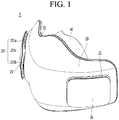
- FIG. 1 is a left perspective view of a mask apparatus
- FIG. 2 is a right perspective view of the mask apparatus
- FIG. 3 is a rear view of the mask apparatus
- FIG. 4 is a bottom view of the mask apparatus.
- a mask apparatus 1 includes a mask body 10 and a mask body cover 20 coupled to the mask body 10.
- the mask body 10 and the mask body cover 20 can be detachably coupled to each other.
- an inner space is defined between the mask body 10 and the mask body cover 20.
- Constituents for driving the mask apparatus 1 can be disposed in the inner space.
- the inner space is defined between a front surface of the mask body 10 and a rear surface of the mask body cover 20.
- the mask body 10 can define a rear surface of the mask apparatus 1, and the mask body cover 20 can define a front surface of the mask apparatus 1.
- a rear side of the mask apparatus 1 is defined as a direction in which the rear surface of the mask apparatus 1 facing a user's face is disposed, and a front side of the mask apparatus 1 is defined as a direction which is opposite to the rear side and in which a front surface of the mask apparatus 1, which is exposed to the outside, is disposed.
- the mask apparatus 1 can further include a sealing bracket 30 and a seal 40 that is detachably coupled to the sealing bracket 30.
- the sealing bracket 30 can be detachably coupled to a rear surface of the mask body 10 to fix the seal 40 to the rear surface of the mask body 10. In some examples, when the sealing bracket 30 is separated from the rear surface of the mask body 10, the seal 40 can be separated from the mask body 10.
- the seal 40 can be supported on the rear surface of the mask body 10 by the sealing bracket 30, and a breathing space S for breathing is defined between the seal 40 and the rear surface of the mask body 10.
- the seal 40 is in close contact with a user's face and surrounds user's nose and mouth to restrict introduction of external air into the breathing space S.
- the mask body cover 20 can include a first filter mounting portion 21 and a second filter mounting portion 22.
- the first filter mounting portion 21 can be disposed at a right side of the mask body cover 20, and the second filter mounting portion 22 can be disposed at a left side of the mask body cover 20.
- a left direction (left side) and a right direction (right side) are defined based on the mask apparatus 1 worn on the user's face. That is, in the state in which the user wearing the mask apparatus 1, a right side of the user is defined as the right side of the mask apparatus 1, and a left side of the user is defined as the left side of the mask apparatus 1.
- an upward direction (upward side) and a downward direction (downward side) are defined based on the mask apparatus 1 mounted on the user's face.
- a first filter cover 25 can be mounted on the first filter mounting portion 21, and a second filter cover 26 can be mounted on the second filter mounting portion 22.
- Filters 23 and 24 can be disposed inside the first filter mounting portion 21 and the second filter mounting portion 22, and the first filter cover 25 and the second filter cover 26 can cover the filter.
- the first filter cover 25 and the second filter cover 26 can be detachably coupled to the first filter mounting portion 21 and the second filter mounting portion 22, respectively.
- the first filter cover 25 and the second filter cover 26 can be coupled to be fitted into the first filter mounting portion 21 and the second filter mounting portion 22, respectively.
- Each of the first filter cover 25 and the second filter cover 26 can include a front surface portion and side surface portions extending backward along an edge of the front surface portion or an edge of a rear surface.
- Each of the side surface portions of the first filter cover 25 and the second filter cover 26 can have four side surfaces, and the four side surfaces can include an upper side surface, a lower side surface, a left side surface, and a right side surface.
- One or a plurality of first air inlets 251 can be defined in the side surface portion of the first filter cover 25.
- One or a plurality of second air inlets 261 can also be defined in the side surface portion of the second filter cover 26.
- the first air inlet 251 can be defined to be exposed to the outside.
- the second air inlet 261 can be defined to be exposed to the outside.
- the first air inlet 251 and the second air inlet 261 can be defined in the side surfaces of the first filter cover 25 and the second filter cover 26, respectively. In some examples, each of the first and second air inlets 251 and 261 can be respectively defined in the front surface portions of the first and second filter covers 25 and 26.
- the first air inlet 251 and the second air inlet 261 can be defined at a point closer to the front surface portion from a line that bisects the side surface portion.
- the first air inlets 251 can include a first air suction hole 251a defined in the right side surface, a second air suction hole 251b defined in the left side surface, and a third air suction hole 251c defined in the upper side surface.
- the second air inlets 261 can include a first air suction hole 261a defined in the left side surface, a second air suction hole 261b defined in the right side surface, and a third air suction hole 261c defined in the upper side surface.
- An opening 250 can be defined in one of the first filter cover 25 and the second filter cover 26, and the opening 250 can be defined in an edge of one of the first filter cover 25 and the second filter cover 26.
- a manipulation portion 195 for controlling an operation of the mask apparatus 1 can be mounted in the opening 250.
- the manipulation portion 195 can be mounted on the first filter cover 25.
- the manipulation portion 195 can serve as a manipulation switch that turns on/off power of the mask apparatus 1.
- the manipulation portion 195 can be exposed to the front side of the mask apparatus 1 while being mounted in the opening 250.
- the hook mounting portion 108 can include a first hook mounting portion 108a provided at a right side of the mask body 10, and a second hook mounting portion 108b provided at a left side of the mask body 10.
- Each of the first hook mounting portion 108a and the second hook mounting portion 108b can be provided in plurality to be spaced apart from each other in a vertical direction of the mask body 10.
- the first hook mounting portion 108a can be provided at each of the upper right and lower right sides of the mask body 10
- the second hook mounting portion 108b can be provided at each of the upper left and lower left sides of the mask body 10.
- a band for maintaining the mask apparatus 1 in close contact with the user's face can be mounted on the hook mounting portion 108.
- both ends of the band can connect the first hook mounting portion 108a to the second hook mounting portion 108b or connect each of two first hook mounting portions 108a spaced apart from each other in the vertical direction to each of two second hook mounting portions 108b spaced apart from each other in the vertical direction to each other.
- the band can have a shape surrounding the user's occipital region, and in the latter case, the band can have a shape that is hooked on both ears of the user.
- the hook mounting portion 108 can be formed by cutting a portion of the mask body 10. Thus, air can be introduced into the inner space between the mask body 10 and the mask body cover 20 through a gap defined in the hook mounting portion 108.
- the external air introduced into the inner space through the hook mounting portion 108 can cool electronic components disposed in the inner space.
- the air of which a temperature increases while cooling the electronic components can be discharged again to the outside of the mask body 10 through the hook mounting portion 108.
- the inside of the mask apparatus 1 can have a sealing structure.
- the electronic component can be or include an electronic device, an electric circuit, a battery, a controller, a fan, a memory, etc.
- the mask body 10 can include an air outlet 129 for supplying the filtered air to the breathing space S.
- the user can breathe while breathing the filtered air supplied through the air outlet 129 to the breathing space S.
- the air outlet 129 can include a first air outlet 129a through which the filtered air introduced into the first air inlet 251 is discharged to the breathing space S and a second air outlet 129b through which the filtered air introduced into the second air inlet 261 is discharged to the breathing space S.
- the first air outlet 129a can be defined at a right side with respect to a center of the mask body 10, and the second air outlet 129b can be defined at a left side with respect to the center of the mask body 10.
- the air introduced through the first air inlet 251 can pass through the filter 23 and then flow to the first air outlet 129a.
- the air introduced through the second air inlet 261 can pass through the second filter 24 and then flow to the second air inlet 261.
- the mask body 10 can include air exhaust holes 154 and 155 for discharging air exhaled by the user to an external space.
- the air exhaust holes 154 and 155 can be defined in a lower portion the mask body 10.
- the air exhaust holes 154 and 155 can include a first air exhaust hole 154 defined in a front lower end of the mask body 10 and a second air exhaust hole 155 defined in a bottom surface of the mask body 10.
- a rib extending forward can be formed at the front lower end of the mask body 10, and a surface defined by the rib can be defined as the bottom surface of the mask body 10.
- a flow space through the air flowing toward the second air exhaust hole 155 by passing through the first air exhaust hole 154 descends can be defined between the mask body 10 and the mask body cover 20.
- a check valve can be provided in one or more of the first air exhaust hole 154 and the second air exhaust hole 155.
- the external air can be introduced into the breathing space S, or the check valve can block backflow of the air discharged through the second air exhaust hole 155.
- the check valve can be disposed in the flow space between the first air exhaust hole 154 to the second air exhaust hole 155.
- the check valve having the form of a flat flap with a size and shape corresponding to the size and shape of the first air exhaust hole 154 can be provided.
- an upper end of the flap can be connected to an upper edge of the first air exhaust hole 154, and when the user exhales, the flap can be bent or rotates to open the first air exhaust hole 154, and when the user inhales, the flap can be in close contact with the first air exhaust hole 154 to help to prevent the external air or the discharged air from being introduced again into the breathing space.
- the mask body 10 can include a sensor mounting portion 109.
- the sensor mounting portion 109 can be equipped with a sensor for acquiring various pieces of information from the breathing space.
- the sensor mounting portion 109 can be disposed above the mask body 10. When the user breathes, the sensor mounting portion 109 can be disposed above the mask body 10 in consideration of a position at which a pressure change in the breathing space is constantly sensed.
- the mask body 10 can include a connector hole 135.
- the connector hole 135 can be understood as an opening in which a connector for supplying power to the mask apparatus 1 is installed.
- the connector hole 135 can be defined at either a left edge or a right edge of the mask body 10.
- the connector hole 135 can be provided at one side of the left or the right side of the mask body 10, which corresponds to the position at which the power module 19 is installed.
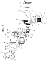
- FIG. 5 is an exploded perspective view of the mask apparatus.
- the mask apparatus 1 can include the mask body 10, the mask body cover 20, the sealing bracket 30, and the seal 40.
- the mask body 10 and the mask body cover 20 can be coupled to each other to form an outer appearance of the mask apparatus 1.
- An inner space for accommodating devices for the operation of the mask apparatus 1 can be defined between the mask body 10 and the mask body cover 20.
- the sealing bracket 30 and the seal 40 are coupled to the rear surface of the mask body 10 to define the breathing space between the user's face and the mask body 10.
- the sealing bracket 30 and the seal 40 can help to prevent the external air from being introduced into the breathing space.
- the mask body 10 can include a cover coupling groove 101.
- the cover coupling groove 101 can be defined along a front edge of the mask body 10.
- the cover coupling groove 101 can be defined by a height difference.
- the cover coupling groove 101 can be defined to correspond to an edge of the mask body cover 20.
- the cover coupling groove 101 can be defined by recessing a portion of the front surface of the mask body 10 backward.
- the mask body cover 20 can move toward the cover coupling groove 101 of the mask body 10 to allow the mask body cover 20 to be inserted into the cover coupling groove 101.
- the mask body 10 can include a first cover coupling portion 102.
- An upper portion of the mask body cover 20 can be supported on the first cover coupling portion 102.
- the first cover coupling portion 102 can be disposed on a front upper portion of the mask body 10.
- the first cover coupling portion 102 can have a structure that is capable of being hook-coupled.
- the hook coupled to the first cover coupling portion 102 can be disposed on a rear surface of the mask body cover 20.
- the first cover coupling portion 102 can be provided in plurality, and the hook can also be provided in plurality to correspond to the first cover coupling portions 102.
- the first cover coupling portion 102 can be provided at the left and right sides of the mask body 10 based on the center of the mask body 10, respectively.
- the first cover coupling portion 102 can be referred to as an upper cover coupling portion.
- the mask body 10 can include a first bracket coupling portion 103.
- the first bracket coupling portion 103 can be disposed above the mask body 10.
- the first bracket coupling portion 103 can support an upper portion of the sealing bracket 30.
- the first bracket coupling portion 103 can be disposed above a rear surface of the mask body 10.
- the first bracket coupling portion 103 can be provided by allowing a portion constituting the mask body 10 to protruding forward from the rear surface of the mask body 10.
- the first bracket coupling portion 103 can be understood as a recess when viewed from a rear side of the mask body 10 and a protrusion when viewed from a front side of the mask body 10.
- the sealing bracket 30 can include a first body coupling portion 304 that has the same shape as the recessed shape of the first bracket coupling portion 103 and is seated on the first bracket coupling portion 103.
- the first bracket coupling portion 103 can be provided at each of the left and right sides of the mask body 10.
- the first bracket coupling portion 103 can be defined as an upper bracket coupling portion.
- the mask body 10 can include a support rib 104.
- the support rib 104 can be provided to protrude forward from the front surface of the mask body 10.
- the support rib 104 can contact the rear surface of the mask body cover 20 when the mask body cover 20 is coupled to the mask body 10.
- the mask body 10 and the mask body cover 20 can resist external forces acting in a front and rear direction by the support rib 104.
- the support ribs 104 can be provided in a plurality on the front surface of the mask body 10.
- the support rib 104 can perform a function of fixing a portion of the control module 18 mounted on the mask body 10.
- the support rib 104 can include a hook shape.
- a hook protrusion can protrude from an end of the support rib 104 to fix the end of the control module 18.
- the mask body 10 can include a second cover coupling portion 106.
- a lower portion of the mask body cover 20 can be supported on the second cover coupling portion 106.
- the second cover coupling portion 106 can protrude in a hook shape from a front lower end of the mask body 10.
- the first cover coupling portion 102 can be provided at each of the left and right sides of the mask body 10 based on the center of the mask body 10.
- the second cover coupling portion 106 can be defined as a lower cover coupling portion.
- a hook hooking portion to which the second cover coupling portion 106 is coupled can be disposed on the mask body cover 20, and the hook hooking portion can be disposed at each of left and right sides of the mask body cover 20.
- the mask body 10 can include the second bracket coupling portion 107.
- a lower portion of the sealing bracket 30 can be supported on the second bracket coupling portion 107.
- the second bracket coupling portion 107 can be provided by opening the mask body 10.
- the second bracket coupling portion 107 can be disposed in a lower portion of the mask body 10.
- the second bracket coupling portion 107 can be provided as a through-hole defined in the mask body 10.
- a second body coupling portion 305 coupled to the second bracket coupling portion 107 can be disposed on the sealing bracket 30.
- the second bracket coupling portion 107 can be provided in plurality, and the second body coupling portion 305 can also be provided in plurality to correspond to the second bracket coupling portions 107.
- the second bracket coupling portion 107 can be provided at each of the left and right sides with respect to the center of the mask body 10.
- the second bracket coupling portion 107 can be defined as a lower bracket coupling portion.
- the mask body 10 can include the above-described sensor mounting portion 109.
- the sensor mounting portion 109 can have a rib shape in which a portion of the front surface of the mask body 10 protrudes forward.
- the sensor mounting portion 109 has a rib shape that is surrounded along an edge of the sensor, and an installation space in which the sensor is installed is defined in the sensor mounting portion 109.
- a hole through which the installation space and the breathing space communicate with each other is defined in the mask body 10 corresponding to the inside of the sensor mounting portion 109.
- the sensor disposed in the installation space can include a pressure sensor, and the pressure sensor can sense pressure information of the breathing space through the hole.
- the mask body 10 can include a fan module mounting portion 110.
- the fan module mounting portion 110 can include a first fan module mounting portion on which a first fan module 16 is mounted and a second fan module mounting portion on which a second fan module 17 is mounted.
- the first fan module mounting portion and the second fan module mounting portion can be disposed on the front surface of the mask body 10.
- the first fan module mounting portion can be disposed at the right side of the mask body 10
- the second fan module mounting portion can be disposed at the left side of the mask body 10.
- the first fan module 16 and the second fan module 17 can be detachably coupled to the first fan module mounting portion and the second fan module mounting portion, respectively.
- the mask body 10 can include an air duct 120.
- the air duct 120 can be disposed on the front surface of the mask body 10. A passage through which air passes can be provided in the air duct 120.
- the air duct 120 can include a first air duct connected to the first fan module mounting portion and a second air duct connected to the second fan module mounting portion.
- the first air duct and the second air duct can be disposed on an edge of the first fan module mounting portion and an edge of the second fan module mounting portion, which are adjacent to the center of the front surface of the mask body 10 so as to be disposed between the first fan module mounting portion and the second fan module mounting portion.
- first fan module mounting portion and the second fan module mounting portion can have a shape symmetrical with respect to a vertical plane (or a vertical line) passing through the center of the front surface of the mask body 10.
- first air duct and the second air duct can also have a shape symmetrical with respect to the vertical plane or the vertical line passing through the center of the front surface of the mask body 10.
- One end of the air duct 120 communicates with the outlets of the fan modules 16 and 17 to allow the external air to be introduced into the air duct 120.
- the other end of the air duct 120 communicates with the air outlet 129 so that the air introduced into the air duct 120 is discharged into the breathing space S.
- a control module 18 can be mounted on the front surface of the air duct 120.
- a control module mounting portion 128 for mounting the control module 18 can be disposed on the front surface of the air duct 120.
- a portion of the front surface of the air duct 120 can be provided as a flat portion on which the control module 18 is capable of being seated, and the flat portion can be defined as the control module mounting portion 128.
- the control module mounting portion 128 can include a first control module mounting portion 128a provided in the first air duct and a second control module mounting portion 128b provided in the second air duct.
- One control module 18 can be fixed to the first control module mounting portion 128a and the second control module mounting portion 128b, or a plurality of control modules can be respectively fixed to the first and second control module mounting portions 128a and 128b.
- the mask body 10 can include a power module mounting portion 130 for mounting the power module 19.
- the power module mounting portion 130 can be disposed on the front surface of the mask body 10.
- the power module mounting portion 130 can be provided at one of the left and the right side of the mask body 10.
- the power module mounting portion 130 can be disposed at the side of the fan module mounting portion 110. Specifically, the power module mounting portion 130 can be provided between the fan module mounting portion 110 and a side end of the mask body 10. The side end of the mask body 10 can be defined as an end adjacent to the user's ear when worn. In some examples, a connector hole 135 can be defined in the side end of the mask body 10 provided with the power module mounting portion 130.
- the mask body 10 can include a battery mounting portion 140 for mounting a battery.
- the battery mounting portion 140 can be disposed on the front surface of the mask body 10.
- the battery mounting portion 140 can be provided to protrude forward from the front surface of the mask body 10 so as to surround the battery.
- the battery mounting portion 140 can include a pair of guide ribs protruding forward from the front surface of the mask body 10 and a connection rib connecting front ends of the pair of guide ribs to each other.
- the battery can be mounted in a battery accommodation space defined by the pair of guide ribs and the connection rib.
- the battery can move downward from an upper side of the battery accommodating space and be inserted into the battery accommodating space and then can move in a reverse direction to be separated.
- a lower portion of the battery inserted into the battery mounting portion 140 can be supported by an air discharge portion 150 that defines an air outlet.
- the mask body 10 can include the air discharge portion 150.
- the air discharge portion 150 can be disposed in a lower portion of the mask body 10.
- the air discharge portion 150 can define a flow space through which the air flowing from the first air exhaust hole 154 toward the second air exhaust hole 155 passes.
- the air discharge portion 150 can protrude forward from the front surface of the mask body 10.
- the air discharge portion 150 can extend to be rounded in an arch shape or can be bent several times to extend.
- a front end of the air discharge portion 150 can be in contact with the rear surface of the mask body cover 20, and the inner space of the mask body 10 and the flow space can be distinguished from each other.
- the air discharge portion 150 can define a top surface and both side surfaces of the flow space, and a rear surface of the mask body cover 20 can define a front surface of the flow space.
- the front surface of the mask body 10 can define a rear surface of the flow space, and the bottom surface of the mask body 10 on which the second air exhaust hole 155 is defined can define a bottom surface of the flow space.
- the top surface of the air discharge portion 150 can support a lower end of the battery. It is connected to lower ends of both sides of the air discharge portion 150 having the arch shape or tunnel shape can be connected to the bottom surface of the mask body 10, and the bottom surface of the mask body 10 can be defined by the rib extending forward from the lower end of the front surface of the mask body 10.
- the cover coupling groove 101 is recessed along the front end of the rib defining the bottom surface of the mask body 10, and the lower end of the rear surface of the mask body cover 20 is coupled to the cover coupling groove 101.
- the first air exhaust hole 154 can be defined in the front surface of the mask body 10 defining the rear surface of the flow space.
- the mask body cover 20 can include a pair of filter mounting portions 21 and 22, as described above.
- the filter mounting portions 21 and 22 can be provided by recessing the front surface of the mask body cover 20 to be recessed by a predetermined depth toward the rear surface of the mask body cover 20. Filters 23 and 24 are accommodated inside the filter mounting portions 21 and 22 provided by being recessed, and filter covers 25 and 26 can be mounted on edges of the filter mounting portions 21 and 22 in the state in which the filters 23 and 24 are accommodated.
- Air suction ports 211 and 221 can be defined in the filter mounting portions 21 and 22.
- the air suction ports 211 and 221 can communicate with suction holes defined in the front surfaces of the fan modules 16 and 17, respectively.
- Each of edges of the air suction ports 211 and 221 can have an inclined surface that inclined in a direction in which a diameter gradually decreases from the front surface to the rear surface.
- a filter cover mounting groove 212 for fixing each of the filter covers 25 and 26 can be defined in a side surface of each of the filter mounting portions 21 and 22.
- a coupling protrusion inserted into the filter cover mounting groove 212 and 222 can be disposed on each of the filter covers 25 and 26.
- FIG. 5 only the coupling protrusion 262 disposed on the left filter cover 26 is illustrated, but it is noted that the same coupling protrusion is disposed on the right filter cover 25 as well.
- a sealing material for sealing can be provided between the edges of the rear surfaces of the air suction ports 211 and 221 of the filter mounting portions 21 and 22 and the fan inlets of the fan modules 16 and 17.
- the sealing material can surround the air suction ports 211 and 221 and edges of the fan inlets of the fan modules 16 and 17 to block introduction of the external air.
- the filter mounting portions 21 and 22 include a first filter mounting portion 21 provided at the right side of the mask body cover 20 and a second filter mounting portion 22 provided at the left side of the mask body cover 20.
- the air suction hole defined in the first filter mounting portion 21 can be defined as a first air suction port 211, and the air suction hole defined in the second filter mounting portion 22 can be defined as a second air suction port 221.
- the filters 23 and 24 can include a first filter 23 accommodated inside the first filter mounting portion 21 and a second filter 24 accommodated inside the second filter mounting portion 22.
- the filter covers 25 and 26 can include a first filter cover 25 mounted on the first filter mounting portion 21 and a second filter cover 26 mounted on the second filter mounting portion 22.
- a plurality of first air inlets 251 can be defined in the first filter cover 25 to allow the external air to be introduced, and a plurality of second air inlets 261 can be defined in the second filter cover 26 to allow the external air to be introduced.
- the control module 18 can be referred to as a first electronic circuit device, and the power module 19 can be referred to as a second electronic circuit device.
- the fan modules 16 and 17 can include a fan, a fan motor, and a fan housing accommodating the fan and the fan motor.
- the fan housing can include a suction hole through which the air is introduced into the fan, and a discharge hole through which the air forcedly flowing by the fan is discharged.
- the fan may be any on of various types of fans.
- the fan may be a centrifugal fan that suctions air from the front side of the mask body cover 20 and discharges the air to the side of the mask body 10.
- the fan may be an axial fan or a cross flow fan.
- the air introduced through the first air inlet 251 to pass through the first filter 23 is suctioned through the first air suction port 211.
- the air introduced through the second air inlet 261 to pass through the second filter 24 is suctioned through the second air suction port 221.
- the fan outlet of the first fan module 16 can communicate with the first air duct to discharge the air to the breathing space
- the fan outlet of the second fan module 17 can communicate with the second air duct to discharge the air to the breathing space.
- the control module 18 can control an operation of the mask apparatus 1.
- the control module 18 can be fixed to the control module mounting portion 128.
- the control module 18 can include a communication module to transmit and receive various types of information.
- the control module 18 can include a data storage module to store various types of information.
- the control module 18 can control an operation of each of the fan modules 16 and 17.
- the control module 18 can control the operation of each of the fan modules 16 and 17 based on information sensed from the sensor.
- the control module 18 can be electrically connected to the power module 19, the fan modules 16 and 17, and the battery so as to be interlocked with each other.
- the power module 19 can receive power from the outside.
- the power module 19 can include a charging circuit for charging the battery.
- the power module 19 can include the connector 192 and the manipulation portion 195.
- the control module 18 can operate by receiving battery power or external power through the connector 192.
- the power module 19 can control supply of power to the mask apparatus 1 by the manipulation portion 195.
- the power module 19 can control supply of power from the battery to the control module 18 and the fan modules 16 and 17.
- the seal 40 can be coupled to the rear surface of the mask body 10 by the sealing bracket 30 to be in close contact with the user's face.
- the rear surface of the mask body 10 can be spaced apart from the user's face by the seal 40.
- the sealing bracket 30 can be provided in a ring shape forming a closed loop.
- the seal 40 can be detachably coupled to the sealing bracket 30.
- the sealing bracket 30 is coupled to be detachable from the mask body 10 to separate the sealing bracket 30 from the mask body 10. With this structure, only the sealing bracket 30 is separated, or an assembly of the seal 40 and the sealing bracket 30 is separated from the mask body 10 to clean only sealing bracket 30 or clean both the sealing bracket 30 and the seal 40.
- the seal 40 is coupled to the sealing bracket 30, when the sealing bracket 30 is coupled to the mask body 10, the seal 40 is stably fixed to the mask body 10.
- the sealing bracket 30 can include a sealing insertion portion 301 inserted into an inner edge of the seal 40.
- the inner edge of the seal 40 can be provided in a shape of seal lips that is branched into two portions, and the sealing insertion portion 301 can be inserted into the seal lips (see FIG. 13 ) .
- the sealing insertion portion 301 can have a cross-sectional shape having a constant thickness or a cross-sectional shape of which a thickness decreases from an inner edge toward an outer edge.
- a body of the sealing bracket 30 can be provided by the sealing insertion portion 301 and a fixing guide 302 to be described later.
- the sealing bracket 30 can include the fixing guide 302.
- the fixing guide 302 can be bent at an inner end of the sealing insertion portion 301.
- the sealing insertion portion 301 is completely inserted into the seal lips of the seal 40, one of the two seal lips is in contact with the fixing guide 302. That is, when the inner edge of the seal 40 is in contact with the fixing guide 302, it is seen that the seal 40 is completely coupled to the sealing bracket 30.
- the sealing bracket 30 can include a bracket insertion portion 306 coupled to the mask body 10.
- the bracket insertion portion 306 is inserted into a cutoff portion defined in the rear surface of the mask body 10 to cover a portion of an edge of the cutoff portion.
- the cutoff portion can be understood as an opening communicating with the air duct 120 so that the air passes therethrough.
- the bracket insertion portion 306 can be disposed on one edge of the cutoff portion, specifically, an outer edge.
- the air outlet 129 already described can be understood as the remaining portion of the cutoff portion that is not covered by the bracket insertion portion 306 in a state in which the bracket insertion portion 306 is inserted into one side of the cutoff portion.
- the air discharged from the fan modules 16 and 17 can pass between the air duct 120 and the bracket insertion portion 306 to flow to the air outlet 129.
- the bracket insertion portion 306 can serve as a function of fixing the sealing bracket 30 to the mask body 10 while defining one surface of the air duct 120.
- an upper portion of the sealing bracket 30 can be fixed to the upper portion of the mask body 10 by the first body coupling portion 304
- a lower portion of the sealing bracket 30 can be fixed to the lower portion of the mask body 10 by the second body coupling portion 305
- an intermediate portion of the sealing bracket 30 can be fixed to an intermediate portion of the mask body 10 by the bracket insertion portion 306.
- the seal 40 can be made of a material having elasticity.
- the seal 40 can be in close contact with the user's face and deformed to correspond to an outline of the user's face.
- the seal 40 can be provided in a ring shape forming a closed loop.
- the seal 40 can be provided to cover the user's nose and mouth.
- the seal 40 includes a coupling portion 400a coupled to the mask body 10, a side surface portion 400c extending from the coupling portion 400a toward the user's face, and a contact portion 400b that is bent from an end of the side surface portion 400c to extend toward the coupling portion 400a.
- the contact portion 400b can be a portion that is in close contact with the user's face, and the side surface portion 400c and the contact portion 400b can be angled at an angle of about 90 degrees or less to define a space between the side surface portion 400c and the contact portion 400b.
- a first opening can be defined inside the coupling portion 400a of the seal 40, and a second opening can be defined inside the contact portion 400b.
- the second opening can include a main opening in which the front of the user's nose and mouth are disposed and a sub opening extending from an upper end of the main opening and disposed on the user's nose.
- a lower portion of the main opening that is, a portion that is in close contact with the front of the user's jaw can be designed closer to the mask body 10 than a portion that is in close contact with the front of the user's cheek.
- a plurality of ventilation holes can be defined in the contact portion 400b to minimize a phenomenon in which moisture is generated on the user's cheek.
- the plurality of ventilation holes can have different sizes. For example, a diameter of the ventilation hole can gradually increase from an inner edge to an outer edge of the contact portion 400b.
- the air outlet 129 and the air exhaust holes 154 and 155 can be provided inside the first opening, and the user's nose and mouth can be disposed inside the second opening.
- the seal 40 is disposed between the user's face and the mask body 10, and the breathing space S is defined by the coupling portion 400a, the contact portion 400b, and the inner side of the side surface portion 400c of the seal 40.
- a bracket insertion groove 401 can be defined in an end of the coupling portion 400a of the seal 40.
- the bracket insertion groove 401 can be understood as a groove or a space defined between the two seal lips when the coupling portion 400a has the shape that is branched into the two seal lips as described above, and the bracket insertion portion 305 of the sealing bracket 30 is inserted into the bracket insertion groove 401.
- the seal 40 includes a first seating portion 404 on which the first body coupling portion 304 is seated, a second seating portion 405 on which the second body coupling portion 305 is seated, and a third seating portion 406 on which the bracket insertion portion 306 is seated.
- the first and third seating portions 404 and 406 can be understood as grooves in which a portion of the seal 40 is cut to form an accommodation space in which the first body coupling portion 304 and the bracket insertion portion 306 are accommodated.
- the second seating portion 405 can be understood as a hole in which a portion of the seal 40 is cut to pass through the second body coupling portion 305.
- first mounting portion 404 can be defined as a first opening
- second mounting portion 405 can be defined as a second opening
- third mounting portion 406 can be defined as a third opening.
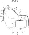
- FIGS. 6 and 7 are views illustrating a flow of air when the mask apparatus operates.
- the mask apparatus 1 can suction the external air through the air inlets 251 and 261 provided in the filter covers 25 and 26.
- the flow direction of the external air suctioned into the mask apparatus 1 is indicated by an arrow "A" Since the air inlets 251 and 261 are provided in plurality to suction the air in various directions, an inflow rate of the external air increases.
- the air inlets 251 and 261 can include air inlets 251a and 261a for suctioning air flowing at upper sides of the filter covers 25 and 26, air inlets 251b and 261b for suctioning air flowing at a front side of the filter covers 25 and 26, and air inlets 251c and 261c for suctioning air flowing at a lower side of the filter covers 25 and 26.
- the side air inlets 251b and 261b can be provided at one or both sides of the left and right sides of the filter covers 25 and 26.
- the filter covers 25 and 26 in which the air inlets 251 and 261 are provided are respectively disposed at left and right sides of the front surface of the mask apparatus 1, the external air can be smoothly suctioned from the left and right sides of the front surface of the mask apparatus 1.
- the external air introduced through the air inlets 251 and 261 can be filtered by passing through the filters 23 and 24 disposed inside the filter mounting portions 21 and 22.
- the filters 23 and 24 can be replaced when the filter covers 25 and 26 are separated from the mask apparatus 1.
- the air passing through the filters 23 and 24 can be introduced into the suction holes of the fan modules 16 and 17 through the air suction ports 211 and 221.
- the air can pass through the filter without leakage, and the external air may not enter between the filter mounting portions 21 and 22 and the fan modules 16 and 17.
- the air discharged through the fan outlets of the fan modules 16 and 17 can pass through the air duct 120 to flow into the breathing space S through the air outlet 129.
- a flow direction of the air introduced into the breathing space S through the air outlet 129 is indicated by an arrow "B"
- the breathing space S can be defined by the mask body 10 and the seal 40.
- the seal 40 can be in close contact with the mask body 10 and the user's face to form an independent breathing space that is separated from the external space.
- the user inhales after suctioning the filtered air supplied through the air outlet 129 can be exhausted to the external space through the air exhaust holes 154 and 155.
- the air exhaust holes 154 and 155 include a first air exhaust hole 154 communicating with the breathing space and a second air exhaust hole 155 communicating with the external space, and the first air exhaust hole 154 and the second air exhaust hole 155 can communicate with each other by the flow space defined by the air discharge portion 150.
- the air exhaled by the user can be guided into the flow space through the first air exhaust hole 154.
- a flow direction of the air flowing into the flow space through the first air exhaust hole 154 is indicated by an arrow "C"
- the air guided into the flow space through the first air exhaust hole 154 can be discharged to the external space through the second air exhaust hole 155.
- a flow direction of the air flowing to the external space through the second air exhaust hole 155 is indicated by an arrow "D".
- FIG. 8 is a front perspective view of the mask body cover
- FIG. 9 is a rear perspective view of the mask body cover.
- the mask body cover 20 can be coupled to the front of the mask body 10.
- the mask body cover 20 can be provided to be elongated in the left and right direction, and a center portion of the mask body cover 20 can be convexly rounded forward.
- the mask body cover 20 can be provided to be symmetrical to each other in the left and right direction with respect to a vertical surface passing through a center of the front surface thereof.
- the mask body cover 20 can include a cover front surface 201 defining an outer surface or a front surface thereof, and a cover rear surface 202 defining an inner surface or a rear surface thereof.
- the cover front surface 201 can be a portion that is exposed to the outside to define an outer appearance thereof when the user wears the mask apparatus 1.
- the cover front surface 201 can include a first filter mounting portion 21 on which the first filter 23 is mounted and a second filter mounting portion 22 on which the second filter 24 is mounted.
- the first filter mounting portion 21 and the second filter mounting portion 22 can be provided to be symmetrical to each other in the left and right direction with respect to the center of the front surface 201 of the cover.
- the first filter mounting portion 21 and the second filter mounting portion 22 can have the same or similar shape to each other.
- the first filter mounting portion 21 and the second filter mounting portion 22 can be provided by partially recessing the front surface 201 of the cover.
- a portion of the front surface 201 of the cover can be recessed backward to define a space in which the first filter 23 and the second filter 24 are seated.
- each of the first filter mounting portion 21 and the second filter mounting portion 22 can have a bottom surface, on which the first filter 23 and the second filter 24 contact and are supported, and a plurality of side surfaces defining edges of the bottom surface.
- a first air suction port 211 through which external air is suctioned can be defined in the bottom surface of the first filter mounting portion 21.
- the air passing through the first filter 23 can be suctioned into the first fan module 16 through the first air suction port 211.
- the first air suction port 211 can be disposed at a center of the bottom surface.
- the first air suction port 211 can be provided to be opened in a circular shape.
- At least one or more first filter cover mounting grooves 212 for mounting the first filter cover 25 can be defined in the side surfaces of the first filter mounting portion 21.
- the first filter cover mounting groove 212 can be defined by being further recessed inward from the side surface of the first filter mounting portion 21.
- the coupling protrusion 262 protruding from the edge of the first filter cover 25 can be fitted and coupled to the first filter cover mounting groove 212 and then be mounted on the first filter mounting portion 21.
- the first filter cover mounting groove 212 can be defined in each of two side surfaces of the first filter mounting portion 21 facing each other.
- the first filter cover mounting groove 212 can include one or a plurality of mounting grooves defined in one of the two side surfaces facing each other and one or a plurality of mounting grooves defined in the other of the two side surfaces.
- At least one of the side surfaces of the first filter mounting portion 21, i.e., one of the two side surfaces, in which the first filter cover mounting groove is defined, can be provided to be inclined.
- a side adjacent to a front center of the filter cover 25 can be provided to be gradually inclined in a direction that is close to the front center of the filter cover 25 toward the front surface of the filter cover 25.
- the reason in which at least one of the side surfaces of the first filter mounting portion 21 is provided to be inclined is to facilitate detachment of the first filter cover 25. That is, when the side in which the first filter cover mounting groove 212 is defined is provided to be inclined, in a state in which the coupling protrusion 262 protruding from one side end of the first filter cover 25 is inserted into the first filter cover mounting groove 212, the coupling protrusion 262 can be inserted into the first cover mounting portion 21 while the other side end of the first filter cover 25 is slid along the inclined side surface.
- the first cover mounting portion 21 can define a groove.
- a second air suction port 221 through which external air is suctioned can be defined in the bottom surface of the second filter mounting portion 22. The air passing through the second filter 24 can be suctioned into the second fan module 17 through the second air suction port 221.
- the second air suction port 221 can be disposed at a center of the bottom surface.
- the second air suction port 221 can be provided to be opened in a circular shape.
- At least one or more second filter cover mounting grooves 222 for mounting the second filter cover 26 can be defined in side surfaces of the second filter mounting portion 22.
- the second filter mounting portion 22 has a shape that is symmetrical to the shape of the first filter mounting portion 21, duplicated descriptions of the second filter mounting portion 22 will be omitted.
- the cover rear surface 202 is coupled to cover the entire surface of the mask body 10 and serves to protect a plurality of devices mounted on the mask body 10.
- a plurality of coupling ribs for coupling to the mask body 10 can be disposed on the rear surface 202 of the cover.
- the plurality of coupling ribs can be provided to protrude backward from the cover rear surface 202.
- the plurality of coupling ribs can include a first coupling rib 203 provided above the cover rear surface 202 and a second coupling rib 204 provided below the cover rear surface 202.
- the first coupling rib 203 can be disposed above the cover rear surface 202, and the second coupling rib 204 can be disposed below the cover rear surface 202.
- the first coupling rib 203 can be fitted and coupled to the first cover coupling portion 102 provided on the mask body 10.
- the first coupling ribs 203 can be provided in plurality so as to be spaced apart from an upper portion of the cover rear surface 202 to both sides.
- the second coupling rib 204 can be fitted and coupled to the second cover coupling portion 106 provided on the mask body 10.
- the second coupling ribs 204 can be plurality in plurality so as to be spaced apart from an upper portion of the cover rear surface 202 to both sides.
- an interval between the plurality of second coupling ribs 204 can be greater than that between the plurality of first coupling ribs 203.
- the plurality of coupling ribs can further include a third coupling rib 205 provided under the cover rear surface 202.
- the third coupling rib 205 can be fitted and coupled to the air outlet 150 provided in the mask body 10.
- the third coupling rib 205 can be provided between the plurality of second coupling ribs 204.
- the third coupling rib 205 includes a horizontal rib 205a protruding horizontally backward from the cover rear surface 202 and a vertical rib 205b extending downward from both sides of the horizontal rib 205a.
- the air outlet 150 can be coupled to surround outer edges of the horizontal rib 205a and the vertical rib 205b.
- at least a portion of the third coupling rib 205 can be coupled in close contact with the inner side of the air outlet 150.
- FIG. 10 is a front perspective view of the mask apparatus, from which the mask body cover and a battery are removed
- FIG. 11 is a left perspective view of the mask apparatus, from which the mask body cover is removed
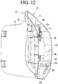
- FIG. 12 is a longitudinal cross-sectional view of the mask apparatus
- FIG. 13 is a left perspective view of a mask body
- FIG. 14 is a front view of the mask body.
- the mask apparatus 1 includes a mask body 10 on which a plurality of electronic components is installed, and a mask body cover 20 detachably coupled to the mask body 10.
- the mask body cover 20 can cover the plurality of electronic components mounted on the mask body 10 to prevent the plurality of electronic components from being exposed to the outside.
- the entire surface of the mask body 10 can be exposed as illustrated in FIG. 10 .
- the mask body 10 can be coupled to the rear of the mask body cover 20.
- the mask body 10 can be provided to be elongated in the left and right direction, and a center portion of the mask body 10 can be convexly rounded forward.
- the mask body 10 can be provided symmetrically in a horizontal direction with respect to the vertical surface passing through the center. That is, the mask body 10 can have a shape and size corresponding to the mask body cover 20.
- the mask body 10 can include a body front surface 11 coupled to the mask body cover 20 and a body rear surface 12 coupled to the sealing bracket 30 or the seal 40.
- the body front surface 11 defines a space in which the plurality of electronic components is mounted, and a plurality of structures coupled with the mask body cover 20 are provided.
- a battery 13 can be disposed at the center of the body front surface 11.
- the battery 13 can supply power to at least one of the control module 18, the power module 19, or the fan modules 16 and 17.
- the battery 13 can have sufficient capacity to enable high-speed rotation of the fan modules 16 and 17.
- the battery 13 can be provided in a plurality and connected to in parallel to each other.
- the battery 13 two batteries, each of which has a capacity of 400 mAh, can be connected to each other in parallel to each other.
- the battery 13 can be provided as a relatively light lithium ion battery.
- the battery 13 has an advantage that the battery capacity increases relative to the same weight to increase in driving time and enable a high-speed operation of the fan.
- the battery 13 can be provided with one large-capacity battery.
- the battery 13 can be relatively heavy among the electronic components. Thus, the battery 13 can be disposed at a central portion of the mask body 10 hung on the user's nose.
- the battery 13 can be relatively heavy among the electronic components. Thus, the battery 13 can be disposed at a central portion of the mask body 10 hung on the user's nose.
- the battery 13 can be disposed between the first fan module 16 and the second fan module 17.
- the battery 13 can be disposed at an intermediate point between the first fan module 16 and the second fan module 17.
- the first fan module 16, the battery 13, and the second fan module 17 can be arranged in a line in the widthwise direction of the body front surface 11. As a result, a load can be dispersed to left and right sides of the mask apparatus.
- the user can feel less load on his/her ears when wearing the mask apparatus 1, when compared to a case in which the battery 13 is disposed at the edge of the mask body 10.
- the battery 13 is disposed at the center of the mask body 10, power can be easily provided to some or all of the control module 18, the power module 19, and the fan modules 16 and 17. That is, wires can be connected to various electronic components to supply power.
- a battery mounting portion 140 supporting the battery 13 is disposed at the central portion of the body front surface 11.
- the battery mounting portion 140 can have a rib shape protruding forward from the body front surface 11.
- the battery mounting portion 140 can include a pair of vertical ribs 141, each of which is disposed to be elongated in the vertical direction on the body front surface 11, and a horizontal rib 142 connecting the pair of vertical ribs 141 to each other.
- the pair of vertical ribs 141 can be provided to be spaced apart from each other in the left and right direction so as to be symmetrical to each other with respect to the center of the body front surface 11.
- each front end of the pair of vertical ribs 141 can be bent in a direction facing each other to provide the horizontal ribs 142.
- the pair of vertical ribs 141 and horizontal ribs 142 can define an accommodation space 143 that accommodates the battery 13.
- a front surface of the battery 13 can be supported by the horizontal ribs 142, and a side surface of the battery 13 can be supported by the vertical ribs 141.
- a lower end of the battery 13 can be supported by an upper end of the air discharge portion 150.
- a top surface of the air discharge portion 15 can have a horizontal surface.
- the lower portion of the battery 13 can be supported in contact with the top surface of the air discharge portion 15. As a result, the battery 13 can be in a state in which all the front, side, and bottom surfaces of the battery 13 are supported by the vertical ribs 141, the horizontal ribs 142, and the air discharge portion 15.
- the battery 13 can be restricted from being removed from the battery mounting portion 140, and the battery 13 can be stably supported.
- the battery 13 since the battery 13 is disposed adjacent to the upper portion of the air discharge portion 15, the battery 13 can be naturally cooled by the air discharged through the air discharge portion 15. In detail, since the lower end of the battery 13 is in direct contact with the top surface of the air discharge portion 15, the battery 13 can be more quickly cooled through heat conduction. That is, air exhaled by the user can absorb heat released from the battery 13 and then can be discharged to the outside of the mask apparatus 1.
- a control module 18 is disposed at a center of the body front surface 11.
- the control module 18 can be electrically connected to the power module 19, the fan modules 16 and 17, and the battery 13.
- the control module 18 can be seated on the front surface of the air duct 120 through which air suctioned from the fan modules 16 and 17 flows and can be cooled by air flowing along the air duct 120. That is, heat generated in the control module 18 can be transferred to the air flowing along the air duct 120 through heat conduction between the front surface of the air duct 120 and the control module 18.
- the control module 18 can include a processor, a controller, an electric circuit, an integrated circuit, or the like.
- control module 18 can be disposed between the first fan module 16 and the second fan module 17.
- control module 18 can be disposed at the intermediate point between the first fan module 16 and the second fan module 17.
- the first fan module 16, the control module 18, and the second fan module 17 can be arranged on the body front surface 11 in a line in the widthwise direction of the body front surface 11. That is, the first fan module 16 and the second fan module 17 can be horizontally symmetrically disposed with respect to the control module 18.
- control module 18 can be disposed to surround the battery 13.
- the central portion of the control module 18 can be opened, and the battery 13 can be disposed at the opened center of the control module 18.
- the control module 18 can have an n-shape with an opened central portion to avoid an interference with the battery 13.
- the control module 18 can be provided as an n-shaped single substrate, or a plurality of substrates 18a, 18b, and 18c can be connected to each other to define the n-shape.
- the substrate constituting the control module 18 can include a first substrate 18a disposed at a right side and a second substrate 18b disposed on at left side with respect to the body front surface 11.
- the substrate constituting the control module 18 can further include a third substrate 18c connecting the first substrate 18a to the second substrate 18b.
- the first substrate 18a, the second substrate 18b, and the third substrate 18c can be integrated with each other.
- the first substrate 18a can be disposed at a right side of the battery 13, the second substrate 18b can be disposed at a left side of the battery 13, and the third substrate 18c can be disposed above the battery 13.
- the third substrate 18c can be disposed to avoid overlapping with the battery 13.
- the battery 13 and the control module 18 can be efficiently and densely disposed within a limited space.
- Control module mounting portions 128a and 128b on which the control module 18 is mounted are disposed on the body front surface 11.
- the control module mounting portions 128a and 128b can be provided so that a portion of the front surface of the air duct 120 is provided in a plane.
- Coupling portions 125a and 125b for coupling the substrates 18a, 18b, and 18c of the control module 18 are disposed on the control module mounting portions 128a and 128b.
- the plurality of coupling portions 125a and 125b can be disposed on the first control module mounting portion 128a and the second control module mounting portion 128b, respectively.
- the plurality of coupling portions 125a, 125b pass through portions of edges of the substrates 18a, 18b, 18c, respectively, so that the control module 18 is fixed to the control module mounting portions 128a, 128b.
- a separate coupling member can pass through the substrates 18a, 18b, and 18c to be coupled to the control module mounting portions 128a and 128b.
- the first substrate 18a can be disposed on the first control module mounting portion 128a of the air duct 120
- the second substrate 18b can be disposed on the second control module mounting portion 128b of the air duct 120
- the third substrate 18c can be disposed above the air duct 120.
- a plurality of heat generation elements are densely arranged in the central portion of the mask apparatus 1.
- heat generation elements e.g., the control module 18, the battery 13, etc.
- the mask apparatus 1 further includes a pressure sensor 14.
- the pressure sensor 14 can be disposed on a sensor mounting portion 109 disposed on the body front surface 11 to sense a pressure of a breathing space.
- the pressure sensor 14 can be installed on the substrate of the control module 18 and can be disposed in an installation space defined inside the sensor mounting portion 109.
- the pressure sensor 14 can be installed on the third substrate 18c to protrude to the rear of the third substrate 18c.
- the third substrate 18c can be disposed in front of the sensor mounting portion 109.
- the pressure sensor 14 When the pressure sensor 14 is disposed in the installation space of the sensor mounting portion 109, information of the breathing space can be obtained from air introduced into the installation space through a hole communicating with the installation space and the breathing space.
- Pressure information or breathing information sensed by the pressure sensor 14 can be provided to the control module 18, and operations of the fan modules 16 and 17 can be controlled based on the pressure information and breathing information.
- the sensor mounting portion 109 can have a rectangular shape of which the inside is empty, but is not limited thereto.
- the sensor mounting portion 109 can include a first portion 109a having a predetermined width and protruding in a direction parallel to the ground, a pair of second portions 109c extending downward from each of both sides of the first portion 109a, and a third portion 109b connecting ends of the pair of second portions 109c to each other.
- the first portion 109a can define a top surface of the sensor mounting portion 109
- the second portion 109c can define both side surfaces of the sensor mounting portion 109
- the third portion 109b can define a bottom surface of the sensor mounting portion 109.
- the first fan module 16 and the second fan module 17 are disposed on both sides of the body front surface 11, respectively.
- the first fan module 16 can be disposed at a right side of the control module 18, and the second fan module 17 can be disposed at a left side of the control module 18.
- the first fan module 16 is mounted on a first fan module mounting portion 110a disposed at the right side of the body front surface 11, and the second fan module 17 is mounted on a second fan module mounting portion 110b disposed at the left side of the body front surface 11.
- the first fan module 16 and the second fan module 17 can be disposed to be symmetrical to each other in the left and right direction with respect to the center of the mask body 10.
- the power module 19 can be disposed on the edge of the body front surface 11.
- the power module 19 can receive power from a power source to perform a function of turning on or off the power of the mask apparatus 1.
- the power module 19 can be disposed on a side of any one of the first fan module 16 and the second fan module 17. That is, the power module 19 can be disposed on a left edge or a right edge of the body front surface 11.
- a power module mounting portion 130 for mounting the power module 19 is disposed on the body front surface 11.
- the power module mounting portion 130 can include a plurality of ribs, which are disposed on the left edge or the right edge of the body front surface 11 to support the power module 19.
- the battery 13, the control module 18, the fan modules 16 and 17, and the power module 19 can be arranged in a line in a widthwise direction of the mask body 10.
- the widthwise direction of the mask body 10 can be parallel to a left-right direction extending through the fan modules 16 and 17.
- the mask apparatus 1 since the plurality of electronic components are densely disposed within the limited space of the mask apparatus 1, there can be an advantage that the mask apparatus 1 is compact. In some examples, since the electronic components such as the battery 13 and the control module 18, which increase in temperature due to the heat generation, are disposed at the point adjacent to the air passage through which air is inhaled by the user flows, the heat of the battery 13 and the control module 18 can be naturally cooled.
Landscapes
- Health & Medical Sciences (AREA)
- General Health & Medical Sciences (AREA)
- Business, Economics & Management (AREA)
- Emergency Management (AREA)
- Pulmonology (AREA)
- Engineering & Computer Science (AREA)
- Textile Engineering (AREA)
- Physical Education & Sports Medicine (AREA)
- Life Sciences & Earth Sciences (AREA)
- Zoology (AREA)
- Environmental & Geological Engineering (AREA)
- Respiratory Apparatuses And Protective Means (AREA)
- Mechanical Engineering (AREA)
- General Engineering & Computer Science (AREA)
- Microelectronics & Electronic Packaging (AREA)
- Physics & Mathematics (AREA)
- Thermal Sciences (AREA)
Abstract
Description
- The present application claims the benefits of priority to Korean Patent Application No.
10-2020-0068404, filed on June 5, 2020 - The present disclosure relates to a mask apparatus.
- A mask is a device that can cover a user's nose and mouth to prevent or reduce inhalation of germs and dust or droplet transmitting viruses or bacteria. The mask can be in close contact with the user's face to cover the user's nose and mouth. The mask can filter germs, dust, and the like, which may be contained in the air and provide filtered air into the user's mouth and nose. Air and germs and dust contained in the air can pass through a body of the mask including a filter configured to block the germs and the dust.
- In some cases, the mask can cause uncomfortable breathing since air is introduced into the user's nose and mouth and discharged to the outside after passing through the body of the mask. In some cases, a mask can include a motor, a fan, and a filter. The mask can include a face cover having an air suction hole, an air passage portion installed inside the face cover, and a wearing portion coupled to a rear surface of the face cover to cover the air passage portion.
- In some cases, the mask includes the fan disposed on an upper portion of the mask, and the relatively heavy battery is disposed on a lower portion of the mask. In such cases, the mask can droop downward due to the gravity, and a gap can be formed between the mask and the user's face.
- In some cases, where the mask has both the fan module and the battery at a central portion of a front surface thereof, a weight applied to an ear can increase because the weight is not distributed throughout the mask.
- In some cases, a mask may include a frame having an air suction hole, a cover coupled to a front surface of the frame, and a surface body coupled to a rear surface of the frame and in close contact with the user's face. For example, the frame can include a front frame in which an air suction hole is defined and a rear frame coupled to a rear surface of the front frame to form an inner space.
- In some cases, a fan may be disposed at a central portion of the inner space, where a substrate can be disposed at one side of the fan, and the battery can be disposed at the other side of the fan.
- In some cases, where the battery is relatively heavy compared to other parts, the mask can droop downward when the mask is worn for a long time. When the drooping phenomenon of the mask occurs, a gap can be formed between the user's face and the mask, which can cause inconvenience in using the mask.
- In some cases, where the mask has the battery disposed at a point adjacent to the user's ear, a load on the ear can increase due to a weight of the battery, which can cause pain in the ear.
- In some cases, where a capacity of the battery is designed to be small so as to reduce the weight of the battery, a usage time of the mask including the fan module may be reduced. In some cases, it may be difficult to operate the fan at a high speed for a high air volume due to the limited capacity of the battery.
- It is an object of the present invention to provide a compact mask apparatus that can reduce a weight of a mask.
- Another object of the present invention is to provide a mask apparatus that can reduce a load applied to an ear when the mask is hung on the ear.
- Another object of the present invention is to provide a mask apparatus including a battery that has a capacity to increase a driving time of a fan and enable a high-speed operation of the fan.
- Another object of the present invention is to provide a mask apparatus that can naturally cool heat of a battery and a circuit board.
- These objects are achieved with a mask apparatus according to
claim 1. Preferred aspects are defined in the dependent claims. - According to one aspect of the subject matter described in this application, a mask apparatus includes a mask body configured to receive a battery at a center region of a front surface of the mask body, a plurality of electronic components that are disposed at the mask body and that include a pair of fan modules configured to be disposed at left and right sides of the battery, respectively, and a control module configured to be disposed between the battery and at least one of the pair of fan modules, and a mask body cover that is coupled to the mask body and covers the plurality of electronic components. The center region configured to receive the battery, the pair of fan modules, and the control module are arranged along a widthwise direction of the mask body.
- Implementations according to this aspect can include one or more of the following features. For example, the control module can be configured to surround at least a portion of an outer circumference of the battery. In some implementations, the control module can include a first substrate configured to be disposed between the battery and a first fan module of the pair of fan modules. In some implementations, the control module can include a second substrate configured to be disposed between the battery and a second fan module of the pair of fan modules. In some examples, the control module can further include a third substrate that connects the first substrate to the second substrate and that can be configured to surround an upper edge of the battery.
- In some implementations, the mask apparatus can include a seal that is coupled to a rear surface of the mask body and defines a breathing space therein. In some examples, the mask body can define an air exhaust hole in a lower portion of the mask body, where the air exhaust hole is configured to discharge air exhaled into the breathing space to an outside of the mask body. In some implementations, the air exhaust hole is positioned at a front side of the breathing space. In some implementations, at least one of the battery or the control module can be configured to be disposed above the air exhaust hole.
- In some implementations, the mask apparatus can include an air outlet that protrudes from the front surface of the mask body and partitions the air exhaust hole from an inner space defined between the mask body and the mask body cover. In some examples, the air outlet protrudes forward relative to the front surface of the mask body and extends along an edge of the air exhaust hole. In some examples, the air outlet can have an arch shape or a tunnel shape that extends along the edge of the air exhaust hole. In some examples, a front end of the air outlet is in contact with a rear surface of the mask body cover. In some implementations, the air outlet can include a top surface configured to support the battery.
- In some implementations, the mask apparatus can include a seal that is coupled to a rear surface of the mask body and defines a breathing space therein, and the mask body includes a plurality of air ducts, where each of the plurality of air ducts defines a passage configured to guide air from one of the pair of fan modules to the breathing space.
- In some implementations, the plurality of air ducts can include a first air duct configured to be disposed between the battery and the first fan module. In some implementations, the plurality of air ducts can include a second air duct configured to be disposed between the battery and the second fan module. In some examples, the first substrate can be disposed at a front surface of the first air duct, and the second substrate can be disposed at a front surface of the second air duct, where at least a portion of each of the front surface of the first air duct and the front surface of the second air duct is flat.
- In some implementations, the mask body can include a battery mounting portion disposed at the center region of the front surface of the mask body and configured to accommodate the battery. In some examples, the battery mounting portion can include a vertical rib that protrudes forward from the mask body and can be configured to support a side surface of the battery, and a horizontal rib connected the vertical rib and configured to support a front surface of the battery.
- In some implementations, the vertical rib can include a pair of vertical ribs that protrude forward from the mask body and are configured to support side surfaces of the battery, and the horizontal rib connects the pair of vertical ribs to each other.
- In some implementations, the mask apparatus can include a support rib that extends from the front surface of the mask body and supports the control module.
- In some implementations, the battery having a relatively heavy weight can be disposed at the center of the mask apparatus to reduce the load applied to the ear when the user wears the mask apparatus.
- In some examples, the battery capacity can be designed to be relatively large to increase the driving time of the fan and enable operation of the fan at a high speed.
- In some implementations, the control module can surround at least a portion of the periphery of the battery, where the fan module, the battery, and the control module can be arranged along a line in the widthwise direction of the mask apparatus. Accordingly, the limited inner space of the mask apparatus can be efficiently utilized to realize the compact mask apparatus.
- In some implementations, the battery can provide power to the electronic components and the control module that controls operation of the electronic components. The battery and the control module can be arranged at the central portion of the mask apparatus to facilitate supply of power or arrangement of wires to the various electronic components (e.g., fan modules, sensors, etc.) .
- In some implementations, the battery and the control module can be disposed adjacent to an air passage of the mask apparatus configured to introduce external air, which can help natural cooling of heat generated by the battery and the circuit board.
-
-
FIG. 1 is a left perspective view showing an example of a mask apparatus. -
FIG. 2 is a right perspective view showing the mask apparatus. -
FIG. 3 is a rear view showing the mask apparatus. -
FIG. 4 is a bottom view showing the mask apparatus. -
FIG. 5 is an exploded perspective view showing the mask apparatus. -
FIGS. 6 and7 are views illustrating an example of a flow of air when the mask apparatus operates. -
FIG. 8 is a front perspective view showing an example of a mask body cover. -
FIG. 9 is a rear perspective view showing the mask body cover. -
FIG. 10 is a front perspective view showing the mask apparatus, where the mask body cover and a battery are removed. -
FIG. 11 is a left perspective view showing the mask apparatus, where the mask body cover is removed. -
FIG. 12 is a longitudinal cross-sectional view showing the mask apparatus. -
FIG. 13 is a left perspective view showing an example of a mask body. -
FIG. 14 is a front view showing the mask body. -
FIG. 1 is a left perspective view of a mask apparatus,FIG. 2 is a right perspective view of the mask apparatus,FIG. 3 is a rear view of the mask apparatus, andFIG. 4 is a bottom view of the mask apparatus. - Referring to
FIGS. 1 to 4 , amask apparatus 1 includes amask body 10 and a mask body cover 20 coupled to themask body 10. - The
mask body 10 and the mask body cover 20 can be detachably coupled to each other. When themask body 10 and themask body cover 20 are coupled to each other, an inner space is defined between themask body 10 and themask body cover 20. Constituents for driving themask apparatus 1 can be disposed in the inner space. The inner space is defined between a front surface of themask body 10 and a rear surface of themask body cover 20. Themask body 10 can define a rear surface of themask apparatus 1, and the mask body cover 20 can define a front surface of themask apparatus 1. - A rear side of the
mask apparatus 1 is defined as a direction in which the rear surface of themask apparatus 1 facing a user's face is disposed, and a front side of themask apparatus 1 is defined as a direction which is opposite to the rear side and in which a front surface of themask apparatus 1, which is exposed to the outside, is disposed. - The
mask apparatus 1 can further include a sealingbracket 30 and aseal 40 that is detachably coupled to the sealingbracket 30. - The sealing
bracket 30 can be detachably coupled to a rear surface of themask body 10 to fix theseal 40 to the rear surface of themask body 10. In some examples, when the sealingbracket 30 is separated from the rear surface of themask body 10, theseal 40 can be separated from themask body 10. - The
seal 40 can be supported on the rear surface of themask body 10 by the sealingbracket 30, and a breathing space S for breathing is defined between theseal 40 and the rear surface of themask body 10. Theseal 40 is in close contact with a user's face and surrounds user's nose and mouth to restrict introduction of external air into the breathing space S. - The mask body cover 20 can include a first
filter mounting portion 21 and a secondfilter mounting portion 22. The firstfilter mounting portion 21 can be disposed at a right side of themask body cover 20, and the secondfilter mounting portion 22 can be disposed at a left side of themask body cover 20. - A left direction (left side) and a right direction (right side) are defined based on the
mask apparatus 1 worn on the user's face. That is, in the state in which the user wearing themask apparatus 1, a right side of the user is defined as the right side of themask apparatus 1, and a left side of the user is defined as the left side of themask apparatus 1. - In some examples, an upward direction (upward side) and a downward direction (downward side) are defined based on the
mask apparatus 1 mounted on the user's face. - A
first filter cover 25 can be mounted on the firstfilter mounting portion 21, and asecond filter cover 26 can be mounted on the secondfilter mounting portion 22.Filters 23 and 24 (seeFIG. 5 ) can be disposed inside the firstfilter mounting portion 21 and the secondfilter mounting portion 22, and thefirst filter cover 25 and thesecond filter cover 26 can cover the filter. - The
first filter cover 25 and thesecond filter cover 26 can be detachably coupled to the firstfilter mounting portion 21 and the secondfilter mounting portion 22, respectively. For example, thefirst filter cover 25 and thesecond filter cover 26 can be coupled to be fitted into the firstfilter mounting portion 21 and the secondfilter mounting portion 22, respectively. - Each of the
first filter cover 25 and thesecond filter cover 26 can include a front surface portion and side surface portions extending backward along an edge of the front surface portion or an edge of a rear surface. - Each of the side surface portions of the
first filter cover 25 and thesecond filter cover 26 can have four side surfaces, and the four side surfaces can include an upper side surface, a lower side surface, a left side surface, and a right side surface. - One or a plurality of
first air inlets 251 can be defined in the side surface portion of thefirst filter cover 25. One or a plurality ofsecond air inlets 261 can also be defined in the side surface portion of thesecond filter cover 26. - In the state in which the
first filter cover 25 is mounted on the firstfilter mounting portion 21, thefirst air inlet 251 can be defined to be exposed to the outside. In the state in which thesecond filter cover 26 is mounted on the secondfilter mounting portion 22, thesecond air inlet 261 can be defined to be exposed to the outside. - The
first air inlet 251 and thesecond air inlet 261 can be defined in the side surfaces of thefirst filter cover 25 and thesecond filter cover 26, respectively. In some examples, each of the first andsecond air inlets - The
first air inlet 251 and thesecond air inlet 261 can be defined at a point closer to the front surface portion from a line that bisects the side surface portion. - When a plurality of the
first air inlets 251 are provided in the side surface portions of thefirst filter cover 25, thefirst air inlets 251 can include a firstair suction hole 251a defined in the right side surface, a secondair suction hole 251b defined in the left side surface, and a thirdair suction hole 251c defined in the upper side surface. - Similarly, when a plurality of the
second air inlets 261 are provided in the side surface portions of thesecond filter cover 26, thesecond air inlets 261 can include a firstair suction hole 261a defined in the left side surface, a secondair suction hole 261b defined in the right side surface, and a thirdair suction hole 261c defined in the upper side surface. - An
opening 250 can be defined in one of thefirst filter cover 25 and thesecond filter cover 26, and theopening 250 can be defined in an edge of one of thefirst filter cover 25 and thesecond filter cover 26. In some examples, amanipulation portion 195 for controlling an operation of themask apparatus 1 can be mounted in theopening 250. In some implementations, themanipulation portion 195 can be mounted on thefirst filter cover 25. - The
manipulation portion 195 can serve as a manipulation switch that turns on/off power of themask apparatus 1. Themanipulation portion 195 can be exposed to the front side of themask apparatus 1 while being mounted in theopening 250. - That is, the
hook mounting portion 108 can include a firsthook mounting portion 108a provided at a right side of themask body 10, and a secondhook mounting portion 108b provided at a left side of themask body 10. - Each of the first
hook mounting portion 108a and the secondhook mounting portion 108b can be provided in plurality to be spaced apart from each other in a vertical direction of themask body 10. In detail, the firsthook mounting portion 108a can be provided at each of the upper right and lower right sides of themask body 10, and the secondhook mounting portion 108b can be provided at each of the upper left and lower left sides of themask body 10. - A band for maintaining the
mask apparatus 1 in close contact with the user's face can be mounted on thehook mounting portion 108. - For example, both ends of the band can connect the first
hook mounting portion 108a to the secondhook mounting portion 108b or connect each of two firsthook mounting portions 108a spaced apart from each other in the vertical direction to each of two secondhook mounting portions 108b spaced apart from each other in the vertical direction to each other. - In the former case, the band can have a shape surrounding the user's occipital region, and in the latter case, the band can have a shape that is hooked on both ears of the user.
- The
hook mounting portion 108 can be formed by cutting a portion of themask body 10. Thus, air can be introduced into the inner space between themask body 10 and the mask body cover 20 through a gap defined in thehook mounting portion 108. - In detail, the external air introduced into the inner space through the
hook mounting portion 108 can cool electronic components disposed in the inner space. In some examples, the air of which a temperature increases while cooling the electronic components can be discharged again to the outside of themask body 10 through thehook mounting portion 108. In some examples, to restrict a flow of the air introduced into the inner space through thehook mounting portion 108 into the breathing space, the inside of themask apparatus 1 can have a sealing structure. In some examples, the electronic component can be or include an electronic device, an electric circuit, a battery, a controller, a fan, a memory, etc. - The
mask body 10 can include anair outlet 129 for supplying the filtered air to the breathing space S. The user can breathe while breathing the filtered air supplied through theair outlet 129 to the breathing space S. - The
air outlet 129 can include afirst air outlet 129a through which the filtered air introduced into thefirst air inlet 251 is discharged to the breathing space S and asecond air outlet 129b through which the filtered air introduced into thesecond air inlet 261 is discharged to the breathing space S. - The
first air outlet 129a can be defined at a right side with respect to a center of themask body 10, and thesecond air outlet 129b can be defined at a left side with respect to the center of themask body 10. The air introduced through thefirst air inlet 251 can pass through thefilter 23 and then flow to thefirst air outlet 129a. The air introduced through thesecond air inlet 261 can pass through thesecond filter 24 and then flow to thesecond air inlet 261. - The
mask body 10 can include air exhaust holes 154 and 155 for discharging air exhaled by the user to an external space. The air exhaust holes 154 and 155 can be defined in a lower portion themask body 10. - The air exhaust holes 154 and 155 can include a first
air exhaust hole 154 defined in a front lower end of themask body 10 and a secondair exhaust hole 155 defined in a bottom surface of themask body 10. - In detail, a rib extending forward can be formed at the front lower end of the
mask body 10, and a surface defined by the rib can be defined as the bottom surface of themask body 10. - A flow space through the air flowing toward the second
air exhaust hole 155 by passing through the firstair exhaust hole 154 descends can be defined between themask body 10 and themask body cover 20. - A check valve can be provided in one or more of the first
air exhaust hole 154 and the secondair exhaust hole 155. The external air can be introduced into the breathing space S, or the check valve can block backflow of the air discharged through the secondair exhaust hole 155. The check valve can be disposed in the flow space between the firstair exhaust hole 154 to the secondair exhaust hole 155. - For example, the check valve having the form of a flat flap with a size and shape corresponding to the size and shape of the first
air exhaust hole 154 can be provided. - In detail, an upper end of the flap can be connected to an upper edge of the first
air exhaust hole 154, and when the user exhales, the flap can be bent or rotates to open the firstair exhaust hole 154, and when the user inhales, the flap can be in close contact with the firstair exhaust hole 154 to help to prevent the external air or the discharged air from being introduced again into the breathing space. - The
mask body 10 can include asensor mounting portion 109. Thesensor mounting portion 109 can be equipped with a sensor for acquiring various pieces of information from the breathing space. Thesensor mounting portion 109 can be disposed above themask body 10. When the user breathes, thesensor mounting portion 109 can be disposed above themask body 10 in consideration of a position at which a pressure change in the breathing space is constantly sensed. - The
mask body 10 can include aconnector hole 135. Theconnector hole 135 can be understood as an opening in which a connector for supplying power to themask apparatus 1 is installed. Theconnector hole 135 can be defined at either a left edge or a right edge of themask body 10. - In some implementations, where the
manipulation portion 195 and the connector are connected to a power module 19 (seeFIG. 5 ) to be described later, theconnector hole 135 can be provided at one side of the left or the right side of themask body 10, which corresponds to the position at which thepower module 19 is installed. - Hereinafter, constituents of the
mask apparatus 1 will be described in detail based on an exploded perspective view. -
FIG. 5 is an exploded perspective view of the mask apparatus. - Referring to Fog. 5, the
mask apparatus 1 can include themask body 10, themask body cover 20, the sealingbracket 30, and theseal 40. - In detail, the
mask body 10 and the mask body cover 20 can be coupled to each other to form an outer appearance of themask apparatus 1. - An inner space for accommodating devices for the operation of the
mask apparatus 1 can be defined between themask body 10 and themask body cover 20. The sealingbracket 30 and theseal 40 are coupled to the rear surface of themask body 10 to define the breathing space between the user's face and themask body 10. The sealingbracket 30 and theseal 40 can help to prevent the external air from being introduced into the breathing space. - The
mask body 10 can include acover coupling groove 101. Thecover coupling groove 101 can be defined along a front edge of themask body 10. Thecover coupling groove 101 can be defined by a height difference. Thecover coupling groove 101 can be defined to correspond to an edge of themask body cover 20. Thecover coupling groove 101 can be defined by recessing a portion of the front surface of themask body 10 backward. The mask body cover 20 can move toward thecover coupling groove 101 of themask body 10 to allow the mask body cover 20 to be inserted into thecover coupling groove 101. - The
mask body 10 can include a firstcover coupling portion 102. An upper portion of the mask body cover 20 can be supported on the firstcover coupling portion 102. The firstcover coupling portion 102 can be disposed on a front upper portion of themask body 10. - For example, the first
cover coupling portion 102 can have a structure that is capable of being hook-coupled. The hook coupled to the firstcover coupling portion 102 can be disposed on a rear surface of themask body cover 20. - The first
cover coupling portion 102 can be provided in plurality, and the hook can also be provided in plurality to correspond to the firstcover coupling portions 102. In some implementations, the firstcover coupling portion 102 can be provided at the left and right sides of themask body 10 based on the center of themask body 10, respectively. The firstcover coupling portion 102 can be referred to as an upper cover coupling portion. - The
mask body 10 can include a firstbracket coupling portion 103. The firstbracket coupling portion 103 can be disposed above themask body 10. The firstbracket coupling portion 103 can support an upper portion of the sealingbracket 30. - The first
bracket coupling portion 103 can be disposed above a rear surface of themask body 10. - For example, the first
bracket coupling portion 103 can be provided by allowing a portion constituting themask body 10 to protruding forward from the rear surface of themask body 10. Thus, the firstbracket coupling portion 103 can be understood as a recess when viewed from a rear side of themask body 10 and a protrusion when viewed from a front side of themask body 10. - The sealing
bracket 30 can include a firstbody coupling portion 304 that has the same shape as the recessed shape of the firstbracket coupling portion 103 and is seated on the firstbracket coupling portion 103. - The first
bracket coupling portion 103 can be provided at each of the left and right sides of themask body 10. The firstbracket coupling portion 103 can be defined as an upper bracket coupling portion. - The
mask body 10 can include asupport rib 104. - The
support rib 104 can be provided to protrude forward from the front surface of themask body 10. Thesupport rib 104 can contact the rear surface of the mask body cover 20 when themask body cover 20 is coupled to themask body 10. - The
mask body 10 and the mask body cover 20 can resist external forces acting in a front and rear direction by thesupport rib 104. Thesupport ribs 104 can be provided in a plurality on the front surface of themask body 10. - The
support rib 104 can perform a function of fixing a portion of thecontrol module 18 mounted on themask body 10. For this, thesupport rib 104 can include a hook shape. In other words, a hook protrusion can protrude from an end of thesupport rib 104 to fix the end of thecontrol module 18. - The
mask body 10 can include a secondcover coupling portion 106. - A lower portion of the mask body cover 20 can be supported on the second
cover coupling portion 106. The secondcover coupling portion 106 can protrude in a hook shape from a front lower end of themask body 10. The firstcover coupling portion 102 can be provided at each of the left and right sides of themask body 10 based on the center of themask body 10. The secondcover coupling portion 106 can be defined as a lower cover coupling portion. - A hook hooking portion to which the second
cover coupling portion 106 is coupled can be disposed on themask body cover 20, and the hook hooking portion can be disposed at each of left and right sides of themask body cover 20. - The
mask body 10 can include the secondbracket coupling portion 107. A lower portion of the sealingbracket 30 can be supported on the secondbracket coupling portion 107. The secondbracket coupling portion 107 can be provided by opening themask body 10. The secondbracket coupling portion 107 can be disposed in a lower portion of themask body 10. For example, the secondbracket coupling portion 107 can be provided as a through-hole defined in themask body 10. - A second
body coupling portion 305 coupled to the secondbracket coupling portion 107 can be disposed on the sealingbracket 30. The secondbracket coupling portion 107 can be provided in plurality, and the secondbody coupling portion 305 can also be provided in plurality to correspond to the secondbracket coupling portions 107. In some implementations, the secondbracket coupling portion 107 can be provided at each of the left and right sides with respect to the center of themask body 10. The secondbracket coupling portion 107 can be defined as a lower bracket coupling portion. - The
mask body 10 can include the above-describedsensor mounting portion 109. - The
sensor mounting portion 109 can have a rib shape in which a portion of the front surface of themask body 10 protrudes forward. In detail, thesensor mounting portion 109 has a rib shape that is surrounded along an edge of the sensor, and an installation space in which the sensor is installed is defined in thesensor mounting portion 109. - A hole through which the installation space and the breathing space communicate with each other is defined in the
mask body 10 corresponding to the inside of thesensor mounting portion 109. The sensor disposed in the installation space can include a pressure sensor, and the pressure sensor can sense pressure information of the breathing space through the hole. - The
mask body 10 can include a fanmodule mounting portion 110. - The fan
module mounting portion 110 can include a first fan module mounting portion on which afirst fan module 16 is mounted and a second fan module mounting portion on which asecond fan module 17 is mounted. - The first fan module mounting portion and the second fan module mounting portion can be disposed on the front surface of the
mask body 10. In detail, the first fan module mounting portion can be disposed at the right side of themask body 10, and the second fan module mounting portion can be disposed at the left side of themask body 10. - The
first fan module 16 and thesecond fan module 17 can be detachably coupled to the first fan module mounting portion and the second fan module mounting portion, respectively. - The
mask body 10 can include an air duct 120. - The air duct 120 can be disposed on the front surface of the
mask body 10. A passage through which air passes can be provided in the air duct 120. - The air duct 120 can include a first air duct connected to the first fan module mounting portion and a second air duct connected to the second fan module mounting portion.
- The first air duct and the second air duct can be disposed on an edge of the first fan module mounting portion and an edge of the second fan module mounting portion, which are adjacent to the center of the front surface of the
mask body 10 so as to be disposed between the first fan module mounting portion and the second fan module mounting portion. - In some examples, the first fan module mounting portion and the second fan module mounting portion can have a shape symmetrical with respect to a vertical plane (or a vertical line) passing through the center of the front surface of the
mask body 10. Similarly, the first air duct and the second air duct can also have a shape symmetrical with respect to the vertical plane or the vertical line passing through the center of the front surface of themask body 10. - One end of the air duct 120 communicates with the outlets of the
fan modules air outlet 129 so that the air introduced into the air duct 120 is discharged into the breathing space S. - A
control module 18 can be mounted on the front surface of the air duct 120. - A control
module mounting portion 128 for mounting thecontrol module 18 can be disposed on the front surface of the air duct 120. A portion of the front surface of the air duct 120 can be provided as a flat portion on which thecontrol module 18 is capable of being seated, and the flat portion can be defined as the controlmodule mounting portion 128. - The control
module mounting portion 128 can include a first controlmodule mounting portion 128a provided in the first air duct and a second controlmodule mounting portion 128b provided in the second air duct. Onecontrol module 18 can be fixed to the first controlmodule mounting portion 128a and the second controlmodule mounting portion 128b, or a plurality of control modules can be respectively fixed to the first and second controlmodule mounting portions - The
mask body 10 can include a powermodule mounting portion 130 for mounting thepower module 19. - The power
module mounting portion 130 can be disposed on the front surface of themask body 10. The powermodule mounting portion 130 can be provided at one of the left and the right side of themask body 10. - The power
module mounting portion 130 can be disposed at the side of the fanmodule mounting portion 110. Specifically, the powermodule mounting portion 130 can be provided between the fanmodule mounting portion 110 and a side end of themask body 10. The side end of themask body 10 can be defined as an end adjacent to the user's ear when worn. In some examples, aconnector hole 135 can be defined in the side end of themask body 10 provided with the powermodule mounting portion 130. - The
mask body 10 can include abattery mounting portion 140 for mounting a battery. - The
battery mounting portion 140 can be disposed on the front surface of themask body 10. Thebattery mounting portion 140 can be provided to protrude forward from the front surface of themask body 10 so as to surround the battery. - For example, the
battery mounting portion 140 can include a pair of guide ribs protruding forward from the front surface of themask body 10 and a connection rib connecting front ends of the pair of guide ribs to each other. In some examples, the battery can be mounted in a battery accommodation space defined by the pair of guide ribs and the connection rib. - The battery can move downward from an upper side of the battery accommodating space and be inserted into the battery accommodating space and then can move in a reverse direction to be separated. A lower portion of the battery inserted into the
battery mounting portion 140 can be supported by anair discharge portion 150 that defines an air outlet. - The
mask body 10 can include theair discharge portion 150. - The
air discharge portion 150 can be disposed in a lower portion of themask body 10. Theair discharge portion 150 can define a flow space through which the air flowing from the firstair exhaust hole 154 toward the secondair exhaust hole 155 passes. - The
air discharge portion 150 can protrude forward from the front surface of themask body 10. In some examples, theair discharge portion 150 can extend to be rounded in an arch shape or can be bent several times to extend. - When the
mask body cover 20 is coupled to themask body 10, a front end of theair discharge portion 150 can be in contact with the rear surface of themask body cover 20, and the inner space of themask body 10 and the flow space can be distinguished from each other. Theair discharge portion 150 can define a top surface and both side surfaces of the flow space, and a rear surface of the mask body cover 20 can define a front surface of the flow space. In some examples, the front surface of themask body 10 can define a rear surface of the flow space, and the bottom surface of themask body 10 on which the secondair exhaust hole 155 is defined can define a bottom surface of the flow space. - The top surface of the
air discharge portion 150 can support a lower end of the battery. It is connected to lower ends of both sides of theair discharge portion 150 having the arch shape or tunnel shape can be connected to the bottom surface of themask body 10, and the bottom surface of themask body 10 can be defined by the rib extending forward from the lower end of the front surface of themask body 10. Thecover coupling groove 101 is recessed along the front end of the rib defining the bottom surface of themask body 10, and the lower end of the rear surface of themask body cover 20 is coupled to thecover coupling groove 101. - The first
air exhaust hole 154 can be defined in the front surface of themask body 10 defining the rear surface of the flow space. - The mask body cover 20 can include a pair of
filter mounting portions - The
filter mounting portions mask body cover 20.Filters filter mounting portions filter mounting portions filters -
Air suction ports filter mounting portions air suction ports fan modules air suction ports - A filter
cover mounting groove 212 for fixing each of the filter covers 25 and 26 can be defined in a side surface of each of thefilter mounting portions cover mounting groove FIG. 5 , only the coupling protrusion 262 disposed on theleft filter cover 26 is illustrated, but it is noted that the same coupling protrusion is disposed on theright filter cover 25 as well. - In some implementations, a sealing material for sealing can be provided between the edges of the rear surfaces of the
air suction ports filter mounting portions fan modules air suction ports fan modules - The
filter mounting portions filter mounting portion 21 provided at the right side of themask body cover 20 and a secondfilter mounting portion 22 provided at the left side of themask body cover 20. - The air suction hole defined in the first
filter mounting portion 21 can be defined as a firstair suction port 211, and the air suction hole defined in the secondfilter mounting portion 22 can be defined as a secondair suction port 221. - The
filters first filter 23 accommodated inside the firstfilter mounting portion 21 and asecond filter 24 accommodated inside the secondfilter mounting portion 22. - The filter covers 25 and 26 can include a
first filter cover 25 mounted on the firstfilter mounting portion 21 and asecond filter cover 26 mounted on the secondfilter mounting portion 22. A plurality offirst air inlets 251 can be defined in thefirst filter cover 25 to allow the external air to be introduced, and a plurality ofsecond air inlets 261 can be defined in thesecond filter cover 26 to allow the external air to be introduced. - The
control module 18 can be referred to as a first electronic circuit device, and thepower module 19 can be referred to as a second electronic circuit device. - The
fan modules - The fan may be any on of various types of fans. For example, the fan may be a centrifugal fan that suctions air from the front side of the
mask body cover 20 and discharges the air to the side of themask body 10. In some examples, the fan may be an axial fan or a cross flow fan. - The air introduced through the
first air inlet 251 to pass through thefirst filter 23 is suctioned through the firstair suction port 211. In some examples, the air introduced through thesecond air inlet 261 to pass through thesecond filter 24 is suctioned through the secondair suction port 221. - The fan outlet of the
first fan module 16 can communicate with the first air duct to discharge the air to the breathing space, and the fan outlet of thesecond fan module 17 can communicate with the second air duct to discharge the air to the breathing space. - The
control module 18 can control an operation of themask apparatus 1. Thecontrol module 18 can be fixed to the controlmodule mounting portion 128. - The
control module 18 can include a communication module to transmit and receive various types of information. Thecontrol module 18 can include a data storage module to store various types of information. - The
control module 18 can control an operation of each of thefan modules control module 18 can control the operation of each of thefan modules - The
control module 18 can be electrically connected to thepower module 19, thefan modules - The
power module 19 can receive power from the outside. Thepower module 19 can include a charging circuit for charging the battery. Thepower module 19 can include theconnector 192 and themanipulation portion 195. Thus, thecontrol module 18 can operate by receiving battery power or external power through theconnector 192. - The
power module 19 can control supply of power to themask apparatus 1 by themanipulation portion 195. In detail, thepower module 19 can control supply of power from the battery to thecontrol module 18 and thefan modules - The
seal 40 can be coupled to the rear surface of themask body 10 by the sealingbracket 30 to be in close contact with the user's face. - The rear surface of the
mask body 10 can be spaced apart from the user's face by theseal 40. - The sealing
bracket 30 can be provided in a ring shape forming a closed loop. Theseal 40 can be detachably coupled to the sealingbracket 30. - In some examples, the sealing
bracket 30 is coupled to be detachable from themask body 10 to separate the sealingbracket 30 from themask body 10. With this structure, only the sealingbracket 30 is separated, or an assembly of theseal 40 and the sealingbracket 30 is separated from themask body 10 to clean only sealingbracket 30 or clean both the sealingbracket 30 and theseal 40. - After the
seal 40 is coupled to the sealingbracket 30, when the sealingbracket 30 is coupled to themask body 10, theseal 40 is stably fixed to themask body 10. - The sealing
bracket 30 can include a sealinginsertion portion 301 inserted into an inner edge of theseal 40. - The inner edge of the
seal 40 can be provided in a shape of seal lips that is branched into two portions, and the sealinginsertion portion 301 can be inserted into the seal lips (seeFIG. 13 ) . - The sealing
insertion portion 301 can have a cross-sectional shape having a constant thickness or a cross-sectional shape of which a thickness decreases from an inner edge toward an outer edge. A body of the sealingbracket 30 can be provided by the sealinginsertion portion 301 and a fixingguide 302 to be described later. - The sealing
bracket 30 can include the fixingguide 302. - The fixing
guide 302 can be bent at an inner end of the sealinginsertion portion 301. When the sealinginsertion portion 301 is completely inserted into the seal lips of theseal 40, one of the two seal lips is in contact with the fixingguide 302. That is, when the inner edge of theseal 40 is in contact with the fixingguide 302, it is seen that theseal 40 is completely coupled to the sealingbracket 30. - The sealing
bracket 30 can include abracket insertion portion 306 coupled to themask body 10. Thebracket insertion portion 306 is inserted into a cutoff portion defined in the rear surface of themask body 10 to cover a portion of an edge of the cutoff portion. - The cutoff portion can be understood as an opening communicating with the air duct 120 so that the air passes therethrough. The
bracket insertion portion 306 can be disposed on one edge of the cutoff portion, specifically, an outer edge. - The
air outlet 129 already described can be understood as the remaining portion of the cutoff portion that is not covered by thebracket insertion portion 306 in a state in which thebracket insertion portion 306 is inserted into one side of the cutoff portion. - When the
bracket insertion portion 306 is inserted into or coupled to the one side of the cutoff portion to shield the one side of the cutoff portion, the air discharged from thefan modules bracket insertion portion 306 to flow to theair outlet 129. - The
bracket insertion portion 306 can serve as a function of fixing the sealingbracket 30 to themask body 10 while defining one surface of the air duct 120. In detail, an upper portion of the sealingbracket 30 can be fixed to the upper portion of themask body 10 by the firstbody coupling portion 304, a lower portion of the sealingbracket 30 can be fixed to the lower portion of themask body 10 by the secondbody coupling portion 305, and an intermediate portion of the sealingbracket 30 can be fixed to an intermediate portion of themask body 10 by thebracket insertion portion 306. - The
seal 40 can be made of a material having elasticity. Theseal 40 can be in close contact with the user's face and deformed to correspond to an outline of the user's face. Theseal 40 can be provided in a ring shape forming a closed loop. Theseal 40 can be provided to cover the user's nose and mouth. - The
seal 40 includes acoupling portion 400a coupled to themask body 10, aside surface portion 400c extending from thecoupling portion 400a toward the user's face, and acontact portion 400b that is bent from an end of theside surface portion 400c to extend toward thecoupling portion 400a. - The
contact portion 400b can be a portion that is in close contact with the user's face, and theside surface portion 400c and thecontact portion 400b can be angled at an angle of about 90 degrees or less to define a space between theside surface portion 400c and thecontact portion 400b. - A first opening can be defined inside the
coupling portion 400a of theseal 40, and a second opening can be defined inside thecontact portion 400b. As illustrated inFIG. 3 , the second opening can include a main opening in which the front of the user's nose and mouth are disposed and a sub opening extending from an upper end of the main opening and disposed on the user's nose. - In some examples, a lower portion of the main opening, that is, a portion that is in close contact with the front of the user's jaw can be designed closer to the
mask body 10 than a portion that is in close contact with the front of the user's cheek. - In some implementations, a plurality of ventilation holes can be defined in the
contact portion 400b to minimize a phenomenon in which moisture is generated on the user's cheek. The plurality of ventilation holes can have different sizes. For example, a diameter of the ventilation hole can gradually increase from an inner edge to an outer edge of thecontact portion 400b. - The
air outlet 129 and the air exhaust holes 154 and 155 can be provided inside the first opening, and the user's nose and mouth can be disposed inside the second opening. - The
seal 40 is disposed between the user's face and themask body 10, and the breathing space S is defined by thecoupling portion 400a, thecontact portion 400b, and the inner side of theside surface portion 400c of theseal 40. - A
bracket insertion groove 401 can be defined in an end of thecoupling portion 400a of theseal 40. - The
bracket insertion groove 401 can be understood as a groove or a space defined between the two seal lips when thecoupling portion 400a has the shape that is branched into the two seal lips as described above, and thebracket insertion portion 305 of the sealingbracket 30 is inserted into thebracket insertion groove 401. - The
seal 40 includes afirst seating portion 404 on which the firstbody coupling portion 304 is seated, asecond seating portion 405 on which the secondbody coupling portion 305 is seated, and athird seating portion 406 on which thebracket insertion portion 306 is seated. - The first and
third seating portions seal 40 is cut to form an accommodation space in which the firstbody coupling portion 304 and thebracket insertion portion 306 are accommodated. In some examples, thesecond seating portion 405 can be understood as a hole in which a portion of theseal 40 is cut to pass through the secondbody coupling portion 305. - In another aspect, the first mounting
portion 404 can be defined as a first opening, the second mountingportion 405 can be defined as a second opening, and the third mountingportion 406 can be defined as a third opening. -
FIGS. 6 and7 are views illustrating a flow of air when the mask apparatus operates. - Referring to
FIGS. 6 and7 , themask apparatus 1 can suction the external air through theair inlets mask apparatus 1 is indicated by an arrow "A" Since theair inlets - For example, the
air inlets air inlets air inlets air inlets side air inlets - Since the filter covers 25 and 26 in which the
air inlets mask apparatus 1, the external air can be smoothly suctioned from the left and right sides of the front surface of themask apparatus 1. - The external air introduced through the
air inlets filters filter mounting portions filters mask apparatus 1. - The air passing through the
filters fan modules air suction ports filter mounting portions air suction ports fan modules filter mounting portions fan modules - The air discharged through the fan outlets of the
fan modules air outlet 129. A flow direction of the air introduced into the breathing space S through theair outlet 129 is indicated by an arrow "B" - The breathing space S can be defined by the
mask body 10 and theseal 40. When themask body 10 is in close contact with the user's face, theseal 40 can be in close contact with themask body 10 and the user's face to form an independent breathing space that is separated from the external space. - The user inhales after suctioning the filtered air supplied through the
air outlet 129 can be exhausted to the external space through the air exhaust holes 154 and 155. - As described above, the air exhaust holes 154 and 155 include a first
air exhaust hole 154 communicating with the breathing space and a secondair exhaust hole 155 communicating with the external space, and the firstair exhaust hole 154 and the secondair exhaust hole 155 can communicate with each other by the flow space defined by theair discharge portion 150. The air exhaled by the user can be guided into the flow space through the firstair exhaust hole 154. A flow direction of the air flowing into the flow space through the firstair exhaust hole 154 is indicated by an arrow "C" - The air guided into the flow space through the first
air exhaust hole 154 can be discharged to the external space through the secondair exhaust hole 155. A flow direction of the air flowing to the external space through the secondair exhaust hole 155 is indicated by an arrow "D". -
FIG. 8 is a front perspective view of the mask body cover, andFIG. 9 is a rear perspective view of the mask body cover. - Referring to
FIGS. 8 and 9 , the mask body cover 20 can be coupled to the front of themask body 10. The mask body cover 20 can be provided to be elongated in the left and right direction, and a center portion of the mask body cover 20 can be convexly rounded forward. In some examples, the mask body cover 20 can be provided to be symmetrical to each other in the left and right direction with respect to a vertical surface passing through a center of the front surface thereof. - The mask body cover 20 can include a cover
front surface 201 defining an outer surface or a front surface thereof, and a coverrear surface 202 defining an inner surface or a rear surface thereof. - The cover
front surface 201 can be a portion that is exposed to the outside to define an outer appearance thereof when the user wears themask apparatus 1. The coverfront surface 201 can include a firstfilter mounting portion 21 on which thefirst filter 23 is mounted and a secondfilter mounting portion 22 on which thesecond filter 24 is mounted. - The first
filter mounting portion 21 and the secondfilter mounting portion 22 can be provided to be symmetrical to each other in the left and right direction with respect to the center of thefront surface 201 of the cover. The firstfilter mounting portion 21 and the secondfilter mounting portion 22 can have the same or similar shape to each other. - In some implementations, the first
filter mounting portion 21 and the secondfilter mounting portion 22 can be provided by partially recessing thefront surface 201 of the cover. For example, in the firstfilter mounting portion 21 and the secondfilter mounting portion 22, a portion of thefront surface 201 of the cover can be recessed backward to define a space in which thefirst filter 23 and thesecond filter 24 are seated. - Thus, each of the first
filter mounting portion 21 and the secondfilter mounting portion 22 can have a bottom surface, on which thefirst filter 23 and thesecond filter 24 contact and are supported, and a plurality of side surfaces defining edges of the bottom surface. - A first
air suction port 211 through which external air is suctioned can be defined in the bottom surface of the firstfilter mounting portion 21. The air passing through thefirst filter 23 can be suctioned into thefirst fan module 16 through the firstair suction port 211. - The first
air suction port 211 can be disposed at a center of the bottom surface. For example, the firstair suction port 211 can be provided to be opened in a circular shape. - At least one or more first filter
cover mounting grooves 212 for mounting thefirst filter cover 25 can be defined in the side surfaces of the firstfilter mounting portion 21. - The first filter
cover mounting groove 212 can be defined by being further recessed inward from the side surface of the firstfilter mounting portion 21. Thus, the coupling protrusion 262 protruding from the edge of thefirst filter cover 25 can be fitted and coupled to the first filtercover mounting groove 212 and then be mounted on the firstfilter mounting portion 21. - In some implementations, the first filter
cover mounting groove 212 can be defined in each of two side surfaces of the firstfilter mounting portion 21 facing each other. In detail, the first filtercover mounting groove 212 can include one or a plurality of mounting grooves defined in one of the two side surfaces facing each other and one or a plurality of mounting grooves defined in the other of the two side surfaces. - In some implementations, at least one of the side surfaces of the first
filter mounting portion 21, i.e., one of the two side surfaces, in which the first filter cover mounting groove is defined, can be provided to be inclined. For example, among the side surfaces of the firstfilter mounting portion 21, a side adjacent to a front center of thefilter cover 25 can be provided to be gradually inclined in a direction that is close to the front center of thefilter cover 25 toward the front surface of thefilter cover 25. - The reason in which at least one of the side surfaces of the first
filter mounting portion 21 is provided to be inclined is to facilitate detachment of thefirst filter cover 25. That is, when the side in which the first filtercover mounting groove 212 is defined is provided to be inclined, in a state in which the coupling protrusion 262 protruding from one side end of thefirst filter cover 25 is inserted into the first filtercover mounting groove 212, the coupling protrusion 262 can be inserted into the firstcover mounting portion 21 while the other side end of thefirst filter cover 25 is slid along the inclined side surface. The firstcover mounting portion 21 can define a groove. - Similarly, a second
air suction port 221 through which external air is suctioned can be defined in the bottom surface of the secondfilter mounting portion 22. The air passing through thesecond filter 24 can be suctioned into thesecond fan module 17 through the secondair suction port 221. - The second
air suction port 221 can be disposed at a center of the bottom surface. For example, the secondair suction port 221 can be provided to be opened in a circular shape. - At least one or more second filter
cover mounting grooves 222 for mounting thesecond filter cover 26 can be defined in side surfaces of the secondfilter mounting portion 22. - Since the second
filter mounting portion 22 has a shape that is symmetrical to the shape of the firstfilter mounting portion 21, duplicated descriptions of the secondfilter mounting portion 22 will be omitted. - The cover
rear surface 202 is coupled to cover the entire surface of themask body 10 and serves to protect a plurality of devices mounted on themask body 10. - A plurality of coupling ribs for coupling to the
mask body 10 can be disposed on therear surface 202 of the cover. The plurality of coupling ribs can be provided to protrude backward from the coverrear surface 202. - The plurality of coupling ribs can include a
first coupling rib 203 provided above the coverrear surface 202 and asecond coupling rib 204 provided below the coverrear surface 202. - The
first coupling rib 203 can be disposed above the coverrear surface 202, and thesecond coupling rib 204 can be disposed below the coverrear surface 202. - The
first coupling rib 203 can be fitted and coupled to the firstcover coupling portion 102 provided on themask body 10. Thefirst coupling ribs 203 can be provided in plurality so as to be spaced apart from an upper portion of the coverrear surface 202 to both sides. - The
second coupling rib 204 can be fitted and coupled to the secondcover coupling portion 106 provided on themask body 10. Thesecond coupling ribs 204 can be plurality in plurality so as to be spaced apart from an upper portion of the coverrear surface 202 to both sides. - In this case, an interval between the plurality of
second coupling ribs 204 can be greater than that between the plurality offirst coupling ribs 203. - The plurality of coupling ribs can further include a
third coupling rib 205 provided under the coverrear surface 202. Thethird coupling rib 205 can be fitted and coupled to theair outlet 150 provided in themask body 10. Thethird coupling rib 205 can be provided between the plurality ofsecond coupling ribs 204. - The
third coupling rib 205 includes ahorizontal rib 205a protruding horizontally backward from the coverrear surface 202 and avertical rib 205b extending downward from both sides of thehorizontal rib 205a. - Here, the
air outlet 150 can be coupled to surround outer edges of thehorizontal rib 205a and thevertical rib 205b. In detail, at least a portion of thethird coupling rib 205 can be coupled in close contact with the inner side of theair outlet 150. Thus, bonding force between themask body 10 and the mask body cover 20 can be further improved. -
FIG. 10 is a front perspective view of the mask apparatus, from which the mask body cover and a battery are removed,FIG. 11 is a left perspective view of the mask apparatus, from which the mask body cover is removed,FIG. 12 is a longitudinal cross-sectional view of the mask apparatus,FIG. 13 is a left perspective view of a mask body, andFIG. 14 is a front view of the mask body. - Referring to
FIGS. 10 to 14 , themask apparatus 1 includes amask body 10 on which a plurality of electronic components is installed, and a mask body cover 20 detachably coupled to themask body 10. The mask body cover 20 can cover the plurality of electronic components mounted on themask body 10 to prevent the plurality of electronic components from being exposed to the outside. - When the
mask body cover 20 is separated from themask body 10, the entire surface of themask body 10 can be exposed as illustrated inFIG. 10 . - The
mask body 10 can be coupled to the rear of themask body cover 20. Themask body 10 can be provided to be elongated in the left and right direction, and a center portion of themask body 10 can be convexly rounded forward. In some examples, like themask body cover 20, themask body 10 can be provided symmetrically in a horizontal direction with respect to the vertical surface passing through the center. That is, themask body 10 can have a shape and size corresponding to themask body cover 20. - The
mask body 10 can include abody front surface 11 coupled to themask body cover 20 and a bodyrear surface 12 coupled to the sealingbracket 30 or theseal 40. - The
body front surface 11 defines a space in which the plurality of electronic components is mounted, and a plurality of structures coupled with themask body cover 20 are provided. - In some implementations, a
battery 13 can be disposed at the center of thebody front surface 11. Thebattery 13 can supply power to at least one of thecontrol module 18, thepower module 19, or thefan modules - The
battery 13 can have sufficient capacity to enable high-speed rotation of thefan modules battery 13 can be provided in a plurality and connected to in parallel to each other. - For example, in the
battery 13, two batteries, each of which has a capacity of 400 mAh, can be connected to each other in parallel to each other. In some examples, thebattery 13 can be provided as a relatively light lithium ion battery. - Thus, the
battery 13 has an advantage that the battery capacity increases relative to the same weight to increase in driving time and enable a high-speed operation of the fan. - Alternatively, the
battery 13 can be provided with one large-capacity battery. - The
battery 13 can be relatively heavy among the electronic components. Thus, thebattery 13 can be disposed at a central portion of themask body 10 hung on the user's nose. - The
battery 13 can be relatively heavy among the electronic components. Thus, thebattery 13 can be disposed at a central portion of themask body 10 hung on the user's nose. - In some implementations, the
battery 13 can be disposed between thefirst fan module 16 and thesecond fan module 17. For example, thebattery 13 can be disposed at an intermediate point between thefirst fan module 16 and thesecond fan module 17. - The
first fan module 16, thebattery 13, and thesecond fan module 17 can be arranged in a line in the widthwise direction of thebody front surface 11. As a result, a load can be dispersed to left and right sides of the mask apparatus. - In some examples, since the load of the
battery 13 is dispersed throughout the mask, the user can feel less load on his/her ears when wearing themask apparatus 1, when compared to a case in which thebattery 13 is disposed at the edge of themask body 10. - In some examples, since the
battery 13 is disposed at the center of themask body 10, power can be easily provided to some or all of thecontrol module 18, thepower module 19, and thefan modules - In some implementations, a
battery mounting portion 140 supporting thebattery 13 is disposed at the central portion of thebody front surface 11. Thebattery mounting portion 140 can have a rib shape protruding forward from thebody front surface 11. - In some examples, the
battery mounting portion 140 can include a pair ofvertical ribs 141, each of which is disposed to be elongated in the vertical direction on thebody front surface 11, and ahorizontal rib 142 connecting the pair ofvertical ribs 141 to each other. - The pair of
vertical ribs 141 can be provided to be spaced apart from each other in the left and right direction so as to be symmetrical to each other with respect to the center of thebody front surface 11. In some examples, each front end of the pair ofvertical ribs 141 can be bent in a direction facing each other to provide thehorizontal ribs 142. Thus, the pair ofvertical ribs 141 andhorizontal ribs 142 can define anaccommodation space 143 that accommodates thebattery 13. - When the
battery 13 is accommodated in theaccommodation space 143, a front surface of thebattery 13 can be supported by thehorizontal ribs 142, and a side surface of thebattery 13 can be supported by thevertical ribs 141. In some examples, when thebattery 13 is accommodated in theaccommodation space 143, a lower end of thebattery 13 can be supported by an upper end of theair discharge portion 150. - For example, at least a portion of a top surface of the air discharge portion 15 can have a horizontal surface. In some examples, the lower portion of the
battery 13 can be supported in contact with the top surface of the air discharge portion 15. As a result, thebattery 13 can be in a state in which all the front, side, and bottom surfaces of thebattery 13 are supported by thevertical ribs 141, thehorizontal ribs 142, and the air discharge portion 15. - From the above configuration, the
battery 13 can be restricted from being removed from thebattery mounting portion 140, and thebattery 13 can be stably supported. - In some examples, since the
battery 13 is disposed adjacent to the upper portion of the air discharge portion 15, thebattery 13 can be naturally cooled by the air discharged through the air discharge portion 15. In detail, since the lower end of thebattery 13 is in direct contact with the top surface of the air discharge portion 15, thebattery 13 can be more quickly cooled through heat conduction. That is, air exhaled by the user can absorb heat released from thebattery 13 and then can be discharged to the outside of themask apparatus 1. - In some implementations, a
control module 18 is disposed at a center of thebody front surface 11. Thecontrol module 18 can be electrically connected to thepower module 19, thefan modules battery 13. Thecontrol module 18 can be seated on the front surface of the air duct 120 through which air suctioned from thefan modules control module 18 can be transferred to the air flowing along the air duct 120 through heat conduction between the front surface of the air duct 120 and thecontrol module 18. - The
control module 18 can include a processor, a controller, an electric circuit, an integrated circuit, or the like. - In some implementations, the
control module 18 can be disposed between thefirst fan module 16 and thesecond fan module 17. For example, thecontrol module 18 can be disposed at the intermediate point between thefirst fan module 16 and thesecond fan module 17. - Here, the
first fan module 16, thecontrol module 18, and thesecond fan module 17 can be arranged on thebody front surface 11 in a line in the widthwise direction of thebody front surface 11. That is, thefirst fan module 16 and thesecond fan module 17 can be horizontally symmetrically disposed with respect to thecontrol module 18. - In some examples, the
control module 18 can be disposed to surround thebattery 13. Here, the central portion of thecontrol module 18 can be opened, and thebattery 13 can be disposed at the opened center of thecontrol module 18. - The
control module 18 can have an n-shape with an opened central portion to avoid an interference with thebattery 13. For example, thecontrol module 18 can be provided as an n-shaped single substrate, or a plurality ofsubstrates - In some implementations, the substrate constituting the
control module 18 can include afirst substrate 18a disposed at a right side and asecond substrate 18b disposed on at left side with respect to thebody front surface 11. , the substrate constituting thecontrol module 18 can further include athird substrate 18c connecting thefirst substrate 18a to thesecond substrate 18b. Thefirst substrate 18a, thesecond substrate 18b, and thethird substrate 18c can be integrated with each other. - The
first substrate 18a can be disposed at a right side of thebattery 13, thesecond substrate 18b can be disposed at a left side of thebattery 13, and thethird substrate 18c can be disposed above thebattery 13. Thethird substrate 18c can be disposed to avoid overlapping with thebattery 13. Thus, thebattery 13 and thecontrol module 18 can be efficiently and densely disposed within a limited space. - Control
module mounting portions control module 18 is mounted are disposed on thebody front surface 11. The controlmodule mounting portions - Coupling
portions substrates control module 18 are disposed on the controlmodule mounting portions coupling portions module mounting portion 128a and the second controlmodule mounting portion 128b, respectively. - For example, the plurality of
coupling portions substrates control module 18 is fixed to the controlmodule mounting portions substrates module mounting portions - In some implementations, the
first substrate 18a can be disposed on the first controlmodule mounting portion 128a of the air duct 120, and thesecond substrate 18b can be disposed on the second controlmodule mounting portion 128b of the air duct 120, and thethird substrate 18c can be disposed above the air duct 120. Thus, the air suctioned from thefirst fan module 16 and thesecond fan module 17 can pass through the air duct 120 to cool thefirst substrate 18a, thesecond substrate 18b, and thethird substrate 18c. - In summary, a plurality of heat generation elements (e.g., the
control module 18, thebattery 13, etc.) are densely arranged in the central portion of themask apparatus 1. Here, since the air passage through which the air suctioned from the outside flows is disposed adjacent to the heat generation elements, heat dissipation for the heat generation elements can be effectively performed. - The
mask apparatus 1 further includes apressure sensor 14. Thepressure sensor 14 can be disposed on asensor mounting portion 109 disposed on thebody front surface 11 to sense a pressure of a breathing space. - The
pressure sensor 14 can be installed on the substrate of thecontrol module 18 and can be disposed in an installation space defined inside thesensor mounting portion 109. For example, thepressure sensor 14 can be installed on thethird substrate 18c to protrude to the rear of thethird substrate 18c. For this, thethird substrate 18c can be disposed in front of thesensor mounting portion 109. - When the
pressure sensor 14 is disposed in the installation space of thesensor mounting portion 109, information of the breathing space can be obtained from air introduced into the installation space through a hole communicating with the installation space and the breathing space. - Pressure information or breathing information sensed by the
pressure sensor 14 can be provided to thecontrol module 18, and operations of thefan modules - The
sensor mounting portion 109 can have a rectangular shape of which the inside is empty, but is not limited thereto. - For example, the
sensor mounting portion 109 can include a first portion 109a having a predetermined width and protruding in a direction parallel to the ground, a pair of second portions 109c extending downward from each of both sides of the first portion 109a, and a third portion 109b connecting ends of the pair of second portions 109c to each other. - The first portion 109a can define a top surface of the
sensor mounting portion 109, the second portion 109c can define both side surfaces of thesensor mounting portion 109, and the third portion 109b can define a bottom surface of thesensor mounting portion 109. - The
first fan module 16 and thesecond fan module 17 are disposed on both sides of thebody front surface 11, respectively. Thefirst fan module 16 can be disposed at a right side of thecontrol module 18, and thesecond fan module 17 can be disposed at a left side of thecontrol module 18. - The
first fan module 16 is mounted on a first fan module mounting portion 110a disposed at the right side of thebody front surface 11, and thesecond fan module 17 is mounted on a second fan module mounting portion 110b disposed at the left side of thebody front surface 11. Thefirst fan module 16 and thesecond fan module 17 can be disposed to be symmetrical to each other in the left and right direction with respect to the center of themask body 10. - The
power module 19 can be disposed on the edge of thebody front surface 11. Thepower module 19 can receive power from a power source to perform a function of turning on or off the power of themask apparatus 1. Thepower module 19 can be disposed on a side of any one of thefirst fan module 16 and thesecond fan module 17. That is, thepower module 19 can be disposed on a left edge or a right edge of thebody front surface 11. - A power
module mounting portion 130 for mounting thepower module 19 is disposed on thebody front surface 11. The powermodule mounting portion 130 can include a plurality of ribs, which are disposed on the left edge or the right edge of thebody front surface 11 to support thepower module 19. - The
battery 13, thecontrol module 18, thefan modules power module 19 can be arranged in a line in a widthwise direction of themask body 10. For example, the widthwise direction of themask body 10 can be parallel to a left-right direction extending through thefan modules - In some implementations, since the plurality of electronic components are densely disposed within the limited space of the
mask apparatus 1, there can be an advantage that themask apparatus 1 is compact. In some examples, since the electronic components such as thebattery 13 and thecontrol module 18, which increase in temperature due to the heat generation, are disposed at the point adjacent to the air passage through which air is inhaled by the user flows, the heat of thebattery 13 and thecontrol module 18 can be naturally cooled.
Claims (15)
- A mask apparatus comprising:a mask body (10) configured to receive a battery (13) at a center region of a front surface of the mask body (10);a plurality of electronic components that are disposed at the mask body (10) and that comprise:a pair of fan modules (16, 17) configured to be disposed at left and right sides of the battery (13), respectively, anda control module (18) configured to be disposed between the battery (13) and at least one of the pair of fan modules (16, 17); anda mask body cover (20) that is coupled to the mask body (10) and covers the plurality of electronic components,wherein the center region configured to receive the battery (13), the pair of fan modules (16, 17), and the control module (18) are arranged along a widthwise direction of the mask body (10) .
- The mask apparatus according to claim 1, wherein the control module (18) is configured to surround at least a portion of an outer circumference of the battery (13).
- The mask apparatus according to claim 1, wherein the control module (18) comprises:a first substrate (18a) configured to be disposed between the battery (13) and a first fan module (16) of the pair of fan modules (16, 17); anda second substrate (18b) configured to be disposed between the battery (13) and a second fan module (17) of the pair of fan modules (16, 17).
- The mask apparatus according to claim 3, wherein the control module (18) further comprises a third substrate (18c) that connects the first substrate (18a) to the second substrate (18b) and that is configured to surround an upper edge of the battery (13).
- The mask apparatus according to any one of claims 1 to 4, further comprising a seal (40) that is coupled to a rear surface of the mask body (10) and defines a breathing space (S) therein.
- The mask apparatus according to claim 5, wherein the mask body (10) defines an air exhaust hole (154, 155) in a lower portion of the mask body (10), the air exhaust hole (154, 155) being configured to discharge air exhaled into the breathing space (S) to an outside of the mask body (10).
- The mask apparatus according to claim 6, wherein the air exhaust hole (154, 155) is positioned at a front side of the breathing space (S).
- The mask apparatus according to claim 6, or 7, further comprising an air outlet (150) that protrudes from the front surface of the mask body (10) and partitions the air exhaust hole (154, 155) from an inner space defined between the mask body (10) and the mask body cover (20).
- The mask apparatus according to claim 8, wherein the air outlet (150) protrudes forward relative to the front surface of the mask body (10) and extends along an edge of the air exhaust hole (154, 155).
- The mask apparatus according to claim 9, wherein the air outlet (150) has an arch shape or a tunnel shape that extends along the edge of the air exhaust hole (154, 155).
- The mask apparatus according to claim 10, wherein a front end of the air outlet (150) is in contact with a rear surface of the mask body cover (20).
- The mask apparatus according to any one of claims 5 to 11,
wherein the mask body (10) further comprises a plurality of air ducts (120), each of the plurality of air ducts (120) defining a passage configured to guide air from one of the pair of fan modules (16, 17) to the breathing space (S). - The mask apparatus according to any one of claims 1 to 12, wherein the mask body (10) comprises a battery mounting portion (140) disposed at the center region of the front surface of the mask body (10) and configured to accommodate the battery (13) .
- The mask apparatus according to claim 13, wherein the battery mounting portion (140) comprises:a vertical rib (141) that protrudes forward from the mask body (10) and is configured to support a side surface of the battery (13); anda horizontal rib (142) connected the vertical rib (141) and configured to support a front surface of the battery (13).
- The mask apparatus according to any one of claims 4 to 14, further comprising a support rib (104) that extends from the front surface of the mask body (10) and supports the control module (18).
Applications Claiming Priority (1)
| Application Number | Priority Date | Filing Date | Title |
|---|---|---|---|
| KR1020200068404A KR102307772B1 (en) | 2020-06-05 | 2020-06-05 | Mask apparatus |
Publications (2)
| Publication Number | Publication Date |
|---|---|
| EP3919135A1 true EP3919135A1 (en) | 2021-12-08 |
| EP3919135B1 EP3919135B1 (en) | 2025-06-04 |
Family
ID=75639747
Family Applications (1)
| Application Number | Title | Priority Date | Filing Date |
|---|---|---|---|
| EP21169796.6A Active EP3919135B1 (en) | 2020-06-05 | 2021-04-22 | Mask apparatus |
Country Status (6)
| Country | Link |
|---|---|
| US (1) | US12070631B2 (en) |
| EP (1) | EP3919135B1 (en) |
| JP (1) | JP7185722B2 (en) |
| KR (1) | KR102307772B1 (en) |
| CN (1) | CN113749329A (en) |
| TW (1) | TWI764535B (en) |
Families Citing this family (5)
| Publication number | Priority date | Publication date | Assignee | Title |
|---|---|---|---|---|
| USD968031S1 (en) * | 2021-03-05 | 2022-10-25 | VPrevent GmbH | Protective face mask |
| USD961763S1 (en) * | 2021-03-19 | 2022-08-23 | Nikita Sholom | Protective face mask |
| US20240017098A1 (en) * | 2022-07-16 | 2024-01-18 | Impertech Industries Ltd. | Blower for respiratory protective equipment |
| USD1084525S1 (en) * | 2022-11-11 | 2025-07-15 | Otos Wing Co., Ltd. | Dust mask |
| US20240325796A1 (en) * | 2023-04-03 | 2024-10-03 | Bailey Lunard Daron Scott | Powered Air Filtration Mask with Integrated Illuminators |
Citations (5)
| Publication number | Priority date | Publication date | Assignee | Title |
|---|---|---|---|---|
| CN105126219A (en) * | 2015-08-31 | 2015-12-09 | 肖永初 | Micro breathing machine |
| US20160030779A1 (en) * | 2014-08-01 | 2016-02-04 | Euclid Technology Co., Ltd | Mask |
| CN107224687A (en) * | 2017-07-28 | 2017-10-03 | 长沙蓝室科技开发有限公司 | A kind of face mask type wears air purifier |
| KR20170111132A (en) * | 2016-03-25 | 2017-10-12 | 신택선 | Forced inhale and exhale mask |
| KR20200068404A (en) | 2018-12-05 | 2020-06-15 | 현대자동차주식회사 | Safety Device for Heating Hose |
Family Cites Families (180)
| Publication number | Priority date | Publication date | Assignee | Title |
|---|---|---|---|---|
| GB1155046A (en) | 1966-09-16 | 1969-06-11 | Louis Sachs | Surgical Mask |
| US4546793A (en) | 1982-12-27 | 1985-10-15 | Sensormedics Corporation | Breath switch |
| US4646732A (en) | 1985-08-26 | 1987-03-03 | Chien Chao Huei | Circulative respiratory mask |
| EP0248392A3 (en) | 1986-06-06 | 1988-08-03 | Ppg Industries, Inc. | Use of a porous inorganic siliceous-containing gas enriching material |
| US5062421A (en) | 1987-11-16 | 1991-11-05 | Minnesota Mining And Manufacturing Company | Respiratory mask having a soft, compliant facepiece and a thin, rigid insert and method of making |
| JPH05137808A (en) | 1991-07-26 | 1993-06-01 | Yoshio Nakagawa | Protector used for coating operation or the like |
| US5372130A (en) | 1992-02-26 | 1994-12-13 | Djs&T Limited Partnership | Face mask assembly and method having a fan and replaceable filter |
| GB9307733D0 (en) | 1993-04-14 | 1993-06-02 | Msa Britain Ltd | Respiratory protective device |
| JPH0786173A (en) | 1993-09-16 | 1995-03-31 | Tokyo Electron Ltd | Deposition method |
| US5562607A (en) * | 1995-01-18 | 1996-10-08 | Alza Corporation | Electrotransport device having reusable controller power saver |
| US5782234A (en) | 1995-04-05 | 1998-07-21 | Bates; Charles W. | Respiratory breathing filter apparatus and method |
| AUPN616795A0 (en) | 1995-10-23 | 1995-11-16 | Rescare Limited | Ipap duration in bilevel cpap or assisted respiration treatment |
| JPH09225012A (en) | 1996-02-26 | 1997-09-02 | Kyoji Aono | Portable ultraviolet sterilizer |
| JP3090059B2 (en) | 1996-06-21 | 2000-09-18 | ダイキン工業株式会社 | Air purifier with dust detection sensor |
| JP3039303U (en) | 1996-11-11 | 1997-07-15 | 陳 慶華 | Electric blown safety mask |
| JPH10165527A (en) | 1996-12-12 | 1998-06-23 | Shiseido Co Ltd | Disposable sheet for mask |
| US6543450B1 (en) * | 1998-09-29 | 2003-04-08 | John T. Flynn | Survival mask |
| JP3077655U (en) | 2000-11-13 | 2001-05-29 | 有限会社五福屋商事 | Mobile box with sterilization function |
| JP4928691B2 (en) | 2001-09-13 | 2012-05-09 | スパンション エルエルシー | UV irradiation equipment |
| US20030066257A1 (en) | 2001-10-04 | 2003-04-10 | Barry Shovlin | Method for manufacturing a door and door manufactured therefrom |
| US20030066527A1 (en) | 2001-10-09 | 2003-04-10 | Chen Yen Ling | Face mask having device for drawing air into the mask |
| JP2003322712A (en) | 2002-04-30 | 2003-11-14 | Omron Corp | Reflector, method of manufacturing reflector, and reflective liquid crystal display |
| JP2004364177A (en) | 2003-06-06 | 2004-12-24 | Ricoh Co Ltd | Dustproof and waterproof equipment |
| ATE533092T1 (en) | 2003-12-17 | 2011-11-15 | Eta Sa Mft Horlogere Suisse | PORTABLE ELECTRONIC DEVICE EQUIPPED WITH A PRESSURE SENSOR |
| US20050145249A1 (en) | 2003-12-31 | 2005-07-07 | Solyntjes Alan J. | Personal respiratory protection device that has a permanent or semi-permanent bayonet connection |
| JP2006102324A (en) | 2004-10-07 | 2006-04-20 | Shigematsu Works Co Ltd | Protective tool for breathing with electric fan |
| US20100329924A1 (en) | 2005-05-16 | 2010-12-30 | Harris Debra J Fogel | Sponge Sterilizer |
| JP3117209U (en) | 2005-08-31 | 2006-01-05 | 北條 すみれ | Adjustable string face mask |
| US7448386B2 (en) | 2005-12-07 | 2008-11-11 | Ric Investments, Llc | Full face respiratory mask with integrated nasal interface |
| JP4167271B2 (en) | 2006-03-08 | 2008-10-15 | エセンシア カンパニー,リミテッド | Portable toothbrush sterilizer |
| EP2094360A4 (en) | 2006-12-13 | 2013-06-12 | Ludwik Fedorko | Method and apparatus for ventilation assistance |
| WO2009038918A1 (en) | 2007-09-20 | 2009-03-26 | 3M Innovative Properties Company | Filtering face-piece respirator having buckles integral to the mask body support structure |
| KR20100105607A (en) | 2007-11-20 | 2010-09-29 | 애번 프로텍션 시스템 인코포레이티드 | Modular powered air purifying resporator |
| JP5041596B2 (en) | 2007-12-07 | 2012-10-03 | 株式会社重松製作所 | Breathing apparatus |
| JP2011518035A (en) | 2008-04-04 | 2011-06-23 | スリーエム イノベイティブ プロパティズ カンパニー | Air filtration device |
| US8196581B2 (en) | 2008-04-14 | 2012-06-12 | Jeffrey Evan Bozanic | Mouthpiece supply valve |
| CN102256653A (en) | 2008-12-17 | 2011-11-23 | 皇家飞利浦电子股份有限公司 | Respiratory interface device with filtration medium |
| KR200455964Y1 (en) | 2009-03-27 | 2011-10-05 | 세진물산 주식회사 | dustproof mask |
| CN102781520B (en) * | 2009-07-17 | 2016-06-08 | 帕夫泰克技术私人有限公司 | Respiratory organ |
| GB2472592A (en) | 2009-08-11 | 2011-02-16 | 3M Innovative Properties Co | A control unit for respirator |
| JP5305401B2 (en) * | 2009-10-07 | 2013-10-02 | 株式会社重松製作所 | Breathing apparatus |
| JP2011078678A (en) | 2009-10-09 | 2011-04-21 | Aroma Science Kk | Mask sterilizer |
| JP2011115449A (en) | 2009-12-04 | 2011-06-16 | Keinan Chemical:Kk | Mask stopper |
| KR101094143B1 (en) | 2009-12-15 | 2011-12-14 | (주)라눅스 | LED Flat Lamps |
| US9024276B2 (en) | 2010-06-23 | 2015-05-05 | Johnson & Johnson Vision Care, Inc. | Contact lens storage case surface disinfection |
| JP2012016516A (en) | 2010-07-09 | 2012-01-26 | Midori Anzen Co Ltd | Mask tightening string length adjuster, and mask |
| JP5615119B2 (en) | 2010-10-05 | 2014-10-29 | サンエムパッケージ 株式会社 | mask |
| KR200461294Y1 (en) | 2011-04-06 | 2012-07-03 | 강홍구 | Cold mask |
| US9165756B2 (en) | 2011-06-08 | 2015-10-20 | Xenex Disinfection Services, Llc | Ultraviolet discharge lamp apparatuses with one or more reflectors |
| JP5883287B2 (en) | 2011-12-16 | 2016-03-09 | 地方独立行政法人東京都立産業技術研究センター | Protective cap, method of using protective cap, protective clothing and protective device |
| JP5592908B2 (en) | 2012-02-23 | 2014-09-17 | 興研株式会社 | Respiratory protection |
| KR101228403B1 (en) | 2012-04-02 | 2013-01-31 | 한국기계연구원 | Duct silencer with periodic wrinkled surfaces for reducing noise having variable frequency |
| WO2013165988A1 (en) | 2012-04-30 | 2013-11-07 | Scott Technologies, Inc. | Half facepiece |
| BR112015002034A2 (en) | 2012-08-03 | 2017-07-04 | Koninklijke Philips Nv | patient interface set, force limiter for use in a patient interface set, patient interface for use in a patient interface set, fixation set for use in a patient interface set, and clip for use in a fastening set |
| GB201214088D0 (en) | 2012-08-06 | 2012-09-19 | Scott Health & Safety Ltd | Switchable exhale filter system |
| SG11201604124UA (en) | 2012-08-08 | 2016-07-28 | Fisher & Paykel Healthcare Ltd | Headgear for patient interface |
| GB2505484A (en) | 2012-08-31 | 2014-03-05 | 3M Innovative Properties Co | Powered exhaust apparatus for a personal protection respiratory device |
| US9510626B2 (en) | 2013-02-01 | 2016-12-06 | 3M Innovative Properties Company | Sleeve-fit respirator cartridge |
| JP6495833B2 (en) | 2013-03-13 | 2019-04-03 | コーニンクレッカ フィリップス エヌ ヴェKoninklijke Philips N.V. | Cushion for subnasal seal and patient interface device using this cushion |
| RU2668855C2 (en) | 2013-03-15 | 2018-10-03 | Скотт Текнолоджиз, Инк. | Reconfigurable full facemask having a cartridge module for respiratory protection |
| DE102014209055A1 (en) | 2013-05-13 | 2014-11-13 | Karl Küfner GmbH & Co. KG | Device and method for breathing in emergencies |
| FR3006593B1 (en) | 2013-06-06 | 2015-05-29 | Air Liquide Medical Systems | GAS PRESSURE MEASUREMENT SYSTEM FOR PATIENT VENTILATION APPARATUS |
| CN103505788B (en) | 2013-10-11 | 2015-09-23 | 中山大学 | A kind of mechanical ventilation control method of positive pressure respirator and respirator |
| JP2015093036A (en) | 2013-11-12 | 2015-05-18 | 也人 竹内 | Mask stopper |
| US9814913B2 (en) | 2013-11-15 | 2017-11-14 | 3M Innovative Properties Company | Respirator with floating elastomeric sleeve |
| CN103751919B (en) | 2014-01-27 | 2016-05-11 | 胡昀 | Can form with face the mouth mask of airtight respiratory cavity |
| DE202014001315U1 (en) | 2014-02-06 | 2014-02-24 | Moldex-Metric Ag & Co. Kg | Respirator with sliding seat device |
| DE102014001940B4 (en) | 2014-02-06 | 2015-10-22 | Moldex-Metric Ag & Co. Kg | Respirator with sliding seat device |
| DE102014001937C5 (en) | 2014-02-06 | 2019-10-10 | Moldex-Metric Ag & Co. Kg | Respirator |
| DE102014001938B4 (en) | 2014-02-06 | 2015-10-22 | Moldex-Metric Ag & Co. Kg | Respirator with bayonet closure for a filter module |
| TWM490327U (en) | 2014-04-15 | 2014-11-21 | Besmed Health Business Corp | Buckle and mask device |
| WO2015168340A1 (en) | 2014-04-29 | 2015-11-05 | Board Of Regents Of The University Of Texas System | Self-contained continuous positive airway pressure mask and method of use |
| US9696294B2 (en) | 2014-06-11 | 2017-07-04 | Integrated Monitoring Systems, Llc | Removable tamper-resistant breath alcohol sampling system |
| CN203943119U (en) | 2014-06-26 | 2014-11-19 | 石家庄融和天成电子科技有限公司 | A kind of high leakproofness mouth mask |
| AU2015283749B2 (en) | 2014-07-04 | 2019-06-27 | EGOHEALTH S.r.l. | Device for the sterilisation of stethoscopes |
| US11027087B2 (en) | 2014-07-18 | 2021-06-08 | Fisher & Paykel Healthcare Limited | Headgear clip arrangement |
| WO2016018797A1 (en) | 2014-07-31 | 2016-02-04 | Munster Jason | Personal air filtration device |
| CN104162236B (en) | 2014-09-01 | 2016-09-28 | 上海朗沁投资管理有限公司 | Active Multi-purpose protection mouth-piece |
| KR101554664B1 (en) | 2014-10-21 | 2015-09-21 | 박형순 | Nail Clippers Sterilization Case |
| JP2016087376A (en) | 2014-11-03 | 2016-05-23 | 修 枦山 | Rigid sports mask with convection fan |
| CA2966717A1 (en) | 2014-11-07 | 2016-05-12 | Fisher & Paykel Healthcare Limited | Breathing apparatus |
| KR101643682B1 (en) | 2014-11-25 | 2016-07-29 | (주)씨앤투스성진 | Portable mask |
| US20160236016A1 (en) | 2015-02-12 | 2016-08-18 | Shigematsu Works Co., Ltd. | Breathing apparatus |
| US9694217B2 (en) | 2015-03-24 | 2017-07-04 | Famask, Inc. | Positive air pressure facemask and multi-staged filter system therefor |
| CN104826247A (en) | 2015-03-25 | 2015-08-12 | 肖仕钦 | Mouth mask type air purifier |
| HK1249069A1 (en) | 2015-04-03 | 2018-10-26 | Microsfere Pte. Ltd. | Respiratory masks, systems and methods |
| KR101536265B1 (en) | 2015-04-14 | 2015-07-13 | 주식회사 산청 | Hood type gas mask |
| KR20160129562A (en) | 2015-04-30 | 2016-11-09 | 정륵성 | Air inhale mask |
| KR101733470B1 (en) | 2015-05-06 | 2017-05-25 | 주식회사 아이카이스트 | Pressure sensor-based electric respiratory system with real-time breath control function |
| CN204637356U (en) | 2015-05-11 | 2015-09-16 | 肖永初 | A kind of anti-haze mouth mask |
| KR20180021180A (en) | 2015-06-30 | 2018-02-28 | 쓰리엠 이노베이티브 프로퍼티즈 캄파니 | Filter cartridges comprising a filter medium having an adhesive edge-sealed end, and methods of making and using |
| GB201511904D0 (en) | 2015-07-07 | 2015-08-19 | 3M Innovative Properties Co | Powered exhaust apparatus for a personal protection respiratory device |
| CN105167366A (en) | 2015-08-20 | 2015-12-23 | 张植强 | Intelligent bra storage box |
| US10994090B2 (en) | 2015-09-04 | 2021-05-04 | Fisher & Paykel Healthcare Limited | Patient interfaces |
| CN108136236B (en) | 2015-10-16 | 2021-03-16 | 宋杨 | Particulate filter mask with fan breathing assistance |
| KR101930144B1 (en) | 2015-12-29 | 2018-12-18 | 한가현 | Mask for health care of cutting off harmful materials by using air curtain |
| WO2017116174A1 (en) | 2015-12-29 | 2017-07-06 | 한가현 | Harmful-substance-blocking health mask using air curtain |
| CN205285072U (en) * | 2015-12-31 | 2016-06-08 | 山东科技大学 | Automatic antifog haze gauze mask of formula of taking a breath |
| CN105495776A (en) | 2016-01-11 | 2016-04-20 | 王红兵 | Intelligent electric haze prevention respirator |
| CN105476118A (en) | 2016-01-26 | 2016-04-13 | 深圳市波米科技有限公司 | Multifunctional mask |
| KR101619487B1 (en) | 2016-02-17 | 2016-05-10 | (주)대성엠텍 | Functional mask |
| EP3628937A1 (en) | 2016-02-26 | 2020-04-01 | LG Electronics Inc. | Air cleaner |
| CN107149182B (en) | 2016-03-02 | 2021-01-15 | 苏州柯琳艾尔智能科技有限公司 | Intelligent double-cavity mask |
| CN105641821A (en) | 2016-03-03 | 2016-06-08 | 北京尚宏恒远科技有限公司 | Active intake mask |
| KR101865203B1 (en) | 2016-05-09 | 2018-06-07 | 경남엔지니어링(주) | Dust mask |
| US9848666B1 (en) | 2016-06-23 | 2017-12-26 | 3M Innovative Properties Company | Retrofit sensor module for a protective head top |
| CN105962484B (en) * | 2016-06-30 | 2018-04-20 | 东莞市嘉振精密塑胶电子有限公司 | Split type mask capable of improving air quality |
| SG11201811028QA (en) | 2016-07-08 | 2019-01-30 | Fisher & Paykel Healthcare Ltd | A vent for a component of a respiratory therapy system |
| KR101942785B1 (en) * | 2016-07-18 | 2019-01-28 | 신홍제 | Functional mask |
| JP6624735B2 (en) | 2016-07-26 | 2019-12-25 | 株式会社重松製作所 | Breathing device with electric fan linked to breathing |
| KR101849610B1 (en) | 2016-07-27 | 2018-04-17 | (주)에이치앤비이십일 | Puff sterilizer |
| CN106039607B (en) | 2016-07-30 | 2022-03-25 | 四川海特亚美航空技术有限公司 | Digital respiration following oxygen supply system and oxygen supply method thereof |
| CN106253937A (en) | 2016-07-31 | 2016-12-21 | 长沙科创投资管理有限公司 | A kind of earthquake rescue device |
| EP3503977A1 (en) | 2016-08-24 | 2019-07-03 | Koninklijke Philips N.V. | Breathing mask with increased user comfort |
| CN106235464A (en) | 2016-08-31 | 2016-12-21 | 苏州佐纳电子科技有限公司 | A kind of monitoring formula PM2.5 protection breath device |
| JP7085719B2 (en) | 2016-09-01 | 2022-06-17 | 天眼技研株式会社 | Respiratory protective equipment with electric fan suitable for consumer use |
| WO2018045456A1 (en) | 2016-09-12 | 2018-03-15 | Canada Prosper Apparel Ltd. | Face mask for filtering air and air monitoring system |
| KR20180045934A (en) | 2016-10-25 | 2018-05-08 | 코스맥스 주식회사 | Double-sterilizer for a cosmetic puff |
| JP6746138B2 (en) | 2016-12-05 | 2020-08-26 | 山本光学株式会社 | Respiratory protection |
| CN106730464B (en) | 2016-12-05 | 2022-09-30 | 北京丽源博瑞环境科技有限公司 | Air purifying device |
| KR20180070966A (en) | 2016-12-19 | 2018-06-27 | 쓰리엠 이노베이티브 프로퍼티즈 컴파니 | Filter catridge |
| GB201700576D0 (en) | 2017-01-12 | 2017-03-01 | 3M Innovative Properties Co | Powered apparatus for a personal protection respiratory device |
| KR102023974B1 (en) | 2017-02-07 | 2019-09-23 | 주식회사 미코 | Dryer for make up tool |
| US20200008539A1 (en) | 2017-02-08 | 2020-01-09 | Illinois Tool Works Inc. | Attachment clip assembly |
| JP6423027B2 (en) | 2017-03-06 | 2018-11-14 | 京セラ株式会社 | Electronics |
| CN206577264U (en) | 2017-03-07 | 2017-10-24 | 广州市德定电子科技有限公司 | A kind of Intelligent purifying mouth mask |
| US20180318457A1 (en) | 2017-05-03 | 2018-11-08 | 3B Medical, Inc. | Device for disinfecting cpap components and method of using the same |
| KR20180130658A (en) | 2017-05-30 | 2018-12-10 | 박현수 | Coding device using image processing |
| CN109078277A (en) | 2017-06-13 | 2018-12-25 | 深圳市美好创亿医疗科技有限公司 | Seal support part and anti-haze mask for anti-haze mask |
| CN206995630U (en) | 2017-06-28 | 2018-02-13 | 中国矿业大学 | A kind of adaptive anti-dust respirator of respiratory rate |
| JP6863135B2 (en) | 2017-06-29 | 2021-04-21 | 東芝ライテック株式会社 | Fluid sterilizer |
| CN207040968U (en) | 2017-07-03 | 2018-02-27 | 坚实科技(北京)有限公司 | A kind of haze mouth mask |
| TWM549635U (en) * | 2017-07-05 | 2017-10-01 | Risun Expanse Corp | Mask and its fan device |
| KR101925388B1 (en) | 2017-07-05 | 2018-12-05 | 박은호 | Air supply mask |
| CN207152901U (en) | 2017-07-06 | 2018-03-30 | 惠州尘大侠环境科技有限公司 | A kind of electric mask |
| CN107308564A (en) | 2017-07-06 | 2017-11-03 | 惠州尘大侠环境科技有限公司 | A kind of electric mask |
| CN207011751U (en) * | 2017-07-17 | 2018-02-16 | 广州海科电子科技有限公司 | Air-purifying mask |
| EP3446756A1 (en) | 2017-08-24 | 2019-02-27 | Koninklijke Philips N.V. | A mask and control method |
| CN207041756U (en) * | 2017-07-28 | 2018-02-27 | 长沙蓝室科技开发有限公司 | A kind of face mask type wears air purifier |
| EP3446755A1 (en) | 2017-08-24 | 2019-02-27 | Koninklijke Philips N.V. | A mask and control method |
| JP2018000982A (en) | 2017-08-24 | 2018-01-11 | 株式会社重松製作所 | Respiratory protective device |
| TWM555232U (en) | 2017-09-11 | 2018-02-11 | Golden Right Company Ltd | Electric air supplied mask |
| KR102002878B1 (en) | 2017-09-21 | 2019-07-23 | 주식회사 칼슨 | An electronic powered air purification respirator mask |
| US11209417B2 (en) | 2017-10-12 | 2021-12-28 | Carrot, Inc. | Breath sensor apparatus and methods of use |
| KR102027058B1 (en) | 2017-11-10 | 2019-09-30 | 조현문 | Comfortable wearable dust mask |
| CN207604526U (en) | 2017-12-05 | 2018-07-13 | 王冬艳 | Electric mask backwashes all-in-one machine |
| CN207836817U (en) | 2017-12-18 | 2018-09-11 | 苏州微应网络科技有限公司 | Lower resistance air-purifying mask |
| KR101858442B1 (en) | 2017-12-19 | 2018-05-16 | 김은하 | Dust protecting mask |
| CN208694061U (en) | 2017-12-29 | 2019-04-05 | 深圳市奥朗激光科技有限公司 | A kind of laser head-shield |
| CN207721249U (en) * | 2018-01-14 | 2018-08-14 | 广东伊斐净化科技有限公司 | An electric anti-fog mask |
| KR20190096496A (en) | 2018-02-09 | 2019-08-20 | 주식회사 경동나비엔 | Air blower |
| KR101997813B1 (en) | 2018-02-22 | 2019-10-01 | 서울과학기술대학교 산학협력단 | An electronic powered air purificationrespirator |
| US20190275357A1 (en) | 2018-03-10 | 2019-09-12 | P&B Innovations LLC | Portable positive air filtration device |
| CN208145256U (en) | 2018-03-15 | 2018-11-27 | 厦门伊亚创新科技有限公司 | It is a kind of can be according to the filter face mask of human body respiration rate adaptation intake |
| KR102089657B1 (en) * | 2018-04-13 | 2020-03-16 | 장대수 | A Dustproof Mask and Manufacturing method of thereof |
| KR102020809B1 (en) | 2018-04-20 | 2019-09-11 | 주식회사 지에스리테일 | System and method for managing goods on the internet using portable device |
| CN208403333U (en) * | 2018-05-31 | 2019-01-22 | 深圳市华盛昌科技实业股份有限公司 | intelligent mask |
| CN108635689A (en) * | 2018-06-22 | 2018-10-12 | 中国安全生产科学研究院 | Synchronized with breath electric blowing-in breathing mask |
| KR20200029971A (en) | 2018-09-11 | 2020-03-19 | 비클시스템주식회사 | Facial mask |
| TWI737934B (en) | 2018-09-14 | 2021-09-01 | 雃博股份有限公司 | Respiratory mask |
| EP4082381A1 (en) | 2018-09-19 | 2022-11-02 | LG Electronics Inc. | Storage device |
| KR102117442B1 (en) * | 2018-09-20 | 2020-06-02 | 주식회사 휴먼퍼스트 | Mask having fan |
| KR102065360B1 (en) | 2018-09-27 | 2020-02-11 | 김성관 | Device for management of mask |
| KR102627983B1 (en) * | 2018-10-30 | 2024-01-23 | 엘지전자 주식회사 | Mask apparatus |
| KR102313609B1 (en) | 2018-10-30 | 2021-10-19 | 엘지전자 주식회사 | Mask storage apparatus |
| US11617806B2 (en) | 2018-10-30 | 2023-04-04 | Lg Electronics Inc. | Mask storage apparatus |
| CN111135492A (en) | 2018-11-06 | 2020-05-12 | 雪玛株式会社 | Filter part for filtering air and mask with filter part, with filter being easy to replace |
| KR102110687B1 (en) | 2018-11-07 | 2020-05-13 | 진푸유 인더스트리얼 컴퍼니 리미티드 | Respirator mask |
| KR101968876B1 (en) | 2018-11-08 | 2019-04-12 | 이수찬 | UV Sterilizing device of cosmetic case |
| CN111167039B (en) | 2018-11-09 | 2023-07-14 | 皇家飞利浦有限公司 | Anti-pollution mask and control method |
| US11285344B2 (en) | 2018-11-16 | 2022-03-29 | Paul Key | Personal air filtration apparatus and method |
| KR102054265B1 (en) | 2018-12-13 | 2019-12-10 | 전용선 | Puff sanitizer of cosmetics kit using UV LED |
| KR102534223B1 (en) | 2018-12-26 | 2023-05-19 | 엘지전자 주식회사 | Mask apparatus, mask storage apparatus and controlling method thereof |
| US11938352B2 (en) | 2020-01-23 | 2024-03-26 | Suzaleja B.V. | Filtering mask assembly |
| US20210337891A1 (en) | 2020-05-03 | 2021-11-04 | Shalin Raj Shah | Mask and method of manufacturing the same |
| KR102367071B1 (en) | 2020-06-05 | 2022-02-25 | 엘지전자 주식회사 | Mask apparatus |
| KR102256713B1 (en) | 2020-06-05 | 2021-05-27 | 엘지전자 주식회사 | Mask apparatus and controlling method thereof |
| KR102408364B1 (en) | 2020-06-05 | 2022-06-13 | 엘지전자 주식회사 | Mask apparatus |
| KR102436838B1 (en) | 2020-06-30 | 2022-08-26 | 엘지전자 주식회사 | Mask apparatus and controlling method thereof |
| KR102458618B1 (en) | 2020-07-17 | 2022-10-25 | 엘지전자 주식회사 | Mask apparatus and controlling method thereof |
-
2020
- 2020-06-05 KR KR1020200068404A patent/KR102307772B1/en active Active
- 2020-12-02 CN CN202011403700.7A patent/CN113749329A/en active Pending
-
2021
- 2021-01-22 TW TW110102540A patent/TWI764535B/en active
- 2021-04-15 US US17/231,462 patent/US12070631B2/en active Active
- 2021-04-22 EP EP21169796.6A patent/EP3919135B1/en active Active
- 2021-04-26 JP JP2021073811A patent/JP7185722B2/en active Active
Patent Citations (5)
| Publication number | Priority date | Publication date | Assignee | Title |
|---|---|---|---|---|
| US20160030779A1 (en) * | 2014-08-01 | 2016-02-04 | Euclid Technology Co., Ltd | Mask |
| CN105126219A (en) * | 2015-08-31 | 2015-12-09 | 肖永初 | Micro breathing machine |
| KR20170111132A (en) * | 2016-03-25 | 2017-10-12 | 신택선 | Forced inhale and exhale mask |
| CN107224687A (en) * | 2017-07-28 | 2017-10-03 | 长沙蓝室科技开发有限公司 | A kind of face mask type wears air purifier |
| KR20200068404A (en) | 2018-12-05 | 2020-06-15 | 현대자동차주식회사 | Safety Device for Heating Hose |
Also Published As
| Publication number | Publication date |
|---|---|
| JP7185722B2 (en) | 2022-12-07 |
| US12070631B2 (en) | 2024-08-27 |
| JP2021191409A (en) | 2021-12-16 |
| KR102307772B1 (en) | 2021-10-05 |
| TW202146080A (en) | 2021-12-16 |
| US20210379417A1 (en) | 2021-12-09 |
| TWI764535B (en) | 2022-05-11 |
| CN113749329A (en) | 2021-12-07 |
| EP3919135B1 (en) | 2025-06-04 |
Similar Documents
| Publication | Publication Date | Title |
|---|---|---|
| US12179045B2 (en) | Mask apparatus | |
| EP3919135B1 (en) | Mask apparatus | |
| EP3919131A1 (en) | Mask apparatus and method for controlling the same | |
| EP3919138B1 (en) | Mask apparatus | |
| US12214229B2 (en) | Mask apparatus | |
| EP3919133B1 (en) | Mask apparatus | |
| EP3932305B1 (en) | Mask apparatus | |
| US11931604B2 (en) | Mask apparatus | |
| US12090348B2 (en) | Mask apparatus | |
| KR102946738B1 (en) | Mask apparatus | |
| HK40057428A (en) | Mask apparatus | |
| HK40057434A (en) | Mask apparatus | |
| HK40057432A (en) | Mask apparatus | |
| HK40057473A (en) | Mask apparatus | |
| HK40057430A (en) | Mask apparatus |
Legal Events
| Date | Code | Title | Description |
|---|---|---|---|
| PUAI | Public reference made under article 153(3) epc to a published international application that has entered the european phase |
Free format text: ORIGINAL CODE: 0009012 |
|
| STAA | Information on the status of an ep patent application or granted ep patent |
Free format text: STATUS: REQUEST FOR EXAMINATION WAS MADE |
|
| 17P | Request for examination filed |
Effective date: 20210522 |
|
| AK | Designated contracting states |
Kind code of ref document: A1 Designated state(s): AL AT BE BG CH CY CZ DE DK EE ES FI FR GB GR HR HU IE IS IT LI LT LU LV MC MK MT NL NO PL PT RO RS SE SI SK SM TR |
|
| B565 | Issuance of search results under rule 164(2) epc |
Effective date: 20211018 |
|
| RBV | Designated contracting states (corrected) |
Designated state(s): AL AT BE BG CH CY CZ DE DK EE ES FI FR GB GR HR HU IE IS IT LI LT LU LV MC MK MT NL NO PL PT RO RS SE SI SK SM TR |
|
| GRAP | Despatch of communication of intention to grant a patent |
Free format text: ORIGINAL CODE: EPIDOSNIGR1 |
|
| STAA | Information on the status of an ep patent application or granted ep patent |
Free format text: STATUS: GRANT OF PATENT IS INTENDED |
|
| RIC1 | Information provided on ipc code assigned before grant |
Ipc: A62B 18/02 20060101ALN20241210BHEP Ipc: A62B 18/08 20060101ALI20241210BHEP Ipc: A62B 18/00 20060101AFI20241210BHEP |
|
| INTG | Intention to grant announced |
Effective date: 20250103 |
|
| GRAS | Grant fee paid |
Free format text: ORIGINAL CODE: EPIDOSNIGR3 |
|
| GRAA | (expected) grant |
Free format text: ORIGINAL CODE: 0009210 |
|
| STAA | Information on the status of an ep patent application or granted ep patent |
Free format text: STATUS: THE PATENT HAS BEEN GRANTED |
|
| AK | Designated contracting states |
Kind code of ref document: B1 Designated state(s): AL AT BE BG CH CY CZ DE DK EE ES FI FR GB GR HR HU IE IS IT LI LT LU LV MC MK MT NL NO PL PT RO RS SE SI SK SM TR |
|
| REG | Reference to a national code |
Ref country code: GB Ref legal event code: FG4D |
|
| REG | Reference to a national code |
Ref country code: CH Ref legal event code: EP |
|
| REG | Reference to a national code |
Ref country code: DE Ref legal event code: R096 Ref document number: 602021031614 Country of ref document: DE |
|
| REG | Reference to a national code |
Ref country code: IE Ref legal event code: FG4D |
|
| REG | Reference to a national code |
Ref country code: NL Ref legal event code: MP Effective date: 20250604 |
|
| PG25 | Lapsed in a contracting state [announced via postgrant information from national office to epo] |
Ref country code: ES Free format text: LAPSE BECAUSE OF FAILURE TO SUBMIT A TRANSLATION OF THE DESCRIPTION OR TO PAY THE FEE WITHIN THE PRESCRIBED TIME-LIMIT Effective date: 20250604 Ref country code: FI Free format text: LAPSE BECAUSE OF FAILURE TO SUBMIT A TRANSLATION OF THE DESCRIPTION OR TO PAY THE FEE WITHIN THE PRESCRIBED TIME-LIMIT Effective date: 20250604 |
|
| REG | Reference to a national code |
Ref country code: LT Ref legal event code: MG9D |
|
| PG25 | Lapsed in a contracting state [announced via postgrant information from national office to epo] |
Ref country code: NO Free format text: LAPSE BECAUSE OF FAILURE TO SUBMIT A TRANSLATION OF THE DESCRIPTION OR TO PAY THE FEE WITHIN THE PRESCRIBED TIME-LIMIT Effective date: 20250904 Ref country code: GR Free format text: LAPSE BECAUSE OF FAILURE TO SUBMIT A TRANSLATION OF THE DESCRIPTION OR TO PAY THE FEE WITHIN THE PRESCRIBED TIME-LIMIT Effective date: 20250905 |
|
| PG25 | Lapsed in a contracting state [announced via postgrant information from national office to epo] |
Ref country code: PL Free format text: LAPSE BECAUSE OF FAILURE TO SUBMIT A TRANSLATION OF THE DESCRIPTION OR TO PAY THE FEE WITHIN THE PRESCRIBED TIME-LIMIT Effective date: 20250604 |
|
| PG25 | Lapsed in a contracting state [announced via postgrant information from national office to epo] |
Ref country code: BG Free format text: LAPSE BECAUSE OF FAILURE TO SUBMIT A TRANSLATION OF THE DESCRIPTION OR TO PAY THE FEE WITHIN THE PRESCRIBED TIME-LIMIT Effective date: 20250604 |
|
| PG25 | Lapsed in a contracting state [announced via postgrant information from national office to epo] |
Ref country code: HR Free format text: LAPSE BECAUSE OF FAILURE TO SUBMIT A TRANSLATION OF THE DESCRIPTION OR TO PAY THE FEE WITHIN THE PRESCRIBED TIME-LIMIT Effective date: 20250604 |
|
| PG25 | Lapsed in a contracting state [announced via postgrant information from national office to epo] |
Ref country code: RS Free format text: LAPSE BECAUSE OF FAILURE TO SUBMIT A TRANSLATION OF THE DESCRIPTION OR TO PAY THE FEE WITHIN THE PRESCRIBED TIME-LIMIT Effective date: 20250904 |
|
| PG25 | Lapsed in a contracting state [announced via postgrant information from national office to epo] |
Ref country code: LV Free format text: LAPSE BECAUSE OF FAILURE TO SUBMIT A TRANSLATION OF THE DESCRIPTION OR TO PAY THE FEE WITHIN THE PRESCRIBED TIME-LIMIT Effective date: 20250604 |
|
| PG25 | Lapsed in a contracting state [announced via postgrant information from national office to epo] |
Ref country code: NL Free format text: LAPSE BECAUSE OF FAILURE TO SUBMIT A TRANSLATION OF THE DESCRIPTION OR TO PAY THE FEE WITHIN THE PRESCRIBED TIME-LIMIT Effective date: 20250604 |
|
| PG25 | Lapsed in a contracting state [announced via postgrant information from national office to epo] |
Ref country code: PT Free format text: LAPSE BECAUSE OF FAILURE TO SUBMIT A TRANSLATION OF THE DESCRIPTION OR TO PAY THE FEE WITHIN THE PRESCRIBED TIME-LIMIT Effective date: 20251006 |
|
| REG | Reference to a national code |
Ref country code: AT Ref legal event code: MK05 Ref document number: 1799826 Country of ref document: AT Kind code of ref document: T Effective date: 20250604 |
|
| PG25 | Lapsed in a contracting state [announced via postgrant information from national office to epo] |
Ref country code: IS Free format text: LAPSE BECAUSE OF FAILURE TO SUBMIT A TRANSLATION OF THE DESCRIPTION OR TO PAY THE FEE WITHIN THE PRESCRIBED TIME-LIMIT Effective date: 20251004 |
|
| PG25 | Lapsed in a contracting state [announced via postgrant information from national office to epo] |
Ref country code: SM Free format text: LAPSE BECAUSE OF FAILURE TO SUBMIT A TRANSLATION OF THE DESCRIPTION OR TO PAY THE FEE WITHIN THE PRESCRIBED TIME-LIMIT Effective date: 20250604 Ref country code: AT Free format text: LAPSE BECAUSE OF FAILURE TO SUBMIT A TRANSLATION OF THE DESCRIPTION OR TO PAY THE FEE WITHIN THE PRESCRIBED TIME-LIMIT Effective date: 20250604 |
|
| PG25 | Lapsed in a contracting state [announced via postgrant information from national office to epo] |
Ref country code: CZ Free format text: LAPSE BECAUSE OF FAILURE TO SUBMIT A TRANSLATION OF THE DESCRIPTION OR TO PAY THE FEE WITHIN THE PRESCRIBED TIME-LIMIT Effective date: 20250604 |
|
| PG25 | Lapsed in a contracting state [announced via postgrant information from national office to epo] |
Ref country code: EE Free format text: LAPSE BECAUSE OF FAILURE TO SUBMIT A TRANSLATION OF THE DESCRIPTION OR TO PAY THE FEE WITHIN THE PRESCRIBED TIME-LIMIT Effective date: 20250604 |
|
| PG25 | Lapsed in a contracting state [announced via postgrant information from national office to epo] |
Ref country code: RO Free format text: LAPSE BECAUSE OF FAILURE TO SUBMIT A TRANSLATION OF THE DESCRIPTION OR TO PAY THE FEE WITHIN THE PRESCRIBED TIME-LIMIT Effective date: 20250604 Ref country code: SK Free format text: LAPSE BECAUSE OF FAILURE TO SUBMIT A TRANSLATION OF THE DESCRIPTION OR TO PAY THE FEE WITHIN THE PRESCRIBED TIME-LIMIT Effective date: 20250604 |
|
| REG | Reference to a national code |
Ref country code: DE Ref legal event code: R097 Ref document number: 602021031614 Country of ref document: DE |
|
| PLBE | No opposition filed within time limit |
Free format text: ORIGINAL CODE: 0009261 |
|
| STAA | Information on the status of an ep patent application or granted ep patent |
Free format text: STATUS: NO OPPOSITION FILED WITHIN TIME LIMIT |
|
| PG25 | Lapsed in a contracting state [announced via postgrant information from national office to epo] |
Ref country code: DK Free format text: LAPSE BECAUSE OF FAILURE TO SUBMIT A TRANSLATION OF THE DESCRIPTION OR TO PAY THE FEE WITHIN THE PRESCRIBED TIME-LIMIT Effective date: 20250604 |
|
| PGFP | Annual fee paid to national office [announced via postgrant information from national office to epo] |
Ref country code: IT Payment date: 20260306 Year of fee payment: 6 |
|
| REG | Reference to a national code |
Ref country code: CH Ref legal event code: L10 Free format text: ST27 STATUS EVENT CODE: U-0-0-L10-L00 (AS PROVIDED BY THE NATIONAL OFFICE) Effective date: 20260416 |
|
| PGFP | Annual fee paid to national office [announced via postgrant information from national office to epo] |
Ref country code: FR Payment date: 20260309 Year of fee payment: 6 |