EP3919096A1 - Sensor system and medical device - Google Patents
Sensor system and medical device Download PDFInfo
- Publication number
- EP3919096A1 EP3919096A1 EP20766359.2A EP20766359A EP3919096A1 EP 3919096 A1 EP3919096 A1 EP 3919096A1 EP 20766359 A EP20766359 A EP 20766359A EP 3919096 A1 EP3919096 A1 EP 3919096A1
- Authority
- EP
- European Patent Office
- Prior art keywords
- transmission
- reception unit
- medical instrument
- coil
- sensor
- Prior art date
- Legal status (The legal status is an assumption and is not a legal conclusion. Google has not performed a legal analysis and makes no representation as to the accuracy of the status listed.)
- Pending
Links
- 230000005540 biological transmission Effects 0.000 claims abstract description 127
- 238000001514 detection method Methods 0.000 claims abstract description 15
- 230000005674 electromagnetic induction Effects 0.000 claims abstract description 14
- 239000000758 substrate Substances 0.000 claims description 36
- 230000017531 blood circulation Effects 0.000 claims description 30
- 239000004065 semiconductor Substances 0.000 claims description 24
- 239000008280 blood Substances 0.000 claims description 10
- 210000004369 blood Anatomy 0.000 claims description 10
- 238000004804 winding Methods 0.000 claims description 6
- 230000006698 induction Effects 0.000 claims description 2
- 238000009434 installation Methods 0.000 claims description 2
- 239000011347 resin Substances 0.000 description 9
- 229920005989 resin Polymers 0.000 description 9
- 230000005672 electromagnetic field Effects 0.000 description 6
- 238000005259 measurement Methods 0.000 description 6
- 239000010410 layer Substances 0.000 description 5
- 238000005070 sampling Methods 0.000 description 5
- 230000005856 abnormality Effects 0.000 description 4
- 239000004020 conductor Substances 0.000 description 4
- 208000007536 Thrombosis Diseases 0.000 description 3
- 238000005516 engineering process Methods 0.000 description 2
- 230000004907 flux Effects 0.000 description 2
- 210000004072 lung Anatomy 0.000 description 2
- 238000000034 method Methods 0.000 description 2
- RYGMFSIKBFXOCR-UHFFFAOYSA-N Copper Chemical compound [Cu] RYGMFSIKBFXOCR-UHFFFAOYSA-N 0.000 description 1
- 239000012503 blood component Substances 0.000 description 1
- 239000000919 ceramic Substances 0.000 description 1
- 239000011248 coating agent Substances 0.000 description 1
- 238000000576 coating method Methods 0.000 description 1
- 229910052802 copper Inorganic materials 0.000 description 1
- 239000010949 copper Substances 0.000 description 1
- 238000010586 diagram Methods 0.000 description 1
- 238000000502 dialysis Methods 0.000 description 1
- 230000000694 effects Effects 0.000 description 1
- 238000003487 electrochemical reaction Methods 0.000 description 1
- 239000000835 fiber Substances 0.000 description 1
- 238000004519 manufacturing process Methods 0.000 description 1
- 238000012986 modification Methods 0.000 description 1
- 230000004048 modification Effects 0.000 description 1
- 230000003287 optical effect Effects 0.000 description 1
- 239000011241 protective layer Substances 0.000 description 1
- 230000008054 signal transmission Effects 0.000 description 1
Images



Classifications
-
- A—HUMAN NECESSITIES
- A61—MEDICAL OR VETERINARY SCIENCE; HYGIENE
- A61M—DEVICES FOR INTRODUCING MEDIA INTO, OR ONTO, THE BODY; DEVICES FOR TRANSDUCING BODY MEDIA OR FOR TAKING MEDIA FROM THE BODY; DEVICES FOR PRODUCING OR ENDING SLEEP OR STUPOR
- A61M1/00—Suction or pumping devices for medical purposes; Devices for carrying-off, for treatment of, or for carrying-over, body-liquids; Drainage systems
- A61M1/36—Other treatment of blood in a by-pass of the natural circulatory system, e.g. temperature adaptation, irradiation ; Extra-corporeal blood circuits
- A61M1/3621—Extra-corporeal blood circuits
- A61M1/3663—Flow rate transducers; Flow integrators
-
- A—HUMAN NECESSITIES
- A61—MEDICAL OR VETERINARY SCIENCE; HYGIENE
- A61M—DEVICES FOR INTRODUCING MEDIA INTO, OR ONTO, THE BODY; DEVICES FOR TRANSDUCING BODY MEDIA OR FOR TAKING MEDIA FROM THE BODY; DEVICES FOR PRODUCING OR ENDING SLEEP OR STUPOR
- A61M1/00—Suction or pumping devices for medical purposes; Devices for carrying-off, for treatment of, or for carrying-over, body-liquids; Drainage systems
- A61M1/14—Dialysis systems; Artificial kidneys; Blood oxygenators ; Reciprocating systems for treatment of body fluids, e.g. single needle systems for hemofiltration or pheresis
-
- A—HUMAN NECESSITIES
- A61—MEDICAL OR VETERINARY SCIENCE; HYGIENE
- A61M—DEVICES FOR INTRODUCING MEDIA INTO, OR ONTO, THE BODY; DEVICES FOR TRANSDUCING BODY MEDIA OR FOR TAKING MEDIA FROM THE BODY; DEVICES FOR PRODUCING OR ENDING SLEEP OR STUPOR
- A61M1/00—Suction or pumping devices for medical purposes; Devices for carrying-off, for treatment of, or for carrying-over, body-liquids; Drainage systems
- A61M1/36—Other treatment of blood in a by-pass of the natural circulatory system, e.g. temperature adaptation, irradiation ; Extra-corporeal blood circuits
- A61M1/3621—Extra-corporeal blood circuits
- A61M1/3639—Blood pressure control, pressure transducers specially adapted therefor
-
- A—HUMAN NECESSITIES
- A61—MEDICAL OR VETERINARY SCIENCE; HYGIENE
- A61M—DEVICES FOR INTRODUCING MEDIA INTO, OR ONTO, THE BODY; DEVICES FOR TRANSDUCING BODY MEDIA OR FOR TAKING MEDIA FROM THE BODY; DEVICES FOR PRODUCING OR ENDING SLEEP OR STUPOR
- A61M1/00—Suction or pumping devices for medical purposes; Devices for carrying-off, for treatment of, or for carrying-over, body-liquids; Drainage systems
- A61M1/36—Other treatment of blood in a by-pass of the natural circulatory system, e.g. temperature adaptation, irradiation ; Extra-corporeal blood circuits
- A61M1/3621—Extra-corporeal blood circuits
- A61M1/367—Circuit parts not covered by the preceding subgroups of group A61M1/3621
-
- G—PHYSICS
- G01—MEASURING; TESTING
- G01L—MEASURING FORCE, STRESS, TORQUE, WORK, MECHANICAL POWER, MECHANICAL EFFICIENCY, OR FLUID PRESSURE
- G01L19/00—Details of, or accessories for, apparatus for measuring steady or quasi-steady pressure of a fluent medium insofar as such details or accessories are not special to particular types of pressure gauges
- G01L19/08—Means for indicating or recording, e.g. for remote indication
- G01L19/086—Means for indicating or recording, e.g. for remote indication for remote indication
-
- G—PHYSICS
- G01—MEASURING; TESTING
- G01L—MEASURING FORCE, STRESS, TORQUE, WORK, MECHANICAL POWER, MECHANICAL EFFICIENCY, OR FLUID PRESSURE
- G01L9/00—Measuring steady of quasi-steady pressure of fluid or fluent solid material by electric or magnetic pressure-sensitive elements; Transmitting or indicating the displacement of mechanical pressure-sensitive elements, used to measure the steady or quasi-steady pressure of a fluid or fluent solid material, by electric or magnetic means
- G01L9/0041—Transmitting or indicating the displacement of flexible diaphragms
- G01L9/0051—Transmitting or indicating the displacement of flexible diaphragms using variations in ohmic resistance
- G01L9/0052—Transmitting or indicating the displacement of flexible diaphragms using variations in ohmic resistance of piezoresistive elements
-
- A—HUMAN NECESSITIES
- A61—MEDICAL OR VETERINARY SCIENCE; HYGIENE
- A61M—DEVICES FOR INTRODUCING MEDIA INTO, OR ONTO, THE BODY; DEVICES FOR TRANSDUCING BODY MEDIA OR FOR TAKING MEDIA FROM THE BODY; DEVICES FOR PRODUCING OR ENDING SLEEP OR STUPOR
- A61M1/00—Suction or pumping devices for medical purposes; Devices for carrying-off, for treatment of, or for carrying-over, body-liquids; Drainage systems
- A61M1/36—Other treatment of blood in a by-pass of the natural circulatory system, e.g. temperature adaptation, irradiation ; Extra-corporeal blood circuits
- A61M1/3621—Extra-corporeal blood circuits
- A61M1/3666—Cardiac or cardiopulmonary bypass, e.g. heart-lung machines
-
- A—HUMAN NECESSITIES
- A61—MEDICAL OR VETERINARY SCIENCE; HYGIENE
- A61M—DEVICES FOR INTRODUCING MEDIA INTO, OR ONTO, THE BODY; DEVICES FOR TRANSDUCING BODY MEDIA OR FOR TAKING MEDIA FROM THE BODY; DEVICES FOR PRODUCING OR ENDING SLEEP OR STUPOR
- A61M2205/00—General characteristics of the apparatus
- A61M2205/33—Controlling, regulating or measuring
- A61M2205/3317—Electromagnetic, inductive or dielectric measuring means
-
- A—HUMAN NECESSITIES
- A61—MEDICAL OR VETERINARY SCIENCE; HYGIENE
- A61M—DEVICES FOR INTRODUCING MEDIA INTO, OR ONTO, THE BODY; DEVICES FOR TRANSDUCING BODY MEDIA OR FOR TAKING MEDIA FROM THE BODY; DEVICES FOR PRODUCING OR ENDING SLEEP OR STUPOR
- A61M2205/00—General characteristics of the apparatus
- A61M2205/33—Controlling, regulating or measuring
- A61M2205/3331—Pressure; Flow
-
- A—HUMAN NECESSITIES
- A61—MEDICAL OR VETERINARY SCIENCE; HYGIENE
- A61M—DEVICES FOR INTRODUCING MEDIA INTO, OR ONTO, THE BODY; DEVICES FOR TRANSDUCING BODY MEDIA OR FOR TAKING MEDIA FROM THE BODY; DEVICES FOR PRODUCING OR ENDING SLEEP OR STUPOR
- A61M2205/00—General characteristics of the apparatus
- A61M2205/33—Controlling, regulating or measuring
- A61M2205/3331—Pressure; Flow
- A61M2205/3334—Measuring or controlling the flow rate
-
- A—HUMAN NECESSITIES
- A61—MEDICAL OR VETERINARY SCIENCE; HYGIENE
- A61M—DEVICES FOR INTRODUCING MEDIA INTO, OR ONTO, THE BODY; DEVICES FOR TRANSDUCING BODY MEDIA OR FOR TAKING MEDIA FROM THE BODY; DEVICES FOR PRODUCING OR ENDING SLEEP OR STUPOR
- A61M2205/00—General characteristics of the apparatus
- A61M2205/33—Controlling, regulating or measuring
- A61M2205/3368—Temperature
-
- A—HUMAN NECESSITIES
- A61—MEDICAL OR VETERINARY SCIENCE; HYGIENE
- A61M—DEVICES FOR INTRODUCING MEDIA INTO, OR ONTO, THE BODY; DEVICES FOR TRANSDUCING BODY MEDIA OR FOR TAKING MEDIA FROM THE BODY; DEVICES FOR PRODUCING OR ENDING SLEEP OR STUPOR
- A61M2205/00—General characteristics of the apparatus
- A61M2205/35—Communication
- A61M2205/3546—Range
- A61M2205/3569—Range sublocal, e.g. between console and disposable
-
- A—HUMAN NECESSITIES
- A61—MEDICAL OR VETERINARY SCIENCE; HYGIENE
- A61M—DEVICES FOR INTRODUCING MEDIA INTO, OR ONTO, THE BODY; DEVICES FOR TRANSDUCING BODY MEDIA OR FOR TAKING MEDIA FROM THE BODY; DEVICES FOR PRODUCING OR ENDING SLEEP OR STUPOR
- A61M2205/00—General characteristics of the apparatus
- A61M2205/35—Communication
- A61M2205/3576—Communication with non implanted data transmission devices, e.g. using external transmitter or receiver
-
- A—HUMAN NECESSITIES
- A61—MEDICAL OR VETERINARY SCIENCE; HYGIENE
- A61M—DEVICES FOR INTRODUCING MEDIA INTO, OR ONTO, THE BODY; DEVICES FOR TRANSDUCING BODY MEDIA OR FOR TAKING MEDIA FROM THE BODY; DEVICES FOR PRODUCING OR ENDING SLEEP OR STUPOR
- A61M2205/00—General characteristics of the apparatus
- A61M2205/35—Communication
- A61M2205/3576—Communication with non implanted data transmission devices, e.g. using external transmitter or receiver
- A61M2205/3592—Communication with non implanted data transmission devices, e.g. using external transmitter or receiver using telemetric means, e.g. radio or optical transmission
Definitions
- the present invention relates to a sensor system attached to a medical instrument including a blood flow path and a medical device.
- JP 2018-510000 A discloses providing a wireless pressure sensor in a catheter inserted into a subject's body.
- the pressure may be easily detected by arranging a pressure sensor at a desired site.
- a pressure sensor it is necessary to extend wiring for power supply to the wireless sensor. It is necessary to pull wiring out of the blood flow path also in a case of using a wired pressure sensor.
- Such wiring might interfere with handling of a medical device in a medical setting. There also is a problem that it is difficult to secure electrical safety because the wiring is arranged in a portion adjacent to the blood.
- One aspect of the following disclosure is a sensor system provided with a first transmission/reception unit incorporated inside a medical instrument configured to output a detection signal of a sensor unit, and a second transmission/reception unit configured to be removably attached to the medical instrument and transmit/receive a signal to and from the first transmission/reception unit in a contactless manner, in which the first transmission/reception unit and the second transmission/reception unit are configured to be arranged so as to be opposed to each other across the medical instrument and transmit/receive the signal by electromagnetic induction.
- a medical device provided with a medical instrument including a blood flow path, and a sensor system provided with a first transmission/reception unit incorporated inside the blood flow path of the medical instrument configured to output a detection signal of a sensor unit, and a second transmission/reception unit configured to be removably attached to medical instrument and transmit/receive a signal to and from the first transmission/reception unit in a contactless manner, in which the first transmission/reception unit and the second transmission/reception unit are configured to be arranged so as to be opposed to each other across the medical instrument and transmit/receive the signal by electromagnetic induction.
- the first transmission/reception unit incorporated in the blood flow path and the second transmission/reception unit outside are connected to each other by electromagnetic induction in a contactless manner, so that electrical safety may be secured. Since the second transmission/reception unit may be detached in a case where it is not required to measure, the wiring is simplified and handleability of the medical device is improved.
- a sensor system 10 is attached to a blood flow path 14 of a disposable medical device such as an artificial lung and a dialysis device, and is used for detecting an abnormality of the medical device.
- a disposable medical device such as an artificial lung and a dialysis device
- the sensor system 10 is provided with a first transmission/reception unit 16 provided inside a medical instrument 12 including the blood flow path 14, and a second transmission/reception unit 18 attached outside the medical instrument 12.
- the first transmission/reception unit 16 and the second transmission/reception unit 18 are configured to supply power and transmit/receive signals in a contactless manner without wiring.
- the first transmission/reception unit 16 is provided with a sensor unit 22, a semiconductor substrate 28, and a substrate with built-in coil 42.
- the sensor unit 22 is provided with a piezoresistance semiconductor pressure sensor 22a with a cavity 24 inside, the cavity 24 kept in a vacuum state and capable of detecting an absolute pressure. As a result, it is possible to eliminate the necessity of calibration work in each measurement.
- the sensor unit 22 is such that an upper end portion is distorted toward the cavity 24 according to a pressure difference between the cavity 24 and the outside, thereby indicating a change in resistance value according to an external pressure.
- the sensor unit 22 is further provided with a sensor amplifier that converts a resistance change of the piezoresistance semiconductor pressure sensor 22a into a voltage value to output.
- the sensor unit 22 including the sensor amplifier and the piezoresistance semiconductor pressure sensor 22a is joined to a principal surface 28a (upper surface) of the semiconductor substrate 28.
- the sensor unit 22 and the semiconductor substrate 28 are covered with a protective layer 26 made of resin and the like
- an A/D converter 23 and a transmission/reception circuit 25 are formed on the semiconductor substrate 28.
- the A/D converter 23 is electrically connected to the sensor unit 22 and the transmission/reception circuit 25, converts an output voltage of the sensor amplifier of the sensor unit 22 into a digital signal, and outputs the same to the transmission/reception circuit 25.
- the transmission/reception circuit 25 is electrically connected to a first coil 32.
- the transmission/reception circuit 25 converts electric power supplied via the first coil 32 into a predetermined voltage and supplies the same to the sensor unit 22 and the A/D converter 23.
- the transmission/reception circuit 25 also modulates the digital signal received from the A/D converter 23 into a signal of a predetermined frequency, and transmits the same to the second transmission/reception unit 18 via the first coil 32.
- the A/D converter 23 and the transmission/reception circuit 25 are formed on the principal surface 28a (upper surface) or a lower surface of the semiconductor substrate 28 by a semiconductor manufacturing process.
- the substrate with built-in coil 42 is joined to the lower surface side of the semiconductor substrate 28.
- the substrate with built-in coil 42 is formed of a multilayer substrate in which a plurality of resin layers 41a and 41b is stacked, and the first coil 32 formed into a planar shape is embedded between the resin layers 41a and 41b. That is, the first coil 32 is formed flat in a direction parallel to principal surfaces of the semiconductor substrate 28 and the substrate with built-in coil 42, and a winding axis of the first coil 32 is in a direction perpendicular to the semiconductor substrate 28 and the substrate with built-in coil 42.
- the first coil 32 is formed on the resin layer 41a, for example, as a spiral conductor pattern.
- the substrate with built-in coil 42 including the first coil 32 is manufactured by, for example, a build-up method and the like.
- a via hole 41c that penetrates the resin layer 41b in a thickness direction is formed at one end and the other end of the first coil 32.
- a conductor 32a such as copper is embedded in the via hole 41c.
- the first coil 32 is electrically connected to the semiconductor substrate 28 via the conductor 32a embedded in the via hole 41c.
- the first transmission/reception unit 16 is arranged so that the sensor unit 22 is adjacent to the blood flow path 14.
- the first transmission/reception unit 16 is accommodated in a recess 12b formed on a side wall 12a of the medical instrument 12 (tube) including the blood flow path 14.
- the first transmission/reception unit 16 is preferably attached inside the medical instrument 12 so as not to protrude from an inner wall 12c of the medical instrument 12. That is, this is preferably arranged so that an upper end of the sensor unit 22 of the first transmission/reception unit 16 is flush with the inner wall 12c of the medical instrument 12.
- the substrate with built-in coil 42 may be formed into a rectangular shape of, for example, about 2 mm square to 5 mm square. The larger an area of the substrate with built-in coil 42, the larger an area of the first coil 32, so that power supply from the second transmission/reception unit 18 and signal transmission/reception become easier.
- the semiconductor substrate 28 may have a size equivalent to or smaller than that of the substrate with built-in coil 42.
- the second transmission/reception unit 18 is provided with a second coil 36, a coil substrate 44, a circuit element 46, and connection wiring 52.
- the coil substrate 44 is a substrate made of a resin alone or a fiber reinforced resin, or ceramics, on one surface of which the second coil 36 planarly wound as a spiral pattern is formed.
- the second coil 36 is planarly formed along a principal surface of the coil substrate 44, and a winding axis thereof is in a direction perpendicular to the coil substrate 44.
- the second coil 36 and the coil substrate 44 are covered with a coating resin 45.
- the circuit element 46 is mounted on the other surface of the coil substrate 44. As illustrated in Fig. 2 , the circuit element 46 is provided with a transmission/reception circuit 38 and an input/output unit 40.
- the transmission/reception circuit 38 is electrically connected to the second coil 36, supplies electric power for driving the second coil 36, and receives a detection signal of the first transmission/reception unit 16 via the second coil 36.
- the input/output unit 40 is connected to a control device 20 via the connection wiring 52.
- the input/output unit 40 is configured to receive a control signal from the control device 20 and transmit measurement data of the first transmission/reception unit 16 to the control device 20.
- the transmission/reception circuit 38 and the input/output unit 40 of the circuit element 46 may be formed on the same semiconductor chip, or formed on different semiconductor chips to be electrically connected on the coil substrate 44. Lower surfaces of the circuit element 46 and the coil substrate 44 are covered with a resin layer 47.
- connection wiring 52 includes a plurality of conductor wires and supplies electric power required for an operation of the second transmission/reception unit 18.
- the connection wiring 52 is configured to transmit a signal between the control device 20 and the second transmission/reception unit 18.
- the second transmission/reception unit 18 described above is detachably arranged in a direction in which the second coil 36 is parallel to the first coil 32, in a position in which the second coil 36 is opposed to the first coil 32.
- the direction in which the second coil 36 is parallel to the first coil 32 is not limited to the direction in which the second coil 36 is strictly parallel to the first coil 32, but also includes a case where the second coil 36 is slightly inclined with respect to the first coil 32. That is, the second coil 36 may be inclined within a range in which the first coil 32 may generate electric power required for an operation of the first transmission/reception unit 16.
- the sensor system 10 operates so as to detect a pressure of the blood flow path 14 of the medical instrument 12 at a predetermined sampling frequency.
- the sampling frequency may be set to, for example, 10 Hz.
- the second transmission/reception unit 18 starts generating an electromagnetic field based on a measurement start signal.
- the measurement start signal is transmitted from the control device 20 to the second transmission/reception unit 18 via the connection wiring 52 every sampling cycle.
- the transmission/reception circuit 38 When receiving the measurement start signal via the input/output unit 40, the transmission/reception circuit 38 supplies an alternating current of a predetermined frequency to the second coil 36 to generate the electromagnetic field of a predetermined frequency from the second coil 36.
- the frequency of the electromagnetic field generated by the second coil 36 may be set to, for example, about 135 kHz.
- the second coil 36 continuously generates the electromagnetic field until the reception of the measurement start signal from the second transmission/reception unit 18 is completed.
- the first transmission/reception unit 16 receives the electromagnetic field of the second coil 36 to be activated.
- a magnetic flux 50 is generated around the second coil 36 by the alternating current flowing in the second coil 36.
- An alternating current is generated in the first coil 32 by electromagnetic induction via the magnetic flux 50.
- the alternating current generated in the first coil 32 is converted into DC power of a predetermined voltage by the transmission/reception circuit 25 provided on the semiconductor substrate 28, and the electric power is supplied to the A/D converter 23 and the sensor unit 22. As a result, the first transmission/reception unit 16 is activated.
- the first transmission/reception unit 16 obtains a detection value of the sensor unit 22. That is, the sensor unit 22 outputs a voltage value corresponding to a pressure difference between the piezoresistance semiconductor pressure sensor 22a and the cavity 24 to the A/D converter 23.
- the A/D converter 23 converts the output voltage of the sensor unit 22 into the digital signal and transmits the same to the transmission/reception circuit 25.
- the first transmission/reception unit 16 transmits the detection value of the sensor unit 22. That is, the transmission/reception circuit 25 of the first transmission/reception unit 16 modulates the digital signal to a predetermined frequency and transmits the same from the first coil 32.
- the second transmission/reception unit 18 receives the detection value of the sensor unit 22.
- a transmission signal of the first transmission/reception unit 16 is received by the transmission/reception circuit 38 of the second transmission/reception unit 18 via the second coil 36 by electromagnetic induction.
- the second transmission/reception unit 18 outputs the detection value of the sensor unit 22 to the control device 20. That is, the detection signal received by the transmission/reception circuit 38 is input to the input/output unit 40, converted into a predetermined data format, and then transmitted to the control device 20 via the connection wiring 52.
- the second transmission/reception unit 18 stops generating the electromagnetic field via the second coil 36.
- the operation of the sensor system 10 in one sampling is completed.
- the sensor system 10 repeatedly performs the operation at steps S10 to S22 described above every sampling cycle.
- the sensor system 10 may be used in a medical device 60.
- the medical device 60 is provided with a blood pump 62 and the medical instrument 12 (tube) connected to an inlet or outlet of the blood pump 62.
- the first transmission/reception unit 16 is provided inside the medical instrument 12 (tube).
- the second transmission/reception unit 18 is detachably attached to outside the medical instrument 12 (tube).
- the medical instrument 12 (tube) is provided with a guide unit 12s formed of a groove or a recess for attaching the second transmission/reception unit 18 in a predetermined position. As illustrated in the drawing, by attaching the second transmission/reception unit 18 to the guide unit 12s, an inner pressure of the medical device 60 may be measured.
- the medical instrument 12 (tube) is connected to the inlet and the outlet of the blood pump 62.
- the first transmission/reception unit 16 is provided inside each medical instrument 12 (tube).
- the second transmission/reception unit 18 is attached to one of the first transmission/reception units 16.
- the connection wiring 52 may be minimized. Therefore, in the medical device 60A, the connection wiring 52 is simplified and handleability in a medical setting is improved.
- the sensor system 10 and the medical devices 60 and 60A of this embodiment have the following effects.
- the sensor system 10 is provided with the first transmission/reception unit 16 incorporated inside the medical instrument 12 to output the detection signal of the sensor unit 22, and the second transmission/reception unit 18 configured to be removably attached to the medical instrument 12 to transmit/receive the signal to and from the first transmission/reception unit 16 in a contactless manner, in which the first transmission/reception unit 16 and the second transmission/reception unit 18 are configured to be arranged so as to be opposed to each other across the medical instrument 12 to transmit/receive the signal by electromagnetic induction.
- the first transmission/reception unit 16 provided so as to face the blood flow path 14 and the second transmission/reception unit 18 attached outside the medical instrument 12 are connected to each other in a contactless manner by electromagnetic induction. As a result, electrical safety of the medical device 60 may be secured.
- the first transmission/reception unit 16 is provided with the semiconductor substrate 28 (substrate), the sensor unit 22 mounted on the semiconductor substrate 28 and arranged at a site in contact with the blood flow path 14 of the medical instrument 12 including the blood flow path 14, and the first coil 32 wound in the direction parallel to the principal surface 28a of the semiconductor substrate 28.
- the first transmission/reception unit 16 may be made thinner and smaller.
- the first transmission/reception unit 16 may also be provided inside a narrow medical instrument 12 such as a tube.
- the second transmission/reception unit 18 includes the planarly wound second coil 36, and the first transmission/reception unit 16 and the second transmission/reception unit 18 are arranged so as to be opposed to each other so that the winding axis of the first coil 32 is parallel to the winding axis of the second coil 36. This facilitates electromagnetic induction between the first coil 32 and the second coil 36.
- the second transmission/reception unit 18 may supply drive power to the first transmission/reception unit 16 by current induction. As a result, it becomes possible to operate the first transmission/reception unit 16 without providing a storage battery and power supply wiring on the first transmission/reception unit 16.
- the first transmission/reception unit 16 may be configured to transmit the detection signal of the sensor unit 22 to the second transmission/reception unit 18 by electromagnetic induction.
- a device configuration may be made simple and the second transmission/reception unit 18 may be made smaller.
- the sensor unit 22 may be the piezoresistance semiconductor pressure sensor 22a (pressure sensor) that detects a pressure of the blood flowing in the blood flow path 14. As a result, it is possible to detect an abnormality due to obstruction of the blood flow path 14 and the like.
- the guide unit 12s that indicates an installation position of the first transmission/reception unit 16 may be provided outside the medical instrument 12. With this configuration, the second transmission/reception unit 18 may be attached in an appropriate position.
- the first transmission/reception unit 16 may be attached inside the medical instrument 12 so that the upper end portion thereof does not protrude from the inner wall 12c of the blood flow path 14. This makes it possible to prevent occurrence of thrombus in the blood flow path 14.
- the above-described medical devices 60 and 60A are provided with the sensor system 10 provided with the medical instrument 12 including the blood flow path 14, the first transmission/reception unit 16 incorporated inside the blood flow path 14 of the medical instrument 12 to output the detection signal of the sensor unit 22 that detects, and the second transmission/reception unit 18 configured to be removably attached to the medical instrument 12 to transmit/receive the signal to and from the first transmission/reception unit 16 in a contactless manner, in which the first transmission/reception unit 16 and the second transmission/reception unit 18 are arranged so as to be opposed to each other across the medical instrument 12 to transmit/receive the signal by electromagnetic induction.
- electrical safety of the medical devices 60 and 60A may be secured. Since the second transmission/reception unit 18 may be detached in a case where it is not required to measure, the connection wiring 52 is simplified and handleability of the medical devices 60 and 60A is improved.
- the sensor system and the medical device are described above with reference to the preferable embodiment, but the sensor system and the medical device are not limited to the above-described embodiment, and it goes without saying that various modifications may be made without departing from the gist of the present invention.
- the pressure sensor using the piezoresistance semiconductor pressure sensor 22a is described as an example of the sensor unit 22, but there is no limitation.
- the sensor unit 22 may be a temperature sensor that detects temperature of the blood, or may include an electrochemical sensor that detects a predetermined blood component by an electrochemical reaction with the blood.
- the sensor unit 22 may also be a sensor that detects various characteristics such as magnetic characteristics, optical characteristics, and viscosity of the blood.
Landscapes
- Health & Medical Sciences (AREA)
- Heart & Thoracic Surgery (AREA)
- Vascular Medicine (AREA)
- Animal Behavior & Ethology (AREA)
- Public Health (AREA)
- Engineering & Computer Science (AREA)
- Anesthesiology (AREA)
- Biomedical Technology (AREA)
- Hematology (AREA)
- Life Sciences & Earth Sciences (AREA)
- Veterinary Medicine (AREA)
- General Health & Medical Sciences (AREA)
- Cardiology (AREA)
- Physics & Mathematics (AREA)
- General Physics & Mathematics (AREA)
- Fluid Mechanics (AREA)
- Urology & Nephrology (AREA)
- Emergency Medicine (AREA)
- External Artificial Organs (AREA)
- Measuring Pulse, Heart Rate, Blood Pressure Or Blood Flow (AREA)
Abstract
Description
- The present invention relates to a sensor system attached to a medical instrument including a blood flow path and a medical device.
- Conventionally, disposable medical instruments including a blood pump and a blood flow path such as and an artificial lung have been used in a medical setting. High reliability is required in these medical instruments, and it is desired to detect an abnormality in the blood flow path due to occurrence of thrombus and the like at an early stage to prevent a trouble. As a method of detecting the abnormality in the blood flow path, a technology of detecting a pressure in the blood flow path is known.
- For example,
JP 2018-510000 A - As in the above-described conventional technology, the pressure may be easily detected by arranging a pressure sensor at a desired site. However, in the above-described wireless sensor, it is necessary to extend wiring for power supply to the wireless sensor. It is necessary to pull wiring out of the blood flow path also in a case of using a wired pressure sensor.
- Such wiring might interfere with handling of a medical device in a medical setting. There also is a problem that it is difficult to secure electrical safety because the wiring is arranged in a portion adjacent to the blood.
- Therefore, a sensor system and a medical device excellent in electrical safety and handleability are desired.
- One aspect of the following disclosure is a sensor system provided with a first transmission/reception unit incorporated inside a medical instrument configured to output a detection signal of a sensor unit, and a second transmission/reception unit configured to be removably attached to the medical instrument and transmit/receive a signal to and from the first transmission/reception unit in a contactless manner, in which the first transmission/reception unit and the second transmission/reception unit are configured to be arranged so as to be opposed to each other across the medical instrument and transmit/receive the signal by electromagnetic induction.
- Another aspect of the following disclosure is a medical device provided with a medical instrument including a blood flow path, and a sensor system provided with a first transmission/reception unit incorporated inside the blood flow path of the medical instrument configured to output a detection signal of a sensor unit, and a second transmission/reception unit configured to be removably attached to medical instrument and transmit/receive a signal to and from the first transmission/reception unit in a contactless manner, in which the first transmission/reception unit and the second transmission/reception unit are configured to be arranged so as to be opposed to each other across the medical instrument and transmit/receive the signal by electromagnetic induction.
- According to the sensor system and medical device of the above-described aspects, the first transmission/reception unit incorporated in the blood flow path and the second transmission/reception unit outside are connected to each other by electromagnetic induction in a contactless manner, so that electrical safety may be secured. Since the second transmission/reception unit may be detached in a case where it is not required to measure, the wiring is simplified and handleability of the medical device is improved.
-
-
Fig. 1 is a cross-sectional view of a sensor system according to an embodiment. -
Fig. 2 is a block diagram of the sensor system inFig. 1 . -
Fig. 3 is a flowchart illustrating an operation of the sensor system inFig. 1 . -
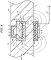
Fig. 4 is a cross-sectional view illustrating a connection state of a first transmission/reception unit and a second transmission/reception unit of the sensor system inFig. 1 . -
Fig. 5A is a plan view illustrating a configuration example of a medical device provided with the sensor system inFig. 1 , andFig. 5B is a plan view illustrating another configuration example of the medical device provided with the sensor system inFig. 1 . - Preferred embodiments of the present invention are hereinafter described in detail with reference to the accompanying drawings.
- A
sensor system 10 according to this embodiment is attached to ablood flow path 14 of a disposable medical device such as an artificial lung and a dialysis device, and is used for detecting an abnormality of the medical device. - As illustrated in
Fig. 1 , thesensor system 10 is provided with a first transmission/reception unit 16 provided inside amedical instrument 12 including theblood flow path 14, and a second transmission/reception unit 18 attached outside themedical instrument 12. The first transmission/reception unit 16 and the second transmission/reception unit 18 are configured to supply power and transmit/receive signals in a contactless manner without wiring. - The first transmission/
reception unit 16 is provided with asensor unit 22, asemiconductor substrate 28, and a substrate with built-in coil 42. Thesensor unit 22 is provided with a piezoresistancesemiconductor pressure sensor 22a with acavity 24 inside, thecavity 24 kept in a vacuum state and capable of detecting an absolute pressure. As a result, it is possible to eliminate the necessity of calibration work in each measurement. Thesensor unit 22 is such that an upper end portion is distorted toward thecavity 24 according to a pressure difference between thecavity 24 and the outside, thereby indicating a change in resistance value according to an external pressure. Thesensor unit 22 is further provided with a sensor amplifier that converts a resistance change of the piezoresistancesemiconductor pressure sensor 22a into a voltage value to output. Thesensor unit 22 including the sensor amplifier and the piezoresistancesemiconductor pressure sensor 22a is joined to aprincipal surface 28a (upper surface) of thesemiconductor substrate 28. Thesensor unit 22 and thesemiconductor substrate 28 are covered with aprotective layer 26 made of resin and the like. - As illustrated in
Fig. 2 , an A/D converter 23 and a transmission/reception circuit 25 are formed on thesemiconductor substrate 28. The A/D converter 23 is electrically connected to thesensor unit 22 and the transmission/reception circuit 25, converts an output voltage of the sensor amplifier of thesensor unit 22 into a digital signal, and outputs the same to the transmission/reception circuit 25. The transmission/reception circuit 25 is electrically connected to afirst coil 32. The transmission/reception circuit 25 converts electric power supplied via thefirst coil 32 into a predetermined voltage and supplies the same to thesensor unit 22 and the A/D converter 23. The transmission/reception circuit 25 also modulates the digital signal received from the A/D converter 23 into a signal of a predetermined frequency, and transmits the same to the second transmission/reception unit 18 via thefirst coil 32. The A/D converter 23 and the transmission/reception circuit 25 are formed on theprincipal surface 28a (upper surface) or a lower surface of thesemiconductor substrate 28 by a semiconductor manufacturing process. - As illustrated in
Fig. 1 , the substrate with built-incoil 42 is joined to the lower surface side of thesemiconductor substrate 28. The substrate with built-in coil 42 is formed of a multilayer substrate in which a plurality ofresin layers first coil 32 formed into a planar shape is embedded between theresin layers first coil 32 is formed flat in a direction parallel to principal surfaces of thesemiconductor substrate 28 and the substrate with built-incoil 42, and a winding axis of thefirst coil 32 is in a direction perpendicular to thesemiconductor substrate 28 and the substrate with built-incoil 42. Thefirst coil 32 is formed on theresin layer 41a, for example, as a spiral conductor pattern. - The substrate with built-
in coil 42 including thefirst coil 32 is manufactured by, for example, a build-up method and the like. Avia hole 41c that penetrates theresin layer 41b in a thickness direction is formed at one end and the other end of thefirst coil 32. Aconductor 32a such as copper is embedded in thevia hole 41c. Thefirst coil 32 is electrically connected to thesemiconductor substrate 28 via theconductor 32a embedded in thevia hole 41c. - The first transmission/
reception unit 16 is arranged so that thesensor unit 22 is adjacent to theblood flow path 14. In this embodiment, as illustrated in the drawing, the first transmission/reception unit 16 is accommodated in arecess 12b formed on aside wall 12a of the medical instrument 12 (tube) including theblood flow path 14. Note that, from the viewpoint of preventing occurrence of thrombus, the first transmission/reception unit 16 is preferably attached inside themedical instrument 12 so as not to protrude from aninner wall 12c of themedical instrument 12. That is, this is preferably arranged so that an upper end of thesensor unit 22 of the first transmission/reception unit 16 is flush with theinner wall 12c of themedical instrument 12. - In the first transmission/
reception unit 16 described above, the substrate with built-incoil 42 may be formed into a rectangular shape of, for example, about 2 mm square to 5 mm square. The larger an area of the substrate with built-in coil 42, the larger an area of thefirst coil 32, so that power supply from the second transmission/reception unit 18 and signal transmission/reception become easier. Thesemiconductor substrate 28 may have a size equivalent to or smaller than that of the substrate with built-incoil 42. - The second transmission/
reception unit 18 is provided with asecond coil 36, acoil substrate 44, acircuit element 46, andconnection wiring 52. Thecoil substrate 44 is a substrate made of a resin alone or a fiber reinforced resin, or ceramics, on one surface of which thesecond coil 36 planarly wound as a spiral pattern is formed. Thesecond coil 36 is planarly formed along a principal surface of thecoil substrate 44, and a winding axis thereof is in a direction perpendicular to thecoil substrate 44. Thesecond coil 36 and thecoil substrate 44 are covered with acoating resin 45. - The
circuit element 46 is mounted on the other surface of thecoil substrate 44. As illustrated inFig. 2 , thecircuit element 46 is provided with a transmission/reception circuit 38 and an input/output unit 40. The transmission/reception circuit 38 is electrically connected to thesecond coil 36, supplies electric power for driving thesecond coil 36, and receives a detection signal of the first transmission/reception unit 16 via thesecond coil 36. The input/output unit 40 is connected to acontrol device 20 via theconnection wiring 52. The input/output unit 40 is configured to receive a control signal from thecontrol device 20 and transmit measurement data of the first transmission/reception unit 16 to thecontrol device 20. - The transmission/
reception circuit 38 and the input/output unit 40 of thecircuit element 46 may be formed on the same semiconductor chip, or formed on different semiconductor chips to be electrically connected on thecoil substrate 44. Lower surfaces of thecircuit element 46 and thecoil substrate 44 are covered with aresin layer 47. - The
connection wiring 52 includes a plurality of conductor wires and supplies electric power required for an operation of the second transmission/reception unit 18. Theconnection wiring 52 is configured to transmit a signal between thecontrol device 20 and the second transmission/reception unit 18. - The second transmission/
reception unit 18 described above is detachably arranged in a direction in which thesecond coil 36 is parallel to thefirst coil 32, in a position in which thesecond coil 36 is opposed to thefirst coil 32. Note that, the direction in which thesecond coil 36 is parallel to thefirst coil 32 is not limited to the direction in which thesecond coil 36 is strictly parallel to thefirst coil 32, but also includes a case where thesecond coil 36 is slightly inclined with respect to thefirst coil 32. That is, thesecond coil 36 may be inclined within a range in which thefirst coil 32 may generate electric power required for an operation of the first transmission/reception unit 16. - An operation of the
sensor system 10 is described below. - The
sensor system 10 operates so as to detect a pressure of theblood flow path 14 of themedical instrument 12 at a predetermined sampling frequency. The sampling frequency may be set to, for example, 10 Hz. As illustrated inFig. 3 , first, at step S10, the second transmission/reception unit 18 starts generating an electromagnetic field based on a measurement start signal. Here, the measurement start signal is transmitted from thecontrol device 20 to the second transmission/reception unit 18 via theconnection wiring 52 every sampling cycle. - When receiving the measurement start signal via the input/
output unit 40, the transmission/reception circuit 38 supplies an alternating current of a predetermined frequency to thesecond coil 36 to generate the electromagnetic field of a predetermined frequency from thesecond coil 36. Although not especially limited, the frequency of the electromagnetic field generated by thesecond coil 36 may be set to, for example, about 135 kHz. Thesecond coil 36 continuously generates the electromagnetic field until the reception of the measurement start signal from the second transmission/reception unit 18 is completed. - Next, at step S12, the first transmission/
reception unit 16 receives the electromagnetic field of thesecond coil 36 to be activated. As illustrated inFig. 4 , amagnetic flux 50 is generated around thesecond coil 36 by the alternating current flowing in thesecond coil 36. An alternating current is generated in thefirst coil 32 by electromagnetic induction via themagnetic flux 50. The alternating current generated in thefirst coil 32 is converted into DC power of a predetermined voltage by the transmission/reception circuit 25 provided on thesemiconductor substrate 28, and the electric power is supplied to the A/D converter 23 and thesensor unit 22. As a result, the first transmission/reception unit 16 is activated. - Next, at step S14 in
Fig. 3 , the first transmission/reception unit 16 obtains a detection value of thesensor unit 22. That is, thesensor unit 22 outputs a voltage value corresponding to a pressure difference between the piezoresistancesemiconductor pressure sensor 22a and thecavity 24 to the A/D converter 23. The A/D converter 23 converts the output voltage of thesensor unit 22 into the digital signal and transmits the same to the transmission/reception circuit 25. - Next, at step S16, the first transmission/
reception unit 16 transmits the detection value of thesensor unit 22. That is, the transmission/reception circuit 25 of the first transmission/reception unit 16 modulates the digital signal to a predetermined frequency and transmits the same from thefirst coil 32. - Next, at step S18, the second transmission/
reception unit 18 receives the detection value of thesensor unit 22. A transmission signal of the first transmission/reception unit 16 is received by the transmission/reception circuit 38 of the second transmission/reception unit 18 via thesecond coil 36 by electromagnetic induction. - Next, at step S20, the second transmission/
reception unit 18 outputs the detection value of thesensor unit 22 to thecontrol device 20. That is, the detection signal received by the transmission/reception circuit 38 is input to the input/output unit 40, converted into a predetermined data format, and then transmitted to thecontrol device 20 via theconnection wiring 52. - After that, at step S22, the second transmission/
reception unit 18 stops generating the electromagnetic field via thesecond coil 36. As described above, the operation of thesensor system 10 in one sampling is completed. Thesensor system 10 repeatedly performs the operation at steps S10 to S22 described above every sampling cycle. - As illustrated in
Fig. 5A , thesensor system 10 may be used in amedical device 60. Themedical device 60 is provided with ablood pump 62 and the medical instrument 12 (tube) connected to an inlet or outlet of theblood pump 62. The first transmission/reception unit 16 is provided inside the medical instrument 12 (tube). The second transmission/reception unit 18 is detachably attached to outside the medical instrument 12 (tube). The medical instrument 12 (tube) is provided with aguide unit 12s formed of a groove or a recess for attaching the second transmission/reception unit 18 in a predetermined position. As illustrated in the drawing, by attaching the second transmission/reception unit 18 to theguide unit 12s, an inner pressure of themedical device 60 may be measured. - As illustrated in
Fig. 5B , in amedical device 60A, the medical instrument 12 (tube) is connected to the inlet and the outlet of theblood pump 62. The first transmission/reception unit 16 is provided inside each medical instrument 12 (tube). In such a case, in a case where it is not required to measure a pressure at a plurality of sites on the sameblood flow path 14, the second transmission/reception unit 18 is attached to one of the first transmission/reception units 16. In this manner, since it is possible to attach the second transmission/reception unit 18 only to a necessary portion, theconnection wiring 52 may be minimized. Therefore, in themedical device 60A, theconnection wiring 52 is simplified and handleability in a medical setting is improved. - The
sensor system 10 and themedical devices - The
sensor system 10 is provided with the first transmission/reception unit 16 incorporated inside themedical instrument 12 to output the detection signal of thesensor unit 22, and the second transmission/reception unit 18 configured to be removably attached to themedical instrument 12 to transmit/receive the signal to and from the first transmission/reception unit 16 in a contactless manner, in which the first transmission/reception unit 16 and the second transmission/reception unit 18 are configured to be arranged so as to be opposed to each other across themedical instrument 12 to transmit/receive the signal by electromagnetic induction. The first transmission/reception unit 16 provided so as to face theblood flow path 14 and the second transmission/reception unit 18 attached outside themedical instrument 12 are connected to each other in a contactless manner by electromagnetic induction. As a result, electrical safety of themedical device 60 may be secured. - In the above-described
sensor system 10, the first transmission/reception unit 16 is provided with the semiconductor substrate 28 (substrate), thesensor unit 22 mounted on thesemiconductor substrate 28 and arranged at a site in contact with theblood flow path 14 of themedical instrument 12 including theblood flow path 14, and thefirst coil 32 wound in the direction parallel to theprincipal surface 28a of thesemiconductor substrate 28. With this configuration, the first transmission/reception unit 16 may be made thinner and smaller. As a result, the first transmission/reception unit 16 may also be provided inside a narrowmedical instrument 12 such as a tube. - In the above-described
sensor system 10, the second transmission/reception unit 18 includes the planarly woundsecond coil 36, and the first transmission/reception unit 16 and the second transmission/reception unit 18 are arranged so as to be opposed to each other so that the winding axis of thefirst coil 32 is parallel to the winding axis of thesecond coil 36. This facilitates electromagnetic induction between thefirst coil 32 and thesecond coil 36. - In the above-described
sensor system 10, the second transmission/reception unit 18 may supply drive power to the first transmission/reception unit 16 by current induction. As a result, it becomes possible to operate the first transmission/reception unit 16 without providing a storage battery and power supply wiring on the first transmission/reception unit 16. - In the above-described
sensor system 10, the first transmission/reception unit 16 may be configured to transmit the detection signal of thesensor unit 22 to the second transmission/reception unit 18 by electromagnetic induction. With this configuration, a device configuration may be made simple and the second transmission/reception unit 18 may be made smaller. - In the above-described
sensor system 10, thesensor unit 22 may be the piezoresistancesemiconductor pressure sensor 22a (pressure sensor) that detects a pressure of the blood flowing in theblood flow path 14. As a result, it is possible to detect an abnormality due to obstruction of theblood flow path 14 and the like. - In the above-described
sensor system 10, theguide unit 12s that indicates an installation position of the first transmission/reception unit 16 may be provided outside themedical instrument 12. With this configuration, the second transmission/reception unit 18 may be attached in an appropriate position. - In the above-described
sensor system 10, the first transmission/reception unit 16 may be attached inside themedical instrument 12 so that the upper end portion thereof does not protrude from theinner wall 12c of theblood flow path 14. This makes it possible to prevent occurrence of thrombus in theblood flow path 14. - The above-described
medical devices sensor system 10 provided with themedical instrument 12 including theblood flow path 14, the first transmission/reception unit 16 incorporated inside theblood flow path 14 of themedical instrument 12 to output the detection signal of thesensor unit 22 that detects, and the second transmission/reception unit 18 configured to be removably attached to themedical instrument 12 to transmit/receive the signal to and from the first transmission/reception unit 16 in a contactless manner, in which the first transmission/reception unit 16 and the second transmission/reception unit 18 are arranged so as to be opposed to each other across themedical instrument 12 to transmit/receive the signal by electromagnetic induction. As a result, electrical safety of themedical devices reception unit 18 may be detached in a case where it is not required to measure, theconnection wiring 52 is simplified and handleability of themedical devices - The sensor system and the medical device are described above with reference to the preferable embodiment, but the sensor system and the medical device are not limited to the above-described embodiment, and it goes without saying that various modifications may be made without departing from the gist of the present invention. For example, the pressure sensor using the piezoresistance
semiconductor pressure sensor 22a is described as an example of thesensor unit 22, but there is no limitation. Thesensor unit 22 may be a temperature sensor that detects temperature of the blood, or may include an electrochemical sensor that detects a predetermined blood component by an electrochemical reaction with the blood. Thesensor unit 22 may also be a sensor that detects various characteristics such as magnetic characteristics, optical characteristics, and viscosity of the blood.
Claims (9)
- A sensor system comprising:a first transmission/reception unit incorporated inside a medical instrument configured to output a detection signal of a sensor unit; anda second transmission/reception unit configured to be removably attached to the medical instrument and transmit/receive a signal to and from the first transmission/reception unit in a contactless manner, whereinthe first transmission/reception unit and the second transmission/reception unit are configured to be arranged so as to be opposed to each other across the medical instrument and transmit/receive the signal by electromagnetic induction.
- The sensor system according to claim 1, whereinthe first transmission/reception unit is provided with a substrate,a sensor unit mounted on the semiconductor and arranged at a site in contact with a blood flow path of the medical instrument including the blood flow path, anda first coil wound in a direction parallel to a principal surface of the substrate.
- The sensor system according to claim 2, wherein
the second transmission/reception unit includes a planarly wound second coil, and the first transmission/reception unit and the second transmission/reception unit are arranged so as to be opposed to each other so that a winding axis of the first coil is parallel to a winding axis of the second coil. - The sensor system according to claim 3, wherein
the second transmission/reception unit supplies drive power to the first transmission/reception unit by current induction. - The sensor system according to claim 4, wherein
the first transmission/reception unit transmits a detection signal of the sensor unit to the second transmission/reception unit by electromagnetic induction. - The sensor system according to any one of claims 2 to 5, wherein
the sensor unit is a pressure sensor that detects a pressure of blood that flows in the blood flow path. - The sensor system according to any one of claims 1 to 6, wherein
a guide unit that indicates an installation position of the first transmission/reception unit is provided outside the medical instrument. - The sensor system according to claim 2, wherein
the first transmission/reception unit is attached inside the medical instrument so that an upper end portion of the first transmission/reception unit does not protrude from an inner wall of the blood flow path. - A medical device comprising:a medical instrument including a blood flow path; anda sensor system provided with a first transmission/reception unit incorporated inside the blood flow path of the medical instrument configured to output a detection signal of a sensor unit, and a second transmission/reception unit configured to be removably attached to the medical instrument and transmit/receive a signal to and from the first transmission/reception unit in a contactless manner, in which the first transmission/reception unit and the second transmission/reception unit are configured to be arranged so as to be opposed to each other across the medical instrument and transmit/receive the signal by electromagnetic induction.
Applications Claiming Priority (2)
| Application Number | Priority Date | Filing Date | Title |
|---|---|---|---|
| JP2019041317 | 2019-03-07 | ||
| PCT/JP2020/005753 WO2020179411A1 (en) | 2019-03-07 | 2020-02-14 | Sensor system and medical device |
Publications (2)
| Publication Number | Publication Date |
|---|---|
| EP3919096A1 true EP3919096A1 (en) | 2021-12-08 |
| EP3919096A4 EP3919096A4 (en) | 2022-04-13 |
Family
ID=72338270
Family Applications (1)
| Application Number | Title | Priority Date | Filing Date |
|---|---|---|---|
| EP20766359.2A Pending EP3919096A4 (en) | 2019-03-07 | 2020-02-14 | SENSOR SYSTEM AND MEDICAL DEVICE |
Country Status (4)
| Country | Link |
|---|---|
| US (1) | US12311094B2 (en) |
| EP (1) | EP3919096A4 (en) |
| JP (1) | JP7422733B2 (en) |
| WO (1) | WO2020179411A1 (en) |
Family Cites Families (9)
| Publication number | Priority date | Publication date | Assignee | Title |
|---|---|---|---|---|
| JPH0346729Y2 (en) * | 1987-04-06 | 1991-10-03 | ||
| SE0400330D0 (en) * | 2004-02-12 | 2004-02-12 | Gambro Lundia Ab | Pressure sensing |
| US9636487B2 (en) * | 2010-06-17 | 2017-05-02 | University Of Virginia Patent Foundation | Meters for in-vivo monitoring |
| WO2012112819A2 (en) * | 2011-02-16 | 2012-08-23 | Alfred E. Mann Foundation For Scientific Research | Implantable shunt system and associated pressure sensors |
| US9649481B2 (en) * | 2013-03-14 | 2017-05-16 | Siddharth Sadanand | Shunt flow monitor |
| EP2916120A1 (en) * | 2014-03-04 | 2015-09-09 | seleon GmbH | Sensor block, tube and manufacturing method |
| US10226193B2 (en) | 2015-03-31 | 2019-03-12 | Medtronic Ps Medical, Inc. | Wireless pressure measurement and monitoring for shunts |
| CN108093659B (en) * | 2015-09-03 | 2021-09-14 | 皇家飞利浦有限公司 | Connector and device for wireless transmission of data and power |
| JP6857095B2 (en) * | 2017-07-05 | 2021-04-14 | サーパス工業株式会社 | Pressure detector |
-
2020
- 2020-02-14 EP EP20766359.2A patent/EP3919096A4/en active Pending
- 2020-02-14 JP JP2021503513A patent/JP7422733B2/en active Active
- 2020-02-14 WO PCT/JP2020/005753 patent/WO2020179411A1/en not_active Ceased
-
2021
- 2021-08-12 US US17/400,558 patent/US12311094B2/en active Active
Also Published As
| Publication number | Publication date |
|---|---|
| EP3919096A4 (en) | 2022-04-13 |
| US12311094B2 (en) | 2025-05-27 |
| US20210369935A1 (en) | 2021-12-02 |
| JPWO2020179411A1 (en) | 2020-09-10 |
| WO2020179411A1 (en) | 2020-09-10 |
| JP7422733B2 (en) | 2024-01-26 |
Similar Documents
| Publication | Publication Date | Title |
|---|---|---|
| US8360984B2 (en) | Hypertension system and method | |
| EP0601046B1 (en) | Apparatus for transmitting instrumentation signals over power conductors | |
| US20100176904A1 (en) | Current detection printed board, voltage detection printed board, and current/voltage detector using same, and current detector and voltage detector | |
| KR101559215B1 (en) | Biosensor package and packaging method thereof | |
| EP3321781A1 (en) | Position indicator | |
| KR101969575B1 (en) | Leak liquid sensing device | |
| CN108140477A (en) | For the stackable connector and device of electric power wireless transmission | |
| CN101765779B (en) | Diagnosis device for signal status during measurement and control performed by a measurement unit or control unit | |
| EP2869043B1 (en) | Hybrid connection device | |
| KR101884905B1 (en) | Leak liquid sensing device and manufacturing method the same | |
| US12311094B2 (en) | Sensor system and medical device | |
| US20170188954A1 (en) | Interface unit and a measurement system | |
| CN104246451A (en) | Flow meter, measuring tube, and method for producing a flow meter | |
| US20240170409A1 (en) | Semiconductor module, semiconductor chip, and method for manufacturing semiconductor module | |
| JP2011047688A (en) | Pressure sensing element and pressure sensor | |
| US12259410B2 (en) | Rogowski-type current sensor and inverter, and method of mounting Rogowski-type current sensor | |
| JP2014066681A (en) | High frequency detection device, and high frequency measurement apparatus with the same | |
| WO2004026129A1 (en) | System for read-out of pressure | |
| EA038680B1 (en) | Medical device for guiding fluids received in or coupled with a blood treatment apparatus | |
| CN219714490U (en) | Ultrasonic liquid level detection module and system | |
| CN105556255A (en) | A device for fault detection and/or identification of at least one sensor device | |
| KR101552777B1 (en) | Biosensor package and packaging method thereof | |
| EP4053529B1 (en) | A device for measuring water pressure in soil pores comprising a pressure gauge | |
| KR20170006528A (en) | Apparatus for sensing torque | |
| JP6106074B2 (en) | Pressure gauge for differential pressure measurement |
Legal Events
| Date | Code | Title | Description |
|---|---|---|---|
| STAA | Information on the status of an ep patent application or granted ep patent |
Free format text: STATUS: THE INTERNATIONAL PUBLICATION HAS BEEN MADE |
|
| PUAI | Public reference made under article 153(3) epc to a published international application that has entered the european phase |
Free format text: ORIGINAL CODE: 0009012 |
|
| STAA | Information on the status of an ep patent application or granted ep patent |
Free format text: STATUS: REQUEST FOR EXAMINATION WAS MADE |
|
| 17P | Request for examination filed |
Effective date: 20210831 |
|
| AK | Designated contracting states |
Kind code of ref document: A1 Designated state(s): AL AT BE BG CH CY CZ DE DK EE ES FI FR GB GR HR HU IE IS IT LI LT LU LV MC MK MT NL NO PL PT RO RS SE SI SK SM TR |
|
| A4 | Supplementary search report drawn up and despatched |
Effective date: 20220314 |
|
| RIC1 | Information provided on ipc code assigned before grant |
Ipc: G01L 19/08 20060101ALI20220308BHEP Ipc: G01L 9/00 20060101ALI20220308BHEP Ipc: A61M 1/14 20060101ALI20220308BHEP Ipc: A61M 1/36 20060101ALI20220308BHEP Ipc: A61M 1/16 20060101AFI20220308BHEP |
|
| DAV | Request for validation of the european patent (deleted) | ||
| DAX | Request for extension of the european patent (deleted) | ||
| STAA | Information on the status of an ep patent application or granted ep patent |
Free format text: STATUS: EXAMINATION IS IN PROGRESS |
|
| 17Q | First examination report despatched |
Effective date: 20240911 |