EP3918031B1 - Système d'amélioration de gaz synthétique produit à partir de déchets, de déchets solides municipaux ou de biomasse - Google Patents
Système d'amélioration de gaz synthétique produit à partir de déchets, de déchets solides municipaux ou de biomasse Download PDFInfo
- Publication number
- EP3918031B1 EP3918031B1 EP20749183.8A EP20749183A EP3918031B1 EP 3918031 B1 EP3918031 B1 EP 3918031B1 EP 20749183 A EP20749183 A EP 20749183A EP 3918031 B1 EP3918031 B1 EP 3918031B1
- Authority
- EP
- European Patent Office
- Prior art keywords
- thermal
- chamber
- fuel
- synthetic gas
- stream
- Prior art date
- Legal status (The legal status is an assumption and is not a legal conclusion. Google has not performed a legal analysis and makes no representation as to the accuracy of the status listed.)
- Active
Links
- 239000002699 waste material Substances 0.000 title claims description 14
- 239000010813 municipal solid waste Substances 0.000 title claims description 9
- 239000002028 Biomass Substances 0.000 title claims description 7
- 239000000446 fuel Substances 0.000 claims description 108
- 238000000197 pyrolysis Methods 0.000 claims description 100
- 239000007789 gas Substances 0.000 claims description 95
- 238000002309 gasification Methods 0.000 claims description 77
- 239000003054 catalyst Substances 0.000 claims description 43
- QVGXLLKOCUKJST-UHFFFAOYSA-N atomic oxygen Chemical compound [O] QVGXLLKOCUKJST-UHFFFAOYSA-N 0.000 claims description 32
- 239000001301 oxygen Substances 0.000 claims description 32
- 229910052760 oxygen Inorganic materials 0.000 claims description 32
- 238000007254 oxidation reaction Methods 0.000 claims description 26
- UGFAIRIUMAVXCW-UHFFFAOYSA-N Carbon monoxide Chemical compound [O+]#[C-] UGFAIRIUMAVXCW-UHFFFAOYSA-N 0.000 claims description 23
- 230000003197 catalytic effect Effects 0.000 claims description 23
- 239000003546 flue gas Substances 0.000 claims description 23
- 239000000203 mixture Substances 0.000 claims description 22
- 238000010438 heat treatment Methods 0.000 claims description 20
- 230000003647 oxidation Effects 0.000 claims description 20
- 238000000605 extraction Methods 0.000 claims description 7
- 238000004891 communication Methods 0.000 claims description 6
- 239000012263 liquid product Substances 0.000 claims description 6
- 239000000126 substance Substances 0.000 claims description 5
- 230000007246 mechanism Effects 0.000 claims description 4
- 239000004449 solid propellant Substances 0.000 claims description 4
- 238000011144 upstream manufacturing Methods 0.000 claims description 3
- 238000000034 method Methods 0.000 description 32
- 239000007788 liquid Substances 0.000 description 27
- 239000000463 material Substances 0.000 description 27
- 230000008569 process Effects 0.000 description 26
- 239000007800 oxidant agent Substances 0.000 description 24
- 238000006243 chemical reaction Methods 0.000 description 17
- 150000002430 hydrocarbons Chemical class 0.000 description 12
- VNWKTOKETHGBQD-UHFFFAOYSA-N methane Chemical compound C VNWKTOKETHGBQD-UHFFFAOYSA-N 0.000 description 12
- OKTJSMMVPCPJKN-UHFFFAOYSA-N Carbon Chemical compound [C] OKTJSMMVPCPJKN-UHFFFAOYSA-N 0.000 description 10
- 239000007787 solid Substances 0.000 description 10
- 239000007921 spray Substances 0.000 description 10
- 229910052799 carbon Inorganic materials 0.000 description 8
- 230000008859 change Effects 0.000 description 7
- 239000002737 fuel gas Substances 0.000 description 7
- 239000012071 phase Substances 0.000 description 7
- 239000000047 product Substances 0.000 description 7
- IJGRMHOSHXDMSA-UHFFFAOYSA-N Atomic nitrogen Chemical compound N#N IJGRMHOSHXDMSA-UHFFFAOYSA-N 0.000 description 6
- 229930195733 hydrocarbon Natural products 0.000 description 6
- 239000003345 natural gas Substances 0.000 description 6
- 239000004033 plastic Substances 0.000 description 6
- 229920003023 plastic Polymers 0.000 description 6
- 238000010791 quenching Methods 0.000 description 6
- 238000002485 combustion reaction Methods 0.000 description 5
- 239000000356 contaminant Substances 0.000 description 5
- 239000012530 fluid Substances 0.000 description 5
- 239000011521 glass Substances 0.000 description 5
- 239000002184 metal Substances 0.000 description 5
- 229910052751 metal Inorganic materials 0.000 description 5
- 238000012545 processing Methods 0.000 description 5
- 238000000926 separation method Methods 0.000 description 5
- QGZKDVFQNNGYKY-UHFFFAOYSA-N Ammonia Chemical compound N QGZKDVFQNNGYKY-UHFFFAOYSA-N 0.000 description 4
- 239000004215 Carbon black (E152) Substances 0.000 description 4
- VYPSYNLAJGMNEJ-UHFFFAOYSA-N Silicium dioxide Chemical compound O=[Si]=O VYPSYNLAJGMNEJ-UHFFFAOYSA-N 0.000 description 4
- 238000004519 manufacturing process Methods 0.000 description 4
- 150000002739 metals Chemical class 0.000 description 4
- 238000004227 thermal cracking Methods 0.000 description 4
- 238000012546 transfer Methods 0.000 description 4
- XLYOFNOQVPJJNP-UHFFFAOYSA-N water Chemical compound O XLYOFNOQVPJJNP-UHFFFAOYSA-N 0.000 description 4
- 238000003763 carbonization Methods 0.000 description 3
- 238000004523 catalytic cracking Methods 0.000 description 3
- 229910052757 nitrogen Inorganic materials 0.000 description 3
- 230000001590 oxidative effect Effects 0.000 description 3
- 238000011084 recovery Methods 0.000 description 3
- 238000002407 reforming Methods 0.000 description 3
- 238000005201 scrubbing Methods 0.000 description 3
- 239000011343 solid material Substances 0.000 description 3
- 239000001993 wax Substances 0.000 description 3
- 229910021529 ammonia Inorganic materials 0.000 description 2
- 230000015572 biosynthetic process Effects 0.000 description 2
- 239000000571 coke Substances 0.000 description 2
- 150000001875 compounds Chemical class 0.000 description 2
- 238000005336 cracking Methods 0.000 description 2
- 239000003921 oil Substances 0.000 description 2
- 239000011368 organic material Substances 0.000 description 2
- 230000004044 response Effects 0.000 description 2
- 229920006395 saturated elastomer Polymers 0.000 description 2
- 239000010801 sewage sludge Substances 0.000 description 2
- 239000000377 silicon dioxide Substances 0.000 description 2
- 238000003860 storage Methods 0.000 description 2
- UFHFLCQGNIYNRP-UHFFFAOYSA-N Hydrogen Chemical compound [H][H] UFHFLCQGNIYNRP-UHFFFAOYSA-N 0.000 description 1
- 230000009471 action Effects 0.000 description 1
- 230000009286 beneficial effect Effects 0.000 description 1
- 238000009835 boiling Methods 0.000 description 1
- 239000003575 carbonaceous material Substances 0.000 description 1
- 230000015556 catabolic process Effects 0.000 description 1
- 238000011109 contamination Methods 0.000 description 1
- 230000001276 controlling effect Effects 0.000 description 1
- 230000007423 decrease Effects 0.000 description 1
- 238000006731 degradation reaction Methods 0.000 description 1
- 238000010586 diagram Methods 0.000 description 1
- 238000007865 diluting Methods 0.000 description 1
- 239000003085 diluting agent Substances 0.000 description 1
- 239000010791 domestic waste Substances 0.000 description 1
- 238000001035 drying Methods 0.000 description 1
- 230000000694 effects Effects 0.000 description 1
- 230000005611 electricity Effects 0.000 description 1
- 238000001125 extrusion Methods 0.000 description 1
- 238000010304 firing Methods 0.000 description 1
- 230000005484 gravity Effects 0.000 description 1
- 239000001257 hydrogen Substances 0.000 description 1
- 229910052739 hydrogen Inorganic materials 0.000 description 1
- 239000004615 ingredient Substances 0.000 description 1
- 239000007791 liquid phase Substances 0.000 description 1
- 238000012544 monitoring process Methods 0.000 description 1
- 238000010248 power generation Methods 0.000 description 1
- 230000003134 recirculating effect Effects 0.000 description 1
- 230000009467 reduction Effects 0.000 description 1
- 230000001105 regulatory effect Effects 0.000 description 1
- 239000000523 sample Substances 0.000 description 1
- 238000005549 size reduction Methods 0.000 description 1
- 238000000629 steam reforming Methods 0.000 description 1
- 230000002459 sustained effect Effects 0.000 description 1
- 238000003786 synthesis reaction Methods 0.000 description 1
- 239000011269 tar Substances 0.000 description 1
- 239000012808 vapor phase Substances 0.000 description 1
- 238000009834 vaporization Methods 0.000 description 1
- 230000008016 vaporization Effects 0.000 description 1
Images


Classifications
-
- C—CHEMISTRY; METALLURGY
- C10—PETROLEUM, GAS OR COKE INDUSTRIES; TECHNICAL GASES CONTAINING CARBON MONOXIDE; FUELS; LUBRICANTS; PEAT
- C10L—FUELS NOT OTHERWISE PROVIDED FOR; NATURAL GAS; SYNTHETIC NATURAL GAS OBTAINED BY PROCESSES NOT COVERED BY SUBCLASSES C10G, C10K; LIQUEFIED PETROLEUM GAS; ADDING MATERIALS TO FUELS OR FIRES TO REDUCE SMOKE OR UNDESIRABLE DEPOSITS OR TO FACILITATE SOOT REMOVAL; FIRELIGHTERS
- C10L3/00—Gaseous fuels; Natural gas; Synthetic natural gas obtained by processes not covered by subclass C10G, C10K; Liquefied petroleum gas
- C10L3/06—Natural gas; Synthetic natural gas obtained by processes not covered by C10G, C10K3/02 or C10K3/04
- C10L3/08—Production of synthetic natural gas
-
- C—CHEMISTRY; METALLURGY
- C10—PETROLEUM, GAS OR COKE INDUSTRIES; TECHNICAL GASES CONTAINING CARBON MONOXIDE; FUELS; LUBRICANTS; PEAT
- C10J—PRODUCTION OF PRODUCER GAS, WATER-GAS, SYNTHESIS GAS FROM SOLID CARBONACEOUS MATERIAL, OR MIXTURES CONTAINING THESE GASES; CARBURETTING AIR OR OTHER GASES
- C10J3/00—Production of combustible gases containing carbon monoxide from solid carbonaceous fuels
- C10J3/002—Horizontal gasifiers, e.g. belt-type gasifiers
-
- C—CHEMISTRY; METALLURGY
- C10—PETROLEUM, GAS OR COKE INDUSTRIES; TECHNICAL GASES CONTAINING CARBON MONOXIDE; FUELS; LUBRICANTS; PEAT
- C10B—DESTRUCTIVE DISTILLATION OF CARBONACEOUS MATERIALS FOR PRODUCTION OF GAS, COKE, TAR, OR SIMILAR MATERIALS
- C10B47/00—Destructive distillation of solid carbonaceous materials with indirect heating, e.g. by external combustion
- C10B47/02—Destructive distillation of solid carbonaceous materials with indirect heating, e.g. by external combustion with stationary charge
- C10B47/06—Destructive distillation of solid carbonaceous materials with indirect heating, e.g. by external combustion with stationary charge in retorts
-
- C—CHEMISTRY; METALLURGY
- C10—PETROLEUM, GAS OR COKE INDUSTRIES; TECHNICAL GASES CONTAINING CARBON MONOXIDE; FUELS; LUBRICANTS; PEAT
- C10B—DESTRUCTIVE DISTILLATION OF CARBONACEOUS MATERIALS FOR PRODUCTION OF GAS, COKE, TAR, OR SIMILAR MATERIALS
- C10B49/00—Destructive distillation of solid carbonaceous materials by direct heating with heat-carrying agents including the partial combustion of the solid material to be treated
- C10B49/02—Destructive distillation of solid carbonaceous materials by direct heating with heat-carrying agents including the partial combustion of the solid material to be treated with hot gases or vapours, e.g. hot gases obtained by partial combustion of the charge
- C10B49/04—Destructive distillation of solid carbonaceous materials by direct heating with heat-carrying agents including the partial combustion of the solid material to be treated with hot gases or vapours, e.g. hot gases obtained by partial combustion of the charge while moving the solid material to be treated
-
- C—CHEMISTRY; METALLURGY
- C10—PETROLEUM, GAS OR COKE INDUSTRIES; TECHNICAL GASES CONTAINING CARBON MONOXIDE; FUELS; LUBRICANTS; PEAT
- C10B—DESTRUCTIVE DISTILLATION OF CARBONACEOUS MATERIALS FOR PRODUCTION OF GAS, COKE, TAR, OR SIMILAR MATERIALS
- C10B53/00—Destructive distillation, specially adapted for particular solid raw materials or solid raw materials in special form
-
- C—CHEMISTRY; METALLURGY
- C10—PETROLEUM, GAS OR COKE INDUSTRIES; TECHNICAL GASES CONTAINING CARBON MONOXIDE; FUELS; LUBRICANTS; PEAT
- C10B—DESTRUCTIVE DISTILLATION OF CARBONACEOUS MATERIALS FOR PRODUCTION OF GAS, COKE, TAR, OR SIMILAR MATERIALS
- C10B57/00—Other carbonising or coking processes; Features of destructive distillation processes in general
- C10B57/02—Multi-step carbonising or coking processes
-
- C—CHEMISTRY; METALLURGY
- C10—PETROLEUM, GAS OR COKE INDUSTRIES; TECHNICAL GASES CONTAINING CARBON MONOXIDE; FUELS; LUBRICANTS; PEAT
- C10G—CRACKING HYDROCARBON OILS; PRODUCTION OF LIQUID HYDROCARBON MIXTURES, e.g. BY DESTRUCTIVE HYDROGENATION, OLIGOMERISATION, POLYMERISATION; RECOVERY OF HYDROCARBON OILS FROM OIL-SHALE, OIL-SAND, OR GASES; REFINING MIXTURES MAINLY CONSISTING OF HYDROCARBONS; REFORMING OF NAPHTHA; MINERAL WAXES
- C10G11/00—Catalytic cracking, in the absence of hydrogen, of hydrocarbon oils
- C10G11/20—Catalytic cracking, in the absence of hydrogen, of hydrocarbon oils by direct contact with inert heated gases or vapours
- C10G11/22—Catalytic cracking, in the absence of hydrogen, of hydrocarbon oils by direct contact with inert heated gases or vapours produced by partial combustion of the material to be cracked
-
- C—CHEMISTRY; METALLURGY
- C10—PETROLEUM, GAS OR COKE INDUSTRIES; TECHNICAL GASES CONTAINING CARBON MONOXIDE; FUELS; LUBRICANTS; PEAT
- C10J—PRODUCTION OF PRODUCER GAS, WATER-GAS, SYNTHESIS GAS FROM SOLID CARBONACEOUS MATERIAL, OR MIXTURES CONTAINING THESE GASES; CARBURETTING AIR OR OTHER GASES
- C10J3/00—Production of combustible gases containing carbon monoxide from solid carbonaceous fuels
- C10J3/58—Production of combustible gases containing carbon monoxide from solid carbonaceous fuels combined with pre-distillation of the fuel
- C10J3/60—Processes
- C10J3/62—Processes with separate withdrawal of the distillation products
-
- C—CHEMISTRY; METALLURGY
- C10—PETROLEUM, GAS OR COKE INDUSTRIES; TECHNICAL GASES CONTAINING CARBON MONOXIDE; FUELS; LUBRICANTS; PEAT
- C10J—PRODUCTION OF PRODUCER GAS, WATER-GAS, SYNTHESIS GAS FROM SOLID CARBONACEOUS MATERIAL, OR MIXTURES CONTAINING THESE GASES; CARBURETTING AIR OR OTHER GASES
- C10J3/00—Production of combustible gases containing carbon monoxide from solid carbonaceous fuels
- C10J3/72—Other features
- C10J3/723—Controlling or regulating the gasification process
-
- C—CHEMISTRY; METALLURGY
- C10—PETROLEUM, GAS OR COKE INDUSTRIES; TECHNICAL GASES CONTAINING CARBON MONOXIDE; FUELS; LUBRICANTS; PEAT
- C10K—PURIFYING OR MODIFYING THE CHEMICAL COMPOSITION OF COMBUSTIBLE GASES CONTAINING CARBON MONOXIDE
- C10K1/00—Purifying combustible gases containing carbon monoxide
- C10K1/04—Purifying combustible gases containing carbon monoxide by cooling to condense non-gaseous materials
- C10K1/046—Reducing the tar content
-
- C—CHEMISTRY; METALLURGY
- C10—PETROLEUM, GAS OR COKE INDUSTRIES; TECHNICAL GASES CONTAINING CARBON MONOXIDE; FUELS; LUBRICANTS; PEAT
- C10K—PURIFYING OR MODIFYING THE CHEMICAL COMPOSITION OF COMBUSTIBLE GASES CONTAINING CARBON MONOXIDE
- C10K1/00—Purifying combustible gases containing carbon monoxide
- C10K1/04—Purifying combustible gases containing carbon monoxide by cooling to condense non-gaseous materials
- C10K1/06—Purifying combustible gases containing carbon monoxide by cooling to condense non-gaseous materials combined with spraying with water
-
- C—CHEMISTRY; METALLURGY
- C10—PETROLEUM, GAS OR COKE INDUSTRIES; TECHNICAL GASES CONTAINING CARBON MONOXIDE; FUELS; LUBRICANTS; PEAT
- C10K—PURIFYING OR MODIFYING THE CHEMICAL COMPOSITION OF COMBUSTIBLE GASES CONTAINING CARBON MONOXIDE
- C10K1/00—Purifying combustible gases containing carbon monoxide
- C10K1/08—Purifying combustible gases containing carbon monoxide by washing with liquids; Reviving the used wash liquors
-
- C—CHEMISTRY; METALLURGY
- C10—PETROLEUM, GAS OR COKE INDUSTRIES; TECHNICAL GASES CONTAINING CARBON MONOXIDE; FUELS; LUBRICANTS; PEAT
- C10K—PURIFYING OR MODIFYING THE CHEMICAL COMPOSITION OF COMBUSTIBLE GASES CONTAINING CARBON MONOXIDE
- C10K3/00—Modifying the chemical composition of combustible gases containing carbon monoxide to produce an improved fuel, e.g. one of different calorific value, which may be free from carbon monoxide
- C10K3/02—Modifying the chemical composition of combustible gases containing carbon monoxide to produce an improved fuel, e.g. one of different calorific value, which may be free from carbon monoxide by catalytic treatment
- C10K3/023—Reducing the tar content
-
- B—PERFORMING OPERATIONS; TRANSPORTING
- B01—PHYSICAL OR CHEMICAL PROCESSES OR APPARATUS IN GENERAL
- B01D—SEPARATION
- B01D2257/00—Components to be removed
- B01D2257/70—Organic compounds not provided for in groups B01D2257/00 - B01D2257/602
- B01D2257/702—Hydrocarbons
-
- B—PERFORMING OPERATIONS; TRANSPORTING
- B01—PHYSICAL OR CHEMICAL PROCESSES OR APPARATUS IN GENERAL
- B01D—SEPARATION
- B01D2257/00—Components to be removed
- B01D2257/80—Water
-
- B—PERFORMING OPERATIONS; TRANSPORTING
- B01—PHYSICAL OR CHEMICAL PROCESSES OR APPARATUS IN GENERAL
- B01D—SEPARATION
- B01D53/00—Separation of gases or vapours; Recovering vapours of volatile solvents from gases; Chemical or biological purification of waste gases, e.g. engine exhaust gases, smoke, fumes, flue gases, aerosols
- B01D53/002—Separation of gases or vapours; Recovering vapours of volatile solvents from gases; Chemical or biological purification of waste gases, e.g. engine exhaust gases, smoke, fumes, flue gases, aerosols by condensation
-
- B—PERFORMING OPERATIONS; TRANSPORTING
- B01—PHYSICAL OR CHEMICAL PROCESSES OR APPARATUS IN GENERAL
- B01D—SEPARATION
- B01D53/00—Separation of gases or vapours; Recovering vapours of volatile solvents from gases; Chemical or biological purification of waste gases, e.g. engine exhaust gases, smoke, fumes, flue gases, aerosols
- B01D53/14—Separation of gases or vapours; Recovering vapours of volatile solvents from gases; Chemical or biological purification of waste gases, e.g. engine exhaust gases, smoke, fumes, flue gases, aerosols by absorption
-
- C—CHEMISTRY; METALLURGY
- C10—PETROLEUM, GAS OR COKE INDUSTRIES; TECHNICAL GASES CONTAINING CARBON MONOXIDE; FUELS; LUBRICANTS; PEAT
- C10G—CRACKING HYDROCARBON OILS; PRODUCTION OF LIQUID HYDROCARBON MIXTURES, e.g. BY DESTRUCTIVE HYDROGENATION, OLIGOMERISATION, POLYMERISATION; RECOVERY OF HYDROCARBON OILS FROM OIL-SHALE, OIL-SAND, OR GASES; REFINING MIXTURES MAINLY CONSISTING OF HYDROCARBONS; REFORMING OF NAPHTHA; MINERAL WAXES
- C10G2300/00—Aspects relating to hydrocarbon processing covered by groups C10G1/00 - C10G99/00
- C10G2300/10—Feedstock materials
- C10G2300/1003—Waste materials
-
- C—CHEMISTRY; METALLURGY
- C10—PETROLEUM, GAS OR COKE INDUSTRIES; TECHNICAL GASES CONTAINING CARBON MONOXIDE; FUELS; LUBRICANTS; PEAT
- C10G—CRACKING HYDROCARBON OILS; PRODUCTION OF LIQUID HYDROCARBON MIXTURES, e.g. BY DESTRUCTIVE HYDROGENATION, OLIGOMERISATION, POLYMERISATION; RECOVERY OF HYDROCARBON OILS FROM OIL-SHALE, OIL-SAND, OR GASES; REFINING MIXTURES MAINLY CONSISTING OF HYDROCARBONS; REFORMING OF NAPHTHA; MINERAL WAXES
- C10G2300/00—Aspects relating to hydrocarbon processing covered by groups C10G1/00 - C10G99/00
- C10G2300/10—Feedstock materials
- C10G2300/1011—Biomass
-
- C—CHEMISTRY; METALLURGY
- C10—PETROLEUM, GAS OR COKE INDUSTRIES; TECHNICAL GASES CONTAINING CARBON MONOXIDE; FUELS; LUBRICANTS; PEAT
- C10J—PRODUCTION OF PRODUCER GAS, WATER-GAS, SYNTHESIS GAS FROM SOLID CARBONACEOUS MATERIAL, OR MIXTURES CONTAINING THESE GASES; CARBURETTING AIR OR OTHER GASES
- C10J2300/00—Details of gasification processes
- C10J2300/09—Details of the feed, e.g. feeding of spent catalyst, inert gas or halogens
- C10J2300/0913—Carbonaceous raw material
- C10J2300/0916—Biomass
-
- C—CHEMISTRY; METALLURGY
- C10—PETROLEUM, GAS OR COKE INDUSTRIES; TECHNICAL GASES CONTAINING CARBON MONOXIDE; FUELS; LUBRICANTS; PEAT
- C10J—PRODUCTION OF PRODUCER GAS, WATER-GAS, SYNTHESIS GAS FROM SOLID CARBONACEOUS MATERIAL, OR MIXTURES CONTAINING THESE GASES; CARBURETTING AIR OR OTHER GASES
- C10J2300/00—Details of gasification processes
- C10J2300/09—Details of the feed, e.g. feeding of spent catalyst, inert gas or halogens
- C10J2300/0913—Carbonaceous raw material
- C10J2300/0946—Waste, e.g. MSW, tires, glass, tar sand, peat, paper, lignite, oil shale
-
- C—CHEMISTRY; METALLURGY
- C10—PETROLEUM, GAS OR COKE INDUSTRIES; TECHNICAL GASES CONTAINING CARBON MONOXIDE; FUELS; LUBRICANTS; PEAT
- C10J—PRODUCTION OF PRODUCER GAS, WATER-GAS, SYNTHESIS GAS FROM SOLID CARBONACEOUS MATERIAL, OR MIXTURES CONTAINING THESE GASES; CARBURETTING AIR OR OTHER GASES
- C10J2300/00—Details of gasification processes
- C10J2300/09—Details of the feed, e.g. feeding of spent catalyst, inert gas or halogens
- C10J2300/0953—Gasifying agents
- C10J2300/0956—Air or oxygen enriched air
-
- C—CHEMISTRY; METALLURGY
- C10—PETROLEUM, GAS OR COKE INDUSTRIES; TECHNICAL GASES CONTAINING CARBON MONOXIDE; FUELS; LUBRICANTS; PEAT
- C10J—PRODUCTION OF PRODUCER GAS, WATER-GAS, SYNTHESIS GAS FROM SOLID CARBONACEOUS MATERIAL, OR MIXTURES CONTAINING THESE GASES; CARBURETTING AIR OR OTHER GASES
- C10J2300/00—Details of gasification processes
- C10J2300/09—Details of the feed, e.g. feeding of spent catalyst, inert gas or halogens
- C10J2300/0953—Gasifying agents
- C10J2300/0969—Carbon dioxide
-
- C—CHEMISTRY; METALLURGY
- C10—PETROLEUM, GAS OR COKE INDUSTRIES; TECHNICAL GASES CONTAINING CARBON MONOXIDE; FUELS; LUBRICANTS; PEAT
- C10J—PRODUCTION OF PRODUCER GAS, WATER-GAS, SYNTHESIS GAS FROM SOLID CARBONACEOUS MATERIAL, OR MIXTURES CONTAINING THESE GASES; CARBURETTING AIR OR OTHER GASES
- C10J2300/00—Details of gasification processes
- C10J2300/16—Integration of gasification processes with another plant or parts within the plant
- C10J2300/1603—Integration of gasification processes with another plant or parts within the plant with gas treatment
- C10J2300/1606—Combustion processes
-
- C—CHEMISTRY; METALLURGY
- C10—PETROLEUM, GAS OR COKE INDUSTRIES; TECHNICAL GASES CONTAINING CARBON MONOXIDE; FUELS; LUBRICANTS; PEAT
- C10J—PRODUCTION OF PRODUCER GAS, WATER-GAS, SYNTHESIS GAS FROM SOLID CARBONACEOUS MATERIAL, OR MIXTURES CONTAINING THESE GASES; CARBURETTING AIR OR OTHER GASES
- C10J2300/00—Details of gasification processes
- C10J2300/16—Integration of gasification processes with another plant or parts within the plant
- C10J2300/164—Integration of gasification processes with another plant or parts within the plant with conversion of synthesis gas
- C10J2300/1643—Conversion of synthesis gas to energy
- C10J2300/165—Conversion of synthesis gas to energy integrated with a gas turbine or gas motor
-
- C—CHEMISTRY; METALLURGY
- C10—PETROLEUM, GAS OR COKE INDUSTRIES; TECHNICAL GASES CONTAINING CARBON MONOXIDE; FUELS; LUBRICANTS; PEAT
- C10J—PRODUCTION OF PRODUCER GAS, WATER-GAS, SYNTHESIS GAS FROM SOLID CARBONACEOUS MATERIAL, OR MIXTURES CONTAINING THESE GASES; CARBURETTING AIR OR OTHER GASES
- C10J2300/00—Details of gasification processes
- C10J2300/18—Details of the gasification process, e.g. loops, autothermal operation
- C10J2300/1846—Partial oxidation, i.e. injection of air or oxygen only
Definitions
- the present invention relates to thermal gasification, thermal oxidation and pyrolysis of various waste materials such as waste plastics, municipal solid waste, sewage sludge or other organic materials.
- Document US 7 214 252 B1 discloses an apparatus for pyrolysis and gasification of organic substances and mixtures thereof provided with a pyrolysis reactor, a fluidized-bed firing for pyrolysis residue, a reaction zone for the pyrolysis gases and circulating fluidized-bed material.
- the pyrolysis reactor has a sluice for introducing application material thereinto.
- An inlet for the fluidized-bed material is disposed next to the combustion fluidized bed.
- a transport apparatus for mixture of solid pyrolysis residue and circulating fluidized bed material is disposed at or near a bottom of the fluidized bed and lower end of the pyrolysis reactor.
- Document DE 100 47 787 A1 describes a process for the production of fuel gas from domestic waste by pyrolysis with subsequent conversion of the pyrolysis products carbonization gas and carbonization coke into permanent gas.
- the process is characterized in that the entire carbonization gas is selectively cooled and the condensates obtained in this way from hydrocarbon compounds are converted heterogeneously catalytically at elevated temperature and in the presence of water vapor into further permanent gases and the smoldering coke by regulated partial combustion/partial gasification into permanent gases are transferred and the permanent gas components thus obtained are combined, cleaned in a basic scrubber and, after pressure increase, mixed with a natural gas and thus made available for energetic utilisation especially by gas turbines and their combustion chamber.
- Document US 2015/129806 A1 discloses a procedure for revamping a front-end of an ammonia plant, said front-end being arranged to produce ammonia synthesis gas containing hydrogen and nitrogen by steam reforming of a hydrocarbon gaseous feedstock, said front-end including a primary reformer, a secondary reformer or an autothermal reformer, a shift conversion section, a CO2 removal section and optionally a methanation section.
- the present invention provides a system for upgrading synthetic gas to a desired liquid or gaseous product from waste materials, municipal solid waste or biomass.
- the invention provides systems and processes for gasification, thermal oxidation and pyrolysis of waste materials, such as waste plastics, municipal solid waste (MSW), sewage sludge or other organic materials, in order to produce a useable clean rich gas or a liquid when at room temperatures with all solid contaminates such as ash, bio-char, metal, glass, silica, and other non-organic or inert materials removed.
- the process also effectively removes any fixed carbon or particulate that is formed during the thermal gasification, thermal oxidation and pyrolysis processes.
- the system can effectively process waste materials into a high value rich gas stream, meaning that it is non-diluted and absent of diluting contaminants such as nitrogen from the air used as an oxidant, CO2 and other products of thermal oxidation, or a custom long-chain hydrocarbon liquid, and a valuable high temperature flue gas stream away from a waste solids stream, which may be made up of ash, bio-char, fixed carbon, metals, glass and other inert materials.
- the clean and inert-free rich gas stream can be further refined into high value gaseous, or liquid products without risk of contamination by the solids and inert materials which can also damage downstream equipment, such as heat exchangers, pumps, compressors and catalysts beds used in thermal or catalytic cracking or reforming processes.
- the present invention provides a system for producing synthetic gas from solid fuel comprising waste material, municipal solid waste or biomass, and for upgrading the synthetic gas produced, the system comprising: a first thermal chamber having a gasification zone in which an incoming first fuel stream is gasified by thermal oxidation to produce a first synthetic gas stream and heat; a first fuel feed system that delivers the first fuel stream into the gasification zone in an oxygen starved manner resulting in an oxygen starved delivery of the first fuel stream into the first thermal chamber; a pyrolysis reactor housed within the first thermal chamber; a second fuel feed system that delivers a second fuel stream into the pyrolysis reactor in a manner that prevents oxygen from entering the pyrolysis reactor, wherein the heat produced in the gasification zone is imparted to the second fuel stream in the pyrolysis reactor to cause pyrolysis of the second fuel stream and produce a second synthetic gas stream; and a thermal catalytic reactor comprising a second thermal chamber and a catalyst chamber defined by a housing located within the second thermal chamber, the catalyst
- the thermal catalytic reactor may be separate from the first thermal chamber, and the system may further comprise a first gas conduit from the gasification zone to the second thermal chamber and a second gas conduit from the pyrolysis reactor to the catalyst chamber.
- the second thermal chamber may include a flue gas outlet, and a blower downstream of the flue gas outlet that produces a negative pressure upstream of itself to draw the first synthetic gas stream out of the first thermal chamber, through the first gas conduit, and into the second thermal chamber, and the high temperature flue gas past the catalytic reactor.
- the first thermal chamber may have a fuel inlet end and an ash outlet end, and a conveyor to move the first fuel stream from the fuel inlet end towards the ash outlet end such that much of the first synthetic gas stream is produced towards the ash outlet end.
- the pyrolysis reactor may be adjacent the ash outlet end.
- the first gas conduit may exit the first thermal chamber adjacent the fuel inlet end to promote a flow of the first synthetic gas stream that is counter to a direction of the movement of the first fuel stream in the first thermal chamber.
- system may further comprise an ash extraction mechanism that removes ash and residue from the first thermal chamber via the ash outlet.
- the system may further comprise a flue gas conduit to convey the flue gas from the thermal catalytic reactor to a system for utilizing a portion of remaining heat in the flue gas for useful heating applications.
- the system may further comprise a heating surface in the pyrolysis reactor and wherein the second fuel feed system is operable to convey the second fuel stream onto the heating surface, wherein the heating surface is heated as a result of the thermal oxidation taking place in the gasification zone to a temperature sufficient to commence pyrolysis of the second fuel stream upon contact with the heating surface.
- the heating surface may comprise a plate member sloped downwardly from a fuel receiving end and being in thermal communication with the gasification zone of the first thermal chamber to receive heat produced from the thermal oxidation of the first fuel stream.
- the plate member may be hinged at its fuel receiving end such that the plate member may be moved into a vertical orientation for clearing of any built up ash and residue from the heating surface.
- system may further comprise an actuator to move the plate member between a sloped orientation and vertical orientation.
- the present invention provides, a process for producing synthetic gas from solid fuel comprising waste material, municipal solid waste or biomass, and for upgrading the synthetic gas produced, the process comprising the steps of: providing a first thermal chamber having a gasification zone and feeding a first fuel stream into the gasification zone; gasifying the first fuel stream by thermal oxidation in the gasification zone to produce a first synthetic gas stream and heat; providing a pyrolysis reactor housed within the first thermal chamber; feeding a second fuel feed system into the pyrolysis reactor in a manner that prevents oxygen from entering the pyrolysis reactor, and pyrolyzing the second fuel stream using the heat produced in the gasification zone to produce a second synthetic gas stream; and providing a thermal catalytic reactor comprising a second thermal chamber and a catalyst chamber defined by a housing located within the second thermal chamber, the catalyst chamber having a selected catalyst therein; flowing the first synthetic gas stream into the second thermal chamber and completely thermally oxidizing the first synthetic gas stream to produce high temperature flue gas that imparts heat to the housing of the
- the thermal catalytic reactor may be provided separate from the first thermal chamber, and further providing a first gas conduit from the gasification zone to the second thermal chamber, and a second gas conduit from the pyrolysis reactor to the catalyst chamber.
- the second thermal chamber may include a flue gas outlet, and further comprising a step of producing a negative pressure upstream of the flue gas outlet to draw the first synthetic gas stream out of the first thermal chamber, through the first gas conduit, and into the second thermal chamber, and the high temperature flue gas past the catalytic reactor.
- the first thermal chamber may have a fuel inlet end and an ash outlet end, and further comprising a step of conveying the first fuel stream from the fuel inlet end towards the ash outlet end such that much of the first synthetic gas stream is produced towards the ash outlet end.
- the pyrolysis reactor may be provided adjacent the ash outlet end.
- the process may further comprise a step of flowing the first synthetic gas stream counter to a direction of the movement of the first fuel stream in the first thermal chamber.
- the process may further comprise a step of removing ash and residue from the first thermal chamber via the ash outlet.
- the process may further comprise a step of utilizing the flue gas exiting from the thermal catalytic reactor for useful heating applications.
- the process may further comprise a step of providing a heating surface in the pyrolysis reactor and conveying the second fuel stream onto the heating surface, wherein the heating surface is heated as a result of the thermal oxidation taking place in the gasification zone to a temperature sufficient to commence pyrolysis of the second fuel stream upon contact with the heating surface.
- the system comprises of a first thermal chamber such as primary gasification chamber; a fuel feed system capable of delivering material into the primary gasification chamber in an oxygen deprived manner; an ash removal system capable of removing ash from the primary gasification chamber while restricting the inlet of tramp oxygen into the system; a pyrolysis reactor such as pyrolysis apparatus housed within the primary gasification chamber; a fuel feed system capable of delivering material into the pyrolysis apparatus in an oxygen starved condition; a secondary thermal chamber in communication with the primary gasification chamber; a heat exchanger housed within the secondary thermal chamber; and a catalyst chamber housed within the secondary thermal chamber.
- a first thermal chamber such as primary gasification chamber
- a fuel feed system capable of delivering material into the primary gasification chamber in an oxygen deprived manner
- an ash removal system capable of removing ash from the primary gasification chamber while restricting the inlet of tramp oxygen into the system
- a pyrolysis reactor such as pyrolysis apparatus housed within the primary gasification chamber
- the pyrolysis apparatus comprises a contiguous chamber having at least one conduit in communication with the heat exchanger housed within the secondary chamber and the catalyst chamber housed within the secondary chamber but not in communication with the primary gasification chamber or the secondary thermal chamber; a feeding system capable of delivering materials into the contiguous chamber of the pyrolysis apparatus only in an oxygen starved condition and not into the primary gasification chamber; at least one wall of the chamber forming a hot surface onto which the feeding system delivers waste materials in an oxygen starved condition and which hot surface has an outer face in communication with the primary gasification chamber through which thermal energy flows via conduction; the hot surfaces formed in the apparatus are placed at an angle; an appropriately sized opening in the lower portion of the pyrolysis apparatus contiguous chamber for solid materials to exit from below the hot surface(s).
- the pyrolysis apparatus is preferable configured in such a way as to allow for material being processed to enter the pyrolysis apparatus in an oxygen starved condition and upon entering the pyrolysis apparatus to come into contact with one or more of the outer boundary walls of the pyrolysis reactor and with the hot gasses present within the pyrolysis apparatus contiguous chamber which together act as heat transfer mechanisms within the hot surfaces of an appropriate geometry (could be flat plate, ribbed, mesh, tubes, rods) and placed at angle/slopes suitable to cause the solids from the reacting materials to travel downward and toward the bottom of the hot surface, effectively controlling the residence time or duration of the contact between the hot gasses and hot surfaces and the solids and gasses of the reacting material allowing for the reacting materials to effectively absorb thermal energy from the hot surfaces and hot gasses adequate to cause a complete phase change in the reacting materials, in the absence of oxygen or other gaseous contaminants or products of thermal oxidation or combustion such as CO or CO2 for example.
- This phase change effects a separation of the feed-stock materials into a rich gas, for further processing, and a solids mixture consisting of materials such as ash, bio-char, fixed carbon, inert materials, glass and metals.
- the solid contaminates flow downward and out of the pyrolysis apparatus and into the primary gasification chamber and are then removed from the system via the ash system attached to primary gasification chamber.
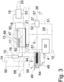
- biomass, municipal solid waste (MSW) or other suitable waste materials are delivered into hoppers 40 and 32 as received, or alternatively after being prepared by various methods such as size reduction, sort to provide more homogeneous fuel streams, or a pre-clean to separate certain undesirable materials such as metals, glass and various plastics for recycle before fuel is introduced to the primary gasification reactor and pyrolysis reactor.
- a first fuel stream enters the process and into a first thermal chamber such as primary gasification reactor 48 in an oxygen deprived condition via fuel hoppers 40 and first fuel feed system such as feeders 7, and a second fuel stream enters into a pyrolysis apparatus such as pyrolysis reactor 33 in an oxygen starved condition via fuel hopper 32 and through second fuel feed system such as feeders 4.
- a pyrolysis apparatus such as pyrolysis reactor 33 in an oxygen starved condition via fuel hopper 32 and through second fuel feed system such as feeders 4.
- Various known or commercially available systems can be utilized for feeders 7 and 4, including but not limited to ram/plunger mechanisms, augers, shaftless augers, extrusion screws, air-locks or combinations of these and other systems capable of delivering a desired amount of fuel to the primary gasification reactor 48 and to the pyrolysis reactor 33 while eliminating or reducing oxygen content in the form of air.
- Feed systems 7 and 4 are configured to restrict or eliminate the flow of oxygen into the reactors 48 and 33 while at
- First fuel stream is delivered from hopper 40 via infeed system 7 into primary gasification reactor 48.
- First fuel stream is moved progressively from entry point, or fuel inlet end, of the feed system 7 to a gasification zone of primary gasification reactor 48 and to the ash removal end and ash extraction system 36 via a suitable conveyance system, which could be a moving floor system, series of augers, shuffle floor system or any other conveyance method capable of moving first fuel stream horizontally from the inlet of gasification reactor 7 to the exit of gasification reactor 48 at the ash extraction point 36.
- the first fuel stream material absorbs thermal energy by direct contact, conduction and convection from the counterflowing hot partially oxidized dilute syn-gasses 39 being produced by a thermal oxidation reaction taking place in the primary gasification zone 9, where the thermal oxidation reaction takes place between the first fuel stream and air being injected via fan 10 and is controlled to maintain a partial thermal oxidation reaction temperature in the range of 427oC to 982oC (800°F to 1800°F) in the primary gasification zone 9.
- a first synthetic gas stream such as high temperature partially oxidized dilute syn-gasses 39 are produced in the primary gasification reactor 48 and the high temperature dilute syn-gasses 39 are caused to travel counterflow, above the incoming first fuel stream and moving toward a first gas conduit such as conduit 6, due to the negative pressure maintained on the system via a downstream ID fan 44, Dilute syn-gasses travel in a counter flow direction and above the incoming fuel to the primary gasification reactor.
- the high temperature dilute syn-gasses 39 travel via conduit 6 into a thermal catalytic reactor having a second thermal chambers such as thermal oxidizer 49 where they are blended with incoming air traveling via conduit 11 and delivered by fan 45 to conduits 3 and then into thermal oxidizer 49.
- Dilute syn-gasses and air are reacted in the thermal oxidizer 49 at a temperature range from 649oC to 1371oC (1200°F to 2500°F) controlled by the onboard programmable logic controller (PLC) system or the like that is configured to control the air/dilute syn-gas mixture ratio in order to sustain a complete thermal oxidation of the dilute syn-gasses and air mixture into high temperature fully reacted flue gasses (FG) in the thermal oxidizer 49.
- the high temperature fully reacted flue gasses (FG) move through the thermal oxidizer 49 traveling away from inlet conduit 6 toward a flue gas conduit such as exit conduit 60.
- the flue gasses travel via conduit 60 to quench/scrubber chamber 47 and upon entering chamber 47 pass through a conduit 66 having a series of liquid spray heads 13. As the flue gasses flow through conduit 66 they come into direct contact with the liquids flowing from multiple spray heads 13 and effectively transfer heat energy into the liquid flowing from spray heads 13. Liquid flowing through spray heads 13 is delivered from the reservoir in the lower part of chamber 47 via liquid pump 21. Hot liquids flow from chamber 47 via pump 21 to heat exchanger 19 where the liquids transfer thermal energy to the incoming fluids (liquids or gasses) traveling in and out of heat exchanger 19 at inlet/outlet 20.
- the fluids traveling in and out of heat exchanger 19 function as a heat extraction method to deliver thermal energy produced by the process and present in the high temperature flue gasses, to desired applications such as space heating of buildings or thermal energy for use in dryers etc.
- the now cooled liquid flows via conduit 18 to the spray heads 13 and then into reservoir at the bottom of chamber 47.
- the flue gasses transfer thermal energy into the circulated liquid, effectively raising the temperature of the circulated liquid to approximately 26.7oC to 100oC (80°F to 212°F).
- the circulated liquid then flows downward to be contained in the reservoir at the bottom of chamber 47.
- a controlled amount of saturated or super-heated vapor 50 may be produced in chamber 47 and conduit 66 from the direct contact of the fluid spray and the high temperature flue gasses.
- the now cooled mixture of flue gasses and saturated or super-heated vapor exit chamber 47 via conduit 17 traveling to condenser 16, drawn by the negative pressure maintained on the system by Induced Draft (ID) fan 44.
- ID Induced Draft
- the vapor and flue gasses are cooled in condenser 16 resulting in the phase change of the vapors to liquid form allowing for the separation of the condensed liquids from the cooled flue gasses.
- the condensed liquids exit the condenser 16 via conduit 58 or alternatively return to chamber 47 via conduit 67.
- the cooled flue gasses exit condenser 16 and travel through ID fan 44 to exit at 11.
- the cooled flue gasses may travel via conduit 68 to be drawn into the process air stream via fan 45 and travel to the thermal oxidizer 49 via air headers 3 to be re-used as an oxidizing agent or a diluent to control temperatures of the thermal oxidation reaction.
- ID fan 44 The function of ID fan 44 is to maintain the desired negative pressure on chamber 47, thermal oxidizer 49 and primary gasification chamber 48. Negative pressure is controlled by an onboard PLC which receives pressure information from sensors on both the primary gasification chamber and thermal oxidizer and based on the input from these sensors the PLC increases or decreases the speed of the ID fan 44 as needed to maintain the desired negative pressure based on an operator setpoint.
- a second fuel stream is conveyed into the pyrolysis reactor 33 using methods resulting in the second fuel stream entering the pyrolysis reactor 33 in an oxygen starved condition through second fuel feed system such as infeed system 4 from fuel storage hopper 32.
- the second fuel stream Upon entering the pyrolysis reactor 33 the second fuel stream rapidly absorbs thermal energy by conduction and convection from the gasses and radiant heat conditions present inside the primary gasification reactor zone 9 producing a rapid increase in temperature of the second fuel stream resulting in pyrolysis of the second fuel stream into primarily two components - a second synthetic gas stream such as a mixture of high temperature rich synthetic gasses (RG) which have been partially 'cracked' into shorter molecular chains 65; and a volume of solid materials made up of various solid materials such as ash, biochar, fixed carbon and non-organic residue.
- RG high temperature rich synthetic gasses
- the non-organic residue is made up of materials that do not phase change or volatize at the pyrolysis reactor temperatures. Materials such as ash, biochar, metals, glass, silica could be ingredients of the residue mixture.
- the partially cracked RG mixture 65 travels out of the pyrolysis reactor 33 via conduit 8 and into a secondary thermal chamber such as the high temperature thermal/catalytic reactor 1 and through a catalyst chamber such as the catalyst bed 2.
- the non-organic residue and fixed carbon materials produced in pyrolysis reactor 33 during the pyrolysis of the second fuel stream move/fall downward into the primary gasification reactor 48, conveyed by gravity and thereby moving out of the pyrolysis reactor 33, into the primary gasification reactor 48 and are then collected in the ash reservoir 34 and finally removed from the primary gasification reactor 48 via a conveyance system and then through airlock 59 and conduit 35.
- the RG gasses 65 are effectively drawn out of the pyrolysis reactor 33 and through the thermal catalytic reactor 1 by negative pressure maintained on the entire pyrolysis system by compressor 24.
- the negative pressure is controlled by a PLC receiving information from pressure instruments place in the pyrolysis reactor ducts as needed and the PLC adjusts the speed of the compressor drive motor on compressor 24 via a variable frequency drive to maintain the desired operator negative pressure set-point.
- the RG gasses 65 produced in pyrolysis reactor 33 may follow one or both of two paths: 1) In response to the negative pressure maintained by compressor 24, the RG gasses may travel out of the pyrolysis reactor 33 via conduit 8 into the thermal/catalytic reactor 1 where the RG gasses remain separated from the high temperature flue gasses present in the thermal oxidizer 49; and/or 2) in response to competing negative pressures maintained in the primary gasification rector 48, by ID fan 44 the RG gasses may move away from the pyrolysis reactor 33 and into the primary gasification reactor 48 where the RG gasses may mix with the dilute syn-gasses present and being produced in the primary reaction area 9 and may undergo partial or complete thermal oxidation in the primary gasification reaction area 9, or, the RG gasses may mix with dilute syn-gas 39 resident in the primary gasification reactor 48 which are continuously moving counterflow and above the fuel bed to exit the primary gasification reactor 48 via conduit 6 and thereby moving into thermal oxidizer 49.
- thermal/catalytic reactor 1 Upon entering thermal/catalytic reactor 1 the partially cracked RG gasses undergo a further increase in temperature absorbing thermal energy indirectly by conduction of thermal energy through the walls of the thermal/catalytic reactor apparatus 1, from the high temperature flue gasses and radiant heat energy resident inside the thermal oxidizer 49.
- the high temperature complete oxidation reaction taking place in thermal oxidizer 49 is sustained by the oxidation of dilute syn-gas from the primary gasification reactor 48 combined with air being directed into thermal oxidizer 49 via conduits 3 and delivered by process air fan 45 resulting in the complete oxidation of the dilute syn-gasses into high temperature flue gas (FG) 39.
- the RG gasses remain separate from the flue gasses resident in the thermal oxidizer 49 and absorbs thermal energy indirectly via conduction through the walls/surface area of the thermal/catalytic reactor 1. As the temperatures of the RD gasses increase further additional cracking/degradation of the molecules making up the RD gasses take place, further reducing the gasses into shorter carbon (C) chain molecular compounds.
- the RD gasses then pass through the catalyst bed resident in the catalytic reactor 2 resulting in a further reduction of the molecular structure of the RD gasses forming a synthetic fuel gas with carbon chains of ⁇ C4-C60 suitable as a fuel gas feed stock (FG) or alternatively the RD gasses pass through a selective catalyst bed resident in the catalytic reactor 2 resulting in a reforming of the hydrocarbon chains selectively based on the action of the catalyst employed which produces a targeted group of hydrocarbon chains that when cooled and condensed, form a liquid product such as Naptha (C6-C13) that could be suitable for use as a feedstock for new plastic production in the place of Natural Gas, as well as other desired hydrocarbon mixtures and carbon chain lengths useful for other purposes.
- FG fuel gas feed stock
- the high temperature processed gas RG travels through to recuperator 27 where the high temperature processed gas, RG exchanges thermal energy with incoming air stream via indirect exchange in recuperator 27.
- Process air fan 10 pulls air through the recuperator 27 via inlet 52, through recuperator 27, through conduit 51 and through process air fan 10 which delivers the now pre-heated air to the primary gasification reaction area 9 via conduit 63 which can be used as a thermal oxidizing agent in the primary gasification chamber 9.
- scrubbing medium may be any number of fluids such as water, oils/waxes/paraffins/hydrocarbons mixtures and/or a mixture of various condensable liquids as they are removed from the now Renewable Natural Gas (RNG) flow and collect in reservoir 31.
- RNG now Renewable Natural Gas
- the SM comes into direct contact with the incoming RG and effectively cools the RG to ⁇ 149°C ( ⁇ 300°F) or to a desired temperature adequate to reduce the RG temperatures to a level where hydrocarbon chains greater than C5 experience phase change from vapor phase back to liquid phase at room temperatures allowing them to be absorbed by the circulating SM fluid flow and removed from the RG flow.
- the now heated and rich or loaded SM travels downward in quench/scrubbing chamber 29 traveling through cooler 30 and then into reservoir 31.
- Cooler 30 functions to cool the SM to a suitable temperature but maintaining the SM at a high enough temperature to stay in liquid form avoiding solids formation of any waxes or long chain hydrocarbons or tars etc.
- SM is removed from reservoir 31 via pump 46 and travels via conduit 43 to exit the system via conduit 37 for other use (i.e. in the case of Naphtha, as feedstock for new plastic production), or, alternatively the collected/excess SM can travel via conduit 38 to be injected into primary gasification reactor 48 for use as addition fuel for the primary gasification reaction effectively recirculating the liquids through the entire process.
- RNG Renewable Natural Gas
- the now cooled and cleaned processed gasses or Renewable Natural Gas (RNG) travels from quench/scrubber 29 to pre-cooler 25 and then through compressor 24 and into storage reservoir 41 where they are stored at a suitable pressure for further use.
- the pressurized RNG is delivered to a beneficial application such as a synthetic gas fueled engine 42 which could be either rotary, reciprocating or other, capable of driving various machines such as a generator 22 suitable for producing electricity.
- intake air preheat can be employed by drawing outside air in via conduit 55 and through pre-cooler 25 and into engine 42 and diluted by air coming via inlet 54 as needed to control air inlet temperatures to the engine in use.
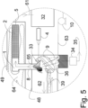
- FIG. 6 there is shown a detailed view of an alternate embodiment showing a third fuel infeed system allowing for two different fuels to be fed into the primary chamber in an oxygen deprived condition and a single fuel blend being fed into the pyrolysis reactor under oxygen starved conditions.
- a second or third feeder could be configured to feed into the pyrolysis reactor under oxygen starved conditions.
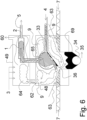
- FIG. 7 there is shown a detailed view an alternate embodiment showing a variation to FIG. 6 where all three reactors are employed - Thermal Oxidizer, Primary Gasification Chamber, Pyrolysis Reactor. Also, this embodiment is being fueled by a single blended fuel coming into Pyrolysis Reactor 33 under oxygen starved conditions via infeed system 4.
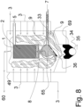
- FIG. 8 there is shown a detailed view of an alternate embodiment where the thermal oxidizer and primary reactor are combined into a single vertical configuration and are fed by a single blended fuel (SBF) to be processed in pyrolysis reactor 33.
- SBF blended fuel
- an adequate amount of fuel is fed into Pyrolysis reactor 33 via inlet 7 (or additional inlets) whereby an excess of rich syn-gas RG is produced within reactor 33 than is being drawn off and out via conduit 5.
- the slight imbalance in pressure between the primary reactor 49 and conduit 8 produces a flow preference for the RG to move out of reactor 33 and into primary reaction area 9 as opposed to dilute-syn-gas and partially reacted syn-gas traveling from primary reaction area 9 and into pyrolysis reactor 33, effectively providing a gaseous seal or separation between the two qualities and species of gasses.
- the deliberate ⁇ leakage' from pyrolysis reactor 33 of RG into primary reaction area 9 effectively maintains a separation between the dilute syn-gasses and products of oxidation from the primary reactor 9 and the RG allowing only RG to travel via conduit 5 for further processing as either a Renewable Natural Gas /fuel gas or into a valuable liquid form suitable to be used for the manufacture of other products such as new plastics.
- the system would be operated in such a way as to feed the needed amount of fuel or SBF to produce an adequate amount of RG to both meet the thermal energy requirements in the primary gasifier 49 needed to maintain the desired temperature profile as well as to deliver an adequate or desired volume of RG to conduit 5 for further processing.
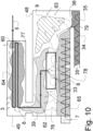
- FIG. 9 there is shown a detailed view of an alternate embodiment where the pyrolysis reactor 33 is fitted with an adjustable hot-plate wall 72 and is hinged allowing angle adjustment to made to optimize the collection of fixed carbon and contaminants 70 that collect on hot-plate 72 by rotating hot-plate 72 on hinge 71.
- a vibratory rod 73 attached to hot-plate 72 may be used to aid in removing the carbon and contaminates 70 from hot-plate 72.
- Vibratory rod 73 could be any of several commercially available vibrating machines such as those sold by Vibco. (http://www.vibco.com).
- FIG. 10 there is shown a detailed view of the Pyrolysis Reactor employing an alternate method of collecting Rich Syn-Gas via a Pyrolysis Reactor Hood and Processing a single Blended Fuel Stream (SBF).
- FIG. 10 details an alternate embodiment where a pyrolysis reactor hood 78 is suspended above the counterflow horizontally moving fuel bed where rich synthetic gasses (RG) are collected in pyrolysis reactor hood 78.
- Blended fuel stream (SBF) enters the process via fuel feeder 7 under oxygen deprived/reduced conditions and is conveyed horizontally through Primary gasification reactor 48 from fuel feeder 7 to ash extraction point 36.
- SBF moves in a horizontal and counterflow direction to the dilute syn-gasses 39, traveling from fuel feeder 7 to extraction point 36 and is progressively heated by absorbing thermal energy for the high temperature counterflowing dilute syn-gasses 39 which are produced in primary gasification zone 9.
- the SBF material increases in temperature causing water and light hydrocarbon compounds /VOC's to be driven off in the drying section of the primary gasifier 76.
- the SBF material continues to absorb thermal energy from the counterflowing dilute syn-gasses 39 which are traveling counterflow and above the fuel bed, the SBF begins to phase change /volatize, releasing rich syn-gasses(undiluted gasses not containing products of thermal oxidation such as CO2 or nitrogen present in air used as oxidizing agent in gasification)within Pyrolysis Hood 78.
- SBF material continues to move counterflow and horizontally from fuel inlet 7 to ash outlet 36 and once past the Pyrolysis Hood 78, enters the final reaction zone 79 where, as the material reaches maximum process temps, the remaining syn-gasses are released into primary reaction zone 9.
- a controlled amount of air used as an oxidant is injected into primary reaction zone 9 via conduits 63 from fan 10 sustaining an thermal oxidation reaction between the syn-gasses and the oxygen present in the air in order to maintain an Operator temperature setpoint in primary reaction zone 9.
- the system controls the amount of air delivered into primary reaction area 9 via an onboard PLC to maintain an operator temperature set-point by monitoring temperature information received from various temperature probes placed in the Primary gasification chamber 48, and then actuating commercially available inline valves which control the flow of air coming from Primary Air Fan 10.
- Rich Syn-Gasses (RG) collected in Pyrolysis Reactor Hood 78 are drawn through conduit 8 and continue through a thermal cracker/heat exchanger 78 where the RG temperatures may be increased to temperatures in the range of 816oC to 1371oC (1500°F to 2500°F) causing further thermal cracking of the RG into shorter length hydrocarbon chains.
- the Cracked RG then continues via conduit 5 for further process or for use as a fuel gas or Renewable Natural Gas (RNG) in systems such as electrical generating equipment.
- RNG Renewable Natural Gas
Landscapes
- Chemical & Material Sciences (AREA)
- Engineering & Computer Science (AREA)
- Oil, Petroleum & Natural Gas (AREA)
- Combustion & Propulsion (AREA)
- Organic Chemistry (AREA)
- Chemical Kinetics & Catalysis (AREA)
- General Chemical & Material Sciences (AREA)
- Materials Engineering (AREA)
- Processing Of Solid Wastes (AREA)
Claims (13)
- Système pour la production de gaz de synthèse à partir de combustible solide comprenant des déchets, des déchets solides urbains ou de la biomasse et pour la valorisation du gaz de synthèse produit, le système comprenant :une première chambre thermique (48) ayant une zone de gazéification (9) dans laquelle un premier flux de combustible arrivant est gazéifié par oxydation thermique pour produire un premier flux de gaz de synthèse (39) et de la chaleur ;un premier système d'alimentation en combustible (7) qui apporte le premier flux de combustible à la zone de gazéification d'une manière privée d'oxygène résultant en un apport privé d'oxygène du premier flux de combustible à la première chambre thermique (48) ;un réacteur de pyrolyse (33) logé à l'intérieur de la première chambre thermique (48) ;un second système d'alimentation en combustible (4) qui apporte un second flux de combustible au réacteur de pyrolyse (33) d'une manière qui empêche de l'oxygène de pénétrer dans le réacteur de pyrolyse (33), la chaleur produite dans la zone de gazéification étant transmise au second flux de combustible dans le réacteur de pyrolyse (33) pour provoquer la pyrolyse du second flux de combustible et produire un second flux de gaz de synthèse ; etun réacteur thermique catalytique comprenant une seconde chambre thermique (49) et une chambre de catalyseur (2) délimitée par un logement situé à l'intérieur de la seconde chambre thermique (49), la chambre de catalyseur (2) contenant un catalyseur sélectionné, la seconde chambre thermique (49) pouvant fonctionner pour recevoir le premier flux de gaz de synthèse et oxyder thermiquement complètement le premier flux de gaz de synthèse pour produire du gaz effluent à haute température qui transmet de la chaleur au logement de la chambre de catalyseur (2) et la chambre de catalyseur (2) pouvant fonctionner pour recevoir le second flux de gaz de synthèse et pour craquer thermiquement le second flux de gaz de synthèse pour produire un flux de gaz de synthèse craqué, puis pour envoyer le flux de gaz de synthèse craqué au catalyseur pour donner un produit gazeux ou liquide fini ayant une composition chimique souhaitée telle que déterminée par le catalyseur sélectionné présent dans la chambre de catalyseur (2).
- Système pour la production de gaz de synthèse à partir de combustible solide comprenant des déchets, des déchets solides urbains ou de la biomasse et pour la valorisation du gaz de synthèse produit, le système comprenant :une première chambre thermique (48) ayant une zone de gazéification dans laquelle du combustible est gazéifié par oxydation thermique pour produire un premier flux de gaz de synthèse et de la chaleur ;un réacteur de pyrolyse (33) logé à l'intérieur de la première chambre thermique (48) ;un système d'alimentation en combustible qui apporte un flux de combustible au réacteur de pyrolyse (33) et à la zone de gazéification d'une manière qui empêche de l'oxygène de pénétrer dans le réacteur de pyrolyse (33), la chaleur produite dans la zone de gazéification étant transmise au flux de combustible dans le réacteur de pyrolyse (33) pour provoquer la pyrolyse du flux de combustible et produire un second flux de gaz de synthèse ; etun réacteur thermique catalytique comprenant une seconde chambre thermique (49) et une chambre de catalyseur (2) délimitée par un logement situé à l'intérieur de la seconde chambre thermique (49), la chambre de catalyseur (2) contenant un catalyseur sélectionné, la seconde chambre thermique (49) pouvant fonctionner pour recevoir le premier flux de gaz de synthèse et oxyder thermiquement complètement le premier flux de gaz de synthèse pour produire du gaz effluent à haute température qui transmet de la chaleur au logement de la chambre de catalyseur (2) et la chambre de catalyseur (2) pouvant fonctionner pour recevoir le second flux de gaz de synthèse et pour craquer thermiquement le second flux de gaz de synthèse pour produire un flux de gaz de synthèse craqué, puis pour envoyer le flux de gaz de synthèse craqué au catalyseur pour donner un produit gazeux ou liquide fini ayant une composition chimique souhaitée telle que déterminée par le catalyseur sélectionné présent dans la chambre de catalyseur (2).
- Système selon l'une quelconque des revendications 1 à 2, le réacteur thermique catalytique étant séparé de la première chambre thermique (48) et le système comprenant en outre une première conduite de gaz (6) allant de la zone de gazéification à la seconde chambre thermique (49) et une seconde conduite de gaz (8) allant du réacteur de pyrolyse (33) à la chambre de catalyseur (2).
- Système selon l'une quelconque des revendications 1 à 3, la seconde chambre thermique (49) comportant une sortie de gaz effluent et une soufflante en aval de la sortie de gaz effluent qui produit une pression négative en amont d'elle-même pour aspirer le premier flux de gaz de synthèse hors de la première chambre thermique (48), par la première conduite de gaz (6), et dans la seconde chambre thermique (49) et le gaz effluent à haute température après le réacteur catalytique.
- Système selon l'une quelconque des revendications 1 à 4, la première chambre thermique (48) ayant une extrémité d'entrée de combustible et une extrémité de sortie de cendres et un transporteur pour déplacer le premier flux de combustible de l'extrémité d'entrée de combustible vers l'extrémité de sortie de cendres de sorte qu'une grande partie du premier flux de gaz de synthèse est produite vers l'extrémité de sortie de cendres.
- Système selon la revendication 5, le réacteur de pyrolyse (33) étant à côté de l'extrémité de sortie de cendres (36).
- Système selon la revendication 6, la première conduite de gaz (6) partant de la première chambre thermique (48) à côté de l'extrémité d'entrée de combustible pour favoriser une circulation du premier flux de gaz de synthèse qui est à contre-courant du déplacement du premier flux de combustible dans la première chambre thermique (48).
- Système selon l'une quelconque des revendications 5 à 7 comprenant en outre un mécanisme d'extraction de cendres qui retire les cendres et les résidus de la première chambre thermique (48) par le biais de la sortie de cendres (36).
- Système selon l'une quelconque des revendications 1 à 8 comprenant en outre une conduite de gaz effluent (60) pour transporter le gaz effluent du réacteur thermique catalytique à un système pour l'utilisation d'une partie de la chaleur restante du gaz effluent pour des applications de chauffage utiles.
- Système selon l'une quelconque des revendications 1 à 8 comprenant en outre une surface chauffante dans le réacteur de pyrolyse (33) et le second système d'alimentation en combustible (4) pouvant fonctionner pour transporter le second flux de combustible sur la surface chauffante (72), la surface chauffante étant chauffée suite à l'oxydation thermique ayant lieu dans la zone de gazéification à une température suffisante pour commencer la pyrolyse du second flux de combustible lors du contact avec la surface chauffante.
- Système selon la revendication 10, la surface chauffante comprenant un élément de type plaque (72) incliné vers le bas à partir d'une extrémité de réception de combustible et qui est en communication thermique avec la zone de gazéification de la première chambre thermique (48) pour recevoir de la chaleur produite à partir de l'oxydation thermique du premier flux de combustible.
- Système selon la revendication 11 où l'élément de type plaque (72) est articulé (71) au niveau de son extrémité de réception de combustible de telle sorte que l'élément de type plaque (72) peut être déplacé dans une orientation verticale pour l'élimination de toute cendre et tout résidu accumulés de la surface chauffante.
- Système selon la revendication 12 comprenant en outre un actionneur (73) pour déplacer l'élément de type plaque (72) entre une orientation inclinée et une orientation verticale.
Applications Claiming Priority (2)
| Application Number | Priority Date | Filing Date | Title |
|---|---|---|---|
| US201962797897P | 2019-01-28 | 2019-01-28 | |
| PCT/CA2020/050099 WO2020154801A1 (fr) | 2019-01-28 | 2020-01-28 | Système et procédés d'amélioration de gaz synthétique produit à partir de déchets, de déchets solides municipaux ou de biomasse |
Publications (3)
| Publication Number | Publication Date |
|---|---|
| EP3918031A1 EP3918031A1 (fr) | 2021-12-08 |
| EP3918031A4 EP3918031A4 (fr) | 2022-11-02 |
| EP3918031B1 true EP3918031B1 (fr) | 2024-09-04 |
Family
ID=71839846
Family Applications (1)
| Application Number | Title | Priority Date | Filing Date |
|---|---|---|---|
| EP20749183.8A Active EP3918031B1 (fr) | 2019-01-28 | 2020-01-28 | Système d'amélioration de gaz synthétique produit à partir de déchets, de déchets solides municipaux ou de biomasse |
Country Status (5)
| Country | Link |
|---|---|
| US (1) | US11959037B2 (fr) |
| EP (1) | EP3918031B1 (fr) |
| AU (1) | AU2020213638A1 (fr) |
| CA (1) | CA3127879A1 (fr) |
| WO (1) | WO2020154801A1 (fr) |
Families Citing this family (3)
| Publication number | Priority date | Publication date | Assignee | Title |
|---|---|---|---|---|
| AU2020331697A1 (en) * | 2019-08-21 | 2022-03-10 | Ags Energy (Ireland) Limited | A gasification apparatus and method |
| CN113072967A (zh) * | 2021-05-07 | 2021-07-06 | 哈尔滨职业技术学院 | 一种燃煤耦合生物质热解的多联产工艺 |
| EP4141299A1 (fr) | 2021-08-27 | 2023-03-01 | Norham | Clapet anti-retour à membrane |
Family Cites Families (7)
| Publication number | Priority date | Publication date | Assignee | Title |
|---|---|---|---|---|
| DE19930071C2 (de) * | 1999-06-30 | 2001-09-27 | Wolfgang Krumm | Verfahren und Vorrichtung zur Pyrolyse und Vergasung von organischen Stoffen und Stoffgemischen |
| DE10047787A1 (de) | 2000-09-20 | 2002-03-28 | Ver Energiewerke Ag | Verfahren zur Brenngaserzeugung aus Hausmüll und ähnlichen Abfällen durch Pyrolyse mit nachgeschalteter Umwandlung der Pyrolyseprodukte Schwelgas und Schwelkoks in Permanentgas |
| CN101139532B (zh) * | 2006-09-08 | 2010-12-29 | 中国科学院过程工程研究所 | 固体燃料解耦流化床气化方法及气化装置 |
| US9017428B2 (en) * | 2010-11-16 | 2015-04-28 | Kior, Inc. | Two-stage reactor and process for conversion of solid biomass material |
| US8568493B2 (en) * | 2011-07-25 | 2013-10-29 | Cool Planet Energy Systems, Inc. | Method for producing negative carbon fuel |
| US20150129806A1 (en) * | 2013-11-08 | 2015-05-14 | Ammonia Casale Sa | Process for Producing Ammonia Synthesis Gas and a Method for Revamping a Front-End of an Ammonia Plant |
| WO2018089520A1 (fr) * | 2016-11-09 | 2018-05-17 | Phillips 66 Company | Valorisation/hydrostabilisation fluidisée de vapeurs de pyrolyse |
-
2020
- 2020-01-28 WO PCT/CA2020/050099 patent/WO2020154801A1/fr unknown
- 2020-01-28 US US17/426,595 patent/US11959037B2/en active Active
- 2020-01-28 AU AU2020213638A patent/AU2020213638A1/en active Pending
- 2020-01-28 CA CA3127879A patent/CA3127879A1/fr active Pending
- 2020-01-28 EP EP20749183.8A patent/EP3918031B1/fr active Active
Also Published As
| Publication number | Publication date |
|---|---|
| EP3918031A1 (fr) | 2021-12-08 |
| US20220089961A1 (en) | 2022-03-24 |
| EP3918031A4 (fr) | 2022-11-02 |
| CA3127879A1 (fr) | 2020-08-06 |
| AU2020213638A1 (en) | 2021-08-19 |
| WO2020154801A1 (fr) | 2020-08-06 |
| US11959037B2 (en) | 2024-04-16 |
Similar Documents
| Publication | Publication Date | Title |
|---|---|---|
| Campuzano et al. | Auger reactors for pyrolysis of biomass and wastes | |
| EP3918031B1 (fr) | Système d'amélioration de gaz synthétique produit à partir de déchets, de déchets solides municipaux ou de biomasse | |
| AU2002220288B2 (en) | Process and gas generator for generating fuel gas | |
| US9631153B2 (en) | Adaptable universal method for producing synthetic products | |
| US11248184B2 (en) | Gasification system | |
| EP2694624B1 (fr) | Processus de fonctionnement de procédé de production de gaz de synthèse à partir de matière carbonée | |
| RU2393200C2 (ru) | Способ термической переработки твердых органических отходов и установка для его осуществления | |
| CN102341485A (zh) | 用于生物质的热化学转化的方法和系统 | |
| WO2009093107A1 (fr) | Réacteur agitateur pyrolytique de gazéification à contre-courant | |
| RU2470863C2 (ru) | Способ и устройство для получения среднего дистиллята из углеводородсодержащих энергоносителей | |
| CN113195685A (zh) | 处理含碳材料的工艺和用于其的设备 | |
| AU2014366887B2 (en) | Apparatus for pyrolysing carbonaceous material | |
| Kaur et al. | Commercial or pilot-scale pyrolysis units for conversion of biomass to bio-oils: state of the art | |
| RU2725434C1 (ru) | Способ термической деструкции сыпучей органики в вертикальном реакторе газификации | |
| KR20190001856U (ko) | 바이오매스 가스화장치 및 이를 갖는 바이오매스 처리설비 | |
| US20130118075A1 (en) | System And Method For Thermal Conversion Of Carbon Based Materials | |
| EP4151706A1 (fr) | Procédé et dispositif de fabrication d'un produit de gaz à faible teneur en goudron et en poussières | |
| EP1945741B1 (fr) | Procede et dispositif pour obtenir de l'energie a partir de supports bioenergetiques et d'autres matieres organiques | |
| RU2785096C1 (ru) | Газогенераторная установка и способ генерации газа для производства водородсодержащего синтез-газа | |
| CZ303367B6 (cs) | Zpusob zplynování upravené biomasy a zarízení k jeho provádení |
Legal Events
| Date | Code | Title | Description |
|---|---|---|---|
| STAA | Information on the status of an ep patent application or granted ep patent |
Free format text: STATUS: THE INTERNATIONAL PUBLICATION HAS BEEN MADE |
|
| PUAI | Public reference made under article 153(3) epc to a published international application that has entered the european phase |
Free format text: ORIGINAL CODE: 0009012 |
|
| STAA | Information on the status of an ep patent application or granted ep patent |
Free format text: STATUS: REQUEST FOR EXAMINATION WAS MADE |
|
| 17P | Request for examination filed |
Effective date: 20210806 |
|
| AK | Designated contracting states |
Kind code of ref document: A1 Designated state(s): AL AT BE BG CH CY CZ DE DK EE ES FI FR GB GR HR HU IE IS IT LI LT LU LV MC MK MT NL NO PL PT RO RS SE SI SK SM TR |
|
| DAV | Request for validation of the european patent (deleted) | ||
| DAX | Request for extension of the european patent (deleted) | ||
| A4 | Supplementary search report drawn up and despatched |
Effective date: 20221005 |
|
| RIC1 | Information provided on ipc code assigned before grant |
Ipc: C10K 3/02 20060101ALI20220929BHEP Ipc: C10L 3/00 20060101ALI20220929BHEP Ipc: C10B 57/02 20060101AFI20220929BHEP |
|
| GRAP | Despatch of communication of intention to grant a patent |
Free format text: ORIGINAL CODE: EPIDOSNIGR1 |
|
| STAA | Information on the status of an ep patent application or granted ep patent |
Free format text: STATUS: GRANT OF PATENT IS INTENDED |
|
| INTG | Intention to grant announced |
Effective date: 20240201 |
|
| GRAJ | Information related to disapproval of communication of intention to grant by the applicant or resumption of examination proceedings by the epo deleted |
Free format text: ORIGINAL CODE: EPIDOSDIGR1 |
|
| STAA | Information on the status of an ep patent application or granted ep patent |
Free format text: STATUS: REQUEST FOR EXAMINATION WAS MADE |
|
| GRAP | Despatch of communication of intention to grant a patent |
Free format text: ORIGINAL CODE: EPIDOSNIGR1 |
|
| STAA | Information on the status of an ep patent application or granted ep patent |
Free format text: STATUS: GRANT OF PATENT IS INTENDED |
|
| INTC | Intention to grant announced (deleted) | ||
| GRAJ | Information related to disapproval of communication of intention to grant by the applicant or resumption of examination proceedings by the epo deleted |
Free format text: ORIGINAL CODE: EPIDOSDIGR1 |
|
| STAA | Information on the status of an ep patent application or granted ep patent |
Free format text: STATUS: REQUEST FOR EXAMINATION WAS MADE |
|
| GRAP | Despatch of communication of intention to grant a patent |
Free format text: ORIGINAL CODE: EPIDOSNIGR1 |
|
| STAA | Information on the status of an ep patent application or granted ep patent |
Free format text: STATUS: GRANT OF PATENT IS INTENDED |
|
| GRAS | Grant fee paid |
Free format text: ORIGINAL CODE: EPIDOSNIGR3 |
|
| INTG | Intention to grant announced |
Effective date: 20240626 |
|
| GRAA | (expected) grant |
Free format text: ORIGINAL CODE: 0009210 |
|
| STAA | Information on the status of an ep patent application or granted ep patent |
Free format text: STATUS: THE PATENT HAS BEEN GRANTED |
|
| INTC | Intention to grant announced (deleted) | ||
| INTG | Intention to grant announced |
Effective date: 20240723 |
|
| RAP3 | Party data changed (applicant data changed or rights of an application transferred) |
Owner name: IQ ENERGY INC. |
|
| AK | Designated contracting states |
Kind code of ref document: B1 Designated state(s): AL AT BE BG CH CY CZ DE DK EE ES FI FR GB GR HR HU IE IS IT LI LT LU LV MC MK MT NL NO PL PT RO RS SE SI SK SM TR |
|
| REG | Reference to a national code |
Ref country code: GB Ref legal event code: FG4D |
|
| REG | Reference to a national code |
Ref country code: CH Ref legal event code: EP |