EP3917853B1 - Dispensing bottle, closure cap, and method for manufacture - Google Patents
Dispensing bottle, closure cap, and method for manufacture Download PDFInfo
- Publication number
- EP3917853B1 EP3917853B1 EP20866805.3A EP20866805A EP3917853B1 EP 3917853 B1 EP3917853 B1 EP 3917853B1 EP 20866805 A EP20866805 A EP 20866805A EP 3917853 B1 EP3917853 B1 EP 3917853B1
- Authority
- EP
- European Patent Office
- Prior art keywords
- disk
- base
- ridge
- angled tip
- fluid
- Prior art date
- Legal status (The legal status is an assumption and is not a legal conclusion. Google has not performed a legal analysis and makes no representation as to the accuracy of the status listed.)
- Active
Links
Images











Classifications
-
- B—PERFORMING OPERATIONS; TRANSPORTING
- B65—CONVEYING; PACKING; STORING; HANDLING THIN OR FILAMENTARY MATERIAL
- B65D—CONTAINERS FOR STORAGE OR TRANSPORT OF ARTICLES OR MATERIALS, e.g. BAGS, BARRELS, BOTTLES, BOXES, CANS, CARTONS, CRATES, DRUMS, JARS, TANKS, HOPPERS, FORWARDING CONTAINERS; ACCESSORIES, CLOSURES, OR FITTINGS THEREFOR; PACKAGING ELEMENTS; PACKAGES
- B65D47/00—Closures with filling and discharging, or with discharging, devices
- B65D47/04—Closures with discharging devices other than pumps
- B65D47/06—Closures with discharging devices other than pumps with pouring spouts or tubes; with discharge nozzles or passages
- B65D47/08—Closures with discharging devices other than pumps with pouring spouts or tubes; with discharge nozzles or passages having articulated or hinged closures
- B65D47/0804—Closures with discharging devices other than pumps with pouring spouts or tubes; with discharge nozzles or passages having articulated or hinged closures integrally formed with the base element provided with the spout or discharge passage
-
- B—PERFORMING OPERATIONS; TRANSPORTING
- B65—CONVEYING; PACKING; STORING; HANDLING THIN OR FILAMENTARY MATERIAL
- B65D—CONTAINERS FOR STORAGE OR TRANSPORT OF ARTICLES OR MATERIALS, e.g. BAGS, BARRELS, BOTTLES, BOXES, CANS, CARTONS, CRATES, DRUMS, JARS, TANKS, HOPPERS, FORWARDING CONTAINERS; ACCESSORIES, CLOSURES, OR FITTINGS THEREFOR; PACKAGING ELEMENTS; PACKAGES
- B65D47/00—Closures with filling and discharging, or with discharging, devices
- B65D47/04—Closures with discharging devices other than pumps
- B65D47/043—Closures with discharging devices other than pumps with pouring baffles, e.g. for controlling the flow
-
- B—PERFORMING OPERATIONS; TRANSPORTING
- B65—CONVEYING; PACKING; STORING; HANDLING THIN OR FILAMENTARY MATERIAL
- B65D—CONTAINERS FOR STORAGE OR TRANSPORT OF ARTICLES OR MATERIALS, e.g. BAGS, BARRELS, BOTTLES, BOXES, CANS, CARTONS, CRATES, DRUMS, JARS, TANKS, HOPPERS, FORWARDING CONTAINERS; ACCESSORIES, CLOSURES, OR FITTINGS THEREFOR; PACKAGING ELEMENTS; PACKAGES
- B65D47/00—Closures with filling and discharging, or with discharging, devices
- B65D47/04—Closures with discharging devices other than pumps
- B65D47/20—Closures with discharging devices other than pumps comprising hand-operated members for controlling discharge
- B65D47/2018—Closures with discharging devices other than pumps comprising hand-operated members for controlling discharge comprising a valve or like element which is opened or closed by deformation of the container or closure
- B65D47/2056—Closures with discharging devices other than pumps comprising hand-operated members for controlling discharge comprising a valve or like element which is opened or closed by deformation of the container or closure lift valve type
- B65D47/2081—Closures with discharging devices other than pumps comprising hand-operated members for controlling discharge comprising a valve or like element which is opened or closed by deformation of the container or closure lift valve type in which the deformation raises or lowers the valve port
-
- B—PERFORMING OPERATIONS; TRANSPORTING
- B65—CONVEYING; PACKING; STORING; HANDLING THIN OR FILAMENTARY MATERIAL
- B65D—CONTAINERS FOR STORAGE OR TRANSPORT OF ARTICLES OR MATERIALS, e.g. BAGS, BARRELS, BOTTLES, BOXES, CANS, CARTONS, CRATES, DRUMS, JARS, TANKS, HOPPERS, FORWARDING CONTAINERS; ACCESSORIES, CLOSURES, OR FITTINGS THEREFOR; PACKAGING ELEMENTS; PACKAGES
- B65D47/00—Closures with filling and discharging, or with discharging, devices
- B65D47/04—Closures with discharging devices other than pumps
- B65D47/32—Closures with discharging devices other than pumps with means for venting
-
- B—PERFORMING OPERATIONS; TRANSPORTING
- B65—CONVEYING; PACKING; STORING; HANDLING THIN OR FILAMENTARY MATERIAL
- B65D—CONTAINERS FOR STORAGE OR TRANSPORT OF ARTICLES OR MATERIALS, e.g. BAGS, BARRELS, BOTTLES, BOXES, CANS, CARTONS, CRATES, DRUMS, JARS, TANKS, HOPPERS, FORWARDING CONTAINERS; ACCESSORIES, CLOSURES, OR FITTINGS THEREFOR; PACKAGING ELEMENTS; PACKAGES
- B65D85/00—Containers, packaging elements or packages, specially adapted for particular articles or materials
- B65D85/70—Containers, packaging elements or packages, specially adapted for particular articles or materials for materials not otherwise provided for
- B65D85/72—Containers, packaging elements or packages, specially adapted for particular articles or materials for materials not otherwise provided for for edible or potable liquids, semiliquids, or plastic or pasty materials
Definitions
- membrane valves and other similar solutions do not always sufficiently address product separation that often occurs in fluids, such as when serum, water or another thin liquid component of relatively low viscosity separates from the remainder of a fluid such as ketchup. This separation can increase leakage, increase splatter, and cause the thin liquid component to be dispensed separately from the remainder of the product.
- FIG. 3 when the flip-top lid 22 is in the open configuration, a projection 90 of the flip-top lid 22 is moved from obstructing or blocking an opening 34 in the base 20 to a position away therefrom such that the opening 34 is unobstructed.
- FIG. 3 also illustrates a central portion 30, which may be dome-shaped, through which the opening 34 extends, and a planar portion 62 disposed at least partially therearound.
- the lower surface 74 of the mouth-shaped indentation 70 as shown in the illustrative example of FIG. 3 , extends between sections of the planar portion 62.
- the mixing chamber 56 and the openings formed in the disk 42 by the disk 42 and the internal shaft 36 permit accurate dispensing and dosing of the fluid 5 within the container. Accordingly, the geometry of the disk 42 helps facilitate the proper dispensing of the fluid 5.
- the internal shaft 36 may help support the disk 42 when the disk is attached to the base 20.
- the internal or interior wall 78 of the internal shaft 36 funnels fluid 5 toward the opening 34.
- the interior wall 78 forms at least one of a circular shape or a parabolic shape.
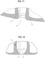
- FIG. 11 illustrates one example shape of an interior wall 78 that narrows slightly near the exit of the internal shaft 36.
- the shaft 36 may flare open again adjacent the opening 34. By flaring a bit where the opening meets the upper surface of the base, the opening permits the projection 90 to more easily and quickly be placed in the opening 34 when closing the flip-top cap 18. In yet another configuration, shown in FIG.
Landscapes
- Engineering & Computer Science (AREA)
- Mechanical Engineering (AREA)
- Closures For Containers (AREA)
Description
- This disclosure relates generally to containers for fluids. More particularly, this disclosure generally relates to containers with closure caps.
- Fluid containers occasionally have issues with dosing and leakage, especially during shipping and/or when the containers are placed in certain configurations. Many consumer products delivered in bottles may suffer from such drawbacks. By way of example, thixotropic fluids, such as, for example, ketchup or certain liquid soaps, are sometimes sold in bottles that use a flexible plastic membrane valve with an "X" shaped slit. These are sometimes used with inverted bottles that rest on their caps when not in use so that gravity retains the product in position adjacent the valve.
- One problem with this type of valve is that in some cases, product may leak through the valve when the bottle is not in use. Another problem is that during dispensing, product may squirt from the opening at an undesirably high velocity, increasing the risk of splatter. The high velocity of the product being discharged also makes proper dosing difficult because there is generally insufficient control over the product at high velocities. A third problem is that the valve may resist or prevent inflow of air to maintain interior volume after dispensing, leading to development of subatmospheric pressure, i.e., a partial vacuum, in the bottle. This can lead to paneling, i.e., buckling, or other undesirable inward deflection of container walls, which can be esthetically problematic and also functionally problematic, as it may increase the manual pressure required to dispense product, and may lead to uneven or inconsistent dispensing in response to a squeeze, i.e., manual application of pressure to the container exterior.
- Another issue is that such membrane valves are often formed of silicon, whereas other portions of the caps are often formed of another material such as polypropylene. Having a closure cap comprised of multiple materials increases the complexity and cost of manufacturing and can make recycling difficult and/or impractical, thereby making the solution less attractive for large scale use.
- Further, such membrane valves and other similar solutions do not always sufficiently address product separation that often occurs in fluids, such as when serum, water or another thin liquid component of relatively low viscosity separates from the remainder of a fluid such as ketchup. This separation can increase leakage, increase splatter, and cause the thin liquid component to be dispensed separately from the remainder of the product.
-
WO2009/046553 describes, according to its abstract, a plastic closure with a lid having an annular retaining bead in the bottom part and a disk having a support surface that is held positively or non-positively in said bead, where the disk comprises one or more through-passages, which open into a chamber. A thixotropic fluid present in a flexible container reaches the chamber through the through-passages, whereupon the fluid performs a directional change from axial to radial and after a second directional change from radial to axial flows out through the spout opening, wherein a constriction between the two directional changes accelerates the flow.WO2000/06460 WO2001/053782 describes, according to its abstract, a closure for a container that includes a threaded closure body having a dispensing orifice through which viscous material may flow during dispensing, and a collection space for collecting a volume of thin liquid that may form on top of the viscous material during storage. The collection space acts to intercept the thin liquid as the container is inverted to dispense the viscous material. As the material continues to be dispensed, the thin liquid is re-mixed into the material, thereby keeping the solid to liquid ratio of the material in the container relatively constant.WO2009/046551 describes, according to its abstract, a plastic closure for dispensing thixotrope fluids from a flexible bottle. The closure has a bottom part with a cover surface with a spout opening. Beneath the cover surface a support surface is provided, in which several axially extending through-passages are disposed, which are radially offset relative to the spout opening. The support surface comprises partial elements in the form of tongues, which are integrally formed on an annular jacket wall by way of integral hinges, which engage in a pin in the installed state. - Disclosed herein are embodiments of systems, apparatuses and methods pertaining to a container, closure and methods for manufacturing. This description includes drawings, wherein:
-
FIG. 1A is a perspective view of a bottle with a cap useful for understanding the present invention. -
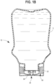
FIG. 1B is a cross sectional view of the bottle ofFIG. 1A in an inverted position. -
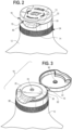
FIG. 2 is a perspective view of a cap and a portion of a bottle useful for understanding the present invention. -
FIG. 3 is a perspective view of the cap ofFIG. 2 in an open configuration. -
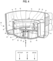
FIG. 4 is a perspective cross sectional view of a portion of a cap useful for understanding the present invention in an inverted orientation. -
FIG. 5 is a perspective view of an underside of a portion of a cap useful for understanding the present invention with a disk removed therefrom. -
FIG. 6 is a perspective view of an underside of a disk useful for understanding the present invention. -
FIGS. 7A and7B are top and bottom plan views of the disk. -
FIG. 7C is an elevational side view of the disk ofFIGS. 7A and7B . -
FIG. 7D is a cross section alongline 7D-7D ofFIG. 7B . -
FIG. 7E is a cross section alongline 7E-7E ofFIG. 7B . -
FIG. 8 is a perspective cross sectional partial view of the cap in a closed configuration with the disk removed therefrom useful for understanding the present invention. -
FIG. 9 is a perspective cross sectional view of a portion of the cap without the disk attached thereto useful for understanding the present invention. -
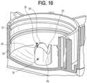
FIG. 10 is a perspective cross sectional view of a portion of the cap without the disk attached thereto useful for understanding the present invention. -
FIG. 11 is a perspective cross sectional view of a portion of the cap. -
FIG. 12 is a cross sectional view of a portion of the internal shaft at the cap opening. -
FIG. 13 is a cross sectional view of a portion of the internal shaft at the cap opening. -
FIGS. 14 and 15 are partial cross sectional views of a portion of alternative caps. -
FIGS. 16 and 17 are partial cross sectional views of a portion of the cap useful for understanding the present invention. -
FIG. 18 is a perspective cross sectional view of a portion of a cap showing an alternative. -
FIG. 19 is a cross sectional view ofFIG. 18 . -
FIG. 20 is a perspective cross sectional view of a portion of a cap showing an alternative. -
FIG. 21 is a cross sectional view ofFIG. 20 . -
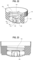
FIG. 22 is a perspective cross sectional view of a portion of a cap showing an alternative. -
FIG. 23 is a cross sectional view ofFIG. 22 . -
FIG. 24 is a side view of a cap in an open configuration useful for understanding the present invention. -
FIGS. 25 and 26 are partial cross sectional views of the cap ofFIG. 24 . -
FIG. 27 is a side view of another cap in an open configuration useful for understanding the present invention. -
FIGS. 28 and 29 are partial cross sectional views of the cap ofFIG. 27 . -
FIG. 30 is a side view of another cap in an open configuration useful for understanding the present invention. -
FIGS. 31 and 32 are partial cross sectional views of the cap ofFIG. 30 . -
FIGS. 33 and 34 are cross sectional views illustrating alternative mixing chambers. -
FIGS. 35-37 are partial cross sectional views illustrating alternative internal shafts. -
FIG. 38 is a cross section of a cap having detailed portions magnified to show various finishing options for the internal shaft. -
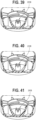
FIGS. 39-44 are partial perspective views having a portion removed therefrom illustrating alternatives of the internal shaft of the base. -
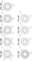
FIGS. 45A-45I are top plan views of alternatives of the disk. -
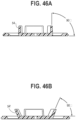
FIGS. 46A and 46B are cross sections of alternatives of the disk. -
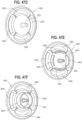
FIGS. 47A-47I are perspective views of an underside of alternatives of the disk. -
FIG. 48 is a partial cross sectional view of a portion of an alternative cap useful for understanding the present invention. -
FIG. 49 is a partial cross sectional view of an alternative cap according to the present invention. -
FIG. 50 is a partial cross sectional view of another alternative cap according to the present invention. -
FIG. 51 includes a perspective view of a portion of an alternative cap. - Elements in the figures are illustrated for simplicity and clarity and have not necessarily been drawn to scale. For example, the dimensions and/or relative positioning of some of the elements in the figures may be exaggerated relative to other elements to help to improve understanding of various embodiments of the present invention. Also, common but well-understood elements that are useful or necessary in a commercially feasible embodiment may be omitted in order to facilitate a less obstructed view of these various embodiments of the present invention. Certain actions and/or steps may be described or depicted in a particular order of occurrence when such specificity with respect to sequence is not actually required. The terms and expressions used herein have the ordinary technical meaning as is accorded to such terms and expressions by persons skilled in the technical field as set forth above except where different specific meanings have otherwise been set forth herein.
- Described herein are systems, apparatus and methods that are useful to dispense a fluid, such as, for example, a thixotropic fluid, from a bottle. Some embodiments include a closure cap for such a bottle. The closure cap may include a flip-top, a base, and a disk, where the base and disk define a mixing chamber configured to facilitate mixing of the fluid, which may mix serum or liquid separated from the fluid back therein. In some configurations, the base has a central opening through which the fluid exits, and a hollow internal shaft with a non-planar end surface opposite a central opening, with the non-planar end surface and the disk defining one or more channels between the mixing chamber and the interior of the shaft. (In other configurations, the shaft may have a planar end surface opposite the opening, and the shaft may have apertures formed therein.) In some embodiments, the disk includes a central opening, a plurality of partial annular openings through a planar surface of the disk, and projections extending into the mixing chamber. To exit the bottle, the fluid is advanced from the reservoir or body of the bottle through the openings in the disk (e.g., the partial annual openings or the central pinhole) and through the chute formed by the internal shaft and out the central opening of the base. The fluid is advanced through these openings and pathways by having a user apply manual pressure to the body of the bottle.
- In some embodiments, the dispensing bottle includes a container body having a neck with external threads thereon that engage internal threads on a closure cap that includes a base and a flip-top lid. In one illustrative embodiment, the base of the closure cap has a skirt with base threads disposed thereon, where the base threads are configured to engage the external threads on the neck of the bottle. Further, in some embodiments, the base includes one or more retaining elements, projections, or rings on an internal surface of the base (such as on the internal surface of the skirt) and a central portion having an opening therein aligned with an internal shaft, where the opening permits the fluid to egress therethrough when the opening is unobstructed. By one approach, the internal shaft terminates at a non-planar end surface opposite the central portion. Further, this internal shaft may have a disk mounted adjacent thereto.
- As noted, the cap has a flip-top lid, and in one illustrative configuration, the flip-top lid has an interior projection that is movable between a closed first position to an open second position, where the projection blocks the opening of the base, preventing or inhibiting egress of the fluid from inside the container body in the first position and, in the second position, permits egress of the fluid through the opening of the base. In addition, in one illustrative embodiment, a disk is attached to an interior of the base by snapping the disk into position at retaining ring(s), the disk having a central pinhole and partial annular slots disposed around the central pinhole. In one exemplary configuration, a mixing chamber is formed by the disk and the central portion of the base, along with the skirt and the internal shaft. Further, in some configurations multiple fluid channels are formed by the non-planar end surface of the internal shaft and the disk permitting fluid to flow from the mixing chamber into the internal shaft.
- In some embodiments, the closure cap, in the closed position, is capable of maintaining the thixotropic fluid in stable equilibrium in the bottle without leakage when the bottle is in an inverted position such that the bottle opening is positioned below the body of the container. In some embodiments, when the closure cap is in the open position, during application of pressure to the container body, the configuration of the closure cap enables controlled dispensing of the thixotropic fluid, and release of pressure on the container body enables prompt cessation of dispensing, such as, for example, by permitting air to flow back into the container body to allow for spring back of the bottle and reversal of flow of thixotropic fluid in the interior channel. Further, in one illustrative configuration, this occurs without movement of the disk relative to the base. By one approach, the spring back is achieved by permitting air to be able to quickly enter the bottle to replace the volume of fluid that has been dispensed, which permits the bottle to quickly recover its original shape.
- In one illustrative approach, at least a portion of fluid is dispensed by advancing downward through the partial annular openings, through the mixing chamber, then inward through the fluid channels defined between the disk and the nonplanar end of the internal shaft, then downward through the interior of the shaft before exiting the dispensing bottle via the central opening. By one approach, a thixotropic fluid disposed in the bottle can be squeezed from the bottle such that it advances through the partial annular slots in the disk, and through the mixing chamber where any separated serum can be mixed into the fluid before the thixotropic fluid moves through channels formed by an end of the internal shaft and the disk and out the central opening of the base. Further, a portion of the fluid also may advance downward through the small aperture or pinhole in the disk and through the central opening of the base. As suggested above, in operation, the bottle is able to quickly regain its shape upon cessation of pressure on the bottle. Air may flow into the bottle via one or both of these pathways, e.g., through the pinhole in the disk and/or through the annular openings, such that air is able to flow into the bottle through the internal chamber, channels, pinhole, mixing chamber, and/or partial annular slots. Generally, the air is pulled into the bottle when pressure is released on the body of the bottle or container. Thus, in short, the air is admitted into the main cavity of the bottle by flowing through at least one of the central pinhole or the partial annular slots of the disk. Further, once the disk is installed into the base of the closure cap, by one approach, the disk remains stationary relative to the base.
- In some embodiments, the closure cap, including the base, flip-top, and disk are generally comprised of a polypropylene material, such that the entire closure cap is recyclable as a unit. In addition, without a silicon membrane, the strength of the closure in some embodiments does not significantly degrade over time, and there is little or no degradation of its performance over time. In some embodiments, there is little or no variation in the pressure required to dispense fluid from the bottle over the life of the bottle.
- As described herein, the closure cap may permit better dosing. It may prevent accidental high velocity discharge of product from the bottle, which can be messy, and may prevent permanent collapse or other permanent inward deformation of the bottle. Further, the closure cap configuration may reduce splatter. Also, as described below, the mixing chamber may be configured to facilitate cleaning of its exterior surface, e.g., by having an outwardly convex or dome-shaped exterior surface.
- By one approach, the outside, bottom (when the bottle is inverted) surface of the base, adjacent the central opening through which the fluid is dispensed, has an arcuate or dome-shaped central portion with a planar peripheral surface therearound. In one example, the inside of the base has the internal shaft extending at least somewhat parallel to the skirt of the base. In some configurations, the base includes an internal cut-off blade disposed adjacent the central opening, where an inner diameter of the internal shaft is sharply reduced. By one approach, the cut-off blade has an edge that is sharp, without a burr thereon. In some configurations, an inner diameter of the opening itself is different from the internal shaft wall. More particularly, in such a configuration, the diameter of the opening into the container is smaller than the diameter between the walls of the internal shaft, and this reduction in size and the relatively sharp edge therebetween helps facilitate reduction of the tailing formation of the product by partially retaining the product in the closure. Also, the surface tension and the size of the opening also can help reduce the tailing formation of the product as well. While this cut-off blade does not prevent product from flowing out of the opening in the closure cap, it reduces the amount released under certain pressures by slowing the flow. By one approach, the cut-off blade is relatively small compared with the diameter of the shaft and in some configurations the internal cut-off blade has a width of about 1 mm, while the diameter of the opening into the container itself is about 3mm to about 7mm. In another configuration, the opening has a diameter of about 3.5mm to about 4.5mm. In yet another embodiment, the opening has a diameter of about 4mm and the diameter of the internal shaft is about 6 mm. Accordingly, the cut-off blade has a width of about 1mm in some configurations.
- While the cut-off blade assists with rapid cessation of fluid dispensing, upon release of pressure on the bottle, the disk (and its interface with the internal shaft) also reduces the pressure caused by the product in the bottle, which assists with cessation of dispensing. As discussed below, the size and configuration of the openings in the disk assist with flow monitoring and depending on the viscosity and surface tension of the product, and the geometry of the disk may be adjusted to accommodate different fluids.
- At the upper end of the internal shaft, disposed away from the opening in the base, the internal shaft, in some embodiments, has a non-planar end surface. By one approach, the non-planar end surface has a stepped configuration creating a plurality of teeth and depressions. By another configuration, the non-planar end surface is configured with a wavy, sinusoidal or other arcuate depression.
- As suggested above, the bottle and cap described herein may be employed for use with a wide variety of fluids. In one illustrative configuration, the bottle is filled with a thixotropic fluid, such as, for example, certain condiments, sauces, or certain consumer items, such as shampoo or body wash. Such applications may be particularly advantageous because they permit the consumer or user to easily and quickly dispense a desired amount of fluid without splattering or otherwise creating an unintended mess with the fluid. By one approach, the dispensing bottle with the closure cap may have a capacity of about 250 mL to about 1000 mL. Further, a variety of container configurations are contemplated, including some that are stored in an inverted configuration where the bottle rests on the closure cap. In one illustrative approach, the disk has a diameter of between about 20 to about 40mm, the internal shaft has a height of between about 4 to about 12 mm, and the internal shaft has a diameter of about 3 to about 9 mm. In other configurations, the internal shaft has a height of about 5 to about 9mm, with a diameter of about 3-5 mm.
- As noted above, the closure cap has a mixing chamber formed by a portion of the base that has a disk secured thereto. By one approach, the mixing chamber includes a plurality of extensions therein from the disk. More particularly the disk, in some configurations includes a plurality of extensions of flanges that extend downward from the bottom of the disk (with the bottle inverted) into the mixing chamber. The mixing chamber described herein helps prevent serum from leaking from the dispensing bottle, in part, by mixing serum that has separated from the thixotropic fluid back into the remainder of thixotropic fluid. By one approach, the mixing chamber prevents separated serum from leaking from the bottle by mixing the separated serum back into the fluid before it leaves the opening of the bottle. In some embodiments, the mixing chamber has a capacity of, or retains, 2mL to 11mL, 3mL to 9mL, or 5 to 7mL, or about 6mL. The disk extensions may help with remixing of separated serum by slowing the flow of the fluid through the mixing chamber, creating or increasing turbulence, and/or otherwise increasing interaction between separated serum and the remainder of the fluid.
- By one approach, multiple retaining rings may be provided, and one of those rings may have a bottle or cap liner associated therewith that may seal the bottle after the closure cap is attached thereto. For example, a first retaining ring and a second retaining ring may be spaced axially (vertically) from each other with an edge of the disk captured therebetween. The upper ring (with the bottle inverted) may have a removable film or liner member associated therewith that seals against the opening at the neck of the bottle before use. Prior to dispensing product, the liner member may be manually removed by a consumer.
- A bottle with a closure cap described herein may be formed, filled and sealed in high speed, high volume, mass production operations, or in other types of operations. In one approach, a method of manufacturing a dispensing bottle generally includes forming a squeezable, flexible bottle, e.g., by blow molding, injection molding, or other methods; forming a disk and a closure cap having a base and a flip-top lid by injection molding or other methods; snapping the disk into the base; filling the receptacle with a fluid (such as, for example, a thixotropic fluid); and securing the closure cap onto the filled receptacle. In some embodiments, the base has inner and outer skirts with base threads on the interior of the inner skirt (where the base threads are configured to engage the threads on the exterior of the bottle neck), a retaining ring on the interior of the inner skirt, and a central, dome-shaped portion having an opening therein aligned with an internal shaft terminating at a non-planar end surface opposite the central opening. The dome-shaped portion includes an opening permitting fluid to egress therethrough when the opening is unobstructed, and the flip-top lid has an interior projection that is movable between a first position and a second position, where the projection blocks the opening of the base inhibiting or preventing egress of the fluid when in the first position, and permits egress of the fluid through the opening of the base when in the second position. In some embodiments, the disk has a central pinhole, and partial annular slots disposed around the central pinhole, wherein the disk, the central portion of the base, the inner skirt, and the exterior surface of the internal shaft define a mixing chamber, and wherein multiple fluid channels are formed between the non-planar end surface of the internal shaft and the disk. In some configurations, the method also includes sealing the receptacle with a removable liner associated with the closure cap to seal the product in the body of the bottle. As discussed further below, the base and flip-top lid may be molded with the disk or separately therefrom.
- In one illustrative configuration, a closure cap for a container includes a flip-top lid and base having, at least, a dome-shaped wall with an opening therethrough, an inner skirt, an outer skirt connected by an upper, planar portion, threads and one or more retaining rings on the inner skirt, and an internal shaft inwardly depending from the dome-shaped wall. By one approach, the internal shaft terminates at a non-planar end surface. Further, in such a configuration, the flip-top lid has a projection and is movable between a first position where the projection blocks the opening and a second position where the projection does not obstruct the opening of the base. The closure cap, in some configurations, has a disk attached to an interior of the base by snapping the disk into the retaining ring(s). In such a configuration, the disk has a central pinhole, partial annular slots disposed around the central pinhole, and flanges extending toward the base, the flanges disposed in between the internal shaft and the partial annular slots when the disk is attached to the base. Further, by one approach, the closure cap includes a mixing chamber defined by the disk, the dome-shaped wall, the inner skirt, and the internal shaft, wherein multiple fluid channels are formed by the non-planar end surface of the internal shaft and the disk.
- In another approach, a method of manufacturing a closure cap includes forming, in a mold, a flip-top cap with (a) a base having, at least, a dome-shaped wall with an opening therethrough, an inner skirt, an outer skirt connected by a planar portions, threads and a retaining ring on the inner skirt, and an internal shaft inwardly depending from the dome-shaped wall, the internal shaft terminating at a non-planar end surface, and (b) a flip-top lid hingedly connected to the base, the flip-top lid having an interior projection and being movable from a first position where the interior projection blocks the opening to a second position where the interior projection does not obstruct the opening of the base. Further, in some approaches, the method also includes snapping a disk into the retaining ring of the base of the flip-top cap, the disk having a central pinhole, partial annular slots disposed around the central pinhole, and flanges extending toward the base, the flanges disposed in between the internal shaft and the partial annular slots when the disk is attached to the base. Further, in some embodiments, the disk and the base form a mixing chamber defined by the disk, the dome-shaped wall, the inner skirt, and the internal shaft, wherein multiple fluid channels are formed by the non-planar end surface of the internal shaft and the disk.
- Further, in some configurations, the method also includes forming the closure cap as two separate components, including the flip-top cap and the disk, where the flip-top cap includes the base and flip-top lid formed in a single, integral, unitary, one-piece structure, and wherein the two separate components are made of the same material, and are assembled at the mold or at a separate station.
-
FIGS. 1A and1B illustrate a packaged food product comprising abottle 10 containing afluid food product 5 such as ketchup, mayonnaise, barbecue sauce, mustard, or another product, with aclosure cap 18 attached to acontainer body 12 via internal threads 32 (see, e.g.,FIG. 4 ) of theclosure cap 18 engagingexternal threads 16 of thecontainer body 12. A portion of theclosure cap 18 is shown transparently inFIG. 1A for illustrative purposes. WhileFIG. 1A shows the bottle in an upright position, in some configurations, thebottle 10 is configured to be stored inverted while resting on its closure cap, such as that shown inFIG. 1B . Accordingly, during storage and dispensing, thebottle 10 may have theclosure cap 18 positioned below thecontainer body 12 of thebottle 10 without unintended leakage of the fluid 5 from thebottle 10. - The
closure cap 18, as shown inFIGS. 2 and 3 includes abase 20 and a hinged or flip-top lid 22. To open thebottle 10 to permit thefluid 5 to be easily dispensed therefrom, a user may pivot the flip-top lid 22 from the closed configuration ofFIG. 2 to the open configuration ofFIG. 3 . To that end, a user or consumer may apply upward force to thelid 22 by engaging the mouth-shapedindentation 70 defined by theupper surface 72 and alower surface 74. By one approach, a user will manually grasp and pull upward on theupper surface 72 pulling it away from thebase 20 and a remainder of thebottle 10. The flip-top lid 22 then pivots about ahinge 19 opposite the mouth-shapedindentation 70 to sit stably in the open configuration. - As can be seen in
FIG. 3 , when the flip-top lid 22 is in the open configuration, aprojection 90 of the flip-top lid 22 is moved from obstructing or blocking anopening 34 in the base 20 to a position away therefrom such that theopening 34 is unobstructed.FIG. 3 also illustrates acentral portion 30, which may be dome-shaped, through which theopening 34 extends, and aplanar portion 62 disposed at least partially therearound. Thelower surface 74 of the mouth-shapedindentation 70, as shown in the illustrative example ofFIG. 3 , extends between sections of theplanar portion 62. -
FIG. 4 illustrates a perspective cross-sectional view of a portion of theclosure cap 18 in an inverted orientation. As shown inFIG. 4 , thebase 20 includes aninner skirt 26, upon which theinternal threads 32 and one or more retaining rings 44 are disposed, anouter skirt 28, aplanar portion 62 therebetween, and a dome-shapedcentral surface 30 having anopening 34 disposed therein. One or more radial stiffeners or strengtheningribs 76, shown inFIG. 4 , are disposed between theouter skirt 28 and theinner skirt 26. As shown in the illustrative configuration ofFIGS. 4 and5 , thebase 20 includes aninternal shaft 36 extending upward away from the central dome-shapedsurface 30 and terminating at a non-linear surface 38 (as shown inFIG. 5 ). - In one illustrative example, the
closure cap 18 includes a disk 42 (shown inFIGS. 4 and6 ) with a plurality of openings therein, through which thefluid 5 and air can flow. By one approach, the retaining rings 44 disposed on the inner wall of theinner skirt 26 capture thedisk 42 therebetween. In another configuration (not shown), thedisk 42 may be captured between a retaining ring and another structure, such as, for example, a portion or extension of theinternal shaft 36.FIG. 4 , illustrates a cross section of a portion of theclosure cap 18 having thedisk 42 snapped in between two retainingrings 44, illustrates how thedisk 42 and the base 20 form a mixingchamber 56. In one illustrative example, the mixingchamber 56 is formed by the walls of theinner skirt 26, thecentral portion 30, theinternal shaft 36 of thebase 20, and thedisk 42. - Further, the
planar potion 62 of thebase 20 joins theinner skirt 26 andouter skirt 28 as well. As shown inFIG. 1 , thebase 20 also hasribs 80 disposed on the portion of thebase 20 below (with the bottle in an upright orientation) the flip-top lid 22. These ribs provide a gripping surface such that if someone wanted to remove theentire closure cap 18 from thecontainer body 12, the user is able to more easily grasp theclosure cap 18 to disengage theinternal threads 32 of the base 20 from theexternal threads 16 of theneck 14. In other configurations, theribs 80 may be removed from theclosure cap 18. -
FIGS. 5 and9 illustrate one exemplary non-linear terminatingsurface 38 of theinternal shaft 36 of thebase 20. In some examples, the non-linear terminatingsurface 38 forms channel openings for both the fluid and air to travel between the mixingchamber 56 and theinternal shaft 36. By one approach, the non-linear terminatingsurface 38 has a steppedconfiguration 64, as shown inFIGS. 8 and 9 . In yet another approach, the non-linear terminatingsurface 38 has a wavy, sinusoidal or other arcuate configuration. In some configurations, the non-linear terminatingsurface 38 may have semi-circular depressions cut into the wall of theinternal shaft 36. In addition, a single or a number of depressions may form one or more channels between the mixingchamber 56 and theinternal shaft 36. - Further, the stepped
configuration 64, which is shown inFIGS. 5 and9 , may include one or more projectingteeth 68, and one or moredeep slots 66 extending from a mid-point therebetween, or otherwise positioned. The steppedconfiguration 64 of the non-linear terminatingsurface 38 of theinternal shaft 36 cooperates with the surface of the disk to form thefluid channels 58 having varying width and/or depth. As shown inFIG. 10 , the non-linear terminatingsurface 39 also may have a wavy or an arcuate configuration with multiple slots ordepressions 65 androunded extensions 69. The wavy, non-linear terminatingsurface 39, which operates similar to the stepped configuration discussed above, formschannels 58 with thedisk 42. In some configurations, the non-linear terminating surface may have a combination of stepped portions, projections, angles, and/or curved sections, among other elements. - Indeed, the non-linear terminating
surface 38 may take a variety of configurations, such as, for example, those illustrated inFIGS. 8-10 and39-44 . As discussed above, the non-linear terminatingsurface 38, shown inFIGS. 5 and9 , has a stepped configuration forming a number ofchannels 58. Further, in another configuration, the non-linear terminatingsurface 39, shown inFIG. 10 , has a wavy or sinusoidal configuration.FIG. 39 illustrates a non-linear terminating surface 2238 that has two different heights, as opposed to the three different heights illustrated inFIGS. 8 and 9 .FIG. 40 illustrates a non-linear terminating surface 2338 that has two heights and angled portions therebetween.FIG. 41 illustrates anon-liner terminating surface 2438 that has generally v-shaped valleys disposed in between prongs or projections having a triangular-shaped cross section.FIG. 42 , similar toFIG. 39 , illustrates a non-linear terminatingsurface 2538 having two different heights, but the prongs or projections ofFIG. 42 have a triangular shape or a trapezoid shape with more acute or smaller angles adjacent the larger base.FIG. 43 illustrates a non-linear terminatingsurface 2638 having a stepped configuration, where the lowest step has a smaller width than the width of the uppermost step. Finally,FIG. 44 illustrates a non-linear terminatingsurface 2738 with triangular-shaped prongs or projections having u-shaped valleys therebetween. It is noted that the features illustrated may be used as shown or combined with other exemplary features including, for example, those shown in other figures. Alternatively, the end of the shaft may be linear or flat and the shaft may include other openings incorporated therein. - In addition to forming, in part, the mixing
chamber 56, thedisk 42 also defines annular partial slots oropenings 50 therein to permit flow of fluid (and its constituent parts) into the mixing chamber. Theannular openings 50 may take a variety of configurations, such as, for example, those illustrated inFIGS. 7A ,7B , and45A-45I . By one approach, shown inFIGS. 7A and7B , thedisk 42 includes four openings. In another example, shown inFIG. 45A , thedisk 1142 has two openings. In another example,FIG. 45B includes threeannular openings 1250, whereas the example ofFIG. 45C includes fiveopenings 1350.FIG. 45D illustrates anexemplary disk 1442 with sixopenings 1450, whereasFIG. 45E illustrates anexemplary disk 1542 with sevenannular openings 1550. Theexemplary disk 1642, shown inFIG. 45F , includes eightannular openings 1650 and an offset pinhole 1648, whereas the pinholes inFIGS 45A-45E and 45G-45I are centrally disposed in the disks shown therein. Further, while the corners of the annular opening illustrated inFIGS. 7A ,7B , and45A-45F are rounded, lacking any sharp edges or pinch points,FIGS. 45G-45I illustrate openings with lessrounded openings -
FIGS. 47A-47I also illustrate a number of exemplary disks with a variety of features that may help manage the flow of the fluid from the bottle and through the cap. As mentioned above, the bottle is often stored and/or used in a top-down position, such that serum that separates in the chamber may leak from the bottle, in part, because it may not have a particularly long flow path or time with which to mix back into the fluid before advancing through being moved out of the bottle cap. - To facilitate the mixing of any separated serum with the remainder of the fluid, the disk may incorporate a number of additional features, such as, for example, additional openings disposed interior of the flanges thereof. In one illustrative example, these openings are intermediate to the annular slots and the center of the disk, which may have central pinholes, as discussed above. One
illustrative disk 2042, shown inFIG. 47A includesannular openings 2051 that are interior to theflanges 2054, which are themselves interior to the larger annular openings orslots 2050. In this manner, there are smaller,interior openings 2051 adjacent the inner wall of theflange 2054 that assist with mixing the fluid and any separated constituent elements thereof.FIGS. 47B and 47C similarly illustrateexemplary disks interior openings adjacent flanges slots FIGS. 47A and to each other. In addition,FIG. 47C lacks a central pinhole, whereasFIGS. 47A and 47B include a central opening in the disks illustrated therein. In addition to these configurations, the pinhole also may be disposed offset from the geometric center of the disks as well, as previously suggested above. -
FIGS. 47D-47F illustrate additional illustrative examples of a disk with a post extending therefrom to facilitate mixing of the fluid as it moves through the cap. Once installed or secured to a remainder of the cap, the post typically extends toward the exit or opening of the bottle. For example, the exemplary disk 2342 (FIG. 47D ) includesannular openings 2350 and a centrally disposed post 2353 having relatively smooth sides thereof. Theillustrative disk 2442 illustrated inFIG. 47E includesannular openings 2450,flanges 2454, and a centrally disposedpost 2453. Whereaspost 2353 has relatively a rounded exterior, thepost 2453 has uneven sides, with a cross section having a generally x-shaped configuration. - While the post is shown centrally disposed, it also may be disposed off-center and multiple posts may be incorporated into the disk. Further, the post may have a variety of surface textures and configurations. Indeed, depending on the fluid moving through the cap, a variety of differently configured posts may be incorporated into the cap.
- In some configurations, instead of a post, the disk may have another, similar structure such as a cone. FIG. 471 illustrates the central portion of a
disk 2842 having a cone shapedextension 2857 with anopening 2848 extending therethrough. In addition, thedisk 2842 also includesannular openings 2851,flanges 2854, andopenings 2850. - The
disk 2542 ofFIG. 47F , similarly has a centrally disposed post 2553 with a generally x-shaped cross section andannular openings 2550. Instead of discrete flanges, however, thedisk 2542 has one continuous flange or acylindrical wall 2555 extending from thedisk 2542. While thecylindrical wall 2555 is illustrated generally perpendicular to the disk, it also may extend from the disk at an angle, similar to how the flanges illustrated inFIG. 46B are not perpendicular. -
FIG. 48 illustrates thedisk 2542 secured to a remainder of theclosure cap 2518. Furthermore, thepost 2553 is illustrated as extending at least partially intointernal shaft 2536. In this manner, the fluid must advance throughannular openings 2550, over or around thecylindrical wall 2555, over or around the end of theinternal shaft 2536 and through the shaft, along thepost 2553 to theopening 2534. Such configurations, having a somewhat winding flowpath, may be particularly suited for certain fluids with particular fluid properties. - Other modifications or combinations of the features described herein may be made. For example,
FIG. 47G illustrates adisk 2642 that is similar to thedisk 2142 ofFIG. 47B , however,flanges 2654 are not as long as those illustrated inFIG. 47B such that the fluid has more room or space to move between theflanges 2654 ofFIG. 47G , as compared to those inFIG. 47B . In addition,FIG. 47H illustrates adisk 2742 having outerannular openings 2750adjacent openings 2751 without flanges disposed therebetween. Many of the various structural features of the disks may be combined or modified in a variety of manners, including those described herein, to tailor the disk to accommodate the properties of the fluid advancing from the bottle through the cap thereof. - As noted above, the mixing
chamber 56 and the openings formed in thedisk 42 by thedisk 42 and theinternal shaft 36 permit accurate dispensing and dosing of thefluid 5 within the container. Accordingly, the geometry of thedisk 42 helps facilitate the proper dispensing of thefluid 5. -
FIG. 7A illustrates a first side of thedisk 42 which hasflanges 54 extending downward therefrom when the bottle is inverted, and which faces theinternal shaft 36 when thedisk 42 is mounted in position between the retaining ring(s) of theclosure cap 18. While theflanges 54 may extend orthogonally from a face of the disk 42 (as shown inFIGS. 7C-7E ), theflanges 54 also may extend from thedisk 42 at an angle besides 90°. Turning briefly toFIGS. 46A and 46B , two illustrative flange configurations are illustrated.FIG. 46A illustrates theflanges 54 extending about 90° from the body of thedisk 42, whereas inFIG. 46B the flanges 54' extend less than 90° from the body of thedisk 42. Such an angled flange may impact the flow of theproduct 5 entering the mixingchamber 56 and may influence the mixing action in the chamber. While both the flanges shown in bothFIGS. 46A and 46B help mix the product as it advances toward the exit, depending on the fluid characteristics of the product, the angle of the flange 54', as shown inFIG. 46B may be smaller than 90°. As mentioned above, thecentral pinhole 48, which is centrally disposed through a planar portion of thedisk 42, is partially surrounded by a plurality of slots or partialannular openings 50. The peripheral, partialannular openings 50 are significantly larger than the central pinhole, and a majority of thefluid 5 exiting thebottle 10 advances through the partialannular openings 50. In some examples, thedisk 42 has a diameter, D1, of 20mm to 40mm, 25mm-35mm or about 30-34mm. In one illustrative configuration, thedisk 42 has a diameter, D1, of about 31.9 mm ±0.1mm. By one approach, the annular slots have an arcuate length of 10-15mm, or 11-14mm. As shown inFIG. 7B , the arcuate length A1, of each of the openings may be about 12.7mm. Further, theannular openings 50 have an inner radius of curvature R1 on the inner edge of the opening and an outer radius of curvature R2 on the outer edge of the opening. In one illustrative approach, Ri is about 6-10mm and R2 is about 10-15mm. In another illustrative approach, Ri is about 8-9mm and R2 is about 12-13mm. In one exemplary example, Ri is about 8.3mm and R2 is about 12.3mm. - As shown in
FIGS. 6 and7A , the partialannular openings 50 are disposedadjacent flanges 54, which, when thedisk 42 is installed in thebase 20, extend into the mixingchamber 56 such that the fluid 5 (including any constituent parts, such as serum) cannot advance directly through theopenings 50 and into theinternal shaft 36 to exit the bottle, but instead, the portion offluid 5 that advances throughopenings 50 must flow into the mixing chamber 56 (thereby promoting the mixing of any constituent parts of thefluid 5 that have separated therefrom) before the fluid exits thebottle 10. In one illustrative approach, the extensions orflanges 54 have a height, hi that is about 2-5mm. In another illustrative approach, the height hi is about 3-4mm. In one exemplary example, h1, is about 3.5mm. Further, in operation, the length or height of theflanges 54 may be linked to the depth of thechannels 58 formed by the non-linear terminatingsurface 38 because having them similarly sized helps facilitate mixing by requiring that the fluid flow around theflanges 54 and not directly through theannular openings 50 and through thefluid channels 58. In one illustrative approach, the height of thedisk 42, h2, is about 3-7mm. In another illustrative approach, the height of thedisk 42, h2 is about 4-6 mm. In yet another approach, the height of thedisk 42, h2, is about 4.8 mm. - The width, w1, of the planar portion of the
disk 42, as shown inFIG. 7D , in some examples is between about 0.75 mm to about 3mm. In one illustrative approach, the width of thedisk 42, w1, is about 1-2 mm. In one exemplary approach, the width of thedisk 42, w1, is about 1.3 mm. The width of thecentral pinhole opening 48, as shown in,FIG. 2 as d2, is about 1-2 mm. In one exemplary approach, the width of thepinhole 48, d2 is about 1.5 mm. - As shown in
FIG. 7E , each of the partialannular openings 50 may have a beveled edge on a surface of thedisk 42 facing thebase 20. This orientation may facilitate flow of fluid 5 (e.g., at least a portion of the fluid not retained in the internal shaft 36) back into thecontainer body 12 when the bottle is placed in the cap-side up (upright) configuration. Further, the beveled edge also may facilitate moving the air back into the bottle to improve spring-back of the bottle orcontainer body 12. - To facilitate proper dispensing of the fluid, the geometry of the
disk 42 regulates the flow of thefluid 5 including for example, the size, shape, and angle of theflanges 54. In addition to the geometry discussed above, thedisk 42 has sufficient openings therein relative to the area of thedisk 42 to facilitate sufficient flow of thefluid 5, while nonetheless preventing leakage from theclosure cap 18. Theopenings 50 are of a particular size, shape, and position to facilitate fluid flow that permits easy dispensing and quick spring back of the bottle. In one illustrative approach, the entire area of the disk is about 800 mm2 and the aggregate area of the partialannular openings 50 and the central pinhole is about 211 mm2 of that total area, or about 26% of the total area of the disk. By some approaches, the aggregate area of the openings of the disk will cover about 20-35% of the total disk area, and generally the partial annular openings comprise much more of this area than the central pinhole. - In
FIG. 4 , flow of ketchup during dispensing is shown as a dashed line. Flow of air into the bottle to replace ketchup after dispensing is shown as a heavy solid line. A lighter solid line illustrates flow of serum that has separated from thefluid 5, into the mixingchamber 56 where it mixes back into thefluid 5. - In some illustrative approaches, the closure cap 18 (e.g., the
base 20, the flip-top lid 22, and the disk 42) is comprised of a single material, such as, for example, a polypropylene or other food grade plastic or polymer, or similar recyclable material. In operation, having theclosure cap 18 formed of a single material may increase the ease and likelihood of recycling the material. By some approaches, the material may be chosen with a specific surface tension. For example, thedisk 42 surfaces (and potentially other internal surfaces of the closure cap) may be rougher or textured to provide flow resistance and help control the flow of the fluid being dispensed. As discussed further below, the interior surface of theinternal shaft 38 also may be textured to inhibit flow or may have a smooth surface to facilitate movement of the fluid therethrough. A smooth surface may result in faster and/or less controlled fluid flow, and due to a reduction in surface tension, may also lead to leakage of the product or a separated component of the product. The finish of the material or the manner in which the element was formed also may impact the surface tension of the elements and help facilitate control of the fluid flow. For example, some portion of the flip-top cap 18 may be formed in such a manner as to create a rough surface that might impact the flow of thefluid 5 passing therethrough. - Turning briefly to
FIG. 38 , two differentexemplary finishes interior wall 78 may have the entire surface thereof with a single texture or portions of the surface with different textures, thecap 18 illustrated inFIG. 38 has afirst portion 2078 with arougher texture 77 and asecond portion 2178 with asmoother texture 79. As noted above, the surface of the material forming thecap 18 may inhibit, slow, or restrict flow of thefluid 5 within the bottle. Whether or not to include a textured surface on portions of or the entire cap, such as, for example, the inner wall of the internal shaft, may depend on the type of fluid being advanced through thecap 18. - As shown in
FIG. 6 , a first side of the disk 42 (which is disposed adjacent theinternal shaft 36 of the base 20 when installed) includes rainbow-shaped or arcuate flanges orextensions 54 that extend therefrom. When thedisk 42 is mounted in thebase 20, the arcuate flanges orextensions 54 extend into the mixingchamber 56 and toward thebase 20. Thedisk extensions 54 facilitate mixing of thefluid 5 in the mixingchamber 56 by requiring that thefluid 5 move around theextensions 54 and not directly into thefluid channels 58 from the partialannular openings 50. - As shown in
FIG. 8 , the base 20 at theopening 34 and theinternal shaft 36 has an internal cut-off blade orledge 60 on an inside surface adjacent the opening where the inner diameter of the internal shaft is sharply reduced. For example, the diameter of the internal shaft may decrease sharply at theledge 60 such that the sharp edge helps to facilitate reduction of the tailing formation of the product by partially retaining the product in the closure until the manual pressure on the container body becomes significant enough to overcome the tendency of the fluid to be retained in the closure cap by the ledge. By one approach, the cut-off blade has a sharp edge without a burr thereon. In some configurations, the diameter of the opening into the container is smaller than the diameter of the internal shaft, and this reduction in size and the relatively sharp edge therebetween assist with cessation of dispensing in a quick and clean manner. While this cut-off blade does not prevent product from flowing out of the opening in the closure cap, it reduces the amount released under certain pressures by slowing the flow. By one approach, the cut-off blade is relatively small compared with the diameter of the shaft, while the opening into the container itself is between about 3.5mm to about 4.5mm, and in one illustrative example, is about 4 mm. - As noted above, the
internal shaft 36 may help support thedisk 42 when the disk is attached to thebase 20. By one approach, the internal orinterior wall 78 of theinternal shaft 36 funnelsfluid 5 toward theopening 34. In one example, theinterior wall 78 forms at least one of a circular shape or a parabolic shape.FIG. 11 illustrates one example shape of aninterior wall 78 that narrows slightly near the exit of theinternal shaft 36. Further, in some examples, theshaft 36 may flare open again adjacent theopening 34. By flaring a bit where the opening meets the upper surface of the base, the opening permits theprojection 90 to more easily and quickly be placed in theopening 34 when closing the flip-top cap 18. In yet another configuration, shown inFIG. 12 , theinterior wall 78 has straight portions that are generally vertical and then has angled portions that direct thefluid 5 to theopening 34.FIG. 13 is similar to theinternal shaft 36 ofFIG. 12 , but further includes a cut-off blade 60 or sharp reduction in the diameter of theinternal shaft 36 to assist with cessation of dispensing of thefluid 5, as discussed above. Additional examples of cut-off blade configurations or internal projections around the opening are illustrated in.FIGS. 14 and 15. FIG. 14 illustrates anopening 134 with a cut-off blade 160 that has an inner surface that is angled slightly downward or toward the throughopening without a horizontal shelf extending therefrom, whereas the previously discussedFIG. 13 includes a downward angled portions but has a horizontal cut-off blade 60 extending therefrom. Further,FIG. 15 illustrates anopening 234 with a cut-off blade 260 having an inner surface that is angled away from the throughopening. -
FIGS. 16 and 17 illustrate two options for the configuration of the surface of the container or dome on the outside of theopening 34. For example,FIG. 16 illustrates a rounded edge at the juncture where thecentral portion 30 meets with theopening 34. Previously discussedfigures 14 and 15 have an angled depression around the opening at that location. Further,FIG. 17 illustrates adepression 161 with a sloping wall surface between thecentral portion 30 and theopening 34. - The
bottle 10 and theclosure cap 18 may be produced in a number of different manners. In one illustrative approach, a method of manufacturing or producing a filled bottle for dispensing fluid includes molding a receptacle, such as a container body with a threaded neck, filling the receptacle with a fluid, such as a thixotropic fluid, molding a closure cap having a base and a flip-top lid and a disk, and closing the filled receptacle with the closure cap. Further, a bottle may be formed and filled in-line or may be formed at one location and filled at another. - By one approach, the closure cap and disk are separately molded and snapped together. In some configurations, the molded base has an inner and outer skirt with base threads disposed on the inner skirt that are configured to engage the threads on the neck of the receptacle. Further, the molded base may have one or more retaining rings on the inner skirt (a short distance from the threads) and a central, dome-shaped portion having an opening therein aligned with an internal shaft terminating at a non-planar end surface opposite the central, dome-shaped portion. As mentioned above, the opening in the base permits fluid to egress therethrough when the opening is unobstructed. In some configurations, the molded flip-top lid has an interior projection that is movable between a first position and a second position, where the projection blocks the opening of the base inhibiting egress of the fluid inside the container body in the first position, and the second position permits egress of the fluid through the opening of the base.
- As mentioned above, the closure cap and disk, in some approaches, are separately molded and then secured to one another or snapped together. In such configurations, the method of manufacturing also may include an assembling step that orients the disk in a particular position relative to the remainder of the closure cap or
base 20. By including one or more orientation steps prior to assembling the disk with the remainder of the closure cap, the assembled caps are more likely to have a consistent flow rate therethrough. Further, in some configurations, the flow rate can be adjusted for different fluids by adjusting the relative positioning of certain elements of the closure cap or disk without requiring structural changes thereto. By one approach, a visual mark or indented notch disposed on one or both of the closure cap or disk may be used to help position the disk and/or closure cap relative to one another. - This may depend, in part, on the configuration of the various elements thereof. In one illustrative example, such as the
base 20 ofFIG. 5 , the non-linear terminatingsurface 38 of theinternal shaft 36 includes three cutouts, whereas thedisk 42 ofFIG. 6 , includes fourflanges 54. The flow of the fluid through the assembled closure cap may be impacted by the orientation of theflanges 54 relative to the cutout openings of theinternal shaft 36. Thus, these two structural elements may be oriented relative to one another to facilitate increased fluid flow therebetween or to slow fluid flow by requiring the fluid to take a longer pathway to the exit of the bottle. Given the interest in adjusting the fluid path or standardizing the flow rate for numerous closure caps, the method of manufacturing or assembling the closure cap and bottle may include orienting the disk in a particular manner relative to the remainder of the closure cap. - As suggested above, the method for producing the filled bottle may include snapping a disk into the retaining ring(s) of the closure cap. The molded disk, in some configurations, includes a central pinhole and partial annular slots disposed around the central pinhole. Once the disk is attached to the remainder of the
closure cap 18, thedisk 42, the central portion of thebase 20, theinner skirt 26, and theinternal shaft 36 of the base define a mixingchamber 56 and multiplefluid channels 58 are formed by the non-planar end surface of theinternal shaft 36 and thedisk 42. Thechannels 58 formed between the end of theinternal shaft 36 and thedisk 42 permit fluid to advance from the mixingchamber 56 to the chute formed by theinternal shaft 36 that is in communication with theopening 34. - The filled receptacle or container body, in some configurations, is sealed with the fluid therein by a liner associated with the closure cap. For example, a liner, such as a liner of a paperboard, plastic, and/or metallic material is associated with a portion of a retaining ring and when the
closure cap 18 is threadingly attached to the container body, the liner seals thefluid 5 in the container. - Further, in some approaches, a method of manufacturing a closure cap includes forming, in a mold, a flip-top closure cap including a base and a flip-top lid. In some examples, the molded base has a dome-shaped wall with an opening therethrough and an inner shaft extending therefrom, an inner skirt with threads thereon, an outer skirt connected to the inner skirt by a planar portion and/or possible strengthening ribs, and a retaining ring on the inner skirt. The internal shaft of the molded base generally extends inwardly from the dome-shaped wall and terminates at a non-planar end surface. Further, the molded closure cap also has a flip-top lid hingedly connected to the base, where the flip-top lid has an interior projection and is movable from a first position where the interior projection blocks the opening to a second position where the interior projection does not obstruct the opening of the base. The method of manufacturing the closure cap, in some configurations, further includes snapping a disk into the retaining ring(s) or projection(s) of the base. In some examples, the disk has a central pinhole, partial annular slots disposed around the central pinhole, and flanges, that when installed, extend toward the base and are disposed in between the internal shaft and the partial annular slots. Once the disk and base are attached, a mixing chamber is formed between the disk, the dome-shaped wall, the inner skirt, and the internal shaft, wherein multiple fluid channels are formed by the non-planar end surface of the internal shaft and the disk.
- In some configurations, the closure cap is made from only two separate components, including the flip-top cap and the disk, where the flip-top cap comprises the base and flip-top lid formed in a single, integral, unitary, one-piece structure, and wherein the two separate components (i.e., the flip-top cap and disk) are made of the same material, and are assembled. In operation, after the closure cap is molded and ejected from the mold, a mechanism can be used to assemble the disk into the closure cap (which can be formed at the same mold as the base and flip-top lid or at a different location), such as, for example, by snapping it into place in the base. Further, the mechanism or another device may be used to attach a liner to the retaining rings, which may help seal the fluid in the bottle. The base and flip-top lid, in some configurations, are molded in the same mold as the disk; in other configurations, the disk, along with the base and flip-top lid, are separately molded at the same mold. Further, the base and disk may be separately molded and assembled at another station. In yet other configurations, the entire closure cap (including the base, flip-top lid, and disk) might be molded or printed together.
- As mentioned above, a number of adjustments to the concepts described herein may be made while remaining consistent with these teachings. For example,
FIGS. 18 and 19 illustrate another example of a disk with annular openings. As shown, thedisk 342 has acentral portion 384 that is disposed a vertical distance from theperipheral portion 386, which has theannular openings 350 disposed therein. In such a configuration, the mixingchamber 356 may be designed to have a volume that is somewhat independent of the volume of the discharge shaft or chamber formed by theinternal shaft 356. Indeed, the mixingchamber 356 is somewhat smaller than some of the others discussed above. To permit the flow offluid 5 from the mixingchamber 356 to theinternal shaft 356 forming the discharge chamber, the radius of thecentral portion 384 may be sufficiently large enough, as compared to the radius of theinternal shaft 336 to provide clearance for thefluid 5 to pass from the mixingchamber 356 through the openings orfluid channels 358 formed between theinternal shaft 336 and the mixingchamber 356 and/or theopenings 358 may extend such that they have a height or location that is disposed beyond the vertical portion of thedisk 342 that may be disposed adjacent theinternal shaft 336. In short, the openings between the mixingchamber 356 and theinternal shaft 358 may be moved or sized to permit fluid flow even if thecentral portion 384 is not notably larger than the internal shaft. Further, while thecentral portion 384 is illustrated as lacking a central pinhole inFIGS. 18 and 19 , in some configurations, thecentral portion 384 may include such an air vent formed via a pinhole or other structure. In addition, thedisk 342 may be mated to the remainder of the cap in any of the manners, such as, for example, via a snap fit between portions of the base including ribs and/or projections or other complementary geometry between the disk and the base.FIGS. 20 and 21 illustrate another example of adisk 442, which lacks thecentral pinhole 48 found in some of the other examples. Also, whileFIGS. 18 and 19 do not include flanges similar to those described above, the vertical portion of the disk separating thecentral portion 384 and theperipheral portion 386 operates similarly to mix the product therein. - Turning to
FIGS. 22 and 23 , another example is illustrated and is a three-part solution having adisk 542 that is flat and an inner cap or innercylindrical housing 596. By one approach, the innercylindrical housing 596 includes acircular wall 592 with one ormore openings 598 disposed therein. In this manner, the mixingchamber 556 is in fluid communication with anintermediate chamber 594 defined, in part, by the innercylindrical housing 596. By one approach, the innercylindrical housing 596 is arranged in position about theinternal shaft 536 and held into place via thedisk 542 that is retained in position by the retainingmembers 544, such as rings. In addition, the innercylindrical housing 596 also may be securely attached to the central portion 530. When the innercylindrical housing 596 is disposed in position about theinternal shaft 536, thefluid 5 advances from the bottle to the exit or opening 534 by advancing through theannular openings 540, through theopenings 598 of theinner cap 596 and upward along the length of theinternal shaft 536 through the internal opening 588 of theinternal shaft 536 and down the shaft to theexit opening 534. As shown thedisk 542 includesannular openings 540 but lacks a central pinhole because the innercylindrical housing 596 lacks an opening in the surface thereof between thewalls 592. In this manner, thefluid 5 travels and mixes as it advances through the fluid channels of the three-part cap 518. In addition to mixing, this configuration may be particularly useful for larger containers where the downward force on the fluid when the container is inverted are quite large because of the significant amount of product that might be disposed above the cap. - Also, while
FIGS. 20-23 are not illustrated as including the flanges extending from the disk, in some configurations, the disks may include flanges similar to those described above. - The exterior shape of the central portion of the base also may have a variety of configurations. As noted above, the
central portion 30 of the base 20 may have a dome-shaped configuration, such as that incorporated into thecap 18 illustrated inFIG. 24. FIG. 25 illustrates a portion of a cross section of theexit 34 of the dome-shapedcentral portion 30 ofFIG. 24 . Further,FIG. 26 further illustrates the dome-shaped central portion in cross section. While the dome-shapedcentral portion 30 of thebase 20 provides a surface that easily wipes clean, other configurations with similar properties may be employed with the teachings described herein. For example,FIG. 27-29 illustrate another exemplary example with acap 618 having acentral portion 630 with a general volcano-shape with sloping walls and anopening 634 disposed in the center thereof. Further,FIGS. 30-32 illustrate yet another example including acap 718 with a flapcentral portion 730 and opening therein 734 with flat surfaces surrounding the exterior of theopening 734. Further, while the exemplary shapes shown inFIGS. 24-32 illustrate openings with an exemplary cut-off blades, these various shapes may be incorporated with other opening shapes and aspects described herein. - As noted above, the mixing chambers described herein permit separated serum to be incorporated or mixed back into the fluid before the fluid and/or portions thereof are discharged from the opening of the container cap. By one approach, the desired size of the mixing chamber may depend, in part, on the viscosity or other fluid attributes of the fluid or product in the container. By one approach, the size of the mixing
chamber 56 is defined, in part, by the size of theinternal shaft 36, the location of thedisk 42 via the corresponding geometry of the base, and/or the configuration of the disk, as mentioned above. Turning briefly toFIGS. 33 and 34 , two differentlysized mixing chambers 56 and 56' are illustrated. While the components are similar, the walls forming theinternal shaft 36 are longer inFIG. 34 than the walls of shaft 36' inFIG. 33 and the corresponding geometry (such as, for example, the retaining rings 44') are disposed a larger distance away from the central surface 30' of the base 20', as compared to the corresponding geometry (e.g., the retaining rings 44) andcentral surface 30 of thebase 20. While the relative size of these components may change, as shown, the function thereof remains; that is, the mixing chamber assists with preventing separated serum from leaking from the bottle separately from the remainder of thefluid product 5. - As discussed above, the
interior walls 78 of the internal shaft may have a cross section that forms different shapes, such as, for example, a circle or an ellipse, among others. In addition, the shape formed or configuration of theinterior wall 78 along the length thereof may adopt a variety of configurations. As illustrated, for example, inFIGS. 4 ,14 and 15 , theinternal shaft interior wall 78 along the height of theinternal shaft 36. In other examples, theinternal shaft 36 may have one or moreinterior walls 78 that are non-linear. In one example,FIG. 35 illustrates aninterior wall 878 of theinternal shaft 836 that angles toward theopening 834. By one approach, the downward angle provides the cross section with a v-shaped configuration. In another example,FIG. 36 illustrates aninternal shaft 936 having aninterior wall 978 with a downward slope that is slightly non-linear. By one approach, the downward slope provides the cross section with a modified u-shape. In another example,FIG. 37 illustrates aninternal shaft 1036 having aninterior wall 1078 having a stepped configuration that narrows the diameter in a stepped manner. - Turning to
FIG. 49 , the cross section of the top portion of a dispensing bottle according to an embodiment of the present invention is shown. As shown inFIG. 49 , dispensingbottle 2900 includes acontainer body 2902 and acap 2910. Thecap 2910 is configured to selectively allow dosing of the contents of thecontainer body 2902. Thecontainer body 2902 may be similar to a container body described above. In use, thecontainer body 2902 may contain a fluid, such as a thixotropic fluid. Thecontainer body 2902 typically has aneck 2904 extending from a body portion of thecontainer body 2902. Theneck 2904 may havethreads 2906 disposed on a surface thereof to threadingly engage a cap, such ascap 2910. - The
cap 2910 shown inFIG. 49 has abase 2912 and a flip-top lid 2914. Thebase 2912 has anouter skirt 2916 and aninner skirt 2918 connected by aplanar section 2920.Inner skirt 2918 includesthreads 2922 disposed on the internal surface of the skirt. Thethreads 2922 may be sized and configured to engage thethreads 2906 on theneck 2904 of thecontainer body 2902. Thebase 2912 also includes a dome-shapedcentral surface 2924 having anopening 2926 disposed therein. Theopening 2926 is generally aligned with theinternal shaft 2927 that extends from the dome-shapedsurface 2924 and terminates at anon-planar end surface 2928, which may take a variety of forms. Thenon-planar end surface 2928 shown has a stepped configuration, similar to the configuration shown in more detail inFIGS. 8 and 9 . In other approaches, however, thenon-planar end surface 2928 may have a wavy, sinusoidal or other arcuate configuration such as, for example, the configuration shown inFIG. 10 . Thecentral opening 2926 permits fluid to egress from thecontainer body 2902 when theopening 2926 is unobstructed. - The
base 2912 further includes an internalannular attachment skirt 2929 depending from the dome-shapedcentral surface 2924. The end of theattachment skirt 2929 opposite the dome-shapedcentral surface 2924 typically has geometry that engage with geometry of thedisk 2938 that is assembled therewith. In one illustrative approach, the geometry of theattachment skirt 2929 includes anangled tip 2930 on an end thereof. As shown inFIG. 49 , theangled tip 2930 has an engaging surface 2932 that faces inward toward theinternal shaft 2927. By some approaches, theangled tip 2930 is configured to engage with a portion of thedisk 2938 to guide the internalannular attachment skirt 2929 in connecting with thedisk 2938, as will be described in more detail below. The internalannular attachment skirt 2929 may further include aridge 2933 disposed on an internal surface of the internalannular attachment skirt 2929. Theridge 2933 may be an extension of theangled tip 2930 as shown inFIG. 49 or may be independent of theangled tip 2930, for example, disposed on a surface of the internalannular attachment skirt 2929 at a point closer to the dome-shapedcentral surface 2924. Together, theangled tip 2930 and theridge 2933 may have a hook or barb configuration such that theangled tip 2930 can be easily snapped over a ridge, rib, or groove, but is more difficult to remove. For example, as shown inFIG. 49 , theangled tip 2930 has an engaging surface 2932 extending away from the end of the internalannular attachment skirt 2929 at a slight angle before sharply angling back toward the internalannular attachment skirt 2929 at a point closer to thecentral surface 2924 of thebase 2912, thereby resulting in a secure snap-fit or friction-fit connection between thedisk 2938 and the remainder of thecap 2912. In addition, theannular attachment skirt 2929 and the corresponding exteriorannular wall 2940 that engages theattachment skirt 2929 are typically comprised of material that permits them to easily flex relative to one another during assembly to accommodate being mated together with a low risk of damage to either portion of thecap 2900. - In addition, the
cap 2910 includes a flip-top lid 2914 having aninterior projection 2936 disposed on the inner surface oflid 2914. Thelid 2914 is typically hingedly connected to thebase 2912 to permit thelid 2914 to be reclosably movable between a closed, first position to an open, second position. The hinged connection may be, for example, a living hinge connecting the flip-top lid 2914 and thebase 2912. In the closed first position theprojection 2936 blocks theopening 2926 of thebase 2912 inhibiting egress of the fluid inside thecontainer body 2902. Theprojection 2936 may be configured to inhibit egress of the fluid without leakage even when the bottle in an inverted position, i.e., thecap 2910 is at the bottom of the dispensingbottle 2900. In the open second position, theprojection 2936 is no longer positioned in theopening 2926 of thebase 2912, and thus, permits egress of the fluid through theopening 2926. - As mentioned above, the dispensing
bottle 2900 also includes adisk 2938, which typically includes an exteriorannular wall 2940, one ormore pinholes 2942, partialannular slots 2946 disposed around thepinhole 2942, andinternal flanges 2948. By one approach, thepinhole 2942 is disposed in acentral portion 2944 of thedisk 2938, yet in other configurations, the disk may lack a pinhole entirely. As illustrated, the exteriorannular wall 2940 has an angledtip 2952 disposed on an end thereof. InFIG. 49 , theangled tip 2952 has anengaging surface 2954 that faces partly outward from the exteriorannular wall 2940. Theangled tip 2952 is configured to engage with theangled tip 2930 of the internalannular attachment skirt 2929 of thebase 2912 when attaching thedisk 2938 to thebase 2912. Like theangled tip 2930 of the internalangular attachment skirt 2929, theangled tip 2952 of thedisk 2938 is configured to guide thedisk 2938 when connecting thedisk 2938 to thebase 2912. For example, theangled tip 2952 guides the exterior annular wall to flex inward or outward to snap over a rib or ridge of the internalannular attachment skirt 2929. The exteriorannular wall 2940 may further include aridge 2955 disposed on a surface thereof. As shown inFIG. 49 , theridge 2955 is disposed on the outward facing surface of the exteriorannular wall 2940. In some configurations, theridge 2955 may be an extension of theangled tip 2952 as shown inFIG. 49 . In other configurations, theridge 2955 may be independent of theangled tip 2952, for example, disposed on a surface of the exteriorannular wall 2940 at a point closer to the body of thedisk 2938. Together, theangled tip 2952 and theridge 2955 may have a hook or barb configuration such that the angled tip guides the exteriorannular wall 2940 over a rib or ridge in one direction, but causes movement in the reverse direction over the rib or ridge to be more difficult. For example, as shownFIG. 49 , theangled tip 2952 at the end of exteriorannular wall 2940 has anengaging surface 2954 extending away from the exteriorannular wall 2940 at a slight angle before sharply angling back toward the exteriorannular wall 2940 at thebase 2956 of the tip 2952 a point closer to the body of thedisk 2938. In operation, the slight angle typically allows the disk to be slid over a ridge with ease in the direction where the slight angled surface engages the ridge, while the sharp angled surface causes movement over the ridge in the reverse direction to require more force. - As noted above, the
pinhole 2942 may be disposed in acentral portion 2944 of the disk or may be offset therefrom. As shown inFIG. 48 , thepinhole 2542 is located at the geometrical center of thedisk 2538. Thepinhole 2942 typically allows air to flow into thecontainer body 2902 during use of thedispenser 2900. In an alternative embodiment shown inFIG. 51 , thedisk 3100 may have twopinholes FIG. 45F , thepinholes center point 3106 of thedisk 3100. This configuration may be of interest where thedisk 3100 is injection molded, so that the injection point can be in the center of thedisk 3100. Thepinholes center point 3106 of thedisk 3100 or may each be a different distance from thecenter point 3106. As shown inFIG. 51 , thepinholes center point 3106. In some alternative embodiments, thepinholes center point 3106. For example, bothpinholes FIG. 50 shows two pinholes, configurations with more than two pinholes offset from the center point are also contemplated. In addition, the pinhole may have a variety of shapes, or the disk may lack any pinholes. - When attaching the
disk 2938 to thebase 2912, thedisk 2938 is aligned with thebase 2912 such that the engaging surface 2932 of the annularangled tip 2930 of the base 2912 contacts theengaging surface 2954 of the annularangled tip 2952 of thedisk 2938. Force is applied to urge thedisk 2938 and thebase 2912 together. As force is applied, the angled engagingsurfaces 2932, 2954 of the internalannular attachment skirt 2929 and the externalannular wall 2940 cause the internalannular attachment skirt 2929 and the externalannular wall 2940 to flex or elastically deflect away from one another as the angled engagingsurfaces 2932, 2954 slide over each other. Once theangled tip 2930 of thebase 2912 has passed beyond theridge 2955 of thedisk 2938, the internalannular attachment skirt 2929 elastically returns or springs back to its original non-flexed state. Likewise, once theangled tip 2952 of thedisk 2938 has passed beyond theridge 2955 of the internalannular attachment skirt 2929, the exteriorannular wall 2940 elastically returns or springs back to its original non-flexed state. Thus, in the embodiment ofFIG. 49 , once theangled tips ridges base 2912 and thedisk 2938 are held or secured together, unless pried apart from one another. Force in the opposite direction causes theridge 2933 of the base 2912 to contact theridge 2955 of thedisk 2938. Because the angle of the side of theridge 2933 proximal to dome-shapedsurface 2924 is great relative to the internalannular attachment skirt 2929 and the angle do the side of theridge 2955 proximal thedisk 2938 is great relative to the exteriorannular wall 2940, a greater amount of force is required to cause the internalannular attachment skirt 2929 and the exteriorannular wall 2940 to flex away from one another to allow theangled tips ridges - Once assembled, a mixing chamber is formed by the
disk 2938, the dome-shapedcentral portion 2924, the internalannular attachment skirt 2929, and theinternal shaft 2927. Fluid channels are formed by thenon-planar end surface 2928 of theinternal shaft 2927, thedisk 2938, and the partialannular slots 2946 in thedisk 2938. In use, the flip-top lid 2914 is moved from the first closed position to the second opened position, such that theprojection 2936 does not inhibit egress of fluid through theopening 2926 of thebase 2912. Once thebottle 2900 is opened, pressure may be applied to thecontainer body 2902 to control the dispensing of the fluid contained in thecontainer body 2902. Then, once pressure is applied to thecontainer body 2902, fluid is forced to flow out of thecontainer body 2902 along theneck 2904 of thecontainer body 2902 and through the partial annular openings of thedisk 2938. The fluid may then flow over or in between theinternal flanges 2948 and then through fluid channels in theinternal shaft 2927. The fluid then flows along theinternal shaft 2927 and exits the dispensingbottle 2900 via theopening 2926 in thebase 2912. While the fluid is flowing through the openings and channels of the mixing chamber, the flow of the fluid causes the fluid to be mixed as described in more detail above. - When pressure is removed from the
container body 2902, the fluid promptly ceases to exit the dispensing bottle. This is partly due to air being permitted to flow back into thecontainer body 2902. Air may be admitted into thecontainer body 2902 by, for example, theopening 2926 and thepinhole 2942, the partialannular slots 2946, or both. This causes thecontainer body 2902 to spring back to its original non-pressurized state, thus causing the flow of the fluid in the interior channel to be reversed without movement of thedisk 2938 relative to thebase 2912. - Turning now to
FIG. 50 , a dispensingbottle 3000 is shown that is similar to thebottle 2900 described above, with the prefix of the reference numeral "29" replaced by "30" for similar structures. The dispensingbottle 3000 includes acontainer body 3002 and acap 3010, thecap 3010 including abase 3012 and a flip-top lid 3014 similar to thecap 2910 described in regard toFIG. 49 . Similar to thebase 2912 of the embodiment ofFIG. 49 , thebase 3012 includes an internalannular attachment skirt 3029 depending from the dome-shapedcentral surface 3024. The end of theattachment skirt 3029 opposite the dome-shapedcentral surface 3024 typically has geometry that engages with geometry of thedisk 3038 that is assembled therewith. Unlike the embodiment shown inFIG. 49 , theangled tip 3030 has anengaging surface 3032 that faces outward and away from theinternal shaft 3027 rather than inward. Theangled tip 3030 may be similar to theangled tip 2930 ofFIG. 49 in all other respects apart from the orientation. Theangled tip 3030 may be configured to engage with a portion of the disk 303 8 to guide the internalannular attachment skirt 3029 in connecting with thedisk 3038. The internalannular attachment skirt 3029 may further include aridge 3033 disposed on an external surface of the internalannular attachment skirt 3029. Theridge 3033 may be an extension of theangled tip 3030 as shown inFIG. 50 or may be independent of theangled tip 3030, for example, disposed on a surface of the internalannular attachment skirt 3029 at a point closer to the dome-shapedcentral surface 3024. Similar to the embodiment ofFIG. 49 , theangled tip 3030 and theridge 3033 may together have a hook or barb configuration such that theangled tip 3030 can be easily snapped over a ridge, rib, or groove, but is more difficult to remove. Theannular attachment skirt 3029 and the corresponding exteriorannular wall 3040 that engages theattachment skirt 3029 are typically comprised of material that permits them to easily flex relative to one another during assembly to accommodate being mated together with a low risk of damage to either portion of thecap 3010. - The dispensing
bottle 3000 also includes adisk 3038. Thedisk 3038 may be similar todisk 2938 ofFIG. 49 and include an exteriorannular wall 3040, apinhole 3042, partialannular slots 3046 disposed around thepinhole 3042, andinternal flanges 3048. Thedisk 3038 ofFIG. 50 differs from thedisk 2938 ofFIG. 49 in that theangled tip 3052 of the exteriorannular wall 3040 has anengaging surface 3054 that faces partly inward from the exteriorannular wall 3040. Similar to theangled tip 2952 ofFIG. 49 , theangled tip 3052 is configured to engage with theangled tip 3030 of the internalannular attachment skirt 3029 of thebase 3012 when attaching thedisk 3038 to thebase 3012. Like theangled tip 3030 of the internalangular attachment skirt 3029, theangled tip 3052 of thedisk 3038 is configured to guide thedisk 3038 when connecting thedisk 3038 to thebase 3012. For example, theangled tip 3052 guides the exterior annular wall to flex inward or outward to snap over a rib or ridge of the internalannular attachment skirt 3029. The exteriorannular wall 3040 may further include aridge 3055 disposed on a surface thereof. As shown inFIG. 50 , theridge 3055 is disposed on the inward facing surface of the exteriorannular wall 3040. In some configurations, theridge 3055 may be an extension of theangled tip 3052 as shown inFIG. 50 . In other configurations, theridge 3055 may be independent of theangled tip 3052, for example, disposed on a surface of the exteriorannular wall 3040 at a point closer to the body of thedisk 3038. Together, theangled tip 3052 and theridge 3055 may have a hook or barb configuration such that the angled tip guides the exteriorannular wall 3040 over a rib or ridge in one direction, but causes movement in the reverse direction over the rib or ridge to be more difficult. Attachment of thedisk 3038 tobase 3012 may be done in a manner similar to the method described in regard toFIG. 49 . - While the embodiments disclosed in
FIGS. 49 and 50 show both the base and the disk having an angled tip, there are also embodiments where only one of the base or the disk have an angled tip. For example, the base may have an angled tip and the disk may have a ridge or even an annular recess or groove extending around the external annular wall. The angled tip of the base may be configured to slide along a surface of the exterior annular wall and snap over the ridge or into the annular recess or groove disposed on the external annular wall. In a similar embodiment, the disk has the angled tip, while the base has the ridge, annular recess, or groove disposed on an annular surface of the interior annular attachment skirt that the angled tip snaps into. - Those skilled in the art will recognize that a wide variety of other modifications, alterations, and combinations can also be made with respect to the above described embodiments without departing from the scope of the invention, and that such modifications, alterations, and combinations are to be viewed as being within the ambit of the inventive concept as defined in the appended set of claims.
Claims (12)
- A dispensing bottle (10, 2900) comprising:A container body (12) with a thixotropic fluid therein, the container body having a neck with threads (16) thereon;a cap (2910) having a base (2912) and a flip-top lid (2914),the base having an inner skirt (2918) with base threads (2922) disposed thereon, the base threads configured to engage the threads on the neck, a central portion (2924) having an opening (2926) therein aligned with an internal shaft (2927) terminating at a non-planar end surface (2928) opposite the central portion, the opening permitting the fluid to egress therethrough when the opening is unobstructed, and an internal annular attachment skirt (2929) depending from the non-planar end surface, the end of the attachment skirt opposite the non-planar end surface having an angled tip (2930) and a protrusion extending away from the internal annular attachment skirt to form a ridge,the flip-top lid having an interior projection (2936) and being reclosably movable between a closed first position to an open second position, where the projection blocks the opening of the base inhibiting egress of the fluid inside the container body in the first position and the second position permits egress of the fluid through the opening of the base;a disk (2938) having an annular wall (2940) adjacent an edge thereof, the annular wall having an angled tip (2952) on an end thereof, the annular wall having a protrusion extending away from the annular wall to form a ridge, the disk attached to an interior of the base by interengagement of the ridge of the disk and the ridge of the internal annular attachment skirt, the disk including a body having a pinhole (2942) and partial annular slots (2946) disposed around the pinhole; anda mixing chamber defined by the disk, the central portion, the internal annular attachment skirt, and the internal shaft, wherein multiple fluid channels are formed by the non-planar end surface of the internal shaft and the disk;wherein the cap is capable of maintaining the thixotropic fluid in stable equilibrium without leakage with the bottle in an inverted position such that the cap is at the bottom thereof, with the flip-top lid in the closed first position; andwherein application of pressure to the container body with the flip top lid in the open second position enables controlled dispensing of the thixotropic fluid, with fluid being dispensed through the partial annular openings, through the mixing chamber, and through the fluid channels before exiting the dispensing bottle via the opening in the base, and wherein release of pressure on the container body enables prompt cessation of dispensing by permitting air to flow back into the container body, and spring back and reversal of flow of thixotropic fluid in the interior channel, without movement of the disk relative to the base.
- The dispensing bottle of claim 1 wherein:
the interengagement of the angled tip of the disk and the angled tip of the internal annular attachment skirt includes a surface of the ridge of the disk contacting a surface of the ridge of the internal annular attachment skirt; or
wherein the interengagement of the angled tip of the disk and the angled tip of the internal annular attachment skirt includes a portion of the ridge of the angled tip of the disk being closer to the central portion of the base than at least a portion of the ridge of the angled tip of the internal annular attachment skirt. - The dispensing bottle of claim 1, wherein:the angled tip of the disk has an engaging surface configured to contact an engaging surface of the angled tip of the base to cause the exterior annular wall of the disk to deflect away from the internal annular attachment skirt when the disk is snapped into the base; orwherein the angle formed by the surface of the ridge of the disk proximal the disk body and the exterior annular wall is greater than the angle formed by the engaging surface of the disk and the exterior annular wall.
- The dispensing bottle of claim 1 wherein the ridge of the disk is an extension of the angled tip of the disk.
- A method of manufacturing a filled dispensing bottle, the method comprising:molding a receptacle;filling the receptacle with a thixotropic fluid;molding a closure cap having a base and a flip-top lid,the base having an inner and outer skirt with base threads disposed on the inner skirt, the base threads configured to engage the threads on the neck, a central, dome-shaped portion having an opening therein aligned with an internal shaft terminating at a non-planar end surface opposite the central, dome-shaped portion, the opening permitting fluid to egress therethrough when the opening is unobstructed, and an internal annular attachment skirt extending from the dome-shaped surface, the end of the attachment skirt opposite the dome-shaped surface having an angled tip and a protrusion extending away from the internal annular attachment skirt to form a ridge,the flip-top lid having an interior projection and being movable between a first position and a second position, where the projection blocks the opening of the base inhibiting egress of the fluid inside the container body in the first position, and the second position permits egress of the fluid through the opening of the base;snapping a disk to the base of the closure cap, the disk having an annular wall with an angled tip on an end and a protrusion extending away from the annular wall to form a ridge, the disk snapping to the base of the closure cap by passing the ridge of the disk beyond the ridge of the internal annular attachment skirt, the disk having a pinhole and partial annular slots disposed around the pinhole, wherein the disk, the central portion of the base, the internal annular attachment skirt of the base, and the internal shaft of the base form a mixing chamber and multiple fluid channels are formed by the non-planar end surface of the internal shaft and the disk; andclosing the filled receptacle with the closure cap.
- The method of claim 5 wherein:the internal annular attachment skirt is elastically deflectable such that when the angled tip of the disk is brought into contact with the angled tip of the internal annular attachment skirt, the internal annular attachment skirt deflects and allows the angled tip of the disk to pass over the angled tip of the internal annular attachment skirt; orthe angled tip of the disk has an engaging surface configured to contact an engaging surface of the angled tip of the base to guide the exterior annular wall of the disk away from the internal annular attachment skirt as the disk is snapped into the base.
- The method of claim 5 wherein:the step of snapping the disk to the base of the closure cap includes the ridge of the angled tip of the disk passing over the ridge of the angled tip of the internal annular attachment skirt; orthe ridge of the disk is an extension of the angled tip of the disk.
- A closure cap (2910) for a container, the closure cap comprising:a base (2912) having, at least, a dome-shaped wall with an opening (2926) therethrough, an inner skirt (2918), an outer skirt (2916) connected by a planar portion, threads (2922) on the inner skirt, an internal shaft (2927) inwardly depending from the dome-shaped wall, the internal shaft terminating at a non-planar end surface (2928), and an internal annular attachment skirt (2929) extending from the dome-shaped wall, the end of the attachment skirt opposite the dome-shaped wall having an angled tip (2930) and a protrusion extending away from the internal annular attachment skirt to form a ridge;a flip-top lid (2914) hingedly connected to the base, the flip-top lid having a projection (2936) and being movable between a first position where the projection blocks the opening and a second position where the projection does not obstruct the opening of the base; anda disk (2938) having an annular wall (2940) with an angled tip (2952) on an end thereof and a protrusion extending away from the annular wall to form a ridge, the disk attached to an interior of the base by engagement of the ridge of the disk with the ridge of the internal annular attachment skirt, the disk including a body having a pinhole (2942), partial annular slots (2946) disposed around the pinhole, and flanges (2948) extending toward the base, the flanges disposed in between the internal shaft and the partial annular slots when the disk is attached to the base; anda mixing chamber defined by the disk, the dome-shaped wall, the internal annular attachment skirt, and the internal shaft, wherein multiple fluid channels are formed by the non-planar end surface of the internal shaft and the disk.
- The closure cap of claim 8 wherein:a surface of the ridge of the disk contacts a surface of the ridge of the internal annular attachment skirt; orthe engagement of the angled tip of the disk and the angled tip of the internal annular attachment skirt includes a surface of the ridge of the disk contacting a surface of the ridge of the internal annular attachment skirt.
- The closure cap of claim 8, wherein:the engagement of the angled tip of the disk and the angled tip of the internal annular attachment skirt includes a portion of the ridge of the angled tip of the disk being closer to the dome-shaped wall of the base than at least a portion of the ridge of the angled tip of the internal annular attachment skirt; orthe angled tip of the disk has an engaging surface configured to contact an engaging surface of the angled tip of the base to cause the exterior annular wall of the disk to deflect away from the internal annular attachment skirt as the disk is snapped into the base.
- The closure cap of claim 8 wherein:the angle formed by the surface of the ridge of the disk proximal the disk body and the exterior annular wall is greater than the angle formed by the engaging surface of the disk and the exterior annular wall; orthe ridge of the disk is an extension of the angled tip of the disk.
- The closure cap of claim 8 wherein an end of the angled tip of the base contacts a surface of the body of the disk to inhibit the disk from moving closer to the dome shaped wall of the base.
Priority Applications (3)
| Application Number | Priority Date | Filing Date | Title |
|---|---|---|---|
| EP23192270.9A EP4269272B1 (en) | 2019-09-20 | 2020-06-03 | Closure cap and dispensing bottle |
| EP25184826.3A EP4599927A3 (en) | 2019-09-20 | 2020-06-03 | Container, closure, and methods for manufacture |
| EP24211531.9A EP4484324A3 (en) | 2019-09-20 | 2020-06-03 | Container, closure, and methods for manufacture |
Applications Claiming Priority (3)
| Application Number | Priority Date | Filing Date | Title |
|---|---|---|---|
| US201962903245P | 2019-09-20 | 2019-09-20 | |
| PCT/US2019/067485 WO2020132247A1 (en) | 2018-12-21 | 2019-12-19 | Container, closure, and methods for manufacture |
| PCT/US2020/035840 WO2021055026A1 (en) | 2019-09-20 | 2020-06-03 | Container, closure, and methods for manufacture |
Related Child Applications (4)
| Application Number | Title | Priority Date | Filing Date |
|---|---|---|---|
| EP25184826.3A Division EP4599927A3 (en) | 2019-09-20 | 2020-06-03 | Container, closure, and methods for manufacture |
| EP23192270.9A Division EP4269272B1 (en) | 2019-09-20 | 2020-06-03 | Closure cap and dispensing bottle |
| EP23192270.9A Division-Into EP4269272B1 (en) | 2019-09-20 | 2020-06-03 | Closure cap and dispensing bottle |
| EP24211531.9A Division EP4484324A3 (en) | 2019-09-20 | 2020-06-03 | Container, closure, and methods for manufacture |
Publications (3)
| Publication Number | Publication Date |
|---|---|
| EP3917853A1 EP3917853A1 (en) | 2021-12-08 |
| EP3917853A4 EP3917853A4 (en) | 2022-03-30 |
| EP3917853B1 true EP3917853B1 (en) | 2023-10-11 |
Family
ID=74884319
Family Applications (4)
| Application Number | Title | Priority Date | Filing Date |
|---|---|---|---|
| EP23192270.9A Active EP4269272B1 (en) | 2019-09-20 | 2020-06-03 | Closure cap and dispensing bottle |
| EP20866805.3A Active EP3917853B1 (en) | 2019-09-20 | 2020-06-03 | Dispensing bottle, closure cap, and method for manufacture |
| EP25184826.3A Pending EP4599927A3 (en) | 2019-09-20 | 2020-06-03 | Container, closure, and methods for manufacture |
| EP24211531.9A Pending EP4484324A3 (en) | 2019-09-20 | 2020-06-03 | Container, closure, and methods for manufacture |
Family Applications Before (1)
| Application Number | Title | Priority Date | Filing Date |
|---|---|---|---|
| EP23192270.9A Active EP4269272B1 (en) | 2019-09-20 | 2020-06-03 | Closure cap and dispensing bottle |
Family Applications After (2)
| Application Number | Title | Priority Date | Filing Date |
|---|---|---|---|
| EP25184826.3A Pending EP4599927A3 (en) | 2019-09-20 | 2020-06-03 | Container, closure, and methods for manufacture |
| EP24211531.9A Pending EP4484324A3 (en) | 2019-09-20 | 2020-06-03 | Container, closure, and methods for manufacture |
Country Status (11)
| Country | Link |
|---|---|
| EP (4) | EP4269272B1 (en) |
| JP (2) | JP7615132B2 (en) |
| KR (2) | KR102848242B1 (en) |
| CN (1) | CN114728722B (en) |
| AU (1) | AU2020350433B2 (en) |
| BR (1) | BR112022005288A2 (en) |
| CA (1) | CA3154687A1 (en) |
| ES (2) | ES2968000T3 (en) |
| MX (1) | MX2022003317A (en) |
| PL (2) | PL3917853T3 (en) |
| WO (1) | WO2021055026A1 (en) |
Families Citing this family (4)
| Publication number | Priority date | Publication date | Assignee | Title |
|---|---|---|---|---|
| US11292642B2 (en) | 2018-12-21 | 2022-04-05 | H. J. Heinz Company Brands Llc | Container, closure, and methods for manufacture |
| USD889260S1 (en) | 2018-12-21 | 2020-07-07 | H.J. Heinz Company Brands Llc | Closure for a container |
| MX2021007360A (en) | 2018-12-21 | 2021-12-15 | Heinz Co Brands H J Llc | Container, closure, and methods for manufacture. |
| KR102848926B1 (en) | 2019-09-20 | 2025-08-20 | 에이치.제이.헤인즈 컴퍼니 브랜즈 엘엘씨 | Containers, closures, and methods of manufacturing |
Family Cites Families (25)
| Publication number | Priority date | Publication date | Assignee | Title |
|---|---|---|---|---|
| GB833270A (en) * | 1957-10-17 | 1960-04-21 | British Xylonite Co Ltd | Improvements relating to plugs for containers |
| GB1010762A (en) * | 1961-02-16 | 1965-11-24 | Permuta Closures Ltd | Closure for bottles and the like |
| US3980211A (en) * | 1972-09-11 | 1976-09-14 | The West Company | Pouring adaptor-closure assembly |
| JPS5951753U (en) * | 1982-09-29 | 1984-04-05 | 曽 邦材 | Pour lid for small container |
| FR2647034B1 (en) * | 1989-05-18 | 1991-09-06 | Oreal | APPLICATOR DEVICE FOR LIQUID, COMPRISING A DOME OF POROUS MATERIAL |
| CH686300A5 (en) * | 1992-08-06 | 1996-02-29 | Createchnic Ag | Plastic closure with tamper-evident element. |
| GB2337740B (en) * | 1998-05-26 | 2000-11-15 | Spreckelsen Mcgeough Ltd | Fluid packaging |
| AU8808198A (en) * | 1998-07-30 | 2000-02-21 | Seaquist-Loffler Kunststoffwerk Gmbh & Co. Kg | Valve unit for a container |
| US6315160B1 (en) * | 2000-01-18 | 2001-11-13 | Crown Cork & Seal Technologies Corporation | System and method for dispensing viscuous material |
| US6910607B2 (en) * | 2002-03-15 | 2005-06-28 | Crown Cork & Seal Technologies Corporation | Cover for dispensing closure with pressure actuated valve |
| US7195138B2 (en) * | 2005-08-25 | 2007-03-27 | Continental Afa Dispensing Company | Container closure with biased closed valve |
| WO2009046553A1 (en) * | 2007-10-10 | 2009-04-16 | Deltona Innovations Ag | Plastic closure |
| CN101896406B (en) | 2007-10-10 | 2012-06-27 | 道通纳创新股份有限公司 | Plastic closure |
| JP5122271B2 (en) * | 2007-12-28 | 2013-01-16 | 株式会社吉野工業所 | Liquid dispensing container |
| JP2010285175A (en) * | 2009-06-10 | 2010-12-24 | Wismerll Co Ltd | Mixing double container |
| GB0920609D0 (en) * | 2009-11-25 | 2010-01-06 | Obrist Closures Switzerland | A dispensing closure |
| JP5736165B2 (en) * | 2009-12-14 | 2015-06-17 | 花王株式会社 | Squeeze container cap |
| FR3004379B1 (en) * | 2013-04-15 | 2015-09-04 | Tetra Laval Holdings & Finance | METHOD FOR MANUFACTURING A CLOSURE CAP FOR THE CLIPS OF A CONTAINER, METHOD FOR CLOSING A CONTAINER BY A CAP PRODUCED ACCORDING TO SUCH A METHOD AND CAPS MADE BY SUCH A METHOD |
| FR3019067B1 (en) * | 2014-03-25 | 2016-04-22 | Albea Le Treport | SYSTEM FOR DISPENSING A CONDITIONED FLUID PRODUCT IN A RESERVOIR |
| JP6352116B2 (en) * | 2014-08-29 | 2018-07-04 | 株式会社吉野工業所 | Double container cap |
| WO2016063039A1 (en) * | 2014-10-20 | 2016-04-28 | Rieke Packaging Systems Limited | Dispenser with valved nozzle closure |
| US10131473B2 (en) * | 2015-02-23 | 2018-11-20 | Henkel IP & Holding GmbH | Inverted bottle dispensing systems and methods |
| KR101609993B1 (en) * | 2015-10-27 | 2016-04-06 | 이병희 | Food container discharge device |
| JP6501699B2 (en) * | 2015-11-30 | 2019-04-17 | 株式会社吉野工業所 | Pouring container |
| US10759573B1 (en) * | 2019-02-21 | 2020-09-01 | Helen Of Troy Limited | Varialbe pour flow device |
-
2020
- 2020-06-03 JP JP2022517867A patent/JP7615132B2/en active Active
- 2020-06-03 EP EP23192270.9A patent/EP4269272B1/en active Active
- 2020-06-03 EP EP20866805.3A patent/EP3917853B1/en active Active
- 2020-06-03 ES ES20866805T patent/ES2968000T3/en active Active
- 2020-06-03 KR KR1020227013039A patent/KR102848242B1/en active Active
- 2020-06-03 AU AU2020350433A patent/AU2020350433B2/en active Active
- 2020-06-03 CN CN202080080257.6A patent/CN114728722B/en active Active
- 2020-06-03 EP EP25184826.3A patent/EP4599927A3/en active Pending
- 2020-06-03 BR BR112022005288A patent/BR112022005288A2/en active Search and Examination
- 2020-06-03 MX MX2022003317A patent/MX2022003317A/en unknown
- 2020-06-03 KR KR1020257027248A patent/KR20250130697A/en active Pending
- 2020-06-03 PL PL20866805.3T patent/PL3917853T3/en unknown
- 2020-06-03 WO PCT/US2020/035840 patent/WO2021055026A1/en not_active Ceased
- 2020-06-03 EP EP24211531.9A patent/EP4484324A3/en active Pending
- 2020-06-03 CA CA3154687A patent/CA3154687A1/en active Pending
- 2020-06-03 PL PL23192270.9T patent/PL4269272T3/en unknown
- 2020-06-03 ES ES23192270T patent/ES3015551T3/en active Active
-
2024
- 2024-12-27 JP JP2024232070A patent/JP2025060952A/en active Pending
Also Published As
| Publication number | Publication date |
|---|---|
| EP4269272A2 (en) | 2023-11-01 |
| AU2020350433A1 (en) | 2022-04-21 |
| KR20250130697A (en) | 2025-09-02 |
| EP4599927A2 (en) | 2025-08-13 |
| EP4484324A2 (en) | 2025-01-01 |
| KR102848242B1 (en) | 2025-08-20 |
| JP2025060952A (en) | 2025-04-10 |
| EP4599927A3 (en) | 2025-10-15 |
| KR20220075352A (en) | 2022-06-08 |
| AU2020350433B2 (en) | 2026-02-12 |
| CA3154687A1 (en) | 2021-03-25 |
| CN114728722A (en) | 2022-07-08 |
| WO2021055026A1 (en) | 2021-03-25 |
| PL3917853T3 (en) | 2024-03-25 |
| JP7615132B2 (en) | 2025-01-16 |
| ES2968000T3 (en) | 2024-05-06 |
| CN114728722B (en) | 2025-08-15 |
| ES3015551T3 (en) | 2025-05-06 |
| EP4484324A3 (en) | 2025-04-16 |
| EP3917853A1 (en) | 2021-12-08 |
| MX2022003317A (en) | 2022-09-21 |
| EP3917853A4 (en) | 2022-03-30 |
| EP4269272A3 (en) | 2023-12-06 |
| PL4269272T3 (en) | 2025-04-07 |
| JP2022549221A (en) | 2022-11-24 |
| EP4269272B1 (en) | 2024-12-11 |
| BR112022005288A2 (en) | 2022-06-14 |
Similar Documents
| Publication | Publication Date | Title |
|---|---|---|
| US11401083B2 (en) | Container, closure, and methods for manufacture | |
| US11292642B2 (en) | Container, closure, and methods for manufacture | |
| EP4031462A1 (en) | Container, closure, and methods for manufacture | |
| EP4269272B1 (en) | Closure cap and dispensing bottle | |
| AU2026202856A1 (en) | Container, closure, and methods for manufacture |
Legal Events
| Date | Code | Title | Description |
|---|---|---|---|
| STAA | Information on the status of an ep patent application or granted ep patent |
Free format text: STATUS: THE INTERNATIONAL PUBLICATION HAS BEEN MADE |
|
| PUAI | Public reference made under article 153(3) epc to a published international application that has entered the european phase |
Free format text: ORIGINAL CODE: 0009012 |
|
| STAA | Information on the status of an ep patent application or granted ep patent |
Free format text: STATUS: REQUEST FOR EXAMINATION WAS MADE |
|
| 17P | Request for examination filed |
Effective date: 20210902 |
|
| AK | Designated contracting states |
Kind code of ref document: A1 Designated state(s): AL AT BE BG CH CY CZ DE DK EE ES FI FR GB GR HR HU IE IS IT LI LT LU LV MC MK MT NL NO PL PT RO RS SE SI SK SM TR |
|
| A4 | Supplementary search report drawn up and despatched |
Effective date: 20220301 |
|
| RIC1 | Information provided on ipc code assigned before grant |
Ipc: B65D 47/32 20060101ALI20220223BHEP Ipc: B65D 47/04 20060101ALI20220223BHEP Ipc: B65D 47/08 20060101AFI20220223BHEP |
|
| DAV | Request for validation of the european patent (deleted) | ||
| DAX | Request for extension of the european patent (deleted) | ||
| GRAP | Despatch of communication of intention to grant a patent |
Free format text: ORIGINAL CODE: EPIDOSNIGR1 |
|
| STAA | Information on the status of an ep patent application or granted ep patent |
Free format text: STATUS: GRANT OF PATENT IS INTENDED |
|
| INTG | Intention to grant announced |
Effective date: 20230425 |
|
| P01 | Opt-out of the competence of the unified patent court (upc) registered |
Effective date: 20230427 |
|
| GRAS | Grant fee paid |
Free format text: ORIGINAL CODE: EPIDOSNIGR3 |
|
| GRAA | (expected) grant |
Free format text: ORIGINAL CODE: 0009210 |
|
| STAA | Information on the status of an ep patent application or granted ep patent |
Free format text: STATUS: THE PATENT HAS BEEN GRANTED |
|
| AK | Designated contracting states |
Kind code of ref document: B1 Designated state(s): AL AT BE BG CH CY CZ DE DK EE ES FI FR GB GR HR HU IE IS IT LI LT LU LV MC MK MT NL NO PL PT RO RS SE SI SK SM TR |
|
| REG | Reference to a national code |
Ref country code: GB Ref legal event code: FG4D |
|
| REG | Reference to a national code |
Ref country code: CH Ref legal event code: EP |
|
| REG | Reference to a national code |
Ref country code: DE Ref legal event code: R096 Ref document number: 602020019264 Country of ref document: DE |
|
| REG | Reference to a national code |
Ref country code: IE Ref legal event code: FG4D |
|
| REG | Reference to a national code |
Ref country code: NL Ref legal event code: FP |
|
| REG | Reference to a national code |
Ref country code: SE Ref legal event code: TRGR |
|
| REG | Reference to a national code |
Ref country code: LT Ref legal event code: MG9D |
|
| REG | Reference to a national code |
Ref country code: AT Ref legal event code: MK05 Ref document number: 1620031 Country of ref document: AT Kind code of ref document: T Effective date: 20231011 |
|
| PG25 | Lapsed in a contracting state [announced via postgrant information from national office to epo] |
Ref country code: GR Free format text: LAPSE BECAUSE OF FAILURE TO SUBMIT A TRANSLATION OF THE DESCRIPTION OR TO PAY THE FEE WITHIN THE PRESCRIBED TIME-LIMIT Effective date: 20240112 |
|
| PG25 | Lapsed in a contracting state [announced via postgrant information from national office to epo] |
Ref country code: IS Free format text: LAPSE BECAUSE OF FAILURE TO SUBMIT A TRANSLATION OF THE DESCRIPTION OR TO PAY THE FEE WITHIN THE PRESCRIBED TIME-LIMIT Effective date: 20240211 |
|
| PG25 | Lapsed in a contracting state [announced via postgrant information from national office to epo] |
Ref country code: LT Free format text: LAPSE BECAUSE OF FAILURE TO SUBMIT A TRANSLATION OF THE DESCRIPTION OR TO PAY THE FEE WITHIN THE PRESCRIBED TIME-LIMIT Effective date: 20231011 |
|
| PG25 | Lapsed in a contracting state [announced via postgrant information from national office to epo] |
Ref country code: AT Free format text: LAPSE BECAUSE OF FAILURE TO SUBMIT A TRANSLATION OF THE DESCRIPTION OR TO PAY THE FEE WITHIN THE PRESCRIBED TIME-LIMIT Effective date: 20231011 |
|
| PG25 | Lapsed in a contracting state [announced via postgrant information from national office to epo] |
Ref country code: LT Free format text: LAPSE BECAUSE OF FAILURE TO SUBMIT A TRANSLATION OF THE DESCRIPTION OR TO PAY THE FEE WITHIN THE PRESCRIBED TIME-LIMIT Effective date: 20231011 Ref country code: IS Free format text: LAPSE BECAUSE OF FAILURE TO SUBMIT A TRANSLATION OF THE DESCRIPTION OR TO PAY THE FEE WITHIN THE PRESCRIBED TIME-LIMIT Effective date: 20240211 Ref country code: GR Free format text: LAPSE BECAUSE OF FAILURE TO SUBMIT A TRANSLATION OF THE DESCRIPTION OR TO PAY THE FEE WITHIN THE PRESCRIBED TIME-LIMIT Effective date: 20240112 Ref country code: BG Free format text: LAPSE BECAUSE OF FAILURE TO SUBMIT A TRANSLATION OF THE DESCRIPTION OR TO PAY THE FEE WITHIN THE PRESCRIBED TIME-LIMIT Effective date: 20240111 Ref country code: AT Free format text: LAPSE BECAUSE OF FAILURE TO SUBMIT A TRANSLATION OF THE DESCRIPTION OR TO PAY THE FEE WITHIN THE PRESCRIBED TIME-LIMIT Effective date: 20231011 Ref country code: PT Free format text: LAPSE BECAUSE OF FAILURE TO SUBMIT A TRANSLATION OF THE DESCRIPTION OR TO PAY THE FEE WITHIN THE PRESCRIBED TIME-LIMIT Effective date: 20240212 |
|
| REG | Reference to a national code |
Ref country code: ES Ref legal event code: FG2A Ref document number: 2968000 Country of ref document: ES Kind code of ref document: T3 Effective date: 20240506 |
|
| PG25 | Lapsed in a contracting state [announced via postgrant information from national office to epo] |
Ref country code: RS Free format text: LAPSE BECAUSE OF FAILURE TO SUBMIT A TRANSLATION OF THE DESCRIPTION OR TO PAY THE FEE WITHIN THE PRESCRIBED TIME-LIMIT Effective date: 20231011 Ref country code: NO Free format text: LAPSE BECAUSE OF FAILURE TO SUBMIT A TRANSLATION OF THE DESCRIPTION OR TO PAY THE FEE WITHIN THE PRESCRIBED TIME-LIMIT Effective date: 20240111 Ref country code: LV Free format text: LAPSE BECAUSE OF FAILURE TO SUBMIT A TRANSLATION OF THE DESCRIPTION OR TO PAY THE FEE WITHIN THE PRESCRIBED TIME-LIMIT Effective date: 20231011 Ref country code: HR Free format text: LAPSE BECAUSE OF FAILURE TO SUBMIT A TRANSLATION OF THE DESCRIPTION OR TO PAY THE FEE WITHIN THE PRESCRIBED TIME-LIMIT Effective date: 20231011 |
|
| PG25 | Lapsed in a contracting state [announced via postgrant information from national office to epo] |
Ref country code: DK Free format text: LAPSE BECAUSE OF FAILURE TO SUBMIT A TRANSLATION OF THE DESCRIPTION OR TO PAY THE FEE WITHIN THE PRESCRIBED TIME-LIMIT Effective date: 20231011 |
|
| REG | Reference to a national code |
Ref country code: DE Ref legal event code: R097 Ref document number: 602020019264 Country of ref document: DE |
|
| PG25 | Lapsed in a contracting state [announced via postgrant information from national office to epo] |
Ref country code: CZ Free format text: LAPSE BECAUSE OF FAILURE TO SUBMIT A TRANSLATION OF THE DESCRIPTION OR TO PAY THE FEE WITHIN THE PRESCRIBED TIME-LIMIT Effective date: 20231011 |
|
| PG25 | Lapsed in a contracting state [announced via postgrant information from national office to epo] |
Ref country code: SK Free format text: LAPSE BECAUSE OF FAILURE TO SUBMIT A TRANSLATION OF THE DESCRIPTION OR TO PAY THE FEE WITHIN THE PRESCRIBED TIME-LIMIT Effective date: 20231011 |
|
| PG25 | Lapsed in a contracting state [announced via postgrant information from national office to epo] |
Ref country code: SM Free format text: LAPSE BECAUSE OF FAILURE TO SUBMIT A TRANSLATION OF THE DESCRIPTION OR TO PAY THE FEE WITHIN THE PRESCRIBED TIME-LIMIT Effective date: 20231011 Ref country code: SK Free format text: LAPSE BECAUSE OF FAILURE TO SUBMIT A TRANSLATION OF THE DESCRIPTION OR TO PAY THE FEE WITHIN THE PRESCRIBED TIME-LIMIT Effective date: 20231011 Ref country code: RO Free format text: LAPSE BECAUSE OF FAILURE TO SUBMIT A TRANSLATION OF THE DESCRIPTION OR TO PAY THE FEE WITHIN THE PRESCRIBED TIME-LIMIT Effective date: 20231011 Ref country code: EE Free format text: LAPSE BECAUSE OF FAILURE TO SUBMIT A TRANSLATION OF THE DESCRIPTION OR TO PAY THE FEE WITHIN THE PRESCRIBED TIME-LIMIT Effective date: 20231011 Ref country code: DK Free format text: LAPSE BECAUSE OF FAILURE TO SUBMIT A TRANSLATION OF THE DESCRIPTION OR TO PAY THE FEE WITHIN THE PRESCRIBED TIME-LIMIT Effective date: 20231011 Ref country code: CZ Free format text: LAPSE BECAUSE OF FAILURE TO SUBMIT A TRANSLATION OF THE DESCRIPTION OR TO PAY THE FEE WITHIN THE PRESCRIBED TIME-LIMIT Effective date: 20231011 |
|
| PLBE | No opposition filed within time limit |
Free format text: ORIGINAL CODE: 0009261 |
|
| STAA | Information on the status of an ep patent application or granted ep patent |
Free format text: STATUS: NO OPPOSITION FILED WITHIN TIME LIMIT |
|
| 26N | No opposition filed |
Effective date: 20240712 |
|
| PG25 | Lapsed in a contracting state [announced via postgrant information from national office to epo] |
Ref country code: SI Free format text: LAPSE BECAUSE OF FAILURE TO SUBMIT A TRANSLATION OF THE DESCRIPTION OR TO PAY THE FEE WITHIN THE PRESCRIBED TIME-LIMIT Effective date: 20231011 |
|
| PG25 | Lapsed in a contracting state [announced via postgrant information from national office to epo] |
Ref country code: SI Free format text: LAPSE BECAUSE OF FAILURE TO SUBMIT A TRANSLATION OF THE DESCRIPTION OR TO PAY THE FEE WITHIN THE PRESCRIBED TIME-LIMIT Effective date: 20231011 |
|
| PG25 | Lapsed in a contracting state [announced via postgrant information from national office to epo] |
Ref country code: MC Free format text: LAPSE BECAUSE OF FAILURE TO SUBMIT A TRANSLATION OF THE DESCRIPTION OR TO PAY THE FEE WITHIN THE PRESCRIBED TIME-LIMIT Effective date: 20231011 |
|
| PG25 | Lapsed in a contracting state [announced via postgrant information from national office to epo] |
Ref country code: LU Free format text: LAPSE BECAUSE OF NON-PAYMENT OF DUE FEES Effective date: 20240603 |
|
| PGFP | Annual fee paid to national office [announced via postgrant information from national office to epo] |
Ref country code: DE Payment date: 20250627 Year of fee payment: 6 Ref country code: PL Payment date: 20250521 Year of fee payment: 6 |
|
| PGFP | Annual fee paid to national office [announced via postgrant information from national office to epo] |
Ref country code: GB Payment date: 20250627 Year of fee payment: 6 |
|
| PGFP | Annual fee paid to national office [announced via postgrant information from national office to epo] |
Ref country code: NL Payment date: 20250626 Year of fee payment: 6 Ref country code: BE Payment date: 20250627 Year of fee payment: 6 |
|
| PGFP | Annual fee paid to national office [announced via postgrant information from national office to epo] |
Ref country code: FR Payment date: 20250625 Year of fee payment: 6 |
|
| PGFP | Annual fee paid to national office [announced via postgrant information from national office to epo] |
Ref country code: TR Payment date: 20250526 Year of fee payment: 6 |
|
| PGFP | Annual fee paid to national office [announced via postgrant information from national office to epo] |
Ref country code: IE Payment date: 20250627 Year of fee payment: 6 |
|
| PGFP | Annual fee paid to national office [announced via postgrant information from national office to epo] |
Ref country code: SE Payment date: 20250627 Year of fee payment: 6 |
|
| PG25 | Lapsed in a contracting state [announced via postgrant information from national office to epo] |
Ref country code: CY Free format text: LAPSE BECAUSE OF FAILURE TO SUBMIT A TRANSLATION OF THE DESCRIPTION OR TO PAY THE FEE WITHIN THE PRESCRIBED TIME-LIMIT; INVALID AB INITIO Effective date: 20200603 |
|
| PG25 | Lapsed in a contracting state [announced via postgrant information from national office to epo] |
Ref country code: FI Free format text: LAPSE BECAUSE OF FAILURE TO SUBMIT A TRANSLATION OF THE DESCRIPTION OR TO PAY THE FEE WITHIN THE PRESCRIBED TIME-LIMIT Effective date: 20231011 |
|
| PGFP | Annual fee paid to national office [announced via postgrant information from national office to epo] |
Ref country code: ES Payment date: 20250701 Year of fee payment: 6 |
|
| PGFP | Annual fee paid to national office [announced via postgrant information from national office to epo] |
Ref country code: IT Payment date: 20250619 Year of fee payment: 6 |
|
| PGFP | Annual fee paid to national office [announced via postgrant information from national office to epo] |
Ref country code: CH Payment date: 20250701 Year of fee payment: 6 |
|
| PG25 | Lapsed in a contracting state [announced via postgrant information from national office to epo] |
Ref country code: HU Free format text: LAPSE BECAUSE OF FAILURE TO SUBMIT A TRANSLATION OF THE DESCRIPTION OR TO PAY THE FEE WITHIN THE PRESCRIBED TIME-LIMIT; INVALID AB INITIO Effective date: 20200603 |