EP3917217B1 - Kommunikationsverfahren und zugehörige vorrichtung - Google Patents
Kommunikationsverfahren und zugehörige vorrichtung Download PDFInfo
- Publication number
- EP3917217B1 EP3917217B1 EP20755141.7A EP20755141A EP3917217B1 EP 3917217 B1 EP3917217 B1 EP 3917217B1 EP 20755141 A EP20755141 A EP 20755141A EP 3917217 B1 EP3917217 B1 EP 3917217B1
- Authority
- EP
- European Patent Office
- Prior art keywords
- node
- layer
- rlc
- lcid
- iab
- Prior art date
- Legal status (The legal status is an assumption and is not a legal conclusion. Google has not performed a legal analysis and makes no representation as to the accuracy of the status listed.)
- Active
Links
Images


Classifications
-
- H—ELECTRICITY
- H04—ELECTRIC COMMUNICATION TECHNIQUE
- H04W—WIRELESS COMMUNICATION NETWORKS
- H04W92/00—Interfaces specially adapted for wireless communication networks
- H04W92/04—Interfaces between hierarchically different network devices
- H04W92/12—Interfaces between hierarchically different network devices between access points and access point controllers
-
- H—ELECTRICITY
- H04—ELECTRIC COMMUNICATION TECHNIQUE
- H04W—WIRELESS COMMUNICATION NETWORKS
- H04W48/00—Access restriction; Network selection; Access point selection
- H04W48/16—Discovering, processing access restriction or access information
-
- H—ELECTRICITY
- H04—ELECTRIC COMMUNICATION TECHNIQUE
- H04L—TRANSMISSION OF DIGITAL INFORMATION, e.g. TELEGRAPHIC COMMUNICATION
- H04L5/00—Arrangements affording multiple use of the transmission path
- H04L5/003—Arrangements for allocating sub-channels of the transmission path
- H04L5/0053—Allocation of signalling, i.e. of overhead other than pilot signals
-
- H—ELECTRICITY
- H04—ELECTRIC COMMUNICATION TECHNIQUE
- H04W—WIRELESS COMMUNICATION NETWORKS
- H04W28/00—Network traffic management; Network resource management
- H04W28/02—Traffic management, e.g. flow control or congestion control
- H04W28/08—Load balancing or load distribution
- H04W28/086—Load balancing or load distribution among access entities
- H04W28/0861—Load balancing or load distribution among access entities between base stations
- H04W28/0862—Load balancing or load distribution among access entities between base stations of same hierarchy level
-
- H—ELECTRICITY
- H04—ELECTRIC COMMUNICATION TECHNIQUE
- H04W—WIRELESS COMMUNICATION NETWORKS
- H04W76/00—Connection management
- H04W76/10—Connection setup
- H04W76/12—Setup of transport tunnels
-
- H—ELECTRICITY
- H04—ELECTRIC COMMUNICATION TECHNIQUE
- H04L—TRANSMISSION OF DIGITAL INFORMATION, e.g. TELEGRAPHIC COMMUNICATION
- H04L45/00—Routing or path finding of packets in data switching networks
- H04L45/38—Flow based routing
-
- H—ELECTRICITY
- H04—ELECTRIC COMMUNICATION TECHNIQUE
- H04W—WIRELESS COMMUNICATION NETWORKS
- H04W76/00—Connection management
- H04W76/10—Connection setup
- H04W76/11—Allocation or use of connection identifiers
Definitions
- This application relates to the field of communication technologies, and more specifically, to a communication method and a related device.
- a 5th generation (5G) mobile communication system Compared with a 4th generation mobile communication system, a 5th generation (5G) mobile communication system imposes more stringent requirements on various network performance indicators in an all-round manner. For example, a capacity indicator is increased by 1000 times, wider coverage is required, and ultra-high reliability and an ultra-low latency are required.
- a capacity indicator is increased by 1000 times, wider coverage is required, and ultra-high reliability and an ultra-low latency are required.
- high-frequency small cell networking is increasingly popular in hotspot areas to meet an ultra-high capacity requirement of 5G.
- the high frequency carrier has a relatively poor propagation feature, is severely attenuated by obstacles, and has small coverage. Therefore, a large quantity of small cells need to be densely deployed.
- An integrated access and backhaul (Integrated access and backhaul, IAB) technology provides an idea to resolve the foregoing two problems: A wireless transmission solution is used for both an access link (Access Link) and a backhaul link (Backhaul Link), to avoid optical fiber deployment.
- a relay node RN RN, Relay Node
- IAB node IAB node
- UE User equipment
- Service data of the UE is transmitted by the IAB node through a wireless backhaul link to a connected donor node (IAB donor) or a donor base station (DgNB, Donor gNodeB).
- the IAB node may provide the wireless access traffic for a terminal, or may provide the wireless access traffic for a child node of the IAB node, and is connected to the donor node (donor node) through the wireless backhaul link to transmit service data of the terminal device or the child node of the IAB node.
- a method used by an IAB node to distinguish between an access traffic and a backhaul traffic is usually performed by using an IP layer header of service data. This affects communication efficiency of an IAB network to some extent.
- Each IAB node can communicate both an access traffic and a backhaul traffic on a wireless backhaul link with a parent node of the IAB node.
- the IAB node processes the access traffic differently from the backhaul traffic, a mechanism that can be used by the IAB node to effectively distinguish between the access traffic and the backhaul traffic is urgently needed.
- this application provides a communication method and a related device. According to this method, an IAB node can accurately distinguish between a backhaul traffic and an access traffic, thereby improving information processing efficiency of an integrated access and backhaul network.
- this application provides a communication method in accordance with appended claim 1. According to this method, it is more easily to distinguish between an access traffic and a backhaul traffic, thereby reducing signaling overheads.
- the first node receives information from a donor node, and the first node obtains the correspondence between the LCID and the upper protocol layer of the RLC layer based on the information.
- the information includes at least one of information about a first group of LCIDs or information about a second group of LCIDs, the first group of LCIDs includes an LCID used for the access traffic, and the second group of LCIDs includes an LCID used for the backhaul traffic; and if the LCID belongs to the first group of LCIDs, the upper protocol layer of the RLC layer is the PDCP layer or the F1 interface protocol layer; or if the LCID belongs to the second group of LCIDs, the upper protocol layer of the RLC layer is the Adapt layer.
- the information is used to configure an RLC bearer of the first node, where the RLC bearer includes a logical channel indicated by the LCID; and if the information includes a radio bearer identifier, the upper protocol layer of the RLC layer is the PDCP layer or the F1 interface protocol layer; or if the information does not include a radio bearer identifier, the upper protocol layer of the RLC layer is the Adapt layer.
- this application provides a communication method in accordance with appended claim 5.
- that the second node obtains a correspondence between the RLC channel and the LCID based on the information includes: The information is used to configure an RLC bearer of the second node, where the RLC bearer includes a logical channel indicated by the LCID; and if the information includes a radio bearer identifier, the RLC channel corresponding to the LCID is a channel between the RLC layer and the PDCP layer or the F1 interface protocol layer; or if the information does not include a radio bearer identifier, the RLC channel corresponding to the LCID is a channel between the RLC layer and the Adapt layer.
- the second node obtains a correspondence between the RLC channel and the LCID based on the information includes: The information includes information about a first group of LCIDs and/or information about a second group of LCIDs, the first group of LCIDs are LCIDs used for the access traffic, and the second group of LCIDs are LCIDs used for the backhaul traffic; and if the RLC channel is a channel between the RLC layer and the PDCP layer or the F1 interface protocol layer, the second node determines, in the first group of LCIDs, the LCID corresponding to the RLC channel; or if the RLC channel is a channel between the RLC layer and the Adapt layer, the second node determines, in the second group of LCIDs, the LCID corresponding to the data packet.
- this application provides a communication apparatus.
- the communication apparatus may include at least one processor, and related program instructions are executed in the at least one processor, to implement a function of the first node, the second node, or the donor node in the method according to any one of the first aspect, the second aspect and the designs thereof.
- the communication apparatus may further include at least one memory, and the memory stores the related program instructions.
- the communication apparatus may be the first node, the second node, or the donor node in the method according to any one of the first aspect, the second aspect and the designs thereof.
- this application provides a computer storage medium.
- the computer storage medium may be used in a communication apparatus.
- the computer-readable storage medium stores program instructions. When the related program instructions are run, a function of the first node, the second node, or the donor node in the method according to any one of the first aspect, the second aspect and the designs thereof is implemented.
- first and second are merely used for distinction and description, and should not be understood as an indication or implication of relative importance, or as an indication or implication of an order.
- first information in this application, the numbers are merely used for contextual convenience, and different sequence numbers do not have specific technical meanings.
- first information or second information may be understood as one or any one of a series of pieces of information.
- a function of the numbered information for example, may be determined based on context content of the numbered information and/or a function of information carried in the numbered information.
- Network elements in this application may include a terminal and an integrated access and backhaul IAB node.
- the terminal device is generally a device that has a capability of communicating with a network side device, for example, may be user equipment (user equipment, UE), an access terminal device, a subscriber unit, a subscriber station, a mobile station, a mobile station, a remote station, a remote terminal device, a mobile device, a user terminal device, a wireless terminal device, a user agent, or a user apparatus.
- UE user equipment
- UE user equipment
- an access terminal device for example, may be user equipment (user equipment, UE), an access terminal device, a subscriber unit, a subscriber station, a mobile station, a mobile station, a remote station, a remote terminal device, a mobile device, a user terminal device, a wireless terminal device, a user agent, or a user apparatus.
- the terminal device may alternatively be a cellular phone, a cordless phone, a session initiation protocol (session initiation protocol, SIP) phone, a wireless local loop (wireless local loop, WLL) station, a personal digital assistant (personal digital assistant, PDA), a handheld device or a computing device having a wireless communication function, another processing device connected to a wireless modem, a vehicle-mounted device, a wearable device, a terminal device in a future 5G network, a terminal device in a future evolved public land mobile network (public land mobile network, PLMN), or a vehicle device in vehicle-to-everything (vehicle to everything, V2X).
- an MT of the IAB node may also be considered as a terminal in this application.
- a specific implementation form of the terminal device is not limited in the embodiments of this application.
- the integrated access and backhaul IAB node is configured to provide a wireless backhaul traffic for a node (for example, a terminal) that accesses the integrated access and backhaul node in a wireless manner.
- the wireless backhaul traffic is a data and/or signaling backhaul traffic provided through a wireless backhaul link.
- the method provided in the embodiments of this application may also be applied to another network, for example, may be applied to an evolved packet system (evolved packet system, EPS for short) network (namely, a 4th generation (4th generation, 4G for short) network).
- EPS evolved packet system
- 4th generation (4th generation, 4G for short) network a 4th generation (4th generation, 4G for short) network.
- EPS evolved packet system
- a network node performing the method provided in the embodiments of this application is replaced with a network node in the EPS network.
- an integrated access and backhaul node in the following descriptions may be an integrated access and backhaul node in the 5G network.
- a wireless transmission solution is used for both an access link (access link, AL for short) and a backhaul link (backhaul link, BL for short) in an IAB scenario.
- the IAB node may provide a wireless access traffic for a terminal, and is connected to a donor node (donor node) through a wireless backhaul link to transmit service data of a user.
- donor node donor node
- the IAB node may include an MT (mobile terminal, mobile terminal) and a DU (distributed unit, DU).
- the IAB node When facing a parent node of the IAB node, the IAB node may be considered as a terminal device, namely, a role of the MT.
- the IAB node When facing a child node of the IAB node (where the child node may be another IAB node or common UE), the IAB node may be considered as a network device, namely, a role of the DU.
- the donor node may be a donor base station.
- the donor node may be referred to as an IAB donor (IAB donor) or a DgNB (namely, a donor gNodeB) for short in the 5G network.
- the donor node may be a complete entity, or may be in a form in which a centralized unit (centralized unit, CU for short) (referred to a donor-CU or a CU for short in this specification) and a distributed unit (distributed unit, DU for short) (referred to as a donor-DU for short in this specification) are separated, that is, the donor node includes the donor-CU and the donor-DU.
- a centralized unit centralized unit, CU for short
- DU distributed unit
- the donor-DU distributed unit
- the donor-CU may further be in a form in which a user plane (User plane, UP for short) (referred to as a CU-UP for short in this specification) and a control plane (Control plane, CP for short) (referred to as a CU-CP for short in this specification) are separated, that is, the donor-CU includes the CU-CP and the CU-UP.
- a user plane User plane, UP for short
- CP Control plane
- the IAB node is connected to a core network through the donor node via a wired link.
- an IAB node is connected to a core network (5G core, 5GC) of a 5G network through a donor node via a wired link.
- an IAB node is connected to an evolved packet core (evolved packet core, EPC for short) through an evolved NodeB (evolved NodeB, eNB for short) on a control plane, and is connected to the EPC through a donor node and an eNB on a user plane.
- EPC evolved packet core
- eNB evolved NodeB
- an IAB network supports multi-hop IAB node networking and multi-connectivity IAB node networking. Therefore, there may be a plurality of transmission paths between a terminal and a donor node. On one path, there is a determined hierarchical relationship between IAB nodes, and between an IAB node and a donor node serving the IAB node.
- Each IAB node considers, as a parent node, a node providing a backhaul traffic for the IAB node.
- the IAB node may be considered as a child node of the parent node of the IAB node.
- the donor node After receiving a downlink data packet from the mobile gateway device, the donor node sends the downlink data packet to the terminal through the one or more IAB nodes.
- one transmission path between the terminal and the donor node may include one or more IAB nodes.
- Each IAB node needs to maintain a wireless backhaul link to a parent node, and further needs to maintain a wireless link to a child node. If one IAB node is a node accessed by the terminal, a wireless access link exists between the IAB node and a child node (namely, the terminal). If one IAB node is a node that provides a backhaul traffic for another IAB node, a wireless backhaul link exists between the IAB node and a child node (namely, the another IAB node). For example, referring to FIG.
- the terminal 1 accesses the IAB node 4 through a wireless access link
- the IAB node 4 accesses the IAB node 3 through a wireless backhaul link
- the IAB node 3 accesses the IAB node 1 through a wireless backhaul link
- the IAB node 1 accesses the donor node through a wireless backhaul link.
- IAB networking scenario is merely an example.
- IAB scenario in which multi-hop and multi-connectivity are combined, there are more other possibilities of the IAB networking scenario.
- a donor node and an IAB node connected to another donor node form dual connectivity to serve a terminal.
- the possibilities are not listed one by one herein.
- an access IAB node is an IAB node accessed by a terminal
- an intermediate IAB node is an IAB node that provides a wireless backhaul traffic for an IAB node (for example, an access IAB node or another intermediate IAB node).
- an IAB node is an access IAB node for a terminal that accesses the IAB node.
- An IAB node is an intermediate IAB node for a terminal that accesses another IAB node. Therefore, whether an IAB node is specifically an access IAB node or an intermediate IAB node is not fixed, and needs to be determined based on a specific application scenario.
- FIG. 1B is a schematic block diagram 100B applicable to an embodiment of this application. The following specifically describes the embodiments of this application with reference to FIG. 1B .
- 100B corresponding to FIG. 1B may include user equipment UE, IAB nodes (an IAB 1 and an IAB 2), a donor (donor) DU, and a donor CU.
- FIG. 1B may be a schematic diagram of a protocol stack when a service of the user equipment UE is transmitted in an IAB network.
- a user plane of the UE may include a physical (Physical, PHY) layer function, a media access control (Media Access Control, MAC) layer function, a radio link control (Radio Link Control, RLC) layer function, a packet data convergence protocol (Packet Data Convergence Protocol, PDCP) layer function, and a service data adaptation protocol (Service Data Adaptation Protocol, SDAP) layer function.
- a control plane of the UE may include a PHY layer function, a MAC layer function, an RLC layer function, a PDCP layer function, a radio resource control (Radio Resource Control, RRC) layer function, and the like.
- the IAB 1 may be referred to as an intermediate IAB node, and either of a control plane and a user plane of the IAB 1 may include a DU and a mobile terminal (mobile terminal, MT).
- a control plane and a user plane of the IAB 1 may include a DU and a mobile terminal (mobile terminal, MT).
- Each of the DU and the MT may include a PHY layer function, a MAC layer function, an RLC layer function, and an adaptation layer (adaptation layer, Adapt) function.
- the IAB 2 may be referred to as an access IAB node, and either of a control plane and a user plane of the IAB 2 may include a DU and an MT.
- the MT of either of the control plane and the user plane of the IAB 2 node may include a PHY layer function, a MAC layer function, an RLC layer function, and an Adapt layer function.
- the DU of the user plane of the IAB node 2 may include a PHY layer function, a MAC layer function, an RLC layer function, and an internet protocol (Internet Protocol, IP) layer function, a user datagram protocol (user datagram protocol, UDP) layer function, and a GPRS tunneling protocol-user plane (GPRS tunneling protocol user plane, GTP-U) layer function on an F1 interface facing a donor node or the donor CU.
- IP Internet Protocol
- UDP user datagram protocol
- GTP-U GPRS tunneling protocol user plane
- the DU of the control plane of the IAB 2 node may include a PHY layer function, a MAC layer function, an RLC layer function, and an IP layer function, a stream control transmission protocol (Stream Control Transmission Protocol, SCTP) layer function, and an F1 application protocol (F1 application protocol, F1AP) layer function on the F1 interface.
- a PHY layer function a MAC layer function, an RLC layer function, and an IP layer function
- Stream Control Transmission Protocol, SCTP stream Control Transmission Protocol
- F1 application protocol F1 application protocol, F1AP
- the donor DU may include a PHY layer function, a MAC layer function, an RLC layer function, and an Adapt layer function.
- a user plane of the donor CU may include an IP layer function, a UDP layer function, and a GTP-U layer function of an F1 interface facing the IAB 2, a PDCP layer function, and an SDAP layer function.
- a control plane of the donor CU may include an IP layer function, an SCTP layer function, and an F1AP layer function of the F1 interface facing the IAB 2.
- a protocol layer of the F1 interface on the IAB node may further include an IPsec layer, a PDCP layer, or a DTLS (Datagram Transport Layer Security, datagram transport layer security) layer.
- the protocol layer for security protection is not shown in FIG. 1B or 1C .
- an F1AP message or a V1AP message may be used for interaction between the CU and the DU (for example, the donor-DU or the DU of the IAB node).
- an existing F1AP message may be a gNB-CU/gNB-DU configuration update (configuration update) message, a gNB-CU/gNB-DU configuration update acknowledge (configuration update acknowledge) message, a UE context setup/modification request (user equipment context setup/modification request) message, a UE context setup/modification response (user equipment context setup/modification response) message, a UE context setup/modification required (user equipment context setup/modification required) message, or a UE context release command/request/complete (UE context release command/request/complete) message.
- FIG. 1C is a schematic block diagram 100C applicable to an embodiment of this application. The following specifically describes the embodiments of this application with reference to FIG. 1C .
- 100C corresponding to FIG. 1C may include IAB nodes (an IAB 1 and an IAB 2), a donor DU, and a donor CU.
- FIG. 1C may be a schematic diagram of a protocol stack when an access traffic of an MT of the IAB node 2 is transmitted in an IAB network.
- the IAB 2 node may include a DU and an MT.
- the MT of a user plane of the IAB 2 node may include a PHY layer function, a MAC layer function, an RLC layer function, a PDCP layer function, and an SDAP layer function.
- the MT of a control plane of the IAB 2 node may include a PHY layer function, a MAC layer function, an RLC layer function, a PDCP layer function, a radio resource control (Radio Resource Control, RRC) layer function, and the like.
- Radio Resource Control Radio Resource Control
- Either of MTs of a user plane and a control plane of the IAB 1 node may include a PHY layer function, a MAC layer function, an RLC layer function, and an Adapt layer function.
- a DU of the user plane of the IAB 1 node may include a PHY layer function, a MAC layer function, an RLC layer function, and an internet protocol (Internet Protocol, IP) layer function, a user datagram protocol (user datagram protocol, UDP) layer function, and a GTP-U layer function on an F1 interface facing a donor node or the CU.
- IP Internet Protocol
- UDP user datagram protocol
- a service of user equipment UE (including user plane service data/signaling and control plane service data/signaling of the UE) connected to an IAB node needs to be transmitted to a donor node via at least one wireless backhaul link.
- An access IAB node that provides an access traffic for the UE may regard the service as the access (access) service, and an intermediate IAB node in an IAB network may regard the service as a backhaul (backhaul) service.
- the access traffic in this application may be an access traffic of a terminal device, for example, a service that starts from or terminated at the terminal device on a wireless access link, and includes user plane service data/signaling and control plane service data/signaling between the terminal device and a donor node.
- a service of the terminal on a wireless link to the terminal is an access traffic.
- the access traffic of the terminal needs to be transmitted on a wireless backhaul link (which is a backhaul link between an IAB node and a base station or between two IABs). Therefore, the service of the terminal on the wireless backhaul link is considered as a backhaul traffic.
- the backhaul traffic in this application may be a backhaul traffic of a terminal device.
- the backhaul traffic in this application may include: On a wireless backhaul link between an IAB node and a parent node, data of a terminal may be considered as a backhaul (Backhaul) service for the IAB node.
- the terminal may be a terminal accessing the IAB node, or may be a terminal accessing a child node of the IAB node, or may be a terminal accessing a secondary child node (namely, a node indirectly connected to the IAB node through at least two wireless links and connected to a donor base station through the IAB node) of the IAB node.
- the donor node when a function of configuring an IAB node by a donor node is involved, the donor node may be equivalent to a donor CU (or a CU-CP).
- the RLC bearers used to carry the access traffic and the backhaul traffic are not independent of each other, that is, the RLC bearer used to carry the access traffic and the RLC bearer used to carry the backhaul traffic may be a same RLC bearer. If each RLC bearer includes one logical channel (logical channel, LCH) and different RLC bearers include different LCHs, on the link between the IAB node and the parent node of the IAB node, logical channels carrying the access traffic and the backhaul traffic may also be a same logical channel.
- LCH logical channel
- the data packet may include data and a protocol layer header, and the data may be an actual payload of data transmission between the nodes.
- the actual payload of the data transmission between the nodes may be understood as meaningful information other than the protocol layer header from the data packet.
- the data packet may be an uplink data packet between the nodes, or may be a downlink data packet between the nodes.
- the protocol layer header may include a radio link control RLC header.
- the RLC header includes second indication information, and the second indication information includes indication information of an access traffic or indication information of a backhaul traffic.
- the method may further include: receiving, by the first node, third indication information, where the third indication information indicates a correspondence between an RLC layer entity and an upper protocol layer entity of an RLC layer of the first node.
- the third indication information may be sent by a donor node to the first node.
- the third indication information may be an information element included in configuration information sent by the donor node to the IAB node, for example, an information element in RLC bearer configuration information (for example, the information may be referred to as or include an RLC-BearerConfig information element).
- the information element indicates that the upper protocol layer entity that is of the RLC layer and that corresponds to the RLC layer entity of the first node is a PDCP layer entity or an Adapt layer entity; or the information element may indicate that the upper protocol layer entity that is of the RLC layer and that corresponds to the RLC layer entity of the first node is a PDCP entity, an F1 interface protocol layer entity, or an Adapt layer entity.
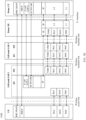
- an upper protocol layer of an RLC layer may include any one of the following: a packet data convergence protocol PDCP layer, an adaptation Adapt layer, or an F1 interface protocol layer.
- the first PDCP layer entity and the M th PDCP layer entity in Table 1 may be a same PDCP layer entity.
- the IAB node includes only one PDCP layer entity.
- the first PDCP layer entity and the M th PDCP layer entity in Table 1 may be different PDCP layer entities.
- the IAB node includes a plurality of PDCP layer entities.
- the first Adapt layer entity and the M th Adapt layer entity in Table 1 may be a same Adapt layer entity.
- the IAB node includes only one Adapt layer entity.
- the first Adapt layer entity and the M th Adapt layer entity in Table 1 may be different Adapt layer entities.
- the IAB node includes a plurality of Adapt layer entities.
- the first F1 interface protocol layer entity and the M th F1 interface protocol layer entity in Table 1 may be a same F1 interface protocol layer entity.
- the IAB node includes only one F1 interface protocol layer entity.
- the first F1 interface protocol layer entity and the M th F1 interface protocol layer entity in Table 1 may be different F1 interface protocol layer entities.
- the IAB node includes a plurality of F1 interface protocol layer entities.
- Table 1 shows only a possible correspondence between the RLC layer entity and the upper protocol layer entity of the RLC layer.
- the correspondence is not limited to the form shown in Table 1.
- the third indication information may indicate the correspondence in a form of a bit string (bit string), a sequence (sequence), or a bitmap (bit map). For example, "0000" is used to indicate the first row in Table 1, ..., "0111” is used to indicate the eighth row in Table 1, and so on.
- example beneficial effects include: In this way, content included in the third indication information can be flexibly configured, or signaling overheads can be controlled.
- Operation 202 The first node delivers the data to the upper protocol layer of the RLC layer of the first node based on the indication information.
- the MAC header of the data packet may include the first indication information, and the first indication information includes the LCID.
- the first node delivers the data to the upper protocol layer of the RLC layer based on the LCID and a correspondence between the LCID and the upper protocol layer of the RLC layer.
- the LCID corresponds to an F1 interface protocol layer of a DU of the first node
- the data needs to be delivered to the F1 interface protocol layer of the DU of the first node.
- the LCID corresponds to a PDCP layer of an MT of the first node
- the data needs to be delivered to the PDCP layer of the MT of the first node.
- the LCID corresponds to an Adapt layer of a DU of the first node
- the data needs to be delivered to the Adapt layer of the DU of the first node.
- the LCID corresponds to an Adapt layer of an MT of the first node
- the data needs to be delivered to the Adapt layer of the MT of the first node.
- the information includes information about a first group of LCIDs and/or information about a second group of LCIDs, the first group of LCIDs includes an LCID used for the access traffic, and the second group of LCIDs includes an LCID used for the backhaul traffic.
- the LCID belongs to the first group of LCIDs, and the data packet received by the first node is an uplink data packet, the LCID corresponds to the F1 interface protocol layer of the DU of the first node.
- the LCID belongs to the first group of LCIDs, and the data packet received by the first node is a downlink data packet, the LCID corresponds to the PDCP layer of the MT of the first node.
- the LCID belongs to the second group of LCIDs, and the data packet received by the first node is an uplink data packet, the LCID corresponds to the Adapt layer of the DU of the first node.
- the LCID belongs to the second group of LCIDs, and the data packet received by the first node is a downlink data packet, the LCID corresponds to the Adapt layer of the MT of the first node.
- the information is RLC bearer configuration information that is of the first node and that is used to set up a logical channel, and an RLC bearer includes a logical channel indicated by the LCID. If the information includes a radio bearer identifier, and the data packet received by the first node is an uplink data packet, the LCID corresponds to the F1 interface protocol layer of the DU of the first node. Alternatively, if the information includes a radio bearer identifier, and the data packet received by the first node is a downlink data packet, the LCID corresponds to the PDCP layer of the MT of the first node.
- the LCID corresponds to the Adapt layer of the DU of the first node.
- the LCID corresponds to the Adapt layer of the MT of the first node.
- the information is RLC bearer configuration information that is of the first node and that is used to set up a logical channel
- an RLC bearer includes a logical channel indicated by the LCID
- the information includes indication information
- values of the indication information include a first value and a second value. If the value of the indication information is the first value, and the data packet received by the first node is an uplink data packet, the LCID corresponds to the F1 interface protocol layer of the DU of the first node. Alternatively, if the value of the indication information is the first value, and the data packet received by the first node is a downlink data packet, the LCID corresponds to the PDCP layer of the MT of the first node.
- the LCID corresponds to the Adapt layer of the DU of the first node.
- the LCID corresponds to the Adapt layer of the MT of the first node.
- the indication information may be in a form of a bitmap (bitmap) or a sequence (sequence).
- bitmap bitmap
- sequence sequence
- the first value is 010
- the second value is 101.
- the RLC header of the data packet may include the second indication information. If the second indication information includes the indication information of the access traffic, and the data packet received by the first node is an uplink data packet, the data needs to be delivered to the F1 interface protocol layer of the DU of the first node. Alternatively, if the second indication information includes the indication information of the access traffic, and the data packet received by the first node is a downlink data packet, the data needs to be delivered to the PDCP layer of the MT of the first node. If the second indication information includes the indication information of the backhaul traffic, and the data packet received by the first node is an uplink data packet, the data needs to be delivered to the Adapt layer of the DU of the first node.
- values of the second indication information may include a first value and a second value. If the value of the indication information is the first value, the second indication information indicates the access traffic. If the value of the second indication information is the second value, the second indication information indicates the backhaul traffic.
- the second indication information may be in a form of a bitmap (bitmap) or a sequence (sequence). For example, the first value is 010, and the second value is 101.
- the first node receives the third indication information, and the first node configures the correspondence between the RLC layer entity and the upper protocol layer entity of the RLC layer of the first node based on the third indication information.
- the first node receives the data by using the RLC layer entity. If the third indication information indicates that the RLC layer entity corresponds to a PDCP layer entity or an F1 interface protocol layer entity, the first node delivers the data to the PDCP layer or the F1 interface protocol layer of the first node. If the third indication information indicates that the RLC layer entity corresponds to an Adapt layer entity, the first node delivers the data to the Adapt layer of the first node.
- the F1 interface protocol layer is also referred to as the upper protocol layer of the RLC layer in this application, and a channel between the RLC layer and the F1 interface protocol layer is also referred to as an RLC channel in this application.
- the operation 202 is correspondingly modified to be that the first node delivers the data to the upper protocol layer of the RLC layer or the F1 interface protocol layer of the first node based on the first indication information or the second indication information.
- a corresponding part in this embodiment also needs to be modified accordingly, and details are not described herein again.
- a type of the data may be classified based on an RLC channel from which the data comes or the channel between the RLC layer and the F1 interface protocol layer.
- a corresponding part in this embodiment also needs to be modified accordingly, and details are not described herein again.
- an RLC layer entity of the MT of the IAB node is classified into two types: One type is configured to transmit a backhaul traffic (namely, a backhaul traffic), and associates an adaptation layer entity with an upper layer. The other type is used to transmit an MT access traffic (namely, an access traffic), and associate a PDCP layer entity with an upper layer.
- that the RLC layer entity associates an X layer entity with the upper layer means that an upper protocol layer of an RLC layer is an X layer.
- an RLC layer of the MT of the IAB node when configured, for example, an RRC message sent by a donor node to the MT includes a cell group-related configuration (CellGroupConfig) information element, and the information element includes a part related to the configuration of the RLC bearer.
- CellGroupConfig cell group-related configuration
- indication information may be included in an information element (for example, RLC-BearerConfig) used to configure the RLC bearer, to indicate whether the upper layer of the RLC layer entity is associated with the PDCP entity or the Adapt entity.
- the information element for example, the RLC-BearerConfig
- the donor node includes the information element in the RRC message sent to the MT of the IAB node.
- the indication information may be explicitly carried in a message for configuring the RLC bearer.
- the RLC-BearerConfig information element sent to the MT of the IAB node includes an indication information element, and the indication information element has two values (for example, 0 and 1).
- the value 1 indicates that the RLC layer entity associates the Adapt entity with the upper layer
- the value 2 indicates that the RLC layer entity associates the PDCP entity with the upper layer.
- the indication information may be implicitly carried.
- the RLC-BearerConfig information element carries a radio bearer identifier (for example, a data radio bearer identifier DRB ID or a signaling radio bearer identifier SRB ID).
- a radio bearer identifier for example, a data radio bearer identifier DRB ID or a signaling radio bearer identifier SRB ID.
- the RLC-BearerConfig information element used to configure the RLC layer entity does not carry a radio bearer identifier. Therefore, when a logical channel of an RLC bearer is set up, whether the logical channel includes a radio bearer identifier may indicate whether the RLC bearer is used to carry the MT access traffic (where the RLC layer entity corresponding to the RLC bearer associates the PDCP layer entity with the upper layer) or the backhaul traffic (where the RLC layer entity corresponding to the RLC bearer associates the Adapt layer entity with the upper layer).
- an LCID of a logical channel corresponding to the RLC bearer may be used to implicitly indicate that the RLC bearer is used to carry the MT access traffic or is used to carry the backhaul traffic. That is, if the LCID falls within an LCID value range corresponding to the MT access traffic, it indicates that the RLC bearer is used to carry the MT access traffic (where the RLC layer entity corresponding to the RLC bearer associates the PDCP layer entity with the upper layer).
- the LCID falls within an LCID value range corresponding to the backhaul traffic, it indicates that the RLC bearer is used to carry the backhaul traffic (where the RLC layer entity corresponding to the RLC bearer associates the Adapt layer entity with the upper layer). This manner depends on that a pre-divided LCID range corresponds to the backhaul (backhaul) traffic or the access traffic (MT access traffic) of the IAB node. For details, refer to descriptions in the following paragraph.
- the DU of the parent node of the IAB node configures a plurality of logical channels for a wireless link between the IAB node and the parent node, and allocates a corresponding logical channel identity LCID to each logical channel.
- a relatively simple manner is that when the DU of the parent node allocates the logical channel identity to the MT of the IAB node, an LCID value range (LCID space) is divided, a part obtained through the division is used to serve the MT access traffic of the IAB node, and the other part is used to serve the backhaul traffic of the IAB node.
- the LCID value range (converted into decimal) of the IAB node on a backhaul link is [0, 63]
- a part of LCIDs in a range of [0, 7] are obtained through division and allocated to a logical channel used to serve the MT access traffic, and a remaining part of LCIDs in a range of [8, 63] are allocated to a logical channel used to serve the backhaul traffic.
- a specific division manner of the LCID value range may directly use a fixed division manner.
- the donor node may further notify the division manner to the MT of the IAB node by using an RRC message, or notify the division manner to the DU of the parent node of the IAB node by using an F1AP message.
- a donor node may send configuration information to the IAB node, to indicate the IAB node to set up an RLC bearer between the IAB node and a child node of the IAB node, and include indication information in the configuration information, to indicate whether the RLC bearer is used to serve a backhaul traffic or an access traffic of the child node.
- the configuration information is an F1AP message sent by the donor node to the DU of the IAB node.
- a MAC header in the downlink data packet includes first indication information, namely, a logical channel identity LCID included in the data packet.
- the IAB 2 receives configuration information that is of an RLC bearer of the MT from a donor node and that includes the LCID, and the IAB determines, based on the configuration information, whether the RLC bearer is used for an access traffic or a backhaul traffic. If the RLC bearer is used for the access traffic, an RLC layer entity of the RLC bearer associates a PDCP layer entity with an upper layer.
- the IAB 2 may determine, based on the LCID included in the data packet, whether the RLC bearer for receiving the downlink data packet is used for the access traffic or the backhaul traffic. If it is determined that the RLC bearer of the IAB 2 is an RLC bearer used for the access traffic, the IAB 2 delivers data to a PDCP layer. If it is determined that the RLC bearer of the IAB 2 is an RLC bearer used for the backhaul traffic, the IAB 2 delivers data to an Adapt layer.
- a MAC header in the uplink data packet includes first indication information, namely, a logical channel identity LCID included in the data packet.
- the IAB 2 may determine, based on the LCID, a corresponding RLC bearer for receiving the uplink data packet and an RLC layer entity corresponding to the RLC bearer.
- the IAB 2 determines, based on configuration information of the RLC bearer previously sent by the donor node, whether the RLC bearer for receiving the uplink data packet is used for the access traffic or the backhaul traffic. If it is determined that the RLC bearer is an RLC bearer for the access traffic, the IAB 2 delivers data to an F1 interface protocol layer. If it is determined that the RLC bearer is an RLC bearer for the backhaul traffic, the IAB 2 delivers data to an Adapt layer.
- the IAB 2 For downlink transmission, when the RLC layer entity of the MT of the IAB 2 receives a downlink data packet, if second indication information in an RLC header of the downlink data packet indicates that data is the access traffic, the IAB 2 delivers the data to the PDCP layer, or if second indication information indicates that data is the backhaul traffic, the IAB 2 delivers the data to the Adapt layer.
- the IAB 2 For uplink transmission, when the RLC layer entity of the DU of the IAB 2 receives an uplink data packet, if second indication information in an RLC header of the uplink data packet indicates that data is the access traffic, the IAB 2 delivers the data to the F1 interface layer, or if second indication information indicates that data is the backhaul traffic, the IAB 2 delivers the data to the Adapt layer.
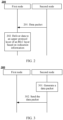
- FIG. 3 is a schematic flowchart of a communication method according to this application. The following specifically describes the technical solutions in the embodiments of this application with reference to FIG. 3 .
- the communication method 300 corresponding to FIG. 3 may include the following steps.
- Operation 301 A second node generates a data packet.
- the data packet may include data and a protocol layer header
- the data may be an actual payload of data transmission between nodes.
- the actual payload of the data transmission between the nodes may be understood as meaningful information other than the protocol layer header from the data packet.
- the protocol layer header may include a media access control MAC header.
- the MAC header includes first indication information, and the first indication information includes a logical channel identity (logical channel identity, LCID) corresponding to the data packet.
- LCID logical channel identity
- the LCID is used to identify a logical channel between an RLC layer and a MAC layer
- the LCID and the logical channel may be in a one-to-one correspondence
- the LCID corresponding to the data packet is an LCID of a logical channel that corresponds to a channel from which the data comes and that is added by the second node to the data packet based on the channel from which the data comes, where the channel is a logical channel.
- the channel may be an RLC channel between an RLC layer and an upper protocol layer.
- the RLC channel may be a channel between an RLC layer and a PDCP layer, or the RLC channel may be a channel between an RLC layer and an Adapt layer.
- the channel may be a channel between an RLC layer and an F1 interface protocol layer.
- the second node adds, to the data packet, the LCID of the logical channel corresponding to the data packet includes:
- the second node receives information from a donor node, and the second node obtains a correspondence between the RLC channel and the LCID based on the information.
- the second node stores the information, and the second node obtains the correspondence between the RLC channel and the LCID based on the information.
- content included in the information may alternatively be specified in a protocol or a standard, and the second node device stores the information before delivery.
- the information includes information about a first group of LCIDs and/or information about a second group of LCIDs, the first group of LCIDs includes an LCID used for an access traffic, and the second group of LCIDs includes an LCID used for a backhaul traffic.
- a parent node of the second node for example, a DU of the parent node, configures a plurality of logical channels for a wireless link between the second node and the parent node, and allocates a corresponding logical channel identity LCID to each logical channel.
- an LCID value range (converted into decimal) is [0, X]
- the parent node may determine an LCID used for the access traffic of the second node within a part, for example, a range of [0, Y], that belongs to the first group of LCIDs in the LCID value range (LCID space), and allocate the LCID to a logical channel used to serve the access traffic of the second node; or the parent node may determine an LCID used for the backhaul traffic of the second node within a part, for example, a range of [Y, Z], that belongs to the second group of LCIDs in the LCID value range, and allocate the LCID to a logical channel used to serve the backhaul traffic of the second node, where X, Y, and Z are all positive integers, Y ⁇ Z, and Z ⁇ X.
- the second node for example, a DU of the second node, configures a plurality of logical channels for a wireless link between the second node and a child node, and allocates a corresponding logical channel identity LCID to each logical channel.
- an LCID value range (converted into decimal) is [0, X]
- the second node may determine an LCID used for the access traffic of the child node within a part, for example, a range of [0, Y], that belongs to the first group of LCIDs in the LCID value range (LCID space), and allocate the LCID to a logical channel used to serve the access traffic of the child node; or the second node may determine an LCID used for the backhaul traffic of the second node within a part, for example, a range of [Y, Z], that belongs to the second group of LCIDs in the LCID value range, and allocate the LCID to a logical channel used to serve the backhaul traffic of the child node, where X, Y, and Z are all positive integers, Y ⁇ Z, and Z ⁇ X.
- the second node determines, in the first group of LCIDs, an LCID corresponding to the RLC channel. Specifically, after receiving RLC bearer configuration information, the second node may determine whether an LCID in the RLC bearer configuration information belongs to the first group of LCIDs or the second group of LCIDs. If the LCID belongs to the first group of LCIDs, the second node determines that the LCID corresponds to the channel between the RLC layer and the PDCP layer or the F1 interface protocol layer.
- the second node determines, in the second group of LCIDs, an LCID corresponding to the data packet. Specifically, after receiving RLC bearer configuration information, the second node may determine whether an LCID in the RLC bearer configuration information belongs to the first group of LCIDs or the second group of LCIDs. If the LCID belongs to the second group of LCIDs, the second node determines that the LCID corresponds to the channel between the RLC layer and the Adapt layer.
- the information is RLC bearer configuration information that is of a first node and that is used to set up a logical channel, and the RLC bearer includes the logical channel indicated by the LCID. If the information includes a radio bearer identifier, and the data packet sent by the second node is a downlink data packet, the LCID corresponds to the channel between the RLC layer and the F1 interface protocol layer of the DU of the second node. Alternatively, if the information includes a radio bearer identifier, and the data packet sent by the second node is an uplink data packet, the LCID corresponds to the channel between the RLC layer and the PDCP layer of the MT of the second node.
- the LCID corresponds to the channel between the RLC layer and the Adapt layer of the DU of the second node.
- the LCID corresponds to the channel between the RLC layer and the Adapt layer of the MT of the second node.
- the information is RLC bearer configuration information that is of the first node and that is used to set up a logical channel
- an RLC bearer includes a logical channel indicated by the LCID
- the information includes indication information
- values of the indication information include a first value and a second value. If the value of the indication information is the first value, and the data packet sent by the second node is a downlink data packet, the LCID corresponds to a channel between an RLC layer and an F1 interface protocol layer of a DU of the second node.
- the LCID corresponds to a channel between an RLC layer and a PDCP layer of an MT of the second node. If the value of the indication information is the second value, and the data packet sent by the second node is a downlink data packet, the LCID corresponds to a channel between an RLC layer and an Adapt layer of a DU of the second node. Alternatively, if the value of the indication information is the second value, and the data packet sent by the second node is an uplink data packet, the LCID corresponds to a channel between an RLC layer and an Adapt layer of an MT of the second node.
- the indication information may be in a form of a bitmap (bitmap) or a sequence (sequence). For example, the first value is 010, and the second value is 101.
- the protocol layer header may include a radio link control RLC header.
- the RLC header includes second indication information, and the second indication information includes indication information of an access traffic or indication information of a backhaul traffic.
- the second node receives the data through an RLC channel. If the RLC channel is a channel between the RLC layer and the PDCP layer or the F1 interface protocol layer, the second node determines that the second indication information is the indication information of the access traffic; or if the RLC channel is a channel between the RLC layer and the Adapt layer, the second node determines that the second indication information is the indication information of the backhaul traffic.
- the second node may determine, based on routing information in an Adapt PDU received by an adaptation layer entity, whether the current node is a target node of a route of the adaptation layer. If it is determined that the current node is the target node of the route of the adaptation layer, the second node determines that the second indication information is the indication information of the access traffic. If it is determined that the current node is not the target node of the route of the adaptation layer, the second node determines that the second indication information is the indication information of the backhaul traffic.
- Operation 302 The second node sends the data packet to the first node.
- the second node sends the data packet to the first node, where the data packet includes indication information that is of a type of the traffic data and that is determined by using the operation 301.
- the second node is a donor node, and the second node sends third indication information to the first node, where the third indication information indicates a correspondence between an RLC layer entity and an upper protocol layer entity of the RLC layer of the first node.
- the operation 301 is an optional operation.
- an IAB node processes a data packet in combination with the protocol stack structures of the IAB network shown in FIG. 1B and FIG. 1C .
- the DU of the IAB 2 may determine, based on an RLC bearer that is of the IAB 2 and that is used to receive data, whether the data is an access traffic or a backhaul traffic. If the IAB 2 determines, based on RLC bearer configuration information and/or LCID grouping information previously received from the donor node, that the RLC bearer is an RLC bearer used for the access traffic, an RLC layer of the DU of the IAB 2 may add first indication information to a MAC header of a data packet including the data, where the first indication information includes an LCID of a logical channel included in the RLC bearer.
- an RLC layer of the DU of the IAB 2 may add first indication information to a MAC header of a data packet including the data, where the first indication information includes an LCID of a logical channel included in the RLC bearer.
- the MT of the IAB 2 may determine, based on an RLC bearer that is of the IAB 2 and that is used to receive data, whether the data is an access traffic or a backhaul traffic. If the IAB 2 determines, based on RLC bearer configuration information and/or LCID grouping information previously received from the donor node, that the RLC bearer is an RLC bearer used for the access traffic, an RLC layer of the DU of the IAB 2 may add first indication information to a MAC header of a data packet including the data, where the first indication information includes an LCID of a logical channel included in the RLC bearer.
- an RLC layer of the DU of the IAB 2 may determine, based on an upper protocol layer of the RLC layer from which the data received by the RLC layer comes, whether the data is an access traffic or a backhaul traffic. For example, if an RLC SDU that includes the data and that is received by the RLC layer of the DU of the IAB 2 is a PDCP PDU, the upper protocol layer of the RLC layer from which the data received by the RLC layer comes may be the F1 interface protocol layer, the data may be determined as the access traffic, and the RLC layer of the DU of the IAB 2 may add second indication information to an RLC header of a data packet that includes the data, where the second indication indicates that the data is the access traffic.
- an RLC SDU that includes the data and that is received by the RLC layer of the DU of the IAB 2 is an Adapt PDU
- the upper protocol layer of the RLC layer from which the data received by the RLC layer comes may be the Adapt layer
- the data may be determined as the backhaul traffic
- the RLC layer of the DU of the IAB 2 may add second indication information to a MAC header of a data packet that includes the data, where the second indication information indicates that the data is the backhaul traffic.
- an RLC layer of the MT of the IAB 2 may determine, based on an upper protocol layer of the RLC layer from which the data received by the RLC layer comes, whether the data is an access traffic or a backhaul traffic. For example, if an RLC SDU that includes the data and that is received by the RLC layer of the DU of the IAB 2 is a PDCP PDU, the upper protocol layer of the RLC layer from which the data received by the RLC layer comes may be the PDCP layer, the data may be determined as the access traffic, and the RLC layer of the DU of the IAB 2 may add second indication information to an RLC header of a data packet that includes the data, where the second indication indicates that the data is the access traffic.
- an RLC SDU that includes the data and that is received by the RLC layer of the DU of the IAB 2 is an Adapt PDU
- the upper protocol layer of the RLC layer from which the data received by the RLC layer comes may be the Adapt layer
- the data may be determined as the backhaul traffic
- the RLC layer of the DU of the IAB 2 may add second indication information to a MAC header of a data packet that includes the data, where the second indication information indicates that the data is the backhaul traffic.
- the communication apparatus includes: at least one corresponding unit configured to perform a method step, an operation, or an action performed by the communication device in the communication method/system provided in the method 200 or 300.
- the at least one unit may be configured in a one-to-one correspondence with the method step, the operation, or the action performed by the communication apparatus.
- These units may be implemented by using a computer program, may be implemented by using a hardware circuit, or may be implemented by using a computer program in combination with a hardware circuit.
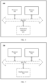
- FIG. 4 is a schematic block diagram of the communication apparatus 400 according to an embodiment of this application.
- this application provides a first node 400, including: an obtaining module 401, configured to receive a data packet from a second node, where the data packet includes data and a media access control MAC header, the MAC header includes first indication information, and the first indication information includes a logical channel identity LCID corresponding to the data packet, or the data packet includes data and a radio link control RLC header, the RLC header includes second indication information, and the second indication information includes indication information of an access traffic or indication information of a backhaul traffic; or the obtaining module 401 is configured to receive third indication information, where the third indication information indicates a correspondence between an RLC layer entity and an upper protocol layer entity of an RLC layer of the first node 400; and a processing module 402, configured to deliver the data to an upper protocol layer of the RLC layer of the first node 400 based on the first indication information or the second indication information, where the first node 400 and the second node are nodes in wireless relay communication, and an upper protocol layer of an RLC layer includes any one of the following
- the obtaining module 401 may be further configured to receive information from a donor node, and the processing module 402 may be further configured to obtain the correspondence between the LCID and the upper protocol layer of the RLC layer based on the information.
- the processing module 402 obtains the correspondence between the LCID and the upper protocol layer of the RLC layer based on the information includes:
- the information includes information about a first group of LCIDs and/or information about a second group of LCIDs, the first group of LCIDs includes an LCID used for the access traffic, and the second group of LCIDs includes an LCID used for the backhaul traffic; and if the LCID belongs to the first group of LCIDs, the upper protocol layer of the RLC layer is the PDCP layer or the F1 interface protocol layer; or if the LCID belongs to the second group of LCIDs, the upper protocol layer of the RLC layer is the Adapt layer.
- the information is used to configure an RLC bearer of the first node 400, where the RLC bearer includes a logical channel indicated by the LCID; and if the information includes a radio bearer identifier, the upper protocol layer of the RLC layer is the PDCP layer or the F1 interface protocol layer; or if the information does not include a radio bearer identifier, the upper protocol layer of the RLC layer is the Adapt layer.
- the information is used to configure an RLC bearer of the first node 400, where the RLC bearer includes a logical channel indicated by the LCID; the information includes indication information, and values of the indication information include a first value and a second value; and if the value of the indication information is the first value, the upper protocol layer of the RLC layer is the PDCP layer or the F1 interface protocol layer; or if the value of the indication information is the second value, the upper protocol layer of the RLC layer is the Adapt layer.
- the F1 interface protocol layer is a protocol layer on a logical interface between a centralized unit CU of the donor node and a distributed unit DU of the node;
- a user plane of the F1 interface protocol layer includes a GPRS tunneling protocol-user plane GTP-U layer, a user datagram protocol UDP layer, and an internet protocol IP layer;
- a control plane of the F1 interface protocol layer includes an F1 interface application F1AP layer, a stream control transmission protocol SCTP layer, and an internet protocol IP layer.
- the apparatus may be a communication apparatus in the communication method/system provided in any one of the method 200 or the method 300 and the possible designs thereof in the foregoing embodiments.
- the communication apparatus includes: at least one corresponding unit configured to perform a method step, an operation, or an action performed by the communication device in the communication method/system provided in the method 200 or 300.
- the at least one unit may be configured in a one-to-one correspondence with the method step, the operation, or the action performed by the communication apparatus.
- These units may be implemented by using a computer program, may be implemented by using a hardware circuit, or may be implemented by using a computer program in combination with a hardware circuit.
- FIG. 5 is a schematic block diagram of the communication apparatus 500 according to an embodiment of this application.
- this application provides a second node 500, including: a sending module 502, configured to send a data packet to a first node; or the sending module 502 is configured to send third indication information to the first node, where the third indication information indicates a correspondence between an RLC layer entity and an upper protocol layer entity of an RLC layer of the first node 400.
- processing module 501 determines the LCID corresponding to the data packet includes: The processing module 501 receives the data through an RLC channel, and the processing module 501 determines the LCID corresponding to the RLC channel.
- the processing module 501 may be further configured to receive information from a donor node, and the processing module 501 obtains a correspondence between the RLC channel and the LCID based on the information.
- the processing module 501 obtains a correspondence between the RLC channel and the LCID based on the information includes: The information is used to configure an RLC bearer of the second node, where the RLC bearer includes a logical channel indicated by the LCID; and if the information includes a radio bearer identifier, the RLC channel corresponding to the LCID is a channel between the RLC layer and the PDCP layer or the F1 interface protocol layer; or if the information does not include a radio bearer identifier, the RLC channel corresponding to the LCID is a channel between the RLC layer and the Adapt layer.
- the information includes information about a first group of LCIDs and/or information about a second group of LCIDs, the first group of LCIDs are LCIDs used for the access traffic, and the second group of LCIDs are LCIDs used for the backhaul traffic; and if the RLC channel is a channel between the RLC layer and the PDCP layer or the F1 interface protocol layer, the processing module 501 determines, in the first group of LCIDs, the LCID corresponding to the RLC channel; or if the RLC channel is a channel between the RLC layer and the Adapt layer, the processing module 501 determines, in the second group of LCIDs, the LCID corresponding to the data packet.
- the information is used to configure an RLC bearer of the second node 500, where the RLC bearer includes a logical channel indicated by the LCID; the information includes indication information, and values of the indication information include a first value and a second value; and if the value of the indication information is the first value, the RLC channel corresponding to the LCID is a channel between the RLC layer and the PDCP layer or the F1 interface protocol layer; or if the value of the indication information is the second value, the RLC channel corresponding to the LCID is a channel between the RLC layer and the Adapt layer.
- the F1 interface protocol layer is a protocol layer on a logical interface between a centralized unit CU of the donor node and a distributed unit DU of the node;
- a user plane of the F1 interface protocol layer includes a GPRS tunneling protocol-user plane GTP-U layer, a user datagram protocol UDP layer, and an internet protocol IP layer;
- a control plane of the F1 interface protocol layer includes an F1 interface application F1AP layer, a stream control transmission protocol SCTP layer, and an internet protocol IP layer.
- this application provides a donor node 500, including: a sending module 502, where the sending module 502 is configured to send information to a first node, where the information includes information about a first group of LCIDs and/or information about a second group of LCIDs, the first group of LCIDs includes an LCID used for an access traffic, and the second group of LCIDs includes an LCID used for a backhaul traffic; or the information is used to configure an RLC bearer of the first node, where the RLC bearer includes an RLC layer entity and a logical channel, and if the information includes a radio bearer identifier, an upper protocol layer of an RLC layer is a PDCP layer or an F1 interface protocol layer; or if the information does not include a radio bearer identifier, an upper protocol layer of an RLC layer is an Adapt layer; or the information is used to configure an RLC bearer of the first node, where the RLC bearer includes an RLC layer entity and a logical channel
- an embodiment of this application further provides a communication apparatus.
- the communication apparatus may be configured to implement a function performed by any terminal device or any radio access network device in the foregoing method embodiments.
- the following specifically describes a structure and a function of a communication apparatus 600 with reference to FIG. 6 in the embodiments of this application.
- FIG. 6 is a schematic block diagram of the communication apparatus 600 according to an embodiment of this application.
- the communication apparatus may include at least one processor 601. When program instructions are executed in the at least one processor 601, a function of the terminal device or the radio access network device in any design in the communication method/system provided in the method 200 or 300 is implemented.
- the communication apparatus 600 may further include at least one memory 602, and the memory 602 may be configured to store required program instructions and/or required data.
- the communication apparatus 600 may further include a transceiver apparatus 603.
- the transceiver apparatus 603 may be used by the communication apparatus 600 to perform communication interaction with another communication device (for example, a radio access network device or a terminal device, which is not limited herein), for example, exchange control signaling and/or traffic data.
- the transceiver apparatus 603 may be implemented by using a circuit having a communication transceiver function.
- the communication apparatus 600 may further include a bus 604, and the components in the communication apparatus 600 may be interconnected through the bus 604.
- FIG. 7 is a schematic block diagram of the system chip 700 according to an embodiment of this application.
- the system chip 700 may be used in any terminal device or any radio access network device described above. Processing performed by the system chip enables the terminal device or the radio access network device to perform an operation of the terminal device or the radio access network device in any possible design solution of the communication method/system provided in the methods 300 to 500 in the embodiments of this application.
- the system chip 700 may include at least one processor 701.
- the system chip 700 may further include at least one memory 702, and the memory 702 stores the related program instructions.
- the system chip 700 may further include an interface circuit 703 and a bus 704.
- the at least one processor 701, the at least one memory 702, and the interface circuit 703 are coupled through the bus 704.
- the system chip 700 interacts with a terminal device, a radio access network device, or another device in a network through the interface circuit 703.
- the processor 701 and the memory 702 may be combined into one processing apparatus.
- the memory 702 may alternatively be integrated into the processor 701, or may be independent of the processor 701.
- the disclosed system, apparatus, and method may be implemented in other manners.
- the described apparatus embodiment is merely an example.
- the module or unit division is merely logical function division and may be other division in actual implementations.
- a plurality of units or components may be combined or integrated into another system, or some features may be ignored or not performed.
- the displayed or discussed mutual couplings or direct couplings or communication connections may be implemented through some interfaces.
- the indirect couplings or communication connections between the apparatuses or units may be implemented in electrical, mechanical, or other forms.
- the processor in the embodiments of this application may be a central processing unit (central processing unit, CPU), or the processor may be another general purpose processor, a digital signal processor (digital signal processor, DSP), an application-specific integrated circuit (application specific integrated circuit, ASIC), a field programmable gate array (field programmable gate array, FPGA) or another programmable logic device, a discrete gate or a transistor logic device, a discrete hardware component, or the like.
- the general purpose processor may be a microprocessor, any conventional processor, or the like.
- the memory in the embodiments of this application may be a volatile memory or a non-volatile memory, or may include a volatile memory and a non-volatile memory.
- the nonvolatile memory may be a read-only memory (read-only memory, ROM), a programmable read-only memory (programmable ROM, PROM), an erasable programmable read-only memory (erasable PROM, EPROM), an electrically erasable programmable read-only memory (electrically EPROM, EEPROM), or a flash memory.
- the volatile memory may be a random access memory (random access memory, RAM), and is used as an external cache.
- random access memory random access memory
- static random access memory static random access memory
- DRAM dynamic random access memory
- DRAM dynamic random access memory
- SDRAM synchronous dynamic random access memory
- double data rate synchronous dynamic random access memory double data rate SDRAM, DDR SDRAM
- ESDRAM enhanced synchronous dynamic random access memory
- synchlink dynamic random access memory synchlink DRAM, SLDRAM
- direct rambus RAM direct rambus RAM, DR RAM
- the units described as separate components may or may not be physically separate, and components displayed as units may or may not be physical units, may be located in one position, or may be distributed on a plurality of network units. Some or all of the units may be selected based on actual requirements to achieve the objectives of the solutions in the embodiments of this application.
- function units in the embodiments of this application may be integrated into one processing unit, or each of the units may exist alone physically, or two or more units may be integrated into one unit.
- the integrated unit may be implemented in a form of hardware, or may be implemented in a form of a software function unit.
- the integrated unit When the integrated unit is implemented in the form of the software function unit and sold or used as an independent product, the integrated unit may be stored in a computer-readable storage medium. Based on such an understanding, the technical solutions of this application essentially, or the part contributing to the current technology, or all or some of the technical solutions may be implemented in a form of a software product.
- the computer software product is stored in a storage medium and includes several instructions for instructing a computer device (which may be a personal computer, a server, a radio access network device, or the like) or a processor (processor) to perform all or some of the operations of the methods in the embodiments of this application.
- the foregoing storage medium may include any medium or computer storage medium that can store program code, such as a USB flash drive, a removable hard disk, a read-only memory (read-only memory, ROM), a random access memory (random access memory, RAM), a magnetic disk, or an optical disc.
- program code such as a USB flash drive, a removable hard disk, a read-only memory (read-only memory, ROM), a random access memory (random access memory, RAM), a magnetic disk, or an optical disc.
Landscapes
- Engineering & Computer Science (AREA)
- Signal Processing (AREA)
- Computer Networks & Wireless Communication (AREA)
- Computer Security & Cryptography (AREA)
- Mobile Radio Communication Systems (AREA)
Claims (10)
- Kommunikationsverfahren (200), umfassend:Empfangen (201), durch einen ersten Knoten, eines Datenpakets von einem zweiten Knoten, wobei das Datenpaket Daten und einen Media-Access-Control-Header, MAC-Header, umfasst, der MAC-Header erste Anzeigeinformationen umfasst und die ersten Anzeigeinformationen eine logische Kanalidentität, LCID, umfassen, die dem Datenpaket entspricht; undLiefern (202), durch den ersten Knoten, der Daten an eine obere Protokollschicht einer Funkverbindungssteuerungsschicht, RLC-Schicht, des ersten Knotens basierend auf den ersten Anzeigeinformationen, wobei das Liefern, durch den ersten Knoten, der Daten an eine obere Protokollschicht der RLC-Schicht des ersten Knotens basierend auf den ersten Anzeigeinformationen Liefern, durch den ersten Knoten, der Daten an die obere Protokollschicht der RLC-Schicht basierend auf der LCID und einer Entsprechung zwischen der LCID und der oberen Protokollschicht der RLC-Schicht umfasst, wobeider erste Knoten und der zweite Knoten Knoten in einer drahtlosen Relaiskommunikation in einem integrierten Zugriffs- und Backhaul-Netzwerk, IAB-Netzwerk, sind und eine obere Protokollschicht einer RLC-Schicht beliebige der Folgenden umfasst: eine Paketdatenkonvergenzprotokollschicht, PDCP-Schicht, eine Anpassungsschicht, Adapt-Schicht, oder eine F1-Schnittstellenprotokollschicht.
- Verfahren (200) nach Anspruch 1, wobei das Verfahren ferner Folgendes umfasst:
Empfangen, durch den ersten Knoten, von Informationen von einem Geberknoten und Erlangen, durch den ersten Knoten, der Entsprechung zwischen der LCID und der oberen Protokollschicht der RLC-Schicht basierend auf den Informationen. - Verfahren (200) nach Anspruch 2, wobei das Verfahren ferner Folgendes umfasst:die Informationen umfassen mindestens eines aus Informationen über eine erste Gruppe von LCIDs oder Informationen über eine zweite Gruppe von LCIDs, wobei die erste Gruppe von LCIDs eine LCID umfasst, die für Zugriffsverkehr verwendet wird, und die zweite Gruppe von LCIDs eine LCID umfasst, die für Backhaul-Verkehr verwendet wird; undwenn die LCID zu der ersten Gruppe von LCIDs gehört, ist die obere Protokollschicht der RLC-Schicht die PDCP-Schicht oder die F1-Schnittstellenprotokollschicht; oderwenn die LCID zu der zweiten Gruppe von LCIDs gehört, ist die obere Protokollschicht der RLC-Schicht die Adapt-Schicht.
- Verfahren (200) nach Anspruch 2, wobei das Verfahren ferner Folgendes umfasst:die Informationen werden verwendet, um einen RLC-Träger des ersten Knotens zu konfigurieren, wobei der RLC-Träger einen logischen Kanal umfasst, der durch die LCID angezeigt wird; undwenn die Informationen eine Funkträgerkennung umfassen, ist die obere Protokollschicht der RLC-Schicht die PDCP-Schicht oder die F1-Schnittstellenprotokollschicht; oderwenn die Informationen keine Funkträgerkennung umfassen, ist die obere Protokollschicht der RLC-Schicht die Adapt-Schicht.
- Kommunikationsverfahren (300), umfassend:Empfangen, durch einen zweiten Knoten, von Informationen von einem Geberknoten und Erlangen, durch den zweiten Knoten, einer Entsprechung zwischen einem RLC-Kanal und der LCID basierend auf den Informationen, wobei der RLC-Kanal ein Kanal zwischen der RLC-Schicht und einer oberen Protokollschicht der RLC-Schicht ist,Senden (302), durch den zweiten Knoten, eines Datenpakets an einen ersten Knoten, wobei das Datenpaket Daten und einen Media-Access-Control-Header, MAC-Header, umfasst, der MAC-Header erste Anzeigeinformationen umfasst und die ersten Anzeigeinformationen eine logische Kanalidentität, LCID, umfassen, die den Daten entspricht und die durch den zweiten Knoten bestimmt wird, wobei das Bestimmen Empfangen, durch einen zweiten Knoten, der Daten über den RLC-Kanal und Bestimmen, durch den zweiten Knoten, der LCID, die dem RLC-Kanal entspricht, umfasst, wobeidie ersten Anzeigeinformationen verwendet werden, um den ersten Knoten anzuzeigen, der die Daten an eine obere Protokollschicht einer Funkverbindungssteuerungsschicht, RLC-Schicht, zu übermitteln hat; undder erste Knoten und der zweite Knoten Knoten in einer drahtlosen Relaiskommunikation in einem integrierten Zugriffs- und Backhaul-Netzwerk, IAB-Netzwerk, sind und eine obere Protokollschicht einer RLC-Schicht beliebige der Folgenden umfasst: eine Paketdatenkonvergenzprotokollschicht, PDCP-Schicht, eine Anpassungsschicht, Adapt-Schicht, oder eine F1-Schnittstellenprotokollschicht.
- Verfahren (300) nach Anspruch 5, wobei das Erlangen, durch den zweiten Knoten, einer Entsprechung zwischen dem RLC-Kanal und der LCID basierend auf den Informationen Folgendes umfasst:die Informationen werden verwendet, um einen RLC-Träger des zweiten Knotens zu konfigurieren, wobei der RLC-Träger einen logischen Kanal umfasst, der durch die LCID angezeigt wird; undwenn die Informationen eine Funkträgerkennung umfassen, ist der RLC-Kanal, welcher der LCID entspricht, ein Kanal zwischen der RLC-Schicht und der PDCP-Schicht oder der F1-Schnittstellenprotokollschicht; oderwenn die Informationen keine Funkträgerkennung umfassen, ist der RLC-Kanal, welcher der LCID entspricht, ein Kanal zwischen der RLC-Schicht und der Adapt-Schicht.
- Verfahren (300) nach Anspruch 5, wobei das Erlangen, durch den zweiten Knoten, einer Entsprechung zwischen dem RLC-Kanal und der LCID basierend auf den Informationen Folgendes umfasst:die Informationen umfassen mindestens eines aus Informationen über eine erste Gruppe von LCIDs oder Informationen über eine zweite Gruppe von LCIDs, wobei die erste Gruppe von LCIDs LCIDs sind, die für den Zugriffsverkehr verwendet werden, und die zweite Gruppe von LCIDs LCIDs sind, die für den Backhaul-Verkehr verwendet werden; undwenn der RLC-Kanal ein Kanal zwischen der RLC-Schicht und der PDCP-Schicht oder der F1-Schnittstellenprotokollschicht ist, Bestimmen, durch den zweiten Knoten in der ersten Gruppe von LCIDs, der LCID, die dem RLC-Kanal entspricht; oderwenn der RLC-Kanal ein Kanal zwischen der RLC-Schicht und der Adapt-Schicht ist, Bestimmen, durch den zweiten Knoten in der zweiten Gruppe von LCIDs, der LCID, die dem Datenpaket entspricht.
- Kommunikationsgerät (400, 500, 600), umfassend Module zum Durchführen von Schritten des Verfahrens nach einem der Ansprüche 1 bis 4, wenn das Gerät ein erster Knoten ist, oder der Schritte des Verfahrens nach einem der Ansprüche 5-7, wenn das Gerät ein zweiter Knoten ist.
- Computerprogrammprodukt, umfassend Anweisungen, die, wenn sie durch ein Gerät ausgeführt werden, das Gerät dazu veranlassen, die Schritte des Verfahrens nach einem der Ansprüche 1 bis 4 durchzuführen, wenn das Gerät in einem ersten Knoten enthalten ist, oder die Schritte des Verfahrens nach einem der Ansprüche 5-7 durchzuführen, wenn das Gerät in einem zweiten Knoten enthalten ist.
- Computerlesbares Speichermedium, umfassend das Computerprogrammprodukt nach Anspruch 9.
Applications Claiming Priority (2)
| Application Number | Priority Date | Filing Date | Title |
|---|---|---|---|
| CN201910118117.2A CN111586803B (zh) | 2019-02-15 | 2019-02-15 | 一种通信方法及相关设备 |
| PCT/CN2020/075376 WO2020164615A1 (zh) | 2019-02-15 | 2020-02-14 | 一种通信方法及相关设备 |
Publications (3)
| Publication Number | Publication Date |
|---|---|
| EP3917217A1 EP3917217A1 (de) | 2021-12-01 |
| EP3917217A4 EP3917217A4 (de) | 2022-06-29 |
| EP3917217B1 true EP3917217B1 (de) | 2025-05-21 |
Family
ID=72043965
Family Applications (1)
| Application Number | Title | Priority Date | Filing Date |
|---|---|---|---|
| EP20755141.7A Active EP3917217B1 (de) | 2019-02-15 | 2020-02-14 | Kommunikationsverfahren und zugehörige vorrichtung |
Country Status (4)
| Country | Link |
|---|---|
| US (1) | US12200608B2 (de) |
| EP (1) | EP3917217B1 (de) |
| CN (1) | CN111586803B (de) |
| WO (1) | WO2020164615A1 (de) |
Families Citing this family (11)
| Publication number | Priority date | Publication date | Assignee | Title |
|---|---|---|---|---|
| EP3826220B1 (de) * | 2018-07-19 | 2022-06-01 | Guangdong Oppo Mobile Telecommunications Corp., Ltd. | D2d-kommunikationsverfahren und endgerät |
| US20220183090A1 (en) * | 2019-03-28 | 2022-06-09 | Telefonaktiebolaget Lm Ericsson (Publ) | Backhaul channel management for iab networks |
| US11470017B2 (en) * | 2019-07-30 | 2022-10-11 | At&T Intellectual Property I, L.P. | Immersive reality component management via a reduced competition core network component |
| US12200537B2 (en) * | 2019-10-10 | 2025-01-14 | Lenovo (Beijing) Ltd. | Method and apparatus for hop-by-hop flow control |
| US11553546B2 (en) * | 2019-10-15 | 2023-01-10 | Indian Institute Of Technology Bombay | Methods and systems for radio access network aggregation and uniform control of multi-RAT networks |
| US11991615B2 (en) * | 2020-10-22 | 2024-05-21 | Qualcomm Incorporated | Rewriting BAP headers in IAB |
| CN114501399A (zh) * | 2020-11-11 | 2022-05-13 | 南京中兴新软件有限责任公司 | 无线回传方法及其装置、接入设备、计算机可读存储介质 |
| CN115250508B (zh) * | 2021-04-25 | 2024-12-24 | 大唐移动通信设备有限公司 | Iab网络中数据传输的方法、iab节点及存储介质 |
| CN116112447B (zh) * | 2021-11-11 | 2025-09-26 | 华为终端有限公司 | 配置用于传输组播业务的通道的方法及装置 |
| CN116506893A (zh) * | 2022-01-18 | 2023-07-28 | 中国移动通信有限公司研究院 | 一种数据传输方法及网络设备 |
| US20240334513A1 (en) * | 2023-03-30 | 2024-10-03 | Altiostar Networks India Private Limited | Systems and methods for dynamic adaptation to logical channel id ranges |
Family Cites Families (14)
| Publication number | Priority date | Publication date | Assignee | Title |
|---|---|---|---|---|
| CN101932007B (zh) * | 2009-06-22 | 2014-02-26 | 中兴通讯股份有限公司 | 一种实现移动终端业务流传输的方法及无线中继系统 |
| CN101986592A (zh) * | 2009-07-29 | 2011-03-16 | 普天信息技术研究院有限公司 | 一种反馈确认消息的方法 |
| CN102056242B (zh) * | 2009-10-28 | 2014-07-16 | 电信科学技术研究院 | 一种回程链路流量控制的方法、系统和设备 |
| CN102111393B (zh) * | 2009-12-24 | 2014-06-04 | 华为技术有限公司 | 数据报文传输方法和通信装置 |
| CN103533576B (zh) * | 2012-07-05 | 2016-12-21 | 中国移动通信集团公司 | 用户终端的接入对象的确定方法、系统及装置 |
| CN104602294B (zh) * | 2013-11-01 | 2018-08-21 | 上海诺基亚贝尔股份有限公司 | 双连接通信系统中用于传输rlc状态pdu的方法 |
| CN105992392B (zh) * | 2015-01-28 | 2019-12-03 | 北京佰才邦技术有限公司 | 回传链路建立方法及装置 |
| US20180077605A1 (en) * | 2016-09-09 | 2018-03-15 | Qualcomm Incorporated | Methods and apparatus for formatting a protocol data unit for wireless communication |
| CN107889163B (zh) * | 2016-09-30 | 2022-10-18 | 华为技术有限公司 | 数据处理方法、装置及系统 |
| CN108282892B (zh) * | 2017-01-06 | 2019-08-09 | 电信科学技术研究院 | 无线资源控制消息的传输方法、中央单元及分布式单元 |
| US11950287B2 (en) * | 2017-08-10 | 2024-04-02 | Comcast Cable Communications, Llc | Resource configuration of beam failure recovery request transmission |
| CN110351700B (zh) * | 2018-04-05 | 2022-06-17 | 中兴通讯股份有限公司 | 一种自接入回传链路的中继转发方法及节点 |
| CN108513323A (zh) * | 2018-06-28 | 2018-09-07 | 武汉虹信通信技术有限责任公司 | 一种iab基站协助ue进行小区选择的方法 |
| BR112021001274A2 (pt) * | 2018-08-08 | 2021-04-20 | Telefonaktiebolaget Lm Ericsson (Publ) | controle de fluxo para redes de backhaul de acesso integrado (iab) |
-
2019
- 2019-02-15 CN CN201910118117.2A patent/CN111586803B/zh active Active
-
2020
- 2020-02-14 WO PCT/CN2020/075376 patent/WO2020164615A1/zh not_active Ceased
- 2020-02-14 EP EP20755141.7A patent/EP3917217B1/de active Active
-
2021
- 2021-08-13 US US17/401,855 patent/US12200608B2/en active Active
Also Published As
| Publication number | Publication date |
|---|---|
| CN111586803A (zh) | 2020-08-25 |
| EP3917217A4 (de) | 2022-06-29 |
| WO2020164615A1 (zh) | 2020-08-20 |
| EP3917217A1 (de) | 2021-12-01 |
| CN111586803B (zh) | 2021-09-07 |
| US20210377846A1 (en) | 2021-12-02 |
| US12200608B2 (en) | 2025-01-14 |
Similar Documents
| Publication | Publication Date | Title |
|---|---|---|
| EP3917217B1 (de) | Kommunikationsverfahren und zugehörige vorrichtung | |
| JP7516578B2 (ja) | Iabネットワーク通信方法及び関連デバイス | |
| US11064557B2 (en) | Method and device for establishing radio resource control connection | |
| US20230189091A1 (en) | Iab node configuration method and communication apparatus | |
| US20230180090A1 (en) | Communication method and apparatus | |
| US11343874B2 (en) | Relay transmission method and device | |
| US20230262528A1 (en) | Communication method and related device | |
| AU2017406570A1 (en) | Relay communication method, apparatus and system | |
| CN111586887B (zh) | 无线回传系统、通信方法及其装置 | |
| US12490332B2 (en) | RLF recovery method and apparatus for IAB network, and related device | |
| CN113875314A (zh) | 一种无线通信的方法和装置 | |
| EP4102892B1 (de) | Relaiskommunikationsverfahren und zugehörige vorrichtung | |
| US20240064572A1 (en) | Method and apparatus for transmitting and receiving signal and communication system | |
| WO2020164178A1 (zh) | 一种数据传输方法及装置 | |
| US20230254729A1 (en) | Migration method and apparatus for iab-node | |
| EP4236585A1 (de) | Verfahren, vorrichtung und system zur freigabe einer f1-verbindung | |
| US20240349166A1 (en) | Iab-node device, iab-donor device and topology revoking method | |
| EP4443977A1 (de) | Kommunikationsverfahren und kommunikationsvorrichtung | |
| EP4213536A1 (de) | Kommunikationsverfahren und zugehörige vorrichtung | |
| CN112205025B (zh) | 小区建立的方法和装置 | |
| EP4156574B1 (de) | Ip-basierte benutzergeräteaggregation | |
| US20240397380A1 (en) | Iab-donor device and transport migration management method | |
| US20240349389A1 (en) | Rrc message configuration method, apparatus and system | |
| US20240357456A1 (en) | Iab-node device, iab-donor device and path migration method | |
| WO2025139638A1 (zh) | 一种数据传输方法、装置和通信系统 |
Legal Events
| Date | Code | Title | Description |
|---|---|---|---|
| STAA | Information on the status of an ep patent application or granted ep patent |
Free format text: STATUS: THE INTERNATIONAL PUBLICATION HAS BEEN MADE |
|
| PUAI | Public reference made under article 153(3) epc to a published international application that has entered the european phase |
Free format text: ORIGINAL CODE: 0009012 |
|
| STAA | Information on the status of an ep patent application or granted ep patent |
Free format text: STATUS: REQUEST FOR EXAMINATION WAS MADE |
|
| 17P | Request for examination filed |
Effective date: 20210825 |
|
| AK | Designated contracting states |
Kind code of ref document: A1 Designated state(s): AL AT BE BG CH CY CZ DE DK EE ES FI FR GB GR HR HU IE IS IT LI LT LU LV MC MK MT NL NO PL PT RO RS SE SI SK SM TR |
|
| RIC1 | Information provided on ipc code assigned before grant |
Ipc: H04W 76/11 20180101ALN20220315BHEP Ipc: H04L 45/00 20220101ALN20220315BHEP Ipc: H04W 92/12 20090101AFI20220315BHEP |
|
| DAV | Request for validation of the european patent (deleted) | ||
| DAX | Request for extension of the european patent (deleted) | ||
| A4 | Supplementary search report drawn up and despatched |
Effective date: 20220601 |
|
| RIC1 | Information provided on ipc code assigned before grant |
Ipc: H04W 76/11 20180101ALN20220526BHEP Ipc: H04L 45/00 20220101ALN20220526BHEP Ipc: H04W 92/12 20090101AFI20220526BHEP |
|
| REG | Reference to a national code |
Ref country code: DE Ref legal event code: R079 Free format text: PREVIOUS MAIN CLASS: H04W0048160000 Ipc: H04W0092120000 Ref country code: DE Ref legal event code: R079 Ref document number: 602020051630 Country of ref document: DE Free format text: PREVIOUS MAIN CLASS: H04W0048160000 Ipc: H04W0092120000 |
|
| RIC1 | Information provided on ipc code assigned before grant |
Ipc: H04W 76/11 20180101ALN20241127BHEP Ipc: H04L 45/00 20220101ALN20241127BHEP Ipc: H04W 92/12 20090101AFI20241127BHEP |
|
| GRAP | Despatch of communication of intention to grant a patent |
Free format text: ORIGINAL CODE: EPIDOSNIGR1 |
|
| STAA | Information on the status of an ep patent application or granted ep patent |
Free format text: STATUS: GRANT OF PATENT IS INTENDED |
|
| RIC1 | Information provided on ipc code assigned before grant |
Ipc: H04W 76/11 20180101ALN20241210BHEP Ipc: H04L 45/00 20220101ALN20241210BHEP Ipc: H04W 92/12 20090101AFI20241210BHEP |
|
| RIC1 | Information provided on ipc code assigned before grant |
Ipc: H04W 76/11 20180101ALN20241218BHEP Ipc: H04L 45/00 20220101ALN20241218BHEP Ipc: H04W 92/12 20090101AFI20241218BHEP |
|
| INTG | Intention to grant announced |
Effective date: 20250109 |
|
| GRAS | Grant fee paid |
Free format text: ORIGINAL CODE: EPIDOSNIGR3 |
|
| GRAA | (expected) grant |
Free format text: ORIGINAL CODE: 0009210 |
|
| STAA | Information on the status of an ep patent application or granted ep patent |
Free format text: STATUS: THE PATENT HAS BEEN GRANTED |
|
| AK | Designated contracting states |
Kind code of ref document: B1 Designated state(s): AL AT BE BG CH CY CZ DE DK EE ES FI FR GB GR HR HU IE IS IT LI LT LU LV MC MK MT NL NO PL PT RO RS SE SI SK SM TR |
|
| REG | Reference to a national code |
Ref country code: GB Ref legal event code: FG4D |
|
| REG | Reference to a national code |
Ref country code: CH Ref legal event code: EP |
|
| REG | Reference to a national code |
Ref country code: DE Ref legal event code: R096 Ref document number: 602020051630 Country of ref document: DE |
|
| REG | Reference to a national code |
Ref country code: IE Ref legal event code: FG4D |
|
| REG | Reference to a national code |
Ref country code: NL Ref legal event code: MP Effective date: 20250521 |
|
| PG25 | Lapsed in a contracting state [announced via postgrant information from national office to epo] |
Ref country code: ES Free format text: LAPSE BECAUSE OF FAILURE TO SUBMIT A TRANSLATION OF THE DESCRIPTION OR TO PAY THE FEE WITHIN THE PRESCRIBED TIME-LIMIT Effective date: 20250521 Ref country code: FI Free format text: LAPSE BECAUSE OF FAILURE TO SUBMIT A TRANSLATION OF THE DESCRIPTION OR TO PAY THE FEE WITHIN THE PRESCRIBED TIME-LIMIT Effective date: 20250521 Ref country code: PT Free format text: LAPSE BECAUSE OF FAILURE TO SUBMIT A TRANSLATION OF THE DESCRIPTION OR TO PAY THE FEE WITHIN THE PRESCRIBED TIME-LIMIT Effective date: 20250922 |
|
| REG | Reference to a national code |
Ref country code: LT Ref legal event code: MG9D |
|
| PG25 | Lapsed in a contracting state [announced via postgrant information from national office to epo] |
Ref country code: GR Free format text: LAPSE BECAUSE OF FAILURE TO SUBMIT A TRANSLATION OF THE DESCRIPTION OR TO PAY THE FEE WITHIN THE PRESCRIBED TIME-LIMIT Effective date: 20250822 Ref country code: NO Free format text: LAPSE BECAUSE OF FAILURE TO SUBMIT A TRANSLATION OF THE DESCRIPTION OR TO PAY THE FEE WITHIN THE PRESCRIBED TIME-LIMIT Effective date: 20250821 |
|
| PG25 | Lapsed in a contracting state [announced via postgrant information from national office to epo] |
Ref country code: NL Free format text: LAPSE BECAUSE OF FAILURE TO SUBMIT A TRANSLATION OF THE DESCRIPTION OR TO PAY THE FEE WITHIN THE PRESCRIBED TIME-LIMIT Effective date: 20250521 Ref country code: PL Free format text: LAPSE BECAUSE OF FAILURE TO SUBMIT A TRANSLATION OF THE DESCRIPTION OR TO PAY THE FEE WITHIN THE PRESCRIBED TIME-LIMIT Effective date: 20250521 |
|
| PG25 | Lapsed in a contracting state [announced via postgrant information from national office to epo] |
Ref country code: BG Free format text: LAPSE BECAUSE OF FAILURE TO SUBMIT A TRANSLATION OF THE DESCRIPTION OR TO PAY THE FEE WITHIN THE PRESCRIBED TIME-LIMIT Effective date: 20250521 |
|
| PG25 | Lapsed in a contracting state [announced via postgrant information from national office to epo] |
Ref country code: HR Free format text: LAPSE BECAUSE OF FAILURE TO SUBMIT A TRANSLATION OF THE DESCRIPTION OR TO PAY THE FEE WITHIN THE PRESCRIBED TIME-LIMIT Effective date: 20250521 |
|
| PG25 | Lapsed in a contracting state [announced via postgrant information from national office to epo] |
Ref country code: RS Free format text: LAPSE BECAUSE OF FAILURE TO SUBMIT A TRANSLATION OF THE DESCRIPTION OR TO PAY THE FEE WITHIN THE PRESCRIBED TIME-LIMIT Effective date: 20250821 |
|
| PG25 | Lapsed in a contracting state [announced via postgrant information from national office to epo] |
Ref country code: IS Free format text: LAPSE BECAUSE OF FAILURE TO SUBMIT A TRANSLATION OF THE DESCRIPTION OR TO PAY THE FEE WITHIN THE PRESCRIBED TIME-LIMIT Effective date: 20250921 |
|
| PG25 | Lapsed in a contracting state [announced via postgrant information from national office to epo] |
Ref country code: LV Free format text: LAPSE BECAUSE OF FAILURE TO SUBMIT A TRANSLATION OF THE DESCRIPTION OR TO PAY THE FEE WITHIN THE PRESCRIBED TIME-LIMIT Effective date: 20250521 |
|
| REG | Reference to a national code |
Ref country code: AT Ref legal event code: MK05 Ref document number: 1798017 Country of ref document: AT Kind code of ref document: T Effective date: 20250521 |
|
| PG25 | Lapsed in a contracting state [announced via postgrant information from national office to epo] |
Ref country code: DK Free format text: LAPSE BECAUSE OF FAILURE TO SUBMIT A TRANSLATION OF THE DESCRIPTION OR TO PAY THE FEE WITHIN THE PRESCRIBED TIME-LIMIT Effective date: 20250521 Ref country code: SM Free format text: LAPSE BECAUSE OF FAILURE TO SUBMIT A TRANSLATION OF THE DESCRIPTION OR TO PAY THE FEE WITHIN THE PRESCRIBED TIME-LIMIT Effective date: 20250521 Ref country code: AT Free format text: LAPSE BECAUSE OF FAILURE TO SUBMIT A TRANSLATION OF THE DESCRIPTION OR TO PAY THE FEE WITHIN THE PRESCRIBED TIME-LIMIT Effective date: 20250521 |
|
| PG25 | Lapsed in a contracting state [announced via postgrant information from national office to epo] |
Ref country code: CZ Free format text: LAPSE BECAUSE OF FAILURE TO SUBMIT A TRANSLATION OF THE DESCRIPTION OR TO PAY THE FEE WITHIN THE PRESCRIBED TIME-LIMIT Effective date: 20250521 |
|
| PG25 | Lapsed in a contracting state [announced via postgrant information from national office to epo] |
Ref country code: EE Free format text: LAPSE BECAUSE OF FAILURE TO SUBMIT A TRANSLATION OF THE DESCRIPTION OR TO PAY THE FEE WITHIN THE PRESCRIBED TIME-LIMIT Effective date: 20250521 |
|
| PG25 | Lapsed in a contracting state [announced via postgrant information from national office to epo] |
Ref country code: SK Free format text: LAPSE BECAUSE OF FAILURE TO SUBMIT A TRANSLATION OF THE DESCRIPTION OR TO PAY THE FEE WITHIN THE PRESCRIBED TIME-LIMIT Effective date: 20250521 Ref country code: RO Free format text: LAPSE BECAUSE OF FAILURE TO SUBMIT A TRANSLATION OF THE DESCRIPTION OR TO PAY THE FEE WITHIN THE PRESCRIBED TIME-LIMIT Effective date: 20250521 |
|
| PG25 | Lapsed in a contracting state [announced via postgrant information from national office to epo] |
Ref country code: IT Free format text: LAPSE BECAUSE OF FAILURE TO SUBMIT A TRANSLATION OF THE DESCRIPTION OR TO PAY THE FEE WITHIN THE PRESCRIBED TIME-LIMIT Effective date: 20250521 |
|
| PLBE | No opposition filed within time limit |
Free format text: ORIGINAL CODE: 0009261 |
|
| STAA | Information on the status of an ep patent application or granted ep patent |
Free format text: STATUS: NO OPPOSITION FILED WITHIN TIME LIMIT |