EP3916969A1 - Method for manufacturing laminated iron core - Google Patents
Method for manufacturing laminated iron core Download PDFInfo
- Publication number
- EP3916969A1 EP3916969A1 EP21166603.7A EP21166603A EP3916969A1 EP 3916969 A1 EP3916969 A1 EP 3916969A1 EP 21166603 A EP21166603 A EP 21166603A EP 3916969 A1 EP3916969 A1 EP 3916969A1
- Authority
- EP
- European Patent Office
- Prior art keywords
- laminate
- iron core
- laminated iron
- adhesive
- steel plates
- Prior art date
- Legal status (The legal status is an assumption and is not a legal conclusion. Google has not performed a legal analysis and makes no representation as to the accuracy of the status listed.)
- Granted
Links
Images



Classifications
-
- H—ELECTRICITY
- H02—GENERATION; CONVERSION OR DISTRIBUTION OF ELECTRIC POWER
- H02K—DYNAMO-ELECTRIC MACHINES
- H02K15/00—Processes or apparatus specially adapted for manufacturing, assembling, maintaining or repairing of dynamo-electric machines
- H02K15/12—Impregnating, moulding insulation, heating or drying of windings, stators, rotors or machines
-
- H—ELECTRICITY
- H02—GENERATION; CONVERSION OR DISTRIBUTION OF ELECTRIC POWER
- H02K—DYNAMO-ELECTRIC MACHINES
- H02K15/00—Processes or apparatus specially adapted for manufacturing, assembling, maintaining or repairing of dynamo-electric machines
- H02K15/02—Processes or apparatus specially adapted for manufacturing, assembling, maintaining or repairing of dynamo-electric machines of stator or rotor bodies
-
- H—ELECTRICITY
- H02—GENERATION; CONVERSION OR DISTRIBUTION OF ELECTRIC POWER
- H02K—DYNAMO-ELECTRIC MACHINES
- H02K2213/00—Specific aspects, not otherwise provided for and not covered by codes H02K2201/00 - H02K2211/00
- H02K2213/03—Machines characterised by numerical values, ranges, mathematical expressions or similar information
Definitions
- the present invention relates to a method for manufacturing a laminated iron core incorporated in, for example, a motor.
- connection portions of the steel plates become conductive to cause iron loss.
- Iron loss may cause deterioration in characteristics of a motor or the like.
- steel plates have been reduced in thickness, or development of new materials has been carried out. Further, a glue lamination process with less iron loss has been developed in recent years.
- Patent Literature 1 discloses a method for manufacturing a laminated iron core. Specifically, iron core pieces each having an iron core piece body and a joint part protruding from the iron core piece body are formed by punching material plates coated with a thermosetting adhesive on the surface, a prescribed number of iron core pieces are connected and laminated by connecting the joint parts of the iron core pieces to each other by crimping, and then, the thermosetting adhesive is cured to bond the iron core pieces.
- Patent Literature 2 discloses a method for manufacturing an amorphous laminated iron core, the method including: punching an iron core piece from an amorphous thin plate material; and injecting an adhesive linking agent into a connection hole formed in the iron core piece so as to fill the connection hole with the adhesive linking agent.
- Patent Literature 1 The glue lamination process disclosed in Patent Literature 1 is based on a method for laminating steel plates, which are cut into a predetermined shape using a molding device equipped with a die and a punch, with an adhesive applied to the steel plates.
- problems remain in the method for applying the adhesive during lamination.
- the adhesive protrudes, and the protruding adhesive may adhere to a jig or a mold, which may cause deformation of a laminated product, etc., as well as damage on the mold and the jig. Therefore, there arises a problem that the frequency of defects during production increases, and the product yield also deteriorates.
- Patent Literature 2 The method disclosed in Patent Literature 2 is devised in consideration of difficulty in laminating amorphous thin plate materials. This method is advantageous in that cracks and the like do not occur.
- the connection hole formed in the iron core body is used as a bonding hole, which may cause interruption of a magnetic path or magnetic saturation in the laminate. Therefore, when a laminated iron core manufactured by the method disclosed in Patent Literature 2 is used for, for example, a motor, it is considered that the motor characteristics are deteriorated.
- the present invention has been made in view of the abovementioned problems, and an object of the present invention is to provide a method for manufacturing a laminated iron core by a glue lamination process with less iron loss.
- a first exemplary invention of the present application provides a method for manufacturing a laminated iron core, the method characterized by including: a step for forming a laminate by laminating a plurality of steel plates having a plurality of holes; a step for injecting an adhesive into a hole part constituted by the plurality of holes being continuous in a lamination direction of the laminate; and a step for permeating the injected adhesive between the steel plates adjacent to each other in the laminate.
- a second exemplary invention of the present application provides a laminated iron core characterized by being manufactured using the method for manufacturing a laminated iron core according to the first exemplary invention.
- a third exemplary invention of the present application provides a laminate obtained by laminating a plurality of steel plates, the laminate characterized in that a plurality of hole parts which extends in a lamination direction of the laminate and which is located at positions distant from a main body of the laminate or formed integrally with the main body is used as a filling part for an adhesive, and the plurality of steel plates is bonded to each other by permeating the adhesive between the steel plates adjacent to each other using capillary action which occurs between the plurality of steel plates.
- a fourth exemplary invention of the present application provides a motor characterized by using the laminate according to the third exemplary invention.
- the adhesive can be uniformly permeated between the steel plates constituting the laminate by utilizing capillary action, whereby it is possible to reduce iron loss and reduce the thickness of the laminate in the lamination direction.
- Fig. 1 is a diagram for describing a manufacturing process of a laminated iron core according to the present embodiment.
- a laminated iron core 10 is manufactured by laminating multiple iron core pieces 10a in a plate thickness direction.
- Each of the iron core pieces 10a is a material to be processed and is obtained by cutting out an electromagnetic steel plate into a predetermined shape by pressing, laser processing, wire cutting, or the like. That is, the laminated iron core 10 is a laminate in which multiple iron core pieces 10a having the same shape in a plan view are placed in a jig or a mold and laminated.
- the laminated iron core 10 is, for example, a stator core of a motor.
- Each of the plurality of iron core pieces 10a has tooth pieces 3a to 31 extending outward in the radial direction of the motor from a core main body 2.
- Protruding pieces 5a to 51 are formed at the tip parts (opposite to the side connected to the core main body 2) of the tooth pieces 3a to 31, and through holes 7a to 71 are formed in the protruding pieces 5a to 51.
- the tooth pieces 3a to 31 constitute teeth 11a to 111 of the laminated iron core 10 (stator core) after lamination.
- an iron core piece 10b having no through hole in the protruding piece is used as the iron core piece in the lowermost layer of the laminate in order to form a filling hole for an adhesive described later, as shown in Fig. 1 .
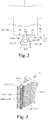
- Fig. 2 is an enlarged view of the protruding pieces 5a to 51.
- Fig. 3 is an enlarged view of a tooth portion of the laminated iron core 10 formed by laminating a plurality of iron core pieces 10a.
- the protruding pieces 5a to 51 are joined to the tooth pieces 3a to 31 protruding from the core main body 2 of the laminated iron core 10 via joint parts 8a to 81.
- the joint parts 8a to 81 each have a shape in which, when viewed from the lamination direction (plan view), the width in a direction orthogonal to the protrusion direction of the protruding pieces 5a to 51 (direction indicated by an arrow in the figure) gradually decreases toward the core main body 2 (W1 ⁇ W2).
- connection parts between the joint parts 8a to 81 and the tooth pieces 3a to 31 are referred to as gate parts.
- Recesses 13a to 131 and 15a to 151 are formed at both ends of the gate parts.
- the recesses 13a to 131 and 15a to 151 are substantially semicircular in plan view and are recessed toward the core main body 2 with respect to outermost surfaces 18 of the tooth pieces 3a to 31.
- groove-shaped recessed parts 21a and 21b extending in the lamination direction from the top to the bottom of the laminated iron core 10 are formed by the recesses 13a to 131 and 15a to 151 as shown in Fig. 3 .
- holes (bottomed holes) 12a to 121 which are open on one side, closed on the other side, and serve as filling holes for the adhesive are formed in protruding parts 25a to 251 of the teeth 11a to 111 as shown in Fig. 3 .
- the open side of each hole is defined as an adhesive injection port (introduction port), and the adhesive can be prevented from flowing out to the outside by being accumulated in the hole due to the closing side.
- the through holes 7a to 71 formed in the protruding pieces 5a to 51 that is, a distance D from the outermost surface 18 of each of the tooth pieces 3a to 31 to the corresponding one of the through holes 7a to 71 is reduced in consideration of the permeation rate of the adhesive, as long as the gate part which is a connection part between the protruding part and the tooth can be ensured.
- the through hole is formed as close to the tooth piece as possible.
- the through holes 7a to 71 are also formed at positions at which certain diameters can be obtained from the viewpoint of ensuring the holes 12a to 121 capable of sufficiently storing the adhesive required for permeation, which will be described later.
- the holes can be formed at positions where the effect of magnetic saturation can be minimized due to the protruding parts having holes being formed integrally with the main body of the laminate, it is possible to permeate the adhesive without providing the gate parts as shown in Fig. 8 , for example.
- the hole parts can be used as rotation prevention parts or positioning parts for adjacent components during assembly of the motor.
- a laminated iron core 20 (stator core) shown in Fig. 8 has a configuration in which multiple (twelve) split stators 35 are connected in the circumferential direction of a central axis.
- Each of the split stators 35 has an annular yoke part 35a extending in the circumferential direction and surrounding a rotor, and a tooth part 35b extending toward the central axis of the stator core from the yoke part 35a.
- the laminated iron core 20 is not provided with gate parts, and has through holes 37a to 371 serving as filling holes for the adhesive on the outer edge.
- the through holes 37a to 371 are formed such that an iron core piece 20b having no through hole is placed in the lowermost layer of the laminated iron core 20, and iron core pieces 20a provided with through holes 37 are laminated on the iron core piece 20b.
- Portions 39a to 391 protruding to the outer edge of the laminated iron core 20 in peripheral edges of the through holes 37a to 371 function as the abovementioned rotation prevention parts.
- the number of holes to be provided in the laminate is at least the same as or greater than the number of crimped parts. This configuration enables efficient permeation of the adhesive between the steel plates from a plurality of directions.
- the holes 12a to 121 formed in the laminated iron core 10 are filled with an adhesive by an injector (not shown), and the adhesive is permeated between the layers of a plurality of laminated iron core pieces 10a including the tooth pieces 3a to 31.
- the adhesive may be simultaneously injected into all holes 12a to 121, or may be sequentially injected in the circumferential direction of the circular core main body 2. Alternatively, the adhesive may be sequentially injected into each of pairs including two holes facing each other across the main body 2.
- Fig. 4 schematically shows how the adhesive permeates into the laminated iron core.
- Fig. 4 shows only the teeth 11a and 11b of the laminated iron core 10 for the sake of simplicity.
- the holes 12a and 12b function as a liquid reservoir.
- the adhesive permeates into a gap between the iron core pieces by capillary action from the holes 12a and 12b as a starting point (source) to the core main body 2 via the protruding pieces 5a and 5b and the teeth 11a and 11b, as indicated by a dotted line in Fig. 4 .
- the joint parts 8a to 81 serve as supply paths of the adhesive from the holes 12a and 12b to the gap between the steel plates, and the adhesive injected into the holes 12a and 12b permeates and spreads between the iron core pieces along the shapes of the protruding pieces 5a and 5b, the teeth 11a and 11b, and the like, due to capillary action as shown in Fig. 4 .
- the adhesive permeates into the protruding pieces 5a and 5b, the teeth 11a and 11b, and the like.
- the laminate in which, after the permeating adhesive is cured, the electromagnetic steel plates constituting the laminate are joined (tightened) with a prescribed force or more is released and obtained as a finished product.
- a low-viscosity adhesive is used in order to permeate the adhesive by capillary action.
- AE-780 with a viscosity of 9 Pa ⁇ s or an adhesive having lower viscosity than AE-780 is used.
- the adhesive before injection may be pressed and crushed to give fluidity.
- the adhesive may be cured by heating or the like after permeation.
- an adhesive absorbing means may be provided on the outer wall of the laminate between the teeth as a means for checking the completion of permeation of the adhesive into the laminate of the iron core pieces, and it may be determined that the permeation of the adhesive has been completed when the adhesive permeates into the adhesive absorbing means.
- a fluorescent substance may be added to the adhesive in advance, and whether or not the adhesive reaches the outer wall of the laminate may be checked using the fluorescent reaction with black light.
- the laminated iron core 10 according to the present embodiment constituted by the laminate of multiple iron core pieces 10a has groove-shaped recessed parts 21a and 21b, which are constituted by the recesses 13a to 131 and 15a to 151 shown in Fig. 2 and which extend in the lamination direction, at the connection parts between the protruding parts 25a and 25b and the teeth 11a and 11b (see Fig. 3 ).
- the connection part (gate part) between the protruding part and the tooth has a narrow width (width in the circumferential direction), and thus is long in the lamination direction.
- the gate parts fracture by applying a predetermined force to the protruding parts 25a and 25b from the circumferential direction of the laminated iron core 10, whereby the protruding parts 25a and 25b can be easily separated (removed) from the teeth 11a and 11b.
- Fig. 5 shows an example of fracture surfaces remaining on the tip surfaces of the teeth 11a and 11b after the protruding parts 25a and 25b are removed. Since the lateral width of each gate part is reduced as described above, no iron core pieces remain in fracture portions 28a and 28b as shown in Fig. 5 . Thus, the protruding parts 25a and 25b can be removed with the fracture surfaces not protruding from the end faces of the teeth 11a and 11b (not protruding from the surface of the product).
- the fracture surfaces do not protrude from the outermost wall surface of the laminate, so that the laminate can be smoothly placed into a storage case.
- the, method for manufacturing a laminated iron core according to the present embodiment includes: injecting an adhesive into a hole part formed so as to extend in a lamination direction of a laminate obtained by laminating a plurality of steel plates having a plurality of holes; and permeating the adhesive between the adjacent steel plates of the laminate.
- the adhesive can be uniformly permeated into a thin layer form between the steel plates constituting the laminate, whereby the thickness of the laminate (laminated iron core) in the lamination direction can be reduced, and the thin steel plates can be reliably laminated.
- the permeation step can be simplified by using capillary action which occurs between the adjacent steel plates of the laminate when the adhesive is permeated between the steel plates.
- the thickness of the adhesive is smaller (for example, 1 ⁇ m or less) than that of the adhesive formed by coating, and it is possible to prevent the adhesive from being unevenly permeated.
- the space factor of the core in the motor is increased, and the height of the motor can be reduced even if the number of laminated steel plates is increased.
- eddy current in the steel plates of the laminated iron core can be reduced to decrease energy loss due to eddy current loss, and further, iron loss can be reduced because a resin layer formed by the adhesive serves as an insulator between the steel plates. Further, the adhesive can be permeated with a simple structure, whereby the mass productivity of the laminated iron core is improved.
- the protruding parts provided with the filling holes for the adhesive are formed into a shape that facilitates removal of the protruding parts from the main body of the laminate and the protruding parts are removed after the adhesive is cured. Therefore, the cause for interruption of the magnetic path and the magnetic saturation of the laminate can be eliminated, and deterioration in characteristics of the motor or the like using the laminate can be prevented. Further, each of the protruding parts has a shape satisfying the minimum required function, considering that the protruding parts are members to be discarded after removal. Thus, a steel plate material can be saved in terms of use amount.
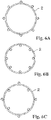
- the holes to be filled with an adhesive extending in the lamination direction are not limited to be arranged outside the core main body 2 in the radial direction (this arrangement is described in the above embodiment) as indicated by small circles in Fig. 6A .
- they may be arranged inside the core main body 2 in the radial direction as shown in Fig. 6B .
- they may be arranged both outside and inside the core main body 2 in the radial direction as shown in Fig. 6C .
- the holes can be arranged according to the application of the laminate, the mounting location in the product, and the like.
- the filling holes for an adhesive formed in the laminated iron core are also deep, and it is assumed that the injected adhesive does not easily reach the lower layer portion of the holes.
- iron core pieces provided with through holes in protruding pieces are laminated in all layers including the lowermost layer such that filling holes penetrating from the uppermost layer to the lowermost layer are formed. Then, the lowermost layers of the holes are closed, and the adhesive is injected from the openings in the uppermost layers of the holes. After the holes are filled with the adhesive to some extent, the openings in the uppermost layers of the holes are closed, and the adhesive is injected from the openings in the lowermost layers of the holes. Thus, the adhesive fills such deep holes formed in a thick laminate.
- the iron core piece 10b shown in Fig. 1 having no through holes in the protruding pieces is used in an intermediate layer of the laminate, and the iron core pieces 10a having through holes in the protruding pieces are used for laminates laminated on and under the iron core piece 10b.
- the adhesive can be injected from openings of holes formed in one of the laminates and openings of holes formed in the other of the laminates across the iron core piece 10b.
- the thick laminate may be divided into a plurality of laminates each having a smaller number of laminated iron core pieces, and the plurality of laminates may be combined (laminated in the lamination direction) after the adhesive is injected from openings of holes formed in each of the divided laminates.
- the adhesive can be quickly and reliably injected from the openings of the holes in each of the divided laminates.
- the above embodiment has a configuration in which, in all the teeth, the adhesive injected into the holes formed in the protruding parts is permeated into all the layers.
- the present invention is not limited thereto.
- a laminated iron core 30 in Fig. 7 is configured such that the laminate is divided into three layers, which are an upper layer, a middle layer, and a lower layer, and the adhesive may be permeated into each of the three layers.
- teeth 31a, 31d, 31g, and 31j are made to correspond to the upper layer of the laminate
- teeth 31c, 31f, 31i, and 311 are made to correspond to the middle layer of the laminate
- teeth 31b, 31e, 31h, and 31k are made to correspond to the lower layer of the laminate.
- Protruding parts 35a, 35d, 35g, and 35j at the tips of the teeth in group 1 are formed with holes for permeating the adhesive into the upper layer.
- protruding parts 35c, 35f, 35i, and 351 at the tips of the teeth in group 2 are formed with holes for permeating the adhesive into the middle layer
- protruding parts 35b, 35e, 35h, and 35k at the tips of the teeth in group 3 are formed with holes for permeating the adhesive into the lower layer.
- the adhesive when the adhesive is injected into the holes 32a to 321, the adhesive can be quickly permeated into each of the upper layer, the middle layer, and the lower layer. Further, in the laminated iron core 30 in Fig. 7 , the length of the protruding part in the lamination direction is short, so that the length of the connection part (gate part) between the protruding part and the tooth is also short in the lamination direction. Therefore, after the adhesive is cured, the protruding parts can be separated by a slight external force, which facilitates the removal of the protruding parts.
- the method for manufacturing the laminated iron core 10 described above can be applied not only to a stator (stator) of the motor but also to a rotor (rotor) of the motor. Therefore, it is possible to manufacture a motor with reduced eddy current loss by using a laminated iron core which is thin in the lamination direction.
Landscapes
- Engineering & Computer Science (AREA)
- Manufacturing & Machinery (AREA)
- Power Engineering (AREA)
- Iron Core Of Rotating Electric Machines (AREA)
- Manufacture Of Motors, Generators (AREA)
Abstract
Description
- The present invention relates to a method for manufacturing a laminated iron core incorporated in, for example, a motor.
- As a conventionally known method for manufacturing a laminated iron core, a method for laminating a plurality of punched steel plates by crimping or welding is mainly used. However, in such methods, connection portions of the steel plates become conductive to cause iron loss.
- Iron loss may cause deterioration in characteristics of a motor or the like. In order to address improvement of the characteristics, steel plates have been reduced in thickness, or development of new materials has been carried out. Further, a glue lamination process with less iron loss has been developed in recent years.
- Patent Literature 1 discloses a method for manufacturing a laminated iron core. Specifically, iron core pieces each having an iron core piece body and a joint part protruding from the iron core piece body are formed by punching material plates coated with a thermosetting adhesive on the surface, a prescribed number of iron core pieces are connected and laminated by connecting the joint parts of the iron core pieces to each other by crimping, and then, the thermosetting adhesive is cured to bond the iron core pieces.
-
Patent Literature 2 discloses a method for manufacturing an amorphous laminated iron core, the method including: punching an iron core piece from an amorphous thin plate material; and injecting an adhesive linking agent into a connection hole formed in the iron core piece so as to fill the connection hole with the adhesive linking agent. -
- Patent Literature 1:
JP 11-308821 A - Patent Literature 2:
JP 2003-309952 A - The glue lamination process disclosed in Patent Literature 1 is based on a method for laminating steel plates, which are cut into a predetermined shape using a molding device equipped with a die and a punch, with an adhesive applied to the steel plates. However, problems remain in the method for applying the adhesive during lamination.
- That is, in the glue lamination process by applying an adhesive, when the steel plates are pressurized after the application, the adhesive protrudes, and the protruding adhesive may adhere to a jig or a mold, which may cause deformation of a laminated product, etc., as well as damage on the mold and the jig. Therefore, there arises a problem that the frequency of defects during production increases, and the product yield also deteriorates.
- The method disclosed in
Patent Literature 2 is devised in consideration of difficulty in laminating amorphous thin plate materials. This method is advantageous in that cracks and the like do not occur. However, the connection hole formed in the iron core body is used as a bonding hole, which may cause interruption of a magnetic path or magnetic saturation in the laminate. Therefore, when a laminated iron core manufactured by the method disclosed inPatent Literature 2 is used for, for example, a motor, it is considered that the motor characteristics are deteriorated. - The present invention has been made in view of the abovementioned problems, and an object of the present invention is to provide a method for manufacturing a laminated iron core by a glue lamination process with less iron loss.
- The following configuration is provided as a means for achieving the above object and solving the abovementioned problem. That is, a first exemplary invention of the present application provides a method for manufacturing a laminated iron core, the method characterized by including: a step for forming a laminate by laminating a plurality of steel plates having a plurality of holes; a step for injecting an adhesive into a hole part constituted by the plurality of holes being continuous in a lamination direction of the laminate; and a step for permeating the injected adhesive between the steel plates adjacent to each other in the laminate.
- A second exemplary invention of the present application provides a laminated iron core characterized by being manufactured using the method for manufacturing a laminated iron core according to the first exemplary invention.
- A third exemplary invention of the present application provides a laminate obtained by laminating a plurality of steel plates, the laminate characterized in that a plurality of hole parts which extends in a lamination direction of the laminate and which is located at positions distant from a main body of the laminate or formed integrally with the main body is used as a filling part for an adhesive, and the plurality of steel plates is bonded to each other by permeating the adhesive between the steel plates adjacent to each other using capillary action which occurs between the plurality of steel plates.
- A fourth exemplary invention of the present application provides a motor characterized by using the laminate according to the third exemplary invention.
- According to the present invention, the adhesive can be uniformly permeated between the steel plates constituting the laminate by utilizing capillary action, whereby it is possible to reduce iron loss and reduce the thickness of the laminate in the lamination direction.
-
-
Fig. 1 is a diagram for describing a manufacturing process of a laminated iron core according to an embodiment of the present invention. -
Fig. 2 is an enlarged view of a protruding piece formed on an iron core piece. -
Fig. 3 is an enlarged view of a tooth portion of a laminated iron core formed by laminating a plurality of iron core pieces. -
Fig. 4 is a diagram schematically showing how an adhesive permeates into the laminated iron core. -
Fig. 5 is a diagram showing an example of fracture surfaces remaining on tip surfaces of teeth after protruding parts are removed. -
Fig. 6A is a diagram showing an example of arrangement of holes to be filled with an adhesive. -
Fig. 6B is a diagram showing another example of arrangement of holes to be filled with an adhesive. -
Fig. 6C is a diagram showing another example of arrangement of holes to be filled with an adhesive. -
Fig. 7 is a diagram showing an example in which an adhesive is permeated into each layer of a laminate divided into three layers, which are an upper layer, a middle layer, and a lower layer. -
Fig. 8 is a diagram for describing a manufacturing process of a laminated iron core having no gate parts. - An embodiment of the present invention will be described in detail below with reference to the accompanying drawings.
Fig. 1 is a diagram for describing a manufacturing process of a laminated iron core according to the present embodiment. As shown inFig. 1 , a laminatediron core 10 is manufactured by laminating multipleiron core pieces 10a in a plate thickness direction. Each of theiron core pieces 10a is a material to be processed and is obtained by cutting out an electromagnetic steel plate into a predetermined shape by pressing, laser processing, wire cutting, or the like. That is, the laminatediron core 10 is a laminate in which multipleiron core pieces 10a having the same shape in a plan view are placed in a jig or a mold and laminated. - The laminated
iron core 10 is, for example, a stator core of a motor. Each of the plurality ofiron core pieces 10a hastooth pieces 3a to 31 extending outward in the radial direction of the motor from a coremain body 2. Protrudingpieces 5a to 51 are formed at the tip parts (opposite to the side connected to the core main body 2) of thetooth pieces 3a to 31, and throughholes 7a to 71 are formed in theprotruding pieces 5a to 51. - As shown in
Fig. 1 , thetooth pieces 3a to 31 constituteteeth 11a to 111 of the laminated iron core 10 (stator core) after lamination. - Further, in the laminated
iron core 10, aniron core piece 10b having no through hole in the protruding piece is used as the iron core piece in the lowermost layer of the laminate in order to form a filling hole for an adhesive described later, as shown inFig. 1 . -
Fig. 2 is an enlarged view of theprotruding pieces 5a to 51. Further,Fig. 3 is an enlarged view of a tooth portion of the laminatediron core 10 formed by laminating a plurality ofiron core pieces 10a. - As shown in
Fig. 2 , theprotruding pieces 5a to 51 are joined to thetooth pieces 3a to 31 protruding from the coremain body 2 of the laminatediron core 10 viajoint parts 8a to 81. Thejoint parts 8a to 81 each have a shape in which, when viewed from the lamination direction (plan view), the width in a direction orthogonal to the protrusion direction of theprotruding pieces 5a to 51 (direction indicated by an arrow in the figure) gradually decreases toward the core main body 2 (W1 < W2). - Connection parts between the
joint parts 8a to 81 and thetooth pieces 3a to 31 (portions of the joint parts closest to the tooth pieces) are referred to as gate parts. Recesses 13a to 131 and 15a to 151 are formed at both ends of the gate parts. Therecesses 13a to 131 and 15a to 151 are substantially semicircular in plan view and are recessed toward the coremain body 2 with respect tooutermost surfaces 18 of thetooth pieces 3a to 31. - When the
iron core pieces 10a are laminated, groove-shapedrecessed parts 21a and 21b extending in the lamination direction from the top to the bottom of the laminatediron core 10 are formed by therecesses 13a to 131 and 15a to 151 as shown inFig. 3 . - Further, because the iron core piece in the lowermost layer of the
laminated iron core 10 does not have a through hole as described above, holes (bottomed holes) 12a to 121 which are open on one side, closed on the other side, and serve as filling holes for the adhesive are formed in protrudingparts 25a to 251 of theteeth 11a to 111 as shown inFig. 3 . The open side of each hole is defined as an adhesive injection port (introduction port), and the adhesive can be prevented from flowing out to the outside by being accumulated in the hole due to the closing side. - Regarding the positions of the through
holes 7a to 71 formed in the protrudingpieces 5a to 51, that is, a distance D from theoutermost surface 18 of each of thetooth pieces 3a to 31 to the corresponding one of the throughholes 7a to 71 is reduced in consideration of the permeation rate of the adhesive, as long as the gate part which is a connection part between the protruding part and the tooth can be ensured. Specifically, the through hole is formed as close to the tooth piece as possible. In addition, the throughholes 7a to 71 are also formed at positions at which certain diameters can be obtained from the viewpoint of ensuring theholes 12a to 121 capable of sufficiently storing the adhesive required for permeation, which will be described later. - In a case where the holes can be formed at positions where the effect of magnetic saturation can be minimized due to the protruding parts having holes being formed integrally with the main body of the laminate, it is possible to permeate the adhesive without providing the gate parts as shown in
Fig. 8 , for example. In addition, the hole parts can be used as rotation prevention parts or positioning parts for adjacent components during assembly of the motor. - That is, a laminated iron core 20 (stator core) shown in
Fig. 8 has a configuration in which multiple (twelve) splitstators 35 are connected in the circumferential direction of a central axis. Each of thesplit stators 35 has anannular yoke part 35a extending in the circumferential direction and surrounding a rotor, and atooth part 35b extending toward the central axis of the stator core from theyoke part 35a. - The
laminated iron core 20 is not provided with gate parts, and has throughholes 37a to 371 serving as filling holes for the adhesive on the outer edge. The throughholes 37a to 371 are formed such that aniron core piece 20b having no through hole is placed in the lowermost layer of thelaminated iron core 20, andiron core pieces 20a provided with throughholes 37 are laminated on theiron core piece 20b.Portions 39a to 391 protruding to the outer edge of thelaminated iron core 20 in peripheral edges of the throughholes 37a to 371 function as the abovementioned rotation prevention parts. - If crimped parts for crimping and fixing a plurality of steel plates are provided, the number of holes to be provided in the laminate is at least the same as or greater than the number of crimped parts. This configuration enables efficient permeation of the adhesive between the steel plates from a plurality of directions.
- Next, a method for permeating the adhesive into the laminated iron core according to the present embodiment will be described. Here, the
holes 12a to 121 formed in thelaminated iron core 10 are filled with an adhesive by an injector (not shown), and the adhesive is permeated between the layers of a plurality of laminatediron core pieces 10a including thetooth pieces 3a to 31. - The adhesive may be simultaneously injected into all
holes 12a to 121, or may be sequentially injected in the circumferential direction of the circular coremain body 2. Alternatively, the adhesive may be sequentially injected into each of pairs including two holes facing each other across themain body 2. -
Fig. 4 schematically shows how the adhesive permeates into the laminated iron core.Fig. 4 shows only theteeth laminated iron core 10 for the sake of simplicity. For example, when theholes holes - In the
laminated iron core 10, multiple iron core pieces are laminated adjacent to each other while maintaining a surface contact state. Therefore, the adhesive permeates into a gap between the iron core pieces by capillary action from theholes main body 2 via the protrudingpieces teeth Fig. 4 . - That is, the
joint parts 8a to 81 serve as supply paths of the adhesive from theholes holes pieces teeth Fig. 4 . Thus, the adhesive permeates into the protrudingpieces teeth - Here, a low-viscosity adhesive is used in order to permeate the adhesive by capillary action. For example, AE-780 with a viscosity of 9 Pa·s or an adhesive having lower viscosity than AE-780 is used. Further, the adhesive before injection may be pressed and crushed to give fluidity. Depending on the type of adhesive to be used, the adhesive may be cured by heating or the like after permeation.
- When the
laminated iron core 10 in which the adhesive does not uniformly permeate into the protrudingpieces teeth main body 2 of thelaminated iron core 10 is used for, for example, a rotor or the like of the motor, it is assumed that vibration may occur during rotation of the motor due to non-uniformity of the adhesive. In view of this, for example, an adhesive absorbing means may be provided on the outer wall of the laminate between the teeth as a means for checking the completion of permeation of the adhesive into the laminate of the iron core pieces, and it may be determined that the permeation of the adhesive has been completed when the adhesive permeates into the adhesive absorbing means. - Alternatively, a fluorescent substance may be added to the adhesive in advance, and whether or not the adhesive reaches the outer wall of the laminate may be checked using the fluorescent reaction with black light.
- The
laminated iron core 10 according to the present embodiment constituted by the laminate of multipleiron core pieces 10a has groove-shaped recessedparts 21a and 21b, which are constituted by therecesses 13a to 131 and 15a to 151 shown inFig. 2 and which extend in the lamination direction, at the connection parts between the protrudingparts teeth Fig. 3 ). Thus, the connection part (gate part) between the protruding part and the tooth has a narrow width (width in the circumferential direction), and thus is long in the lamination direction. - Therefore, after the adhesive is cured, the gate parts fracture by applying a predetermined force to the protruding
parts laminated iron core 10, whereby the protrudingparts teeth -
Fig. 5 shows an example of fracture surfaces remaining on the tip surfaces of theteeth parts fracture portions Fig. 5 . Thus, the protrudingparts teeth - Accordingly, after the protruding
parts - As described above, the, method for manufacturing a laminated iron core according to the present embodiment includes: injecting an adhesive into a hole part formed so as to extend in a lamination direction of a laminate obtained by laminating a plurality of steel plates having a plurality of holes; and permeating the adhesive between the adjacent steel plates of the laminate. With this method, the adhesive can be uniformly permeated into a thin layer form between the steel plates constituting the laminate, whereby the thickness of the laminate (laminated iron core) in the lamination direction can be reduced, and the thin steel plates can be reliably laminated.
- Further, the permeation step can be simplified by using capillary action which occurs between the adjacent steel plates of the laminate when the adhesive is permeated between the steel plates. In addition, the thickness of the adhesive is smaller (for example, 1 µm or less) than that of the adhesive formed by coating, and it is possible to prevent the adhesive from being unevenly permeated. Thus, for example, the space factor of the core in the motor is increased, and the height of the motor can be reduced even if the number of laminated steel plates is increased.
- As a result, eddy current in the steel plates of the laminated iron core can be reduced to decrease energy loss due to eddy current loss, and further, iron loss can be reduced because a resin layer formed by the adhesive serves as an insulator between the steel plates. Further, the adhesive can be permeated with a simple structure, whereby the mass productivity of the laminated iron core is improved.
- Furthermore, it is not necessary to pressurize the steel plates to permeate the adhesive between the steel plates, which can prevent the adhesive from protruding and adhering to the jig, the mold, or the like.
- In addition, the protruding parts provided with the filling holes for the adhesive are formed into a shape that facilitates removal of the protruding parts from the main body of the laminate and the protruding parts are removed after the adhesive is cured. Therefore, the cause for interruption of the magnetic path and the magnetic saturation of the laminate can be eliminated, and deterioration in characteristics of the motor or the like using the laminate can be prevented. Further, each of the protruding parts has a shape satisfying the minimum required function, considering that the protruding parts are members to be discarded after removal. Thus, a steel plate material can be saved in terms of use amount.
- The present invention is not limited to the above embodiment, and various modifications are possible.
- The holes to be filled with an adhesive extending in the lamination direction are not limited to be arranged outside the core
main body 2 in the radial direction (this arrangement is described in the above embodiment) as indicated by small circles inFig. 6A . For example, they may be arranged inside the coremain body 2 in the radial direction as shown inFig. 6B . Alternatively, they may be arranged both outside and inside the coremain body 2 in the radial direction as shown inFig. 6C . In other words, the holes can be arranged according to the application of the laminate, the mounting location in the product, and the like. - When the laminate is thick in the lamination direction due to a large number of laminated iron core pieces, the filling holes for an adhesive formed in the laminated iron core are also deep, and it is assumed that the injected adhesive does not easily reach the lower layer portion of the holes.
- In view of this, unlike the abovementioned embodiment, iron core pieces provided with through holes in protruding pieces are laminated in all layers including the lowermost layer such that filling holes penetrating from the uppermost layer to the lowermost layer are formed. Then, the lowermost layers of the holes are closed, and the adhesive is injected from the openings in the uppermost layers of the holes. After the holes are filled with the adhesive to some extent, the openings in the uppermost layers of the holes are closed, and the adhesive is injected from the openings in the lowermost layers of the holes. Thus, the adhesive fills such deep holes formed in a thick laminate.
- Further, as a measure to address a thick laminate, for example, the
iron core piece 10b shown inFig. 1 having no through holes in the protruding pieces is used in an intermediate layer of the laminate, and theiron core pieces 10a having through holes in the protruding pieces are used for laminates laminated on and under theiron core piece 10b. With this configuration, the adhesive can be injected from openings of holes formed in one of the laminates and openings of holes formed in the other of the laminates across theiron core piece 10b. - As a further measure to address a thick laminate, the thick laminate may be divided into a plurality of laminates each having a smaller number of laminated iron core pieces, and the plurality of laminates may be combined (laminated in the lamination direction) after the adhesive is injected from openings of holes formed in each of the divided laminates. With this configuration, the adhesive can be quickly and reliably injected from the openings of the holes in each of the divided laminates.
- The above embodiment has a configuration in which, in all the teeth, the adhesive injected into the holes formed in the protruding parts is permeated into all the layers. However, the present invention is not limited thereto. For example, a
laminated iron core 30 inFig. 7 is configured such that the laminate is divided into three layers, which are an upper layer, a middle layer, and a lower layer, and the adhesive may be permeated into each of the three layers. - Specifically,
teeth teeth teeth parts - Similarly, protruding
parts group 2 are formed with holes for permeating the adhesive into the middle layer, and protrudingparts - With this configuration, when the adhesive is injected into the
holes 32a to 321, the adhesive can be quickly permeated into each of the upper layer, the middle layer, and the lower layer. Further, in thelaminated iron core 30 inFig. 7 , the length of the protruding part in the lamination direction is short, so that the length of the connection part (gate part) between the protruding part and the tooth is also short in the lamination direction. Therefore, after the adhesive is cured, the protruding parts can be separated by a slight external force, which facilitates the removal of the protruding parts. - The method for manufacturing the
laminated iron core 10 described above can be applied not only to a stator (stator) of the motor but also to a rotor (rotor) of the motor. Therefore, it is possible to manufacture a motor with reduced eddy current loss by using a laminated iron core which is thin in the lamination direction. -
- 2
- core main body
- 3a to 31
- tooth piece
- 5a to 51
- protruding piece
- 7a to 71, 37a to 371
- through hole
- 8a to 81
- joint part
- 10, 20
- laminated iron core
- 10a, 10b, 20a, 20b
- iron core piece
- 11a to 111
- tooth
- 12a to 121
- hole
- 13a to 131, 15a to 151
- recess
- 25a to 251
- protruding part
- 35
- split stator
Claims (15)
- A method for manufacturing a laminated iron core, the method characterized by comprising:a step for forming a laminate by laminating a plurality of steel plates (10a, 10b) having a plurality of holes (7a to 71, 37a to 371);a step for injecting an adhesive into a hole part (12a to 121) constituted by the plurality of holes (7a to 71, 37a to 371) being continuous in a lamination direction of the laminate; anda step for permeating the injected adhesive between the steel plates adjacent to each other in the laminate.
- The method for manufacturing a laminated iron core according to claim 1, characterized in that the adhesive is permeated to spread between the steel plates adjacent to each other in the laminate using capillary action that occurs between the steel plates.
- The method for manufacturing a laminated iron core according to claim 1 or 2, characterized in that the hole part (12a to 121) is formed in a protruding part (25a to 251) provided at a position distant from a main body (2) of the laminate, and the protruding part (25a to 251) is removable.
- The method for manufacturing a laminated iron core according to claim 3, characterized in that the protruding part (25a to 251) and the main body (2) of the laminate are connected to each other at a joint part (8a to 81) having a width smaller than a width of the protruding part (25a to 251) in a circumferential direction of the laminate.
- The method for manufacturing a laminated iron core according to claim 4, characterized in that the joint part (8a to 81) has a shape that gradually decreases toward the main body (2) of the laminate in a width direction when viewed in the lamination direction of the laminate.
- The method for manufacturing a laminated iron core according to any one of claims 3 to 5, characterized in that groove-shaped recessed parts (21a, 21b) that are recessed toward inside of the main body (2) from an outer wall surface of the main body (2) are formed at both ends of a portion where the protruding part (25a to 251) is connected to the main body (2) of the laminate.
- The method for manufacturing a laminated iron core according to claim 1 or 2, characterized in that the hole part (12a to 121) and the main body (2) of the laminate are integrally formed.
- The method for manufacturing a laminated iron core according to any one of claims 1 to 7, characterized in that the hole part (12a to 121) is open in one end and closed in the other end.
- The method for manufacturing a laminated iron core according to any one of claims 1 to 8, characterized in that, when a crimped part for crimping and fixing the plurality of steel plates (10a, 10b) is provided, the number of the hole parts (12a to 121) is at least the same as or greater than the number of the crimped parts.
- The method for manufacturing a laminated iron core according to any one of claims 7 to 9, characterized in that the hole part (12a to 121) is provided on a circumferential surface of an outer wall of the main body (2) of the laminate, a circumferential surface of an inner wall of the laminate, or both the circumferential surface of the outer wall and the circumferential surface of the inner wall.
- A laminated iron core characterized by being manufactured by the method for manufacturing a laminated iron core according to any one of claims 1 to 10.
- The laminated iron core according to claim 11, characterized by being used as a rotor of a motor or a stator of a motor.
- A laminate obtained by laminating a plurality of steel plates (10a, 10b), the laminate characterized in that a plurality of hole parts (12a to 121) which extends in a lamination direction of the laminate and which is located at positions distant from a main body (2) of the laminate or formed integrally with the main body (2) is used as a filling part for an adhesive, and the plurality of steel plates (10a, 10b) is bonded to each other by permeating the adhesive between the steel plates adjacent to each other using capillary action that occurs between the plurality of steel plates.
- The laminate according to claim 13, characterized by being a laminated iron core (10, 20) constituting a rotor core or a stator core of a motor.
- A motor characterized by using the laminate according to claim 13.
Applications Claiming Priority (1)
| Application Number | Priority Date | Filing Date | Title |
|---|---|---|---|
| JP2020091476A JP2021191039A (en) | 2020-05-26 | 2020-05-26 | Manufacturing method of laminated iron core |
Publications (2)
| Publication Number | Publication Date |
|---|---|
| EP3916969A1 true EP3916969A1 (en) | 2021-12-01 |
| EP3916969B1 EP3916969B1 (en) | 2023-05-03 |
Family
ID=75362438
Family Applications (1)
| Application Number | Title | Priority Date | Filing Date |
|---|---|---|---|
| EP21166603.7A Active EP3916969B1 (en) | 2020-05-26 | 2021-04-01 | Method for manufacturing laminated iron core |
Country Status (3)
| Country | Link |
|---|---|
| EP (1) | EP3916969B1 (en) |
| JP (1) | JP2021191039A (en) |
| CN (1) | CN113726106A (en) |
Families Citing this family (1)
| Publication number | Priority date | Publication date | Assignee | Title |
|---|---|---|---|---|
| WO2026079123A1 (en) * | 2024-10-10 | 2026-04-16 | 三菱電機株式会社 | Stator of rotary electric machine, hoist of elevator, and method of manufacturing same |
Citations (5)
| Publication number | Priority date | Publication date | Assignee | Title |
|---|---|---|---|---|
| JPH11308821A (en) | 1998-04-22 | 1999-11-05 | Mitsui High Tec Inc | Manufacturing method of laminated core |
| JP2003309952A (en) | 2002-04-12 | 2003-10-31 | Mitsui High Tec Inc | Manufacturing method of amorphous laminated iron core |
| JP2015136228A (en) * | 2014-01-17 | 2015-07-27 | 三菱電機株式会社 | Laminated core, stator, method of manufacturing laminated core, method of manufacturing stator |
| US20160329783A1 (en) * | 2014-01-10 | 2016-11-10 | Mitsui High-Tec, Inc. | Method for manufacturing laminated core |
| WO2020045937A1 (en) * | 2018-08-30 | 2020-03-05 | 엘지이노텍 주식회사 | Motor |
Family Cites Families (1)
| Publication number | Priority date | Publication date | Assignee | Title |
|---|---|---|---|---|
| CA2967562A1 (en) * | 2014-11-14 | 2016-05-19 | Mitsui High-Tec, Inc. | Laminated core and method for manufacturing same |
-
2020
- 2020-05-26 JP JP2020091476A patent/JP2021191039A/en active Pending
-
2021
- 2021-04-01 EP EP21166603.7A patent/EP3916969B1/en active Active
- 2021-05-25 CN CN202110570521.0A patent/CN113726106A/en active Pending
Patent Citations (5)
| Publication number | Priority date | Publication date | Assignee | Title |
|---|---|---|---|---|
| JPH11308821A (en) | 1998-04-22 | 1999-11-05 | Mitsui High Tec Inc | Manufacturing method of laminated core |
| JP2003309952A (en) | 2002-04-12 | 2003-10-31 | Mitsui High Tec Inc | Manufacturing method of amorphous laminated iron core |
| US20160329783A1 (en) * | 2014-01-10 | 2016-11-10 | Mitsui High-Tec, Inc. | Method for manufacturing laminated core |
| JP2015136228A (en) * | 2014-01-17 | 2015-07-27 | 三菱電機株式会社 | Laminated core, stator, method of manufacturing laminated core, method of manufacturing stator |
| WO2020045937A1 (en) * | 2018-08-30 | 2020-03-05 | 엘지이노텍 주식회사 | Motor |
Also Published As
| Publication number | Publication date |
|---|---|
| CN113726106A (en) | 2021-11-30 |
| EP3916969B1 (en) | 2023-05-03 |
| JP2021191039A (en) | 2021-12-13 |
Similar Documents
| Publication | Publication Date | Title |
|---|---|---|
| JP6406788B2 (en) | Manufacturing method of laminated iron core | |
| CN109643940B (en) | Laminated core, method for manufacturing laminated core, and armature using laminated core | |
| JP6066936B2 (en) | Laminated core manufacturing method, stator manufacturing method | |
| US20190028006A1 (en) | Manufacturing method of laminated steel and laminated steel manufacturing apparatus | |
| JP6136718B2 (en) | Rotating electrical machine rotor and method of manufacturing the same | |
| KR20170007166A (en) | Mtehod for manufacturing rotary electric machine rotor | |
| JP2007306726A (en) | Magnet-embedded rotor and molding die | |
| JP2011182552A (en) | Rotor core and rotating electrical machine core | |
| EP3916969B1 (en) | Method for manufacturing laminated iron core | |
| CN105229898A (en) | The magnet embedded type rotor of electric rotating machine | |
| CN110268608B (en) | Manufacturing method of components for rotating electrical machines | |
| JP2014176891A (en) | Manufacturing method of core | |
| JP4073705B2 (en) | Rotating electric machine | |
| JP6670135B2 (en) | Manufacturing method of laminated core | |
| JP5310460B2 (en) | Manufacturing method of laminated core | |
| US10576690B2 (en) | Joining method, joining body, stator for dynamo-electric machine, and method for manufacturing stator for dynamo-electric machine | |
| CN112042090B (en) | Method used to connect laminated sections | |
| JP2013123316A (en) | Rotor core and method of manufacturing the same | |
| JP5647444B2 (en) | Resolver insulator, resolver, and method for manufacturing the same | |
| JP2023014657A (en) | Iron core manufacturing method, iron core | |
| JP2019022247A (en) | Lamination core and manufacturing method therefor | |
| JP2022048726A (en) | Core portion of rotary electric machine | |
| JP2021118664A (en) | Stator and manufacturing method thereof | |
| JP6724753B2 (en) | Stator and method of manufacturing stator | |
| JP2019097306A (en) | Formation method for stator coil of rotary electric machine |
Legal Events
| Date | Code | Title | Description |
|---|---|---|---|
| PUAI | Public reference made under article 153(3) epc to a published international application that has entered the european phase |
Free format text: ORIGINAL CODE: 0009012 |
|
| STAA | Information on the status of an ep patent application or granted ep patent |
Free format text: STATUS: THE APPLICATION HAS BEEN PUBLISHED |
|
| AK | Designated contracting states |
Kind code of ref document: A1 Designated state(s): AL AT BE BG CH CY CZ DE DK EE ES FI FR GB GR HR HU IE IS IT LI LT LU LV MC MK MT NL NO PL PT RO RS SE SI SK SM TR |
|
| B565 | Issuance of search results under rule 164(2) epc |
Effective date: 20210924 |
|
| STAA | Information on the status of an ep patent application or granted ep patent |
Free format text: STATUS: REQUEST FOR EXAMINATION WAS MADE |
|
| 17P | Request for examination filed |
Effective date: 20220601 |
|
| RBV | Designated contracting states (corrected) |
Designated state(s): AL AT BE BG CH CY CZ DE DK EE ES FI FR GB GR HR HU IE IS IT LI LT LU LV MC MK MT NL NO PL PT RO RS SE SI SK SM TR |
|
| GRAP | Despatch of communication of intention to grant a patent |
Free format text: ORIGINAL CODE: EPIDOSNIGR1 |
|
| STAA | Information on the status of an ep patent application or granted ep patent |
Free format text: STATUS: GRANT OF PATENT IS INTENDED |
|
| INTG | Intention to grant announced |
Effective date: 20221115 |
|
| GRAS | Grant fee paid |
Free format text: ORIGINAL CODE: EPIDOSNIGR3 |
|
| GRAA | (expected) grant |
Free format text: ORIGINAL CODE: 0009210 |
|
| STAA | Information on the status of an ep patent application or granted ep patent |
Free format text: STATUS: THE PATENT HAS BEEN GRANTED |
|
| AK | Designated contracting states |
Kind code of ref document: B1 Designated state(s): AL AT BE BG CH CY CZ DE DK EE ES FI FR GB GR HR HU IE IS IT LI LT LU LV MC MK MT NL NO PL PT RO RS SE SI SK SM TR |
|
| REG | Reference to a national code |
Ref country code: GB Ref legal event code: FG4D |
|
| REG | Reference to a national code |
Ref country code: AT Ref legal event code: REF Ref document number: 1565523 Country of ref document: AT Kind code of ref document: T Effective date: 20230515 Ref country code: CH Ref legal event code: EP |
|
| REG | Reference to a national code |
Ref country code: DE Ref legal event code: R096 Ref document number: 602021002131 Country of ref document: DE |
|
| REG | Reference to a national code |
Ref country code: IE Ref legal event code: FG4D |
|
| REG | Reference to a national code |
Ref country code: LT Ref legal event code: MG9D |
|
| REG | Reference to a national code |
Ref country code: NL Ref legal event code: MP Effective date: 20230503 |
|
| REG | Reference to a national code |
Ref country code: AT Ref legal event code: MK05 Ref document number: 1565523 Country of ref document: AT Kind code of ref document: T Effective date: 20230503 |
|
| PG25 | Lapsed in a contracting state [announced via postgrant information from national office to epo] |
Ref country code: SE Free format text: LAPSE BECAUSE OF FAILURE TO SUBMIT A TRANSLATION OF THE DESCRIPTION OR TO PAY THE FEE WITHIN THE PRESCRIBED TIME-LIMIT Effective date: 20230503 Ref country code: PT Free format text: LAPSE BECAUSE OF FAILURE TO SUBMIT A TRANSLATION OF THE DESCRIPTION OR TO PAY THE FEE WITHIN THE PRESCRIBED TIME-LIMIT Effective date: 20230904 Ref country code: NO Free format text: LAPSE BECAUSE OF FAILURE TO SUBMIT A TRANSLATION OF THE DESCRIPTION OR TO PAY THE FEE WITHIN THE PRESCRIBED TIME-LIMIT Effective date: 20230803 Ref country code: NL Free format text: LAPSE BECAUSE OF FAILURE TO SUBMIT A TRANSLATION OF THE DESCRIPTION OR TO PAY THE FEE WITHIN THE PRESCRIBED TIME-LIMIT Effective date: 20230503 Ref country code: ES Free format text: LAPSE BECAUSE OF FAILURE TO SUBMIT A TRANSLATION OF THE DESCRIPTION OR TO PAY THE FEE WITHIN THE PRESCRIBED TIME-LIMIT Effective date: 20230503 Ref country code: AT Free format text: LAPSE BECAUSE OF FAILURE TO SUBMIT A TRANSLATION OF THE DESCRIPTION OR TO PAY THE FEE WITHIN THE PRESCRIBED TIME-LIMIT Effective date: 20230503 |
|
| PG25 | Lapsed in a contracting state [announced via postgrant information from national office to epo] |
Ref country code: RS Free format text: LAPSE BECAUSE OF FAILURE TO SUBMIT A TRANSLATION OF THE DESCRIPTION OR TO PAY THE FEE WITHIN THE PRESCRIBED TIME-LIMIT Effective date: 20230503 Ref country code: PL Free format text: LAPSE BECAUSE OF FAILURE TO SUBMIT A TRANSLATION OF THE DESCRIPTION OR TO PAY THE FEE WITHIN THE PRESCRIBED TIME-LIMIT Effective date: 20230503 Ref country code: LV Free format text: LAPSE BECAUSE OF FAILURE TO SUBMIT A TRANSLATION OF THE DESCRIPTION OR TO PAY THE FEE WITHIN THE PRESCRIBED TIME-LIMIT Effective date: 20230503 Ref country code: LT Free format text: LAPSE BECAUSE OF FAILURE TO SUBMIT A TRANSLATION OF THE DESCRIPTION OR TO PAY THE FEE WITHIN THE PRESCRIBED TIME-LIMIT Effective date: 20230503 Ref country code: IS Free format text: LAPSE BECAUSE OF FAILURE TO SUBMIT A TRANSLATION OF THE DESCRIPTION OR TO PAY THE FEE WITHIN THE PRESCRIBED TIME-LIMIT Effective date: 20230903 Ref country code: HR Free format text: LAPSE BECAUSE OF FAILURE TO SUBMIT A TRANSLATION OF THE DESCRIPTION OR TO PAY THE FEE WITHIN THE PRESCRIBED TIME-LIMIT Effective date: 20230503 Ref country code: GR Free format text: LAPSE BECAUSE OF FAILURE TO SUBMIT A TRANSLATION OF THE DESCRIPTION OR TO PAY THE FEE WITHIN THE PRESCRIBED TIME-LIMIT Effective date: 20230804 |
|
| PG25 | Lapsed in a contracting state [announced via postgrant information from national office to epo] |
Ref country code: FI Free format text: LAPSE BECAUSE OF FAILURE TO SUBMIT A TRANSLATION OF THE DESCRIPTION OR TO PAY THE FEE WITHIN THE PRESCRIBED TIME-LIMIT Effective date: 20230503 |
|
| PG25 | Lapsed in a contracting state [announced via postgrant information from national office to epo] |
Ref country code: SK Free format text: LAPSE BECAUSE OF FAILURE TO SUBMIT A TRANSLATION OF THE DESCRIPTION OR TO PAY THE FEE WITHIN THE PRESCRIBED TIME-LIMIT Effective date: 20230503 |
|
| PG25 | Lapsed in a contracting state [announced via postgrant information from national office to epo] |
Ref country code: SM Free format text: LAPSE BECAUSE OF FAILURE TO SUBMIT A TRANSLATION OF THE DESCRIPTION OR TO PAY THE FEE WITHIN THE PRESCRIBED TIME-LIMIT Effective date: 20230503 Ref country code: SK Free format text: LAPSE BECAUSE OF FAILURE TO SUBMIT A TRANSLATION OF THE DESCRIPTION OR TO PAY THE FEE WITHIN THE PRESCRIBED TIME-LIMIT Effective date: 20230503 Ref country code: RO Free format text: LAPSE BECAUSE OF FAILURE TO SUBMIT A TRANSLATION OF THE DESCRIPTION OR TO PAY THE FEE WITHIN THE PRESCRIBED TIME-LIMIT Effective date: 20230503 Ref country code: EE Free format text: LAPSE BECAUSE OF FAILURE TO SUBMIT A TRANSLATION OF THE DESCRIPTION OR TO PAY THE FEE WITHIN THE PRESCRIBED TIME-LIMIT Effective date: 20230503 Ref country code: DK Free format text: LAPSE BECAUSE OF FAILURE TO SUBMIT A TRANSLATION OF THE DESCRIPTION OR TO PAY THE FEE WITHIN THE PRESCRIBED TIME-LIMIT Effective date: 20230503 Ref country code: CZ Free format text: LAPSE BECAUSE OF FAILURE TO SUBMIT A TRANSLATION OF THE DESCRIPTION OR TO PAY THE FEE WITHIN THE PRESCRIBED TIME-LIMIT Effective date: 20230503 |
|
| REG | Reference to a national code |
Ref country code: DE Ref legal event code: R097 Ref document number: 602021002131 Country of ref document: DE |
|
| PLBE | No opposition filed within time limit |
Free format text: ORIGINAL CODE: 0009261 |
|
| STAA | Information on the status of an ep patent application or granted ep patent |
Free format text: STATUS: NO OPPOSITION FILED WITHIN TIME LIMIT |
|
| 26N | No opposition filed |
Effective date: 20240206 |
|
| PG25 | Lapsed in a contracting state [announced via postgrant information from national office to epo] |
Ref country code: SI Free format text: LAPSE BECAUSE OF FAILURE TO SUBMIT A TRANSLATION OF THE DESCRIPTION OR TO PAY THE FEE WITHIN THE PRESCRIBED TIME-LIMIT Effective date: 20230503 |
|
| PG25 | Lapsed in a contracting state [announced via postgrant information from national office to epo] |
Ref country code: SI Free format text: LAPSE BECAUSE OF FAILURE TO SUBMIT A TRANSLATION OF THE DESCRIPTION OR TO PAY THE FEE WITHIN THE PRESCRIBED TIME-LIMIT Effective date: 20230503 Ref country code: IT Free format text: LAPSE BECAUSE OF FAILURE TO SUBMIT A TRANSLATION OF THE DESCRIPTION OR TO PAY THE FEE WITHIN THE PRESCRIBED TIME-LIMIT Effective date: 20230503 |
|
| PG25 | Lapsed in a contracting state [announced via postgrant information from national office to epo] |
Ref country code: BG Free format text: LAPSE BECAUSE OF FAILURE TO SUBMIT A TRANSLATION OF THE DESCRIPTION OR TO PAY THE FEE WITHIN THE PRESCRIBED TIME-LIMIT Effective date: 20230503 |
|
| PG25 | Lapsed in a contracting state [announced via postgrant information from national office to epo] |
Ref country code: MC Free format text: LAPSE BECAUSE OF FAILURE TO SUBMIT A TRANSLATION OF THE DESCRIPTION OR TO PAY THE FEE WITHIN THE PRESCRIBED TIME-LIMIT Effective date: 20230503 |
|
| PG25 | Lapsed in a contracting state [announced via postgrant information from national office to epo] |
Ref country code: MC Free format text: LAPSE BECAUSE OF FAILURE TO SUBMIT A TRANSLATION OF THE DESCRIPTION OR TO PAY THE FEE WITHIN THE PRESCRIBED TIME-LIMIT Effective date: 20230503 Ref country code: BG Free format text: LAPSE BECAUSE OF FAILURE TO SUBMIT A TRANSLATION OF THE DESCRIPTION OR TO PAY THE FEE WITHIN THE PRESCRIBED TIME-LIMIT Effective date: 20230503 |
|
| REG | Reference to a national code |
Ref country code: CH Ref legal event code: PL |
|
| PG25 | Lapsed in a contracting state [announced via postgrant information from national office to epo] |
Ref country code: LU Free format text: LAPSE BECAUSE OF NON-PAYMENT OF DUE FEES Effective date: 20240401 |
|
| REG | Reference to a national code |
Ref country code: BE Ref legal event code: MM Effective date: 20240430 |
|
| PG25 | Lapsed in a contracting state [announced via postgrant information from national office to epo] |
Ref country code: LU Free format text: LAPSE BECAUSE OF NON-PAYMENT OF DUE FEES Effective date: 20240401 |
|
| PG25 | Lapsed in a contracting state [announced via postgrant information from national office to epo] |
Ref country code: BE Free format text: LAPSE BECAUSE OF NON-PAYMENT OF DUE FEES Effective date: 20240430 |
|
| PG25 | Lapsed in a contracting state [announced via postgrant information from national office to epo] |
Ref country code: FR Free format text: LAPSE BECAUSE OF NON-PAYMENT OF DUE FEES Effective date: 20240430 |
|
| PG25 | Lapsed in a contracting state [announced via postgrant information from national office to epo] |
Ref country code: BE Free format text: LAPSE BECAUSE OF NON-PAYMENT OF DUE FEES Effective date: 20240430 Ref country code: FR Free format text: LAPSE BECAUSE OF NON-PAYMENT OF DUE FEES Effective date: 20240430 Ref country code: CH Free format text: LAPSE BECAUSE OF NON-PAYMENT OF DUE FEES Effective date: 20240430 |
|
| PG25 | Lapsed in a contracting state [announced via postgrant information from national office to epo] |
Ref country code: IE Free format text: LAPSE BECAUSE OF NON-PAYMENT OF DUE FEES Effective date: 20240401 |
|
| PGFP | Annual fee paid to national office [announced via postgrant information from national office to epo] |
Ref country code: DE Payment date: 20250417 Year of fee payment: 5 |
|
| PG25 | Lapsed in a contracting state [announced via postgrant information from national office to epo] |
Ref country code: CY Free format text: LAPSE BECAUSE OF FAILURE TO SUBMIT A TRANSLATION OF THE DESCRIPTION OR TO PAY THE FEE WITHIN THE PRESCRIBED TIME-LIMIT; INVALID AB INITIO Effective date: 20210401 |
|
| PG25 | Lapsed in a contracting state [announced via postgrant information from national office to epo] |
Ref country code: HU Free format text: LAPSE BECAUSE OF FAILURE TO SUBMIT A TRANSLATION OF THE DESCRIPTION OR TO PAY THE FEE WITHIN THE PRESCRIBED TIME-LIMIT; INVALID AB INITIO Effective date: 20210401 |
|
| PG25 | Lapsed in a contracting state [announced via postgrant information from national office to epo] |
Ref country code: TR Free format text: LAPSE BECAUSE OF FAILURE TO SUBMIT A TRANSLATION OF THE DESCRIPTION OR TO PAY THE FEE WITHIN THE PRESCRIBED TIME-LIMIT Effective date: 20230503 |
|
| GBPC | Gb: european patent ceased through non-payment of renewal fee |
Effective date: 20250401 |
|
| PG25 | Lapsed in a contracting state [announced via postgrant information from national office to epo] |
Ref country code: GB Free format text: LAPSE BECAUSE OF NON-PAYMENT OF DUE FEES Effective date: 20250401 |