EP3916929B1 - Connecteur de transmission de données et ensemble de connecteurs correspondant, câble électrique et son utilisation - Google Patents
Connecteur de transmission de données et ensemble de connecteurs correspondant, câble électrique et son utilisation Download PDFInfo
- Publication number
- EP3916929B1 EP3916929B1 EP20305570.2A EP20305570A EP3916929B1 EP 3916929 B1 EP3916929 B1 EP 3916929B1 EP 20305570 A EP20305570 A EP 20305570A EP 3916929 B1 EP3916929 B1 EP 3916929B1
- Authority
- EP
- European Patent Office
- Prior art keywords
- connector
- data transmission
- pair
- data transfer
- contact holder
- Prior art date
- Legal status (The legal status is an assumption and is not a legal conclusion. Google has not performed a legal analysis and makes no representation as to the accuracy of the status listed.)
- Active
Links
- 230000005540 biological transmission Effects 0.000 title claims description 49
- 229910052751 metal Inorganic materials 0.000 claims description 8
- 239000002184 metal Substances 0.000 claims description 8
- XAGFODPZIPBFFR-UHFFFAOYSA-N aluminium Chemical compound [Al] XAGFODPZIPBFFR-UHFFFAOYSA-N 0.000 description 4
- 239000004020 conductor Substances 0.000 description 3
- 230000006378 damage Effects 0.000 description 3
- 230000014509 gene expression Effects 0.000 description 3
- RIMXLXBUOQMDHV-UHFFFAOYSA-N 1,2-dichloro-4-(2-chlorophenyl)benzene Chemical compound C1=C(Cl)C(Cl)=CC=C1C1=CC=CC=C1Cl RIMXLXBUOQMDHV-UHFFFAOYSA-N 0.000 description 2
- 229910000838 Al alloy Inorganic materials 0.000 description 2
- RYGMFSIKBFXOCR-UHFFFAOYSA-N Copper Chemical compound [Cu] RYGMFSIKBFXOCR-UHFFFAOYSA-N 0.000 description 2
- 229910000881 Cu alloy Inorganic materials 0.000 description 2
- FYYHWMGAXLPEAU-UHFFFAOYSA-N Magnesium Chemical compound [Mg] FYYHWMGAXLPEAU-UHFFFAOYSA-N 0.000 description 2
- 229910000861 Mg alloy Inorganic materials 0.000 description 2
- 229910000842 Zamak Inorganic materials 0.000 description 2
- HCHKCACWOHOZIP-UHFFFAOYSA-N Zinc Chemical compound [Zn] HCHKCACWOHOZIP-UHFFFAOYSA-N 0.000 description 2
- 229910001297 Zn alloy Inorganic materials 0.000 description 2
- 229910052782 aluminium Inorganic materials 0.000 description 2
- 230000000295 complement effect Effects 0.000 description 2
- 229910052802 copper Inorganic materials 0.000 description 2
- 239000010949 copper Substances 0.000 description 2
- 230000007812 deficiency Effects 0.000 description 2
- 238000009434 installation Methods 0.000 description 2
- 239000011777 magnesium Substances 0.000 description 2
- 239000000463 material Substances 0.000 description 2
- 239000007769 metal material Substances 0.000 description 2
- 239000011701 zinc Substances 0.000 description 2
- 208000027418 Wounds and injury Diseases 0.000 description 1
- 230000015556 catabolic process Effects 0.000 description 1
- 238000006731 degradation reaction Methods 0.000 description 1
- 230000001419 dependent effect Effects 0.000 description 1
- 230000001627 detrimental effect Effects 0.000 description 1
- 239000000835 fiber Substances 0.000 description 1
- 239000003292 glue Substances 0.000 description 1
- 208000014674 injury Diseases 0.000 description 1
- 238000003780 insertion Methods 0.000 description 1
- 230000037431 insertion Effects 0.000 description 1
- 230000013011 mating Effects 0.000 description 1
- 238000000926 separation method Methods 0.000 description 1
- 239000007787 solid Substances 0.000 description 1
Images

Classifications
-
- H—ELECTRICITY
- H01—ELECTRIC ELEMENTS
- H01R—ELECTRICALLY-CONDUCTIVE CONNECTIONS; STRUCTURAL ASSOCIATIONS OF A PLURALITY OF MUTUALLY-INSULATED ELECTRICAL CONNECTING ELEMENTS; COUPLING DEVICES; CURRENT COLLECTORS
- H01R13/00—Details of coupling devices of the kinds covered by groups H01R12/70 or H01R24/00 - H01R33/00
- H01R13/46—Bases; Cases
- H01R13/516—Means for holding or embracing insulating body, e.g. casing, hoods
- H01R13/518—Means for holding or embracing insulating body, e.g. casing, hoods for holding or embracing several coupling parts, e.g. frames
-
- H—ELECTRICITY
- H01—ELECTRIC ELEMENTS
- H01R—ELECTRICALLY-CONDUCTIVE CONNECTIONS; STRUCTURAL ASSOCIATIONS OF A PLURALITY OF MUTUALLY-INSULATED ELECTRICAL CONNECTING ELEMENTS; COUPLING DEVICES; CURRENT COLLECTORS
- H01R31/00—Coupling parts supported only by co-operation with counterpart
- H01R31/06—Intermediate parts for linking two coupling parts, e.g. adapter
-
- H—ELECTRICITY
- H01—ELECTRIC ELEMENTS
- H01R—ELECTRICALLY-CONDUCTIVE CONNECTIONS; STRUCTURAL ASSOCIATIONS OF A PLURALITY OF MUTUALLY-INSULATED ELECTRICAL CONNECTING ELEMENTS; COUPLING DEVICES; CURRENT COLLECTORS
- H01R13/00—Details of coupling devices of the kinds covered by groups H01R12/70 or H01R24/00 - H01R33/00
- H01R13/46—Bases; Cases
- H01R13/502—Bases; Cases composed of different pieces
-
- H—ELECTRICITY
- H01—ELECTRIC ELEMENTS
- H01R—ELECTRICALLY-CONDUCTIVE CONNECTIONS; STRUCTURAL ASSOCIATIONS OF A PLURALITY OF MUTUALLY-INSULATED ELECTRICAL CONNECTING ELEMENTS; COUPLING DEVICES; CURRENT COLLECTORS
- H01R13/00—Details of coupling devices of the kinds covered by groups H01R12/70 or H01R24/00 - H01R33/00
- H01R13/46—Bases; Cases
- H01R13/514—Bases; Cases composed as a modular blocks or assembly, i.e. composed of co-operating parts provided with contact members or holding contact members between them
-
- H—ELECTRICITY
- H01—ELECTRIC ELEMENTS
- H01R—ELECTRICALLY-CONDUCTIVE CONNECTIONS; STRUCTURAL ASSOCIATIONS OF A PLURALITY OF MUTUALLY-INSULATED ELECTRICAL CONNECTING ELEMENTS; COUPLING DEVICES; CURRENT COLLECTORS
- H01R13/00—Details of coupling devices of the kinds covered by groups H01R12/70 or H01R24/00 - H01R33/00
- H01R13/62—Means for facilitating engagement or disengagement of coupling parts or for holding them in engagement
- H01R13/627—Snap or like fastening
- H01R13/6271—Latching means integral with the housing
-
- H—ELECTRICITY
- H01—ELECTRIC ELEMENTS
- H01R—ELECTRICALLY-CONDUCTIVE CONNECTIONS; STRUCTURAL ASSOCIATIONS OF A PLURALITY OF MUTUALLY-INSULATED ELECTRICAL CONNECTING ELEMENTS; COUPLING DEVICES; CURRENT COLLECTORS
- H01R2201/00—Connectors or connections adapted for particular applications
- H01R2201/04—Connectors or connections adapted for particular applications for network, e.g. LAN connectors
-
- H—ELECTRICITY
- H01—ELECTRIC ELEMENTS
- H01R—ELECTRICALLY-CONDUCTIVE CONNECTIONS; STRUCTURAL ASSOCIATIONS OF A PLURALITY OF MUTUALLY-INSULATED ELECTRICAL CONNECTING ELEMENTS; COUPLING DEVICES; CURRENT COLLECTORS
- H01R24/00—Two-part coupling devices, or either of their cooperating parts, characterised by their overall structure
- H01R24/60—Contacts spaced along planar side wall transverse to longitudinal axis of engagement
- H01R24/62—Sliding engagements with one side only, e.g. modular jack coupling devices
- H01R24/64—Sliding engagements with one side only, e.g. modular jack coupling devices for high frequency, e.g. RJ 45
Definitions
- the present invention relates to a data transmission connector. It also relates to a connector assembly comprising such a data transmission connector, to an electric cable comprising such a connector assembly, as well as to the use of such a cable for data transmission in a telecommunications network.
- the invention belongs to the general technical field of cable connectors and adapters.
- the invention may be used in applications relating to data transmission over telecommunications networks involving the carrying of high currents, such as in PoE (Power over Ethernet) data transmission applications.
- PoE Power over Ethernet
- connecting adapters are usually required for splitting the plurality of high performance data transmission contact pairs (also referred to as “data transfer plug contact pairs"), for example four contact pairs, of a standardized cable or connector, into a plurality of single-pair (also referred to as “one-pair”) connections, respectively associated with a plurality of single-pair connectors.
- data transfer plug contact pairs also referred to as "data transfer plug contact pairs”
- single-pair connections respectively associated with a plurality of single-pair connectors.
- Such adapters are also known as “splitters” and such splitting is also known as “sharing”.
- Splitters should be able to maintain end-to-end the high performance and the shielding of cables and of connection elements.
- splitters to be used in high current applications such as PoE should be able to carry the high currents required.
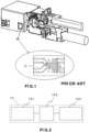
- a flexible PCB (Printed Circuit Board) 33 is used for data signal transfer from jack contacts to single-pair contacts. Namely, in the inserted condition of the device, socket contacts of a standardized plug socket contact strip conductors on the flexible PCB 33. Thus, the flexible strip conductors function as adapter contacts.
- the fact that the PCB is flexible generates instability in the position, that is to say the orientation in space, as well as in the location of the contacts, which may result in lack of reliability of the connection and performance decrease.
- such adapter has several outer parts, carrying data signals where high currents flow. Outer parts are exposed to degradation, which may be detrimental to the quality of the connection and may even cause data transmission failure, not to mention the risk of injury for an operator or user.
- Document EP 2 649 686 A1 discloses a multipolar outlet for a conductor connector system.
- the present invention aims at remedying at least some of the above-mentioned deficiencies of the prior art.
- a data transmission connector comprising:
- the connector according to the invention not only is the connector according to the invention not specific to connections involving contacts lying next to each other, but in addition, it suppresses the need for an intermediate, flexible part.
- the plug contacts are rigid i.e. not flexible and they are fixed within the connector, which, as a result, forms a robust single part adapter.
- the connector according to the invention is an adapter that is particularly appropriate for splitting i.e. sharing data transfer plug contacts between two different connectors. This is because, in particular, due to the fixed arrangement of the data transfer plug contacts inside the connector, the latter provides a stable constellation of data transfer plug contacts, which guarantees reliability, high performance and repeatability of data transmission end-to-end and, more generally, high quality and performance of the connection.
- the contact holder makes it possible to further ensure that the data transfer plug contacts stay in a fixed position and location inside the connector, for optimal quality and performance of the connection.
- the contact holder cover further contributes to maintaining the data transfer plug contacts in their desired fixed position and location inside the connector.
- the structure of the contact holder cover makes the contact holder cover modular. Such modularity makes it possible to ensure precise installation of each pair of data transfer plug contacts in its respective location inside the connector, as well as reinforced individual holding of each pair of data transfer plug contacts in position.
- the connector according to the invention may further comprise a contact separator.
- That element of the connector facilitates splitting of the connections.
- the contact separator may be made of metal.
- Such material is particularly appropriate for reaching an optimized cost/durability/robustness and shielding efficiency compromise for the contact separator.
- the connector may further comprise a latch.
- the housing of the data transmission connector according to the invention may be made of metal.
- Such material is particularly appropriate for reaching an optimized cost/durability/robustness and shielding efficiency compromise for the connector.
- the connector according to the invention is an 8-way connector.
- the connector according to the invention may be an adapter compliant with standard IEC-60603-7-7:2010 published by IEC on May 1, 2010 .
- the invention also provides a connector assembly, comprising:
- the first connector may be compliant with a predetermined standard.
- a connector assembly 10 according to a particular embodiment of the present invention comprises a first connector 101, a second connector 102 and a third connector 103.
- the first connector 101 is a data transmission connector having four pairs of connection ports.
- the first connector 101 may be a standardized connector i.e. it may be compliant with a predetermined standard.
- the second connector 102 is a single-pair data transmission connector having four single-pair connection ports distant from each other, i.e. not lying next to one another. Each of the single-pair connection ports comprises one pair of connection ports.
- the third connector 103 is a data transmission connector which has the functions of an adapter, connecting the first and second connectors 101, 102 in a manner described in more detail below.
- the data transmission connector according to the invention which is the third connector 103 in Figure 2 , will also be referred to as an adapter.
- the data transmission connector 103 comprises a housing 30.
- the housing 30 is preferably, but not necessarily, made of metal, for optimizing the quality to cost ratio. Metal will offer satisfying durability, robustness and shielding efficiency. A large variety of metallic materials may be used.
- the housing 30 may be made of aluminum and/or copper.
- zamac which is a zinc, aluminum, magnesium and copper alloy.
- the data transmission connector 103 also comprises a plurality of data transfer plug contacts 32.
- the data transfer plug contacts 32 are rigid. In other words, they are not flexible. This makes them more solid and resistant to damage.
- the data transfer plug contacts 32 are arranged fixedly inside the data transmission connector 103, as described in more detail below.
- the data transfer plug contacts 32 are accommodated inside the data transmission connector 103, they are not exposed to outer environment, which reduces even more the risk of damage to the data transfer plug contacts 32 and to the connection to be realized.
- the data transmission connector 103 further comprises a contact separator 38.
- the contact separator 38 is accommodated inside the housing 30.
- Each group comprises a predetermined number of data transfer plug contacts 32, as needed in the concerned connection.
- Each group is distant from another group i.e. is not lying next to another group.
- the data transfer plug contacts 32 of a given group are distant from the data transfer plug contacts 32 of another given group.
- the data transfer plug contacts 32 of that group are also distant from each other i.e. are not laying next to one another.
- each compartment 380 receives a pair of data transfer plug contacts 32 and thus separates the four pairs of data transfer plug contacts 32 from each other.
- the data transmission connector 103 is therefore an 8-way connector, but this is a non-limiting example.
- the contact separator 38 is preferably, but not necessarily, made of metal, for optimizing the quality to cost ratio. Metal will offer satisfying durability, robustness and shielding efficiency. A large variety of metallic materials may be used.
- the contact separator 38 may be made of aluminum and/or copper.
- zamac which is a zinc, aluminum, magnesium and copper alloy.
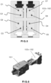
- the data transmission connector 103 further comprises a contact holder 34, accommodated inside the housing 30 and inserted in the contact separator 38.
- the contact separator 38 and the contact holder 34 may have side walls provided with respective complementary shapes, such as ribs and grooves, as shown in Figure 3 , through which they can slide with respect to each other during assembling. This enables insertion of the contact holder 34 into the contact separator 38 in a well-defined position.
- the contact holder 34 further has contact holder grooves 340, receiving the data transfer plug contact pairs 32.
- the shape of a given contact holder groove 340 generally corresponds to the shape of the data transfer plug contact pair 32 received in that contact holder groove 340.
- the contact holder 34 may be made of a single part. Alternatively, it may comprise several parts for modularity, which may facilitate mounting of the data transmission connector 103.
- the contact holder 34 further comprises a contact holder cover 36.
- the contact holder cover 36 comprises a plurality of contact holder cover parts 36P, each part 36P covering respectively one pair of data transfer plug contacts 32 of the plurality of data transfer plug contacts 32.
- two adjacent contact holder cover parts 36P may be provided with complementary shapes, fitting into each other.
- they may be assembled with each other through any means, such as screws or glue.
- contact holder cover parts 36P may further be provided with a predetermined number of pins 362, inserted in corresponding holes 364 provided in the contact holder 34.
- each contact holder cover part 36P (only the four pins 362 provided on the two bottom contact holder cover parts 36P are visible) and eight corresponding holes 364 are provided on the contact holder 34 (only the four holes 364 respectively receiving the four pins 362 provided on the two top contact holder cover parts 36P are visible).
- each contact holder cover part 36P may have contact holder cover grooves 360 receiving the data transfer plug contact pairs 32 for holding them in position.
- the shape of a contact holder cover groove 360 generally corresponds to the shape of the data transfer plug contact pair 32 received in that contact holder cover groove 360.
- the data transmission connector 103 may optionally further comprise a latch 40, fitting for example into the back side of the housing 30, that is to say the side of the data transmission connector 103 opposite to the contact separator 38.
- each of the data transfer plug contact pairs 32 are adjacent on a first predetermined length of the contact pair and split so as to be distant from each other and oriented in a predetermined manner on a second predetermined length of the same contact pair, so as to be arranged as described below in more detail with reference to Figure 5 .
- Figure 4 schematically illustrates part of the data transmission connector 103, with one of four single-pair connections of the single-pair connector 102 inserted therein and the three other single-pair connections of the single-pair connector 102 not inserted, for better legibility of the drawing and for facilitating understanding of the invention.
- FIG. 5 A non-limiting example of the arrangement of the data transfer plug contacts 32 is illustrated by Figure 5 , in a particular embodiment where there are eight data transfer plug contacts 32, designated by reference signs C1 to C8.
- Figure 5 is a schematic front view of the parts of the data transmission connector 103 and of the single-pair connector 102 shown in Figure 4 . More particularly, Figure 5 illustrates the fixed, well-defined positioning, location and separation of the data transfer plug contacts 32, which are separated in four groups, each group comprising a pair of data transfer plug contacts 32, as follows:
- the data transfer plug contacts 32 are arranged in the four corners of the adapter 103.
- the connector 103 may be used for example in the field of structured cabling systems.
- a structured cabling system is a complete system of cabling and associated hardware, which provides a comprehensive telecommunications infrastructure.
- Such infrastructure is usually not device dependent and serves a wide range of uses, such as telephony or data transmission through a computer network.
- Structured cabling design and installation is governed by a set of standards that specify wiring data centers, offices, and apartment buildings for data or voice communications using various kinds of cables, fiber optic cabling, modular connectors, etc.
- the invention may be used in such a structured cabling system, when for example a standardized four-pair link is needed.
- a single-pair Ethernet telecommunications network is one among many other fields of application of the invention.
- the data transmission connector 103 may be used with standardized connectors of the Cat7, GG45 type and with standardized connectors of the Cat7-only connector, as an adapter compliant with standard IEC-60603-7-7:2010 published by IEC (International Electrotechnical Commission) on May 1, 2010 , such as an IEC-60603-7-7:2010 front-end adapter.
- An electric cable may comprise at least one connector assembly 10 as described above.
- the electric cable may be an Ethernet cable.
- Such an Ethernet electric cable may be used in PoE (Power over Ethernet) data transmission over a telecommunications network.
- PoE Power over Ethernet
Landscapes
- Details Of Connecting Devices For Male And Female Coupling (AREA)
Claims (9)
- Connecteur de transmission de données (103), comprenant :un boîtier (30) ;une pluralité de contacts à fiche de transfert de données (32) qui sont rigides et sont agencés fixement à l'intérieur dudit connecteur (103) ;un porte-contacts (34) comprenant un couvercle de porte-contacts (36) ; caractérisé en ce que ledit couvercle de porte contacts (36) comprend une pluralité de pièces de couvercle de porte-contacts qui sont mécaniquement assemblées les unes aux autres, chaque pièce (36P) de ladite pluralité de pièces de couvercle de porte-contacts couvrant respectivement une paire de contacts à fiche de transfert de données (32) de ladite pluralité de contacts à fiche de transfert de données (32).
- Connecteur (103) selon la revendication 1, caractérisé en ce qu'il comprend en outre un séparateur de contacts (38).
- Connecteur (103) selon la revendication 2, caractérisé en ce que ledit séparateur de contacts (38) est en métal.
- Connecteur (103) selon l'une quelconque des revendications précédentes, caractérisé en ce qu'il comprend en outre un verrou (40).
- Connecteur (103) selon l'une quelconque des revendications précédentes, caractérisé en ce que ledit boîtier (30) est en métal.
- Connecteur (103) selon l'une quelconque des revendications précédentes, caractérisé en ce qu'il est un connecteur à huit voies.
- Connecteur (103) selon l'une quelconque des revendications précédentes, caractérisé en ce qu'il est un adaptateur conforme à la norme IEC-60603-7-7 : 2010 publiée par l'IEC le 1er mai 2010.
- Ensemble de connecteurs (10), comprenant :un premier connecteur de transmission de données (101), ayant quatre paires de ports de connexion ;un deuxième connecteur de transmission de données (102), ayant quatre ports de connexion à paire unique distants les uns des autres et comprenant chacun une paire de ports de connexion ; etun troisième connecteur de transmission de données, connectant lesdits premier et deuxième connecteurs (101, 102) ;ledit ensemble de connecteurs (10) étant caractérisé en ce que ledit troisième connecteur (103) est selon l'une quelconque des revendications précédentes.
- Ensemble de connecteurs (10) selon la revendication 8, caractérisé en ce que ledit premier connecteur (101) est conforme à une norme prédéterminée.
Priority Applications (2)
| Application Number | Priority Date | Filing Date | Title |
|---|---|---|---|
| EP20305570.2A EP3916929B1 (fr) | 2020-05-29 | 2020-05-29 | Connecteur de transmission de données et ensemble de connecteurs correspondant, câble électrique et son utilisation |
| US17/327,303 US11502446B2 (en) | 2020-05-29 | 2021-05-21 | Data transmission connector and a corresponding connector assembly, electric cable and use thereof |
Applications Claiming Priority (1)
| Application Number | Priority Date | Filing Date | Title |
|---|---|---|---|
| EP20305570.2A EP3916929B1 (fr) | 2020-05-29 | 2020-05-29 | Connecteur de transmission de données et ensemble de connecteurs correspondant, câble électrique et son utilisation |
Publications (2)
| Publication Number | Publication Date |
|---|---|
| EP3916929A1 EP3916929A1 (fr) | 2021-12-01 |
| EP3916929B1 true EP3916929B1 (fr) | 2024-03-20 |
Family
ID=71465266
Family Applications (1)
| Application Number | Title | Priority Date | Filing Date |
|---|---|---|---|
| EP20305570.2A Active EP3916929B1 (fr) | 2020-05-29 | 2020-05-29 | Connecteur de transmission de données et ensemble de connecteurs correspondant, câble électrique et son utilisation |
Country Status (2)
| Country | Link |
|---|---|
| US (1) | US11502446B2 (fr) |
| EP (1) | EP3916929B1 (fr) |
Families Citing this family (1)
| Publication number | Priority date | Publication date | Assignee | Title |
|---|---|---|---|---|
| WO2023147663A1 (fr) * | 2022-02-01 | 2023-08-10 | Belden Canada Ulc | Connecteur ethernet à paire simple (spe) et système |
Citations (1)
| Publication number | Priority date | Publication date | Assignee | Title |
|---|---|---|---|---|
| EP2649686B1 (fr) * | 2010-12-06 | 2016-01-27 | BKS Engineering AG | Sortie multipolaire pour système de raccordement conducteur |
Family Cites Families (6)
| Publication number | Priority date | Publication date | Assignee | Title |
|---|---|---|---|---|
| US6988914B2 (en) * | 2003-03-14 | 2006-01-24 | Tyco Electronics Corporation | Electrical coupler with splitting receptacle jack interfaces |
| US7025636B2 (en) * | 2004-08-26 | 2006-04-11 | George Allen | Adaptor for making broken connectors serviceable |
| AU2007291879B2 (en) | 2006-09-01 | 2011-07-28 | Reichle & De-Massari Ag | Adapter and plug-in connection system |
| US7744414B2 (en) * | 2008-07-08 | 2010-06-29 | 3M Innovative Properties Company | Carrier assembly and system configured to commonly ground a header |
| WO2011094656A2 (fr) * | 2010-02-01 | 2011-08-04 | 3M Innovative Properties Company | Connecteur électrique et ensemble |
| US9033725B2 (en) * | 2012-04-19 | 2015-05-19 | Panduit Corp. | GG45 plug with hinging load bar |
-
2020
- 2020-05-29 EP EP20305570.2A patent/EP3916929B1/fr active Active
-
2021
- 2021-05-21 US US17/327,303 patent/US11502446B2/en active Active
Patent Citations (1)
| Publication number | Priority date | Publication date | Assignee | Title |
|---|---|---|---|---|
| EP2649686B1 (fr) * | 2010-12-06 | 2016-01-27 | BKS Engineering AG | Sortie multipolaire pour système de raccordement conducteur |
Also Published As
| Publication number | Publication date |
|---|---|
| US20210376518A1 (en) | 2021-12-02 |
| US11502446B2 (en) | 2022-11-15 |
| EP3916929A1 (fr) | 2021-12-01 |
Similar Documents
| Publication | Publication Date | Title |
|---|---|---|
| US7316584B2 (en) | Matched impedance shielded pair interconnection system for high reliability applications | |
| EP2224545B1 (fr) | Cassette pour système d'interconnexion de câbles | |
| US9876322B2 (en) | Backward compatible connectivity for high data rate applications | |
| US7909622B2 (en) | Shielded cassette for a cable interconnect system | |
| EP2524417B1 (fr) | Ensemble de connecteur | |
| US7524211B2 (en) | Digital switching cross-connect module | |
| US4634209A (en) | Modular plug connector | |
| EP0551768A1 (fr) | Dispositif de câblage pour circuit de distribution | |
| EP2410620B1 (fr) | Pince de câble pour ensemble connecteur | |
| EP2768086A1 (fr) | Connecteurs électriques disposant de paires différentielles | |
| WO2008127543A1 (fr) | Systèmes d'interconnexion à éléments connecteurs équilibrés à auto-compensation | |
| WO2004039091A2 (fr) | Systeme de correction haute densite | |
| US6296518B1 (en) | Stacked electrical connector assembly | |
| US5340333A (en) | Shielded modular adapter | |
| US20100221950A1 (en) | Shielded cassette for a cable interconnect system | |
| EP3916929B1 (fr) | Connecteur de transmission de données et ensemble de connecteurs correspondant, câble électrique et son utilisation | |
| US11888255B2 (en) | Single pair ethernet connector | |
| US6246749B1 (en) | Network interface unit and module | |
| EP2224546B1 (fr) | Cassette dotée de connecteurs d'accouplement à l'arrière interchangeables | |
| EP3284147B1 (fr) | Prise pour une unité de distribution d'alimentation à densité de sortie élevée | |
| CN114156683A (zh) | 与对接连接器、特别是印制电路板连接器接触的模块化连接器 | |
| GB2383475A (en) | Impedance matching cable connector |
Legal Events
| Date | Code | Title | Description |
|---|---|---|---|
| PUAI | Public reference made under article 153(3) epc to a published international application that has entered the european phase |
Free format text: ORIGINAL CODE: 0009012 |
|
| STAA | Information on the status of an ep patent application or granted ep patent |
Free format text: STATUS: THE APPLICATION HAS BEEN PUBLISHED |
|
| AK | Designated contracting states |
Kind code of ref document: A1 Designated state(s): AL AT BE BG CH CY CZ DE DK EE ES FI FR GB GR HR HU IE IS IT LI LT LU LV MC MK MT NL NO PL PT RO RS SE SI SK SM TR |
|
| B565 | Issuance of search results under rule 164(2) epc |
Effective date: 20201110 |
|
| STAA | Information on the status of an ep patent application or granted ep patent |
Free format text: STATUS: REQUEST FOR EXAMINATION WAS MADE |
|
| 17P | Request for examination filed |
Effective date: 20220601 |
|
| RBV | Designated contracting states (corrected) |
Designated state(s): AL AT BE BG CH CY CZ DE DK EE ES FI FR GB GR HR HU IE IS IT LI LT LU LV MC MK MT NL NO PL PT RO RS SE SI SK SM TR |
|
| GRAP | Despatch of communication of intention to grant a patent |
Free format text: ORIGINAL CODE: EPIDOSNIGR1 |
|
| STAA | Information on the status of an ep patent application or granted ep patent |
Free format text: STATUS: GRANT OF PATENT IS INTENDED |
|
| RIC1 | Information provided on ipc code assigned before grant |
Ipc: H01R 24/64 20110101ALN20230914BHEP Ipc: H01R 13/518 20060101ALI20230914BHEP Ipc: H01R 31/06 20060101ALI20230914BHEP Ipc: H01R 13/514 20060101AFI20230914BHEP |
|
| INTG | Intention to grant announced |
Effective date: 20231010 |
|
| GRAS | Grant fee paid |
Free format text: ORIGINAL CODE: EPIDOSNIGR3 |
|
| GRAA | (expected) grant |
Free format text: ORIGINAL CODE: 0009210 |
|
| STAA | Information on the status of an ep patent application or granted ep patent |
Free format text: STATUS: THE PATENT HAS BEEN GRANTED |
|
| AK | Designated contracting states |
Kind code of ref document: B1 Designated state(s): AL AT BE BG CH CY CZ DE DK EE ES FI FR GB GR HR HU IE IS IT LI LT LU LV MC MK MT NL NO PL PT RO RS SE SI SK SM TR |
|
| REG | Reference to a national code |
Ref country code: GB Ref legal event code: FG4D |
|
| REG | Reference to a national code |
Ref country code: CH Ref legal event code: EP |
|
| REG | Reference to a national code |
Ref country code: DE Ref legal event code: R096 Ref document number: 602020027471 Country of ref document: DE |
|
| REG | Reference to a national code |
Ref country code: IE Ref legal event code: FG4D |