EP3916675B1 - Bildverarbeitungssystem und kamerasystem - Google Patents
Bildverarbeitungssystem und kamerasystem Download PDFInfo
- Publication number
- EP3916675B1 EP3916675B1 EP19912034.6A EP19912034A EP3916675B1 EP 3916675 B1 EP3916675 B1 EP 3916675B1 EP 19912034 A EP19912034 A EP 19912034A EP 3916675 B1 EP3916675 B1 EP 3916675B1
- Authority
- EP
- European Patent Office
- Prior art keywords
- image
- original image
- luminance
- original
- unit
- Prior art date
- Legal status (The legal status is an assumption and is not a legal conclusion. Google has not performed a legal analysis and makes no representation as to the accuracy of the status listed.)
- Active
Links
Images




Classifications
-
- G—PHYSICS
- G06—COMPUTING OR CALCULATING; COUNTING
- G06T—IMAGE DATA PROCESSING OR GENERATION, IN GENERAL
- G06T7/00—Image analysis
- G06T7/20—Analysis of motion
- G06T7/254—Analysis of motion involving subtraction of images
-
- H—ELECTRICITY
- H04—ELECTRIC COMMUNICATION TECHNIQUE
- H04N—PICTORIAL COMMUNICATION, e.g. TELEVISION
- H04N23/00—Cameras or camera modules comprising electronic image sensors; Control thereof
- H04N23/10—Cameras or camera modules comprising electronic image sensors; Control thereof for generating image signals from different wavelengths
-
- G—PHYSICS
- G06—COMPUTING OR CALCULATING; COUNTING
- G06T—IMAGE DATA PROCESSING OR GENERATION, IN GENERAL
- G06T5/00—Image enhancement or restoration
- G06T5/50—Image enhancement or restoration using two or more images, e.g. averaging or subtraction
-
- G—PHYSICS
- G06—COMPUTING OR CALCULATING; COUNTING
- G06T—IMAGE DATA PROCESSING OR GENERATION, IN GENERAL
- G06T5/00—Image enhancement or restoration
- G06T5/90—Dynamic range modification of images or parts thereof
- G06T5/92—Dynamic range modification of images or parts thereof based on global image properties
-
- H—ELECTRICITY
- H04—ELECTRIC COMMUNICATION TECHNIQUE
- H04N—PICTORIAL COMMUNICATION, e.g. TELEVISION
- H04N23/00—Cameras or camera modules comprising electronic image sensors; Control thereof
- H04N23/70—Circuitry for compensating brightness variation in the scene
- H04N23/71—Circuitry for evaluating the brightness variation
-
- H—ELECTRICITY
- H04—ELECTRIC COMMUNICATION TECHNIQUE
- H04N—PICTORIAL COMMUNICATION, e.g. TELEVISION
- H04N23/00—Cameras or camera modules comprising electronic image sensors; Control thereof
- H04N23/70—Circuitry for compensating brightness variation in the scene
- H04N23/73—Circuitry for compensating brightness variation in the scene by influencing the exposure time
-
- H—ELECTRICITY
- H04—ELECTRIC COMMUNICATION TECHNIQUE
- H04N—PICTORIAL COMMUNICATION, e.g. TELEVISION
- H04N23/00—Cameras or camera modules comprising electronic image sensors; Control thereof
- H04N23/70—Circuitry for compensating brightness variation in the scene
- H04N23/76—Circuitry for compensating brightness variation in the scene by influencing the image signals
-
- H—ELECTRICITY
- H04—ELECTRIC COMMUNICATION TECHNIQUE
- H04N—PICTORIAL COMMUNICATION, e.g. TELEVISION
- H04N5/00—Details of television systems
- H04N5/14—Picture signal circuitry for video frequency region
- H04N5/144—Movement detection
-
- G—PHYSICS
- G06—COMPUTING OR CALCULATING; COUNTING
- G06T—IMAGE DATA PROCESSING OR GENERATION, IN GENERAL
- G06T2207/00—Indexing scheme for image analysis or image enhancement
- G06T2207/10—Image acquisition modality
- G06T2207/10016—Video; Image sequence
Definitions
- the present invention relates to an image processing system and a camera system.
- the technique described in PTL 1 describes that "as processing means for tracking a moving object, there are background difference processing means and template matching processing means, and these two tasks of processing are appropriately switched based on an illumination variation detection result of a monitoring region by environment variation detection means and stability of a background image stored in a storage unit.”, "when the environment variation detection means detects an illumination variation in the monitoring region, tracking processing switching means continues tracking the moving object by switching tracking processing of the moving object from background difference processing to main template matching processing and compensates for illumination of an input image.”, and "in a background difference processing method, the stability of the extraction of the moving object is excellent, and a processing load is also small. However, when the input image is in an unstable state due to the illumination variation, the background difference processing cannot be performed.
- the template matching processing can be executed by compensating for the input image and obtaining an image of which a luminance value is approximated to an image before the change.
- the background difference processing even though the illumination compensation is performed, since the correction cannot be accurately performed in all pixels, even a region other than the moving object is extracted as a background difference region, and thus, it is difficult to perform the background difference processing.
- PTL 2 describes that "when a background image is recreated in response to an illuminance change, a luminance value of an image (P2 in FIG. 1(C)) in a region in which a background cannot be created due to being blocked by a moving object is estimated as a likely value of the background image to be used after the illuminance change by a conversion equation (converting the luminance value before the illuminance change into the value after the change) obtained as an approximate equation from a relationship between the luminance values of the same pixel position in both the background image before the illuminance change (FIG. 1(A)) and the captured image at the illuminance after the change (FIG. 1(B)), and is complemented with the obtained estimation value.”
- PTL 3 discloses an object extraction method in which an extraction target included in an input image is extracted from a difference image which can be obtained by differentiating the input image photographed by an image pickup device, in which the same background is made as an image pickup region, and the existing reference background image regarding a luminance value of each pixel.
- Techniques in the related art have problems that it is difficult to detect an object in a background difference type when an exposure condition of a camera changes.
- the background difference type is switched not to be used for object detection.
- the present invention has been made in view of the above problems, and an object of the present invention is to provide an image processing system and a camera system capable of appropriately detecting an object in a background difference type even when an exposure condition of a camera changes.
- the present specification includes the content disclosed in Japanese Patent Application No. 2019-009090 , which is a priority document of the present application.
- the object can be appropriately detected in the background difference type even though the exposure condition of the camera changes.
- the exposure condition of the camera changes.
- an in-vehicle camera that needs to be operated while changing the exposure condition can appropriately detect the moving object.
- a luminance value of a dark object may become zero, a luminance value of an object having a low contrast ratio may become uniform, or a contour, light and shade, and the like may not be discriminated.
- This problem is remarkable when the luminance value is expressed as a digital value, but the same problem may occur even when the luminance value is expressed as an analog value.
- a luminance value of the bright object becomes a maximum value, and a contour of the object or a gradation of the object may not be discriminated. Accordingly, it is necessary to set the exposure condition in accordance with the brightness of the object to be captured.
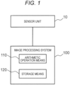
- the image processing system 100 has a configuration as a known computer, and includes arithmetic operation means 110 and storage means 120.
- the arithmetic operation means 110 includes, for example, a microprocessor
- the storage means 120 includes, for example, a semiconductor memory and a magnetic disk.
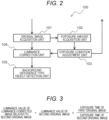
- FIG. 2 is a block diagram illustrating an example of a configuration of the image processing system 100.
- the arithmetic operation means 110 of the image processing system 100 functions as an original image acquisition unit 101, an exposure amount acquisition unit 102, an exposure condition adjustment unit 103, a luminance correction unit 104, and an object detection unit 105 by executing a program stored in the storage means 120 or another location.
- the original image acquisition unit 101 acquires an image from the sensor unit 10.
- the image is, for example, a shutter image of the camera.
- the image acquired here is an image before the adjustment and correction to be described below, and thus, the image is referred to as an "original image" below.
- the original image acquisition unit 101 can acquire a plurality of original images related to different times.
- the images related to different times are, for example, images related to different shutters or different shutter times from one imaging sensor. For example, when the sensor unit 10 continuously outputs a plurality of images representing a moving image, the original image acquisition unit 101 sequentially acquires these images.
- the exposure amount acquisition unit 102 acquires an exposure amount related to the original image acquired by the original image acquisition unit 101.
- the exposure amount is, for example, an amount indicating how much light the imaging sensor of the sensor unit 10 is exposed to in the same shutter.
- the expression form and acquisition method of the exposure amount can be appropriately designed by those skilled in the art based on a known technique.
- the exposure condition adjustment unit 103 transmits information indicating the adjusted exposure condition to the luminance correction unit 104.
- the exposure condition is associated with each original image, for example.
- the exposure condition adjustment unit 103 instructs the sensor unit 10 to set the exposure condition to a certain value, and when a certain original image is captured under the exposure condition, the exposure condition is associated with the original image.
- the luminance correction unit 104 acquires the original image from the original image acquisition unit 101 and acquires the exposure condition related to the original image from the exposure condition adjustment unit 103.
- the luminance correction unit 104 changes the luminance value of the original image based on the exposure condition. A specific example of processing of changing the luminance value will be described below.
- the luminance correction unit 104 corrects a variation in sensitivity of the sensor unit 10 for each pixel.
- the luminance correction unit 104 corrects the variation based on sensitivity information regarding a light amount of each pixel of the imaging sensor stored in advance in the storage means 120.
- the sensitivity information is information indicating a relationship of whether a luminance value corresponds to a certain light amount.
- the storage means 120 stores the sensitivity information.
- the sensitivity information can be created by any method. For example, an object having uniform brightness is captured by the sensor unit 10 in advance, a luminance value of each pixel at this time is checked, and the sensitivity information can be generated based on the luminance value. In the capturing at this time, for example, a pure white low-reflection plate-like object is captured so as to spread over the entire field of view. Such sensitivity correction by the luminance correction unit 104 may be omitted. In this case, the creation of the sensitivity information can be omitted.
- the luminance correction unit 104 corrects the luminance value in accordance with the exposure conditions of the plurality of original images. For example, a new image is acquired by correcting the luminance value of the second original image such that a difference in the luminance value from the first original image decreases in accordance with the exposure condition related to the first original image and the exposure condition related to the second original image.
- the new image is referred to as a "luminance-corrected image”.
- the correction is performed such that the luminance values of the plurality of original images become values closer to each other.
- any one of the plurality of original images may be used as a reference (first original image), and the luminance value of the other original image (second original image) may be corrected to be close to the reference.
- the correction may be performed such that the luminance values coincide with each other, or the correction may be performed such that the luminance values become values within a range similar to each other.
- luminance value regarding a certain image can be appropriately decided by those skilled in the art.
- the luminance value of a specific pixel of a certain image may be used, or the luminance value of the image may be calculated by performing statistical processing (averaging or the like) on the luminance values of all the pixels.
- the exposure condition includes information indicating the exposure time
- the luminance value of the second original image is corrected to be low.
- the luminance value of the second original image is corrected to be high.
- the exposure condition includes information indicating the gain
- the luminance value of the second original image is corrected to be low.
- the luminance value of the second original image is corrected to be high.
- the original image captured first is the first original image and the original image captured later is the second original image to be corrected
- an anteroposterior relationship therebetween is arbitrary. That is, the luminance value may be corrected by using the original image captured later as the first original image (reference) and the original image captured first as the second original image.
- the ratio between the exposure times is multiplied in this manner, and thus, the difference in the luminance value can be more appropriately corrected.
- the luminance correction unit 104 transmits the luminance-corrected image to the object detection unit 105.
- the luminance correction unit 104 may omit the correction of the luminance value. In this case, the luminance correction unit 104 may directly transmit the original image to the object detection unit 105.
- the object detection unit 105 detects the object by acquiring a background difference based on the luminance-corrected image received from the luminance correction unit 104.
- a background difference based on the luminance-corrected image received from the luminance correction unit 104.
- the object is detected based on these two images.
- the specific processing in the background difference type can be appropriately designed by those skilled in the art, and an example will be described below.
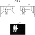
- FIG. 4 illustrates an object detection principle in the background difference type.
- the images of the plurality of shutters in a sequence of time are compared, and a pixel having a difference is output as a difference image.
- a difference image 203 is acquired based on a first original image 201 and a luminance-corrected image 202.
- the first original image 201 is a background image, and is an image in which the moving object does not appear.
- the luminance-corrected image 202 is a luminance-corrected image corresponding to the image of the latest shutter (second original image).
- a difference between the first original image 201 and the luminance-corrected image 202 is shown on the difference image 203.
- the moving object since the moving object is not included in the first original image 201 and the moving object is included in the luminance-corrected image, only the moving object can be detected as the difference on the difference image 203.
- a reference background image may be used by dividing the image into a plurality of regions, collecting the regions where there is no difference, and combining the images of the different shutters.
- Such a reference background image may be stored in advance in the storage means 120 and may be used as the first original image.
- the reference background image can be generated by combining the divided regions as described above.
- the difference image may be output by comparing the image related to the latest shutter (luminance-corrected image) with the image related to the shutter (first original image) at a time before the latest shutter.
- the moving object can be detected by comparing the image related to the latest shutter with the image related to the shutter at the time before the latest shutter.
- a background portion moves on the image.
- one or both of the images may be deformed, for example, like a case where one or both of the images is moved in parallel such that portions corresponding to the background overlap between the two images. In this manner, the difference in the background is suppressed, and thus, the difference can be acquired by focusing on the moving object.
- the object detection unit 105 may further specify and output a range of pixels in which the moving object is present in the difference image. For example, a plurality of pixels at close distances among the pixels representing the moving object may be collected into one set, and a range in which the set is present may be set as a range in which the mobile body is present.
- the correction of luminance when object detection processing is continuously performed over three or more images will be described with reference to FIG. 6 .
- the images are acquired at times T0, T1, T2, T3, T4, ..., and changes in an exposure time 401 and a luminance value 402 related to each image are shown. While time-series shutters are sequentially captured from time T0 to time T4, the exposure condition changes between time T2 and time T3, and the exposure time decreases from E1 to E2. Accordingly, the luminance value also decreases from B1 to B2.
- the luminance value is B1 and is constant until time T2, and the object can be correctly detected, but since the luminance value of the pixel of the entire image changes at time T3, the entire image is recognized as the object, and the object cannot be correctly detected.
- the correction is performed by the luminance correction unit 104.
- the image related to time T2 first original image
- the image related to time T3 second original image
- a luminance value is B1 on the luminance-corrected image.
- the object can be appropriately detected.
- FIG. 6 it is considered that the following equation is established using the mathematical expression of FIG. 3 .
- B 1 B 2 ⁇ E 1 / E 2
- the image processing system 100 may have a function of performing geometric transformation on the image.
- aerial view conversion may be performed on the image.
- conversion may be performed such that the road surface is parallel to an image plane.
- the moving object may be, for example, a pedestrian or a vehicle.
- the image processing system 100 may further have a function of detecting the object regardless of the background difference type. That is, the image processing system 100 may include a non-background difference type object detection unit that detects an object based on any of the original images without acquiring the background difference.
- the non-background difference type object detection unit may be an object detection unit different from the background difference type object detection unit. In such a detection type, not only the moving object but also the object can be detected, and for example, a three-dimensional object can also be detected.
- the object can be appropriately detected in the background difference type even though the exposure condition of the camera changes.
- the exposure condition of the camera changes.
- the number of imaging units in the sensor unit 10 is not particularly limited.
- the sensor unit is limited to a configuration including a plurality of imaging units.
- FIG. 7 is a block diagram illustrating an example of a configuration of a camera system according to the present embodiment.
- the camera system includes a sensor unit 11 and an image processing system 500.
- the sensor unit 11 includes a left imaging unit 12 and a right imaging unit 13, and is, for example, a known stereo camera.
- the left imaging unit 12 and the right imaging unit 13 are arranged at different positions to cause parallax.
- a hardware configuration of the image processing system 500 is similar to that of the first embodiment.
- the left imaging unit 12 images a left field of view region 14, and the right imaging unit 13 images a right field of view region 15.
- the left field of view region 14 and the right field of view region 15 partially overlap and are shifted from each other on the left and right.
- the original image includes a stereo region R1, a left monocular region R2, and a right monocular region R3.
- the stereo region is a region in which an angle of view of the original image related to the left imaging unit 12 and an angle of view of the original image related to the right imaging unit 13 overlap with each other.
- the monocular region is a region in which the angles of view do not overlap between the original image related to the left imaging unit 12 and the original image related to the right imaging unit 13.
- the stereo region R1, the left monocular region R2, and the right monocular region R3 do not overlap each other.
- the image processing system 500 performs stereo matching type object detection in the stereo region R1, and performs background difference type object detection in the left monocular region R2 and the right monocular region R3.
- background difference type object detection an aerial view image obtained by performing projective transformation on the road surface may be used. Background difference processing using the aerial view image is referred to as aerial view difference processing.
- FIG. 9 is a block diagram illustrating an example of a configuration of the image processing system 500 according to the second embodiment.
- Arithmetic operation means of the image processing system functions as an original image acquisition unit 501, an exposure amount acquisition unit 502, an exposure condition adjustment unit 503, a luminance correction unit 504, a background difference type object detection unit 505, and a parallax type object detection unit 506 by executing a program stored in the storage means or another location.
- the parallax type object detection unit 506 is an example of the non-background difference type object detection unit that detects the object without acquiring the background difference.
- the parallax type object detection unit 506 may be an object detection unit different from the background difference type object detection unit 505.
- the original image acquisition unit 501 acquires an image from the sensor unit 11.
- a plurality of original images related to different positions can be acquired from the left imaging unit 12 and the right imaging unit 13. More precisely, a first original image and a second original image can be obtained for a plurality of different positions, respectively.
- a first original image and a second original image related to different shutters or different shutter times from the left imaging unit 12 are acquired, and a first original image and a second original image related to different shutters or different shutter times from the right imaging unit 13 are acquired.
- Operations of the exposure amount acquisition unit 502, the exposure condition adjustment unit 503, and the background difference type object detection unit 505 are similar to those of the exposure amount acquisition unit 102, the exposure condition adjustment unit 103, and the object detection unit 105 of the first embodiment, respectively.
- the conversion at this time is performed so as to correspond to a plurality of original images related to the same position. That is, the luminance correction unit 504 corrects a luminance value of the second original image from the left imaging unit 12 such that a difference in the luminance value from the first original image from the left imaging unit 12 decreases, and corrects a luminance value of the second original image from the right imaging unit 13 such that a difference in luminance value from the first original image from the right imaging unit 13 decreases.
- the luminance correction unit 504 executes predetermined conversion in relation to the luminance correction processing described in the first embodiment.
- This conversion can be performed, for example, as a bitwise operation.
- the luminance correction unit 504 converts a luminance value of the original image represented by a predetermined number of initial bits (for example, luminance values of all pixels) into a luminance value having the same number of bits as the number of initial bits or a luminance value having the number of bits smaller than the number of initial bits in accordance with the conversion coefficient.
- This conversion may be, for example, an arithmetic operation of shifting bits by the number of bits corresponding to the conversion coefficient, an arithmetic operation of extracting only bits corresponding to the conversion coefficient among the bits and discarding other bits, or an arithmetic operation combining thereof.
- this conversion can also be performed by using a conversion table stored in advance in the storage means.
- the conversion table associates different output values with input values of the luminance values in accordance with the conversion coefficient.
- FIG. 10(A) is an example of a data format of the luminance value before the bitwise operation.
- the luminance value before the bitwise operation is represented by 12 bits.
- FIGS. 10(B) and 10(C) are examples of a data format of the luminance value after the bitwise operation. In this example, the luminance value after the bitwise operation is represented by 8 bits.
- FIGS. 10(B) and 10(C) after the data of FIG. 10(A) is bit-shifted to the LSB side, the number of bits is reduced by discarding specific bits.
- the amount of bit shifts changes in accordance with the conversion coefficient. For example, when the exposure condition of the first original image and the exposure condition of the second original image are greatly different from each other, the conversion coefficient increases. In this case, the amount of bit shifts changes such that a difference between the number of bits of the bit shift with respect to the first original image and the number of bits of the bit shift with respect to the second original image increases. Conversely, when the exposure condition of the first original image and the exposure condition of the second original image are equal or are hardly different, the conversion coefficient becomes zero or decreases. In this case, the amount of the bit shifts changes such that the number of bits of the bit shift with respect to the first original image and the number of bits of the bit shift with respect to the second original image are equal to each other or the difference decreases.
- the luminance correction unit 504 bit-shifts the luminance value of the second original image in accordance with the exposure condition related to the first original image and the exposure condition related to the second original image when the luminance value of the second original image is corrected. Furthermore, it can be said that the arithmetic operation related to the multiplication is executed by bit-shifting of the luminance value of the second original image in accordance with the exposure condition related to the first original image and the exposure condition related to the second original image when the luminance correction unit 504 executes the multiplication illustrated in FIG. 3 .
- the processing of FIG. 10 can also be interpreted as an arithmetic operation for reducing the number of bits.
- the bits 0 and 9 to 11 are discarded and the number of bits is reduced
- the bits 8 to 11 are discarded and the number of bits is reduced.
- the luminance correction unit 504 reduces the number of bits of the luminance value of the second original image in accordance with the exposure condition related to the first original image and the exposure condition related to the second original image when the luminance value of the second original image is corrected.
- the arithmetic operation related to the multiplication is executed by reducing the number of bits of the luminance value of the second original image in accordance with the exposure condition related to the first original image and the exposure condition related to the second original image when the luminance correction unit 504 executes the multiplication illustrated in FIG. 3 .
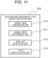
- the background difference type object detection unit 505 detects the object by acquiring the background difference based on the image output from the luminance correction unit 504. Furthermore, the parallax type object detection unit 506 detects the object by acquiring parallax based on the image output from the original image acquisition unit 501. Specific contents of processing of these detection units can be appropriately designed by those skilled in the art, and examples thereof will be described below.
- the aerial view conversion unit 510 converts the image output from the luminance correction unit 504 into an aerial view image projected on the road surface while correcting distortion of the lens.
- the aerial view difference unit 511 acquires a difference between aerial view images of preceding and following shutters.
- the pixel set detection unit 512 detects, as the object (for example, a three-dimensional object or a moving object), a set of pixels having the difference.
- the type identification unit 513 identifies a type of the object such as a pedestrian or a vehicle.
- FIG. 12 is a block diagram illustrating an example of a more detailed configuration of the parallax type object detection unit 506.
- the parallax type object detection unit 506 includes a geometric correction unit 520, a stereo matching unit 521, a pixel set detection unit 522, and a type identification unit 523.
- the geometric correction unit 520 corrects distortion at the time of capturing in the sensor unit 11.
- the correction is performed based on distortion information of each of the left imaging unit 12 and the right imaging unit 13.
- This distortion information is retained in the storage means as a calibration table indicating a position of image coordinates before distortion correction for each pixel in an image coordinate system after distortion correction.
- the stereo matching unit 521 specifies a parallax value between corresponding pixels by comparing both left and right images corrected by the geometric correction unit 520.
- the "corresponding pixels" are pixels in which the same object appears.
- the parallax value is, for example, 3.2 when the corresponding pixels are shifted by 3.2 pixels on the left and right.
- a method for searching for a position at which a value of the sum of absolute differences (SAD) of absolute values of differences in luminance values is the smallest by using a region of a plurality of pixels as a template is used.
- the pixel set detection unit 522 detects the object (for example, a three-dimensional object or a moving object) by specifying a set of pixels of the same object based on the parallax value of each pixel output by the stereo matching unit 521. Since the same object is present at the same distance, one set is constituted by a plurality of pixels having close parallax values, and this set represents the object.
- the type identification unit 523 identifies the type of the object detected by the pixel set detection unit 522. The type is, for example, a vehicle or a pedestrian.
- the object can be appropriately detected in the background difference type even though the exposure condition of the camera changes as in the first embodiment.
- it is possible to appropriately detect the moving object.
- the parallax type object detection unit other than the background difference type is provided, and in particular, the parallax type object detection unit 506 detects the object by using the image in a state in which the luminance correction by the luminance correction unit 504 is not performed.
- the exposure condition adjustment unit 503 can be configured to decide the exposure condition based on the stereo region of each original image.
- the luminance correction unit 504 can be configured to correct the luminance based on the monocular region of each original image.
- the luminance correction unit 504 acquires the luminance-corrected image related to the left imaging unit 12 by correcting the luminance value of the second original image such that the difference in the luminance value in the left monocular region R2 from the first original image decreases for the first original image and the second original image related to the left imaging unit 12, and acquires the luminance-corrected image related to the right imaging unit 13 by correcting the luminance value of the second original image such that the difference in the luminance value in the right monocular region R3 from the first original image decreases for the first original image and the second original image related to the right imaging unit 13.
- the exposure condition adjustment unit can be omitted.
- the exposure condition may be adjusted by another mechanism or the like independent of the image processing system (for example, as a part of the function of the sensor unit).
- a part or all of the aforementioned configurations, functions, processing units, and processing means may be realized by hardware by being designed with an integrated circuit, for example.
- each of the aforementioned configurations and functions may be realized by software by interpreting and executing a program that realizes each function by the processor.
- Information of programs, tables, and files for realizing the functions can be stored in a recording device such as a memory, a hard disk, or a solid state drive (SSD), or a recording medium such as an IC card, or an SD card.
- control lines and information lines illustrated are considered to be necessary for the description, and not all the control lines and information lines in a product are necessarily illustrated. Almost all the configurations may be considered to be actually connected to each other.
Landscapes
- Engineering & Computer Science (AREA)
- Multimedia (AREA)
- Signal Processing (AREA)
- Physics & Mathematics (AREA)
- General Physics & Mathematics (AREA)
- Theoretical Computer Science (AREA)
- Computer Vision & Pattern Recognition (AREA)
- Studio Devices (AREA)
- Image Processing (AREA)
- Image Analysis (AREA)
Claims (9)
- Bildverarbeitungssystem (100, 500), das umfasst:eine Einheit zur Erfassung eines Originalbildes (101, 501), die ein erstes Originalbild und ein zweites Originalbild erfasst;eine Helligkeitskorrektureinheit (104, 504), die ein helligkeitskorrigiertes Bild durch Korrigieren eines Helligkeitswerts des zweiten Originalbildes erfasst, so dass ein Unterschied von einem Helligkeitswert des ersten Originalbildes in Übereinstimmung mit einer Belichtungsbedingung bezüglich jedes der Originalbilder abnimmt; undeine Einheit zur Detektion eines Objekts vom Hintergrundunterschiedstyp (105, 505), die ein Objekt durch Erfassen eines Hintergrundunterschieds anhand des helligkeitskorrigierten Bildes detektiert,wobei die Einheit zur Erfassung eines Originalbildes (101, 501) das erste Originalbild und das zweite Originalbild bezüglich mehrerer verschiedener Positionen erfasst,wobei jedes der Originalbilder einen Stereobereich und einen Monokularbereich enthält, wobei der Stereobereich ein Bereich ist, in dem sich Sichtwinkel zwischen den Originalbildern bezüglich der verschiedenen Positionen überdecken, und der Monokularbereich ein Bereich ist, in dem sich die Sichtwinkel zwischen den Originalbildern bezüglich mehrerer Positionen nicht überdecken,wobei das Bildverarbeitungssystem (100, 500) eine Belichtungsbedingungsanpassungseinheit (103, 503) enthält, die die Belichtungsbedingung anhand des Stereobereichs jedes der Originalbilder bestimmt, unddie Helligkeitskorrektureinheit (104, 504) das helligkeitskorrigierte Bild bezüglich einer Position durch Korrigieren des Helligkeitswerts des zweiten Originalbildes bezüglich der Position derart erfasst, dass ein Unterschied des Helligkeitswerts von dem ersten Originalbild bezüglich der Position in dem Monokularbereich bezüglich der Position abnimmt.
- Bildverarbeitungssystem (100, 500) nach Anspruch 1, wobei die Helligkeitskorrektureinheit (104, 504) den Helligkeitswert des zweiten Originalbildes in Übereinstimmung mit der Belichtungsbedingung bezüglich jedes der Originalbilder bitweise verschiebt.
- Bildverarbeitungssystem (100, 500) nach Anspruch 1, wobei die Helligkeitskorrektureinheit (104, 504) die Anzahl von Bits des Helligkeitswerts des zweiten Originalbildes in Übereinstimmung mit der Beleuchtungsbedingung bezüglich jedes der Originalbilder verringert.
- Bildverarbeitungssystem (100, 500) nach Anspruch 1, wobeidie Belichtungsbedingung Informationen enthält, die eine Belichtungszeit repräsentieren, unddie Helligkeitskorrektureinheit (104, 504) den Helligkeitswert des zweiten Originalbildes mit einem Verhältnis einer Belichtungszeit bezüglich des ersten Originalbildes zu einer Belichtungszeit bezüglich des zweiten Originalbildes multipliziert.
- Bildverarbeitungssystem (100, 500) nach Anspruch 4, wobei die Helligkeitskorrektureinheit (104, 504) eine arithmetische Operation bezüglich der Multiplikation durch bitweises Verschieben des Helligkeitswerts des zweiten Originalbildes in Übereinstimmung mit der Belichtungsbedingung bezüglich jedes der Originalbilder ausführt.
- Bildverarbeitungssystem (100, 500) nach Anspruch 4, wobei die Helligkeitskorrektureinheit (104, 504) die arithmetische Operation bezüglich der Multiplikation durch Verringern der Anzahl von Bits des Helligkeitswerts des zweiten Originalbildes in Übereinstimmung mit der Belichtungsbedingung bezüglich jedes der Originalbilder ausführt.
- Bildverarbeitungssystem (100, 500) nach Anspruch 1, das ferner eine Einheit zur Detektion eines Objekts, die nicht vom Hintergrundunterschiedstyp ist, (506) umfasst, die ein Objekt anhand eines der Originalbilder detektiert, ohne einen Hintergrundunterschied zu erfassen,
wobei die Einheit zur Detektion eines Objekts, die nicht vom Hintergrundunterschiedstyp ist, (506) eine Einheit zur Detektion eines Objekts ist, die von der Einheit zur Detektion eines Objekts vom Hintergrundunterschiedstyp (105, 505) verschieden ist. - Kamerasystem, das umfasst:das Bildverarbeitungssystem (100, 500) nach Anspruch 1; undeine Kamera (10),wobei das Originalbild ein Verschlussbild der Kamera ist.
- Kamerasystem, das umfasst:das Bildverarbeitungssystem (100, 500) nach Anspruch 1; undeine Stereokamera (11),wobei die Einheit zur Erfassung eines Originalbildes (101, 501) mehrere Originalbilder bezüglich verschiedener Zeiten erfasst,die durch mehrere Abbildungseinheiten (12, 13) in der Stereokamera aufgenommen werden, unddie Originalbilder Verschlussbilder der Abbildungseinheiten (12, 13) sind.
Applications Claiming Priority (2)
| Application Number | Priority Date | Filing Date | Title |
|---|---|---|---|
| JP2019009090A JP7193359B2 (ja) | 2019-01-23 | 2019-01-23 | 画像処理システムおよびカメラシステム |
| PCT/JP2019/047136 WO2020152997A1 (ja) | 2019-01-23 | 2019-12-03 | 画像処理システムおよびカメラシステム |
Publications (3)
| Publication Number | Publication Date |
|---|---|
| EP3916675A1 EP3916675A1 (de) | 2021-12-01 |
| EP3916675A4 EP3916675A4 (de) | 2022-10-26 |
| EP3916675B1 true EP3916675B1 (de) | 2025-05-14 |
Family
ID=71735495
Family Applications (1)
| Application Number | Title | Priority Date | Filing Date |
|---|---|---|---|
| EP19912034.6A Active EP3916675B1 (de) | 2019-01-23 | 2019-12-03 | Bildverarbeitungssystem und kamerasystem |
Country Status (3)
| Country | Link |
|---|---|
| EP (1) | EP3916675B1 (de) |
| JP (1) | JP7193359B2 (de) |
| WO (1) | WO2020152997A1 (de) |
Family Cites Families (3)
| Publication number | Priority date | Publication date | Assignee | Title |
|---|---|---|---|---|
| JP2004274325A (ja) | 2003-03-07 | 2004-09-30 | Fuji Heavy Ind Ltd | 撮像による物体抽出方法 |
| JP5999483B2 (ja) * | 2011-11-02 | 2016-09-28 | 株式会社リコー | 付着物検出装置および車載機器制御装置 |
| JP6936058B2 (ja) | 2017-06-28 | 2021-09-15 | 矢崎総業株式会社 | 吸熱体付き導体及び電池パック |
-
2019
- 2019-01-23 JP JP2019009090A patent/JP7193359B2/ja active Active
- 2019-12-03 WO PCT/JP2019/047136 patent/WO2020152997A1/ja not_active Ceased
- 2019-12-03 EP EP19912034.6A patent/EP3916675B1/de active Active
Also Published As
| Publication number | Publication date |
|---|---|
| WO2020152997A1 (ja) | 2020-07-30 |
| EP3916675A1 (de) | 2021-12-01 |
| JP7193359B2 (ja) | 2022-12-20 |
| JP2020119176A (ja) | 2020-08-06 |
| EP3916675A4 (de) | 2022-10-26 |
Similar Documents
| Publication | Publication Date | Title |
|---|---|---|
| US10542208B2 (en) | Systems and methods for synthesizing high resolution images using image deconvolution based on motion and depth information | |
| JP5980294B2 (ja) | データ処理装置、撮像装置、およびデータ処理方法 | |
| US9092875B2 (en) | Motion estimation apparatus, depth estimation apparatus, and motion estimation method | |
| US20100215260A1 (en) | Image processing apparatus, image processing method, and program | |
| US8441554B2 (en) | Image capturing apparatus capable of extracting subject region from captured image | |
| US9589339B2 (en) | Image processing apparatus and control method therefor | |
| US9888154B2 (en) | Information processing apparatus, method for processing information, and computer program | |
| US20190045127A1 (en) | Image pick-up apparatus and control method thereof | |
| JP2022039719A (ja) | 位置姿勢推定装置、位置姿勢推定方法及びプログラム | |
| JP6366739B2 (ja) | 画像処理装置、画像処理方法およびプログラム | |
| JP2017098884A (ja) | 移動検出装置、移動検出方法、及び、プログラム | |
| US10204400B2 (en) | Image processing apparatus, imaging apparatus, image processing method, and recording medium | |
| JP7838608B2 (ja) | 情報処理装置、情報処理方法及び情報処理プログラム | |
| JP2017097767A (ja) | 移動情報取得装置、移動情報取得方法、及び、プログラム | |
| JP5395650B2 (ja) | 被写体領域抽出装置およびその制御方法、被写体追跡装置、並びにプログラム | |
| JP6176073B2 (ja) | 撮影システム及びプログラム | |
| US20190167080A1 (en) | Endoscope system | |
| EP3916675B1 (de) | Bildverarbeitungssystem und kamerasystem | |
| CN105009561A (zh) | 摄像装置的异物信息检测装置以及异物信息检测方法 | |
| US12423833B2 (en) | Transmitter, receiver, and communication system | |
| KR101306780B1 (ko) | Hdr 영상 시스템에서 영상 간의 노출 정도를 보정하기 위한 장치 및 그 방법 | |
| JP6099973B2 (ja) | 被写体領域追跡装置、その制御方法及びプログラム | |
| JP2021111929A (ja) | 撮像装置、撮像装置の制御方法およびプログラム | |
| CN110913143A (zh) | 图像处理方法、装置、存储介质及电子设备 | |
| KR20200139321A (ko) | 이미지 센서 및 이를 포함하는 이미지 처리 시스템 |
Legal Events
| Date | Code | Title | Description |
|---|---|---|---|
| STAA | Information on the status of an ep patent application or granted ep patent |
Free format text: STATUS: THE INTERNATIONAL PUBLICATION HAS BEEN MADE |
|
| PUAI | Public reference made under article 153(3) epc to a published international application that has entered the european phase |
Free format text: ORIGINAL CODE: 0009012 |
|
| STAA | Information on the status of an ep patent application or granted ep patent |
Free format text: STATUS: REQUEST FOR EXAMINATION WAS MADE |
|
| 17P | Request for examination filed |
Effective date: 20210823 |
|
| AK | Designated contracting states |
Kind code of ref document: A1 Designated state(s): AL AT BE BG CH CY CZ DE DK EE ES FI FR GB GR HR HU IE IS IT LI LT LU LV MC MK MT NL NO PL PT RO RS SE SI SK SM TR |
|
| DAV | Request for validation of the european patent (deleted) | ||
| DAX | Request for extension of the european patent (deleted) | ||
| REG | Reference to a national code |
Ref legal event code: R079 Ref country code: DE Ref legal event code: R079 Ref document number: 602019070102 Country of ref document: DE Free format text: PREVIOUS MAIN CLASS: G06T0007194000 Ipc: G06T0007254000 |
|
| A4 | Supplementary search report drawn up and despatched |
Effective date: 20220922 |
|
| RIC1 | Information provided on ipc code assigned before grant |
Ipc: G06T 5/50 20060101ALI20220916BHEP Ipc: G06T 5/00 20060101ALI20220916BHEP Ipc: G06T 7/254 20170101AFI20220916BHEP |
|
| GRAP | Despatch of communication of intention to grant a patent |
Free format text: ORIGINAL CODE: EPIDOSNIGR1 |
|
| STAA | Information on the status of an ep patent application or granted ep patent |
Free format text: STATUS: GRANT OF PATENT IS INTENDED |
|
| INTG | Intention to grant announced |
Effective date: 20241213 |
|
| RAP3 | Party data changed (applicant data changed or rights of an application transferred) |
Owner name: HITACHI ASTEMO, LTD. |
|
| GRAS | Grant fee paid |
Free format text: ORIGINAL CODE: EPIDOSNIGR3 |
|
| GRAA | (expected) grant |
Free format text: ORIGINAL CODE: 0009210 |
|
| STAA | Information on the status of an ep patent application or granted ep patent |
Free format text: STATUS: THE PATENT HAS BEEN GRANTED |
|
| AK | Designated contracting states |
Kind code of ref document: B1 Designated state(s): AL AT BE BG CH CY CZ DE DK EE ES FI FR GB GR HR HU IE IS IT LI LT LU LV MC MK MT NL NO PL PT RO RS SE SI SK SM TR |
|
| REG | Reference to a national code |
Ref country code: GB Ref legal event code: FG4D |
|
| REG | Reference to a national code |
Ref country code: CH Ref legal event code: EP |
|
| REG | Reference to a national code |
Ref country code: DE Ref legal event code: R096 Ref document number: 602019070102 Country of ref document: DE |
|
| REG | Reference to a national code |
Ref country code: IE Ref legal event code: FG4D |
|
| REG | Reference to a national code |
Ref country code: NL Ref legal event code: MP Effective date: 20250514 |
|
| PG25 | Lapsed in a contracting state [announced via postgrant information from national office to epo] |
Ref country code: FI Free format text: LAPSE BECAUSE OF FAILURE TO SUBMIT A TRANSLATION OF THE DESCRIPTION OR TO PAY THE FEE WITHIN THE PRESCRIBED TIME-LIMIT Effective date: 20250514 Ref country code: PT Free format text: LAPSE BECAUSE OF FAILURE TO SUBMIT A TRANSLATION OF THE DESCRIPTION OR TO PAY THE FEE WITHIN THE PRESCRIBED TIME-LIMIT Effective date: 20250915 Ref country code: ES Free format text: LAPSE BECAUSE OF FAILURE TO SUBMIT A TRANSLATION OF THE DESCRIPTION OR TO PAY THE FEE WITHIN THE PRESCRIBED TIME-LIMIT Effective date: 20250514 |
|
| REG | Reference to a national code |
Ref country code: LT Ref legal event code: MG9D |
|
| PG25 | Lapsed in a contracting state [announced via postgrant information from national office to epo] |
Ref country code: NO Free format text: LAPSE BECAUSE OF FAILURE TO SUBMIT A TRANSLATION OF THE DESCRIPTION OR TO PAY THE FEE WITHIN THE PRESCRIBED TIME-LIMIT Effective date: 20250814 Ref country code: GR Free format text: LAPSE BECAUSE OF FAILURE TO SUBMIT A TRANSLATION OF THE DESCRIPTION OR TO PAY THE FEE WITHIN THE PRESCRIBED TIME-LIMIT Effective date: 20250815 |
|
| PG25 | Lapsed in a contracting state [announced via postgrant information from national office to epo] |
Ref country code: NL Free format text: LAPSE BECAUSE OF FAILURE TO SUBMIT A TRANSLATION OF THE DESCRIPTION OR TO PAY THE FEE WITHIN THE PRESCRIBED TIME-LIMIT Effective date: 20250514 Ref country code: PL Free format text: LAPSE BECAUSE OF FAILURE TO SUBMIT A TRANSLATION OF THE DESCRIPTION OR TO PAY THE FEE WITHIN THE PRESCRIBED TIME-LIMIT Effective date: 20250514 |
|
| REG | Reference to a national code |
Ref country code: AT Ref legal event code: MK05 Ref document number: 1795460 Country of ref document: AT Kind code of ref document: T Effective date: 20250514 |
|
| PG25 | Lapsed in a contracting state [announced via postgrant information from national office to epo] |
Ref country code: BG Free format text: LAPSE BECAUSE OF FAILURE TO SUBMIT A TRANSLATION OF THE DESCRIPTION OR TO PAY THE FEE WITHIN THE PRESCRIBED TIME-LIMIT Effective date: 20250514 |
|
| PG25 | Lapsed in a contracting state [announced via postgrant information from national office to epo] |
Ref country code: HR Free format text: LAPSE BECAUSE OF FAILURE TO SUBMIT A TRANSLATION OF THE DESCRIPTION OR TO PAY THE FEE WITHIN THE PRESCRIBED TIME-LIMIT Effective date: 20250514 |
|
| PG25 | Lapsed in a contracting state [announced via postgrant information from national office to epo] |
Ref country code: AT Free format text: LAPSE BECAUSE OF FAILURE TO SUBMIT A TRANSLATION OF THE DESCRIPTION OR TO PAY THE FEE WITHIN THE PRESCRIBED TIME-LIMIT Effective date: 20250514 |
|
| PG25 | Lapsed in a contracting state [announced via postgrant information from national office to epo] |
Ref country code: RS Free format text: LAPSE BECAUSE OF FAILURE TO SUBMIT A TRANSLATION OF THE DESCRIPTION OR TO PAY THE FEE WITHIN THE PRESCRIBED TIME-LIMIT Effective date: 20250814 |
|
| PG25 | Lapsed in a contracting state [announced via postgrant information from national office to epo] |
Ref country code: IS Free format text: LAPSE BECAUSE OF FAILURE TO SUBMIT A TRANSLATION OF THE DESCRIPTION OR TO PAY THE FEE WITHIN THE PRESCRIBED TIME-LIMIT Effective date: 20250914 |
|
| PG25 | Lapsed in a contracting state [announced via postgrant information from national office to epo] |
Ref country code: LV Free format text: LAPSE BECAUSE OF FAILURE TO SUBMIT A TRANSLATION OF THE DESCRIPTION OR TO PAY THE FEE WITHIN THE PRESCRIBED TIME-LIMIT Effective date: 20250514 |
|
| PG25 | Lapsed in a contracting state [announced via postgrant information from national office to epo] |
Ref country code: DK Free format text: LAPSE BECAUSE OF FAILURE TO SUBMIT A TRANSLATION OF THE DESCRIPTION OR TO PAY THE FEE WITHIN THE PRESCRIBED TIME-LIMIT Effective date: 20250514 Ref country code: SM Free format text: LAPSE BECAUSE OF FAILURE TO SUBMIT A TRANSLATION OF THE DESCRIPTION OR TO PAY THE FEE WITHIN THE PRESCRIBED TIME-LIMIT Effective date: 20250514 |
|
| PG25 | Lapsed in a contracting state [announced via postgrant information from national office to epo] |
Ref country code: CZ Free format text: LAPSE BECAUSE OF FAILURE TO SUBMIT A TRANSLATION OF THE DESCRIPTION OR TO PAY THE FEE WITHIN THE PRESCRIBED TIME-LIMIT Effective date: 20250514 |
|
| PG25 | Lapsed in a contracting state [announced via postgrant information from national office to epo] |
Ref country code: EE Free format text: LAPSE BECAUSE OF FAILURE TO SUBMIT A TRANSLATION OF THE DESCRIPTION OR TO PAY THE FEE WITHIN THE PRESCRIBED TIME-LIMIT Effective date: 20250514 |
|
| PG25 | Lapsed in a contracting state [announced via postgrant information from national office to epo] |
Ref country code: SK Free format text: LAPSE BECAUSE OF FAILURE TO SUBMIT A TRANSLATION OF THE DESCRIPTION OR TO PAY THE FEE WITHIN THE PRESCRIBED TIME-LIMIT Effective date: 20250514 Ref country code: RO Free format text: LAPSE BECAUSE OF FAILURE TO SUBMIT A TRANSLATION OF THE DESCRIPTION OR TO PAY THE FEE WITHIN THE PRESCRIBED TIME-LIMIT Effective date: 20250514 |
|
| PG25 | Lapsed in a contracting state [announced via postgrant information from national office to epo] |
Ref country code: IT Free format text: LAPSE BECAUSE OF FAILURE TO SUBMIT A TRANSLATION OF THE DESCRIPTION OR TO PAY THE FEE WITHIN THE PRESCRIBED TIME-LIMIT Effective date: 20250514 |
|
| REG | Reference to a national code |
Ref country code: DE Ref legal event code: R097 Ref document number: 602019070102 Country of ref document: DE |
|
| PLBE | No opposition filed within time limit |
Free format text: ORIGINAL CODE: 0009261 |
|
| STAA | Information on the status of an ep patent application or granted ep patent |
Free format text: STATUS: NO OPPOSITION FILED WITHIN TIME LIMIT |
|
| REG | Reference to a national code |
Ref country code: CH Ref legal event code: L10 Free format text: ST27 STATUS EVENT CODE: U-0-0-L10-L00 (AS PROVIDED BY THE NATIONAL OFFICE) Effective date: 20260325 |
|
| PGFP | Annual fee paid to national office [announced via postgrant information from national office to epo] |
Ref country code: DE Payment date: 20251231 Year of fee payment: 7 |
|
| 26N | No opposition filed |
Effective date: 20260217 |