EP3916498B1 - Module de commande industriel permettant une e/s universelle - Google Patents
Module de commande industriel permettant une e/s universelle Download PDFInfo
- Publication number
- EP3916498B1 EP3916498B1 EP21186696.7A EP21186696A EP3916498B1 EP 3916498 B1 EP3916498 B1 EP 3916498B1 EP 21186696 A EP21186696 A EP 21186696A EP 3916498 B1 EP3916498 B1 EP 3916498B1
- Authority
- EP
- European Patent Office
- Prior art keywords
- channel
- input
- control
- mode
- terminal
- Prior art date
- Legal status (The legal status is an assumption and is not a legal conclusion. Google has not performed a legal analysis and makes no representation as to the accuracy of the status listed.)
- Active
Links
- 238000004891 communication Methods 0.000 claims description 27
- 239000004020 conductor Substances 0.000 claims description 26
- 238000004519 manufacturing process Methods 0.000 claims description 9
- 230000005669 field effect Effects 0.000 claims description 4
- 238000000034 method Methods 0.000 description 14
- 230000008569 process Effects 0.000 description 14
- 230000006870 function Effects 0.000 description 2
- 230000001939 inductive effect Effects 0.000 description 2
- 238000004886 process control Methods 0.000 description 2
- 230000005540 biological transmission Effects 0.000 description 1
- 239000000872 buffer Substances 0.000 description 1
- 230000008859 change Effects 0.000 description 1
- 239000000356 contaminant Substances 0.000 description 1
- 230000001934 delay Effects 0.000 description 1
- 230000001419 dependent effect Effects 0.000 description 1
- 238000010586 diagram Methods 0.000 description 1
- 238000005516 engineering process Methods 0.000 description 1
- 230000007613 environmental effect Effects 0.000 description 1
- 230000008676 import Effects 0.000 description 1
- 239000000463 material Substances 0.000 description 1
- 230000035939 shock Effects 0.000 description 1
- 238000011144 upstream manufacturing Methods 0.000 description 1
Images


Classifications
-
- G—PHYSICS
- G05—CONTROLLING; REGULATING
- G05B—CONTROL OR REGULATING SYSTEMS IN GENERAL; FUNCTIONAL ELEMENTS OF SUCH SYSTEMS; MONITORING OR TESTING ARRANGEMENTS FOR SUCH SYSTEMS OR ELEMENTS
- G05B19/00—Programme-control systems
- G05B19/02—Programme-control systems electric
- G05B19/418—Total factory control, i.e. centrally controlling a plurality of machines, e.g. direct or distributed numerical control [DNC], flexible manufacturing systems [FMS], integrated manufacturing systems [IMS] or computer integrated manufacturing [CIM]
- G05B19/41845—Total factory control, i.e. centrally controlling a plurality of machines, e.g. direct or distributed numerical control [DNC], flexible manufacturing systems [FMS], integrated manufacturing systems [IMS] or computer integrated manufacturing [CIM] characterised by system universality, reconfigurability, modularity
-
- G—PHYSICS
- G05—CONTROLLING; REGULATING
- G05B—CONTROL OR REGULATING SYSTEMS IN GENERAL; FUNCTIONAL ELEMENTS OF SUCH SYSTEMS; MONITORING OR TESTING ARRANGEMENTS FOR SUCH SYSTEMS OR ELEMENTS
- G05B19/00—Programme-control systems
- G05B19/02—Programme-control systems electric
- G05B19/04—Programme control other than numerical control, i.e. in sequence controllers or logic controllers
- G05B19/042—Programme control other than numerical control, i.e. in sequence controllers or logic controllers using digital processors
- G05B19/0423—Input/output
-
- G—PHYSICS
- G05—CONTROLLING; REGULATING
- G05B—CONTROL OR REGULATING SYSTEMS IN GENERAL; FUNCTIONAL ELEMENTS OF SUCH SYSTEMS; MONITORING OR TESTING ARRANGEMENTS FOR SUCH SYSTEMS OR ELEMENTS
- G05B19/00—Programme-control systems
- G05B19/02—Programme-control systems electric
- G05B19/418—Total factory control, i.e. centrally controlling a plurality of machines, e.g. direct or distributed numerical control [DNC], flexible manufacturing systems [FMS], integrated manufacturing systems [IMS] or computer integrated manufacturing [CIM]
- G05B19/4185—Total factory control, i.e. centrally controlling a plurality of machines, e.g. direct or distributed numerical control [DNC], flexible manufacturing systems [FMS], integrated manufacturing systems [IMS] or computer integrated manufacturing [CIM] characterised by the network communication
-
- G—PHYSICS
- G06—COMPUTING; CALCULATING OR COUNTING
- G06F—ELECTRIC DIGITAL DATA PROCESSING
- G06F13/00—Interconnection of, or transfer of information or other signals between, memories, input/output devices or central processing units
- G06F13/10—Program control for peripheral devices
- G06F13/102—Program control for peripheral devices where the programme performs an interfacing function, e.g. device driver
-
- H—ELECTRICITY
- H03—ELECTRONIC CIRCUITRY
- H03K—PULSE TECHNIQUE
- H03K17/00—Electronic switching or gating, i.e. not by contact-making and –breaking
- H03K17/51—Electronic switching or gating, i.e. not by contact-making and –breaking characterised by the components used
- H03K17/56—Electronic switching or gating, i.e. not by contact-making and –breaking characterised by the components used by the use, as active elements, of semiconductor devices
- H03K17/687—Electronic switching or gating, i.e. not by contact-making and –breaking characterised by the components used by the use, as active elements, of semiconductor devices the devices being field-effect transistors
- H03K17/6877—Electronic switching or gating, i.e. not by contact-making and –breaking characterised by the components used by the use, as active elements, of semiconductor devices the devices being field-effect transistors the control circuit comprising active elements different from those used in the output circuit
-
- G—PHYSICS
- G05—CONTROLLING; REGULATING
- G05B—CONTROL OR REGULATING SYSTEMS IN GENERAL; FUNCTIONAL ELEMENTS OF SUCH SYSTEMS; MONITORING OR TESTING ARRANGEMENTS FOR SUCH SYSTEMS OR ELEMENTS
- G05B19/00—Programme-control systems
- G05B19/02—Programme-control systems electric
- G05B19/04—Programme control other than numerical control, i.e. in sequence controllers or logic controllers
- G05B19/05—Programmable logic controllers, e.g. simulating logic interconnections of signals according to ladder diagrams or function charts
- G05B19/054—Input/output
-
- G—PHYSICS
- G05—CONTROLLING; REGULATING
- G05B—CONTROL OR REGULATING SYSTEMS IN GENERAL; FUNCTIONAL ELEMENTS OF SUCH SYSTEMS; MONITORING OR TESTING ARRANGEMENTS FOR SUCH SYSTEMS OR ELEMENTS
- G05B2219/00—Program-control systems
- G05B2219/20—Pc systems
- G05B2219/21—Pc I-O input output
- G05B2219/21012—Configurable I-O
-
- G—PHYSICS
- G05—CONTROLLING; REGULATING
- G05B—CONTROL OR REGULATING SYSTEMS IN GENERAL; FUNCTIONAL ELEMENTS OF SUCH SYSTEMS; MONITORING OR TESTING ARRANGEMENTS FOR SUCH SYSTEMS OR ELEMENTS
- G05B2219/00—Program-control systems
- G05B2219/20—Pc systems
- G05B2219/21—Pc I-O input output
- G05B2219/21123—Impedance matching
-
- G—PHYSICS
- G05—CONTROLLING; REGULATING
- G05B—CONTROL OR REGULATING SYSTEMS IN GENERAL; FUNCTIONAL ELEMENTS OF SUCH SYSTEMS; MONITORING OR TESTING ARRANGEMENTS FOR SUCH SYSTEMS OR ELEMENTS
- G05B2219/00—Program-control systems
- G05B2219/30—Nc systems
- G05B2219/33—Director till display
- G05B2219/33106—Configure I-O by using logical and physical address
-
- H—ELECTRICITY
- H03—ELECTRONIC CIRCUITRY
- H03F—AMPLIFIERS
- H03F2200/00—Indexing scheme relating to amplifiers
- H03F2200/321—Use of a microprocessor in an amplifier circuit or its control circuit
-
- H—ELECTRICITY
- H03—ELECTRONIC CIRCUITRY
- H03F—AMPLIFIERS
- H03F2203/00—Indexing scheme relating to amplifiers with only discharge tubes or only semiconductor devices as amplifying elements covered by H03F3/00
- H03F2203/45—Indexing scheme relating to differential amplifiers
- H03F2203/45151—At least one resistor being added at the input of a dif amp
-
- H—ELECTRICITY
- H03—ELECTRONIC CIRCUITRY
- H03F—AMPLIFIERS
- H03F3/00—Amplifiers with only discharge tubes or only semiconductor devices as amplifying elements
- H03F3/45—Differential amplifiers
- H03F3/45071—Differential amplifiers with semiconductor devices only
Definitions
- the present invention relates to the field of industrial automation, and more particularly, to a module for interfacing with industrial control equipment through one or more universal I/O channels in which resistances in such channels can be adjusted for various modes, such as modes for digital output, digital input, analog output, analog input and analog input with HART communications.
- Industrial controllers are specialized computer systems used for the control of industrial processes or machinery, for example, in a factory environment.
- an industrial controller executes a stored control program that reads inputs from a variety of sensors associated with the controlled process and machine and, sensing the conditions of the process or machine and based on those inputs and a stored control program, calculates a set of outputs used to control actuators controlling the process or machine.
- Industrial controllers differ from conventional computers in a number of ways. Physically, they are constructed to be substantially more robust against shock and damage and to better resist external contaminants and extreme environmental conditions than conventional computers.
- the processors and operating systems are optimized for real-time control and are programmed with languages designed to permit rapid development of control programs tailored to a constantly varying set of machine control or process control applications.
- controllers have a highly modular architecture, for example, that allows different numbers and types of input and output modules to be used to connect the controller to the process or machinery to be controlled.
- This modularity is facilitated through the use of special "control networks" suitable for highly reliable and available real-time communication.
- control networks for example, ControlNet or EtherNet/IP
- Such control networks differ from standard communication networks (such as Ethernet) by guaranteeing maximum communication delays by pre-scheduling the communication capacity of the network, and/or providing redundant communication capabilities for high-availability.
- industrial controllers may employ I/O modules or devices dedicated to a particular type of electrical signal and function, for example, detecting input AC or DC signals or controlling output AC or DC signals.
- I/O modules or devices may have a connector system allowing them to be installed in different combinations in a housing or rack along with other selected I/O modules or devices to match the demands of the particular application.
- Multiple or individual I/O modules or devices may be located at convenient control points near the controlled process or machine to communicate with a central industrial controller via the control network.
- I/O modules Before commissioning I/O modules in the system, it is typically necessary to determine the I/O requirements at various points of the controlled process or machine to properly match channels of the I/O modules to such requirements. For example, for analog sensors in a controlled process, such as level sensors for tanks, temperature sensors or position sensors, I/O modules having analog input channels should be used. However, for digitally controlled actuators in the controlled process, such as relays, indicator lights or small motors, I/O modules having digital output channels should be used.
- EP 0546855 A1 refers to a multimode input/output circuit and module, and process control system using same.
- a universal I/O circuit is provided to interface a control computer system with remote sensor transmitters which produce outputs representing one or more process variables and with remote controlled devices which control process variables.
- the circuit uses a pair of terminals in series combination with an electrically-controllable variable resistance device and a load means, across which series combination a supply voltage is applied.
- a microcomputer controls the resistance of the variable resistance device, as well as of associated circuity, to operate them appropriately to receive current inputs from the remote transmitters or to supply current or voltage outputs to the remote controlled device; in any of these cases, the remote controlled device or remote transmitter is connected directly to the two terminals.
- the variable-resistance device is preferably a transistor, and the load means a resistor.
- US 4593380 discloses a programmable controller which is adapted acquire input signals from various process sensors and to provide output signals to controlled elements.
- EP 3125390 A1 discloses an overvoltage protection circuit that includes an input voltage port, VIN, an output voltage port, VOUT, a low pass filter coupled to the input voltage port and a voltage regulator to the low pass filter.
- the overvoltage protection circuit also includes a transistor having a gate, a drain, and a source. The transistor is coupled to the input voltage port and the output voltage port and the gate is coupled to the voltage regulator.
- An industrial control I/O module for interfacing with industrial control equipment, such as sensors and actuators, can be configured to dynamically provide differing resistances in each channel as may be required for reliably achieving particular modes of operation in the channel. Providing differing resistances in such channels flexibly allows different modes in the channel to provide universal I/O capability. Modes of operation could include, for example, digital output, digital input, analog output, analog input and the like, in the same channel, but at different times.
- a processor or voltage divider can be used to control an amplifier, with feedback, driving a transistor in a channel to dynamically adjust resistance in the channel by selectively biasing the transistor to achieve a resistance in the channel suitable for the selected mode.
- the invention can provide a universal I/O channel configurable to support multiple different I/O types, such as: digital input; digital output; analog input; analog output; Highway Addressable Remote Transducer (HART) communications, a digital industrial automation protocol which can communicate over legacy 4-20 mA analog instrumentation wiring; User Association of Automation Technology in Process Industries (NAMUR), as described in DIN 19 234; and so forth.
- the universal I/O channel can provide a specific resistance to be established in the input or output channel for proper operation for each of these I/O types.
- the invention can advantageously provide an I/O channel that can support currently defined, known I/O types, as well as yet to be defined, future I/O types, providing universal flexibility.
- a circuit can be configured to allow I/O channel resistance to be dynamically changed (programmed) based on the I/O type being supported by the channel.
- the circuit can use the I/O channel current as well as the voltage to maintain the desired channel resistance. This resistance can be changed dynamically at any time as needed.
- the circuit can allow the universal I/O channel to support, for example, International Electrotechnical Commission (IEC) type 1, 2, 3 inputs, as well as NAMUR. Also, when in analog input mode, the circuit can configure a 250 ⁇ input resistance optimal for HART communication.
- IEC International Electrotechnical Commission
- a Field Effect Transistor (FET) in the channel can provide infinitely configurable channel resistances.
- resistance of the channel can be adjusted by changing resistor values, including by configuring a digital potentiometer.
- Such a circuit can allow any required channel resistance to be configured without the need of a physical resistor to be placed on a board for each value. Accordingly, existing as well as new input and/or output types can be supported without hardware changes. Also, such a circuit can allow many different I/O types to be supported by single channel, such as IEC type 1, 2, 3 inputs, NAMUR, analog input with HART communication, and so forth. Moreover, such a circuit could require less printed circuit board (PCB) space, thereby allowing higher channel counts. Power dissipation can also be determined and actively controlled. In one aspect, the circuit can be configured to protect itself by limiting the maximum current allowed to flow. Such operation can be accomplished actively with a processor or other control logic, or passively with the one or more discrete elements, such as a current sensing resistor.
- PCB printed circuit board
- one aspect of the present invention can provide a module for interfacing with industrial control equipment, including: a terminal configured to receive an electrical conductor in a channel interfacing with industrial control equipment; a variable resistance device connected to the terminal providing a resistance in the channel; and a control circuit connected to the variable resistance device.
- the control circuit can be configured to control the variable resistance device to adjust the resistance in the channel for a given mode selected from multiple modes. Each mode can configure a different resistance in the channel.
- Another aspect of the present invention can provide an industrial control system including: an industrial controller executing a control program for controlling an industrial process, an I/O module in communication with the industrial controller, the I/O module providing a direct interface to industrial control equipment of the industrial process, the I/O module including: a terminal configured to receive an electrical conductor in a channel interfacing with the industrial control equipment; a variable resistance device connected to the terminal providing a resistance in the channel; and a control circuit connected to the variable resistance device.
- the control circuit can be configured to control the variable resistance device to adjust the resistance in the channel for a given mode selected from multiple modes. Each mode can configure a different resistance in the channel.
- an exemplar industrial control system 10 suitable for application of the present invention may provide one or more industrial controllers 12a, 12b, which could be programmable logic controllers (PLC's), operating to execute a control program for the control of an industrial process 14 as is generally understood in the art.
- the industrial process for example, may coordinate a set of machines on an assembly line or the like, or interact with actuators, sensors and/or other industrial control equipment of plant processing materials to control that process, or conduct other similar control applications.
- the industrial controllers 12 can communicate downstream with one or more control I/O modules 16a-16c providing a direct interface to industrial control equipment 20 of the industrial process 14.
- Such I/O modules 16 provide input and output lines via electrical conductors 18 to and from the industrial process 14 allowing communication with the industrial control equipment 20, such as equipment 20a-20d.
- the industrial control equipment 20 could include, for example: digital actuators, such as relays, indicator lights or small motors; digital sensors, such as photoelectric sensors, dry contact sensors, inductive sensors or push buttons; analog actuators, such as valves, positioners or meters; analog sensors, such as level sensors for tanks, temperature sensors or position sensors; and/or HART compatible devices,
- the industrial controllers 12 can communicate with the control I/O modules 16 through an industrial control network 24, such as Common Industrial Protocol (CIP), EtherNet/IP, DeviceNet, CompoNet or ControlNet network, whose specifications are published and whose protocols are used broadly by a number of manufacturers and suppliers.
- industrial control network 24 such as Common Industrial Protocol (CIP), EtherNet/IP, DeviceNet, CompoNet or ControlNet network, whose specifications are published and whose protocols are used broadly by a number of manufacturers and suppliers.
- CIP Common Industrial Protocol
- EtherNet/IP EtherNet/IP
- DeviceNet DeviceNet
- CompoNet CompoNet
- ControlNet ControlNet network
- the industrial controller 12 can also communicate upstream, through a data network 26 (which may, but need not be an industrial control network) via one or more routers or switches 28, with a central computer system 30.
- This latter computer system 30 may further communicate via the Internet 32 with remote devices 34 such as computer terminals, mobile wireless devices, and the like.
- remote devices 34 such as computer terminals, mobile wireless devices, and the like.
- each of the I/O modules 16, industrial controllers 12, switches 28, computer system 30 and remote devices 34 may provide one or more electronic processors and associated electronic memory holding programs executable by the processors, some of which are described below.
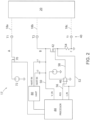
- the I/O module 16 can include multiple terminals 40, such as terminals T1, T2, T3, each being configured to receive electrical conductors, such as conductors 18a, 18b, 18c, respectively, in channels interfacing with the equipment 20.
- the conductors 18a, 18b, 18c are illustrated in phantom lines indicating the various possibilities for connection to the equipment 20 according to various devices and/or modes.
- the conductors 18 can be wires variously configured for communicating with equipment 20, which could comprise sensors or actuators, any of which may be digital, analog and/or HART devices, as may be desired at various points in the industrial process 14.
- Such conductors 18 can be releasably connected to the I/O module 16 at the terminals 40.
- the terminals 40 can be screw terminals in which a screw driver, such as a slotted or flat-blade screwdriver or other type, can be used to releasably connect the conductors 18 to the I/O module 16.
- a variable resistance device 42 which can be a transistor, and which preferably can be a Field Effect Transistor (FET), can be connected to a terminal 40, such as the terminal T2, providing a resistance in the channel (identified as "B") in line with the conductor 18b.
- a control circuit which in one aspect can include a processor 44 connected to an amplifier 46, can be connected to the variable resistance device 42. The control circuit can be configured to control the variable resistance device 42 to adjust the resistance in the channel in line with the conductor 18b for a given mode selected from multiple modes of operation.
- a mode of operation can be determined, such as by the processor 44, from user input which could indicate requirements for the equipment 20, which could be provided through a screen of a remote device 34, the central computer system 30 or the industrial controller 12 or to the I/O module 16 directly.
- user input may indicate, for example, power, voltage and/or current requirements for the equipment 20, or simply whether the equipment 20 is a predetermined device type, such as a digital sensor, including an IEC type 1, 2, 3 or NAMUR sensor, a digital actuator, an analog sensor, an analog sensor operating as a HART device, or an analog actuator, or a user defined device type.
- Determined modes of operation could then be set, such as digital output, digital input for IEC type 1, 2, 3 or NAMUR, analog output, analog input without HART communications, analog input with HART communications (which can be implemented in a 4-20 mA current loop), user defined, and so forth. Accordingly, each mode of operation could configure a different resistance in the channel specific for the device type.
- a mode for digital output could cause the control circuit to control the variable resistance device to minimize the resistance in the channel, preferably to 0 ⁇ ; a mode for digital input for IEC type 1, 2, 3 could cause the control circuit to control the variable resistance device to adjust the resistance in the channel to a higher resistance (than for analog input), such as to 3.3k ⁇ ; a mode for digital input for NAMUR could also cause the control circuit to control the variable resistance device to adjust the resistance in the channel to a higher resistance (than for analog input), but with less resistance than for IEC type 1, 2, 3, such as to 1k ⁇ ; a mode for analog output could cause the control circuit to control the variable resistance device to vary the resistance in the channel to maintain a constant current in the channel; a mode for analog input with HART communications could cause the control circuit to control the variable resistance device to adjust the resistance in the channel to a lower resistance (than for digital input), such as to 250 ⁇ ; and a mode for analog input without HART communications could also cause the control circuit to control the variable resistance device to adjust the resistance in
- the control circuit can control the variable resistance device 42 to provide the resistance in the channel (B) as desired by receiving feedback from the channel for the amplifier 46 which, in turn, can provide the adjustment for the variable resistance device 42, such as by driving a gate of the FET to selectively bias the transistor to achieve a resistance in the channel suitable for the selected mode.
- a voltage feedback line 50 (“V_ IN"), from a node between the variable resistance device 42 and the screw terminal T2
- a current feedback line 52 (IIN”), from a node between the variable resistance device 42 and a current sensing resistor 54
- the current sensing resistor 54 could be a nominal resistor, such as 20 ⁇ , connected to ground.
- the current feedback line 52 can also be provided to another input of the amplifier 46, such as a non-inverting input ("+”), providing a reference.
- the amplifier 46 could be, for example, an ADA 4891 Low Cost CMOS, High Speed, Rail -to-Rail Amplifier, as available from Analog Devices, Inc. of Norwood, MA.
- an alternative circuit portion 17' illustrates an alternative control circuit for the I/O module 16.
- a resistor divider 60 can be connected to the amplifier 46.
- the voltage feedback line 50 from the node between the variable resistance device 42 and the screw terminal T2, can be connected to a first side of a first resistor 62 in the resistor divider 60.
- a second side of the first resistor 62, at an adjusting node 66, can be connected in series to a first side of a second resistor 64 in the resistor divider 60.
- the second side of the second resistor 64 can be connected to ground.
- the second resistor 64 could be, for example, a digital potentiometer which could be configured by a processor to implement various resistances.
- the adjusting node 66 can then adjust the resistance in the channel by adjusting input of the amplifier 46, such as the non-inverting input ("+ "), so that the amplifier 46, in turn, provides the adjustment to the variable resistance device 42 through the biasing line 58.
- the current feedback line 52 can again be provided to another input of the amplifier 46, such as the inverting input ("--"), providing a reference.
- the processor which could determine a given mode from user input, can configure the second resistor 64 (digital potentiometer) according to the given mode to implement the desired resistance in the channel.
- various modes of operation which can be implemented by the I/O module 16, using the circuit portion 17 or the alternative circuit portion 17', include, for example: digital output, digital input for IEC type 1, 2, 3 or NAMUR, analog output, analog input without HART communications, analog input with HART communications (which can be implemented in a 4-20 mA current loop). Moreover, a further customized, user defined mode of operation can also be provided.
- the processor 44 can control a switch 70 to selectively provide power from a power source 72 to terminal T1 in an output channel (identified as "A") as required by the digital device.
- a conductor 18a, releasably connected to the terminal T1 can provide such selectively delivered power to the equipment 20.
- a conductor 18b, releasably connected to the terminal T2 in turn, can provide a return path in a return channel (channel B), in line with the variable resistance device 42, from the equipment 20.
- the control circuit using processor 44 and/or resistor divider 60
- a conductor 18b releasably connected to the terminal T2
- a conductor 18c releasably connected to the terminal T3
- the control circuit can control the variable resistance device 42 to adjust the resistance in the channel to a higher resistance (than for analog input), such as to 3.3k ⁇ , as may be required by the system.
- a conductor 18b, releasably connected to the terminal T2 can again provide an input from the equipment 20.
- a conductor 18c, releasably connected to the terminal T3 can again provide a return path in a return channel (channel C) connected to ground.
- the control circuit using processor 44 and/or resistor divider 60
- the variable resistance device 42 can control the variable resistance device 42 to adjust the resistance in the channel to a higher resistance (than for analog input), but with less resistance than for IEC type 1, 2, 3, such as to 1k ⁇ .
- the processor 44 can control a switch 70 to selectively provide power from a power source 72 to terminal T1 in an output channel (identified as "A") as required by the analog device.
- a conductor 18a, releasably connected to the terminal T1 can provide such selectively delivered power to the equipment 20.
- a conductor 18b, releasably connected to the terminal T2 in turn, can provide a return path in a return channel (channel B), in line with the variable resistance device 42, from the equipment 20.
- the control circuit using processor 44 and/or resistor divider 60
- a conductor 18b releasably connected to the terminal T2
- a conductor 18c, releasably connected to the terminal T3 can provide a return path in a return channel (channel C) connected to ground.
- the control circuit using processor 44 and/or resistor divider 60
- a conductor 18b releasably connected to the terminal T2
- a conductor 18c releasably connected to the terminal T3
- the control circuit can control the variable resistance device 42 to adjust the resistance in the channel to a lower resistance (than for digital input), but even less resistance than for an analog input with HART communications, such as to 100 ⁇ .
Landscapes
- Engineering & Computer Science (AREA)
- Physics & Mathematics (AREA)
- General Physics & Mathematics (AREA)
- General Engineering & Computer Science (AREA)
- Automation & Control Theory (AREA)
- Theoretical Computer Science (AREA)
- Manufacturing & Machinery (AREA)
- Quality & Reliability (AREA)
- Programmable Controllers (AREA)
- Networks Using Active Elements (AREA)
Claims (14)
- Module d'interfaçage avec un équipement de commande industriel, comprenant :une borne (40) configurée pour recevoir un conducteur électrique dans un canal en interface avec un équipement de commande industriel (20) ;un dispositif à résistance variable (42) connecté à la borne (40) et adapté pour fournir une résistance dans le canal ; etun circuit de commande (44, 46) connecté au dispositif à résistance variable (42),dans lequel le circuit de commande (44, 46) est configuré pour commander le dispositif à résistance variable (42) afin d'ajuster la résistance dans le canal pour un mode donné sélectionné parmi une pluralité de modes, dans lequel chaque mode de la pluralité de modes configure une résistance différente dans le canal, etdans lequel la pluralité de modes comprend des modes de sortie numérique, d'entrée numérique, de sortie analogique et d'entrée analogique.
- Module selon la revendication 1, dans lequel la borne (40) est une borne à vis, et dans lequel le dispositif à résistance variable (42) est un transistor.
- Module selon la revendication 2, dans lequel le circuit de commande (44, 46) comprend un processeur (44) connecté à un amplificateur (46), dans lequel le transistor (42) est un transistor à effet de champ, FET, et dans lequel l'amplificateur (46) est adapté pour attaquer une grille du FET (42).
- Module selon la revendication 3 comprenant au moins une parmi :
une résistance (54) pour une détection de courant connectée au FET (42), la résistance (54) étant en outre connectée à une première entrée de l'amplificateur (46) et le processeur (44) étant connecté à une seconde entrée de l'amplificateur (46) ; et dans lequel le mode donné est déterminé par le processeur (44) à partir d'une entrée utilisateur. - Module selon la revendication 2, dans lequel le circuit de commande (44, 46) comprend un diviseur de résistance (60) ayant une première résistance (62) connectée en série avec une seconde résistance (64), dans lequel une borne commune entre les première et seconde résistances (62, 64) est connectée à une entrée non-inverseuse d'un amplificateur (46), dans lequel le transistor (42) est un transistor à effet de champ, FET, et dans lequel l'amplificateur (46) est adapté pour attaquer une grille du FET.
- Module selon la revendication 5, dans lequel le diviseur de résistance (60) comprend la première résistance (62) en série avec un potentiomètre numérique (64).
- Module selon la revendication 6, comprenant en outre un processeur (44) adapté pour configurer le potentiomètre numérique (64), dans lequel le mode donné est déterminé par le processeur (44) à partir d'une entrée utilisateur, et dans lequel le processeur (44) est en outre adapté pour configurer le potentiomètre numérique (64) en fonction du mode donné.
- Module selon la revendication 1, dans lequel le circuit de commande (44, 46) est adapté pour commander le dispositif à résistance variable (42) afin de fournir une résistance plus élevée dans le canal lorsque le mode est pour une entrée numérique et une résistance plus faible dans le canal lorsque le mode est pour une entrée analogique.
- Module selon la revendication 1, dans lequel la pluralité de modes comprend en outre un mode d'entrée analogique avec des communications par transducteur à distance adressable sur autoroute, HART, dans une boucle de courant de 4 à 20 mA.
- Module selon la revendication 9, dans lequel le circuit de commande (44, 46) est adapté pour commander le dispositif à résistance variable (42) afin de fournir une résistance plus élevée dans le canal lorsque le mode est pour une entrée analogique et une résistance plus faible dans le canal lorsque le mode est pour une entrée analogique avec des communications HART.
- Module selon la revendication 1 comprenant au moins un parmi :le circuit de commande (44, 46) est adapté pour commander le dispositif à résistance variable (42) afin de minimiser la résistance dans le canal lorsque le mode est pour une sortie numérique ;le circuit de commande (44, 46) est adapté pour commander le dispositif à résistance variable (42) afin de faire varier la résistance dans le canal pour maintenir un courant constant dans le canal lorsque le mode est pour une sortie analogique ;la borne (40) est une première borne dans un premier canal, et comprenant en outre une seconde borne configurée pour recevoir un conducteur électrique dans un second canal en interface avec un équipement de commande industriel (20) comprenant un actionneur, et dans lequel le second canal est adapté pour fournir une sortie depuis une source d'alimentation (72) à l'équipement de commande industriel (20) dans les modes de sortie numérique et de sortie analogique tandis que le premier canal fournit un chemin de retour ; etla borne (40) est une première borne dans un premier canal, et comprenant en outre une seconde borne configurée pour recevoir un conducteur électrique dans un second canal en interface avec un équipement de commande industriel (20) comprenant un capteur, et dans lequel le premier canal est adapté pour fournir une entrée depuis l'équipement de commande industriel (20) dans les modes d'entrée numérique etd'entrée analogique tandis que le second canal fournit un chemin de retour vers la terre.
- Système de commande industriel comprenant :un dispositif de commande industriel (12) adapté pour exécuter un programme de commande pour commander un processus industriel ; etle module (17) d'interfaçage selon la revendication 1.
- Système de commande industriel selon la revendication 12, dans lequel la borne (40) est une borne à vis, et dans lequel le dispositif à résistance variable (42) est un FET avec le circuit de commande (44, 46) connecté à une grille du FET.
- Système de commande industriel selon la revendication 12 ou 13, dans lequel la pluralité de modes comprend un mode d'entrée analogique avec des communications par transducteur à distance adressable sur autoroute, HART, dans une boucle de courant de 4 à 20 mA, et dans lequel le circuit de commande (44, 46) est adapté pour commander le dispositif à résistance variable (42) afin de minimiser la résistance dans le canal lorsque le mode donné est pour une sortie numérique, et dans lequel le circuit de commande (44, 46) est adapté pour commander le dispositif à résistance variable (42) pour faire varier la résistance dans le canal pour maintenir un courant constant dans le canal lorsque le mode donné est pour une sortie analogique.
Applications Claiming Priority (2)
| Application Number | Priority Date | Filing Date | Title |
|---|---|---|---|
| US15/959,985 US10684611B2 (en) | 2018-04-23 | 2018-04-23 | Industrial control module providing universal I/O |
| EP19165192.6A EP3561618B1 (fr) | 2018-04-23 | 2019-03-26 | Module de commande industriel permettant une e/s universelle |
Related Parent Applications (1)
| Application Number | Title | Priority Date | Filing Date |
|---|---|---|---|
| EP19165192.6A Division EP3561618B1 (fr) | 2018-04-23 | 2019-03-26 | Module de commande industriel permettant une e/s universelle |
Publications (4)
| Publication Number | Publication Date |
|---|---|
| EP3916498A2 EP3916498A2 (fr) | 2021-12-01 |
| EP3916498A3 EP3916498A3 (fr) | 2022-02-16 |
| EP3916498C0 EP3916498C0 (fr) | 2023-12-06 |
| EP3916498B1 true EP3916498B1 (fr) | 2023-12-06 |
Family
ID=66217671
Family Applications (2)
| Application Number | Title | Priority Date | Filing Date |
|---|---|---|---|
| EP21186696.7A Active EP3916498B1 (fr) | 2018-04-23 | 2019-03-26 | Module de commande industriel permettant une e/s universelle |
| EP19165192.6A Active EP3561618B1 (fr) | 2018-04-23 | 2019-03-26 | Module de commande industriel permettant une e/s universelle |
Family Applications After (1)
| Application Number | Title | Priority Date | Filing Date |
|---|---|---|---|
| EP19165192.6A Active EP3561618B1 (fr) | 2018-04-23 | 2019-03-26 | Module de commande industriel permettant une e/s universelle |
Country Status (3)
| Country | Link |
|---|---|
| US (2) | US10684611B2 (fr) |
| EP (2) | EP3916498B1 (fr) |
| CN (1) | CN110389566B (fr) |
Families Citing this family (7)
| Publication number | Priority date | Publication date | Assignee | Title |
|---|---|---|---|---|
| US10684611B2 (en) * | 2018-04-23 | 2020-06-16 | Rockwell Automation Technologies, Inc. | Industrial control module providing universal I/O |
| US11269790B2 (en) * | 2019-04-18 | 2022-03-08 | Emerson Process Management Power & Water Solutions, Inc. | Implementing and configuring a universal I/O card for a process control I/O network |
| US20220291055A1 (en) * | 2021-03-12 | 2022-09-15 | Allegro Microsystems, Llc | Sensor interface with temperature signal processing |
| US11852691B2 (en) | 2021-08-24 | 2023-12-26 | Rockwell Automation Technologies, Inc. | Input/output (IO) module power supply with online load test capability |
| US11860599B2 (en) | 2021-09-27 | 2024-01-02 | Rockwell Automation Technologies, Inc. | High availability redundant power distribution system diagnostic operations |
| US11899445B2 (en) | 2021-09-27 | 2024-02-13 | Rockwell Automation Technologies, Inc. | High availability redundant power distribution systems and methods |
| CN114815720B (zh) * | 2022-06-29 | 2022-09-09 | 天津飞旋科技股份有限公司 | 可编程控制器及其模拟量复用接口控制方法、存储介质 |
Family Cites Families (15)
| Publication number | Priority date | Publication date | Assignee | Title |
|---|---|---|---|---|
| US4593380A (en) | 1984-06-04 | 1986-06-03 | General Electric Co. | Dual function input/output for a programmable controller |
| US4875023A (en) * | 1988-05-10 | 1989-10-17 | Grumman Aerospace Corporation | Variable attenuator having voltage variable FET resistor with chosen resistance-voltage relationship |
| US5233289A (en) * | 1991-04-23 | 1993-08-03 | Harris Corporation | Voltage divider and use as bias network for stacked transistors |
| CA2084760A1 (fr) | 1991-12-13 | 1993-06-14 | Glenn Bradley Bilane | Circuit et module d'entree-sortie multimode et systeme de controle de processus utilisant ceux-ci |
| US6904527B1 (en) * | 2000-03-14 | 2005-06-07 | Xilinx, Inc. | Intellectual property protection in a programmable logic device |
| US7028105B2 (en) | 2000-07-25 | 2006-04-11 | Electronic Solutions, Inc. | Apparatus, method and signal set for monoline serial interface |
| US20030169875A1 (en) * | 2002-03-07 | 2003-09-11 | Lsi Logic Corporation | On-chip compensation scheme for bridged tap lines in ADSL hybrid |
| US7970003B2 (en) * | 2003-05-30 | 2011-06-28 | General Dynamics Advanced Information Systems Inc. | Low power telemetry system and method |
| US20080079476A1 (en) * | 2006-09-29 | 2008-04-03 | Michael Wendell Vice | Gate load impedance networks for field effect transistor attenuators and mixers |
| US20080291723A1 (en) * | 2007-05-23 | 2008-11-27 | Wang Daniel C | Source biasing of nor-type flash array with dynamically variable source resistance |
| US8786128B2 (en) | 2010-05-11 | 2014-07-22 | Rosemount Inc. | Two-wire industrial process field device with power scavenging |
| CN102032928A (zh) * | 2010-12-15 | 2011-04-27 | 上海工业自动化仪表研究院 | 一种通用型hart变送模块及工作方法 |
| US8669787B2 (en) * | 2012-05-17 | 2014-03-11 | Rockwell Automation Technologies, Inc. | Zero-crossing detector for industrial control with low heat dissipation |
| US9979183B2 (en) * | 2015-07-27 | 2018-05-22 | Nxp B.V. | Over voltage protection circuit |
| US10684611B2 (en) * | 2018-04-23 | 2020-06-16 | Rockwell Automation Technologies, Inc. | Industrial control module providing universal I/O |
-
2018
- 2018-04-23 US US15/959,985 patent/US10684611B2/en active Active
-
2019
- 2019-03-26 EP EP21186696.7A patent/EP3916498B1/fr active Active
- 2019-03-26 EP EP19165192.6A patent/EP3561618B1/fr active Active
- 2019-04-11 CN CN201910288942.7A patent/CN110389566B/zh active Active
-
2020
- 2020-05-19 US US16/877,983 patent/US11209802B2/en active Active
Also Published As
| Publication number | Publication date |
|---|---|
| EP3561618B1 (fr) | 2021-08-11 |
| US20200278664A1 (en) | 2020-09-03 |
| US20190324429A1 (en) | 2019-10-24 |
| EP3561618A2 (fr) | 2019-10-30 |
| CN110389566B (zh) | 2022-08-02 |
| US11209802B2 (en) | 2021-12-28 |
| EP3561618A3 (fr) | 2019-11-27 |
| EP3916498A3 (fr) | 2022-02-16 |
| EP3916498C0 (fr) | 2023-12-06 |
| EP3916498A2 (fr) | 2021-12-01 |
| US10684611B2 (en) | 2020-06-16 |
| CN110389566A (zh) | 2019-10-29 |
Similar Documents
| Publication | Publication Date | Title |
|---|---|---|
| EP3916498B1 (fr) | Module de commande industriel permettant une e/s universelle | |
| US6574515B1 (en) | Two-wire field-mounted process device | |
| US7016741B2 (en) | Process control loop signal converter | |
| US7844365B2 (en) | Field-mounted process device | |
| EP1960892B1 (fr) | Système pour la commande programmée d'une entrée et d'une sortie de signal vers ou depuis des conducteurs de câbles | |
| CA2899042C (fr) | Circuit d'interface programmable pour connecter des dispositifs de terrain a un systeme de commande de processus | |
| US8806085B2 (en) | Application specific integrated circuit (ASIC) disposed in input/output module connectable to programmable logic controller (PLC) based systems having plurality of connection paths | |
| US20120047288A1 (en) | Input/Output Devices Having Re-Configurable Functionality | |
| EP0546855A1 (fr) | Circuit et module d'entrée/sortie à modes multiples, et système de commande de processus les utilisant | |
| CN105408945B (zh) | 具有用于传送测量信号的可切换的测量和操作电子设备的测量装置 | |
| EP2726997B1 (fr) | Terminaison de bus en série de diffusion | |
| CN114787726A (zh) | 用于监测和/或控制动态环境的输入/输出设备和方法 | |
| US20220260960A1 (en) | Automation field device | |
| US6744393B2 (en) | Low cost multi-range input circuit for industrial analog input modules | |
| KR200325286Y1 (ko) | 아날로그 트랜스미터 모듈 | |
| EP2952987A1 (fr) | Dispositif de commande | |
| WO2013117820A1 (fr) | Dispositif de communication fieldbus |
Legal Events
| Date | Code | Title | Description |
|---|---|---|---|
| PUAI | Public reference made under article 153(3) epc to a published international application that has entered the european phase |
Free format text: ORIGINAL CODE: 0009012 |
|
| STAA | Information on the status of an ep patent application or granted ep patent |
Free format text: STATUS: THE APPLICATION HAS BEEN PUBLISHED |
|
| AC | Divisional application: reference to earlier application |
Ref document number: 3561618 Country of ref document: EP Kind code of ref document: P |
|
| AK | Designated contracting states |
Kind code of ref document: A2 Designated state(s): AL AT BE BG CH CY CZ DE DK EE ES FI FR GB GR HR HU IE IS IT LI LT LU LV MC MK MT NL NO PL PT RO RS SE SI SK SM TR |
|
| PUAL | Search report despatched |
Free format text: ORIGINAL CODE: 0009013 |
|
| AK | Designated contracting states |
Kind code of ref document: A3 Designated state(s): AL AT BE BG CH CY CZ DE DK EE ES FI FR GB GR HR HU IE IS IT LI LT LU LV MC MK MT NL NO PL PT RO RS SE SI SK SM TR |
|
| RIC1 | Information provided on ipc code assigned before grant |
Ipc: G06F 13/38 20060101ALN20220110BHEP Ipc: G05B 19/05 20060101ALI20220110BHEP Ipc: G05B 19/042 20060101AFI20220110BHEP |
|
| STAA | Information on the status of an ep patent application or granted ep patent |
Free format text: STATUS: REQUEST FOR EXAMINATION WAS MADE |
|
| 17P | Request for examination filed |
Effective date: 20220810 |
|
| RBV | Designated contracting states (corrected) |
Designated state(s): AL AT BE BG CH CY CZ DE DK EE ES FI FR GB GR HR HU IE IS IT LI LT LU LV MC MK MT NL NO PL PT RO RS SE SI SK SM TR |
|
| RIC1 | Information provided on ipc code assigned before grant |
Ipc: G06F 13/38 20060101ALN20230501BHEP Ipc: G05B 19/05 20060101ALI20230501BHEP Ipc: G05B 19/042 20060101AFI20230501BHEP |
|
| GRAP | Despatch of communication of intention to grant a patent |
Free format text: ORIGINAL CODE: EPIDOSNIGR1 |
|
| STAA | Information on the status of an ep patent application or granted ep patent |
Free format text: STATUS: GRANT OF PATENT IS INTENDED |
|
| RIC1 | Information provided on ipc code assigned before grant |
Ipc: G06F 13/38 20060101ALN20230529BHEP Ipc: G05B 19/05 20060101ALI20230529BHEP Ipc: G05B 19/042 20060101AFI20230529BHEP |
|
| INTG | Intention to grant announced |
Effective date: 20230621 |
|
| GRAS | Grant fee paid |
Free format text: ORIGINAL CODE: EPIDOSNIGR3 |
|
| GRAA | (expected) grant |
Free format text: ORIGINAL CODE: 0009210 |
|
| STAA | Information on the status of an ep patent application or granted ep patent |
Free format text: STATUS: THE PATENT HAS BEEN GRANTED |
|
| AC | Divisional application: reference to earlier application |
Ref document number: 3561618 Country of ref document: EP Kind code of ref document: P |
|
| AK | Designated contracting states |
Kind code of ref document: B1 Designated state(s): AL AT BE BG CH CY CZ DE DK EE ES FI FR GB GR HR HU IE IS IT LI LT LU LV MC MK MT NL NO PL PT RO RS SE SI SK SM TR |
|
| REG | Reference to a national code |
Ref country code: GB Ref legal event code: FG4D |
|
| REG | Reference to a national code |
Ref country code: CH Ref legal event code: EP |
|
| REG | Reference to a national code |
Ref country code: DE Ref legal event code: R096 Ref document number: 602019043072 Country of ref document: DE |
|
| REG | Reference to a national code |
Ref country code: IE Ref legal event code: FG4D |
|
| U01 | Request for unitary effect filed |
Effective date: 20231207 |
|
| U07 | Unitary effect registered |
Designated state(s): AT BE BG DE DK EE FI FR IT LT LU LV MT NL PT SE SI Effective date: 20231213 |
|
| U20 | Renewal fee paid [unitary effect] |
Year of fee payment: 6 Effective date: 20240220 |
|
| PG25 | Lapsed in a contracting state [announced via postgrant information from national office to epo] |
Ref country code: GR Free format text: LAPSE BECAUSE OF FAILURE TO SUBMIT A TRANSLATION OF THE DESCRIPTION OR TO PAY THE FEE WITHIN THE PRESCRIBED TIME-LIMIT Effective date: 20240307 |
|
| PG25 | Lapsed in a contracting state [announced via postgrant information from national office to epo] |
Ref country code: ES Free format text: LAPSE BECAUSE OF FAILURE TO SUBMIT A TRANSLATION OF THE DESCRIPTION OR TO PAY THE FEE WITHIN THE PRESCRIBED TIME-LIMIT Effective date: 20231206 |
|
| PG25 | Lapsed in a contracting state [announced via postgrant information from national office to epo] |
Ref country code: GR Free format text: LAPSE BECAUSE OF FAILURE TO SUBMIT A TRANSLATION OF THE DESCRIPTION OR TO PAY THE FEE WITHIN THE PRESCRIBED TIME-LIMIT Effective date: 20240307 Ref country code: ES Free format text: LAPSE BECAUSE OF FAILURE TO SUBMIT A TRANSLATION OF THE DESCRIPTION OR TO PAY THE FEE WITHIN THE PRESCRIBED TIME-LIMIT Effective date: 20231206 |
|
| PGFP | Annual fee paid to national office [announced via postgrant information from national office to epo] |
Ref country code: GB Payment date: 20240221 Year of fee payment: 6 |