EP3916291B1 - Headlamp device for a vehicle - Google Patents
Headlamp device for a vehicle Download PDFInfo
- Publication number
- EP3916291B1 EP3916291B1 EP21176186.1A EP21176186A EP3916291B1 EP 3916291 B1 EP3916291 B1 EP 3916291B1 EP 21176186 A EP21176186 A EP 21176186A EP 3916291 B1 EP3916291 B1 EP 3916291B1
- Authority
- EP
- European Patent Office
- Prior art keywords
- light
- focal point
- lens assembly
- light source
- incident surface
- Prior art date
- Legal status (The legal status is an assumption and is not a legal conclusion. Google has not performed a legal analysis and makes no representation as to the accuracy of the status listed.)
- Active
Links
Images


Classifications
-
- F—MECHANICAL ENGINEERING; LIGHTING; HEATING; WEAPONS; BLASTING
- F21—LIGHTING
- F21S—NON-PORTABLE LIGHTING DEVICES; SYSTEMS THEREOF; VEHICLE LIGHTING DEVICES SPECIALLY ADAPTED FOR VEHICLE EXTERIORS
- F21S41/00—Illuminating devices specially adapted for vehicle exteriors, e.g. headlamps
- F21S41/10—Illuminating devices specially adapted for vehicle exteriors, e.g. headlamps characterised by the light source
- F21S41/14—Illuminating devices specially adapted for vehicle exteriors, e.g. headlamps characterised by the light source characterised by the type of light source
- F21S41/141—Light emitting diodes [LED]
- F21S41/147—Light emitting diodes [LED] the main emission direction of the LED being angled to the optical axis of the illuminating device
- F21S41/148—Light emitting diodes [LED] the main emission direction of the LED being angled to the optical axis of the illuminating device the main emission direction of the LED being perpendicular to the optical axis
-
- F—MECHANICAL ENGINEERING; LIGHTING; HEATING; WEAPONS; BLASTING
- F21—LIGHTING
- F21S—NON-PORTABLE LIGHTING DEVICES; SYSTEMS THEREOF; VEHICLE LIGHTING DEVICES SPECIALLY ADAPTED FOR VEHICLE EXTERIORS
- F21S41/00—Illuminating devices specially adapted for vehicle exteriors, e.g. headlamps
- F21S41/10—Illuminating devices specially adapted for vehicle exteriors, e.g. headlamps characterised by the light source
- F21S41/14—Illuminating devices specially adapted for vehicle exteriors, e.g. headlamps characterised by the light source characterised by the type of light source
- F21S41/141—Light emitting diodes [LED]
- F21S41/143—Light emitting diodes [LED] the main emission direction of the LED being parallel to the optical axis of the illuminating device
-
- F—MECHANICAL ENGINEERING; LIGHTING; HEATING; WEAPONS; BLASTING
- F21—LIGHTING
- F21S—NON-PORTABLE LIGHTING DEVICES; SYSTEMS THEREOF; VEHICLE LIGHTING DEVICES SPECIALLY ADAPTED FOR VEHICLE EXTERIORS
- F21S41/00—Illuminating devices specially adapted for vehicle exteriors, e.g. headlamps
- F21S41/10—Illuminating devices specially adapted for vehicle exteriors, e.g. headlamps characterised by the light source
- F21S41/14—Illuminating devices specially adapted for vehicle exteriors, e.g. headlamps characterised by the light source characterised by the type of light source
- F21S41/141—Light emitting diodes [LED]
- F21S41/151—Light emitting diodes [LED] arranged in one or more lines
-
- F—MECHANICAL ENGINEERING; LIGHTING; HEATING; WEAPONS; BLASTING
- F21—LIGHTING
- F21S—NON-PORTABLE LIGHTING DEVICES; SYSTEMS THEREOF; VEHICLE LIGHTING DEVICES SPECIALLY ADAPTED FOR VEHICLE EXTERIORS
- F21S41/00—Illuminating devices specially adapted for vehicle exteriors, e.g. headlamps
- F21S41/20—Illuminating devices specially adapted for vehicle exteriors, e.g. headlamps characterised by refractors, transparent cover plates, light guides or filters
- F21S41/25—Projection lenses
- F21S41/265—Composite lenses; Lenses with a patch-like shape
-
- F—MECHANICAL ENGINEERING; LIGHTING; HEATING; WEAPONS; BLASTING
- F21—LIGHTING
- F21S—NON-PORTABLE LIGHTING DEVICES; SYSTEMS THEREOF; VEHICLE LIGHTING DEVICES SPECIALLY ADAPTED FOR VEHICLE EXTERIORS
- F21S41/00—Illuminating devices specially adapted for vehicle exteriors, e.g. headlamps
- F21S41/30—Illuminating devices specially adapted for vehicle exteriors, e.g. headlamps characterised by reflectors
- F21S41/32—Optical layout thereof
- F21S41/321—Optical layout thereof the reflector being a surface of revolution or a planar surface, e.g. truncated
-
- F—MECHANICAL ENGINEERING; LIGHTING; HEATING; WEAPONS; BLASTING
- F21—LIGHTING
- F21S—NON-PORTABLE LIGHTING DEVICES; SYSTEMS THEREOF; VEHICLE LIGHTING DEVICES SPECIALLY ADAPTED FOR VEHICLE EXTERIORS
- F21S41/00—Illuminating devices specially adapted for vehicle exteriors, e.g. headlamps
- F21S41/40—Illuminating devices specially adapted for vehicle exteriors, e.g. headlamps characterised by screens, non-reflecting members, light-shielding members or fixed shades
- F21S41/43—Illuminating devices specially adapted for vehicle exteriors, e.g. headlamps characterised by screens, non-reflecting members, light-shielding members or fixed shades characterised by the shape thereof
-
- F—MECHANICAL ENGINEERING; LIGHTING; HEATING; WEAPONS; BLASTING
- F21—LIGHTING
- F21S—NON-PORTABLE LIGHTING DEVICES; SYSTEMS THEREOF; VEHICLE LIGHTING DEVICES SPECIALLY ADAPTED FOR VEHICLE EXTERIORS
- F21S41/00—Illuminating devices specially adapted for vehicle exteriors, e.g. headlamps
- F21S41/60—Illuminating devices specially adapted for vehicle exteriors, e.g. headlamps characterised by a variable light distribution
- F21S41/65—Illuminating devices specially adapted for vehicle exteriors, e.g. headlamps characterised by a variable light distribution by acting on light sources
- F21S41/663—Illuminating devices specially adapted for vehicle exteriors, e.g. headlamps characterised by a variable light distribution by acting on light sources by switching light sources
-
- F—MECHANICAL ENGINEERING; LIGHTING; HEATING; WEAPONS; BLASTING
- F21—LIGHTING
- F21S—NON-PORTABLE LIGHTING DEVICES; SYSTEMS THEREOF; VEHICLE LIGHTING DEVICES SPECIALLY ADAPTED FOR VEHICLE EXTERIORS
- F21S43/00—Signalling devices specially adapted for vehicle exteriors, e.g. brake lamps, direction indicator lights or reversing lights
- F21S43/10—Signalling devices specially adapted for vehicle exteriors, e.g. brake lamps, direction indicator lights or reversing lights characterised by the light source
- F21S43/13—Signalling devices specially adapted for vehicle exteriors, e.g. brake lamps, direction indicator lights or reversing lights characterised by the light source characterised by the type of light source
- F21S43/14—Light emitting diodes [LED]
-
- F—MECHANICAL ENGINEERING; LIGHTING; HEATING; WEAPONS; BLASTING
- F21—LIGHTING
- F21S—NON-PORTABLE LIGHTING DEVICES; SYSTEMS THEREOF; VEHICLE LIGHTING DEVICES SPECIALLY ADAPTED FOR VEHICLE EXTERIORS
- F21S43/00—Signalling devices specially adapted for vehicle exteriors, e.g. brake lamps, direction indicator lights or reversing lights
- F21S43/10—Signalling devices specially adapted for vehicle exteriors, e.g. brake lamps, direction indicator lights or reversing lights characterised by the light source
- F21S43/13—Signalling devices specially adapted for vehicle exteriors, e.g. brake lamps, direction indicator lights or reversing lights characterised by the light source characterised by the type of light source
- F21S43/15—Strips of light sources
-
- F—MECHANICAL ENGINEERING; LIGHTING; HEATING; WEAPONS; BLASTING
- F21—LIGHTING
- F21S—NON-PORTABLE LIGHTING DEVICES; SYSTEMS THEREOF; VEHICLE LIGHTING DEVICES SPECIALLY ADAPTED FOR VEHICLE EXTERIORS
- F21S43/00—Signalling devices specially adapted for vehicle exteriors, e.g. brake lamps, direction indicator lights or reversing lights
- F21S43/20—Signalling devices specially adapted for vehicle exteriors, e.g. brake lamps, direction indicator lights or reversing lights characterised by refractors, transparent cover plates, light guides or filters
- F21S43/26—Refractors, transparent cover plates, light guides or filters not provided in groups F21S43/235 - F21S43/255
-
- B—PERFORMING OPERATIONS; TRANSPORTING
- B60—VEHICLES IN GENERAL
- B60Q—ARRANGEMENT OF SIGNALLING OR LIGHTING DEVICES, THE MOUNTING OR SUPPORTING THEREOF OR CIRCUITS THEREFOR, FOR VEHICLES IN GENERAL
- B60Q2400/00—Special features or arrangements of exterior signal lamps for vehicles
- B60Q2400/30—Daytime running lights [DRL], e.g. circuits or arrangements therefor
-
- F—MECHANICAL ENGINEERING; LIGHTING; HEATING; WEAPONS; BLASTING
- F21—LIGHTING
- F21S—NON-PORTABLE LIGHTING DEVICES; SYSTEMS THEREOF; VEHICLE LIGHTING DEVICES SPECIALLY ADAPTED FOR VEHICLE EXTERIORS
- F21S41/00—Illuminating devices specially adapted for vehicle exteriors, e.g. headlamps
- F21S41/20—Illuminating devices specially adapted for vehicle exteriors, e.g. headlamps characterised by refractors, transparent cover plates, light guides or filters
- F21S41/29—Attachment thereof
- F21S41/295—Attachment thereof specially adapted to projection lenses
-
- F—MECHANICAL ENGINEERING; LIGHTING; HEATING; WEAPONS; BLASTING
- F21—LIGHTING
- F21W—INDEXING SCHEME ASSOCIATED WITH SUBCLASSES F21K, F21L, F21S and F21V, RELATING TO USES OR APPLICATIONS OF LIGHTING DEVICES OR SYSTEMS
- F21W2102/00—Exterior vehicle lighting devices for illuminating purposes
- F21W2102/10—Arrangement or contour of the emitted light
- F21W2102/13—Arrangement or contour of the emitted light for high-beam region or low-beam region
- F21W2102/135—Arrangement or contour of the emitted light for high-beam region or low-beam region the light having cut-off lines, i.e. clear borderlines between emitted regions and dark regions
-
- F—MECHANICAL ENGINEERING; LIGHTING; HEATING; WEAPONS; BLASTING
- F21—LIGHTING
- F21W—INDEXING SCHEME ASSOCIATED WITH SUBCLASSES F21K, F21L, F21S and F21V, RELATING TO USES OR APPLICATIONS OF LIGHTING DEVICES OR SYSTEMS
- F21W2103/00—Exterior vehicle lighting devices for signalling purposes
- F21W2103/55—Daytime running lights [DRL]
Definitions
- the invention relates to a headlamp device capable of emitting low beam and high beam light rays as known from US 2017/158113 A1 .
- the blocking board 92 is operable by the solenoid valve 91 to move relative to the light emitting member 80 in an up-down direction between an upper position and a lower position.
- the blocking board 92 is at the upper position, the light beams generated by the light emitting member 80 are reflected by the reflecting member 81 and propagate in such a manner that some of the light beams are blocked by the blocking board 92 while the remaining light beams pass through the lens 82 to serve as low beam light rays (see Figure 12 ) which form a light distribution pattern that has a clear cut-off line.
- the blocking board 92 When the blocking board 92 is at the lower position, the light beams generated by the light emitting member 80 are reflected by the reflecting member 81 and pass through the lens 82 without being blocked by the blocking board 92, so as to serve as high beam light rays (see Figure 11 ).
- the conventional headlamp device is switchable between a low beam mode where the low beam light rays are generated and a high beam mode where the high beam light rays are generated.
- the solenoid valve 91 may be slow to react to user input and is prone to malfunction. Once the solenoid valve 91 has malfunctioned, the conventional headlamp device can no longer switch between the low beam mode and the high beam mode.
- an object of the invention is to provide a headlamp device that can alleviate at least one of the drawbacks of the prior art. According to the invention, a headlamp device with the features of claim 1 is provided.
- the compound lens unit 4 includes an upper lens 41 and a lower lens assembly 42.
- the upper lens 41 has an optical axis (A), an upper light-incident surface 411, an upper light-emergent surface 412 and an upper focal point 413.
- the upper light-incident surface 411 and the upper light-emergent surface 412 are respectively located at two opposite sides of the upper lens 41 in a direction (Y) of the optical axis (A) .
- the upper light-emergent surface 412 is in front of the upper light-incident surface 411 with "front" being the forward-facing side of the headlamp device.
- the upper focal point 413 is located at one side of the upper light-incident surface 411 opposite to the upper light-emergent surface 412.
- the lower lens assembly 42 is located below the optical axis (A) of the upper lens 41, includes three lower lenses 421, and has a lower light-incident surface 422, a lower light-emergent surface 423 and a first lower focal point 424.
- the lower lenses 421 and the upper lens 41 are formed as one-piece.
- the lower light-incident surface 422 is cooperatively formed by the lower lenses 421, faces in a direction that is the same as that of the upper light-incident surface 411 of the upper lens 41, and is offset from the upper light-incident surface 411 of the upper lens 41 in the direction (Y) of the optical axis (A) (i.e., the lower light-incident surface 422 is not flush with the upper light-incident surface 411) .
- the lower light-incident surface 422 is rearwardly offset from the upper light-incident surface 411.
- the lower light-emergent surface 423 of the lower lens assembly 42 is cooperatively formed by the lower lenses 421, is opposite to the lower light-incident surface 422 in the direction (Y) of the optical axis (A) of the upper lens (41), and has a first section 427 and two second sections 428.
- the second sections 428 are respectively located at two opposite sides of the first section 427 in a transverse direction (X) transverse to the direction (Y) of the optical axis (A), and are offset from the first section 427 in the direction (Y) of the optical axis (A) (i.e., the lower light-emergent surface 423 is configured to not be a smooth surface) .
- the second sections 428 are rearwardly offset from the first section 427 in such a way that the second sections 428 are recessed relative to the first section 427.
- the first lower focal point 424 of the lower lens assembly 42 is located at one side of the lower light-incident surface 422 opposite to the lower light-emergent surface 423, and is located below the optical axis (A) .
- the first section 427 of the lower light-emergent surface 423 is formed by one of the lower lenses 421 of the lower lens assembly 42, and the second sections 428 of the lower light-emergent surface 423 are respectively formed by the other two of the lower lenses 421.
- the one of the lower lenses 421 that forms the first section 427 corresponds with the first lower focal point 424 of the lower lens assembly 42.
- the heat dissipating member 3 is where the reflector 5, the blocking board 6 and the light emitting unit 7 are disposed on.
- the heat dissipating member 3 includes a base 31 and four fins 32.
- the base 31 extends in the transverse direction (X) .
- the fins 32 are spaced apart from each other in the direction (Y) of the axis (A), and each of the fins 32 extends downwardly from the base 31.
- the first lower focal point 424 of the lower lens assembly 42 is substantially located at one of the fins 32 that is closest to the lower light-emergent surface 423 of the lower lens assembly 42.
- the reflector 5 is located at one side of the upper focal point 413 of the upper lens 41 opposite to the upper light-incident surface 411 of the upper lens 41.
- the reflector 5 has a reflecting surface 51.
- the reflecting surface 51 is arc-shaped, and has a first reflecting focal point 511 and a second reflecting focal point 512.
- the first and second reflecting focal points 511, 512 are respectively distal from and proximate to the upper light-incident surface 411 of the upper lens 41.
- the second reflecting focal point 512 coincides with the upper focal point 413 of the upper lens 41.
- the blocking board 6 is located on the heat dissipating member 3 and has a top end at which the second reflecting focal point 512 is located.
- the light emitting unit 7 includes a first light source 71 and a second light source 72.
- the first light source 71 is located on the heat dissipating member 3, substantially coincides with the first reflecting focal point 511 of the reflector 5 and has a first light emitting surface 711 facing upwardly.
- the second light source 72 substantially coincides with the first lower focal point 424 of the lower lens assembly 42 and has a second light emitting surface 721.
- the second light emitting surface 721 faces toward the lower light-incident surface 422 of the lower lens assembly 42.
- Each of the first light source 71 and the second light source 72 is operable to switch between an on-state in which light beams are generated, and an off-state in which light beams cease to be generated. It is noted that the light emitting unit 7 is a light-emitting diode made of at least one semiconductor die.
- the light beams generated by the first light source 71 are reflected by the reflecting surface 51 of the reflector 5 such that some of the light beams are blocked by the blocking board 6 (i.e., some of the reflected light beams that do not perfectly pass through the second reflecting focal point 512 of the reflecting surface 51 are blocked by the blocking board 6) while the remaining light beams travel into the upper lens 41 through the upper light-incident surface 411 and exit the upper lens 41 through the upper light-emergent surface 412 to serve as low beam light rays.
- the blocking board 6 blocking some of the light beams, light distribution pattern formed by the low beam light rays has a clear cut-off line as shown in Figure 6 .
- the light beams generated by the second light source 72 travel into the lower lens assembly 42 through the lower light-incident surface 422, and exit the lower lens assembly 42 through the lower light-emergent surface 423, so as to cooperate with the light beams exiting the upper lens 41 through the upper light-emergent surface 412 to serve as high beam light rays.
- Light distribution pattern formed by the high beam light rays is shown in Figure 7 .
- the light beams that exit the lower lens assembly 42 through the lower light-emergent surface 423 may tend to converge.
- a distance between the upper light-incident surface 411 of the upper lens 41 and the lower light-incident surface 422 of the lower lens assembly 42 in the direction (Y) of the optical axis (A) ranges from 5 to 30 millimeters. Consequently, in comparison with an aspheric lens having only one light-incident surface, the compound lens unit 4 may have a relatively small clear aperture of a minimum of 55 millimeters.
- each of the first section 427 and the second sections 428 of the lower light-emergent surface 423 is formed by the corresponding one of the lower lenses 421 of the lower lens assembly 42, curvature of each of the first section 427 and the second sections 428 is individually adjustable. In some embodiments, the curvature of each of the first section 427 and the second sections 428 is adjustable by replacing the corresponding one of the lower lenses 421 with a lens of a different curvature.
- the lower lens assembly 42 may achieve a better effect of focusing light than an aspheric lens that has a light-emergent surface without offset sections (i.e., the light-emergent surface of the aspheric lens is configured to be a smooth surface).
- a degree of overlap between the light beams exiting the upper lens 41 through the upper light-emergent surface 412 and the light beams exiting the lower lens assembly 42 through the lower light-emergent surface 423 may be adjusted to be relatively high so that the light distribution pattern formed by the high beam light rays is not dispersed.
- a reflector cup and an additional light source are necessary to generate high beam light rays. Consequently, the conventional headlamp device tends to be larger in size.
- the headlamp device of this disclosure may generate the high beam light rays without a reflector cup.
- the headlamp device therefore has a relatively small size and a relatively wide range of usage in related industries.
- a second embodiment of the headlamp device according to the invention is similar to the first embodiment. Differences between the first embodiment and the second embodiment are described below.
- the heat dissipating member 3 further includes two protrusions 33 that are located at the one of the fins 32 of the heat dissipating member 3 closest to the lower light-emergent surface 423 of the lower lens assembly 42, that are spaced apart from each other in the transverse direction (X), and that extend toward the compound lens unit 4.
- the lower lens assembly 42 further has a second lower focal point 425 and a third lower focal point 426 respectively located at two opposite sides of the first lower focal point 424 of the lower lens assembly 42 in the transverse direction (X).
- the second lower focal point 425 and the third lower focal point 426 are configured to not be on an imaginary plane that is perpendicular to the optical axis (A, with reference to Figure 3 ) and that contains the first lower focal point 424.
- the first lower focal point 424 is located between the protrusions 33 of the heat dissipating member 3, and the second lower focal point 425 and the third lower focal point 426 are respectively and substantially located at the protrusions 33 in a manner that the second lower focal point 425 and the third lower focal point 426 are located in front of the imaginary plane that contains the first lower focal point 424.
- the second lower focal point 425 and the third lower focal point 426 may be located behind the imaginary plane that contains the first lower focal point 424.
- the lower light-emergent surface 423 of the lower lens assembly 42 further has two third sections 429 each of which is located at one side of a respective one of the second sections 428 of the lower lens assembly 42 that is opposite to the first section 427 of the lower lens assembly 42 in the transverse direction (X) .
- Each of the third sections 429 is rearwardly offset from the respective one of the second section 428.
- the lower lens assembly 42 of the compound lens unit 4 includes five lower lenses 421.
- the first section 427 of the lower light-emergent surface 423 of the lower lens assembly 42 is formed by one of the lower lenses 421.
- the second sections 428 of the lower light-emergent surface 423 are respectively formed by another two of the lower lenses 421.
- the third sections 429 of the lower light-emergent surface 423 are respectively formed by the remaining two of the lower lenses 421.
- the one of the lower lenses 421 that forms the first section 427 and the another two of the lower lenses 421 that respectively form the second sections 428 cooperatively correspond with the first lower focal point 424 of the lower lens assembly 42.
- the remaining two of the lower lenses 421 respectively correspond with the second lower focal point 425 and the third lower focal point 426 of the lower lens assembly 42.
- the light emitting unit 7 further includes a third light source 73 and a fourth light source 74 that substantially coincide with the second lower focal point 425 and the third lower focal point 426, respectively.
- the third light source 73 and the fourth light source 74 are respectively located at the protrusions 33 of the heat dissipating member 3 while the second light source 72 of the light emitting unit 7 is located between the protrusions 33.
- the third light source 73 and the fourth light source 74 respectively have a third light emitting surface 731 and a fourth light emitting surface 741 that face toward the lower light-incident surface 422 of the lower lens assembly 42.
- Each of the third light source 73 and the fourth light source 74 is operable to switch between an on-state in which light beams are generated, and an off-state in which light beams cease to be generated.
- the light beams generated by the third light source 73 and the fourth light source 74 enter the lower lens assembly 42 via the lower light-incident surface 422, and propagate through the lower lens assembly 42 and then exit the same via the lower light-emergent surface 423, so as to cooperatively serve as daytime running light rays.
- the second embodiment is additionally capable of emitting daytime running light rays.
- the first embodiment and the second embodiment of the headlamp device are both capable of emitting low beam light rays and high beam light rays and are switchable between the low-beam mode and the high-beam mode without a solenoid valve. Therefore, the headlamp device according to the invention may react relatively quickly when operated, and may have a relatively long service life so reliability of the headlamp device is improved. Consequently, the drawbacks of the prior art have been alleviated and the purpose of the invention can certainly be fulfilled.
Landscapes
- Engineering & Computer Science (AREA)
- General Engineering & Computer Science (AREA)
- Physics & Mathematics (AREA)
- Microelectronics & Electronic Packaging (AREA)
- Optics & Photonics (AREA)
- Non-Portable Lighting Devices Or Systems Thereof (AREA)
Description
- The invention relates to a headlamp device capable of emitting low beam and high beam light rays as known from
US 2017/158113 A1 . - Referring to
Figures 11 and12 , a conventional headlamp device disclosed inTaiwanese Utility Model Patent No. M248960 headlamp 8 and a headlightfunction switching device 9. Theheadlamp 8 includes alight emitting member 80, a reflectingmember 81 and alens 82. Thelight emitting member 80 generates light beams. The reflectingmember 81 and thelens 82 are respectively located at two opposite sides of thelight emitting member 80. The headlightfunction switching device 9 is disposed between thelight emitting member 80 and thelens 82, and includes afixed plate 90, asolenoid valve 91 and ablocking board 92. Thesolenoid valve 91 is fixedly mounted to thefixed plate 90. Theblocking board 92 is operable by thesolenoid valve 91 to move relative to thelight emitting member 80 in an up-down direction between an upper position and a lower position. When theblocking board 92 is at the upper position, the light beams generated by thelight emitting member 80 are reflected by the reflectingmember 81 and propagate in such a manner that some of the light beams are blocked by theblocking board 92 while the remaining light beams pass through thelens 82 to serve as low beam light rays (seeFigure 12 ) which form a light distribution pattern that has a clear cut-off line. When theblocking board 92 is at the lower position, the light beams generated by thelight emitting member 80 are reflected by the reflectingmember 81 and pass through thelens 82 without being blocked by theblocking board 92, so as to serve as high beam light rays (seeFigure 11 ). - By virtue of the
solenoid valve 91 controlling theblocking board 92 to move between the upper position and the lower position, the conventional headlamp device is switchable between a low beam mode where the low beam light rays are generated and a high beam mode where the high beam light rays are generated. However, thesolenoid valve 91 may be slow to react to user input and is prone to malfunction. Once thesolenoid valve 91 has malfunctioned, the conventional headlamp device can no longer switch between the low beam mode and the high beam mode. - Therefore, an object of the invention is to provide a headlamp device that can alleviate at least one of the drawbacks of the prior art.
According to the invention, a headlamp device with the features of claim 1 is provided. - Other features and advantages of the invention will become apparent in the following detailed description of the embodiments with reference to the accompanying drawings, of which:
-
Figure 1 is a perspective view of a first embodiment of a headlamp device according to the invention -
Figure 2 is a partly exploded perspective view of the first embodiment; -
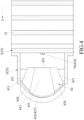
Figure 3 is a sectional view taken along line III - III inFigure 1 ; -
Figure 4 is a sectional view taken along line IV - IV inFigure 3 ; -
Figure 5 is a sectional view, similar toFigure 3 , illustrating several representative light beams that are generated by the first embodiment; -
Figure 6 is a contour plot illustrating light distribution that is formed by low beam light rays generated by the first embodiment; -
Figure 7 is a contour plot illustrating light distribution that is formed by high beam light rays generated by the first embodiment; -
Figure 8 is a partly exploded perspective view of a second embodiment of the headlamp device according to the invention; -
Figure 9 is a sectional view illustrating several representative light beams that are generated by the second embodiment; -
Figure 10 is a contour plot illustrating light distribution that is formed by daytime running light rays generated by the second embodiment; -
Figure 11 is a sectional view illustrating a conventional headlamp device when emitting high beam light rays; and -
Figure 12 is another sectional view illustrating the conventional headlamp device when emitting low beam light rays. - Before the invention is described in greater detail, it should be noted that where considered appropriate, reference numerals or terminal portions of reference numerals have been repeated among the figures to indicate corresponding or analogous elements, which may optionally have similar characteristics.
- Referring to
Figures 1 to 5 , a first embodiment of a headlamp device according to the invention includes acompound lens unit 4, aheat dissipating member 3, areflector 5, ablocking board 6 and alight emitting unit 7. - The
compound lens unit 4 includes anupper lens 41 and alower lens assembly 42. Theupper lens 41 has an optical axis (A), an upper light-incident surface 411, an upper light-emergent surface 412 and an upperfocal point 413. The upper light-incident surface 411 and the upper light-emergent surface 412 are respectively located at two opposite sides of theupper lens 41 in a direction (Y) of the optical axis (A) . In this embodiment, the upper light-emergent surface 412 is in front of the upper light-incident surface 411 with "front" being the forward-facing side of the headlamp device. The upperfocal point 413 is located at one side of the upper light-incident surface 411 opposite to the upper light-emergent surface 412. - The
lower lens assembly 42 is located below the optical axis (A) of theupper lens 41, includes threelower lenses 421, and has a lower light-incident surface 422, a lower light-emergent surface 423 and a first lowerfocal point 424. In this embodiment, thelower lenses 421 and theupper lens 41 are formed as one-piece. The lower light-incident surface 422 is cooperatively formed by thelower lenses 421, faces in a direction that is the same as that of the upper light-incident surface 411 of theupper lens 41, and is offset from the upper light-incident surface 411 of theupper lens 41 in the direction (Y) of the optical axis (A) (i.e., the lower light-incident surface 422 is not flush with the upper light-incident surface 411) . Specifically, the lower light-incident surface 422 is rearwardly offset from the upper light-incident surface 411. The lower light-emergent surface 423 of thelower lens assembly 42 is cooperatively formed by thelower lenses 421, is opposite to the lower light-incident surface 422 in the direction (Y) of the optical axis (A) of the upper lens (41), and has afirst section 427 and twosecond sections 428. Thesecond sections 428 are respectively located at two opposite sides of thefirst section 427 in a transverse direction (X) transverse to the direction (Y) of the optical axis (A), and are offset from thefirst section 427 in the direction (Y) of the optical axis (A) (i.e., the lower light-emergent surface 423 is configured to not be a smooth surface) . Specifically, thesecond sections 428 are rearwardly offset from thefirst section 427 in such a way that thesecond sections 428 are recessed relative to thefirst section 427. The first lowerfocal point 424 of thelower lens assembly 42 is located at one side of the lower light-incident surface 422 opposite to the lower light-emergent surface 423, and is located below the optical axis (A) . Thefirst section 427 of the lower light-emergent surface 423 is formed by one of thelower lenses 421 of thelower lens assembly 42, and thesecond sections 428 of the lower light-emergent surface 423 are respectively formed by the other two of thelower lenses 421. The one of thelower lenses 421 that forms thefirst section 427 corresponds with the first lowerfocal point 424 of thelower lens assembly 42. - The
heat dissipating member 3 is where thereflector 5, theblocking board 6 and thelight emitting unit 7 are disposed on. Theheat dissipating member 3 includes abase 31 and fourfins 32. Thebase 31 extends in the transverse direction (X) . Thefins 32 are spaced apart from each other in the direction (Y) of the axis (A), and each of thefins 32 extends downwardly from thebase 31. In the first embodiment, the first lowerfocal point 424 of thelower lens assembly 42 is substantially located at one of thefins 32 that is closest to the lower light-emergent surface 423 of thelower lens assembly 42. - The
reflector 5 is located at one side of the upperfocal point 413 of theupper lens 41 opposite to the upper light-incident surface 411 of theupper lens 41. Thereflector 5 has a reflectingsurface 51. The reflectingsurface 51 is arc-shaped, and has a first reflectingfocal point 511 and a second reflectingfocal point 512. The first and second reflectingfocal points incident surface 411 of theupper lens 41. The second reflectingfocal point 512 coincides with the upperfocal point 413 of theupper lens 41. - The
blocking board 6 is located on theheat dissipating member 3 and has a top end at which the second reflectingfocal point 512 is located. - The
light emitting unit 7 includes afirst light source 71 and asecond light source 72. Thefirst light source 71 is located on theheat dissipating member 3, substantially coincides with the first reflectingfocal point 511 of thereflector 5 and has a firstlight emitting surface 711 facing upwardly. Thesecond light source 72 substantially coincides with the first lowerfocal point 424 of thelower lens assembly 42 and has a secondlight emitting surface 721. The secondlight emitting surface 721 faces toward the lower light-incident surface 422 of thelower lens assembly 42. Each of thefirst light source 71 and thesecond light source 72 is operable to switch between an on-state in which light beams are generated, and an off-state in which light beams cease to be generated. It is noted that thelight emitting unit 7 is a light-emitting diode made of at least one semiconductor die. - Referring further to
Figure 6 , when thefirst light source 71 is in the on-state and when thesecond light source 72 is in the off-state, the light beams generated by thefirst light source 71 are reflected by thereflecting surface 51 of thereflector 5 such that some of the light beams are blocked by the blocking board 6 (i.e., some of the reflected light beams that do not perfectly pass through the second reflectingfocal point 512 of the reflectingsurface 51 are blocked by the blocking board 6) while the remaining light beams travel into theupper lens 41 through the upper light-incident surface 411 and exit theupper lens 41 through the upper light-emergent surface 412 to serve as low beam light rays. By virtue of theblocking board 6 blocking some of the light beams, light distribution pattern formed by the low beam light rays has a clear cut-off line as shown inFigure 6 . - Referring further to
Figure 7 , when the secondlight source 72 and thefirst light source 71 are in the on-state, the light beams generated by the secondlight source 72 travel into thelower lens assembly 42 through the lower light-incident surface 422, and exit thelower lens assembly 42 through the lower light-emergent surface 423, so as to cooperate with the light beams exiting theupper lens 41 through the upper light-emergent surface 412 to serve as high beam light rays. Light distribution pattern formed by the high beam light rays is shown inFigure 7 . In this embodiment, the light beams that exit thelower lens assembly 42 through the lower light-emergent surface 423 may tend to converge. - It is noted that, by virtue of the lower light-
incident surface 422 of thelower lens assembly 42 being rearwardly offset from the upper light-incident surface 411 of theupper lens 41, clear aperture of thecompound lens unit 4 may be reduced, and thecompound lens unit 4 may provide relatively good stray-light rejection when the low beam light rays are generated. That is to say, when thefirst light source 71 is in the on-state and when the secondlight source 72 is in the off-state, light beams generated by thefirst light source 71 but traveling in undesirable paths (namely, stray light) may be refracted by thelower lens assembly 42. Furthermore, a smaller clear aperture of thecompound lens unit 4 may prevent more stray light from exiting theupper lens 41 through the upper light-emergent surface 412. Therefore, stray light will not substantially affect the light distribution pattern formed by the low beam light rays . In this embodiment, a distance between the upper light-incident surface 411 of theupper lens 41 and the lower light-incident surface 422 of thelower lens assembly 42 in the direction (Y) of the optical axis (A) ranges from 5 to 30 millimeters. Consequently, in comparison with an aspheric lens having only one light-incident surface, thecompound lens unit 4 may have a relatively small clear aperture of a minimum of 55 millimeters. - Moreover, since each of the
first section 427 and thesecond sections 428 of the lower light-emergent surface 423 is formed by the corresponding one of thelower lenses 421 of thelower lens assembly 42, curvature of each of thefirst section 427 and thesecond sections 428 is individually adjustable. In some embodiments, the curvature of each of thefirst section 427 and thesecond sections 428 is adjustable by replacing the corresponding one of thelower lenses 421 with a lens of a different curvature. By adjusting the curvature of each of thefirst section 427 and thesecond sections 428, when the high beam light rays are generated, thelower lens assembly 42 may achieve a better effect of focusing light than an aspheric lens that has a light-emergent surface without offset sections (i.e., the light-emergent surface of the aspheric lens is configured to be a smooth surface). Additionally, by adjusting the curvature of thefirst section 427 and thesecond sections 428, a degree of overlap between the light beams exiting theupper lens 41 through the upper light-emergent surface 412 and the light beams exiting thelower lens assembly 42 through the lower light-emergent surface 423 may be adjusted to be relatively high so that the light distribution pattern formed by the high beam light rays is not dispersed. In addition, for a conventional headlamp device, a reflector cup and an additional light source are necessary to generate high beam light rays. Consequently, the conventional headlamp device tends to be larger in size. However, by virtue of including thelower lens assembly 42 with a light-emergent surface having offset sections whose curvatures are each adjustable, the headlamp device of this disclosure may generate the high beam light rays without a reflector cup. The headlamp device therefore has a relatively small size and a relatively wide range of usage in related industries. - Referring to
Figures 8 to 10 , a second embodiment of the headlamp device according to the invention is similar to the first embodiment. Differences between the first embodiment and the second embodiment are described below. - In the second embodiment, the
heat dissipating member 3 further includes twoprotrusions 33 that are located at the one of thefins 32 of theheat dissipating member 3 closest to the lower light-emergent surface 423 of thelower lens assembly 42, that are spaced apart from each other in the transverse direction (X), and that extend toward thecompound lens unit 4. - The
lower lens assembly 42 further has a second lowerfocal point 425 and a third lowerfocal point 426 respectively located at two opposite sides of the first lowerfocal point 424 of thelower lens assembly 42 in the transverse direction (X). The second lowerfocal point 425 and the third lowerfocal point 426 are configured to not be on an imaginary plane that is perpendicular to the optical axis (A, with reference toFigure 3 ) and that contains the first lowerfocal point 424. In this embodiment, the first lowerfocal point 424 is located between theprotrusions 33 of theheat dissipating member 3, and the second lowerfocal point 425 and the third lowerfocal point 426 are respectively and substantially located at theprotrusions 33 in a manner that the second lowerfocal point 425 and the third lowerfocal point 426 are located in front of the imaginary plane that contains the first lowerfocal point 424. However, in other embodiments, the second lowerfocal point 425 and the third lowerfocal point 426 may be located behind the imaginary plane that contains the first lowerfocal point 424. - The lower light-
emergent surface 423 of thelower lens assembly 42 further has twothird sections 429 each of which is located at one side of a respective one of thesecond sections 428 of thelower lens assembly 42 that is opposite to thefirst section 427 of thelower lens assembly 42 in the transverse direction (X) . Each of thethird sections 429 is rearwardly offset from the respective one of thesecond section 428. - The
lower lens assembly 42 of thecompound lens unit 4 includes fivelower lenses 421. Thefirst section 427 of the lower light-emergent surface 423 of thelower lens assembly 42 is formed by one of thelower lenses 421. Thesecond sections 428 of the lower light-emergent surface 423 are respectively formed by another two of thelower lenses 421. Thethird sections 429 of the lower light-emergent surface 423 are respectively formed by the remaining two of thelower lenses 421. The one of thelower lenses 421 that forms thefirst section 427 and the another two of thelower lenses 421 that respectively form thesecond sections 428 cooperatively correspond with the first lowerfocal point 424 of thelower lens assembly 42. The remaining two of thelower lenses 421 respectively correspond with the second lowerfocal point 425 and the third lowerfocal point 426 of thelower lens assembly 42. - The
light emitting unit 7 further includes a thirdlight source 73 and a fourthlight source 74 that substantially coincide with the second lowerfocal point 425 and the third lowerfocal point 426, respectively. The thirdlight source 73 and the fourthlight source 74 are respectively located at theprotrusions 33 of theheat dissipating member 3 while the secondlight source 72 of thelight emitting unit 7 is located between theprotrusions 33. The thirdlight source 73 and the fourthlight source 74 respectively have a thirdlight emitting surface 731 and a fourthlight emitting surface 741 that face toward the lower light-incident surface 422 of thelower lens assembly 42. Each of the thirdlight source 73 and the fourthlight source 74 is operable to switch between an on-state in which light beams are generated, and an off-state in which light beams cease to be generated. When thefirst light source 71 and the secondlight source 72 are in the off-state and when the thirdlight source 73 and the fourthlight source 74 are in the on-state, the light beams generated by the thirdlight source 73 and the fourthlight source 74 enter thelower lens assembly 42 via the lower light-incident surface 422, and propagate through thelower lens assembly 42 and then exit the same via the lower light-emergent surface 423, so as to cooperatively serve as daytime running light rays. - Therefore, not only does the second embodiment have the same improvements as the first embodiment, it is additionally capable of emitting daytime running light rays.
- Moreover, referring back to
Figures 1 to 4 ,8 and 9, each of the first embodiment and the second embodiment further includes a fixingframe 2 and is adapted to be used with a control unit (not shown) . The fixingframe 2 is disposed in front of theheat dissipating member 3, connects theheat dissipating member 3 to thecompound lens unit 4, and has thecompound lens unit 4 disposed thereon. The fixingframe 2 includes afirst fixing plate 21 and twosecond fixing plates 22 respectively disposed on two opposite ends of thefirst fixing plate 21 in the transverse direction (X). Each of thesecond fixing plates 22 is substantially L-shaped, and has an upper end connected to thefirst fixing plate 21 in a manner that the fixingframe 2 is substantially inverted-U-shaped, and a lower end connected to theheat dissipating member 3. Theupper lens 41 and thelower lens assembly 42 of thecompound lens unit 4 are held fixedly among thefirst fixing plate 21 and thesecond fixing plates 22 in a manner that the invertedU-shaped fixing frame 2 extends along thecompound lens unit 4. Each of thefirst light source 71, secondlight source 72, thirdlight source 73 and fourthlight source 74 of thelight emitting unit 7 is operable by the control unit to switch between the on-state and the off-state. It is noted that there will be no further details described with respect to the structural and functional relationships between the control unit and the headlamp device since the control unit is not a component of either one of the first embodiment and the second embodiment of the headlamp device. - In summary, by virtue of the
first light source 71 and the secondlight source 72 each being operable to switch between the on-state and the off-state, the first embodiment and the second embodiment of the headlamp device are both capable of emitting low beam light rays and high beam light rays and are switchable between the low-beam mode and the high-beam mode without a solenoid valve. Therefore, the headlamp device according to the invention may react relatively quickly when operated, and may have a relatively long service life so reliability of the headlamp device is improved. Consequently, the drawbacks of the prior art have been alleviated and the purpose of the invention can certainly be fulfilled. - In the description above, for the purposes of explanation, numerous specific details have been set forth in order to provide a thorough understanding of the embodiments. It will be apparent, however, to one skilled in the art, that one or more other embodiments may be practiced without some of these specific details. It should also be appreciated that reference throughout this specification to "one embodiment," "an embodiment," an embodiment with an indication of an ordinal number and so forth means that a particular feature, structure, or characteristic may be included in the practice of the invention. It should be further appreciated that in the description, various features are sometimes grouped together in a single embodiment, figure, or description thereof for the purpose of streamlining the invention and aiding in the understanding of various inventive aspects, and that one or more features or specific details from one embodiment may be practiced together with one or more features or specific details from another embodiment, where appropriate, in the practice of the invention, which is defined by the appended claims.
Claims (10)
- A headlamp device comprising:a compound lens unit (4) includingan upper lens (41) that hasan optical axis (A),an upper light-incident surface (411),an upper light-emergent surface (412), andan upper focal point (413), said upper light-incident surface (411) and said upper light-emergent surface (412) being respectively located at two opposite sides of said upper lens (41) in a direction (Y) of the optical axis (A), said upper focal point (413) being located at one side of said upper light-incident surface (411) opposite to said upper light-emergent surface (412), anda lower lens assembly (42) that is located below the optical axis (A), that includes a plurality of lower lenses (421), and that hasa lower light-incident surface (422) which is cooperatively formed by said lower lenses (421), which faces in a direction that is the same as that of said upper light-incident surface (411), and which is offset from said upper light-incident surface (411) along the direction (Y) of the optical axis (A),a lower light-emergent surface (423) which is cooperatively formed by said lower lenses (421), which is opposite to said lower light-incident surface (422) in the direction (Y) of the optical axis (A), and which hasa first section (427), andtwo second sections (428) respectively located at two opposite sides of said first section (427) in a transverse direction (X) transverse to the direction (Y) of the optical axis (A) and offset from said first section (427) along the direction (Y) of the optical axis (A), anda first lower focal point (424) which is located at one side of said lower light-incident surface (422) opposite to said lower light-emergent surface (423) ;a reflector (5) located at one side of said upper focal point (413) opposite to said upper light-incident surface (411), and having a reflecting surface (51) that is arc-shaped and that has
a first reflecting focal point (511) and a second reflecting focal point (512) which are respectively distal from and proximate to said upper light-incident surface (411) of said upper lens (41), said second reflecting focal point (512) coinciding with said upper focal point (413) of said upper lens (41);a blocking board (6) having a top end at which said second reflecting focal point (512) is located; anda light emitting unit (7); said light emitting unit (7) includinga first light source (71) that has a first light emitting surface (711) which faces upwardly, and that substantially coincides with said first reflecting focal point (511) of said reflector (5), anda second light source (72) that has a second light emitting surface (721) which faces toward said lower light-incident surface (422) of said lower lens assembly (42), and that substantially coincides with said first lower focal point (424) of said lower lens assembly (42), each of said first light source (71) and said second light source (72) being operable to switch between an on-state in which light beams are generated, and an off-state in which light beams cease to be generated;wherein, when said first light source (71) is in the on-state and when said second light source (72) is in the off-state, the light beams generated by said first light source (71) are reflected by said reflecting surface (51) of said reflector (5) such that some of the light beams are blocked by said blocking board (6) while the remaining light beams travel into said upper lens (41) through said upper light-incident surface (411) and exit said upper lens (41) through said upper light-emergent surface (412) to serve as low beam light rays; andwhen said second light source (72) and said first light source (71) are in the on-state, the light beams generated by said second light source (72) travel into said lower lens assembly (42) through said lower light-incident surface (422), and exit said lower lens assembly (42) through said lower light-emergent surface (423), to cooperate with the light beams exiting said upper lens (41) through said upper light-emergent surface (412) to serve as high beam light rays. - The headlamp device as claimed in claim 1, characterized in that:said lower lens assembly (42) of said compound lens unit (4) includes three of said lower lenses (421) ; andsaid first section (427) of said lower light-emergent surface (423) of said lower lens assembly (42) is formed by one of said lower lenses (421), and said second sections (428) of said lower light-emergent surface (423) are respectively formed by the other two of said lower lenses (421).
- The headlamp device as claimed in claim 1, characterized in that:said lower lens assembly (42) of said compound lens unit (4) further has a second lower focal point (425) and a third lower focal point (426) respectively located at two opposite side of said first lower focal point (424) of said lower lens assembly (42) in the transverse direction (X), said second lower focal point (425) and said third lower focal point (426) being configured to not be on an imaginary plane that is perpendicular to the optical axis (A) and that contains said first lower focal point (424);said upper light-emergent surface (412) is in front of said upper light-incident surface (411) of said upper lens (41) of said compound lens unit (4);said lower light-emergent surface (423) of said lower lens assembly (42) further has two third sections (429) each of which is located on one side of a respective one of said second sections (428) of said lower lens assembly (42) that is opposite to said first section (427) of said lower lens assembly (42) in the transverse direction (X), each of said third sections (429) being rearwardly offset from the respective one of said second section (428);said light emitting unit (7) further includes a third light source (73) and a fourth light source (74) respectively and substantially coinciding with said second lower focal point (425) and said third lower focal point (426), said third light source (73) and said fourth light source (74) respectively having a third light emitting surface (731) and a fourth light emitting surface (741) that face toward said lower light-incident surface (422) of said lower lens assembly (42), each of said third light source (73) and said fourth light source (74) being operable to switch between an on-state where light beams are generated, and an off-state where light beams cease to be generated; andwhen said first light source (71) and said second light source (72) are in the off-state and when said third light source (73) and said fourth light source (74) are in the on-state, the light beams generated by said third light source (73) and said fourth light source (74) travel into said lower lens assembly (42) through said lower light-incident surface (422) and exit said lower lens assembly (42) through said lower light-emergent surface (423) to cooperatively serve as daytime running light rays.
- The headlamp device as claimed in claim 3, characterized in that:said lower lens assembly (42) of said compound lens unit (4) includes five of said lower lenses (421);said first section (427) of said lower light-emergent surface (423) of said lower lens assembly (42) is formed by one of said lower lenses (421);said second sections (428) of said lower light-emergent surface (423) are respectively formed by another two of said lower lenses (421);said third section (429) of said lower light-emergent surface (423) are respectively formed by the remaining two of said lower lenses (421); andthe remaining two of said lower lenses (421) respectively correspond with said second lower focal point (425) and said third lower focal point (426) of said lower lens assembly (42).
- The headlamp device as claimed in claim 3, characterized in that said second lower focal point (425) and said third lower focal point (426) of said lower lens assembly (42) of said compound lens unit (4) are located in front of the imaginary plane that contains said first lower focal point (424) of said lower lens assembly (42).
- The headlamp device as claimed in any one of claims 1 to 4, characterized in that:said upper light-emergent surface (412) is in front of said upper light-incident surface (411) of said upper lens (41) of said compound lens unit (4); andsaid lower light-incident surface (422) of said lower lens assembly (42) of said compound lens unit (4) is rearwardly offset from said upper light-incident surface (411) of said upper lens (41).
- The headlamp device as claimed in claim 6, characterized in that a distance between said upper light-incident surface (411) of said upper lens (41) and said lower light-incident surface (422) of said lower lens assembly (42) in the direction (Y) of the optical axis (A) ranges from 5 to 30 millimeters.
- The headlamp device as claimed in any one of claims 1 to 4, characterized in that said upper lens (41) and said lower lenses (421) of said lower lens assembly (42) are formed as one-piece.
- The headlamp device as claimed in any one of claims 1 to 4, characterized in that said light emitting unit (7) is a light-emitting diode made of at least one semiconductor die.
- The headlamp device as claimed in any one of claims 1 to 4, further characterized by a heat dissipating member (3) on which said reflector (5), said blocking board (6) and said light-emitting unit (7) are disposed.
Applications Claiming Priority (1)
| Application Number | Priority Date | Filing Date | Title |
|---|---|---|---|
| TW109117879A TWI709710B (en) | 2020-05-28 | 2020-05-28 | Vehicle lighting device |
Publications (3)
| Publication Number | Publication Date |
|---|---|
| EP3916291A1 EP3916291A1 (en) | 2021-12-01 |
| EP3916291B1 true EP3916291B1 (en) | 2023-12-20 |
| EP3916291C0 EP3916291C0 (en) | 2023-12-20 |
Family
ID=74202317
Family Applications (1)
| Application Number | Title | Priority Date | Filing Date |
|---|---|---|---|
| EP21176186.1A Active EP3916291B1 (en) | 2020-05-28 | 2021-05-27 | Headlamp device for a vehicle |
Country Status (2)
| Country | Link |
|---|---|
| EP (1) | EP3916291B1 (en) |
| TW (1) | TWI709710B (en) |
Families Citing this family (2)
| Publication number | Priority date | Publication date | Assignee | Title |
|---|---|---|---|---|
| TWI756064B (en) | 2021-02-24 | 2022-02-21 | 樺薪光電有限公司 | Vehicle lighting device |
| TWI886001B (en) * | 2024-07-25 | 2025-06-01 | 巨鎧精密工業股份有限公司 | Lens module and headlight |
Family Cites Families (11)
| Publication number | Priority date | Publication date | Assignee | Title |
|---|---|---|---|---|
| JP5070129B2 (en) * | 2008-05-22 | 2012-11-07 | 株式会社小糸製作所 | Lighting fixtures for vehicles |
| JP5537989B2 (en) * | 2010-02-24 | 2014-07-02 | スタンレー電気株式会社 | Headlamp and bifocal lens |
| JP6131571B2 (en) * | 2012-11-13 | 2017-05-24 | 市光工業株式会社 | Vehicle lighting |
| US8950906B2 (en) * | 2013-02-06 | 2015-02-10 | Chen-Wei Hsu | Zoom lens with multi-layers for illumination |
| JP2015170423A (en) * | 2014-03-05 | 2015-09-28 | 株式会社小糸製作所 | Vehicle lighting |
| WO2016158542A1 (en) * | 2015-03-27 | 2016-10-06 | 三菱電機株式会社 | Light source device and lighting device |
| JP2017103189A (en) * | 2015-12-04 | 2017-06-08 | パナソニックIpマネジメント株式会社 | Headlamps and moving objects |
| JP6722030B2 (en) * | 2016-04-19 | 2020-07-15 | スタンレー電気株式会社 | Vehicle lighting |
| JP7047330B2 (en) * | 2017-10-30 | 2022-04-05 | 市光工業株式会社 | Light fixtures for vehicles |
| TWI650256B (en) * | 2018-01-29 | 2019-02-11 | 誠益光電科技股份有限公司 | Smart headlight |
| TWI650257B (en) * | 2018-02-13 | 2019-02-11 | 誠益光電科技股份有限公司 | Light projection device |
-
2020
- 2020-05-28 TW TW109117879A patent/TWI709710B/en active
-
2021
- 2021-05-27 EP EP21176186.1A patent/EP3916291B1/en active Active
Also Published As
| Publication number | Publication date |
|---|---|
| EP3916291A1 (en) | 2021-12-01 |
| EP3916291C0 (en) | 2023-12-20 |
| TWI709710B (en) | 2020-11-11 |
| TW202144704A (en) | 2021-12-01 |
Similar Documents
| Publication | Publication Date | Title |
|---|---|---|
| EP3889495B1 (en) | Vehicle lamp module and vehicle using same | |
| US11879608B2 (en) | Automotive lamp optical element, automotive lamp module, and vehicle | |
| EP3480515B1 (en) | Vehicle lamp | |
| JP5361289B2 (en) | Floodlight module for vehicle headlights | |
| JP6516495B2 (en) | Vehicle lamp | |
| EP2182271B1 (en) | Vehicular lamp unit and vehicular lamp | |
| US11841121B2 (en) | Reflection-type headlamp module, headlamp module, headlamp and vehicle | |
| EP2767750B1 (en) | Vehicle headlight | |
| US20140016343A1 (en) | Motor vehicle headlamp having a multi-function projection module | |
| CN112469941A (en) | Front light device | |
| JP2014216164A (en) | Lighting appliance unit of vehicle lighting appliance | |
| EP3916291B1 (en) | Headlamp device for a vehicle | |
| US20060171160A1 (en) | Verticalised headlight for a motor vehicle | |
| EP3926232B1 (en) | Headlamp device for a vehicle | |
| CN113847577B (en) | Vehicle lighting devices | |
| JP2021111446A (en) | Vehicular lighting fixture | |
| JP7577673B2 (en) | Vehicle lighting fixtures | |
| EP3412958A1 (en) | Lighting module for an automotive headlamp | |
| JP7268339B2 (en) | Vehicle light guide, light source unit, and vehicle headlamp | |
| KR20220083482A (en) | Lamp for vehicle | |
| KR20220111063A (en) | Lamp module for vehicle and lamp for vehicle including the same | |
| JP2010272423A (en) | Vehicle lighting | |
| EP4050251B1 (en) | Headlamp device for a vehicle | |
| US20260092688A1 (en) | Lamp module and vehicle lamp including the same | |
| EP4624800A1 (en) | Vehicle lamp |
Legal Events
| Date | Code | Title | Description |
|---|---|---|---|
| PUAI | Public reference made under article 153(3) epc to a published international application that has entered the european phase |
Free format text: ORIGINAL CODE: 0009012 |
|
| STAA | Information on the status of an ep patent application or granted ep patent |
Free format text: STATUS: THE APPLICATION HAS BEEN PUBLISHED |
|
| AK | Designated contracting states |
Kind code of ref document: A1 Designated state(s): AL AT BE BG CH CY CZ DE DK EE ES FI FR GB GR HR HU IE IS IT LI LT LU LV MC MK MT NL NO PL PT RO RS SE SI SK SM TR |
|
| B565 | Issuance of search results under rule 164(2) epc |
Effective date: 20211019 |
|
| STAA | Information on the status of an ep patent application or granted ep patent |
Free format text: STATUS: REQUEST FOR EXAMINATION WAS MADE |
|
| 17P | Request for examination filed |
Effective date: 20220225 |
|
| RBV | Designated contracting states (corrected) |
Designated state(s): AL AT BE BG CH CY CZ DE DK EE ES FI FR GB GR HR HU IE IS IT LI LT LU LV MC MK MT NL NO PL PT RO RS SE SI SK SM TR |
|
| GRAP | Despatch of communication of intention to grant a patent |
Free format text: ORIGINAL CODE: EPIDOSNIGR1 |
|
| STAA | Information on the status of an ep patent application or granted ep patent |
Free format text: STATUS: GRANT OF PATENT IS INTENDED |
|
| INTG | Intention to grant announced |
Effective date: 20230714 |
|
| GRAS | Grant fee paid |
Free format text: ORIGINAL CODE: EPIDOSNIGR3 |
|
| GRAA | (expected) grant |
Free format text: ORIGINAL CODE: 0009210 |
|
| STAA | Information on the status of an ep patent application or granted ep patent |
Free format text: STATUS: THE PATENT HAS BEEN GRANTED |
|
| AK | Designated contracting states |
Kind code of ref document: B1 Designated state(s): AL AT BE BG CH CY CZ DE DK EE ES FI FR GB GR HR HU IE IS IT LI LT LU LV MC MK MT NL NO PL PT RO RS SE SI SK SM TR |
|
| REG | Reference to a national code |
Ref country code: GB Ref legal event code: FG4D |
|
| REG | Reference to a national code |
Ref country code: DE Ref legal event code: R096 Ref document number: 602021007808 Country of ref document: DE |
|
| REG | Reference to a national code |
Ref country code: CH Ref legal event code: EP |
|
| REG | Reference to a national code |
Ref country code: IE Ref legal event code: FG4D |
|
| U01 | Request for unitary effect filed |
Effective date: 20240116 |
|
| U07 | Unitary effect registered |
Designated state(s): AT BE BG DE DK EE FI FR IT LT LU LV MT NL PT SE SI Effective date: 20240123 |
|
| PG25 | Lapsed in a contracting state [announced via postgrant information from national office to epo] |
Ref country code: GR Free format text: LAPSE BECAUSE OF FAILURE TO SUBMIT A TRANSLATION OF THE DESCRIPTION OR TO PAY THE FEE WITHIN THE PRESCRIBED TIME-LIMIT Effective date: 20240321 |
|
| U20 | Renewal fee for the european patent with unitary effect paid |
Year of fee payment: 4 Effective date: 20240304 |
|
| PG25 | Lapsed in a contracting state [announced via postgrant information from national office to epo] |
Ref country code: ES Free format text: LAPSE BECAUSE OF FAILURE TO SUBMIT A TRANSLATION OF THE DESCRIPTION OR TO PAY THE FEE WITHIN THE PRESCRIBED TIME-LIMIT Effective date: 20231220 |
|
| PG25 | Lapsed in a contracting state [announced via postgrant information from national office to epo] |
Ref country code: GR Free format text: LAPSE BECAUSE OF FAILURE TO SUBMIT A TRANSLATION OF THE DESCRIPTION OR TO PAY THE FEE WITHIN THE PRESCRIBED TIME-LIMIT Effective date: 20240321 Ref country code: ES Free format text: LAPSE BECAUSE OF FAILURE TO SUBMIT A TRANSLATION OF THE DESCRIPTION OR TO PAY THE FEE WITHIN THE PRESCRIBED TIME-LIMIT Effective date: 20231220 |
|
| PG25 | Lapsed in a contracting state [announced via postgrant information from national office to epo] |
Ref country code: RS Free format text: LAPSE BECAUSE OF FAILURE TO SUBMIT A TRANSLATION OF THE DESCRIPTION OR TO PAY THE FEE WITHIN THE PRESCRIBED TIME-LIMIT Effective date: 20231220 Ref country code: NO Free format text: LAPSE BECAUSE OF FAILURE TO SUBMIT A TRANSLATION OF THE DESCRIPTION OR TO PAY THE FEE WITHIN THE PRESCRIBED TIME-LIMIT Effective date: 20240320 Ref country code: HR Free format text: LAPSE BECAUSE OF FAILURE TO SUBMIT A TRANSLATION OF THE DESCRIPTION OR TO PAY THE FEE WITHIN THE PRESCRIBED TIME-LIMIT Effective date: 20231220 |
|
| PG25 | Lapsed in a contracting state [announced via postgrant information from national office to epo] |
Ref country code: IS Free format text: LAPSE BECAUSE OF FAILURE TO SUBMIT A TRANSLATION OF THE DESCRIPTION OR TO PAY THE FEE WITHIN THE PRESCRIBED TIME-LIMIT Effective date: 20240420 |
|
| PG25 | Lapsed in a contracting state [announced via postgrant information from national office to epo] |
Ref country code: CZ Free format text: LAPSE BECAUSE OF FAILURE TO SUBMIT A TRANSLATION OF THE DESCRIPTION OR TO PAY THE FEE WITHIN THE PRESCRIBED TIME-LIMIT Effective date: 20231220 |
|
| PG25 | Lapsed in a contracting state [announced via postgrant information from national office to epo] |
Ref country code: SK Free format text: LAPSE BECAUSE OF FAILURE TO SUBMIT A TRANSLATION OF THE DESCRIPTION OR TO PAY THE FEE WITHIN THE PRESCRIBED TIME-LIMIT Effective date: 20231220 |
|
| PG25 | Lapsed in a contracting state [announced via postgrant information from national office to epo] |
Ref country code: SM Free format text: LAPSE BECAUSE OF FAILURE TO SUBMIT A TRANSLATION OF THE DESCRIPTION OR TO PAY THE FEE WITHIN THE PRESCRIBED TIME-LIMIT Effective date: 20231220 Ref country code: SK Free format text: LAPSE BECAUSE OF FAILURE TO SUBMIT A TRANSLATION OF THE DESCRIPTION OR TO PAY THE FEE WITHIN THE PRESCRIBED TIME-LIMIT Effective date: 20231220 Ref country code: RO Free format text: LAPSE BECAUSE OF FAILURE TO SUBMIT A TRANSLATION OF THE DESCRIPTION OR TO PAY THE FEE WITHIN THE PRESCRIBED TIME-LIMIT Effective date: 20231220 Ref country code: IS Free format text: LAPSE BECAUSE OF FAILURE TO SUBMIT A TRANSLATION OF THE DESCRIPTION OR TO PAY THE FEE WITHIN THE PRESCRIBED TIME-LIMIT Effective date: 20240420 Ref country code: CZ Free format text: LAPSE BECAUSE OF FAILURE TO SUBMIT A TRANSLATION OF THE DESCRIPTION OR TO PAY THE FEE WITHIN THE PRESCRIBED TIME-LIMIT Effective date: 20231220 |
|
| PG25 | Lapsed in a contracting state [announced via postgrant information from national office to epo] |
Ref country code: PL Free format text: LAPSE BECAUSE OF FAILURE TO SUBMIT A TRANSLATION OF THE DESCRIPTION OR TO PAY THE FEE WITHIN THE PRESCRIBED TIME-LIMIT Effective date: 20231220 |
|
| PG25 | Lapsed in a contracting state [announced via postgrant information from national office to epo] |
Ref country code: PL Free format text: LAPSE BECAUSE OF FAILURE TO SUBMIT A TRANSLATION OF THE DESCRIPTION OR TO PAY THE FEE WITHIN THE PRESCRIBED TIME-LIMIT Effective date: 20231220 |
|
| REG | Reference to a national code |
Ref country code: DE Ref legal event code: R097 Ref document number: 602021007808 Country of ref document: DE |
|
| PLBE | No opposition filed within time limit |
Free format text: ORIGINAL CODE: 0009261 |
|
| STAA | Information on the status of an ep patent application or granted ep patent |
Free format text: STATUS: NO OPPOSITION FILED WITHIN TIME LIMIT |
|
| 26N | No opposition filed |
Effective date: 20240923 |
|
| REG | Reference to a national code |
Ref country code: CH Ref legal event code: PL |
|
| PG25 | Lapsed in a contracting state [announced via postgrant information from national office to epo] |
Ref country code: MC Free format text: LAPSE BECAUSE OF FAILURE TO SUBMIT A TRANSLATION OF THE DESCRIPTION OR TO PAY THE FEE WITHIN THE PRESCRIBED TIME-LIMIT Effective date: 20231220 |
|
| PG25 | Lapsed in a contracting state [announced via postgrant information from national office to epo] |
Ref country code: MC Free format text: LAPSE BECAUSE OF FAILURE TO SUBMIT A TRANSLATION OF THE DESCRIPTION OR TO PAY THE FEE WITHIN THE PRESCRIBED TIME-LIMIT Effective date: 20231220 Ref country code: CH Free format text: LAPSE BECAUSE OF NON-PAYMENT OF DUE FEES Effective date: 20240531 |
|
| PG25 | Lapsed in a contracting state [announced via postgrant information from national office to epo] |
Ref country code: IE Free format text: LAPSE BECAUSE OF NON-PAYMENT OF DUE FEES Effective date: 20240527 |
|
| U20 | Renewal fee for the european patent with unitary effect paid |
Year of fee payment: 5 Effective date: 20250519 |
|
| PGFP | Annual fee paid to national office [announced via postgrant information from national office to epo] |
Ref country code: GB Payment date: 20250520 Year of fee payment: 5 |
|
| PG25 | Lapsed in a contracting state [announced via postgrant information from national office to epo] |
Ref country code: HU Free format text: LAPSE BECAUSE OF FAILURE TO SUBMIT A TRANSLATION OF THE DESCRIPTION OR TO PAY THE FEE WITHIN THE PRESCRIBED TIME-LIMIT; INVALID AB INITIO Effective date: 20210527 |
|
| PG25 | Lapsed in a contracting state [announced via postgrant information from national office to epo] |
Ref country code: CY Free format text: LAPSE BECAUSE OF FAILURE TO SUBMIT A TRANSLATION OF THE DESCRIPTION OR TO PAY THE FEE WITHIN THE PRESCRIBED TIME-LIMIT; INVALID AB INITIO Effective date: 20210527 |