EP3916236A1 - Verfahren zum betreiben eines ventilatorsystems und ventilatorsystem mit einem rückwärtsgekrümmten radialventilator - Google Patents
Verfahren zum betreiben eines ventilatorsystems und ventilatorsystem mit einem rückwärtsgekrümmten radialventilator Download PDFInfo
- Publication number
- EP3916236A1 EP3916236A1 EP21175726.5A EP21175726A EP3916236A1 EP 3916236 A1 EP3916236 A1 EP 3916236A1 EP 21175726 A EP21175726 A EP 21175726A EP 3916236 A1 EP3916236 A1 EP 3916236A1
- Authority
- EP
- European Patent Office
- Prior art keywords
- actual
- value
- neural network
- act
- artificial neural
- Prior art date
- Legal status (The legal status is an assumption and is not a legal conclusion. Google has not performed a legal analysis and makes no representation as to the accuracy of the status listed.)
- Granted
Links
Images



Classifications
-
- F—MECHANICAL ENGINEERING; LIGHTING; HEATING; WEAPONS; BLASTING
- F04—POSITIVE - DISPLACEMENT MACHINES FOR LIQUIDS; PUMPS FOR LIQUIDS OR ELASTIC FLUIDS
- F04D—NON-POSITIVE-DISPLACEMENT PUMPS
- F04D25/00—Pumping installations or systems
- F04D25/02—Units comprising pumps and their driving means
- F04D25/08—Units comprising pumps and their driving means the working fluid being air, e.g. for ventilation
-
- F—MECHANICAL ENGINEERING; LIGHTING; HEATING; WEAPONS; BLASTING
- F04—POSITIVE - DISPLACEMENT MACHINES FOR LIQUIDS; PUMPS FOR LIQUIDS OR ELASTIC FLUIDS
- F04D—NON-POSITIVE-DISPLACEMENT PUMPS
- F04D17/00—Radial-flow pumps, e.g. centrifugal pumps; Helico-centrifugal pumps
- F04D17/08—Centrifugal pumps
- F04D17/16—Centrifugal pumps for displacing without appreciable compression
-
- F—MECHANICAL ENGINEERING; LIGHTING; HEATING; WEAPONS; BLASTING
- F04—POSITIVE - DISPLACEMENT MACHINES FOR LIQUIDS; PUMPS FOR LIQUIDS OR ELASTIC FLUIDS
- F04D—NON-POSITIVE-DISPLACEMENT PUMPS
- F04D27/00—Control, e.g. regulation, of pumps, pumping installations or pumping systems specially adapted for elastic fluids
- F04D27/001—Testing thereof; Determination or simulation of flow characteristics; Stall or surge detection, e.g. condition monitoring
-
- F—MECHANICAL ENGINEERING; LIGHTING; HEATING; WEAPONS; BLASTING
- F04—POSITIVE - DISPLACEMENT MACHINES FOR LIQUIDS; PUMPS FOR LIQUIDS OR ELASTIC FLUIDS
- F04D—NON-POSITIVE-DISPLACEMENT PUMPS
- F04D27/00—Control, e.g. regulation, of pumps, pumping installations or pumping systems specially adapted for elastic fluids
- F04D27/004—Control, e.g. regulation, of pumps, pumping installations or pumping systems specially adapted for elastic fluids by varying driving speed
-
- F—MECHANICAL ENGINEERING; LIGHTING; HEATING; WEAPONS; BLASTING
- F04—POSITIVE - DISPLACEMENT MACHINES FOR LIQUIDS; PUMPS FOR LIQUIDS OR ELASTIC FLUIDS
- F04D—NON-POSITIVE-DISPLACEMENT PUMPS
- F04D29/00—Details, component parts, or accessories
- F04D29/002—Details, component parts, or accessories especially adapted for elastic fluid pumps
-
- F—MECHANICAL ENGINEERING; LIGHTING; HEATING; WEAPONS; BLASTING
- F04—POSITIVE - DISPLACEMENT MACHINES FOR LIQUIDS; PUMPS FOR LIQUIDS OR ELASTIC FLUIDS
- F04D—NON-POSITIVE-DISPLACEMENT PUMPS
- F04D29/00—Details, component parts, or accessories
- F04D29/26—Rotors specially for elastic fluids
- F04D29/28—Rotors specially for elastic fluids for centrifugal or helico-centrifugal pumps for radial-flow or helico-centrifugal pumps
- F04D29/281—Rotors specially for elastic fluids for centrifugal or helico-centrifugal pumps for radial-flow or helico-centrifugal pumps for fans or blowers
-
- G—PHYSICS
- G05—CONTROLLING; REGULATING
- G05B—CONTROL OR REGULATING SYSTEMS IN GENERAL; FUNCTIONAL ELEMENTS OF SUCH SYSTEMS; MONITORING OR TESTING ARRANGEMENTS FOR SUCH SYSTEMS OR ELEMENTS
- G05B13/00—Adaptive control systems, i.e. systems automatically adjusting themselves to have a performance which is optimum according to some preassigned criterion
- G05B13/02—Adaptive control systems, i.e. systems automatically adjusting themselves to have a performance which is optimum according to some preassigned criterion electric
- G05B13/0265—Adaptive control systems, i.e. systems automatically adjusting themselves to have a performance which is optimum according to some preassigned criterion electric the criterion being a learning criterion
- G05B13/027—Adaptive control systems, i.e. systems automatically adjusting themselves to have a performance which is optimum according to some preassigned criterion electric the criterion being a learning criterion using neural networks only
-
- G—PHYSICS
- G06—COMPUTING OR CALCULATING; COUNTING
- G06F—ELECTRIC DIGITAL DATA PROCESSING
- G06F30/00—Computer-aided design [CAD]
- G06F30/20—Design optimisation, verification or simulation
- G06F30/27—Design optimisation, verification or simulation using machine learning, e.g. artificial intelligence, neural networks, support vector machines [SVM] or training a model
-
- F—MECHANICAL ENGINEERING; LIGHTING; HEATING; WEAPONS; BLASTING
- F05—INDEXING SCHEMES RELATING TO ENGINES OR PUMPS IN VARIOUS SUBCLASSES OF CLASSES F01-F04
- F05D—INDEXING SCHEME FOR ASPECTS RELATING TO NON-POSITIVE-DISPLACEMENT MACHINES OR ENGINES, GAS-TURBINES OR JET-PROPULSION PLANTS
- F05D2270/00—Control
- F05D2270/70—Type of control algorithm
- F05D2270/709—Type of control algorithm with neural networks
-
- F—MECHANICAL ENGINEERING; LIGHTING; HEATING; WEAPONS; BLASTING
- F24—HEATING; RANGES; VENTILATING
- F24F—AIR-CONDITIONING; AIR-HUMIDIFICATION; VENTILATION; USE OF AIR CURRENTS FOR SCREENING
- F24F11/00—Control or safety arrangements
- F24F11/62—Control or safety arrangements characterised by the type of control or by internal processing, e.g. using fuzzy logic, adaptive control or estimation of values
-
- F—MECHANICAL ENGINEERING; LIGHTING; HEATING; WEAPONS; BLASTING
- F24—HEATING; RANGES; VENTILATING
- F24F—AIR-CONDITIONING; AIR-HUMIDIFICATION; VENTILATION; USE OF AIR CURRENTS FOR SCREENING
- F24F11/00—Control or safety arrangements
- F24F11/70—Control systems characterised by their outputs; Constructional details thereof
- F24F11/72—Control systems characterised by their outputs; Constructional details thereof for controlling the supply of treated air, e.g. its pressure
- F24F11/74—Control systems characterised by their outputs; Constructional details thereof for controlling the supply of treated air, e.g. its pressure for controlling air flow rate or air velocity
- F24F11/75—Control systems characterised by their outputs; Constructional details thereof for controlling the supply of treated air, e.g. its pressure for controlling air flow rate or air velocity for maintaining constant air flow rate or air velocity
-
- Y—GENERAL TAGGING OF NEW TECHNOLOGICAL DEVELOPMENTS; GENERAL TAGGING OF CROSS-SECTIONAL TECHNOLOGIES SPANNING OVER SEVERAL SECTIONS OF THE IPC; TECHNICAL SUBJECTS COVERED BY FORMER USPC CROSS-REFERENCE ART COLLECTIONS [XRACs] AND DIGESTS
- Y02—TECHNOLOGIES OR APPLICATIONS FOR MITIGATION OR ADAPTATION AGAINST CLIMATE CHANGE
- Y02B—CLIMATE CHANGE MITIGATION TECHNOLOGIES RELATED TO BUILDINGS, e.g. HOUSING, HOUSE APPLIANCES OR RELATED END-USER APPLICATIONS
- Y02B30/00—Energy efficient heating, ventilation or air conditioning [HVAC]
- Y02B30/70—Efficient control or regulation technologies, e.g. for control of refrigerant flow, motor or heating
Definitions
- the invention relates to a method for operating a fan system and to such a fan system.
- the fan system has a controller and a backward curved centrifugal fan.
- curved fan blades are arranged from radially inside to radially outside at an angle to the radial plane, running counter to the direction of rotation.
- the centrifugal fan has a rotor with fan blades and a motor which is set up to drive the rotor.
- the control or regulation of the radial fan is intended to generate a gas flow, in particular an air flow.
- the flow is characterized by at least one flow parameter which can be described by one or more actual flow values, such as a pressure or a volume flow, for example. It is often desired to control or regulate the volume flow of the gas flow generated by the radial fan.
- the problem with the backward-curved centrifugal fan is that the relationship between the motor current of the motor of the radial fan and the volume flow generated is not clear at every operating point. Based on the motor current and other operating parameters of the centrifugal fan, it is therefore not easy to infer the volume flow generated. In addition, it is difficult to regulate the volume flow without sensing the actual volume flow value due to the many external influencing and disturbance variables.
- the invention is achieved by a method with the features of claim 1 and a fan system with the features of claim 16.
- the fan system has a controller and a backward curved centrifugal fan.
- the radial fan has a motor and a rotor that can be driven by the motor.
- the backward-curved centrifugal fan has a rotor with fan blades which extend in a curved manner obliquely to the radial plane from radially inside to radially outside and thereby have an extension counter to the direction of rotation of the rotor.
- the radially inner edge of the The fan blade is therefore arranged in front of the radially outer edge of the fan blade when viewed in the direction of rotation.
- the side of each fan blade pointing in the direction of rotation is convex and the side pointing against the direction of rotation is concave.
- a gas flow is generated which can be characterized by one or more flow parameters or actual flow values.
- an actual volume flow value and / or an actual output pressure value can be used as the at least one actual flow value.
- the control device of the fan system has an artificial neural network for controlling or regulating the at least one actual flow value.
- Operating parameters of the motor and / or the radial fan are used to control or regulate the at least one actual flow value.
- An operating parameter is specified as a manipulated variable by the control device.
- At least one operating parameter is recorded as at least one actual system variable and can be measured directly by sensors or determined by computer.
- the manipulated variable and the at least one actual system variable are in particular electrical operating parameters of the motor, such as the motor current, the motor voltage or a frequency of the motor current or the motor voltage.
- An operating parameter of the engine used as the actual system variable can be determined continuously or in a time-discrete manner during operation.
- the actual system variable can therefore be recorded continuously or repeatedly at times predetermined by a time interval.
- the fan system reacts with a change in the actual system variable, which also depends on the fan speed. If the motor current is injected as a manipulated variable, the actual system variable is, for example, the motor voltage. If the motor voltage is impressed as the manipulated variable, the motor current can be used as the actual system variable.
- the fan speed and thus the actual system variable also depend on the outlet pressure or the volume flow of the gas flow. This is because the fan speed and, in particular, its change over time is also dependent on the outlet pressure. Because of the compressibility of the gas and the associated pressure-dependent density and inertia, changes in the fan speed are not only dependent on a change in the manipulated variable, but also on the prevailing output pressure. The pressure-dependent change in the fan speed is mapped over the course of the at least one actual system variable. This relationship can be used to train the artificial neural network or to let it learn.
- the actual system variable and the temporal change in the actual system variable as well as the manipulated variable can be transmitted to the artificial neural network and used to determine and output a changed manipulated variable when the actual system variable changes, so that the desired output pressure and / or volume flow of the gas flow results.
- the dependency between the actual system variable and the outlet pressure and / or volume flow is taken into account with sufficient resolution.
- the speed of the motor or of the rotor carrying the fan blades can be used as the fan speed.
- the rotor of the radial fan carrying the fan blades is in particular connected in a rotationally fixed manner to the rotor of the motor, so that the motor speed corresponds to the rotor speed.
- At least one actual flow value of the gas or air flow generated is determined by means of the artificial neural network. The determination is based on the operating parameters used as the manipulated variable and as at least one actual system variable (in particular motor current and motor voltage) as well as the change over time in the operating parameter that forms the actual system variable.
- the change in the manipulated variable over time is preferably also transmitted to the artificial neural network and taken into account when regulating or controlling the gas flow.
- the operating point can also be determined.
- the relationship between the operating parameters and the volume flow generated is not clear at every operating point, so that the actual flow value actually generated cannot be inferred from the current value of the manipulated variable and the actual system variable. If the change in the actual system size over time is also taken into account, a clear assignment is possible.
- the control or regulation of the gas flow or air flow generated is in this way without the use of a flow sensor, in particular Output pressure sensor or volume flow sensor, possible.
- the motor current or the motor voltage is preferably fed to the artificial neural network as a manipulated variable.
- the fan speed or an actual system variable that is related to the fan speed and that is not used as a manipulated variable can be fed to the artificial neural network.
- at least one additional value is fed to the artificial neural network so that the behavior of the actual system variable over time can be determined.
- This further value can be, for example, at least a temporally preceding value of the actual system variable or the temporal derivative (preferably at least the first temporal derivative) of the actual system variable.
- a further value can optionally be fed to the artificial neural network so that the behavior of the manipulated variable over time can be determined.
- This further value can, for example, be at least a temporally preceding value of the manipulated variable or the temporal derivative (preferably at least the first temporal derivative).
- Changes in the ambient temperature, the ambient humidity, the ambient pressure or other ambient or environmental conditions also have an influence on the gas flow generated by the fan system and can be taken into account very well by the artificial neural network.
- the complexity due to the large number of influencing parameters can be mapped very well by the artificial neural network.
- the artificial neural network Before the ventilator system is put into operation, the artificial neural network can be trained based on expert knowledge and / or empirically determined data. In a further development, the artificial neural network can also be set up to be trained at the installation site and to learn when further training data is available. The artificial neural network can also be set up to be updated when a more recent version is available.
- the artificial neural network can also be able to recognize and display changes.
- comparison models that describe the state of the artificial neural network can be stored and compared with the current state of the artificial neural network. From this it is then possible to infer the current situation or the current state, for example whether a filter is clogged, a door in the Space is open or the like. It is thus also possible to draw conclusions about a currently existing external disturbance or influencing variable on the control or regulation.
- a gradient-based learning algorithm can be used to learn the artificial neural network.
- the size of the artificial neural network can vary.
- the artificial neural network can for example have an input layer, an output layer and one or more hidden layers.
- the number of neurons in each layer can be the same or different.
- control device has a regulator to which the control difference between a predetermined flow setpoint and the actual flow value is transmitted.
- the flow setpoint can be, for example, a volume flow setpoint and the flow actual value can be a volume flow actual value.
- the controller is set up to set one or more operating parameters of the motor as a function of the control difference.
- the volume flow can be used as a controlled variable.
- control or regulation of the control device is set up to keep the volume flow constant.
- the artificial neural network can have at least one feedback, a neuron output value from a layer of the artificial neural network being fed back into a previous layer as a neuron input value, in particular into the input layer.
- the feedback can be implemented within the artificial neural network or outside the artificial neural network.
- That Artificial neural network can be designed as a recurrent neural network. For example, an actual flow value determined by the artificial neural network, such as the output pressure actual value and / or the volume flow actual value, can be fed back to a previous layer of the artificial neural network, for example to the input layer.
- the feedback serves in particular to ensure that the state of the fan system can be kept sufficiently stable.
- a sliding mean value formation can thereby be achieved in the event of changes due to external disturbance and influencing variables.
- the artificial neural network has an input layer to which the current value of the manipulated variable at the current point in time, the current value of the actual system variable at the current point in time and at least one previous value of the actual system variable - and optionally also the manipulated variable - are transmitted at a previous point in time . If a current value at the current point in time and a previous value at a previous point in time are known, the change over time of the relevant operating parameter (actual system variable or manipulated variable) can be determined by differentiating.
- the current motor voltage, the current motor current and at least one previous value of the motor voltage and / or the motor current can be transmitted to the input layer of the neural network in order to be able to take into account the motor voltage change or the motor current change over time.
- the artificial neural network can determine the actual volume flow value and / or the actual output pressure value of the gas flow generated.
- At least one time derivative of the at least one system actual variable and optionally also the manipulated variable can be transmitted to the input layer of the artificial neural network.
- a time derivation can be carried out via a differentiator and transferred to the input layer.
- the at least one time derivative preferably includes at least the first order time derivative.
- Each neuron in each layer of the artificial neural network has a preferably non-linear activation function.
- the activation function can be formed by a so-called rectifier (abbreviated: ReLU).
- ReLU rectifier
- Other activation functions can also be used as an alternative, for example a threshold value function or a sigmoid function.
- the activation function is limited to a maximum value. In this way, for example, rare features can be better trained or learned.
- the maximum value of the activation function can be 6, for example.
- a fan system 10 is illustrated in a highly schematic manner using a block diagram.
- the fan system 10 has a control device 11 for controlling or regulating a backward-curved radial fan 12.
- the backward curved radial fan 12 has a motor, for example an electric motor 13, which is drivingly connected to a rotor 14 of the radial fan.
- the rotor 14 As it rotates, the rotor 14 generates a gas flow G, for example an air flow, which has an output pressure pa and a volume flow Q downstream of the radial fan 12 or downstream of the fan system 10.
- the backward-curved radial fan 12 or the rotor 14 has fan blades 15 which extend in a curved manner between a radially inner edge and a radially outer edge and are arranged on the rotor 14 in a regularly distributed manner in the direction of rotation.
- the radially inner edge viewed in the direction of rotation, is arranged in front of the radially outer edge.
- the side of each fan blade 15 pointing in the direction of rotation is convex and the opposite side is concave.
- the gas flow G can be described by at least one flow parameter, for example by the outlet pressure pa or the volume flow Q. At least one of the flow parameters and, for example, the volume flow Q, can be controlled or regulated. According to the example, the control or regulation of the flow value of the gas flow G should take place without sensor detection, in particular without the use of a volume flow sensor and / or a pressure sensor.
- the flow parameter of the gas flow G is to be regulated to a value which is predetermined by a flow setpoint value B by means of the control device 11.
- the flow setpoint B is, according to the example, a volume flow setpoint and the volume flow Q thus forms the controlled variable.
- the actual volume flow value is not recorded by sensors, but rather determined in the control device 11 using an artificial neural network 19.
- a control difference D can be calculated by forming the difference with the flow setpoint B and fed to a controller 20 of the control device 11.
- the controller 20 can then change one or more operating parameters of the electric motor 13, for example the motor current I or the motor voltage U, in order to minimize the control difference D and ideally to eliminate it.
- the profile of the fan blades 15 creates a characteristic curve of the backward-curved radial fan 12 that describes the relationship between the motor current I and the volume flow Q, as shown in FIG Figure 9 is illustrated.
- the course is not linear and has a maximum.
- the characteristic curve shifts with increasing fan speed in the direction of higher values of the motor current I with constant volume flow Q. Due to the curved, parabolic course, the determination of the motor current I of the electric motor 13 and the fan speed n (speed of the electric motor 13 or rotor 14) cannot be clearly assigned to the volume flow Q generated of the gas flow G, since the working point is not unique. This ambiguous relationship is indicated by the dashed lines in each case describing a constant motor current value Figure 9 illustrated, each of which has two points of intersection with an associated characteristic curve.
- Figures 6-8 To further illustrate the operating behavior of the backward curved centrifugal fan 12 are in Figures 6-8 further spatial characteristics illustrated.
- Figure 6 shows the relationship between the generated volume flow Q, the output pressure pa, the motor current I and the fan speed n. Lines of constant output pressure pa cross in Figure 6 the lines of constant volume flow Q.
- Figure 7 the relationship between the fan speed n, the motor current I and a modulation of the electric motor 13 between 0% and 100% is illustrated, the modulation increasing with increasing motor voltage U.
- Figure 8 illustrates the relationship between the fan speed n, the volume flow Q of the gas flow G and the modulation of the electric motor 13.
- a speed sensor 21 can optionally be present to detect the fan speed n, but this is preferably omitted.
- at least one further sensor 22 can also be present in order to detect the ambient conditions or other influencing parameters, for example the Humidity h and / or the inlet pressure pe, which can for example correspond to the air pressure in the environment.
- the sensor-based detection of the input pressure pe this can also be determined in some other way, for example by a calculation depending on the geographical installation location of the fan system 10, in particular the geographical height above sea level.
- Operating parameters of the radial fan 12 and in particular of the electric motor 13 are transmitted to the artificial neural network 19.
- One of the operating parameters forms a manipulated variable and another operating parameter forms an actual system variable.
- the motor voltage U can be used as the manipulated variable and the motor current I as the actual system variable or, alternatively, vice versa.
- This actual system variable can be calculated, estimated or measured.
- the motor voltage setpoint output by means of the control device 11, for example, can be used as the motor voltage U, so that a measurement of the actual motor voltage value can be dispensed with.
- the fan speed n or its change is monitored indirectly, e.g. via the motor current I.
- the fan speed n can also be detected by sensors by means of the speed sensor 21 and transmitted to the control device 11.
- further input variables for the artificial neural network 19 can be the input pressure pe or the air humidity h.
- control device 11 or the artificial neural network 19 not only are the respective current values of the motor voltage U and the motor current I taken into account, but also their behavior over time or the course over time.
- several values of the motor voltage U and the motor current I recorded at different times can be entered as input variables into the artificial neural network 19 ( Figure 2 ).
- the difference between these values divided by the time interval between the acquisition results - at least approximately - a slope value that describes the change over time.
- a time derivative can be generated with the aid of differentiators 23, for example the change in motor current dI and optionally also the change in fan speed dn, which each represent the first order time derivatives of the motor current I and the fan speed n ( Figure 3 ). Additionally or alternatively, higher order time derivatives can also be determined and taken into account. This refinement is particularly suitable when the operating parameters are recorded continuously over time. In Figure 3 the current values are illustrated by the current measurement time t act.
- the operating parameters are each recorded in a time interval T in a time-discrete manner.
- the current point in time is indicated by the time interval kT.
- the previous time interval is described by (k-1) T.
- the time behavior is taken into account for the input variables.
- the motor current I and the motor voltage U are transferred to the artificial neural network 19 at the current time interval as the current motor current value I (kT) and as the current motor voltage value U (kT).
- at least one previous motor current I ((k-1) T) and at least one previous motor voltage value U ((k-1) T) transferred to the artificial neural network 19 in order to take the time behavior into account.
- the artificial neural network 19 is in the Figures 2 and 3 only illustrated schematically. It has an input layer 30, at least one hidden layer 31 and an output layer 32. Each of these layers 30, 31, 32 of the artificial neural network 19 can have any number of neurons 33 ( Figure 4 ) exhibit.
- the input layer 30 there are, for example, as many neurons 33 as there are input variables to the input layer 30.
- a neuron 33 is available for each current value of an input variable and for each previous value ( Figure 2 ) or for each applied temporal derivative ( Figure 3 ) there is an additional neuron 33 in the input layer 30. According to the example, there are at least four or five neurons in the input layer 30.
- At least one of the following input variables is transmitted to each neuron 33 in the input layer 30: the current value of the motor current I (kT), I ( takt ) and / or the current value of the fan speed n (kT), n ( clock ), the current one Value of the motor voltage U (kT), U ( takt ), the current value of the outlet pressure pa, the previous value I ((k-1) T) or the time derivative dI of the motor current I and / or the previous value n ((k -1) T) or the time derivative dn of the fan speed n.
- the previous value U ((k-1) T) or the time derivative dU of the motor voltage U is also transmitted to the input layer 30.
- the previous value pa ((k-1) T) of the outlet pressure ( Figure 2 ) or the time derivative dpa of the outlet pressure pa ( Figure 3 ) are transmitted to the input layer 30.
- the supply of the inlet pressure pe and the humidity h is also optional.
- each neuron 33 is supplied with at least one value from another layer and / or at least one of the input variables mentioned at each neuron input as neuron input value x 1 to x n .
- the neuron input values x 1 to x n are each weighted and added up using an assigned weighting factor w 1 to w n , as a result of which a weighted sum x w is formed.
- the weighted sum is transmitted to an activation function F of neuron 33.
- the activation function F also depends on a threshold value S.
- the threshold value S specifies when the neuron 33 fires.
- threshold value S As an alternative to taking into account the threshold value S as an input parameter in the activation function F, so-called on neurons can also be used, in which a threshold value S is taken into account as the neuron input value x 0 when forming the weighted sum x w.
- an activation function F is illustrated merely by way of example.
- a rectifier (ReLU) is selected as the activation function F.
- Other known activation functions for neurons 33 which are preferably non-linear, can also be used.
- the neuron output value y is limited to a maximum value F max of the activation function F, for example 6. By limiting to the maximum value, rarely occurring features can be better taken into account when learning the artificial neural network 19.
- the artificial neural network 19 is trained on the basis of known parameters and data and can be used for control or regulation after the training. It is possible to update the artificial neural network 19 during operation. Continuous learning is not provided in the preferred embodiment of the fan system 10, since preferably no sensors 21, 22 are present.
- At least one determined neuron output value y can be fed back from a subsequent layer to a previous layer.
- the feedback can be internal, within the artificial neural network 19 or also externally, that is to say outside the artificial neural network 19.
- the artificial neural network 19 can be designed as a recurrent neural network, for example.
- at least one actual flow value is determined in a concealed layer 31 or alternatively also in the output layer 32, which can be fed back into a previous layer, in particular into the input layer 30.
- a current value for the output pressure pa is determined within at least one hidden layer 31 and fed back to the input layer 30 as an input variable.
- the fan system reacts with a change in the fan speed n, which is recognized in the change in the motor current I (actual system variable).
- the trained artificial neural network 19 determines the associated actual volume flow value of the volume flow Q.
- the controller 20 then adjusts the motor voltage U (manipulated variable) in order to minimize the control difference D, which in turn is fed back to the artificial neural network 19.
- the controller 20 can be implemented as a software module and / or hardware module. Determining the control difference and the manipulated variable by the controller 20 takes place, according to the example, outside the artificial neural network 19 and can optionally also be carried out within the artificial neural network 19.
- different output pressures pa can be set very easily, for example using a Venturi nozzle to determine the differential pressure, and the artificial neural network 19 can be learned based on the value of the output pressure pa without having to measure the actual volume flow value Q.
- a parameter describing the flow conditions for training or learning therefore, it is not the volume flow Q but the output pressure pa that is used, so that a volume flow sensor can be dispensed with.
- a volume flow sensor can be used during training if necessary in order to achieve more precise training results.
- the artificial neural network 19 can be adapted with sufficient accuracy to the requirements, so that good control results for the control of the volume flow Q are obtained during commissioning.
- the artificial neural network 19 When the fan system 10 is in operation, the artificial neural network 19 also reacts to external changes that have an influence on the operation and, for example, generate a change in the fan speed n.
- Comparison models for the state of the artificial neural network 19, which are assigned to a known disturbance variable or a known environmental parameter, can be stored in the control device 11. By comparing the current state of the artificial neural network 19 with the comparison models, it can thus also be recognized in the control device 11 whether and which changes in the environment or the system occurred. For example, increasing loading of a filter or clogging of the filter can be detected. With regard to the temporal behavior, such a change is not abrupt, but slower compared to other external influences.
- the operating point can be clearly determined and a current volume flow Q can be clearly assigned to a motor current I, for example.
- the characteristic is selected from the family of characteristics based on the current fan speed n (measured or calculated from motor current I or motor voltage U).
- the change in motor current I can be used to identify whether motor current I is rising or falling.
- the current operating point is in the rising part of the characteristic curve up to the maximum of the motor current I or in the falling part of the characteristic curve for volume flow values that are greater than the volume flow value described by the maximum of motor current I.
- the invention relates to a method for operating a fan system 10 and such a fan system 10.
- the fan system 10 has a control device 11 with an artificial neural network 19.
- the control device 11 controls an electric motor 13 of a backward-curved radial fan 12.
- the radial fan 12 generates a gas flow G, which is characterized by an actual flow value, in particular the actual volume flow value Q.
- the actual flow value is not detected by sensors, but rather determined by the artificial neural network 19 as a function of input variables through the artificial neural network 19, and based on this, the electric motor 13 is controlled or regulated by the control device 11.
- An input layer 30 of the artificial neural network 19 is supplied with the motor current I and the motor voltage U as well as their time behavior, which can be formed by the time derivative (for example first-order gradient) or by at least one previous value at an earlier, previous point in time. It is particularly advantageous if the artificial neural network 19 determines an output pressure actual value and feeds this back to the input layer 30 internally or externally as an input variable. Additional input variables can also be optionally taken into account.
Landscapes
- Engineering & Computer Science (AREA)
- General Engineering & Computer Science (AREA)
- Mechanical Engineering (AREA)
- Artificial Intelligence (AREA)
- Evolutionary Computation (AREA)
- Physics & Mathematics (AREA)
- Software Systems (AREA)
- Medical Informatics (AREA)
- Computer Vision & Pattern Recognition (AREA)
- General Physics & Mathematics (AREA)
- Theoretical Computer Science (AREA)
- Health & Medical Sciences (AREA)
- Automation & Control Theory (AREA)
- Computer Hardware Design (AREA)
- Geometry (AREA)
- Control Of Positive-Displacement Air Blowers (AREA)
Abstract
Description
- Die Erfindung betrifft ein Verfahren zum Betreiben eines Ventilatorsystems sowie ein solches Ventilatorsystem. Das Ventilatorsystem hat eine Steuereinrichtung und einen rückwärtsgekrümmten Radialventilator. Bei dem rückwärtsgekrümmten Radialventilator sind gekrümmte Ventilatorschaufeln von radial innen nach radial außen schräg zur Radialebene entgegen der Drehrichtung verlaufend angeordnet.
- Der Radialventilator hat einen Rotor mit Ventilatorschaufeln sowie einen Motor, der zum Antreiben des Rotors eingerichtet ist.
- Die Steuerung bzw. Regelung des Radialventilators soll eine Gasströmung, insbesondere eine Luftströmung, erzeugen. Die Strömung ist durch wenigstens einen Strömungsparameter charakterisiert, der durch einen oder mehrere Strömungsistwerte beschrieben werden kann, wie beispielsweise einen Druck oder einen Volumenstrom. Häufig ist es gewünscht, den Volumenstrom der vom Radialventilator erzeugten Gasströmung zu steuern oder zu regeln.
- Wenn kein Sensor zur Messung des Volumenstromes vorhanden ist, besteht bei dem rückwärtsgekrümmten Radialventilator das Problem, dass der Zusammenhang zwischen dem Motorstrom des Motors des Radialventilators und dem erzeugten Volumenstrom nicht in jedem Arbeitspunkt eindeutig ist. Anhand des Motorstroms und anderer Betriebsparameter des Radialventilators kann daher nicht ohne Weiteres auf den erzeugten Volumenstrom geschlossen werden. Außerdem ist eine Regelung des Volumenstroms ohne sensorische Erfassung des Volumenstromistwertes wegen der vielen externen Einfluss- und Störgrößen schwierig.
- Es wurden in der Vergangenheit bereits Versuche unternommen, dieses Problem mathematisch bzw. algorithmisch zu lösen, indem der rückwärtsgekrümmte Radialventilator durch ein Modell beschrieben wird und dadurch eine Steuerung basierend auf dem Modell erfolgen kann. Es hat sich allerdings gezeigt, dass das Einstellen eines gewünschten Volumenstroms durch diesen Ansatz relativ ungenau ist.
- Ausgehend davon ist es eine Aufgabe der vorliegenden Erfindung ein Verfahren und ein Ventilatorsystem zu schaffen, das ohne die Messung des als Steuer- oder Regelgröße verwendeten Strömungsparameters auskommt und dennoch eine genaue Steuerung oder Regelung ermöglicht.
- Die Erfindung wird durch ein Verfahren mit den Merkmalen des Patentanspruches 1 sowie ein Ventilatorsystem mit den Merkmalen des Patentanspruches 16 gelöst.
- Das Ventilatorsystem weist eine Steuereinrichtung und einen rückwärtsgekrümmten Radialventilator auf. Der Radialventilator hat einen Motor und einen vom Motor antreibbaren Rotor. Der rückwärtsgekrümmte Radialventilator hat einen Rotor mit Ventilatorschaufeln, die sich gekrümmt schräg zur Radialebene von radial innen nach radial außen erstrecken und dabei eine Erstreckung entgegen der Drehrichtung des Rotors aufweisen. Die radial innere Kante der Ventilatorschaufel ist daher in Drehrichtung betrachtet vor der radial äußeren Kante der Ventilatorschaufel angeordnet. Die in Drehrichtung weisende Seite jeder Ventilatorschaufel ist konvex und die entgegen der Drehrichtung weisende Seite ist konkav ausgebildet.
- Bei rotierendem Rotor wird eine Gasströmung erzeugt, die sich durch einen oder mehrere Strömungsparameter bzw. Strömungsistwerte charakterisiert werden kann. Als der wenigstens eine Strömungsistwert kann beispielsweise ein Volumenstromistwert und/oder ein Ausgangsdruckistwert verwendet werden.
- Die Steuereinrichtung des Ventilatorsystems weist zur Steuerung oder Regelung des wenigstens einen Strömungsistwertes ein künstliches Neuronales Netz auf. Zur Steuerung oder Regelung des wenigstens einen Strömungsistwertes werden Betriebsparameter des Motors und/oder des Radialventilators verwendet. Ein Betriebsparameter wird durch die Steuereinrichtung als Stellgröße vorgegeben. Zumindest ein Betriebsparameter wird als wenigstens eine Systemistgröße erfasst und kann unmittelbar sensorisch gemessen oder rechnerisch ermittelt werden. Die Stellgröße und die wenigstens eine Systemistgröße sind insbesondere elektrische Betriebsparameter des Motors, wie etwa der Motorstrom, die Motorspannung oder eine Frequenz des Motorstroms oder der Motorspannung.
- Ein als Systemistgröße verwendeter Betriebsparameter des Motors kann während des Betriebs kontinuierlich oder zeitdiskret ermittelt werden. Die Systemistgröße kann daher kontinuierlich oder wiederholt zu durch ein Zeitintervall vorgegebenen Zeitpunkten, erfasst werden.
- Wenn beispielsweise der Motorstrom oder die Motorspannung geändert wird, reagiert das Ventilatorsystem mit einer Änderung der Systemistgröße, die auch von der Ventilatordrehzahl abhängt. Wird der Motorstrom als Stellgröße eingeprägt, ist die Systemistgröße beispielsweise die Motorspannung. Wenn die Motorspannung als Stellgröße eingeprägt ist, kann als Systemistgröße der Motorstrom verwendet werden.
- Die Ventilatordrehzahl und damit die Systemistgröße hängen auch vom Ausgangsdruck bzw. dem Volumenstrom der Gasströmung ab. Denn die Ventilatordrehzahl und insbesondere deren zeitliche Änderung ist auch abhängig vom Ausgangsdruck. Wegen der Kompressibilität des Gases und der damit verbundenen druckabhängigen Dichte und Massenträgheit, sind Änderungen der Ventilatordrehzahl nicht nur abhängig von einer Änderung der Stellgröße, sondern eben auch vom herrschenden Ausgangsdruck. Die druckabhängige Änderung der Ventilatordrehzahl bildet sich im zeitlichen Verlauf der wenigstens einen Systemistgröße ab. Dieser Zusammenhang kann verwendet werden, um das künstliche Neuronale Netz zu trainieren bzw. lernen zu lassen. Die Systemistgröße und die zeitliche Änderung der Systemistgröße sowie die Stellgröße können dem künstlichen Neuronalen Netz übermittelt und verwendet werden, um bei einer Änderung der Systemistgröße eine geänderte Stellgröße zu bestimmen und auszugeben, so dass sich der gewünschte Ausgangsdruck und/oder Volumenstrom der Gasströmung ergibt. Durch das Berücksichtigen der zeitlichen Änderung der Systemistgröße wird die Abhängigkeit zwischen Systemistgröße und Ausgangsdruck und/oder Volumenstrom in ausreichender Auflösung berücksichtigt.
- Als Ventilatordrehzahl kann die Drehzahl des Motors oder des die Ventilatorschaufeln tragenden Rotors verwendet werden.
- Der die Ventilatorschaufeln tragende Rotor des Radialventilators ist insbesondere drehfest mit dem Rotor des Motors verbunden, so dass die der Motordrehzahl der Rotordrehzahl entspricht.
- Mittels des künstlichen Neuronalen Netzes wird wenigstens ein Strömungsistwert der erzeugten Gas- bzw. Luftströmung ermittelt. Die Ermittlung basiert auf den als Stellgröße und als wenigstens eine Systemistgröße verwendeten Betriebsparametern (insbesondere Motorstrom und Motorspannung) sowie der zeitlichen Änderung des Betriebsparameters, der die Systemistgröße bildet. Vorzugsweise wird auch die zeitliche Änderung der Stellgröße an das künstliche Neuronale Netz übermittelt und bei der Regelung oder Steuerung der Gasströmung berücksichtigt.
- Durch das Berücksichtigen der zeitlichen Änderung kann auch der Arbeitspunkt ermittelt werden. Beim rückwärtsgekrümmten Radialventilator ist der Zusammenhang zwischen den Betriebsparametern und dem dabei erzeugten Volumenstrom nicht in jedem Arbeitspunkt eindeutig, so dass alleine durch den aktuellen Wert der Stellgröße und der Systemistgröße nicht auf den tatsächlich erzeugten Strömungsistwert geschlossen werden kann. Wird zusätzlich die zeitliche Änderung der Systemistgröße berücksichtigt, ist eine eindeutige Zuordnung möglich. Die Steuerung oder Regelung der erzeugten Gasströmung bzw. Luftströmung ist auf diese Weise ohne die Verwendung eines Strömungssensors, insbesondere Ausgangsdrucksensors bzw. Volumenstromsensors, möglich.
- Vorzugsweise wird dem künstlichen Neuronalen Netz der Motorstrom oder die Motorspannung als Stellgröße zugeführt. Außerdem kann dem künstlichen Neuronale Netz die Ventilatordrehzahl oder eine mit der Ventilatordrehzahl zusammenhängende Systemistgröße zugeführt werden, die nicht als Stellgröße verwendet wird, beispielsweise die Motorspannung oder der Motorstrom. Zusätzlich wird dem künstlichen Neuronalen Netz zumindest ein weiterer Wert zugeführt, so dass sich das zeitliche Verhalten der Systemistgröße ermitteln lässt. Dieser weitere Wert kann beispielsweise zumindest ein zeitlich vorangegangener Wert der Systemistgröße oder die zeitliche Ableitung (bevorzugt zumindest die erste zeitliche Ableitung) der Systemistgröße sein. Optional kann dem künstlichen Neuronalen Netz ein weiterer Wert zugeführt werden, so dass sich das zeitliche Verhalten der Stellgröße ermitteln lässt. Dieser weitere Wert kann beispielsweise zumindest ein zeitlich vorangegangener Wert der Stellgröße oder die zeitliche Ableitung (bevorzugt zumindest die erste zeitliche Ableitung) sein.
- Durch das künstliche Neuronale Netz können eine Vielzahl von weiteren Parametern berücksichtigt werden, die einen Einfluss auf die erzeugte Gasströmung haben und sich ändern können und die Systemistgröße beeinflussen. Solche Änderungen können durch einen erhöhten Strömungswiderstand in der Anlage entstehen, beispielsweise wenn ein stromaufwärts oder stromabwärts angeordneter Filter, durch den das Gas strömt, zunehmend beladen wird und mithin verstopft. Im Falle der Klimatisierung eines Gebäudes können sich die Strömungseigenschaften beispielsweise auch dadurch ändern, dass die Tür zu einem Raum geöffnet oder geschlossen wird. Allgemein können bei Anlagen analog hierzu Volumenveränderungen im Ansaugvolumen oder Abströmvolumen des Ventilatorsystems einen veränderten Zustand bewirken. Weitere Störbzw. Einflussgrößen können Leckagen in einem Strömungskanal, Verstopfungen durch Verschmutzungen in einem Strömungskanal oder dergleichen sein. Auch Änderungen der Umgebungstemperatur, der Umgebungsluftfeuchtigkeit, dem Umgebungsdruck oder anderer Umgebungs- oder Umweltbedingungen haben Einfluss auf die vom Ventilatorsystem erzeugte Gasströmung und lassen sich durch das künstliche Neuronale Netz sehr gut berücksichtigen. Die Komplexität aufgrund der Vielzahl von Einflussparametern lässt sich durch das künstliche Neuronale Netz sehr gut abbilden.
- Vor der Inbetriebnahme des Ventilatorsystems kann das künstliche Neuronale Netz basierend auf Expertenwissen und/oder empirisch ermittelten Daten trainiert werden. Das künstliche Neuronale Netz kann in einer Weiterbildung auch dazu eingerichtet sein, am Installationsort trainiert zu werden und zu lernen, wenn weitere Trainingsdaten zur Verfügung stehen. Das künstliche Neuronale Netz kann auch dazu eingerichtet sein aktualisiert zu werden, wenn eine aktuellere Version vorliegt.
- Zudem kann das künstliche Neuronale Netz auch in der Lage sein, Veränderungen zu erkennen und anzuzeigen. Beispielsweise können Vergleichsmodelle, die den Zustand des künstlichen Neuronalen Netzes beschreiben, hinterlegt und mit dem aktuellen Zustand des künstlichen Neuronalen Netzes verglichen werden. Daraus kann dann auf die aktuelle Situation bzw. den aktuellen Zustand geschlossen werden, beispielsweise ob ein Filter verstopft ist, eine Tür im Raum offensteht oder dergleichen. Es ist somit auch ein Rückschluss auf eine aktuell vorliegende externe Stör- oder Einflussgröße auf die Steuerung oder Regelung möglich.
- Zum Lernen des künstlichen Neuronalen Netzes kann ein gradientenbasierter Lernalgorithmus verwendet werden. Die Größe des künstlichen Neuronalen Netzwerks kann variieren. Das künstliche Neuronale Netzwerk kann beispielsweise eine Eingangsschicht, eine Ausgangsschicht und eine oder mehrere verdeckte Schichten aufweisen. Die Anzahl der Neuronen in jeder Schicht kann gleich oder unterschiedlich groß sein.
- Es ist vorteilhaft, wenn die Steuereinrichtung einen Regler aufweist, dem die Regeldifferenz zwischen einem vorgegebenen Strömungssollwert und dem Strömungsistwert übermittelt wird. Der Strömungssollwert kann beispielsweise ein Volumenstromsollwert und der Strömungsistwert ein Volumenstromistwert sein. Der Regler ist dazu eingerichtet, einen oder mehrere Betriebsparameter des Motors abhängig von der Regeldifferenz einzustellen. Der Volumenstrom kann als Regelgröße verwendet werden. Insbesondere ist die Steuerung oder Regelung der Steuereinrichtung dazu eingerichtet, den Volumenstrom konstant zu halten.
- Das künstliche Neuronale Netz kann bei einer bevorzugten Ausführungsform wenigstens eine Rückkopplung aufweisen, wobei ein Neuronenausgangswert aus einer Schicht des künstlichen Neuronalen Netzes in eine vorhergehende Schicht als Neuroneneingangswert zurückgeführt wird, insbesondere in die Eingangsschicht. Die Rückkopplung kann innerhalb des künstlichen Neuronalen Netzes oder außerhalb des künstlichen Neuronalen Netzes realisiert sein. Das künstliche Neuronale Netz kann als rekurrentes Neuronales Netz ausgebildet sein. Zum Beispiel kann ein durch das künstliche Neuronale Netz ermittelter Strömungsistwert, wie etwa der Ausgangsdruckistwert und/oder der Volumenstromistwert auf eine vorhergehende Schicht des künstlichen Neuronalen Netzes rückgekoppelt werden, beispielsweise zur Eingangsschicht. Die Rückkopplung dient insbesondere dazu, dass der Zustand des Ventilatorsystems ausreichend stabil gehalten werden kann. Außerdem kann dadurch eine gleitende Mittelwertbildung bei auftretenden Änderungen aufgrund von äußeren Stör- und Einflussgrößen erreicht werden.
- Das künstliche Neuronale Netz weist bei einem Ausführungsbeispiel eine Eingangsschicht auf, der der aktuelle Wert der Stellgröße zum aktuellen Zeitpunkt, der aktuelle Wert der Systemistgröße zum aktuellen Zeitpunkt sowie mindestens ein vorangegangener Wert der Systemistgröße - und optional auch der Stellgröße - zu einem vorangegangenen Zeitpunkt übermittelt werden. Wenn ein aktueller Wert zum aktuellen Zeitpunkt und ein vorangegangener Wert zu einem vorangegangenen Zeitpunkt bekannt sind, kann durch Differenzieren die zeitliche Änderung des betreffenden Betriebsparameters (Systemistgröße bzw. Stellgröße) ermittelt werden. Somit können der Eingangsschicht des Neuronalen Netzes beispielsweise die aktuelle Motorspannung, der aktuelle Motorstrom, und wenigstens ein vorangegangener Wert der Motorspannung und/oder des Motorstromes übermittelt werden, um die zeitliche Motorspannungsänderung bzw. Motorstromänderung berücksichtigen zu können. Basierend auf diesen Werten kann das künstliche Neuronale Netz den Volumenstromistwert und/oder den Ausgangsdruckistwert der erzeugten Gasströmung bestimmen.
- Bei einer anderen Ausführungsform kann der Eingangsschicht des künstlichen Neuronalen Netzes neben dem aktuellen Wert der Stellgröße zum aktuellen Zeitpunkt und dem aktuellen Wert der wenigstens einen Systemistgröße zum aktuellen Zeitpunkt auch wenigstens eine zeitliche Ableitung der wenigstens einen Systemistgröße und optional zusätzlich auch der Stellgröße übermittelt werden. Beispielsweise kann bei einer kontinuierlichen Messung der wenigstens einen Systemistgröße eine zeitliche Ableitung über ein Differenzierglied durchgeführt und an die Eingangsschicht übergeben werden. Die wenigstens eine zeitliche Ableitung umfasst vorzugsweise zumindest die zeitliche Ableitung erster Ordnung.
- Jedes Neuron in jeder Schicht des künstlichen Neuronalen Netzes hat eine vorzugsweise nicht lineare Aktivierungsfunktion. Bei einer bevorzugten Ausführungsform kann die Aktivierungsfunktion durch einen sogenannten Rectifier (abgekürzt: ReLU) gebildet sein. Auch andere Aktivierungsfunktionen können alternativ verwendet werden, beispielsweise eine Schwellenwertfunktion oder eine Sigmoidfunktion.
- Es ist vorteilhaft, wenn die Aktivierungsfunktion auf einen Maximalwert begrenzt wird. Dadurch können beispielsweise seltene Merkmale besser trainiert bzw. gelernt werden. Der Maximalwert der Aktivierungsfunktion kann beispielsweise 6 sein.
- Vorteilhafte Ausgestaltungen der Erfindung ergeben sich aus den abhängigen Patentansprüchen, der Beschreibung und den Zeichnungen. Nachfolgend werden bevorzugte Ausführungsbeispiele der Erfindung anhand der beigefügten Zeichnungen im Einzelnen erläutert. Es zeigen:
-
Figur 1 ein stark schematisiertes Blockschaltbild eines Ventilatorsystems mit einer Steuereinrichtung und einem rückwärtsgekrümmten Radialventilator, -
Figur 2 ein Blockschaltbild eines künstlichen Neuronalen Netzes der Steuereinrichtung des Ventilatorsystems ausFigur 1 , -
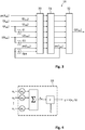
Figur 3 ein Blockschaltbild eines weiteren Ausführungsbeispiels eines künstlichen Neuronalen Netzes der Steuereinrichtung ausFigur 1 , -
Figur 4 ein Blockschaltbild eines Neurons des künstlichen Neuronalen Netzwerks derFiguren 1-3 , -
Figur 5 eine Aktivierungsfunktion für das Neuron ausFigur 4 , -
Figur 6 einen beispielhaften Zusammenhang zwischen der Volumenströmung, dem Motorstrom und der Ventilatordrehzahl des Ventilatorsystems ausFigur 1 , wobei die Linien gleichen Volumenstroms dargestellt sind, die sich mit Linien gleichen Ausgangsdrucks kreuzen, -
Figur 7 einen beispielhaften Zusammenhang zwischen der Ventilatordrehzahl, dem Motorstrom und dem Aussteuergrad bzw. der Motorspannung des Ventilatorsystems ausFigur 1 , -
Figur 8 einen beispielhaften Zusammenhang zwischen der Ventilatordrehzahl, dem Volumenstrom und dem Aussteuergrad bzw. der Spannung des Ventilatorsystems aus Figur 1 und -
Figur 9 Kennlinien einer Kennlinienschar, die beispielhaft den Zusammenhang zwischen dem Volumenstrom und dem Motorstrom des Ventilatorsystems ausFigur 1 veranschaulichen. - In
Figur 1 ist stark schematisiert anhand eines Blockschaltbilds ein Ventilatorsystem 10 veranschaulicht. Das Ventilatorsystem 10 weist eine Steuereinrichtung 11 zur Steuerung oder Regelung eines rückwärtsgekrümmten Radialventilators 12 auf. Der rückwärtsgekrümmte Radialventilator 12 hat einen Motor, beispielsgemäß einen Elektromotor 13, der mit einem Rotor 14 des Radialventilators antriebsverbunden ist. Der Rotor 14 erzeugt bei seiner Drehung eine Gasströmung G, beispielsweise eine Luftströmung, die stromabwärts des Radialventilators 12 bzw. stromabwärts des Ventilatorsystems 10 einen Ausgangsdruck pa und einen Volumenstrom Q aufweist. - Der rückwärtsgekrümmte Radialventilator 12 bzw. der Rotor 14 hat sich zwischen einer radial inneren Kante und einer radial äußeren Kante gekrümmt erstreckende Ventilatorschaufeln 15, die in Drehrichtung regelmäßig verteilt am Rotor 14 angeordnet sind. Die radial innere Kante ist in Drehrichtung betrachtet vor der radial äußeren Kante angeordnet. Die in Drehrichtung weisende Seite jeder Ventilatorschaufel 15 ist konvex und die entgegengesetzte Seite konkav geformt.
- Die Gasströmung G kann durch wenigstens einen Strömungsparameter beschrieben werden, beispielsweise durch den Ausgangsdruck pa oder den Volumenstrom Q. Zumindest einer der Strömungsparameter und beispielsgemäß der Volumenstrom Q, kann gesteuert oder geregelt werden. Das Steuern oder Regeln des Strömungswerts der Gasströmung G soll beispielsgemäß ohne sensorische Erfassung erfolgen, insbesondere ohne das Verwenden eines Volumenstromsensors und/oder eines Drucksensors.
- Beim Ausführungsbeispiel soll mittels der Steuereinrichtung 11 der Strömungsparameter der Gasströmung G auf einen Wert geregelt werden, der durch einen Strömungssollwert B vorgegeben wird. Der Strömungssollwert B ist beispielsgemäß ein Volumenstromsollwert und der Volumenstrom Q bildet somit die Regelgröße. Der Volumenstromistwert wird nicht sensorisch erfasst, sondern in der Steuereinrichtung 11 unter Verwendung eines künstlichen Neuronalen Netzes 19 ermittelt. Basierend auf dem durch das künstliche Neuronale Netz 19 ermittelten Strömungsistwert, hier dem Volumenstromistwert, kann durch Differenzbildung mit dem Strömungssollwert B eine Regeldifferenz D berechnet und einem Regler 20 der Steuereinrichtung 11 zugeführt werden. Der Regler 20 kann daraufhin einen oder mehrere Betriebsparameter des Elektromotors 13, beispielsweise den Motorstrom I oder die Motorspannung U verändern, um die Regeldifferenz D zu minimieren und idealerweise zu eliminieren.
- Durch das Profil der Ventilatorschaufeln 15 entsteht eine den Zusammenhang zwischen dem Motorstrom I und dem Volumenstrom Q beschreibende Kennlinie des rückwärtsgekrümmten Radialventilators 12, wie sie in
Figur 9 veranschaulicht ist. Der Verlauf ist nicht linear und weist ein Maximum auf. Die Kennlinie verschiebt sich mit zunehmender Ventilatordrehzahl in Richtung höherer Werte des Motorstroms I bei gleichbleibendem Volumenstrom Q. Aufgrund des gekrümmten, parabelähnlichen Verlaufs, kann die Bestimmung des Motorstroms I des Elektromotors 13 und der Ventilatordrehzahl n (Drehzahl des Elektromotors 13 oder Rotors 14) keine eindeutige Zuordnung zu dem erzeugten Volumenstrom Q der Gasströmung G getroffen werden, da der Arbeitspunkt nicht eindeutig ist. Dieser nicht eindeutige Zusammenhang ist durch die jeweils einen konstanten Motorstromwert beschreibenden gestrichelten Linien inFigur 9 veranschaulicht, die jeweils zwei Schnittpunkte mit einer zugeordneten Kennlinie haben. - Zur weiteren Veranschaulichung des Betriebsverhaltens des rückwärtsgekrümmten Radialventilators 12 sind in den
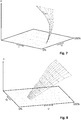
Figuren 6-8 weitere räumliche Kennflächen veranschaulicht.Figur 6 zeigt den Zusammenhang zwischen dem erzeugten Volumenstrom Q, dem Ausgangsdruck pa, dem Motorstrom I und der Ventilatordrehzahl n. Linien konstanten Ausgangsdrucks pa kreuzen inFigur 6 die Linien konstanten Volumenstroms Q. InFigur 7 ist der Zusammenhang zwischen der Ventilatordrehzahl n, dem Motorstrom I und einer Aussteuerung des Elektromotors 13 zwischen 0% und 100% veranschaulicht, wobei die Aussteuerung mit steigender Motorspannung U zunimmt.Figur 8 veranschaulicht den Zusammenhang zwischen der Ventilatordrehzahl n, dem Volumenstrom Q der Gasströmung G und der Aussteuerung des Elektromotors 13. - Zur Erfassung der Ventilatordrehzahl n kann optional ein Drehzahlsensor 21 vorhanden sein, der vorzugsweise aber entfällt. Optional kann auch wenigstens ein weiterer Sensor 22 vorhanden sein, um die Umgebungsbedingungen oder andere Einflussparameter zu erfassen, beispielsweise die Luftfeuchtigkeit h und/oder den Eingangsdruck pe, der beispielsweise dem Luftdruck in der Umgebung entsprechen kann. Anstelle der sensorischen Erfassung des Eingangsdruckes pe kann dieser auch anderweitig ermittelt werden, beispielsweise durch eine Berechnung abhängig vom geographischen Installationsort des Ventilatorsystems 10, insbesondere der geographischen Höhe über dem Meeresspiegel.
- Dem künstlichen Neuronalen Netz 19 werden Betriebsparameter des Radialventilators 12 und insbesondere des Elektromotors 13 übermittelt. Einer der Betriebsparameter bildet eine Stellgröße und ein weiterer Betriebsparameter bildet eine Systemistgröße. Als Stellgröße kann die Motorspannung U und als Systemistgröße der Motorstrom I verwendet werden oder alternativ auch umgekehrt. Diese Systemistgröße kann berechnet, geschätzt oder gemessen werden. Als Motorspannung U kann beispielsweise der mittels der Steuereinrichtung 11 ausgegebene Motorspannungssollwert verwendet werden, so dass auf eine Messung des Motorspannungsistwertes verzichtet werden kann. Die Ventilatordrehzahl n bzw. deren Änderung wird beispielsgemäß indirekt überwacht, z.B. über den Motorstrom I. Alternativ oder zusätzlich kann die Ventilatordrehzahl n auch mittels des Drehzahlsensors 21 sensorisch erfasst und an die Steuereinrichtung 11 übermittelt werden.
- Optional können weitere Eingangsgrößen für das künstliche Neuronale Netz 19 der Eingangsdruck pe oder die Luftfeuchtigkeit h sein.
- In der Steuereinrichtung 11 bzw. dem künstlichen Neuronalen Netz 19 werden nicht nur lediglich die jeweils aktuellen Werte der Motorspannung U und des Motorstroms I berücksichtigt, sondern auch deren zeitliches Verhalten bzw. zeitlicher Verlauf. Dazu können beispielsweise mehrere zu unterschiedlichen Zeitpunkten erfasste Werte der Motorspannung U und des Motorstroms I als Eingangsgrößen in das künstliche Neuronale Netz 19 eingegeben werden (
Figur 2 ). Die Differenz dieser Werte geteilt durch den zeitlichen Abstand der Erfassung ergibt - zumindest näherungsweise - einen Steigungswert, der die zeitliche Änderung beschreibt. - Alternativ kann mit Hilfe von Differenziergliedern 23 eine zeitliche Ableitung erzeugt werden, beispielsweise die Motorstromänderung dI und optional zusätzlich die Ventilatordrehzahländerung dn, die jeweils die zeitlichen Ableitungen erster Ordnung des Motorstroms I bzw. der Ventilatordrehzahl n darstellen (
Figur 3 ). Zusätzlich oder alternativ können auch zeitliche Ableitungen höherer Ordnung ermittelt und berücksichtigt werden. Diese Ausgestaltung eignet sich insbesondere dann, wenn die Betriebsparameter zeitkontinuierlich erfasst werden. InFigur 3 sind die aktuellen Werte durch den aktuellen Messzeitpunkt takt veranschaulicht. - In
Figur 2 ist schematisch die Möglichkeit dargestellt, dass die Betriebsparameter zeitdiskret jeweils in einem Zeitintervall T erfasst werden. Der aktuelle Zeitpunkt ist durch das Zeitintervall kT angegeben. Das vorherige Zeitintervall ist beschrieben durch (k-1)T. Für die Eingangsgrößen wird das Zeitverhalten berücksichtig. Der Motorstrom I sowie die Motorspannung U werden jeweils zum aktuellen Zeitintervall als aktueller Motorstromwert I(kT) und als aktueller Motorspannungswert U(kT) an das künstliche Neuronale Netz 19 übergeben. Außerdem werden mindestens ein vorangegangener Motorstrom I((k-1)T) und mindestens ein vorangegangener Motorspannungswert U((k-1)T) an das künstliche Neuronale Netz 19 übergeben, um das Zeitverhalten zu berücksichtigen. - Wie bereits erläutert, können auch weitere Eingangswerte an das künstliche Neuronale Netz übergeben werden, wie es in den
Figuren 2 und3 veranschaulicht ist. Alle Eingangsgrößen können zusätzlich zur Übergabe des jeweils aktuellen Wertes auch im Hinblick auf ihr Zeitverhalten übergeben werden, beispielsweise indem ein vorangegangener Wert zu einem vorangegangenen Zeitpunkt übermittelt wird (Figur 2 ) oder indem mittels eines Differenziergliedes 23 die zeitliche Ableitung ermittelt wird (Figur 3 ). In beiden Fällen liegen dem künstlichen Neuronalen Netz 19 Erkenntnisse über das Zeitverhalten vor. - Das künstliche Neuronale Netz 19 ist in den
Figuren 2 und3 lediglich schematisch veranschaulicht. Es weist eine Eingangsschicht 30, wenigstens eine verdeckte Schicht 31 und eine Ausgangsschicht 32 auf. Jeder dieser Schichten 30, 31, 32 des künstlichen Neuronalen Netzes 19 kann abhängig von der konkreten Ausgestaltung eine beliebige Anzahl an Neuronen 33 (Figur 4 ) aufweisen. In der Eingangsschicht 30 sind beispielsweise so viele Neuronen 33 vorhanden, wie Eingangsgrößen an die Eingangsschicht 30 übermittelt werden. Beim Ausführungsbeispiel ist für jeden aktuellen Wert einer Eingangsgröße ein Neuron 33 vorhanden und für jeden zugeführten vorangegangenen Wert (Figur 2 ) oder für jede zugeführte zeitliche Ableitung (Figur 3 ) ist ein zusätzliches Neuron 33 in der Eingangsschicht 30 vorhanden. Beispielsgemäß sind mindestens vier oder fünf Neuronen in der Eingangsschicht 30 vorhanden. - Jedem Neuron 33 in der Eingangsschicht 30 wird zumindest eine der folgenden Eingangsgrößen übermittelt: der aktuelle Wert des Motorstroms I(kT), I(takt) und/oder der aktuelle Wert der Ventilatordrehzahl n(kT), n(takt), der aktuelle Wert der Motorspannung U(kT), U(takt), der aktuelle Wert des Ausgangsdrucks pa, der vorangegangene Wert I((k-1)T) oder die zeitliche Ableitung dI des Motorstroms I und/oder der vorangegangene Wert n((k-1)T) oder die zeitliche Ableitung dn der Ventilatordrehzahl n. Beispielsgemäß wird auch der vorangegangene Wert U((k-1)T) oder die zeitliche Ableitung dU der Motorspannung U an die Eingangsschicht 30 übermittelt. Optional zusätzlich kann auch der vorangegangene Wert pa((k-1)T) des Ausgangsdruckes (
Figur 2 ) oder die zeitliche Ableitung dpa des Ausgangsdruckes pa (Figur 3 ) an die Eingangsschicht 30 übermittelt werden. Das Zuführen des Eingangsdruckes pe sowie der Luftfeuchtigkeit h ist ebenfalls optional. - Wie es in
Figur 4 dargestellt ist, wird jedem Neuron 33 wenigstens ein Wert aus einer anderen Schicht und/oder wenigstens eine der genannten Eingangsgrößen an jeweils einem Neuroneneingang als Neuroneneingangswert x1 bis xn zugeführt. Die Neuroneneingangswerte x1 bis xn werden über jeweils einen zugeordneten Gewichtungsfaktor w1 bis wn gewichtet und aufsummiert, wodurch eine gewichtete Summe xw gebildet wird. Die gewichtete Summe wird einer Aktivierungsfunktion F des Neurons 33 übermittelt. Die Aktivierungsfunktion F hängt auch von einem Schwellenwert S ab. Konkret wird als Neuronenausgangswert y der Wert der Aktivierungsfunktion F ausgegeben, abhängig von der Differenz der gewichteten Summe xw minus dem Schwellenwert S: y = xw - S. Über den Schwellenwert S wird vorgegeben, wann das Neuron 33 feuert. - Alternativ zu der Berücksichtigung des Schwellenwerts S als Eingangsparameter in der Aktivierungsfunktion F, können auch sogenannte On-Neuronen verwendet werden, bei denen ein Schwellenwert S als Neuroneneingangswert x0 bei der Bildung der gewichteten Summe xw berücksichtigt wird.
- In
Figur 5 ist lediglich beispielhaft eine Möglichkeit für eine Aktivierungsfunktion F veranschaulicht. Beispielsgemäß wird als Aktivierungsfunktion F ein Rectifier (ReLU) gewählt. Es können auch andere bekannte Aktivierungsfunktionen für Neuronen 33 verwendet werden, die vorzugsweise nicht linear sind. Beim Ausführungsbeispiel wird der Neuronenausgangswert y auf einen Maximalwert Fmax der Aktivierungsfunktion F begrenzt, beispielsweise 6. Durch die Begrenzung auf den Maximalwert können selten auftretende Merkmale beim Lernen des künstlichen Neuronalen Netzes 19 besser berücksichtigt werden. - Das künstliche Neuronale Netz 19 wird anhand bekannter Parameter und Daten trainiert und kann nach dem Training zur Steuerung oder Regelung verwendet werden. Während des Betriebs ist es möglich, das künstliche Neuronale Netz 19 zu aktualisieren. Ein kontinuierliches Lernen ist bei der bevorzugten Ausführung des Ventilatorsystems 10 nicht vorgesehen, da vorzugsweise keine Sensoren 21, 22 vorhanden sind.
- Wenigstens ein ermittelter Neuronenausgangswert y kann aus einer nachfolgenden Schicht in eine vorhergehende Schicht zurückgeführt werden. Die Rückkopplung kann intern, innerhalb des künstlichen Neuronalen Netzes 19 oder auch extern, also außerhalb des künstlichen Neuronalen Netzes 19, erfolgen. Das künstliche Neuronale Netz 19 kann beispielsweise als rekurrentes Neuronales Netz ausgestaltet sein. Beispielsgemäß wird in einer verdeckten Schicht 31 oder alternativ auch in der Ausgangsschicht 32 wenigstens ein Strömungsistwert ermittelt, der in eine vorhergehende Schicht zurückgekoppelt werden kann, insbesondere in die Eingangsschicht 30. Bei den in den
Figuren 2 und3 veranschaulichten Ausführungsbeispielen wird innerhalb wenigstens einer verdeckten Schicht 31 ein aktueller Wert für den Ausgangsdruck pa ermittelt und als Eingangsgröße an die Eingangsschicht 30 zurückgekoppelt. - Durch die Rückkopplung des Ausgangsdruckes pa auf die Eingangsschicht 30 ist eine gute Stabilität der Regelung erreicht, auch wenn sich die zugeführten anderen Eingangsgrößen nicht ändern. Außerdem kann unter Verwendung des ermittelten aktuellen Ausgangsdrucks bei der erneuten Berechnung des Ausgangsdrucks eine Mittelwertermittlung erfolgen.
- Wenn sich die Strömungsverhältnisse der Gasströmung G aufgrund äußerer Einflüsse ändern, reagiert das Ventilatorsystem mit einer Änderung der Ventilatordrehzahl n, die in der Änderung des Motorstromes I (Systemistgröße) erkannt wird. Das trainierte künstliche Neuronale Netz 19 ermittelt den dazugehörigen Volumenstromistwert des Volumenstroms Q. Der Regler 20 passt daraufhin die Motorspannung U (Stellgröße) an, um die Regeldifferenz D zu minimieren, die wiederum dem künstlichen Neuronale Netz 19 zurückgeführt wird.
- Der Regler 20 kann als Softwaremodul und/oder Hardwaremodul realisiert sein. Das Ermitteln der Regeldifferenz und der Stellgröße durch den Regler 20 erfolgt beispielsgemäß außerhalb des künstlichen Neuronalen Netzes 19 und kann optional auch innerhalb des künstlichen Neuronalen Netzes 19 durchgeführt werden.
- Beim Trainieren können sehr einfach, beispielsweise unter Verwendung einer Venturi-Düse zur Differenzdruckbestimmung, unterschiedliche Ausgangsdrücke pa eingestellt und das künstliche Neuronale Netz 19 basierend auf dem Wert des Ausgangsdruckes pa gelernt werden, ohne den Volumenstromistwert Q messen zu müssen. Als die Strömungsverhältnisse beschreibender Parameter für das Trainieren bzw. Lernen wird daher nicht der Volumenstrom Q, sondern der Ausgangsdruck pa verwendet, so dass auf einen Volumenstromsensor verzichtet werden kann. Der Einsatz eines Volumenstromsensors beim Training kann im Bedarfsfall erfolgen, um genauere Trainingsergebnisse zu erzielen. Basierend auf diesem Trainieren kann das künstliche Neuronale Netz 19 hinreichend genau an die Anforderungen adaptiert werden, so dass sich bei der Inbetriebnahme gute Regelergebnisse für die Regelung des Volumenstroms Q ergeben.
- Das künstliche Neuronale Netz 19 reagiert beim Betrieb des Ventilatorsystems 10 auch auf äußere Veränderungen, die Einfluss auf den Betrieb haben und beispielsweise eine Änderung der Ventilatordrehzahl n erzeugen. In der Steuereinrichtung 11 können Vergleichsmodelle für den Zustand des künstlichen Neuronalen Netzes 19 abgelegt sein, die einer bekannten Störgröße oder einem bekannten Umgebungsparameter zugeordnet sind. Durch Vergleich des aktuellen Zustands des künstlichen Neuronalen Netzes 19 mit den Vergleichsmodellen kann in der Steuereinrichtung 11 somit auch erkannt werden, ob und welche Veränderungen in der Umgebung oder der Anlage eingetreten sind. Beispielsweise kann eine zunehmende Beladung eines Filters bzw. das Verstopfen des Filters erkannt werden. Eine solche Änderung ist im Hinblick auf das zeitliche Verhalten nicht abrupt, sondern langsamer verglichen mit anderen äußeren Einflüssen. Durch die Berücksichtigung der zeitlichen Änderung bzw. zeitlich aufeinanderfolgender Werte zumindest für die Systemistgröße und gegebenenfalls eine oder mehrere weitere Eingangsgrößen im künstlichen Neuronalen Netz 19 lassen sich Rückschlüsse auf die Art des äußeren Einflusses ziehen. Beispielsweise kann das Öffnen oder Schließen einer Tür oder einer Klappe im Ansaugvolumen und/oder im Abströmvolumen durch eine plötzliche Änderung des Betriebszustandes (z.B. der Ventilatordrehzahl n) des Ventilatorsystems 10 erkannt werden.
- Aufgrund der Berücksichtigung des Zeitverhaltens, insbesondere des Motorstroms I und/oder der Ventilatordrehzahl n und/oder der Motorspannung U, kann der Arbeitspunkt eindeutig bestimmt und zum Beispiel einem Motorstrom I eindeutig ein aktueller Volumenstrom Q zugeordnet werden. Für die Darstellung in
Figur 9 bedeutet dies, dass die Kennlinie aus der Kennlinienschar anhand der aktuellen Ventilatordrehzahl n (gemessen oder berechnet aus Motorstrom I oder Motorspannung U) ausgewählt wird. Anhand der Änderung des Motorstroms I kann erkannt werden, ob der Motorstrom I ansteigt oder fällt. Abhängig davon ist der aktuelle Arbeitspunkt im ansteigenden Teil der Kennlinie bis zum Maximum des Motorstromes I oder im abfallenden Teil der Kennlinie bei Volumenstromwerten, die größer sind als der durch das Maximum des Motorstroms I beschriebene Volumenstromwert. - Die Erfindung betrifft ein Verfahren zum Betreiben eines Ventilatorsystems 10 sowie ein solches Ventilatorsystem 10. Das Ventilatorsystem 10 hat eine Steuereinrichtung 11 mit einem künstlichen Neuronalen Netz 19. Die Steuereinrichtung 11 steuert ein Elektromotor 13 eines rückwärtsgekrümmten Radialventilators 12. Der Radialventilator 12 erzeugt eine Gasströmung G, die durch einen Strömungsistwert, insbesondere den Volumenstromistwert Q, gekennzeichnet ist. Der Strömungsistwert wird nicht sensorisch erfasst, sondern durch das künstliche Neuronale Netz 19 abhängig von Eingangsgrößen durch das künstliche Neuronale Netz 19 ermittelt und basierend darauf wird durch die Steuereinrichtung 11 der Elektromotor 13 gesteuert oder geregelt. Einer Eingangsschicht 30 des künstlichen Neuronalen Netzes 19 werden der Motorstrom I und die Motorspannung U zugeführt sowie deren zeitliche Verhalten, die durch die zeitliche Ableitung (beispielsweise Gradient erster Ordnung) gebildet werden können oder durch wenigstens einen vorangegangenen Wert zu einem früheren, vorangegangenen Zeitpunkt. Es ist insbesondere vorteilhaft, wenn das künstliche Neuronale Netz 19 einen Ausgangsdruckistwert ermittelt und diesen intern oder extern als Eingangsgröße an die Eingangsschicht 30 zurückführt. Weitere Eingangsgrößen können zusätzlich optional berücksichtigt werden.
-
- 10
- Ventilatorsystem
- 11
- Steuereinrichtung
- 12
- Radialventilator
- 13
- Motor
- 14
- Rotor
- 15
- Ventilatorschaufel
- 19
- künstliches Neuronales Netz
- 20
- Regler
- 21
- Drehzahlsensor
- 22
- Sensor
- 23
- Differenzierglied
- 30
- Eingangsschicht
- 31
- verdeckte Schicht
- 32
- Ausgangsschicht
- 33
- Neuron
- B
- Strömungssollwert
- D
- Regeldifferenz
- dI
- Motorstromänderung
- dU
- Motorspannungsänderung
- dpa
- Ausgangsdruckänderung
- F
- Aktivierungsfunktion
- Fmax
- Maximalwert der Aktivierungsfunktion
- G
- Gasströmung
- h
- Luftfeuchtigkeit
- I
- Motorstrom
- kT
- aktueller Zeitpunkt (zeitdiskret)
- n
- Ventilatordrehzahl
- pa
- Ausgangsdruck
- pe
- Eingangsdruck
- Q
- Volumenstrom
- S
- Schwellenwert
- takt
- aktueller Zeitpunkt (zeitkontinuierlich)
- U
- Motorspannung
- wi
- Gewichtungsfaktor i (i=1-n)
- xi
- Neuroneneingangswert i (i=1-n)
- xw
- gewichtete Summe
- y
- Neuronenausgangswert
Claims (16)
- Verfahren zum Betreiben eines Ventilatorsystems (10) aufweisend eine Steuereinrichtung (11) und einen rückwärtsgekrümmten Radialventilator (12) mit einem Motor (13) und einem vom Motor (13) angetriebenen Rotor (14), wobei das Ventilatorsystem (10) dazu eingerichtet ist, eine Gasströmung (G) zu erzeugen, die durch wenigstens einen Strömungsistwert (pa(kT), Q(kT); pa (takt), Q(takt)) charakterisiert ist, wobei das Verfahren umfasst:- Bestimmen eines den Betriebszustand des Motors (13) des Radialventilators (12) beschreibenden Betriebsparameters (U(kT); U(takt)) als Stellgröße,- kontinuierliches oder zeitdiskretes Ermitteln wenigstens eines den Betriebszustand des Motors (13) des Radialventilators (12) beschreibenden Betriebsparameters (I(kT); I(takt)) als wenigstens eine Systemistgröße,- Übergeben der Stellgröße (U(kT); U(takt)) und der Systemistgröße (I(kT); I(takt)) an ein künstliches Neuronales Netz (19) der Steuereinrichtung (11),- Ermitteln des wenigstens eines Strömungsistwertes (Q(kT), Q(takt)) durch das künstliche Neuronale Netz (19) basierend auf der Stellgröße (U(kT); U(takt)) und der Systemistgröße (I(kT); I(takt)) und der zeitlichen Änderung (I((k-1)T); dI) der Systemistgröße(I((k-1)T); dI),- Prüfen, ob die Stellgröße (U(kT); U(takt)) verändert werden muss, basierend auf dem wenigstens einen ermittelten Strömungsistwert (Q(kT), Q(takt)).
- Verfahren nach Anspruch 1, wobei der Steuereinrichtung (11) einen Regler (20) aufweist, dem die Regeldifferenz (D) zwischen einem vorgegebenen Strömungssollwert (B) und dem Strömungsistwert (Q(kT), Q(takt)) übermittelt wird.
- Verfahren nach Anspruch 1 oder 2, wobei ein Strömungsistwert von dem wenigstens einen im künstlichen Neuronalen Netz (19) ermittelten Strömungsistwert ein Volumenstromistwert (Q(kT), Q(takt)) ist und der Strömungssollwert (B) ein Volumenstromsollwert ist.
- Verfahren nach Anspruch 2 und 3, wobei sich der Volumenstromsollwert während des Betriebs konstant bleibt, um einen konstanten Volumenstrom zu erhalten.
- Verfahren nach einem der vorhergehenden Ansprüche, wobei das künstliche Neuronale Netz (19) eine Eingangsschicht (30) aufweist, der der aktuelle Wert der Systemistgröße (I(kT); I(takt)) und der Stellgröße (U(kT); U(takt)) zum aktuellen Zeitpunkt (kT) sowie ein vorangegangener Wert der Systemistgröße (I((k-1)T)) zu einem vorangegangenen Zeitpunkt ((k-1)T) übermittelt werden.
- Verfahren nach Anspruch 5, wobei der Eingangsschicht (30) zusätzlich ein vorangegangener Wert der Stellgröße (U((k-1)T)) zu einem vorangegangenen Zeitpunkt ((k-1)T) übermittelt wird.
- Verfahren nach einem der vorhergehenden Ansprüche, wobei das künstliche Neuronale Netz (19) eine Eingangsschicht (30) aufweist, der der aktuelle Wert der Systemistgröße ((I(takt))) zum aktuellen Zeitpunkt (takt) sowie eine zeitliche Änderung der Systemistgröße (dI) zum aktuellen Zeitpunkt (takt), übermittelt werden.
- Verfahren nach Anspruch 7, wobei der Eingangsschicht (30) zusätzlich eine zeitliche Änderung der Stellgröße (dU) zum aktuellen Zeitpunkt (takt), übermittelt wird.
- Verfahren nach einem der vorhergehenden Ansprüche, wobei ein Strömungsistwert von dem wenigstens einen im künstlichen Neuronalen Netz (19) ermittelten Strömungsistwert ein Ausgangsdruckistwert (pa(kT), pa(takt)) ist.
- Verfahren nach einem der vorhergehenden Ansprüche, wobei ein Strömungsistwert (pa(kT), pa(takt)) von dem wenigstens einen im künstlichen Neuronalen Netz (19) ermittelten Strömungsistwert (pa(kT), pa(takt)) zu einer Eingangsschicht (30) des künstlichen Neuronalen Netzes (19) zurückgeführt wird.
- Verfahren nach Anspruch 9 und 10, wobei der Ausgangsdruckistwert (pa(kT), pa(takt)) zur Eingangsschicht (30) zurückgeführt wird.
- Verfahren nach einem der vorhergehenden Ansprüche, wobei das künstliche Neuronale Netz (19) Neuronen (33) aufweist und wobei jedes Neuron (33) eine Aktivierungsfunktion (F) aufweist.
- Verfahren nach Anspruch 12, wobei die Aktivierungsfunktion (F) durch einen Rectifier gebildet.
- Verfahren nach Anspruch 12 oder 13, wobei die Aktivierungsfunktion (F) auf einen Maximalwert (Fmax) begrenzt ist.
- Verfahren nach einem der vorhergehenden Ansprüche, wobei zumindest eine von der wenigstens einen Systemistgröße von der Ventilatordrehzahl (n) abhängt oder die Ventilatordrehzahl (n) ist und wobei Ventilatordrehzahl (n) indirekt ermittelt oder direkt mittels eines Drehzahlsensors (21) erfasst werden kann.
- Ventilatorsystem (10) aufweisend eine Steuereinrichtung (11) und einen rückwärtsgekrümmten Radialventilator (12) mit einem Motor (13) und einem vom Motor (13) angetriebenen Rotor (14), wobei die Steuereinrichtung (11) dazu eingerichtet ist, das Verfahren nach einem der vorhergehenden Ansprüche auszuführen.
Applications Claiming Priority (1)
| Application Number | Priority Date | Filing Date | Title |
|---|---|---|---|
| DE102020114339.7A DE102020114339A1 (de) | 2020-05-28 | 2020-05-28 | Verfahren zum Betreiben eines Ventilatorsystems und Ventilatorsystem mit einem rückwärtsgekrümmten Radialventilator |
Publications (2)
| Publication Number | Publication Date |
|---|---|
| EP3916236A1 true EP3916236A1 (de) | 2021-12-01 |
| EP3916236B1 EP3916236B1 (de) | 2023-03-01 |
Family
ID=76098872
Family Applications (1)
| Application Number | Title | Priority Date | Filing Date |
|---|---|---|---|
| EP21175726.5A Active EP3916236B1 (de) | 2020-05-28 | 2021-05-25 | Verfahren zum betreiben eines ventilatorsystems und ventilatorsystem mit einem rückwärtsgekrümmten radialventilator |
Country Status (4)
| Country | Link |
|---|---|
| US (1) | US11746794B2 (de) |
| EP (1) | EP3916236B1 (de) |
| CN (1) | CN113738662B (de) |
| DE (1) | DE102020114339A1 (de) |
Families Citing this family (3)
| Publication number | Priority date | Publication date | Assignee | Title |
|---|---|---|---|---|
| DE102020118251A1 (de) * | 2020-07-10 | 2022-01-13 | Ebm-Papst Mulfingen Gmbh & Co. Kg | Verfahren und Ventilatorsystem zur Ermittlung des Zustands eines Filters in einer Ventilatoreinheit |
| TWI838016B (zh) * | 2022-12-16 | 2024-04-01 | 宏碁股份有限公司 | 電子裝置與風扇轉速調整方法 |
| DE102024120729A1 (de) * | 2024-07-22 | 2026-01-22 | Ebm-Papst Mulfingen Gmbh & Co. Kg | Verfahren und Vorrichtung zur Erkennung von ordnungsgemäßen und/oder nicht ordnungsgemäßen Installations- und/oder Montagezuständen eines Ventilators |
Citations (5)
| Publication number | Priority date | Publication date | Assignee | Title |
|---|---|---|---|---|
| DE29516268U1 (de) * | 1995-10-13 | 1996-02-22 | Oppermann Regelgeräte GmbH, 70567 Stuttgart | Leistungsregelung für ein Gebläse |
| US5736823A (en) * | 1994-05-27 | 1998-04-07 | Emerson Electric Co. | Constant air flow control apparatus and method |
| US20170248149A1 (en) * | 2014-10-28 | 2017-08-31 | Panasonic Intellectual Property Managemet Co., Ltd. | Ventilation device |
| DE102018104396A1 (de) * | 2018-02-27 | 2019-08-29 | Ebm-Papst Mulfingen Gmbh & Co. Kg | Parameterkonstanz |
| US20190376715A1 (en) * | 2018-06-11 | 2019-12-12 | Broan-Nutone Llc | Ventilation system with automatic flow balancing derived from a neural network and methods of use |
Family Cites Families (24)
| Publication number | Priority date | Publication date | Assignee | Title |
|---|---|---|---|---|
| JPH09317544A (ja) * | 1996-05-30 | 1997-12-09 | Yamaha Motor Co Ltd | エンジンにおける制御対象の学習制御方法 |
| SE9703758D0 (sv) * | 1997-10-15 | 1997-10-15 | Asea Brown Boveri | Metod och förfarande för processkontroll vid tillverkning av papper, massa eller board |
| DE10112160A1 (de) * | 2001-03-14 | 2002-10-02 | Powitec Intelligent Tech Gmbh | Verfahren und Vorrichtung zur Regelung eines Verbrennungsprozesses |
| US6970857B2 (en) * | 2002-09-05 | 2005-11-29 | Ibex Process Technology, Inc. | Intelligent control for process optimization and parts maintenance |
| JP2004114937A (ja) * | 2002-09-27 | 2004-04-15 | Denso Corp | 車両用空調装置 |
| US8672733B2 (en) * | 2007-02-06 | 2014-03-18 | Nordyne Llc | Ventilation airflow rate control |
| KR100983800B1 (ko) * | 2008-02-19 | 2010-09-27 | (주) 리더스 | 신경회로망을 이용한 간이상수도 모니터링 제어시스템 및그 제어방법 |
| DE102009034369B3 (de) * | 2009-07-23 | 2010-08-26 | Sinitec Vertriebsgesellschaft Mbh | Verfahren zur Anpassung eines Steuersignals zur Vorgabe einer Solldrehzahl eines Lüfters in einem Computersystem sowie entsprechendes Computersystem |
| CN102315809B (zh) * | 2010-07-08 | 2016-11-16 | 德昌电机(深圳)有限公司 | 风扇电机装置、空气流动性调节设备及风量控制方法 |
| CN102011745B (zh) * | 2010-12-31 | 2013-08-07 | 清华大学 | 一种磁悬浮分子泵的神经网络控制系统及方法 |
| US8793004B2 (en) * | 2011-06-15 | 2014-07-29 | Caterpillar Inc. | Virtual sensor system and method for generating output parameters |
| JP6438366B2 (ja) * | 2015-08-28 | 2018-12-12 | ファナック株式会社 | 電動機に対する動作指令を学習する機械学習方法および機械学習装置並びに該機械学習装置を備えた制御装置および電動機装置 |
| DE102015012462B3 (de) * | 2015-09-29 | 2017-03-16 | LUNOS Lüftungstechnik GmbH für Raumluftsysteme | Verfahren und eine Vorrichtung zum sensorlosen Regeln eines mit einem EC-Motor betriebenen Ventilators eines Lüftungsgeräts |
| CN105260572A (zh) * | 2015-11-10 | 2016-01-20 | 四川东方电气自动控制工程有限公司 | 一种风机叶片建模软件调用系统及其调用方法 |
| DE102016115617A1 (de) * | 2016-08-23 | 2018-03-01 | Ebm-Papst Mulfingen Gmbh & Co. Kg | Verfahren zur Volumenstromregelung eines Ventilators |
| CN106779071B (zh) * | 2016-12-19 | 2019-05-03 | 辽宁工程技术大学 | 一种用于矿井通风机的神经网络自适应调速方法 |
| JP6499710B2 (ja) * | 2017-04-20 | 2019-04-10 | ファナック株式会社 | 加減速制御装置 |
| CN108194398B (zh) * | 2017-12-29 | 2019-09-20 | 青岛海信医疗设备股份有限公司 | 风扇控制方法及装置 |
| US11676025B2 (en) * | 2018-05-30 | 2023-06-13 | Robert Bosch Gmbh | Method, apparatus and computer program for generating robust automatic learning systems and testing trained automatic learning systems |
| CN109242147A (zh) * | 2018-08-07 | 2019-01-18 | 重庆大学 | 基于Bp神经网络的信号融合风机状态预测方法 |
| US10731889B2 (en) * | 2019-01-08 | 2020-08-04 | Regal Beloit America, Inc. | Motor controller for electric blowers |
| US11526724B2 (en) * | 2019-08-21 | 2022-12-13 | GM Global Technology Operations LLC | Virtual sensor for estimating online unmeasurable variables via successive time derivatives |
| CN110529419A (zh) * | 2019-09-02 | 2019-12-03 | 苏州贝舒医疗科技有限公司 | 无创呼吸机风机的压力输出控制方法 |
| CN112560338B (zh) * | 2020-12-10 | 2022-03-25 | 东北大学 | 基于自适应深度学习的复杂工业系统智能预报方法、装置、设备及存储介质 |
-
2020
- 2020-05-28 DE DE102020114339.7A patent/DE102020114339A1/de not_active Withdrawn
-
2021
- 2021-05-25 EP EP21175726.5A patent/EP3916236B1/de active Active
- 2021-05-26 US US17/331,271 patent/US11746794B2/en active Active
- 2021-05-28 CN CN202110593165.4A patent/CN113738662B/zh active Active
Patent Citations (5)
| Publication number | Priority date | Publication date | Assignee | Title |
|---|---|---|---|---|
| US5736823A (en) * | 1994-05-27 | 1998-04-07 | Emerson Electric Co. | Constant air flow control apparatus and method |
| DE29516268U1 (de) * | 1995-10-13 | 1996-02-22 | Oppermann Regelgeräte GmbH, 70567 Stuttgart | Leistungsregelung für ein Gebläse |
| US20170248149A1 (en) * | 2014-10-28 | 2017-08-31 | Panasonic Intellectual Property Managemet Co., Ltd. | Ventilation device |
| DE102018104396A1 (de) * | 2018-02-27 | 2019-08-29 | Ebm-Papst Mulfingen Gmbh & Co. Kg | Parameterkonstanz |
| US20190376715A1 (en) * | 2018-06-11 | 2019-12-12 | Broan-Nutone Llc | Ventilation system with automatic flow balancing derived from a neural network and methods of use |
Also Published As
| Publication number | Publication date |
|---|---|
| CN113738662B (zh) | 2024-05-24 |
| EP3916236B1 (de) | 2023-03-01 |
| US20210372417A1 (en) | 2021-12-02 |
| DE102020114339A1 (de) | 2021-12-02 |
| US11746794B2 (en) | 2023-09-05 |
| CN113738662A (zh) | 2021-12-03 |
Similar Documents
| Publication | Publication Date | Title |
|---|---|---|
| EP3916236B1 (de) | Verfahren zum betreiben eines ventilatorsystems und ventilatorsystem mit einem rückwärtsgekrümmten radialventilator | |
| DE69706986T2 (de) | Zugehörigkeitsfunktionen ändernder adaptiver fuzzy-regler | |
| DE69823271T2 (de) | Verbesserter adaptiver Durchflussregler | |
| DE69518965T2 (de) | Mehrgrössen-/nichtlineare Prozesssteuerung | |
| EP2145112B1 (de) | Einrichtung und verfahren zur störungsüberwachung | |
| DE69101216T2 (de) | Verfahren und vorrichtung zur regelung der luftmenge in einem rohrleitungsnetz. | |
| DE4433593B4 (de) | Verfahren zur Regelung eines Extruders und Vorrichtung dazu | |
| DE69911306T2 (de) | Verfahren und Vorrichtung zur Regelung eines Leitungsnetzes | |
| DE69733114T2 (de) | Verfahren zur Erzeugung und Massstabsänderung der Geschwindigkeitsprofile für Türen einen Fahrkorbes | |
| DE10122776A1 (de) | Anordnung und Verfahren zur Steuerung eines Ventils | |
| EP4185928A1 (de) | Stellungsregler selbstbewertung für digitalen zwilling | |
| DE102011012211A1 (de) | Leistungsoptimiertes Betreiben einer elektromotorisch angetriebenen Pumpe durch Mitkopplung | |
| EP4179265B1 (de) | Verfahren und ventilatorsystem zur ermittlung eines aktuellen arbeitspunktes einer ventilatoreinheit | |
| EP3203330B1 (de) | Softsensor zur identifikation und regelung oder steuerung eines lüftungssystems | |
| EP3881141A1 (de) | Verfahren und eine vorrichtung zum sensorlosen bestimmen des volumenstromes und druckes | |
| DE102019204934A1 (de) | Verfahren zum Regeln eines Elektromotors, Regeleinrichtung sowie entsprechende Systeme | |
| EP0223207B1 (de) | Einrichtung und Verfahren zum Regeln eines Turbokompressors zur Verhinderung des Pumpens | |
| DE102022133793A1 (de) | Verfahren zur Diagnose einer Prozessventil-Baueinheit und Diagnoseeinrichtung | |
| DE102013220904C5 (de) | Verfahren und System zur Regelung einer Antriebseinheit | |
| EP3707386B1 (de) | Parameterkonstanz | |
| DE102007062173A1 (de) | Verfahren zum Betreiben einer Brennkraftmaschine und Steuer- oder Regelrichtung für eine Brennkraftmaschine | |
| DE69127368T2 (de) | Vorrichtung zur Steuerung von Laborabzugschränken | |
| DE19624301B4 (de) | Lernverfahren für ein neuronales Netz | |
| EP3879199B1 (de) | Verfahren zur regelung eines in einer luftleitung einer klima- und/oder raumlufttechnischen anlage strömenden volumenstroms sowie system zur regelung eines in einer luftleitung einer klima- und/oder raumlufttechnischen anlage strömenden volumenstroms | |
| DE69428149T2 (de) | Verfahren und Vorrichtung zur Aufrechterhaltung einer gewünschten Luftdurchflussmenge durch einen Abzug |
Legal Events
| Date | Code | Title | Description |
|---|---|---|---|
| PUAI | Public reference made under article 153(3) epc to a published international application that has entered the european phase |
Free format text: ORIGINAL CODE: 0009012 |
|
| STAA | Information on the status of an ep patent application or granted ep patent |
Free format text: STATUS: THE APPLICATION HAS BEEN PUBLISHED |
|
| AK | Designated contracting states |
Kind code of ref document: A1 Designated state(s): AL AT BE BG CH CY CZ DE DK EE ES FI FR GB GR HR HU IE IS IT LI LT LU LV MC MK MT NL NO PL PT RO RS SE SI SK SM TR |
|
| B565 | Issuance of search results under rule 164(2) epc |
Effective date: 20211021 |
|
| STAA | Information on the status of an ep patent application or granted ep patent |
Free format text: STATUS: REQUEST FOR EXAMINATION WAS MADE |
|
| 17P | Request for examination filed |
Effective date: 20220421 |
|
| RBV | Designated contracting states (corrected) |
Designated state(s): AL AT BE BG CH CY CZ DE DK EE ES FI FR GB GR HR HU IE IS IT LI LT LU LV MC MK MT NL NO PL PT RO RS SE SI SK SM TR |
|
| GRAP | Despatch of communication of intention to grant a patent |
Free format text: ORIGINAL CODE: EPIDOSNIGR1 |
|
| STAA | Information on the status of an ep patent application or granted ep patent |
Free format text: STATUS: GRANT OF PATENT IS INTENDED |
|
| INTG | Intention to grant announced |
Effective date: 20220927 |
|
| GRAS | Grant fee paid |
Free format text: ORIGINAL CODE: EPIDOSNIGR3 |
|
| GRAA | (expected) grant |
Free format text: ORIGINAL CODE: 0009210 |
|
| STAA | Information on the status of an ep patent application or granted ep patent |
Free format text: STATUS: THE PATENT HAS BEEN GRANTED |
|
| AK | Designated contracting states |
Kind code of ref document: B1 Designated state(s): AL AT BE BG CH CY CZ DE DK EE ES FI FR GB GR HR HU IE IS IT LI LT LU LV MC MK MT NL NO PL PT RO RS SE SI SK SM TR |
|
| REG | Reference to a national code |
Ref country code: GB Ref legal event code: FG4D Free format text: NOT ENGLISH |
|
| REG | Reference to a national code |
Ref country code: CH Ref legal event code: EP Ref country code: AT Ref legal event code: REF Ref document number: 1551151 Country of ref document: AT Kind code of ref document: T Effective date: 20230315 |
|
| REG | Reference to a national code |
Ref country code: DE Ref legal event code: R096 Ref document number: 502021000463 Country of ref document: DE |
|
| REG | Reference to a national code |
Ref country code: IE Ref legal event code: FG4D Free format text: LANGUAGE OF EP DOCUMENT: GERMAN |
|
| REG | Reference to a national code |
Ref country code: NL Ref legal event code: FP |
|
| P01 | Opt-out of the competence of the unified patent court (upc) registered |
Effective date: 20230516 |
|
| REG | Reference to a national code |
Ref country code: LT Ref legal event code: MG9D |
|
| PG25 | Lapsed in a contracting state [announced via postgrant information from national office to epo] |
Ref country code: RS Free format text: LAPSE BECAUSE OF FAILURE TO SUBMIT A TRANSLATION OF THE DESCRIPTION OR TO PAY THE FEE WITHIN THE PRESCRIBED TIME-LIMIT Effective date: 20230301 Ref country code: NO Free format text: LAPSE BECAUSE OF FAILURE TO SUBMIT A TRANSLATION OF THE DESCRIPTION OR TO PAY THE FEE WITHIN THE PRESCRIBED TIME-LIMIT Effective date: 20230601 Ref country code: LV Free format text: LAPSE BECAUSE OF FAILURE TO SUBMIT A TRANSLATION OF THE DESCRIPTION OR TO PAY THE FEE WITHIN THE PRESCRIBED TIME-LIMIT Effective date: 20230301 Ref country code: LT Free format text: LAPSE BECAUSE OF FAILURE TO SUBMIT A TRANSLATION OF THE DESCRIPTION OR TO PAY THE FEE WITHIN THE PRESCRIBED TIME-LIMIT Effective date: 20230301 Ref country code: HR Free format text: LAPSE BECAUSE OF FAILURE TO SUBMIT A TRANSLATION OF THE DESCRIPTION OR TO PAY THE FEE WITHIN THE PRESCRIBED TIME-LIMIT Effective date: 20230301 Ref country code: ES Free format text: LAPSE BECAUSE OF FAILURE TO SUBMIT A TRANSLATION OF THE DESCRIPTION OR TO PAY THE FEE WITHIN THE PRESCRIBED TIME-LIMIT Effective date: 20230301 |
|
| PG25 | Lapsed in a contracting state [announced via postgrant information from national office to epo] |
Ref country code: SE Free format text: LAPSE BECAUSE OF FAILURE TO SUBMIT A TRANSLATION OF THE DESCRIPTION OR TO PAY THE FEE WITHIN THE PRESCRIBED TIME-LIMIT Effective date: 20230301 Ref country code: PL Free format text: LAPSE BECAUSE OF FAILURE TO SUBMIT A TRANSLATION OF THE DESCRIPTION OR TO PAY THE FEE WITHIN THE PRESCRIBED TIME-LIMIT Effective date: 20230301 Ref country code: GR Free format text: LAPSE BECAUSE OF FAILURE TO SUBMIT A TRANSLATION OF THE DESCRIPTION OR TO PAY THE FEE WITHIN THE PRESCRIBED TIME-LIMIT Effective date: 20230602 Ref country code: FI Free format text: LAPSE BECAUSE OF FAILURE TO SUBMIT A TRANSLATION OF THE DESCRIPTION OR TO PAY THE FEE WITHIN THE PRESCRIBED TIME-LIMIT Effective date: 20230301 |
|
| PG25 | Lapsed in a contracting state [announced via postgrant information from national office to epo] |
Ref country code: SM Free format text: LAPSE BECAUSE OF FAILURE TO SUBMIT A TRANSLATION OF THE DESCRIPTION OR TO PAY THE FEE WITHIN THE PRESCRIBED TIME-LIMIT Effective date: 20230301 Ref country code: RO Free format text: LAPSE BECAUSE OF FAILURE TO SUBMIT A TRANSLATION OF THE DESCRIPTION OR TO PAY THE FEE WITHIN THE PRESCRIBED TIME-LIMIT Effective date: 20230301 Ref country code: PT Free format text: LAPSE BECAUSE OF FAILURE TO SUBMIT A TRANSLATION OF THE DESCRIPTION OR TO PAY THE FEE WITHIN THE PRESCRIBED TIME-LIMIT Effective date: 20230703 Ref country code: EE Free format text: LAPSE BECAUSE OF FAILURE TO SUBMIT A TRANSLATION OF THE DESCRIPTION OR TO PAY THE FEE WITHIN THE PRESCRIBED TIME-LIMIT Effective date: 20230301 Ref country code: CZ Free format text: LAPSE BECAUSE OF FAILURE TO SUBMIT A TRANSLATION OF THE DESCRIPTION OR TO PAY THE FEE WITHIN THE PRESCRIBED TIME-LIMIT Effective date: 20230301 |
|
| PG25 | Lapsed in a contracting state [announced via postgrant information from national office to epo] |
Ref country code: SK Free format text: LAPSE BECAUSE OF FAILURE TO SUBMIT A TRANSLATION OF THE DESCRIPTION OR TO PAY THE FEE WITHIN THE PRESCRIBED TIME-LIMIT Effective date: 20230301 Ref country code: IS Free format text: LAPSE BECAUSE OF FAILURE TO SUBMIT A TRANSLATION OF THE DESCRIPTION OR TO PAY THE FEE WITHIN THE PRESCRIBED TIME-LIMIT Effective date: 20230701 |
|
| REG | Reference to a national code |
Ref country code: DE Ref legal event code: R097 Ref document number: 502021000463 Country of ref document: DE |
|
| PLBE | No opposition filed within time limit |
Free format text: ORIGINAL CODE: 0009261 |
|
| STAA | Information on the status of an ep patent application or granted ep patent |
Free format text: STATUS: NO OPPOSITION FILED WITHIN TIME LIMIT |
|
| PG25 | Lapsed in a contracting state [announced via postgrant information from national office to epo] |
Ref country code: MC Free format text: LAPSE BECAUSE OF FAILURE TO SUBMIT A TRANSLATION OF THE DESCRIPTION OR TO PAY THE FEE WITHIN THE PRESCRIBED TIME-LIMIT Effective date: 20230301 |
|
| REG | Reference to a national code |
Ref country code: BE Ref legal event code: MM Effective date: 20230531 |
|
| PG25 | Lapsed in a contracting state [announced via postgrant information from national office to epo] |
Ref country code: SI Free format text: LAPSE BECAUSE OF FAILURE TO SUBMIT A TRANSLATION OF THE DESCRIPTION OR TO PAY THE FEE WITHIN THE PRESCRIBED TIME-LIMIT Effective date: 20230301 Ref country code: MC Free format text: LAPSE BECAUSE OF FAILURE TO SUBMIT A TRANSLATION OF THE DESCRIPTION OR TO PAY THE FEE WITHIN THE PRESCRIBED TIME-LIMIT Effective date: 20230301 Ref country code: LU Free format text: LAPSE BECAUSE OF NON-PAYMENT OF DUE FEES Effective date: 20230525 Ref country code: DK Free format text: LAPSE BECAUSE OF FAILURE TO SUBMIT A TRANSLATION OF THE DESCRIPTION OR TO PAY THE FEE WITHIN THE PRESCRIBED TIME-LIMIT Effective date: 20230301 |
|
| 26N | No opposition filed |
Effective date: 20231204 |
|
| REG | Reference to a national code |
Ref country code: IE Ref legal event code: MM4A |
|
| PG25 | Lapsed in a contracting state [announced via postgrant information from national office to epo] |
Ref country code: IE Free format text: LAPSE BECAUSE OF NON-PAYMENT OF DUE FEES Effective date: 20230525 |
|
| PG25 | Lapsed in a contracting state [announced via postgrant information from national office to epo] |
Ref country code: IE Free format text: LAPSE BECAUSE OF NON-PAYMENT OF DUE FEES Effective date: 20230525 |
|
| PG25 | Lapsed in a contracting state [announced via postgrant information from national office to epo] |
Ref country code: BE Free format text: LAPSE BECAUSE OF NON-PAYMENT OF DUE FEES Effective date: 20230531 |
|
| PG25 | Lapsed in a contracting state [announced via postgrant information from national office to epo] |
Ref country code: BG Free format text: LAPSE BECAUSE OF FAILURE TO SUBMIT A TRANSLATION OF THE DESCRIPTION OR TO PAY THE FEE WITHIN THE PRESCRIBED TIME-LIMIT Effective date: 20230301 |
|
| PG25 | Lapsed in a contracting state [announced via postgrant information from national office to epo] |
Ref country code: BG Free format text: LAPSE BECAUSE OF FAILURE TO SUBMIT A TRANSLATION OF THE DESCRIPTION OR TO PAY THE FEE WITHIN THE PRESCRIBED TIME-LIMIT Effective date: 20230301 |
|
| REG | Reference to a national code |
Ref country code: CH Ref legal event code: PL |
|
| PG25 | Lapsed in a contracting state [announced via postgrant information from national office to epo] |
Ref country code: CH Free format text: LAPSE BECAUSE OF NON-PAYMENT OF DUE FEES Effective date: 20240531 |
|
| PGFP | Annual fee paid to national office [announced via postgrant information from national office to epo] |
Ref country code: NL Payment date: 20250522 Year of fee payment: 5 |
|
| PGFP | Annual fee paid to national office [announced via postgrant information from national office to epo] |
Ref country code: DE Payment date: 20250519 Year of fee payment: 5 |
|
| PGFP | Annual fee paid to national office [announced via postgrant information from national office to epo] |
Ref country code: IT Payment date: 20250530 Year of fee payment: 5 |
|
| PGFP | Annual fee paid to national office [announced via postgrant information from national office to epo] |
Ref country code: FR Payment date: 20250523 Year of fee payment: 5 |
|
| PGFP | Annual fee paid to national office [announced via postgrant information from national office to epo] |
Ref country code: AT Payment date: 20250721 Year of fee payment: 5 |
|
| PG25 | Lapsed in a contracting state [announced via postgrant information from national office to epo] |
Ref country code: CY Free format text: LAPSE BECAUSE OF FAILURE TO SUBMIT A TRANSLATION OF THE DESCRIPTION OR TO PAY THE FEE WITHIN THE PRESCRIBED TIME-LIMIT; INVALID AB INITIO Effective date: 20210525 |
|
| PG25 | Lapsed in a contracting state [announced via postgrant information from national office to epo] |
Ref country code: HU Free format text: LAPSE BECAUSE OF FAILURE TO SUBMIT A TRANSLATION OF THE DESCRIPTION OR TO PAY THE FEE WITHIN THE PRESCRIBED TIME-LIMIT; INVALID AB INITIO Effective date: 20210525 |
|
| PG25 | Lapsed in a contracting state [announced via postgrant information from national office to epo] |
Ref country code: TR Free format text: LAPSE BECAUSE OF FAILURE TO SUBMIT A TRANSLATION OF THE DESCRIPTION OR TO PAY THE FEE WITHIN THE PRESCRIBED TIME-LIMIT Effective date: 20230301 |
|
| PGFP | Annual fee paid to national office [announced via postgrant information from national office to epo] |
Ref country code: GB Payment date: 20260324 Year of fee payment: 6 |