EP3916218B1 - Procédé de conception et de fonctionnement d'une éolienne, éolienne, ainsi que parc éolien - Google Patents
Procédé de conception et de fonctionnement d'une éolienne, éolienne, ainsi que parc éolien Download PDFInfo
- Publication number
- EP3916218B1 EP3916218B1 EP21173501.4A EP21173501A EP3916218B1 EP 3916218 B1 EP3916218 B1 EP 3916218B1 EP 21173501 A EP21173501 A EP 21173501A EP 3916218 B1 EP3916218 B1 EP 3916218B1
- Authority
- EP
- European Patent Office
- Prior art keywords
- rotor
- blade
- vortex generators
- rotor blade
- wind turbine
- Prior art date
- Legal status (The legal status is an assumption and is not a legal conclusion. Google has not performed a legal analysis and makes no representation as to the accuracy of the status listed.)
- Active
Links
- 238000000034 method Methods 0.000 title claims description 33
- 238000000926 separation method Methods 0.000 claims description 25
- 238000004519 manufacturing process Methods 0.000 claims description 8
- 230000009467 reduction Effects 0.000 claims description 8
- 238000009434 installation Methods 0.000 claims 17
- 238000013461 design Methods 0.000 description 12
- 230000007613 environmental effect Effects 0.000 description 6
- 230000008859 change Effects 0.000 description 4
- 230000007423 decrease Effects 0.000 description 4
- 230000001419 dependent effect Effects 0.000 description 4
- 238000012937 correction Methods 0.000 description 3
- 238000011161 development Methods 0.000 description 3
- 230000018109 developmental process Effects 0.000 description 3
- 238000013459 approach Methods 0.000 description 2
- 230000006866 deterioration Effects 0.000 description 2
- 230000006698 induction Effects 0.000 description 2
- 238000005457 optimization Methods 0.000 description 2
- 238000007789 sealing Methods 0.000 description 2
- 230000004913 activation Effects 0.000 description 1
- 238000007664 blowing Methods 0.000 description 1
- 230000009849 deactivation Effects 0.000 description 1
- 230000003247 decreasing effect Effects 0.000 description 1
- 238000009826 distribution Methods 0.000 description 1
- 230000007935 neutral effect Effects 0.000 description 1
- 238000010248 power generation Methods 0.000 description 1
- 230000008569 process Effects 0.000 description 1
- 230000000717 retained effect Effects 0.000 description 1
- 230000033772 system development Effects 0.000 description 1
- 230000007704 transition Effects 0.000 description 1
Images


Classifications
-
- F—MECHANICAL ENGINEERING; LIGHTING; HEATING; WEAPONS; BLASTING
- F03—MACHINES OR ENGINES FOR LIQUIDS; WIND, SPRING, OR WEIGHT MOTORS; PRODUCING MECHANICAL POWER OR A REACTIVE PROPULSIVE THRUST, NOT OTHERWISE PROVIDED FOR
- F03D—WIND MOTORS
- F03D1/00—Wind motors with rotation axis substantially parallel to the air flow entering the rotor
- F03D1/06—Rotors
- F03D1/065—Rotors characterised by their construction elements
- F03D1/0675—Rotors characterised by their construction elements of the blades
-
- F—MECHANICAL ENGINEERING; LIGHTING; HEATING; WEAPONS; BLASTING
- F03—MACHINES OR ENGINES FOR LIQUIDS; WIND, SPRING, OR WEIGHT MOTORS; PRODUCING MECHANICAL POWER OR A REACTIVE PROPULSIVE THRUST, NOT OTHERWISE PROVIDED FOR
- F03D—WIND MOTORS
- F03D7/00—Controlling wind motors
- F03D7/02—Controlling wind motors the wind motors having rotation axis substantially parallel to the air flow entering the rotor
- F03D7/022—Adjusting aerodynamic properties of the blades
- F03D7/0224—Adjusting blade pitch
-
- F—MECHANICAL ENGINEERING; LIGHTING; HEATING; WEAPONS; BLASTING
- F03—MACHINES OR ENGINES FOR LIQUIDS; WIND, SPRING, OR WEIGHT MOTORS; PRODUCING MECHANICAL POWER OR A REACTIVE PROPULSIVE THRUST, NOT OTHERWISE PROVIDED FOR
- F03D—WIND MOTORS
- F03D1/00—Wind motors with rotation axis substantially parallel to the air flow entering the rotor
- F03D1/06—Rotors
- F03D1/0608—Rotors characterised by their aerodynamic shape
- F03D1/0633—Rotors characterised by their aerodynamic shape of the blades
-
- F—MECHANICAL ENGINEERING; LIGHTING; HEATING; WEAPONS; BLASTING
- F03—MACHINES OR ENGINES FOR LIQUIDS; WIND, SPRING, OR WEIGHT MOTORS; PRODUCING MECHANICAL POWER OR A REACTIVE PROPULSIVE THRUST, NOT OTHERWISE PROVIDED FOR
- F03D—WIND MOTORS
- F03D7/00—Controlling wind motors
- F03D7/02—Controlling wind motors the wind motors having rotation axis substantially parallel to the air flow entering the rotor
- F03D7/0276—Controlling wind motors the wind motors having rotation axis substantially parallel to the air flow entering the rotor controlling rotor speed, e.g. variable speed
-
- F—MECHANICAL ENGINEERING; LIGHTING; HEATING; WEAPONS; BLASTING
- F03—MACHINES OR ENGINES FOR LIQUIDS; WIND, SPRING, OR WEIGHT MOTORS; PRODUCING MECHANICAL POWER OR A REACTIVE PROPULSIVE THRUST, NOT OTHERWISE PROVIDED FOR
- F03D—WIND MOTORS
- F03D7/00—Controlling wind motors
- F03D7/02—Controlling wind motors the wind motors having rotation axis substantially parallel to the air flow entering the rotor
- F03D7/028—Controlling wind motors the wind motors having rotation axis substantially parallel to the air flow entering the rotor controlling wind motor output power
-
- F—MECHANICAL ENGINEERING; LIGHTING; HEATING; WEAPONS; BLASTING
- F03—MACHINES OR ENGINES FOR LIQUIDS; WIND, SPRING, OR WEIGHT MOTORS; PRODUCING MECHANICAL POWER OR A REACTIVE PROPULSIVE THRUST, NOT OTHERWISE PROVIDED FOR
- F03D—WIND MOTORS
- F03D7/00—Controlling wind motors
- F03D7/02—Controlling wind motors the wind motors having rotation axis substantially parallel to the air flow entering the rotor
- F03D7/0296—Controlling wind motors the wind motors having rotation axis substantially parallel to the air flow entering the rotor to prevent, counteract or reduce noise emissions
-
- F—MECHANICAL ENGINEERING; LIGHTING; HEATING; WEAPONS; BLASTING
- F03—MACHINES OR ENGINES FOR LIQUIDS; WIND, SPRING, OR WEIGHT MOTORS; PRODUCING MECHANICAL POWER OR A REACTIVE PROPULSIVE THRUST, NOT OTHERWISE PROVIDED FOR
- F03D—WIND MOTORS
- F03D7/00—Controlling wind motors
- F03D7/02—Controlling wind motors the wind motors having rotation axis substantially parallel to the air flow entering the rotor
- F03D7/04—Automatic control; Regulation
- F03D7/042—Automatic control; Regulation by means of an electrical or electronic controller
- F03D7/048—Automatic control; Regulation by means of an electrical or electronic controller controlling wind farms
-
- F—MECHANICAL ENGINEERING; LIGHTING; HEATING; WEAPONS; BLASTING
- F05—INDEXING SCHEMES RELATING TO ENGINES OR PUMPS IN VARIOUS SUBCLASSES OF CLASSES F01-F04
- F05B—INDEXING SCHEME RELATING TO WIND, SPRING, WEIGHT, INERTIA OR LIKE MOTORS, TO MACHINES OR ENGINES FOR LIQUIDS COVERED BY SUBCLASSES F03B, F03D AND F03G
- F05B2240/00—Components
- F05B2240/20—Rotors
- F05B2240/30—Characteristics of rotor blades, i.e. of any element transforming dynamic fluid energy to or from rotational energy and being attached to a rotor
- F05B2240/306—Surface measures
- F05B2240/3062—Vortex generators
-
- F—MECHANICAL ENGINEERING; LIGHTING; HEATING; WEAPONS; BLASTING
- F05—INDEXING SCHEMES RELATING TO ENGINES OR PUMPS IN VARIOUS SUBCLASSES OF CLASSES F01-F04
- F05B—INDEXING SCHEME RELATING TO WIND, SPRING, WEIGHT, INERTIA OR LIKE MOTORS, TO MACHINES OR ENGINES FOR LIQUIDS COVERED BY SUBCLASSES F03B, F03D AND F03G
- F05B2260/00—Function
- F05B2260/96—Preventing, counteracting or reducing vibration or noise
-
- F—MECHANICAL ENGINEERING; LIGHTING; HEATING; WEAPONS; BLASTING
- F05—INDEXING SCHEMES RELATING TO ENGINES OR PUMPS IN VARIOUS SUBCLASSES OF CLASSES F01-F04
- F05B—INDEXING SCHEME RELATING TO WIND, SPRING, WEIGHT, INERTIA OR LIKE MOTORS, TO MACHINES OR ENGINES FOR LIQUIDS COVERED BY SUBCLASSES F03B, F03D AND F03G
- F05B2270/00—Control
- F05B2270/10—Purpose of the control system
- F05B2270/101—Purpose of the control system to control rotational speed (n)
-
- F—MECHANICAL ENGINEERING; LIGHTING; HEATING; WEAPONS; BLASTING
- F05—INDEXING SCHEMES RELATING TO ENGINES OR PUMPS IN VARIOUS SUBCLASSES OF CLASSES F01-F04
- F05B—INDEXING SCHEME RELATING TO WIND, SPRING, WEIGHT, INERTIA OR LIKE MOTORS, TO MACHINES OR ENGINES FOR LIQUIDS COVERED BY SUBCLASSES F03B, F03D AND F03G
- F05B2270/00—Control
- F05B2270/10—Purpose of the control system
- F05B2270/103—Purpose of the control system to affect the output of the engine
- F05B2270/1033—Power (if explicitly mentioned)
-
- F—MECHANICAL ENGINEERING; LIGHTING; HEATING; WEAPONS; BLASTING
- F05—INDEXING SCHEMES RELATING TO ENGINES OR PUMPS IN VARIOUS SUBCLASSES OF CLASSES F01-F04
- F05B—INDEXING SCHEME RELATING TO WIND, SPRING, WEIGHT, INERTIA OR LIKE MOTORS, TO MACHINES OR ENGINES FOR LIQUIDS COVERED BY SUBCLASSES F03B, F03D AND F03G
- F05B2270/00—Control
- F05B2270/30—Control parameters, e.g. input parameters
- F05B2270/327—Rotor or generator speeds
-
- F—MECHANICAL ENGINEERING; LIGHTING; HEATING; WEAPONS; BLASTING
- F05—INDEXING SCHEMES RELATING TO ENGINES OR PUMPS IN VARIOUS SUBCLASSES OF CLASSES F01-F04
- F05B—INDEXING SCHEME RELATING TO WIND, SPRING, WEIGHT, INERTIA OR LIKE MOTORS, TO MACHINES OR ENGINES FOR LIQUIDS COVERED BY SUBCLASSES F03B, F03D AND F03G
- F05B2270/00—Control
- F05B2270/30—Control parameters, e.g. input parameters
- F05B2270/328—Blade pitch angle
-
- F—MECHANICAL ENGINEERING; LIGHTING; HEATING; WEAPONS; BLASTING
- F05—INDEXING SCHEMES RELATING TO ENGINES OR PUMPS IN VARIOUS SUBCLASSES OF CLASSES F01-F04
- F05B—INDEXING SCHEME RELATING TO WIND, SPRING, WEIGHT, INERTIA OR LIKE MOTORS, TO MACHINES OR ENGINES FOR LIQUIDS COVERED BY SUBCLASSES F03B, F03D AND F03G
- F05B2270/00—Control
- F05B2270/30—Control parameters, e.g. input parameters
- F05B2270/333—Noise or sound levels
-
- F—MECHANICAL ENGINEERING; LIGHTING; HEATING; WEAPONS; BLASTING
- F05—INDEXING SCHEMES RELATING TO ENGINES OR PUMPS IN VARIOUS SUBCLASSES OF CLASSES F01-F04
- F05B—INDEXING SCHEME RELATING TO WIND, SPRING, WEIGHT, INERTIA OR LIKE MOTORS, TO MACHINES OR ENGINES FOR LIQUIDS COVERED BY SUBCLASSES F03B, F03D AND F03G
- F05B2270/00—Control
- F05B2270/30—Control parameters, e.g. input parameters
- F05B2270/335—Output power or torque
-
- Y—GENERAL TAGGING OF NEW TECHNOLOGICAL DEVELOPMENTS; GENERAL TAGGING OF CROSS-SECTIONAL TECHNOLOGIES SPANNING OVER SEVERAL SECTIONS OF THE IPC; TECHNICAL SUBJECTS COVERED BY FORMER USPC CROSS-REFERENCE ART COLLECTIONS [XRACs] AND DIGESTS
- Y02—TECHNOLOGIES OR APPLICATIONS FOR MITIGATION OR ADAPTATION AGAINST CLIMATE CHANGE
- Y02E—REDUCTION OF GREENHOUSE GAS [GHG] EMISSIONS, RELATED TO ENERGY GENERATION, TRANSMISSION OR DISTRIBUTION
- Y02E10/00—Energy generation through renewable energy sources
- Y02E10/70—Wind energy
- Y02E10/72—Wind turbines with rotation axis in wind direction
Definitions
- the present invention relates to a method for designing and operating a wind turbine for generating electrical power from wind, wherein the wind turbine has an aerodynamic rotor with rotor blades whose blade angle can be adjusted, wherein the rotor blades are equipped with several vortex generators between the rotor blade root and the rotor blade tip.
- the present invention further relates to a rotor blade of a rotor of a wind turbine, a wind turbine and a wind farm.
- vortex generators In order to influence the aerodynamic properties of rotor blades, it is known to provide vortex generators on the cross-sectional profile of the rotor blades, which comprise a plurality of vortex elements running perpendicular to the surface.
- the vortex generators which are also known, for example, under the term vortex generators, serve to generate local regions of turbulent air flows over the surface of the rotor blade in order to increase the resistance to flow separation.
- vortex generators swirl the flow near the wall on the rotor blade, as a result of which the momentum exchange between flow layers near the wall and those far from the wall increases significantly and the flow velocities in the boundary layer near the wall increase.
- the assembly of a rotor blade with vortex generators is generally carried out in a uniform manner, i.e. the same number of vortex generators is provided for each location.
- wind turbines are subject to a wide variety of environmental conditions; in particular, the properties of the wind field to which the wind turbines are exposed can vary greatly from day to day and season.
- the wind field is characterized by a variety of parameters. The most important wind field parameters are mean wind speed, turbulence, vertical and horizontal shear, change in wind direction over height, oblique flow and air density.
- wind turbines can be subject to different conditions depending on their location. These can include, for example, specifications such as a permitted noise level distance from ambient noise or a sound power level that must not be exceeded generated during operation by the wind turbine at a certain distance from the wind turbine. For example, sound power level requirements of 5 to 6 dB apply to ambient noise during partial load operation of a wind turbine in France.
- the wind turbines are regularly operated in a noise-reduced operating mode with a reduced nominal rotor speed, i.e. both with a reduced partial load speed and with a reduced nominal load speed, compared to the power-optimized operating mode.
- the blade setting angle which is usually also referred to as the pitch angle, is increased from a defined power.
- DE 10 2018 127 804 A1 relates to a method for controlling a wind turbine.
- the method includes measuring sound emission using at least one pressure sensor attached to the rotor blade; detecting a characteristic aeroacoustic sound for at least one stall based on the acoustic emission; and controlling one or more components of the wind turbine based on detecting the characteristic aeroacoustic noise of the stall.
- EN 10 2015 008 813 A1 relates to a method for operating a wind turbine with at least one rotor blade mounted on a rotor and at least one vortex generator arranged on a rotor blade outer skin, in that the at least one vortex generator is displaced along the rotor blade outer skin during operation.
- EN 10 2013 202 881 A1 relates to a method for calculating a trailing edge to be manufactured for a rotor blade of an aerodynamic rotor of a wind turbine, wherein the rotor blade has radial positions in relation to the rotor, the rotor blade has a local blade profile dependent on radial positions related to the rotor, and the trailing edge has a serrated course with several serrations, wherein each serration has a serration height and a serration width, and the serration height and/or the serration width is calculated depending on its radial position and/or depending on the local blade profile of its radial position.
- US 2017/0314530 A1 refers to a wind turbine blade assembly having a rotor blade having outer surfaces defining a pressure side, a suction side, a leading edge and a trailing edge, each located between a blade tip and a root extend.
- the rotor blade also defines a span and a chord.
- the blade assembly also includes a plurality of micro-boundary energy sources disposed on a surface of the pressure side of the rotor blade.
- the multiple micro-boundary layer exciters extend either above or below a neutral plane of the rotor blade.
- the micro-boundary layer exciters are shaped and positioned chordwise to delay the separation of a boundary layer at a low angle of attack. Additionally, a wind turbine with the blade arrangement is disclosed.
- US 2014/0093382 A1 refers to a wind turbine rotor blade including a root portion, an airfoil portion, a thickened zone extending from an inner hub end of the blade outwardly into the airfoil portion of the blade, and an airflow correction assembly located on a pressure side of the blade over at least a portion of the thickened zone is arranged.
- the airflow correction assembly includes a spoiler to increase blade lift and a vortex generator disposed between a leading edge and the trailing edge and implemented to maintain adjacent airflow between the vortex generator and the spoiler.
- a wind turbine with at least one such rotor blade is disclosed. Further disclosed is an airflow correction arrangement for correcting airflow over the pressure side of a wind turbine rotor blade for an area of the blade having a thickened zone.
- US 2012/0189444 A1 relates to a wind turbine blade with one or more turbulence-generating strips, wherein the strips are arranged on a surface of the blade.
- the blade is characterized in that at least one connecting region of the turbulence-generating strips and the surface of the blade are completely or partially covered by sealing means.
- the invention further relates to a pitch-controlled wind turbine with at least two pitch-controlled wind turbine blades and pitch control means for pitching the blades.
- the pitch-controlled wind turbine is characterized in that the blades have one or more turbulence-generating strips, wherein at least one connecting region of the turbulence-generating strips and a surface of the blades are completely or partially covered by sealing means.
- EP 2 944 802 A1 describes a procedure; with the help of which the determination of a design environmental condition for a wind turbine blade and the development of a buoyancy coefficient and a corresponding optimal speed number, which determine the annual energy production of the wind turbine when operating under the design environmental condition maximized, comprising the steps of: determining a site-specific condition that describes a wind load condition on the blade compared to the design environmental condition, and providing an additional device for the blade that increases the annual energy production of the wind turbine under the site-specific condition by changing the lift coefficient and the optimal speed speed of the blade is maximized.
- Site-specific conditions may include reduced speed to reduce noise and/or certain average wind speeds.
- the additional device can include a flap and/or vortex generators.
- the object on which the invention is based is achieved according to one aspect by a method for designing and operating a wind turbine with the features according to claim 1.
- a method for designing and operating a wind turbine for generating electrical power from wind is proposed, the wind turbine having an aerodynamic rotor with rotor blades that can be adjusted in their blade pitch angle, the rotor blades being occupied with several vortex generators at radius positions in the longitudinal direction between the rotor blade root and the rotor blade tip become.
- the task of improving the efficiency of operating the wind turbine is achieved in that a radius position up to which the vortex generators are occupied in the longitudinal direction of the respective rotor blade is determined depending on a sound power level to be set at a location of the wind turbine.
- the sound power level to be set is selected in such a way that the wind turbine satisfies the sound power level requirements at the location of the wind turbine.
- the use of the rotor blade up to a radius position further out in the longitudinal direction of the respective rotor blade makes it possible to provide a smaller blade pitch angle during operation of the wind turbine in order to prevent flow separation.
- the wind turbine can be operated in a noise-reduced operating mode with a reduced nominal rotor speed compared to a power-optimized operating mode with a higher power coefficient. This can make it possible to To increase the annual energy yield of the wind turbine.
- the increase in the annual energy yield can be in the range of several percent, for example 2% to 4%.
- the vortex generators can increase the maximum angle of attack at which a stall occurs.
- a location-dependent, i.e. non-uniform, assignment of the rotor blade with vortex generators can lead to increased yields, which in total can significantly overcompensate for the savings of a location-independent assignment on the production side.
- the blade pitch angle of the rotor blades with which the wind turbine is operated is preferably also determined depending on the sound power level to be set at the location of the wind turbine.
- the method can provide that both the blade setting angle of the rotor blades with which the wind turbine is operated, as well as the radius position up to which the occupancy of the vortex generators in the longitudinal direction of the respective rotor blade is carried out, are determined depending on the sound power level to be set at the location of the wind turbine. This can make it possible to assign the rotor blade and adjust the blade pitch angle to be coordinated with each other in order to increase the annual energy yield while complying with the sound power level requirements.
- the wind turbine can be operated in a noise-reduced operating mode, depending on the sound power level to be set at the location of the wind turbine, with a reduced nominal rotor speed compared to a performance-optimized operating mode. This can enable an increase in the annual energy yield while complying with the sound power level requirements.
- the nominal rotor speed can be reduced in such a way that the sound power level to be set is achieved, taking into account the reduced blade pitch angle and the coverage of the rotor blades with vortex generators.
- the optimal combination of blade pitch angle and speed can be achieved iteratively or using optimization methods under the boundary condition of the sound power level to be set, so to speak leveling off.
- the method can also determine, for example, that for a certain rotor blade up to a predetermined sound power level to be set, no vortex generators are advantageous and that an assignment with vortex generators is only introduced when the sound power level to be set drops below the predetermined sound power level.
- the coverage with vortex generators can begin directly at the rotor blade root or at a position spaced longitudinally from the rotor blade root.
- the decisive factor for the success of the invention is that the coverage ends at the radius position determined according to the invention depending on the sound power level to be set. There is also no need for continuous or constant coverage with vortex generators, which means that interruptions in coverage are also possible.
- occupancy is to be understood as the attachment of such elements to or on the rotor blade.
- active elements for influencing the flow can be understood as the activation or deactivation of such elements, but also their attachment to or on the rotor blade.
- Active elements for influencing the flow include slots or Openings for sucking in and/or blowing out air, controllable flaps and the like. Vortex generators in the form of plasma generators can also be used to generate turbulence.
- Combinations of active and passive elements for influencing the flow can be used as vortex generators in a particularly preferred manner.
- passive vortex generators can be used in an inner area near the rotor blade root, while active vortex generators can be used in an area further out.
- the radius position up to which the rotor blade is covered with vortex generators can be varied even during operation by controlling the active elements for influencing the flow and can be adapted in particular to the environmental conditions, for example the air density or changed framework conditions, in particular changed sound power level requirements.
- the complexity of the structure is kept low compared to purely active vortex generators due to the comparatively small proportion of active vortex generators.
- Air density is not a constant and varies over time.
- An average value for example an annual average of the air density, or a minimum of the annual air density, is therefore preferably used as the value of the air density.
- the geographical altitude of the location can be taken into account, which is known to have an influence on air density.
- the air density is then preferably determined mathematically from the geographical altitude and, for example, an average temperature at the location.
- Sound power level requirements which determine the sound power level to be set and which must not be exceeded, can also change over time at a location. For example, different sound power level requirements may apply at different times, for example at night and during the day or at certain quiet times.
- the radius position indicates the position on a rotor blade along the rotor blade longitudinal axis as the radius of the respective position in relation to an outer radius of the rotor or a rotor blade length.
- the two reference values, outer radius and rotor blade length, differ by half the diameter of the rotor blade hub, which may need to be subtracted.
- the radius position preferably has the value 0 (zero) at the center of the rotor, i.e. in the rotor axis of rotation. At the blade tip, which marks the furthest point of the rotor, the radius position preferably has the value 1 (one).
- the determination of the radius position at which the vortex generators end and the blade setting angle of the rotor blades with which the wind turbine is operated can preferably be determined depending on the sound power level to be set in such a way that a flow separation expected due to the reduced nominal rotor speed is prevented and an expected power loss is minimized . This makes it possible to ensure that flow separation does not occur on the rotor blade. This can minimize power loss. Due to the site-specific design of the arrangement of the vortex generators, which is dependent on the sound power level to be set, the occurrence of flow separation can be shifted to significantly reduced blade pitch angles. This makes it possible to operate the rotor blade in an optimized angle of attack range.
- the vortex generators can be positioned in the longitudinal direction of the respective rotor blade up to a radius position which is determined depending on the reduced nominal rotor speed.
- the radius position up to which the vortex generators are used in the longitudinal direction of the respective rotor blade can be determined depending on the sound power level to be set in such a way that an increase in the blade pitch angle that is necessary at a lower sound power level to be set, which is caused by a necessary reduction in the nominal rotor speed, is compensated.
- the increase in the blade pitch angle or pitch angle can thus be reduced or even completely avoided.
- the determination of the radius position at which the vortex generators end and the blade pitch angle of the rotor blades with which the wind turbine is operated can be carried out depending on the sound power level to be set in such a way that in a hybrid operation containing operating periods in the power-optimized operating mode and in the noise-reduced operating mode, yield losses in the power-optimized operating mode be at least compensated by yield gains in the noise-reduced operating mode over a certain period of time.
- An occupancy of vortex generators up to a larger radius position can lead to yield losses in the performance-optimized operating mode. These can be compensated or overcompensated by yield gains in the noise-reduced operating mode, so that in hybrid operation a higher yield overall, e.g. higher annual energy yield, can be achieved in a certain period of time.
- the method can therefore also provide that the yield losses in the performance-optimized operating mode are overcompensated by yield gains in the noise-reduced operating mode over a certain period of time, for example one year, so that by adjusting the occupancy of vortex generators and the blade pitch angle of the rotor blades, for example, a higher annual energy yield is achieved than without such an adjustment.
- a reduction in the annual energy yield of the performance-optimized operating mode due to the occupation of the rotor blade up to a radius position further out in the longitudinal direction of the respective rotor blade is typically small compared to the increase in the annual energy yield of the noise-reduced operating mode, so that overall the yield loss in the performance-optimized operating mode can be compensated or overcompensated by the yield gain in the noise-reduced operating mode.
- the method may, for example, provide for hybrid operation if different sound power level requirements apply at the location of the wind turbine during the day and at night or during certain quiet times.
- the wind turbine may be operated in power-optimized operating mode during the day when less stringent sound power level requirements apply and in noise-reduced operating mode at night when more stringent sound power level requirements apply.
- the wind turbine In the power-optimized operating mode, the wind turbine is operated at a power-optimized nominal rotor speed in order to generate a power-optimized nominal power.
- the noise-reduced operating mode In the noise-reduced operating mode, the wind turbine is operated at a nominal rotor speed that is reduced compared to the power-optimized operating mode in order to meet the sound power level requirements.
- the noise-reduced operating mode generates a nominal power that is reduced compared to the power-optimized nominal power.
- the annual energy yield of the wind turbine depends, among other things, on the period for which the wind turbine is operated in the power-optimized operating mode and the period for which the wind turbine is operated in the noise-reduced operating mode.
- the wind turbine can also be operated in other partial load operating modes in addition to the noise-reduced operating mode.
- sound power level requirements there may be different sound power level requirements at different locations; for example, sound power level requirements may exist such that reduced sound power levels must be maintained even in a partial load range or shortly before the nominal power is reached. The sound power level to be set must then be selected accordingly in order to meet the sound power level requirements.
- the adjustment of the blade pitch angle can be carried out depending on the radius position determined to occupy the vortex generators. This can ensure an optimal design.
- the method can provide that a parameter depending on the nominal rotor speed, blade pitch angle of the rotor blades and radius position up to which the occupation of the vortex generators in the longitudinal direction of the respective rotor blade is carried out, as long as iteratively under the boundary condition that the wind turbine emits a sound power level that is below or equal to of the sound power level to be set, can be optimized relative to each other until a boundary condition is met.
- the parameter can be, for example, a yield generated by the wind turbine in a certain period of time, for example an annual energy yield of the wind turbine.
- the boundary condition can be, for example, reaching a maximum number of iteration steps or a convergence condition.
- the convergence condition can be, for example, that the difference between annual energy inputs determined in two successive iteration steps is less than a predetermined limit value. This can make it possible to coordinate the nominal rotor speed, the blade pitch angle of the rotor blades and the radius position up to which the vortex generators are occupied in the longitudinal direction of the respective rotor blade in such a way that a maximum annual energy yield is achieved taking into account the sound power level requirements.
- the rotor blade can be fitted with the vortex generators taking into account a specific operational management, in particular a specific nominal power with which the wind turbine is operated at a location.
- operational management it is conceivable to offer nominal powers for a wind turbine type that depend on the location and sound power level. To do this, the nominal power can be adjusted by adjusting the nominal rotor speed. Operating the wind turbines with the respective nominal rotor speeds and nominal powers can depend on changing framework conditions.
- the wind turbine can be operated with a reduced nominal rotor speed in a noise-reduced operating mode in order to comply with sound power level requirements. If the sound power level requirements do not limit the nominal rotor speed of the wind turbine, the wind turbine can be operated with a higher nominal rotor speed in power-optimized operation. Higher nominal rotor speeds can, particularly depending on the ratio of nominal rotor speed to nominal power, lead to higher tip speed ratios in the range of nominal power and thus to reduced angles of attack, which reduces the risk of flow separation. In turn, this means that the number of vortex generators in the radial direction can be reduced, which can lead to less noise or a lower sound power level and to increased performance.
- the tip speed ratio is defined as the ratio of the speed of the rotor blade tip at the nominal rotor speed to the nominal wind speed when the nominal power is reached in the respective operating mode.
- the tip speed ratio therefore depends on the ratio of the nominal rotor speed and the nominal power. A higher or lower tip speed ratio can therefore result if the nominal rotor speed and/or the nominal power change. It can be advantageous to equip wind turbines of one type that are operated with different nominal powers with vortex generators at different distances in the radial direction. In hybrid operation in particular, the use of vortex generators can depend on how high the respective shares of the performance-optimized operating mode and the noise-reduced operating mode are in a wind turbine's output period.
- blade setting characteristics can be stored and a blade setting characteristic can be selected from the stored blade setting characteristics depending on the rotor position determined for the occupancy of the vortex generators and used to adjust the blade setting angle.
- the wind turbine can be operated at a nominal rotor speed depending on the location.
- the determination of the radius position up to which the respective rotor blade is occupied by vortex generators in the longitudinal direction of the respective rotor blade can be determined depending on the nominal rotor speed.
- the radius position up to which the occupancy of the vortex generators is carried out in the longitudinal direction of the respective rotor blade is determined depending on a proportion of a noise-reduced operating mode at the location of the wind turbine.
- noise-reduced operating modes such as more restricted and less restricted, for example restricted to 98 dB and 100 dB.
- the different levels of restrictions of the noise-reduced operating modes can be incorporated into the determination of the proportion of the noise-reduced operating mode with different weightings, with less severe restrictions receiving a lower weight.
- an operational management of the wind turbine in particular an adjustment of the blade pitch angle, is additionally determined depending on the proportion of the noise-reduced operating mode at the location of the wind turbine.
- a further aspect which is not claimed, relates to a rotor blade with a suction side and a pressure side, wherein at least on the suction side between the rotor blade root and the rotor blade tip, several vortex generators are arranged, wherein the arrangement of the vortex generators in the longitudinal direction of the respective rotor blade up to a radius position takes place depending on a site-specific sound power level to be set.
- the covering of the respective rotor blade with vortex generators depending on a site-specific sound power level makes it possible to operate a wind turbine with the rotor blade at a sound power level that satisfies the site-specific sound power level requirements.
- the wind turbine can be operated with a lower blade pitch angle, which prevents flow separation. This can lead to a higher yield.
- the arrangement of the vortex generators can be carried out starting from the rotor blade root in the direction of the rotor blade tip up to a radius position of the rotor blade in such a way that in a noise-reduced operation with a reduced nominal rotor speed compared to a performance-optimized operation and an arrangement of the vortex generators adapted setting of a blade pitch angle of the rotor blade, a flow separation expected due to the reduced nominal rotor speed is prevented and an expected loss of power is minimized.
- the present disclosure is particularly advantageous for rotor blades that have a particular geometry referred to as slender blades.
- Slender blades or "slim blades” have developed in recent years due to the trend of greatly increasing the rotor diameter while reducing the profile depth.
- a slender blade is defined as any blade that has a higher design lift coefficient or a higher design tip speed ratio (TSR) compared to an onshore or offshore version of the blade described in Jonkman, J. et al. "Definition of a 5-MW Reference Wind Turbine for Offshore System Development", Report, NRELATP-500-38060, 2009 disclosed reference turbines. Slender blades are therefore aerodynamically favored by an increase in the design tip speed ratio and/or an increase in the design lift coefficient.
- TSR design tip speed ratio
- Such slender blades are known to be highly influenced by the provision and placement of vortex generators.
- a rotor blade geometry that experiences a low aerodynamic load near the rotor blade tip is particularly preferred.
- a low aerodynamic load is understood in particular to mean that a predetermined load reserve of, for example, 20% or 30% or another suitable value in relation to a theoretically maximum aerodynamic load is available.
- the existing aerodynamic reserve can thus be used to increase energy generation by arranging and equipping vortex generators as disclosed.
- an area near the rotor blade tip is referred to as the outermost 20% of the blade length, although other definitions of the blade tip area may also be considered.
- an axial induction factor distribution near the rotor blade tip has a sufficient distance from the Betz limit, in particular sufficient is smaller than the Betz limit.
- the rotor blade has a decreasing aerodynamic load with increasing radial position.
- Such a rotor blade has proven to be particularly efficient within the scope of the present disclosure.
- the invention relates to a wind turbine comprising an aerodynamic rotor with rotor blades adjustable in their blade pitch angle, wherein the rotor can be operated with an adjustable nominal rotor speed, and a control, characterized in that the control is set up to operate the wind turbine according to a method according to the first aspect or an embodiment thereof.
- the rotor may have at least one rotor blade according to the second aspect.
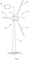
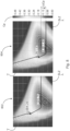
- Fig. 1 shows a wind turbine 100 with a tower 102 and a nacelle 104.
- a rotor 106 with three rotor blades 108 and a spinner is arranged on the nacelle 104.
- the rotor 106 is caused to rotate by the wind and thereby drives a generator in the nacelle 104.
- the rotor blades 108 are adjustable in their blade angle.
- the blade pitch angles ⁇ of the rotor blades 108 can be determined by the rotor blade roots 114 (cf. Fig. 2 ) of the respective rotor blades 108 arranged pitch motors can be changed.
- the rotor 106 is operated with a nominal rotor speed n that can be set depending on the operating mode.
- the wind turbine 100 is controlled by a controller 200, which is part of a comprehensive controller of the wind turbine 100.
- the controller 200 is generally implemented as part of the controller of the wind turbine 100.
- the wind turbine 100 can be operated in a power-optimized operating mode or a noise-reduced operating mode by means of the control 200.
- the power-optimized operating mode the wind turbine 100 generates the optimum with the Wind turbine 100 generates power.
- the reduced-noise operating mode the wind turbine 100 is operated at a reduced nominal rotor speed compared to the power-optimized operating mode in order to set a sound power level that is less than or equal to a sound power level specified by sound power level requirements.
- wind turbines 100 can be part of a wind farm. Depending on their location, the wind turbines 100 are subject to a wide range of environmental and framework conditions. In particular, the sound power level requirements for the wind turbine can vary depending on the location. Furthermore, the properties of the wind field to which the wind turbines are exposed during the day and season can vary greatly. The wind field is characterized by a large number of parameters. The most important wind field parameters are average wind speed, turbulence, vertical and horizontal shear, wind direction change over height, oblique flow and air density.
- one measure for operating a wind turbine provides for counteracting the increase in the angle of attack on the rotor blade caused by the reduced nominal rotor speed in noise-reduced operation by increasing the blade setting angle ⁇ , also referred to as the pitch angle, from a certain power onwards in order to avoid an impending flow separation in the central region of the rotor blade 108, which would lead to severe power losses.
- This increase in the blade setting angle ⁇ leads to power losses of the wind turbine 100, which are generally lower than the power losses that would result from the flow separation occurring on the respective rotor blades 108.
- a design of the occupancy of vortex generators 118 on the rotor blade 108 adapted to a location with a lower sound power level to be set as in Fig. 2 shown as an example.
- the vortex generators 118 which are mounted over an extended area in the middle section of the rotor blade 108 depending on the sound power level to be set at a location of the wind turbine 100, prevent flow separation in the middle section and as a result it is possible to reduce the increase in the blade pitch angle ⁇ or to set a lower blade pitch angle, which in total can lead to a higher yield of the wind turbine 100.
- Fig.2 shows a schematic view of a single rotor blade 108 with a rotor blade leading edge 110 and a rotor blade trailing edge 112.
- the rotor blade 108 has a Rotor blade root 114 and a rotor blade tip 116.
- the distance between the rotor blade root 114 and the rotor blade tip 116 is referred to as the outer radius R of the rotor blade 108.
- the distance between the rotor blade leading edge 110 and the rotor blade trailing edge 112 is referred to as the profile depth T.
- the rotor blade 108 At the rotor blade root 114 or generally in the area near the rotor blade root 114, the rotor blade 108 has a large profile depth T.
- the profile depth T is much smaller. Starting from the rotor blade root 114, in this example after an increase in the inner area of the blade, the profile depth T decreases significantly up to a middle area. A separation point can be provided in the middle area (not shown here). From the middle area to the rotor blade tip 116, the profile depth T is almost constant, or the decrease in the profile depth T is significantly reduced.
- Vortex generators 118 which can be designed as vortex generators, for example, are arranged on the suction side. Alternative designs of the vortex generators 118 as active or passive elements for influencing the flow are conceivable. While the vortex generators 118 are shown arranged on the suction side of the rotor blade 108 in the example shown, alternatively or additionally vortex generators 118 are possible on the pressure side of the rotor blade 108 in the arrangement according to the invention.
- the vortex generators 118 can be arranged in the area of the rotor blade leading edge 110 or at another position between the rotor blade leading edge 110 and the rotor blade trailing edge 112. The extent of the arrangement of the vortex generators 118 begins in the area of the rotor blade root 114 and runs in the direction of the rotor blade tip 116.
- the vortex generators 118 extend in the radial direction to a position P A or P B on the rotor blade 108.
- the respective position P A or P B on the rotor blade 108 is specified as a radius position in relation to a standardized radius r/R.
- the radius position in relation to the standardized radius r/R represents the position on the rotor blade 108 along the rotor blade longitudinal axis as the radius r a , r b of the respective position P A , P B in relation to the outer radius R of the rotor 108 or the rotor blade length.
- the respective position P A or P B on the rotor blade 108 can therefore be specified as a radius position r/R with a value in the range from 0 (zero) to 1 (one).
- the vortex generators 118 are arranged in the longitudinal direction of the rotor blade 108 up to a radius position r/R depending on the location-specific sound power level to be set.
- the arrangement of the vortex generators 118 starting from the rotor blade root 114 in the direction of the rotor blade tip 116 up to the radius position r/R of the rotor blade 108 is carried out in such a way that in the noise-reduced operating mode with the nominal rotor speed reduced compared to the power-optimized operating mode and a setting of the blade pitch angle ⁇ of the rotor blade 108 adapted to the arrangement of the vortex generators 118, a flow separation to be expected due to the reduced nominal rotor speed is prevented and an expected power loss is minimized.
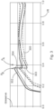
- Fig.3 shows, for two exemplary, different operating situations (case A and case B), which are listed in the table below, exemplary different courses 302, 303 (case B) and 304, 305 (case A) of an angle of attack reserve ⁇ reserve on the rotor blade 108 over the radius position r/R.
- the operating situations case A and case B differ from one another with regard to the radius position r A , r B up to which the rotor blade 108 is occupied by vortex generators 118 or the position P A , P B of the occupation of the rotor blade 108 with vortex generators 118 as well as a blade pitch angle characteristic curve 602 (case B) and 604 (case A) selected for operation (cf. Fig.6 ).
- the end point of the coverage with vortex generators 118 in the longitudinal direction of the rotor blade 108 is indicated by a sudden drop in the angle of attack reserve in the graph of the Fig.3 visible.
- the angle of attack reserve depends on the wind speed, the curves 302, 304 are shown for an exemplary wind speed of 6 m/s, whereas the curves 303, 305 show the curves for the wind speed at which the lowest angle of attack reserve is present.
- the wind speeds on which the curves 303 and 305 are based do not have to be and in practice will most likely not be identical, since the arrangement of the vortex generators 118 has a significant influence on the wind speed dependence of the angle of attack reserve.
- the wind turbine 100 is subject to the same sound power level requirements, so that in both case B and case A, the operating parameters of the wind turbine 100, in particular nominal rotor speeds in the noise-reduced operating mode, blade pitch angle of the rotor blades and radius position up to which the rotor blade 108 is occupied by vortex generators 118, are selected such that it emits a sound power level to be set that is equal to or less than a sound power level according to the sound power level requirements.
- Table of operating situations Case B Vortex generators up to r B , blade pitch characteristic P B
- Case A Vortex generators up to r A blade pitch characteristic P A
- the vortex generators are arranged up to the position P B and the wind turbine is operated with the blade pitch angle characteristic 602.
- the combination of assignment with vortex generators and blade pitch angle ⁇ makes it possible to maintain a sufficient angle of attack reserve over the entire length of the rotor blade and thus avoid flow stalls.
- Case A describes the case according to which by changing the position at which the vortex generators end, namely at position P A, safe operation with the preferred blade pitch angle characteristic curve 604 is possible without flow stalls occurring.
- the blade pitch angles ⁇ of the blade pitch angle characteristic curve 604 are lower in comparison with the blade pitch angles ⁇ of the blade pitch angle characteristic curve 602 (cf. Fig. 6 ). This makes it possible to generate greater power (cf. Fig. 5 ) and thus a higher overall annual energy yield (cf. Fig. 7 ) to obtain.
- the wind turbine in case A can be operated with a higher power coefficient than in case B (cf. Fig. 8 ).
- a method for designing and operating a wind turbine for example the wind turbine 100 from Fig.1 with rotor blades 108, which are equipped with vortex generators 118, as shown in Fig.2 shown, for generating electrical power from wind.
- a radius position r/R up to which the occupancy of the vortex generators 118 is carried out in the longitudinal direction of the respective rotor blade 108 is determined depending on a sound power level to be set at a location of the wind turbine 100.
- the blade pitch angle ⁇ of the rotor blades 108 with which the wind turbine 100 is operated can be determined depending on the sound power level to be set at the location of the wind turbine 100.
- the wind turbine 100 can be operated with a nominal rotor speed that is reduced compared to the power-optimized operating mode depending on the sound power level to be set at the location of the wind turbine 100.
- the determination of the radius position r/R at which the vortex generators 118 end and the blade pitch angle ⁇ of the rotor blades 108 with which the wind turbine 100 is operated This can also be done depending on the sound power level to be set in such a way that flow separation, which is expected due to the reduced nominal rotor speed, is prevented and any expected power loss is minimized.
- the assignment of the vortex generators 118 in the longitudinal direction of the respective rotor blade 108 can be carried out up to the radius position r/R, which is determined depending on the reduced nominal rotor speed.
- the determination of the radius position r/R up to which the occupancy of the vortex generators 118 is carried out in the longitudinal direction of the respective rotor blade 108 can also be carried out depending on the sound power level to be set in such a way that an increase in the blade pitch angle ⁇ , which is necessary at a lower sound power level to be set, is achieved by a necessary reduction the nominal rotor speed is minimized.
- the determination of the radius position r/R at which the vortex generators 118 end and the blade setting angle ⁇ of the rotor blades 108 with which the wind turbine 100 is operated can be carried out depending on the sound power level to be set in such a way that in a hybrid operation including operating periods in the performance-optimized operating mode and in noise-reduced operating mode, yield losses in the performance-optimized operating mode can at least be compensated for by yield gains in the noise-reduced operating mode over a certain period of time.
- the adjustment of the blade pitch angle ⁇ can be carried out depending on the radius position r/R determined for the occupancy of the vortex generators 118.
- the rotor blades 108 can be equipped with the vortex generators 118 taking into account a specific operating management, in particular a specific nominal power with which the wind turbine 100 is operated at a location.
- a specific operating management in particular a specific nominal power with which the wind turbine 100 is operated at a location.
- the nominal power in hybrid operation or the reduced nominal power in the noise-reduced operating mode can be taken into account.
- blade pitch characteristics can be stored, for example in the control system 200.
- a blade pitch characteristic can be selected from the stored blade pitch characteristics depending on the radius position r/R determined for the occupancy of the vortex generators 118 and used to set the blade pitch angle ⁇ .
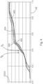
- Example curves 402, 403 and 404, 405 of the glide ratio are shown for the two different operating situations, case B and case A.
- the curves 402, 403 arise for case B.
- the courses 404, 405 arise for case A, with the respective courses as in Fig. 3 different wind speeds.
- the curves 402, 404 are shown for an exemplary wind speed of 6 m/s, whereas the curves 403, 405 show the curves for the wind speed at which the lowest angle of attack reserve is present.
- the course 404 of the glide ratio in case A is qualitatively essentially similar to the course 402 up to the radius position r/R of approximately 0.37. However, from the radius position r/R of approximately 0.39, the glide ratio is always higher than for course 402.
- the blade pitch angle Y is increased.
- a blade pitch angle ⁇ that is characteristic for the use of vortex generators i.e. a blade pitch angle characteristic curve 602 or 604, is selected.
- the increase in the blade pitch angle leads to a reduction in the angle of attack ⁇ on the rotor blade 108 over the entire rotor radius R, so that it is ensured that the angle of attack ⁇ is in a permissible range and that flow separation does not occur.
- the blade pitch angle preferably extends from 0° to 90° from a rotor plane to a wind direction assumed to be perpendicular to the rotor plane.
- An increase in the pitch angle or blade pitch angle therefore leads to the profile chord of the rotor blade twisting towards the wind direction. Accordingly, an increase in the blade pitch angle leads to a reduction in the angle of attack.
- the largest increases in the angle of attack when operating the wind turbine 100 occur in the middle part of the rotor blade 108. This is particularly the case at radius positions that adjoin the position P B of already attached vortex generators 118 in the radial direction. In order to counteract this, it is planned to extend the occupancy of the rotor blades 108 by vortex generators 118 beyond the position P B radially to a position P A during noise-reduced operation of the wind turbine 100 at locations with a lower sound power level to be set. This counteracts the risk of flow separation in the middle part of the rotor blade, in particular between position P B and position P A.
- Fig. 5 shows examples of different performance curves 502 and 504 for the operating situations case B and case A.
- the performance curve 502 arises in case B and the performance curve 504 arises in case A.
- case A compared to case B, a higher wind speed v can be achieved for a certain area in the partial load range according to the power curves 504 and 502 achieve power consumption.
- This increased power consumption in case A leads to the yield gains through which the increased resistance in the area of additional occupancy by vortex generators 118 beyond the position P B up to the position P A can be compensated or overcompensated.
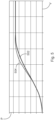
- FIG.6 Two blade pitch angle characteristic curves 602 and 604 are shown as examples for the two different operating situations.
- the blade pitch angle characteristic curve 602 is used as the basis for the operating situation in case B of the control of the blade pitch angle ⁇ .
- the blade pitch angle characteristic curve 604 is used as the basis for the operating situation in case A of the control of the blade pitch angle Y by the control 200.
- the blade pitch angle ⁇ for case A is always smaller than the blade pitch angle ⁇ for case B.
- the minimum blade pitch angle ⁇ Amin is smaller than the minimum blade pitch angle yamin.
- the exemplary blade pitch angle characteristics 602, 604 are defined as characteristics defined in sections with, in this example, three linear sections. Up to a first power threshold value P Amin1 or P Bmin1, the blade pitch angle remains at the respective minimum blade pitch angle ⁇ Amin or ⁇ Bmin found for the blade pitch angle characteristics 602, 604. From this first power threshold value P Amin1 or P Bmin1 , there is a blade pitch angle increase ⁇ Amin1 or ⁇ Bmin1 that is linear with the power until a second power threshold value P Amin2 or P Bmin2 is reached. From this second power threshold value P Amin2 or P Bmin2 , there is then a blade pitch angle increase ⁇ Amin2 or ⁇ Bmin2 that is also linear with the power until the nominal power is reached. The blade angle increase ⁇ A,Bmin2 can be greater, smaller or equal to the blade angle increase ⁇ A,Bmin1 .
- the blade pitch angle characteristic curve can be particularly successfully defined for this purpose by the minimum blade pitch angle ⁇ min , a power threshold value from which an increase in the blade pitch angle begins, and two subsequent linear ranges, each with a constant blade pitch angle increase.
- ⁇ min a power threshold value from which an increase in the blade pitch angle begins
- two subsequent linear ranges each with a constant blade pitch angle increase.
- other functions for the blade pitch angle can also be used, for example simpler functions with only a single linear range of the blade pitch angle increase, or more complicated ones that are not just linear first-order functions of the power, for example.
- the approach found offers a particularly suitable compromise for practical use between the complexity of both the optimization process and the implementation in the control of the wind turbine and, at the same time, the best possible energy yield, i.e. the lowest possible deviation from an ideal blade pitch angle characteristic curve.
- Another aspect takes into account the fact that when operating a type of wind turbine, location- and operating mode-dependent nominal power P nominal is offered.
- the adjustment of the nominal power P Nenn can be realized by adjusting the nominal rotor speed.
- Higher nominal rotor speeds lead to higher speed speeds in the range of the nominal power P nominal and thus to reduced angles of attack ⁇ for the same power. As a result, the risk of flow separation is reduced.
- higher rated rotor speeds result in higher sound power levels, so when adjusting the rated rotor speed in the event that sound power level requirements need to be met at the site, the rated rotor speed must be adjusted accordingly.
- Fig.7 shows annual energy yields AEP represented by bars 702 (case B) and 704 (case A) as a function of different average wind speeds vd.
- the annual energy yield AEP for all average wind speeds vd is always higher than in case B.
- the combination of equipping the rotor blade 108 with vortex generators 118 up to position P A and setting the blade pitch angle ⁇ according to the blade pitch angle characteristic curve 604 thus makes it possible to achieve a higher annual energy yield compared to a location-independent equipping of the rotor blade 108 with vortex generators 118 up to position P B and setting the blade pitch angle ⁇ according to the blade pitch angle characteristic curve 602, if sound power level requirements are to be met.
- Fig. 8 shows rotor maps 802 (case B) and 804 (case A) of the power coefficient as a function of the blade pitch angle ⁇ and the high-speed speed number SLZ.
- case A the wind turbine 100 can be operated with a higher power coefficient Cp.
- case B a performance coefficient ⁇ Cp higher can be achieved.
- Fig. 9 shows an example of annual energy yield differences ⁇ AEP in a hybrid operation of a wind turbine depending on the ABM shares of a performance-optimized operating mode and a noise-reduced operating mode for different operating situations.
- the proportion of noise-reduced operating mode is between 0% and 100%.
- a curve 900 is shown, which shows the annual energy yield for a wind turbine with a known occupancy of vortex generators and known operational management.
- the other curves 910, 912, 914, 920, 922, 924 show the annual energy yield differences ⁇ AEP relative to the curve 900, whereby in the Fig.9 above the course 900 Trends below 900 mean an increase in yield and trends below 900 mean a decrease in yield.
- the curves 900, 910 and 920 represent cases in which the radius position r/R at which the occupancy of the rotor blade with vortex generators ends gradually increases, i.e. the radius position r/R at which the occupancy of the rotor blade with vortex generators ends is for the curve 920 larger than for course 910 and for course 910 larger than for course 900.
- the operational management of the wind turbines identical It can be seen that the annual energy production decreases regardless of the proportion of ABM, i.e. extending the occupancy of the rotor blade towards the tip of the rotor blade while otherwise maintaining operational management results in a deterioration in the AEP.
- the curves 912 and 922 have, for example, a common first power threshold value, from which pitching takes place at a constant blade pitch angle rate.
- the curves 914 and 924 in turn have an adapted operating management, for example a changed, e.g. higher, first power threshold value and a changed blade pitch angle rate.
- the minimum blade setting angles between the operating guides on which the courses 912 and 922 or 914 and 924 are based can also be different.
Claims (13)
- Procédé de conception et de fonctionnement d'une éolienne (100) pour la production d'énergie électrique à partir du vent, dans lequel l'éolienne (100) présente un rotor (106) aérodynamique avec des pales de rotor (108) réglables dans leur angle de réglage de pale (γ), dans lequel les pales de rotor (108) sont garnies, dans des positions de rayon dans le sens longitudinal entre l'emplanture de pale de rotor (114) et la pointe de pale de rotor (116), par plusieurs générateurs de tourbillon (118), caractérisé en ce qu'une position de rayon (r/R), jusqu'à laquelle la garniture des générateurs de tourbillon (118) est réalisée dans le sens longitudinal de la pale de rotor (108) respective à partir de l'emplanture de pale de rotor en direction de la pointe de pale de rotor, est déterminée en fonction d'un niveau de puissance sonore à régler à un endroit de l'éolienne (100) de sorte que l'éolienne satisfasse aux exigences du niveau de puissance sonore à l'endroit de l'éolienne.
- Procédé selon la revendication 1, caractérisé en ce qu'en outre l'angle de réglage de pale (γ) des pales de rotor (108), avec lequel l'éolienne (100) fonctionne, est déterminé en fonction du niveau de puissance sonore à régler à l'endroit de l'éolienne (100).
- Procédé selon la revendication 2, caractérisé en ce que l'éolienne (100) fonctionne dans un mode de fonctionnement à bruit réduit en fonction du niveau de puissance sonore à régler à l'endroit de l'éolienne (100) avec une vitesse de rotation de rotor nominale réduite par rapport à un mode de fonctionnement optimisé en puissance.
- Procédé selon la revendication 3, caractérisé en ce que la détermination de la position de rayon (r/R), dans laquelle se terminent les générateurs de tourbillon (118) et de l'angle de réglage de pale (γ) des pales de rotor (108), avec lesquelles l'éolienne (100) fonctionne, est effectuée en fonction du niveau de puissance sonore à régler de telle manière qu'une interruption d'écoulement à attendre en raison de la vitesse de rotation de rotor nominale réduite soit empêchée et une perte de puissance à attendre soit minimisée.
- Procédé selon la revendication 3 ou 4, caractérisé en ce que la garniture des générateurs de tourbillon (118) est réalisée dans le sens longitudinal de la pale de rotor (108) respective jusqu'à une position de rayon (r/R) qui est déterminée en fonction de la vitesse de rotation de rotor nominale réduite.
- Procédé selon l'une quelconque des revendications 3 à 5, caractérisé en ce que la détermination de la position de rayon (r/R), jusqu'à laquelle la garniture des générateurs de tourbillon (118) est réalisée dans le sens longitudinal de la pale de rotor (108) respective, est effectuée en fonction du niveau de puissance sonore à régler de telle manière qu'une augmentation nécessaire, en cas de niveau de puissance sonore à régler plus bas, de l'angle de réglage de pale (γ), qui est conditionnée par une réduction nécessaire de la vitesse de rotation de rotor nominale, soit minimisée.
- Procédé selon l'une quelconque des revendications 3 à 6, caractérisé en ce que la détermination de la position de rayon (r/R), dans laquelle les générateurs de tourbillon (118) se terminent, et de l'angle de réglage de pale (γ) des pales de rotor (108), avec lequel l'éolienne (100) fonctionne, est effectuée en fonction du niveau de puissance sonore à régler de telle manière que, dans un mode hybride contenant des périodes de fonctionnement en mode de fonctionnement optimisé en puissance et dans en mode de fonctionnement à bruit réduit, des pertes de rendement en mode de fonctionnement optimisé en puissance sont au moins compensées par des gains de rendement en mode de fonctionnement à bruit réduit sur une période déterminée.
- Procédé selon l'une quelconque des revendications précédentes, caractérisé en ce que le réglage de l'angle de réglage de pale (γ) est réalisé en fonction de la position de rayon (r/R) déterminée pour la garniture des générateurs de tourbillon (118).
- Procédé selon l'une quelconque des revendications précédentes, caractérisé en ce que la garniture de la pale de rotor (108) avec les générateurs de tourbillon (118) est réalisée en tenant compte d'une exploitation spécifique, en particulier d'une puissance nominale spécifique, avec laquelle l'éolienne (100) fonctionne à un endroit.
- Procédé selon l'une quelconque des revendications précédentes, caractérisé en ce que plusieurs lignes caractéristiques de réglage de pale (602, 604) sont enregistrées et une ligne caractéristique de réglage de pale (604) est sélectionnée parmi les lignes caractéristiques de réglage de pale (602, 604) enregistrées en fonction de la position de rayon (r/R) déterminée pour la garniture des générateurs de tourbillon (118) et est utilisée pour le réglage de l'angle de réglage de pale (γ).
- Procédé selon l'une quelconque des revendications précédentes, dans lequel la position de rayon (r/R), jusqu'à laquelle la garniture des générateurs de tourbillon (118) est réalisée dans le sens longitudinal de la pale de rotor (108) respective, est déterminée en fonction d'une part d'un mode de fonctionnement à bruit réduit à l'endroit de l'éolienne (100).
- Procédé selon la revendication 11, dans lequel, en outre, une exploitation de l'éolienne, en particulier un réglage de l'angle de réglage de pale (γ), est déterminée en fonction de la part du mode de fonctionnement à bruit réduit à l'endroit de l'éolienne (100).
- Eolienne (100) comprenant un rotor (106) aérodynamique avec des pales de rotor (108) réglables dans leur angle de réglage de pale (γ), dans laquelle le rotor (106) peut fonctionner dans un mode de fonctionnement respectif avec une vitesse de rotation de rotor nominale réglable respective, ainsi qu'une régulation (200), caractérisée en ce que la régulation (200) est conçue afin de faire fonctionner l'éolienne (100) selon un procédé selon au moins l'une quelconque des revendications 1 à 12.
Applications Claiming Priority (1)
| Application Number | Priority Date | Filing Date | Title |
|---|---|---|---|
| DE102020113261 | 2020-05-15 |
Publications (3)
| Publication Number | Publication Date |
|---|---|
| EP3916218A1 EP3916218A1 (fr) | 2021-12-01 |
| EP3916218C0 EP3916218C0 (fr) | 2024-04-03 |
| EP3916218B1 true EP3916218B1 (fr) | 2024-04-03 |
Family
ID=75914358
Family Applications (1)
| Application Number | Title | Priority Date | Filing Date |
|---|---|---|---|
| EP21173501.4A Active EP3916218B1 (fr) | 2020-05-15 | 2021-05-12 | Procédé de conception et de fonctionnement d'une éolienne, éolienne, ainsi que parc éolien |
Country Status (3)
| Country | Link |
|---|---|
| US (1) | US11668281B2 (fr) |
| EP (1) | EP3916218B1 (fr) |
| CN (1) | CN113669193A (fr) |
Families Citing this family (2)
| Publication number | Priority date | Publication date | Assignee | Title |
|---|---|---|---|---|
| DE102018100727A1 (de) * | 2018-01-15 | 2019-07-18 | Wobben Properties Gmbh | Verfahren zum Steuern einer Windenergieanlage und Windenergieanlage |
| EP3875752A1 (fr) * | 2020-03-05 | 2021-09-08 | Siemens Gamesa Renewable Energy A/S | Procédé et dispositif pour commander une éolienne pour réduire le bruit |
Family Cites Families (12)
| Publication number | Priority date | Publication date | Assignee | Title |
|---|---|---|---|---|
| EP3617496A1 (fr) * | 2006-04-02 | 2020-03-04 | Wobben Properties GmbH | Éolienne à pales effilées |
| EP2027390B2 (fr) | 2006-06-09 | 2020-07-01 | Vestas Wind Systems A/S | Pale d'éolienne et éolienne à régulation de pas |
| EP2129908B1 (fr) * | 2007-03-20 | 2010-12-01 | Vestas Wind Systems A/S | Pales d'éolienne à générateurs de vortex |
| US8038396B2 (en) * | 2010-06-22 | 2011-10-18 | General Electric Company | Vortex generator assembly for use with a wind turbine rotor blade and method for assembling a wind turbine rotor blade |
| CN104364517B (zh) * | 2012-03-13 | 2017-10-24 | 柯尔顿控股有限公司 | 扭转的叶片根部 |
| EP2713044B2 (fr) | 2012-09-28 | 2022-12-07 | Siemens Gamesa Renewable Energy A/S | Pale de rotor d'éolienne |
| DE102013202881A1 (de) | 2013-02-21 | 2014-08-21 | Wobben Properties Gmbh | Rotorblatthinterkante |
| EP3084209B1 (fr) * | 2013-12-20 | 2019-09-25 | LM WP Patent Holding A/S | Pale d'éolienne à dispositifs aérodynamiques déployables |
| US9422915B2 (en) | 2014-05-08 | 2016-08-23 | Siemens Aktiengesellschaft | Customizing a wind turbine for site-specific conditions |
| DE102015008813A1 (de) | 2015-07-10 | 2017-01-12 | Senvion Gmbh | Vortexgenerator |
| US10400744B2 (en) | 2016-04-28 | 2019-09-03 | General Electric Company | Wind turbine blade with noise reducing micro boundary layer energizers |
| DE102018127804A1 (de) | 2018-11-07 | 2020-05-07 | fos4X GmbH | Verbesserung bzw. Optimierung des Ertrags einer Windenergieanlage durch Detektion eines Strömungsabrisses |
-
2021
- 2021-05-12 EP EP21173501.4A patent/EP3916218B1/fr active Active
- 2021-05-12 US US17/318,392 patent/US11668281B2/en active Active
- 2021-05-14 CN CN202110527837.1A patent/CN113669193A/zh active Pending
Also Published As
| Publication number | Publication date |
|---|---|
| EP3916218C0 (fr) | 2024-04-03 |
| US20210355912A1 (en) | 2021-11-18 |
| CN113669193A (zh) | 2021-11-19 |
| US11668281B2 (en) | 2023-06-06 |
| EP3916218A1 (fr) | 2021-12-01 |
Similar Documents
| Publication | Publication Date | Title |
|---|---|---|
| EP1514023B1 (fr) | Eolienne | |
| EP3916218B1 (fr) | Procédé de conception et de fonctionnement d'une éolienne, éolienne, ainsi que parc éolien | |
| EP2339171B1 (fr) | Pale pour une éolienne | |
| DE102011051831B4 (de) | Rotorblatt für eine Windkraftanlage mit einem Saugseitenwinglet | |
| WO2020064925A1 (fr) | Procédé pour faire fonctionner une éolienne, éolienne et parc éolien | |
| EP2280163B1 (fr) | Eolienne et pale de rotor d'une eolienne | |
| EP3443223B1 (fr) | Procédé pour faire fonctionner une éolienne | |
| EP3755899B1 (fr) | Pale de rotor d'une installation éolienne comprenant une plaque de déviation de la couche limite | |
| DE102012013896A1 (de) | Windenergieanlage | |
| EP3701143B1 (fr) | Pale de rotor d'une éolienne et procédé de conception de celle-ci | |
| WO2019234168A1 (fr) | Procédé pour faire fonctionner une éolienne | |
| EP3399183B1 (fr) | Pale de rotor d'une éolienne | |
| WO2019030205A1 (fr) | Pale de rotor d'un rotor d'un aérogénérateur, aérogénérateur et procédé d'amélioration du taux de rendement d'un rotor d'un aérogénérateur | |
| EP3969742A1 (fr) | Procédé pour déposer et pour faire fonctionner une éolienne, éolienne et parc éolien | |
| WO2021008972A1 (fr) | Pale de rotor et éolienne | |
| DE102010026244A1 (de) | Verfahren zur Berücksichtigung von Nachlaufeffekten bei Windturbinen | |
| EP3824176A1 (fr) | Pale de rotor pour éolienne et éolienne | |
| EP3842633B1 (fr) | Procédé de fonctionnement d'une éolienne, éolienne et parc éolien | |
| EP3981981A1 (fr) | Pale de rotor pour une éolienne, éolienne et procédé de conception d'une pale de rotor | |
| EP3995691A1 (fr) | Procédé de fonctionnement d'une éolienne, éolienne et parc éolien | |
| EP3499023A1 (fr) | Procédé et système de fonctionnement d'une éolienne | |
| EP4227522A1 (fr) | Pale de rotor, éolienne, angle de dentelure, paramètre environnemental | |
| EP3969741B1 (fr) | Pale de rotor et éolienne | |
| EP3768970B1 (fr) | Procédé pour faire fonctionner une éolienne, éolienne et parc éolien | |
| EP4306796A1 (fr) | Procédé permettant d'influencer l'émission sonore d'une pale de rotor d'éolienne |
Legal Events
| Date | Code | Title | Description |
|---|---|---|---|
| PUAI | Public reference made under article 153(3) epc to a published international application that has entered the european phase |
Free format text: ORIGINAL CODE: 0009012 |
|
| STAA | Information on the status of an ep patent application or granted ep patent |
Free format text: STATUS: THE APPLICATION HAS BEEN PUBLISHED |
|
| AK | Designated contracting states |
Kind code of ref document: A1 Designated state(s): AL AT BE BG CH CY CZ DE DK EE ES FI FR GB GR HR HU IE IS IT LI LT LU LV MC MK MT NL NO PL PT RO RS SE SI SK SM TR |
|
| B565 | Issuance of search results under rule 164(2) epc |
Effective date: 20211028 |
|
| STAA | Information on the status of an ep patent application or granted ep patent |
Free format text: STATUS: REQUEST FOR EXAMINATION WAS MADE |
|
| 17P | Request for examination filed |
Effective date: 20220601 |
|
| RBV | Designated contracting states (corrected) |
Designated state(s): AL AT BE BG CH CY CZ DE DK EE ES FI FR GB GR HR HU IE IS IT LI LT LU LV MC MK MT NL NO PL PT RO RS SE SI SK SM TR |
|
| GRAP | Despatch of communication of intention to grant a patent |
Free format text: ORIGINAL CODE: EPIDOSNIGR1 |
|
| STAA | Information on the status of an ep patent application or granted ep patent |
Free format text: STATUS: GRANT OF PATENT IS INTENDED |
|
| INTG | Intention to grant announced |
Effective date: 20231117 |
|
| GRAS | Grant fee paid |
Free format text: ORIGINAL CODE: EPIDOSNIGR3 |
|
| GRAA | (expected) grant |
Free format text: ORIGINAL CODE: 0009210 |
|
| STAA | Information on the status of an ep patent application or granted ep patent |
Free format text: STATUS: THE PATENT HAS BEEN GRANTED |
|
| AK | Designated contracting states |
Kind code of ref document: B1 Designated state(s): AL AT BE BG CH CY CZ DE DK EE ES FI FR GB GR HR HU IE IS IT LI LT LU LV MC MK MT NL NO PL PT RO RS SE SI SK SM TR |
|
| REG | Reference to a national code |
Ref country code: CH Ref legal event code: EP |
|
| REG | Reference to a national code |
Ref country code: DE Ref legal event code: R096 Ref document number: 502021003161 Country of ref document: DE |
|
| U01 | Request for unitary effect filed |
Effective date: 20240404 |