EP3916145B1 - Türverriegelungsvorrichtung mit verbessertem sicherheitsmodul - Google Patents
Türverriegelungsvorrichtung mit verbessertem sicherheitsmodul Download PDFInfo
- Publication number
- EP3916145B1 EP3916145B1 EP21172037.0A EP21172037A EP3916145B1 EP 3916145 B1 EP3916145 B1 EP 3916145B1 EP 21172037 A EP21172037 A EP 21172037A EP 3916145 B1 EP3916145 B1 EP 3916145B1
- Authority
- EP
- European Patent Office
- Prior art keywords
- slider
- door
- pin
- safety
- locking pin
- Prior art date
- Legal status (The legal status is an assumption and is not a legal conclusion. Google has not performed a legal analysis and makes no representation as to the accuracy of the status listed.)
- Active
Links
Images


Classifications
-
- E—FIXED CONSTRUCTIONS
- E05—LOCKS; KEYS; WINDOW OR DOOR FITTINGS; SAFES
- E05B—LOCKS; ACCESSORIES THEREFOR; HANDCUFFS
- E05B47/00—Operating or controlling locks or other fastening devices by electric or magnetic means
- E05B47/06—Controlling mechanically-operated bolts by electro-magnetically-operated detents
- E05B47/0603—Controlling mechanically-operated bolts by electro-magnetically-operated detents the detent moving rectilinearly
-
- E—FIXED CONSTRUCTIONS
- E05—LOCKS; KEYS; WINDOW OR DOOR FITTINGS; SAFES
- E05B—LOCKS; ACCESSORIES THEREFOR; HANDCUFFS
- E05B65/00—Locks or fastenings for special use
-
- A—HUMAN NECESSITIES
- A47—FURNITURE; DOMESTIC ARTICLES OR APPLIANCES; COFFEE MILLS; SPICE MILLS; SUCTION CLEANERS IN GENERAL
- A47L—DOMESTIC WASHING OR CLEANING; SUCTION CLEANERS IN GENERAL
- A47L15/00—Washing or rinsing machines for crockery or tableware
- A47L15/42—Details
- A47L15/4251—Details of the casing
- A47L15/4257—Details of the loading door
- A47L15/4259—Arrangements of locking or security/safety devices for doors, e.g. door latches, switch to stop operation when door is open
-
- D—TEXTILES; PAPER
- D06—TREATMENT OF TEXTILES OR THE LIKE; LAUNDERING; FLEXIBLE MATERIALS NOT OTHERWISE PROVIDED FOR
- D06F—LAUNDERING, DRYING, IRONING, PRESSING OR FOLDING TEXTILE ARTICLES
- D06F37/00—Details specific to washing machines covered by groups D06F21/00 - D06F25/00
- D06F37/26—Casings; Tubs
- D06F37/28—Doors; Security means therefor
-
- D—TEXTILES; PAPER
- D06—TREATMENT OF TEXTILES OR THE LIKE; LAUNDERING; FLEXIBLE MATERIALS NOT OTHERWISE PROVIDED FOR
- D06F—LAUNDERING, DRYING, IRONING, PRESSING OR FOLDING TEXTILE ARTICLES
- D06F37/00—Details specific to washing machines covered by groups D06F21/00 - D06F25/00
- D06F37/42—Safety arrangements, e.g. for stopping rotation of the receptacle upon opening of the casing door
-
- D—TEXTILES; PAPER
- D06—TREATMENT OF TEXTILES OR THE LIKE; LAUNDERING; FLEXIBLE MATERIALS NOT OTHERWISE PROVIDED FOR
- D06F—LAUNDERING, DRYING, IRONING, PRESSING OR FOLDING TEXTILE ARTICLES
- D06F39/00—Details of washing machines not specific to a single type of machines covered by groups D06F9/00 - D06F27/00
- D06F39/12—Casings; Tubs
- D06F39/14—Doors or covers; Securing means therefor
-
- E—FIXED CONSTRUCTIONS
- E05—LOCKS; KEYS; WINDOW OR DOOR FITTINGS; SAFES
- E05C—BOLTS OR FASTENING DEVICES FOR WINGS, SPECIALLY FOR DOORS OR WINDOWS
- E05C19/00—Other devices specially designed for securing wings, e.g. with suction cups
- E05C19/02—Automatic catches, i.e. released by pull or pressure on the wing
-
- E—FIXED CONSTRUCTIONS
- E05—LOCKS; KEYS; WINDOW OR DOOR FITTINGS; SAFES
- E05B—LOCKS; ACCESSORIES THEREFOR; HANDCUFFS
- E05B47/00—Operating or controlling locks or other fastening devices by electric or magnetic means
- E05B2047/0048—Circuits, feeding, monitoring
- E05B2047/0067—Monitoring
- E05B2047/0068—Door closed
-
- E—FIXED CONSTRUCTIONS
- E05—LOCKS; KEYS; WINDOW OR DOOR FITTINGS; SAFES
- E05B—LOCKS; ACCESSORIES THEREFOR; HANDCUFFS
- E05B63/00—Locks or fastenings with special structural characteristics
- E05B2063/0026—Elongated, e.g. stud-like, striker entering into an opening in which movable detent means engage the elongated striker
-
- E—FIXED CONSTRUCTIONS
- E05—LOCKS; KEYS; WINDOW OR DOOR FITTINGS; SAFES
- E05Y—INDEXING SCHEME ASSOCIATED WITH SUBCLASSES E05D AND E05F, RELATING TO CONSTRUCTION ELEMENTS, ELECTRIC CONTROL, POWER SUPPLY, POWER SIGNAL OR TRANSMISSION, USER INTERFACES, MOUNTING OR COUPLING, DETAILS, ACCESSORIES, AUXILIARY OPERATIONS NOT OTHERWISE PROVIDED FOR, APPLICATION THEREOF
- E05Y2900/00—Application of doors, windows, wings or fittings thereof
- E05Y2900/30—Application of doors, windows, wings or fittings thereof for domestic appliances
- E05Y2900/304—Application of doors, windows, wings or fittings thereof for domestic appliances for dishwashers
-
- E—FIXED CONSTRUCTIONS
- E05—LOCKS; KEYS; WINDOW OR DOOR FITTINGS; SAFES
- E05Y—INDEXING SCHEME ASSOCIATED WITH SUBCLASSES E05D AND E05F, RELATING TO CONSTRUCTION ELEMENTS, ELECTRIC CONTROL, POWER SUPPLY, POWER SIGNAL OR TRANSMISSION, USER INTERFACES, MOUNTING OR COUPLING, DETAILS, ACCESSORIES, AUXILIARY OPERATIONS NOT OTHERWISE PROVIDED FOR, APPLICATION THEREOF
- E05Y2900/00—Application of doors, windows, wings or fittings thereof
- E05Y2900/30—Application of doors, windows, wings or fittings thereof for domestic appliances
- E05Y2900/312—Application of doors, windows, wings or fittings thereof for domestic appliances for washing machines or laundry dryers
Definitions
- the present invention relates to a door-locking device with improved safety module.
- the invention relates to a door-locking device to be installed within a door-locking device for household appliances, in particular washing machines and the like, designed and manufactured in particular to ensure greater safety and reduce any risk of closing the door.
- Such blocking safety module is configured to interact in general with a slider, interacting in turn with the lug of the washing machine door.
- the lug in addition to engaging with the door lock, in order to keep the washing machine door closed, moves a slider with its own encumbrance.
- the slider is thus capable of passing from a position indicating the opening of the door to one indicating the closure.
- Said slider also generally has a surface opening or window. Furthermore, said slider also has a sensor relief.
- the door-locking device safety module is generally arranged above the slider.
- Said safety module is provided internally with a coil that can be activated energized by the control logic of the washing machine, a locking pin, driven by said coil by means of suitable mechanical means, and capable of assuming, when it is moved, a retracted position, and an extracted position.
- the locking pin and the slider are mutually arranged so that, when the door is open, the slider is in a position such that to prevent locking pin to move from the retracted position to the extracted position with its own encumbrance; while, when the door is closed, the slider is in a position such that the opening window obtained on it overlaps the locking pin, so as to allow the possible passage from the retracted position to the extracted position.
- the locking pin is also connected so as to close an electrical contact of a main switch when it is in the extracted position, and open it when it is in the retracted position. In this way, it is possible to provide a signal to the household appliance control logic, indicating that the door-locking block in safety in the door closing, precisely by means of the locking pin.
- the safety module also comprises a safety pin that interacts with the moving slider, such that, when the latter is in the position in which the door is closed, said safety pin enables the closure of a further contact or electrical or safety switch, series arranged to the coil, so as to make possible the energization of the same, only in the closed door condition.
- the safety switch driven by the safety pin, is deactivated, i.e., it opens, before the slider begins to assume one of the positions according to which it does not allow the locking pin to pass from the retracted position to the extracted position.
- said safety switch is reopened before the slider can "cover" the locking pin.
- a technical problem of the solutions according to the prior art is that when the drum of the washing machine, for example, is particularly loaded, stresses can be created on the lug of the door, and consequently on the slider of the door-locking device, which can increase the risk that, when the sensor switch is open, and the main switch is closed (for which the locking pin is pulled out), the risk of a "stall position" is avoided, in which the sensor switch can open too close to the locking point, preventing the coil from being energized and therefore not being able to move the locking pin.
- Another object of the invention is to propose a safety module that can be easily adapted or installed in the door-locking devices currently on the market.
- a door-locking device for a household appliance, such as a washing machine, a dishwasher and the like, of the type having a door, with a lug
- said door-locking device comprises a slider arranged so as to assume a disengagement and an engagement position with the lug of the household appliance door, a detection and safety module, having a main conductive plate, a locking pin, capable of assuming capable of assuming a retracted position, and an extracted position, in which is capable of engaging with said slider when it is in said engagement position, a main switch, arranged on said main plate, so as to be opened when said locking pin is in said retracted position, and to be closed when said locking pin is in said extracted position, wherein when said main switch is closed indicates that the slider is locked by said locking pin in said engagement position, a sensor switch, arranged in series with said main switch, for indicating, when it is closed, that said slider is in said engagement position, and a safety pin, that interferes with said slider, so
- said slider may comprise a safety relief which interferes with said lower relief when said slider moves from said disengagement position to said engagement position.
- said safety pin may comprise a body, of cylindrical shape, having an axis of symmetry, a lower base and an upper base, wherein said rotational relief is arranged on said lower base, in an eccentric way with respect to said axis of symmetry, and wherein said flap is arranged in correspondence with said upper surface.
- said safety pin may comprise a second rotational relief eccentrically arranged with respect to said axis of symmetry.
- said device may comprise an elastic lamella arranged so as to interfere with the top of said safety pin, and said sensor switch may be made by means of said main plate and said elastic lamella.
- said safety pin may comprise an upper relief, intended to interfere with said elastic lamella for raising or lowering it.
- said slider may have an opening, arranged so that, when said slider is in said engagement position, said opening in arranged in correspondence with said locking pin, allowing the movement of said locking pin from said retracted position to said extracted position.
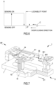
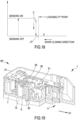
- the safety module 1 is arranged within the door-locking device BP generally installed in a washing machine or household appliance in general.
- the washing machine comprises a door, which in turn has a lug.
- the lug interacts with the door-locking device BP, as better explained below.
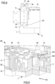
- said safety module 1 essentially comprises a containment casing 2, a locking pin 3, an activation unit 4, for activating the locking pin 3, an electric circuit 5, and a safety pin 6.
- the containment casing 2 comprises a base portion 21, which comprises cavities, within which various elements contained within the containment casing can be suitably housed, and a lid 22, arranged above said base portion 21 and able to fit with it.
- the locking pin 3 is capable of assuming a retracted position, in which it is contained within the safety module 1, and an extracted position, in which it is at least partially extracted from the safety module 1.
- the locking pin 3 when it is in said extracted position, projects from the lower surface of the base portion 31.
- the safety module 1 also comprises, as mentioned, an activation unit 4, configured to actuate the locking pin, so as to move it from said retracted position to said extracted position.
- Said activation unit 4 comprises a coil 41, connected to the control logic of the household appliance, in which the door-lock is installed, which comprises the safety module 1, a spring 42, and mechanical members 43 and 44, intended to allow the movement of said locking pin 3.
- the electrical circuit 5 is made with a main conductive plate 51, further connecting plates 52 and 53, and an elastic lamella 54, connected therebetween.
- the electric circuit 5 can be made with minor or major elements, plates or connectors.
- Said electrical circuit 5 includes a main switch 55, having a first electrode 551, arranged on said main conductive plate 51 and mechanically connected to said locking pin 3, and a second electrode 552, arranged fixed and obviously in correspondence with said first electrode 551, located on said connection plate 53. In this way, when said locking pin 3 is in said extracted position, the main switch 55 is closed, and therefore the first electrode 551 is in contact with the second electrode 552.
- Said electric circuit 5 also comprises a sensor switch 56, realized between the elastic lamella 54 and the main conductive plate 51.
- a slider 7 is arranged below the safety module 1.
- the slider 7 of the door-locking device BP has an opening 71 and a safety relief 72.
- the slider 7 is capable of interacting with the lug of a door, such that the lug moves the slider 7, so as to allow the relative movement of the same below said safety module 1.
- the opening 71 is arranged so as to overlap the locking pin 3 when the washing machine door is closed. In this configuration, said locking pin 3 can pass from the retracted position to the extracted position.
- the safety relief 72 raises the safety pin 6, as will be better explained below.
- the safety pin 6 comprises a body 61, having a cylindrical shape, at whose lower base two rotation reliefs 62 and 63 are arranged, placed eccentrically with respect to the axis of symmetry R of the cylinder body 61.
- the rotation relief 62 is arranged so as to interfere with the safety relief 72 of said slider 7 of the door-lock, to allow for the vertical translational motion and rotation of the safety pin 6, as will be explained in detail in the following.
- the safety pin comprises, on the upper base, a relief 64, intended to interfere with the elastic lamella 54, to raise or lower it, and a flap 65, intended to interfere with the main conductive plate 51, as better explained below.
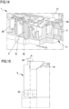
- the safety module 1 is located in the open door configuration, in which the locking pin 3 is retracted. Therefore, the main switch 55 is open, and the slider 7 is located in such a position as to overlap with the safety pin 6, so as to prevent with its own encumbrance the even accidental passage from the open position to the closed position.
- the safety pin 6 is kept raised by the safety relief 72 of the slider 7, so as to also keep open the sensor switch 56.
- a Cartesian diagram can be observed having on the abscissas the position of the lug of the household appliance door, such that, as shown in the figure, the shift to the left of the indicator (the circle indicated with the letter C) indicates that the door is closed.
- the point LP indicates the position of the lug beyond which the door can be closed, i.e., the opening 71 of the slider is overlapped on the locking pin 3, so as to allow its extraction, if necessary.
- the graph on the ordinate shows the state of the sensor 56, which can assume an open position (or “off”, as shown in figures 2 or 4 ), or closed (or “on”, as explained in detail later).
- the slider 7 is moved in the direction D2, opposite to the direction D1.
- the position of the slider 7 is such as to allow the overlapping of the locking pin 3 over the window 72 of the slider 7 and to allow, if necessary, the passage from the retracted position to the extracted position.
- Figure 10 shows the position of the indicator C at the point LP, where the door can be locked. In this position, the sensor pin 6 keeps the sensor switch 56 open, while still keeping the elastic lamella 54 raised, due to the safety relief 72.
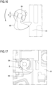
- the sensor pin 6 is lowered (see figure 11 ), until the sensor switch 56 closes, as can also be seen in figure 12 , in which the indicator C is in the position that indicates the closure (or "on" position) of the sensor switch 56.
- the sensor pin 6 assumes a first position, making a clockwise rotation (seen from above), such as to allow the disengagement of the flap 65 from said main conductive plate 51.
- the control logic moves the locking pin 3 by means of the coil 41 of the activation unit 4.
- the slider is free to move in the direction D1, since the locking pin 3 is retracted. In this way, the safety pin 6 is also raised, thanks to the action of the safety relief 72. In this way, the safety pin 6 opens the sensor switch 56.
- the safety relief 72 interferes with the rotation relief 62 of the safety pin 6, which, as mentioned, is arranged eccentrically with respect to the symmetry axis R of the safety pin 6 itself, the latter undergoes a sort of counter-clockwise rotation of an angle ⁇ , as can be seen in particular in figure 16 .
- the pin passes from a first position, as indicated above, in which the flap 65 does not interfere with the main conductive plate 51, to a second position, in which said flap 65 interferes with the edge of the main conductive plate 51. Since, as mentioned, the locking pin 3 is located in the retracted position, that means that the main conductive plate 51, on which the first electrode 551 of the main switch 55 is located, has such an inclination to act as a stop for the rotation of the sensor pin 6, which, as mentioned, opens the sensor switch 56.
- This rotation implies a sort of quantity indicated by X in figure 18 at the point of contact of the sensor pin 6 with the slider 7.
- the safety pin 6 rotates at least in part, moving by the aforementioned quantity X, before the main conductive plate 51 blocks its movement, resisting the bending caused by the flap 65.
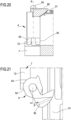
- the locking pin 3 is in the extracted position and therefore engaged with said slider 7, being inserted into said opening 71.
- the main conductive plate 51 is, as mentioned, in the lowered position. This involves that the safety pin 6 rotates by a second angle ⁇ (see figure 21 ), greater than the aforementioned first angle ⁇ , before interfering with the edge of the main conductive plate 51, precisely because said main conductive plate 51 is lowered. This rotation implies that the safety pin 6 is raised after the slider 7 travels of an additional space of X + Y, i.e., given by the sum of the displacements of X and Y, shown in figure 23 .
- An advantage of the present invention is that of allowing the realization of a safer door lock,0 which allows avoiding the opening the safety switch while the door is locked.
Landscapes
- Engineering & Computer Science (AREA)
- Textile Engineering (AREA)
- Mechanical Engineering (AREA)
- Main Body Construction Of Washing Machines And Laundry Dryers (AREA)
Claims (7)
- Türverriegelungsvorrichtung (BP) für ein Haushaltsgerät, wie z.B. eine Waschmaschine, einen Geschirrspüler und dergleichen, des Typs mit einer Tür, mit einem Ansatz, wobei die Türverriegelungsvorrichtung umfasst einen Schieber (7), der so angeordnet ist, dass er eine Freigabe- und eine Eingriffsposition mit der Lasche der Haushaltsgerätetür einnimmt, einem Detektions- und Sicherheitsmodul (1), mit eine leitende Hauptplatte (51), einen Verriegelungsstift (3), der eine eingezogene Stellung und eine ausgezogene Stellung einnehmen kann und in der Lage ist, mit dem Schieber (7) in Eingriff zu kommen, wenn er sich in der Eingriffsstellung befindet, einen Hauptschalter (55), der auf der leitenden Hauptplatte (51) angeordnet ist, um geöffnet zu werden, wenn sich der Verriegelungsstift (3) in der eingezogenen Position befindet, und um geschlossen zu werden, wenn sich der Verriegelungsstift (3) in der ausgezogenen Position befindet, wobei, wenn der Hauptschalter (55) geschlossen ist, anzeigt, dass der Schieber (7) durch den Verriegelungsstift (3) in der Eingriffsposition verriegelt ist, einen Sicherheitsstift (6), der in den Schieber (7) eingreift, so dass der Sicherheitsstift (6) den Sensorschalter (56) schließt, wenn sich der Schieber (7) von der Ausrückposition in die Einrückposition bewegt, wobei der Sicherheitsstift (6) eine untere Aussparung (62) umfasst, die so angeordnet ist, dass der Sicherheitsstift (6) gedreht wird, wenn der Schieber (7) in die untere Aussparung (62) eingreift, gekennzeichnet dass das Erfassungs- und Sicherheitsmodul (1) auch einen Sensorschalter (56) aufweist, der in Reihe mit dem Hauptschalter (55) angeordnet ist, um, wenn er geschlossen ist, anzuzeigen, dass sich der Schieber (7) in der Eingriffsposition befindet, dass die leitende Hauptplatte (51) an dem Verriegelungsstift (3) befestigt ist, so dass, wenn der Verriegelungsstift (3) in der eingezogenen Position ist, die leitende Hauptplatte (51) in einer ersten Position ist, stattdessen, wenn der Verriegelungsstift (3) in der ausgezogenen Position ist, die leitende Hauptplatte (51) in einer zweiten Position ist, und dass der Sicherheitsstift außerdem eine Klappe (65) aufweist, die so angeordnet ist, dass sie bei der Drehung des Sicherheitsstifts (6) in die leitende Hauptplatte (51) eingreift, wobei sich die Drehung des Sicherheitsstifts (6) in Abhängigkeit von der Position der leitenden Hauptplatte (51) ändert.
- Vorrichtung (BP) nach dem vorhergehenden Anspruch, dadurch gekennzeichnet, dass der Schieber (7) eine Sicherheitsentlastung (72) aufweist, die mit der unteren Entlastung (62) zusammenwirkt, wenn sich der Schieber (7) von der Freigabeposition zur Eingriffsposition bewegt.
- Vorrichtung (BP) nach einem der vorhergehenden Ansprüche, dadurch gekennzeichnet, dass der Sicherheitsstift (6) einen Körper (61) mit zylindrischer Form, einer Symmetrieachse (R), einer unteren Basis und einer oberen Basis umfasst, wobei das Rotationsrelief (62) auf der unteren Basis exzentrisch in Bezug auf die Symmetrieachse (R) angeordnet ist, und wobei die Klappe (65) in Übereinstimmung mit der oberen Fläche angeordnet ist.
- Vorrichtung (BP) nach dem vorhergehenden Anspruch, dadurch gekennzeichnet, dass der Sicherheitsstift (6) ein zweites Rotationsrelief (63) aufweist, das exzentrisch in Bezug auf die Symmetrieachse (R) angeordnet ist.
- Vorrichtung (BP) nach einem der vorhergehenden Ansprüche, dadurch gekennzeichnet dass sie eine elastische Lamelle (54) aufweist, die so angeordnet ist, dass sie mit dem oberen Ende des Sicherheitsstifts (6) zusammenwirkt, und dass der Sensorschalter (56) mittels der leitenden Hauptplatte (51) und der elastischen Lamelle (54) hergestellt wird.
- Vorrichtung (BP) nach dem vorhergehenden Anspruch, dadurch gekennzeichnet, dass der Sicherheitsstift (6) ein oberes Relief (64) aufweist, das dazu bestimmt ist, in die elastische Lamelle (54) einzugreifen, um sie anzuheben oder abzusenken.
- Vorrichtung (DP) nach einem der vorhergehenden Ansprüche, dadurch gekennzeichnet, dass der Schieber (7) eine Öffnung (71) aufweist, die so angeordnet ist, dass, wenn sich der Schieber (7) in der Eingriffsposition befindet, die Öffnung in Übereinstimmung mit dem Verriegelungsstift (3) angeordnet ist, was die Bewegung des Verriegelungsstifts (3) von der zurückgezogenen Position in die ausgezogene Position ermöglicht.
Applications Claiming Priority (1)
| Application Number | Priority Date | Filing Date | Title |
|---|---|---|---|
| IT202000012178 | 2020-05-25 |
Publications (3)
| Publication Number | Publication Date |
|---|---|
| EP3916145A1 EP3916145A1 (de) | 2021-12-01 |
| EP3916145C0 EP3916145C0 (de) | 2025-04-16 |
| EP3916145B1 true EP3916145B1 (de) | 2025-04-16 |
Family
ID=71994974
Family Applications (1)
| Application Number | Title | Priority Date | Filing Date |
|---|---|---|---|
| EP21172037.0A Active EP3916145B1 (de) | 2020-05-25 | 2021-05-04 | Türverriegelungsvorrichtung mit verbessertem sicherheitsmodul |
Country Status (4)
| Country | Link |
|---|---|
| US (1) | US11952802B2 (de) |
| EP (1) | EP3916145B1 (de) |
| KR (1) | KR102809799B1 (de) |
| CN (1) | CN113718486B (de) |
Family Cites Families (6)
| Publication number | Priority date | Publication date | Assignee | Title |
|---|---|---|---|---|
| IT994158B (it) * | 1973-08-21 | 1975-10-20 | Texas Instruments Italia Spa | Dispositivo di bloccaggio con interruttore ritardatore termico ad azionamento voltmetrico per sportelli |
| ITTO20120291A1 (it) * | 2012-04-03 | 2013-10-04 | Illinois Tool Works | Dispositivo di bloccaggio porta con interruttore di rilevamento porta integrato |
| ITRM20130017A1 (it) * | 2013-01-10 | 2014-07-11 | Bitron Spa | Dispositivo blocco-porta ad attivazione magnetica. |
| DE102016008317B4 (de) * | 2016-07-07 | 2018-10-31 | Emz-Hanauer Gmbh & Co. Kgaa | Türverschluss für ein elektrisches Haushaltsgerät |
| IT201700039100A1 (it) * | 2017-04-10 | 2018-10-10 | Bitron Spa | Dispositivo blocca-porta, particolarmente per apparecchi elettrodomestici. |
| KR102385798B1 (ko) * | 2017-05-17 | 2022-04-14 | 삼성전자주식회사 | 세탁기 및 세탁기의 제어 방법 |
-
2021
- 2021-05-04 EP EP21172037.0A patent/EP3916145B1/de active Active
- 2021-05-24 US US17/328,391 patent/US11952802B2/en active Active
- 2021-05-25 KR KR1020210066896A patent/KR102809799B1/ko active Active
- 2021-05-25 CN CN202110573640.1A patent/CN113718486B/zh active Active
Also Published As
| Publication number | Publication date |
|---|---|
| KR20210145689A (ko) | 2021-12-02 |
| US11952802B2 (en) | 2024-04-09 |
| EP3916145C0 (de) | 2025-04-16 |
| CN113718486B (zh) | 2026-02-10 |
| US20210363786A1 (en) | 2021-11-25 |
| KR102809799B1 (ko) | 2025-05-19 |
| CN113718486A (zh) | 2021-11-30 |
| EP3916145A1 (de) | 2021-12-01 |
Similar Documents
| Publication | Publication Date | Title |
|---|---|---|
| KR101779158B1 (ko) | 자기 조작-방지 특징을 가진 뚜껑 잠금 장치 | |
| US10914026B2 (en) | Door lock for home appliance with hook sensing mechanism | |
| EP3541984B1 (de) | Türschloss mit einem hakenerkennungsschieber mit zusätzlicher sicherheit | |
| WO2013181289A9 (en) | Electromagnetic door-lock | |
| US20080106105A1 (en) | Door Lock For The Door Of A Household Appliance | |
| EP2475815A1 (de) | Gerätesperre mit mechanischem türsensor | |
| CN110043146B (zh) | 一种按压式门锁 | |
| CN103334647B (zh) | 机电双控密码防盗锁 | |
| US11220779B2 (en) | Door-lock with door sensing | |
| EP3916145B1 (de) | Türverriegelungsvorrichtung mit verbessertem sicherheitsmodul | |
| WO2013124873A2 (en) | Door-lock device for a door of a household appliance | |
| US20200115927A1 (en) | Appliance lock with magnetic sensing switch actuation in a hydrophobic enclosure | |
| KR20220002377A (ko) | 도어 특히 세탁물 처리용 가전제품의 도어를 개폐하는 장치 | |
| EP1703212B1 (de) | Türschlossvorrichtung für ein Haushaltsgerät, insbesondere Backofen | |
| EP1640493A2 (de) | Türverriegelung für einen Haushaltsgerät | |
| KR102754239B1 (ko) | 가전 제품의 도어를 잠그기 위한 도어 잠금 장치 | |
| EP3312333B1 (de) | Doppelt türschlossvorrichtung für eine tür eines haushaltsgeräts | |
| EP3714093B1 (de) | Vorrichtung zum schliessen und öffnen von paneelen, insbesondere von paneelen elektrischer haushaltsgeräte wie etwa waschmaschinen und dergleichen | |
| WO2009061628A1 (en) | Appliance latch with compact form factor | |
| KR102916225B1 (ko) | 도어락 장치 | |
| KR102756731B1 (ko) | 무동력 지진감지 엑추에이터 | |
| EP4459032B1 (de) | Haushaltsgerät mit notöffnungs- und notöffnungsvorrichtung | |
| EP3426837B1 (de) | Türschloss mit türerfassung | |
| US11732503B2 (en) | Device for closing and opening and/or for locking and unlocking doors, in particular doors of household appliances such as washing machines or the like | |
| WO2024028787A1 (en) | Space-saving device with automatic opening function for opening and closing a dishwasher door |
Legal Events
| Date | Code | Title | Description |
|---|---|---|---|
| PUAI | Public reference made under article 153(3) epc to a published international application that has entered the european phase |
Free format text: ORIGINAL CODE: 0009012 |
|
| STAA | Information on the status of an ep patent application or granted ep patent |
Free format text: STATUS: THE APPLICATION HAS BEEN PUBLISHED |
|
| AK | Designated contracting states |
Kind code of ref document: A1 Designated state(s): AL AT BE BG CH CY CZ DE DK EE ES FI FR GB GR HR HU IE IS IT LI LT LU LV MC MK MT NL NO PL PT RO RS SE SI SK SM TR |
|
| B565 | Issuance of search results under rule 164(2) epc |
Effective date: 20210602 |
|
| STAA | Information on the status of an ep patent application or granted ep patent |
Free format text: STATUS: REQUEST FOR EXAMINATION WAS MADE |
|
| 17P | Request for examination filed |
Effective date: 20220309 |
|
| RBV | Designated contracting states (corrected) |
Designated state(s): AL AT BE BG CH CY CZ DE DK EE ES FI FR GB GR HR HU IE IS IT LI LT LU LV MC MK MT NL NO PL PT RO RS SE SI SK SM TR |
|
| RAP1 | Party data changed (applicant data changed or rights of an application transferred) |
Owner name: ELBI INTERNATIONAL S.P.A. |
|
| GRAP | Despatch of communication of intention to grant a patent |
Free format text: ORIGINAL CODE: EPIDOSNIGR1 |
|
| RAP3 | Party data changed (applicant data changed or rights of an application transferred) |
Owner name: ELBI INTERNATIONAL S.P.A. |
|
| STAA | Information on the status of an ep patent application or granted ep patent |
Free format text: STATUS: GRANT OF PATENT IS INTENDED |
|
| RIC1 | Information provided on ipc code assigned before grant |
Ipc: A47L 15/42 20060101ALN20241204BHEP Ipc: D06F 39/14 20060101ALN20241204BHEP Ipc: D06F 37/42 20060101AFI20241204BHEP |
|
| INTG | Intention to grant announced |
Effective date: 20241212 |
|
| GRAS | Grant fee paid |
Free format text: ORIGINAL CODE: EPIDOSNIGR3 |
|
| GRAA | (expected) grant |
Free format text: ORIGINAL CODE: 0009210 |
|
| STAA | Information on the status of an ep patent application or granted ep patent |
Free format text: STATUS: THE PATENT HAS BEEN GRANTED |
|
| AK | Designated contracting states |
Kind code of ref document: B1 Designated state(s): AL AT BE BG CH CY CZ DE DK EE ES FI FR GB GR HR HU IE IS IT LI LT LU LV MC MK MT NL NO PL PT RO RS SE SI SK SM TR |
|
| REG | Reference to a national code |
Ref country code: GB Ref legal event code: FG4D |
|
| REG | Reference to a national code |
Ref country code: CH Ref legal event code: EP Ref country code: DE Ref legal event code: R096 Ref document number: 602021029113 Country of ref document: DE |
|
| REG | Reference to a national code |
Ref country code: IE Ref legal event code: FG4D |
|
| U01 | Request for unitary effect filed |
Effective date: 20250509 |
|
| U07 | Unitary effect registered |
Designated state(s): AT BE BG DE DK EE FI FR IT LT LU LV MT NL PT RO SE SI Effective date: 20250516 |
|
| U20 | Renewal fee for the european patent with unitary effect paid |
Year of fee payment: 5 Effective date: 20250516 |
|
| PG25 | Lapsed in a contracting state [announced via postgrant information from national office to epo] |
Ref country code: ES Free format text: LAPSE BECAUSE OF FAILURE TO SUBMIT A TRANSLATION OF THE DESCRIPTION OR TO PAY THE FEE WITHIN THE PRESCRIBED TIME-LIMIT Effective date: 20250416 |
|
| PG25 | Lapsed in a contracting state [announced via postgrant information from national office to epo] |
Ref country code: NO Free format text: LAPSE BECAUSE OF FAILURE TO SUBMIT A TRANSLATION OF THE DESCRIPTION OR TO PAY THE FEE WITHIN THE PRESCRIBED TIME-LIMIT Effective date: 20250716 Ref country code: GR Free format text: LAPSE BECAUSE OF FAILURE TO SUBMIT A TRANSLATION OF THE DESCRIPTION OR TO PAY THE FEE WITHIN THE PRESCRIBED TIME-LIMIT Effective date: 20250717 |
|
| PG25 | Lapsed in a contracting state [announced via postgrant information from national office to epo] |
Ref country code: PL Free format text: LAPSE BECAUSE OF FAILURE TO SUBMIT A TRANSLATION OF THE DESCRIPTION OR TO PAY THE FEE WITHIN THE PRESCRIBED TIME-LIMIT Effective date: 20250416 |
|
| PG25 | Lapsed in a contracting state [announced via postgrant information from national office to epo] |
Ref country code: HR Free format text: LAPSE BECAUSE OF FAILURE TO SUBMIT A TRANSLATION OF THE DESCRIPTION OR TO PAY THE FEE WITHIN THE PRESCRIBED TIME-LIMIT Effective date: 20250416 |
|
| PG25 | Lapsed in a contracting state [announced via postgrant information from national office to epo] |
Ref country code: RS Free format text: LAPSE BECAUSE OF FAILURE TO SUBMIT A TRANSLATION OF THE DESCRIPTION OR TO PAY THE FEE WITHIN THE PRESCRIBED TIME-LIMIT Effective date: 20250716 |
|
| PG25 | Lapsed in a contracting state [announced via postgrant information from national office to epo] |
Ref country code: IS Free format text: LAPSE BECAUSE OF FAILURE TO SUBMIT A TRANSLATION OF THE DESCRIPTION OR TO PAY THE FEE WITHIN THE PRESCRIBED TIME-LIMIT Effective date: 20250816 |
|
| REG | Reference to a national code |
Ref country code: CH Ref legal event code: H13 Free format text: ST27 STATUS EVENT CODE: U-0-0-H10-H13 (AS PROVIDED BY THE NATIONAL OFFICE) Effective date: 20251223 |
|
| PG25 | Lapsed in a contracting state [announced via postgrant information from national office to epo] |
Ref country code: SM Free format text: LAPSE BECAUSE OF FAILURE TO SUBMIT A TRANSLATION OF THE DESCRIPTION OR TO PAY THE FEE WITHIN THE PRESCRIBED TIME-LIMIT Effective date: 20250416 |
|
| PG25 | Lapsed in a contracting state [announced via postgrant information from national office to epo] |
Ref country code: CH Free format text: LAPSE BECAUSE OF NON-PAYMENT OF DUE FEES Effective date: 20250531 |
|
| PG25 | Lapsed in a contracting state [announced via postgrant information from national office to epo] |
Ref country code: CZ Free format text: LAPSE BECAUSE OF FAILURE TO SUBMIT A TRANSLATION OF THE DESCRIPTION OR TO PAY THE FEE WITHIN THE PRESCRIBED TIME-LIMIT Effective date: 20250416 |
|
| PG25 | Lapsed in a contracting state [announced via postgrant information from national office to epo] |
Ref country code: SK Free format text: LAPSE BECAUSE OF FAILURE TO SUBMIT A TRANSLATION OF THE DESCRIPTION OR TO PAY THE FEE WITHIN THE PRESCRIBED TIME-LIMIT Effective date: 20250416 |
|
| PG25 | Lapsed in a contracting state [announced via postgrant information from national office to epo] |
Ref country code: MC Free format text: LAPSE BECAUSE OF FAILURE TO SUBMIT A TRANSLATION OF THE DESCRIPTION OR TO PAY THE FEE WITHIN THE PRESCRIBED TIME-LIMIT Effective date: 20250416 |
|
| PLBE | No opposition filed within time limit |
Free format text: ORIGINAL CODE: 0009261 |
|
| STAA | Information on the status of an ep patent application or granted ep patent |
Free format text: STATUS: NO OPPOSITION FILED WITHIN TIME LIMIT |
|
| REG | Reference to a national code |
Ref country code: CH Ref legal event code: L10 Free format text: ST27 STATUS EVENT CODE: U-0-0-L10-L00 (AS PROVIDED BY THE NATIONAL OFFICE) Effective date: 20260225 |