EP3916113A1 - Non-oriented electromagnetic steel sheet and method for producing same - Google Patents
Non-oriented electromagnetic steel sheet and method for producing same Download PDFInfo
- Publication number
- EP3916113A1 EP3916113A1 EP20745534.6A EP20745534A EP3916113A1 EP 3916113 A1 EP3916113 A1 EP 3916113A1 EP 20745534 A EP20745534 A EP 20745534A EP 3916113 A1 EP3916113 A1 EP 3916113A1
- Authority
- EP
- European Patent Office
- Prior art keywords
- mass
- rolling
- strength
- steel sheet
- steel
- Prior art date
- Legal status (The legal status is an assumption and is not a legal conclusion. Google has not performed a legal analysis and makes no representation as to the accuracy of the status listed.)
- Pending
Links
Images

Classifications
-
- C—CHEMISTRY; METALLURGY
- C22—METALLURGY; FERROUS OR NON-FERROUS ALLOYS; TREATMENT OF ALLOYS OR NON-FERROUS METALS
- C22C—ALLOYS
- C22C38/00—Ferrous alloys, e.g. steel alloys
- C22C38/004—Very low carbon steels, i.e. having a carbon content of less than 0,01%
-
- C—CHEMISTRY; METALLURGY
- C21—METALLURGY OF IRON
- C21D—MODIFYING THE PHYSICAL STRUCTURE OF FERROUS METALS; GENERAL DEVICES FOR HEAT TREATMENT OF FERROUS OR NON-FERROUS METALS OR ALLOYS; MAKING METAL MALLEABLE, e.g. BY DECARBURISATION OR TEMPERING
- C21D8/00—Modifying the physical properties of ferrous metals or ferrous alloys by deformation combined with, or followed by, heat treatment
- C21D8/12—Modifying the physical properties of ferrous metals or ferrous alloys by deformation combined with, or followed by, heat treatment during manufacturing of articles with special electromagnetic properties
- C21D8/1216—Modifying the physical properties of ferrous metals or ferrous alloys by deformation combined with, or followed by, heat treatment during manufacturing of articles with special electromagnetic properties characterised by the working steps
- C21D8/1222—Hot rolling
-
- C—CHEMISTRY; METALLURGY
- C21—METALLURGY OF IRON
- C21D—MODIFYING THE PHYSICAL STRUCTURE OF FERROUS METALS; GENERAL DEVICES FOR HEAT TREATMENT OF FERROUS OR NON-FERROUS METALS OR ALLOYS; MAKING METAL MALLEABLE, e.g. BY DECARBURISATION OR TEMPERING
- C21D1/00—General methods or devices for heat treatment, e.g. annealing, hardening, quenching or tempering
- C21D1/26—Methods of annealing
-
- C—CHEMISTRY; METALLURGY
- C21—METALLURGY OF IRON
- C21D—MODIFYING THE PHYSICAL STRUCTURE OF FERROUS METALS; GENERAL DEVICES FOR HEAT TREATMENT OF FERROUS OR NON-FERROUS METALS OR ALLOYS; MAKING METAL MALLEABLE, e.g. BY DECARBURISATION OR TEMPERING
- C21D1/00—General methods or devices for heat treatment, e.g. annealing, hardening, quenching or tempering
- C21D1/26—Methods of annealing
- C21D1/30—Stress-relieving
-
- C—CHEMISTRY; METALLURGY
- C21—METALLURGY OF IRON
- C21D—MODIFYING THE PHYSICAL STRUCTURE OF FERROUS METALS; GENERAL DEVICES FOR HEAT TREATMENT OF FERROUS OR NON-FERROUS METALS OR ALLOYS; MAKING METAL MALLEABLE, e.g. BY DECARBURISATION OR TEMPERING
- C21D6/00—Heat treatment of ferrous alloys
- C21D6/005—Heat treatment of ferrous alloys containing Mn
-
- C—CHEMISTRY; METALLURGY
- C21—METALLURGY OF IRON
- C21D—MODIFYING THE PHYSICAL STRUCTURE OF FERROUS METALS; GENERAL DEVICES FOR HEAT TREATMENT OF FERROUS OR NON-FERROUS METALS OR ALLOYS; MAKING METAL MALLEABLE, e.g. BY DECARBURISATION OR TEMPERING
- C21D6/00—Heat treatment of ferrous alloys
- C21D6/008—Heat treatment of ferrous alloys containing Si
-
- C—CHEMISTRY; METALLURGY
- C21—METALLURGY OF IRON
- C21D—MODIFYING THE PHYSICAL STRUCTURE OF FERROUS METALS; GENERAL DEVICES FOR HEAT TREATMENT OF FERROUS OR NON-FERROUS METALS OR ALLOYS; MAKING METAL MALLEABLE, e.g. BY DECARBURISATION OR TEMPERING
- C21D8/00—Modifying the physical properties of ferrous metals or ferrous alloys by deformation combined with, or followed by, heat treatment
-
- C—CHEMISTRY; METALLURGY
- C21—METALLURGY OF IRON
- C21D—MODIFYING THE PHYSICAL STRUCTURE OF FERROUS METALS; GENERAL DEVICES FOR HEAT TREATMENT OF FERROUS OR NON-FERROUS METALS OR ALLOYS; MAKING METAL MALLEABLE, e.g. BY DECARBURISATION OR TEMPERING
- C21D8/00—Modifying the physical properties of ferrous metals or ferrous alloys by deformation combined with, or followed by, heat treatment
- C21D8/12—Modifying the physical properties of ferrous metals or ferrous alloys by deformation combined with, or followed by, heat treatment during manufacturing of articles with special electromagnetic properties
- C21D8/1216—Modifying the physical properties of ferrous metals or ferrous alloys by deformation combined with, or followed by, heat treatment during manufacturing of articles with special electromagnetic properties characterised by the working steps
- C21D8/1233—Cold rolling
-
- C—CHEMISTRY; METALLURGY
- C21—METALLURGY OF IRON
- C21D—MODIFYING THE PHYSICAL STRUCTURE OF FERROUS METALS; GENERAL DEVICES FOR HEAT TREATMENT OF FERROUS OR NON-FERROUS METALS OR ALLOYS; MAKING METAL MALLEABLE, e.g. BY DECARBURISATION OR TEMPERING
- C21D8/00—Modifying the physical properties of ferrous metals or ferrous alloys by deformation combined with, or followed by, heat treatment
- C21D8/12—Modifying the physical properties of ferrous metals or ferrous alloys by deformation combined with, or followed by, heat treatment during manufacturing of articles with special electromagnetic properties
- C21D8/1244—Modifying the physical properties of ferrous metals or ferrous alloys by deformation combined with, or followed by, heat treatment during manufacturing of articles with special electromagnetic properties characterised by the heat treatment
-
- C—CHEMISTRY; METALLURGY
- C21—METALLURGY OF IRON
- C21D—MODIFYING THE PHYSICAL STRUCTURE OF FERROUS METALS; GENERAL DEVICES FOR HEAT TREATMENT OF FERROUS OR NON-FERROUS METALS OR ALLOYS; MAKING METAL MALLEABLE, e.g. BY DECARBURISATION OR TEMPERING
- C21D8/00—Modifying the physical properties of ferrous metals or ferrous alloys by deformation combined with, or followed by, heat treatment
- C21D8/12—Modifying the physical properties of ferrous metals or ferrous alloys by deformation combined with, or followed by, heat treatment during manufacturing of articles with special electromagnetic properties
- C21D8/1244—Modifying the physical properties of ferrous metals or ferrous alloys by deformation combined with, or followed by, heat treatment during manufacturing of articles with special electromagnetic properties characterised by the heat treatment
- C21D8/1261—Modifying the physical properties of ferrous metals or ferrous alloys by deformation combined with, or followed by, heat treatment during manufacturing of articles with special electromagnetic properties characterised by the heat treatment following hot rolling
-
- C—CHEMISTRY; METALLURGY
- C21—METALLURGY OF IRON
- C21D—MODIFYING THE PHYSICAL STRUCTURE OF FERROUS METALS; GENERAL DEVICES FOR HEAT TREATMENT OF FERROUS OR NON-FERROUS METALS OR ALLOYS; MAKING METAL MALLEABLE, e.g. BY DECARBURISATION OR TEMPERING
- C21D8/00—Modifying the physical properties of ferrous metals or ferrous alloys by deformation combined with, or followed by, heat treatment
- C21D8/12—Modifying the physical properties of ferrous metals or ferrous alloys by deformation combined with, or followed by, heat treatment during manufacturing of articles with special electromagnetic properties
- C21D8/1244—Modifying the physical properties of ferrous metals or ferrous alloys by deformation combined with, or followed by, heat treatment during manufacturing of articles with special electromagnetic properties characterised by the heat treatment
- C21D8/1266—Modifying the physical properties of ferrous metals or ferrous alloys by deformation combined with, or followed by, heat treatment during manufacturing of articles with special electromagnetic properties characterised by the heat treatment between cold rolling steps
-
- C—CHEMISTRY; METALLURGY
- C21—METALLURGY OF IRON
- C21D—MODIFYING THE PHYSICAL STRUCTURE OF FERROUS METALS; GENERAL DEVICES FOR HEAT TREATMENT OF FERROUS OR NON-FERROUS METALS OR ALLOYS; MAKING METAL MALLEABLE, e.g. BY DECARBURISATION OR TEMPERING
- C21D8/00—Modifying the physical properties of ferrous metals or ferrous alloys by deformation combined with, or followed by, heat treatment
- C21D8/12—Modifying the physical properties of ferrous metals or ferrous alloys by deformation combined with, or followed by, heat treatment during manufacturing of articles with special electromagnetic properties
- C21D8/1244—Modifying the physical properties of ferrous metals or ferrous alloys by deformation combined with, or followed by, heat treatment during manufacturing of articles with special electromagnetic properties characterised by the heat treatment
- C21D8/1272—Final recrystallisation annealing
-
- C—CHEMISTRY; METALLURGY
- C21—METALLURGY OF IRON
- C21D—MODIFYING THE PHYSICAL STRUCTURE OF FERROUS METALS; GENERAL DEVICES FOR HEAT TREATMENT OF FERROUS OR NON-FERROUS METALS OR ALLOYS; MAKING METAL MALLEABLE, e.g. BY DECARBURISATION OR TEMPERING
- C21D9/00—Heat treatment, e.g. annealing, hardening, quenching or tempering, adapted for particular articles; Furnaces therefor
- C21D9/46—Heat treatment, e.g. annealing, hardening, quenching or tempering, adapted for particular articles; Furnaces therefor for sheet metals
-
- C—CHEMISTRY; METALLURGY
- C22—METALLURGY; FERROUS OR NON-FERROUS ALLOYS; TREATMENT OF ALLOYS OR NON-FERROUS METALS
- C22C—ALLOYS
- C22C38/00—Ferrous alloys, e.g. steel alloys
- C22C38/001—Ferrous alloys, e.g. steel alloys containing N
-
- C—CHEMISTRY; METALLURGY
- C22—METALLURGY; FERROUS OR NON-FERROUS ALLOYS; TREATMENT OF ALLOYS OR NON-FERROUS METALS
- C22C—ALLOYS
- C22C38/00—Ferrous alloys, e.g. steel alloys
- C22C38/002—Ferrous alloys, e.g. steel alloys containing In, Mg, or other elements not provided for in one single group C22C38/001 - C22C38/60
-
- C—CHEMISTRY; METALLURGY
- C22—METALLURGY; FERROUS OR NON-FERROUS ALLOYS; TREATMENT OF ALLOYS OR NON-FERROUS METALS
- C22C—ALLOYS
- C22C38/00—Ferrous alloys, e.g. steel alloys
- C22C38/005—Ferrous alloys, e.g. steel alloys containing rare earths, i.e. Sc, Y, Lanthanides
-
- C—CHEMISTRY; METALLURGY
- C22—METALLURGY; FERROUS OR NON-FERROUS ALLOYS; TREATMENT OF ALLOYS OR NON-FERROUS METALS
- C22C—ALLOYS
- C22C38/00—Ferrous alloys, e.g. steel alloys
- C22C38/008—Ferrous alloys, e.g. steel alloys containing tin
-
- C—CHEMISTRY; METALLURGY
- C22—METALLURGY; FERROUS OR NON-FERROUS ALLOYS; TREATMENT OF ALLOYS OR NON-FERROUS METALS
- C22C—ALLOYS
- C22C38/00—Ferrous alloys, e.g. steel alloys
- C22C38/02—Ferrous alloys, e.g. steel alloys containing silicon
-
- C—CHEMISTRY; METALLURGY
- C22—METALLURGY; FERROUS OR NON-FERROUS ALLOYS; TREATMENT OF ALLOYS OR NON-FERROUS METALS
- C22C—ALLOYS
- C22C38/00—Ferrous alloys, e.g. steel alloys
- C22C38/04—Ferrous alloys, e.g. steel alloys containing manganese
-
- C—CHEMISTRY; METALLURGY
- C22—METALLURGY; FERROUS OR NON-FERROUS ALLOYS; TREATMENT OF ALLOYS OR NON-FERROUS METALS
- C22C—ALLOYS
- C22C38/00—Ferrous alloys, e.g. steel alloys
- C22C38/06—Ferrous alloys, e.g. steel alloys containing aluminium
-
- C—CHEMISTRY; METALLURGY
- C22—METALLURGY; FERROUS OR NON-FERROUS ALLOYS; TREATMENT OF ALLOYS OR NON-FERROUS METALS
- C22C—ALLOYS
- C22C38/00—Ferrous alloys, e.g. steel alloys
- C22C38/08—Ferrous alloys, e.g. steel alloys containing nickel
-
- C—CHEMISTRY; METALLURGY
- C22—METALLURGY; FERROUS OR NON-FERROUS ALLOYS; TREATMENT OF ALLOYS OR NON-FERROUS METALS
- C22C—ALLOYS
- C22C38/00—Ferrous alloys, e.g. steel alloys
- C22C38/10—Ferrous alloys, e.g. steel alloys containing cobalt
-
- C—CHEMISTRY; METALLURGY
- C22—METALLURGY; FERROUS OR NON-FERROUS ALLOYS; TREATMENT OF ALLOYS OR NON-FERROUS METALS
- C22C—ALLOYS
- C22C38/00—Ferrous alloys, e.g. steel alloys
- C22C38/12—Ferrous alloys, e.g. steel alloys containing tungsten, tantalum, molybdenum, vanadium, or niobium
-
- C—CHEMISTRY; METALLURGY
- C22—METALLURGY; FERROUS OR NON-FERROUS ALLOYS; TREATMENT OF ALLOYS OR NON-FERROUS METALS
- C22C—ALLOYS
- C22C38/00—Ferrous alloys, e.g. steel alloys
- C22C38/14—Ferrous alloys, e.g. steel alloys containing titanium or zirconium
-
- C—CHEMISTRY; METALLURGY
- C22—METALLURGY; FERROUS OR NON-FERROUS ALLOYS; TREATMENT OF ALLOYS OR NON-FERROUS METALS
- C22C—ALLOYS
- C22C38/00—Ferrous alloys, e.g. steel alloys
- C22C38/16—Ferrous alloys, e.g. steel alloys containing copper
-
- C—CHEMISTRY; METALLURGY
- C22—METALLURGY; FERROUS OR NON-FERROUS ALLOYS; TREATMENT OF ALLOYS OR NON-FERROUS METALS
- C22C—ALLOYS
- C22C38/00—Ferrous alloys, e.g. steel alloys
- C22C38/18—Ferrous alloys, e.g. steel alloys containing chromium
- C22C38/24—Ferrous alloys, e.g. steel alloys containing chromium with vanadium
-
- C—CHEMISTRY; METALLURGY
- C22—METALLURGY; FERROUS OR NON-FERROUS ALLOYS; TREATMENT OF ALLOYS OR NON-FERROUS METALS
- C22C—ALLOYS
- C22C38/00—Ferrous alloys, e.g. steel alloys
- C22C38/18—Ferrous alloys, e.g. steel alloys containing chromium
- C22C38/26—Ferrous alloys, e.g. steel alloys containing chromium with niobium or tantalum
-
- C—CHEMISTRY; METALLURGY
- C22—METALLURGY; FERROUS OR NON-FERROUS ALLOYS; TREATMENT OF ALLOYS OR NON-FERROUS METALS
- C22C—ALLOYS
- C22C38/00—Ferrous alloys, e.g. steel alloys
- C22C38/18—Ferrous alloys, e.g. steel alloys containing chromium
- C22C38/28—Ferrous alloys, e.g. steel alloys containing chromium with titanium or zirconium
-
- C—CHEMISTRY; METALLURGY
- C22—METALLURGY; FERROUS OR NON-FERROUS ALLOYS; TREATMENT OF ALLOYS OR NON-FERROUS METALS
- C22C—ALLOYS
- C22C38/00—Ferrous alloys, e.g. steel alloys
- C22C38/18—Ferrous alloys, e.g. steel alloys containing chromium
- C22C38/34—Ferrous alloys, e.g. steel alloys containing chromium with more than 1.5% by weight of silicon
-
- C—CHEMISTRY; METALLURGY
- C22—METALLURGY; FERROUS OR NON-FERROUS ALLOYS; TREATMENT OF ALLOYS OR NON-FERROUS METALS
- C22C—ALLOYS
- C22C38/00—Ferrous alloys, e.g. steel alloys
- C22C38/18—Ferrous alloys, e.g. steel alloys containing chromium
- C22C38/40—Ferrous alloys, e.g. steel alloys containing chromium with nickel
- C22C38/50—Ferrous alloys, e.g. steel alloys containing chromium with nickel with titanium or zirconium
-
- C—CHEMISTRY; METALLURGY
- C22—METALLURGY; FERROUS OR NON-FERROUS ALLOYS; TREATMENT OF ALLOYS OR NON-FERROUS METALS
- C22C—ALLOYS
- C22C38/00—Ferrous alloys, e.g. steel alloys
- C22C38/18—Ferrous alloys, e.g. steel alloys containing chromium
- C22C38/40—Ferrous alloys, e.g. steel alloys containing chromium with nickel
- C22C38/58—Ferrous alloys, e.g. steel alloys containing chromium with nickel with more than 1.5% by weight of manganese
-
- C—CHEMISTRY; METALLURGY
- C22—METALLURGY; FERROUS OR NON-FERROUS ALLOYS; TREATMENT OF ALLOYS OR NON-FERROUS METALS
- C22C—ALLOYS
- C22C38/00—Ferrous alloys, e.g. steel alloys
- C22C38/60—Ferrous alloys, e.g. steel alloys containing lead, selenium, tellurium, or antimony, or more than 0.04% by weight of sulfur
-
- H—ELECTRICITY
- H01—ELECTRIC ELEMENTS
- H01F—MAGNETS; INDUCTANCES; TRANSFORMERS; SELECTION OF MATERIALS FOR THEIR MAGNETIC PROPERTIES
- H01F1/00—Magnets or magnetic bodies characterised by the magnetic materials therefor; Selection of materials for their magnetic properties
- H01F1/01—Magnets or magnetic bodies characterised by the magnetic materials therefor; Selection of materials for their magnetic properties of inorganic materials
- H01F1/03—Magnets or magnetic bodies characterised by the magnetic materials therefor; Selection of materials for their magnetic properties of inorganic materials characterised by their coercivity
- H01F1/12—Magnets or magnetic bodies characterised by the magnetic materials therefor; Selection of materials for their magnetic properties of inorganic materials characterised by their coercivity of soft-magnetic materials
- H01F1/14—Magnets or magnetic bodies characterised by the magnetic materials therefor; Selection of materials for their magnetic properties of inorganic materials characterised by their coercivity of soft-magnetic materials metals or alloys
- H01F1/147—Alloys characterised by their composition
-
- H—ELECTRICITY
- H01—ELECTRIC ELEMENTS
- H01F—MAGNETS; INDUCTANCES; TRANSFORMERS; SELECTION OF MATERIALS FOR THEIR MAGNETIC PROPERTIES
- H01F1/00—Magnets or magnetic bodies characterised by the magnetic materials therefor; Selection of materials for their magnetic properties
- H01F1/01—Magnets or magnetic bodies characterised by the magnetic materials therefor; Selection of materials for their magnetic properties of inorganic materials
- H01F1/03—Magnets or magnetic bodies characterised by the magnetic materials therefor; Selection of materials for their magnetic properties of inorganic materials characterised by their coercivity
- H01F1/12—Magnets or magnetic bodies characterised by the magnetic materials therefor; Selection of materials for their magnetic properties of inorganic materials characterised by their coercivity of soft-magnetic materials
- H01F1/14—Magnets or magnetic bodies characterised by the magnetic materials therefor; Selection of materials for their magnetic properties of inorganic materials characterised by their coercivity of soft-magnetic materials metals or alloys
- H01F1/16—Magnets or magnetic bodies characterised by the magnetic materials therefor; Selection of materials for their magnetic properties of inorganic materials characterised by their coercivity of soft-magnetic materials metals or alloys in the form of sheets
-
- C—CHEMISTRY; METALLURGY
- C22—METALLURGY; FERROUS OR NON-FERROUS ALLOYS; TREATMENT OF ALLOYS OR NON-FERROUS METALS
- C22C—ALLOYS
- C22C2202/00—Physical properties
- C22C2202/02—Magnetic
-
- H—ELECTRICITY
- H01—ELECTRIC ELEMENTS
- H01F—MAGNETS; INDUCTANCES; TRANSFORMERS; SELECTION OF MATERIALS FOR THEIR MAGNETIC PROPERTIES
- H01F1/00—Magnets or magnetic bodies characterised by the magnetic materials therefor; Selection of materials for their magnetic properties
- H01F1/01—Magnets or magnetic bodies characterised by the magnetic materials therefor; Selection of materials for their magnetic properties of inorganic materials
- H01F1/03—Magnets or magnetic bodies characterised by the magnetic materials therefor; Selection of materials for their magnetic properties of inorganic materials characterised by their coercivity
- H01F1/12—Magnets or magnetic bodies characterised by the magnetic materials therefor; Selection of materials for their magnetic properties of inorganic materials characterised by their coercivity of soft-magnetic materials
- H01F1/14—Magnets or magnetic bodies characterised by the magnetic materials therefor; Selection of materials for their magnetic properties of inorganic materials characterised by their coercivity of soft-magnetic materials metals or alloys
- H01F1/147—Alloys characterised by their composition
- H01F1/14766—Fe-Si based alloys
- H01F1/14791—Fe-Si-Al based alloys, e.g. Sendust
-
- Y—GENERAL TAGGING OF NEW TECHNOLOGICAL DEVELOPMENTS; GENERAL TAGGING OF CROSS-SECTIONAL TECHNOLOGIES SPANNING OVER SEVERAL SECTIONS OF THE IPC; TECHNICAL SUBJECTS COVERED BY FORMER USPC CROSS-REFERENCE ART COLLECTIONS [XRACs] AND DIGESTS
- Y02—TECHNOLOGIES OR APPLICATIONS FOR MITIGATION OR ADAPTATION AGAINST CLIMATE CHANGE
- Y02T—CLIMATE CHANGE MITIGATION TECHNOLOGIES RELATED TO TRANSPORTATION
- Y02T10/00—Road transport of goods or passengers
- Y02T10/60—Other road transportation technologies with climate change mitigation effect
- Y02T10/64—Electric machine technologies in electromobility
Definitions
- This invention relates to a non-oriented electrical steel sheet and a method for producing the same, and more particularly to a non-oriented electrical steel sheet having a high strength and a low iron loss and a method for producing the same.
- a motor core is formed of a stator core fixed in a motor case and a rotor core rotating at a high speed, and centrifugal force is generated in the rotating rotor core.
- the magnitude of the centrifugal force is proportional to radius of rotation and proportional to the square of the rotating speed. Accordingly, a steel sheet as a raw material of a middle- and large-size rotor cores rotating at a high speed is demanded to have a high strength.
- IPM motors are used in drive motors for electric vehicles, hybrid vehicles, etc., have a slit in the outer circumference of the rotor, and a magnet is embedded in the slit, where stress is concentrated in a narrow bridge portion supporting the magnet. Therefore, a steel sheet as a raw material of the rotor core, even a relatively small-size motor, is demanded to have a high strength.
- a method for attaining high strength includes, for example, a method of adding a large amount of a solid-solution strengthening element such as Si, Al and the like to iron and thus forming a high alloy steel. This method can attain low iron loss and high strength at the same time and is preferably used. There is another method of using precipitation strengthening to achieve high strength by forming a high alloy steel, but the method has a problem that the precipitated second phase grains considerably block the grain growth in finish annealing or stress-relief annealing. Moreover, as a method for attaining high strength other than by forming high alloy steel, there is widely used a method of increasing strength by making crystal grains finer.
- This method comprises forming a motor core using a high-strength material and subjecting only the stator core to stress-relief annealing so as to cause grain growth, resulting in an advantage that the stator core has a low iron loss while the rotor core has a high strength.
- Patent Literatures 1 and 2 propose a method of attaining high strength by using non-recrystallized texture.
- Patent Literature 3 proposes a method of controlling the configuration of non-recrystallized texture to suppress a variation in tensile strength and fatigue strength.
- Patent Literatures 1 and 2 The inventors have produced a non-oriented electrical steel sheet using a high-alloy steel as a raw material by applying the method disclosed in Patent Literatures 1 and 2, and as result, found that these methods have a problem that fatigue strength is largely varied. Although the method disclosed in Patent Literature 3 can suppress variations in tensile strength and fatigue strength, the Al and Mn contents are limited to a relatively low amount, causing a problem of low specific resistance and high iron loss at a high-frequency.
- the invention is made in consideration of the above problems inherent to the conventional methods, and an object thereof is to provide a non-oriented electrical steel sheet having a high strength (high tensile strength and high fatigue strength) and a low iron loss by using a high-alloy steel having a high Si and Al contents as a raw material and propose an advantageous method for producing the same.
- the inventors have made various studies, focusing on a combination technique of increasing the strength by using a high alloy steel material and increasing the strength by using a non-recrystallized texture. As a result, they have found that, in order to stably produce a non-oriented electrical steel sheet having a high strength (high tensile strength and high fatigue strength) and a low iron loss using the combination technique, it is effective to adjust the texture of a product sheet, and thus the invention has been accomplished.
- the invention based on the above knowledge is a non-oriented electrical steel sheet having a chemical composition comprising C: not more than 0.0050 mass%, Si: 3.2 to 5.0 mass%, Mn: not more than 2.0 mass%, P: not more than 0.02 mass%, S: not more than 0.0050 mass%, Al: 0.5 to 2.0 mass%, N: not more than 0.0050 mass%, Ti: not more than 0.0030 mass%, Nb: not more than 0.0010 mass%, V: not more than 0.0050 mass%, O: not more than 0.0050 mass%, provided that Si + Al ⁇ 4.0 mass%, and the remainder being Fe and inevitable impurities, in which
- the non-oriented electrical steel sheet according to the invention is characterized by containing one or two selected from Sn and Sb by 0.005 to 0.20 mass% each, in addition to the above chemical composition.
- the non-oriented electrical steel sheet according to the invention is characterized by containing one or more selected from Ca, Mg and REM by 0.0005 to 0.010 mass% each, in addition to the above chemical composition.
- the non-oriented electrical steel sheet according to the invention is characterized by containing at least one selected from Cr: 0.01 to 5 mass%, Cu: 0.01 to 5 mass%, Ni: 0.01 to 5 mass%, Mo: 0.0005 to 0.1 mass%, W: 0.001 to 0.1 mass%, Co: 0.01 to 5 mass%, As: 0.001 to 0.05 mass% and B: 0.0001 to 0.005 mass%, in addition to the above chemical composition.
- the invention proposes a method for producing a non-oriented electrical steel sheet comprising subjecting a steel slab having a chemical composition described in any one of the above items to a hot rolling, a hot-band annealing, a single cold rolling or two or more cold rollings with an intermediate annealing between each rolling to form a cold-rolled sheet with a final sheet thickness, and a finish annealing, characterized in that
- the method for producing a non-oriented electrical steel sheet according to the invention is characterized in that a temperature of the steel sheet at an exit side of a first pass in a final cold rolling of the cold rolling is not lower than 80°C.
- the method for producing a non-oriented electrical steel sheet according to the invention is characterized in that a rolling reduction of the first pass in the final cold rolling of the cold rolling is not less than 30%.
- the invention can stably provide non-oriented electrical steel sheets having a high strength (high tensile strength, high fatigue strength) and a low iron loss, which can favorably be used as a raw material of a motor core in a motor rotating at a high speed, a driving motor for electric vehicles or hybrid vehicles and so on.
- a steel having a chemical composition comprising C: 0.0019 mass%, Si: 3.52 mass%, Mn: 0.41 mass%, P: 0.01 mass%, S: 0.0018 mass%, Al: 0.91 mass%, N: 0.0017 mass%, Ti: 0.0008 mass%, Nb: 0.0001 mass%, V: 0.0012 mass%, O: 0.0025 mass% and the remainder being Fe and inevitable impurities is melted by a common refining process and shaped into a raw steel material (slab) by a continuous casting method.
- the slab is then heated at a temperature of 1100°C in a gas furnace for 30 minutes and subjected to a hot rolling comprised of a rough rolling and a finish rolling to form a hot-rolled sheet having a sheet thickness of 1.8 mm, which is wound up into a coil.
- a hot rolling comprised of a rough rolling and a finish rolling to form a hot-rolled sheet having a sheet thickness of 1.8 mm, which is wound up into a coil.
- the thickness of a sheet bar is 40 mm
- an entry side temperature FET in the finish rolling is 980°C
- an exit side temperature FDT (rolling end temperature) is 820°C
- a pass schedule in the finish rolling and a coiling temperature CT are changed variously.
- a test specimen is taken out from the hot-rolled sheet, subjected to a heat treatment simulating a hot-band annealing at 980°C for 30 seconds in a laboratory, pickled and cold rolled to form a cold-rolled sheet having a final sheet thickness of 0.30 mm.
- the cold-rolled sheet is then subjected to a finish annealing at 740°C for 20 seconds to form a finish-annealed sheet having a recrystallization ratio of 70% as an area ratio.
- a test specimen is taken out from the thus-obtained finish-annealed sheet and subjected to the following tensile test and fatigue test.
- a JIS No. 5 tensile test piece with a tensile direction in the rolling direction is taken out from the test specimen, and a tensile strength TS thereof is measured according to JIS Z2241.
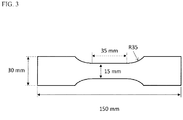
- a fatigue test specimen having a form and a size shown in FIG. 3 and a tensile direction in the rolling direction is taken out, and a fatigue strength thereof is measured after repetitions of 10 7 times under conditions of pulsating tension loading, a stress ratio of 0.1, and a frequency of 20 Hz.
- the tensile strength TS is stable at about 620 MPa while the fatigue strength largely varies in accordance with the experimental conditions.
- the fatigue strength means a maximum stress of an amplitude stress applied to the test piece.
- ODF Crystalstalline Orientation Distribution Function
- the inventors consider the mechanism as follows, although it has not been cleared sufficiently.
- ⁇ -fiber which is known to be hard to be recrystallized.
- non-recrystallized texture of the finish-annealed sheet belongs mainly to ⁇ -fiber. That it, when the recrystallization ratio is the same, the small value of C ⁇ D corresponds to large orientation dispersion in the non-recrystallized texture of the finish-annealed sheet and small ⁇ 100 ⁇ 011> orientation, which is considered to contribute to the increase in fatigue strength.
- the non-recrystallized texture with the large orientation dispersion hardly causes the deformation along a particular crystal face and provides a high fatigue strength stably.
- ⁇ 100 ⁇ 011> orientation is known as a rolling stable orientation and has a property that the orientation hardly changes during cold rolling. Accordingly, in order to increase the orientation dispersion in the ⁇ -fiber, it is considered effective to decrease accumulation degree into ⁇ 100 ⁇ 011> orientation as a main orientation in the stage of the hot-rolled sheet (before the cold rolling) and promote crystal rotation in the subsequent cold rolling.
- the inventors have performed various experiments to study a hot-rolling condition for decreasing the accumulation degree into ⁇ 100 ⁇ 011> orientation in the hot-rolled sheet, i.e., decreasing the value of C ⁇ D.
- FIG. 2 it has been found effective to increase the rolling reduction of the final pass in the finish rolling of the hot rolling and also lower the coiling temperature after the hot rolling, concretely, to increase the rolling reduction of the final pass to not less than 10% and decrease the coiling temperature to not higher than 620°C.
- the dislocation density and stored energy of the hot-rolled sheet increase and thereby promote recrystallization in the hot-band annealing in all orientations to thus randomize the texture, as a result of which the orientation dispersion of the hot-band annealed sheet is considered to be promoted.
- the value of C is necessary to be not less than 2.0, preferably not less than 3.0.
- the invention is developed based on the above new knowledge.
- the measurements of C and D are not limited to the above methods and may be performed by using another well-known method, for example, a texture measurement through EBSP.
- C is an element forming a carbide and deteriorating an iron loss of a product sheet.
- the content exceeding 0.0050 mass% causes the above adverse effect to be remarkable. Therefore, C is limited to not more than 0.0050 mass% from a viewpoint of suppressing magnetic aging of the product sheet, preferably to not more than 0.0030 mass%.
- Si has an effect of increasing a specific resistance of steel and reducing an iron loss. It also has an effect of increasing a strength of steel by solid-solution strengthening. The above effects become remarkable as Si content is high, and hence, Si is contained by not less than 3.2 mass% according to the invention. However, Si content exceeding 5.0 mass% causes the rolling to be difficult, so that the upper limit of Si is 5.0 mass%. Preferably, Si content falls within the range of 3.5 to 4.5 mass%.
- Mn has an effect of increasing the specific resistance of steel and reducing the iron loss, like Si, and preferably contained by not less than 0.1 mass%.
- Mn content exceeds 2.0 mass%, the iron loss is rather deteriorated by the precipitation of carbonitride, and therefore, Mn content is limited to not more than 2.0 mass%. Therefore, Mn is preferably added by 0.1 to 2.0 mass%, more preferably 0.3 to 1.0 mass%.
- P is an element having a high solid-solution strengthening ability and used to adjust steel hardness.
- the P content exceeding 0.02 mass% causes the rolling to be difficult due to embrittlement of steel, and hence, the upper limit of P is 0.02 mass%, preferably not more than 0.01 mass%.
- S is a harmful element forming fine sulfide and blocking grain growth to thereby increase the iron loss.
- the upper limit is 0.0050 mass%, and preferably not more than 0.0030 mass%.
- Al has an effect of increasing the specific resistance of steel and reducing the iron loss, like Si. It also has an effect of increasing the strength of steel by solid-solution strengthening.
- the above effects are small when Al content is less than 0.5 mass%, while the rolling becomes difficult when it exceeds 2.0 mass%. Accordingly, the Al content is set to fall within the range of 0.5 to 2.0 mass%, preferably within the range of 0.7 to 1.3 mass%.
- N is a harmful element that increases fine nitride to block grain growth and increase the iron loss.
- the upper limit is 0.0050 mass%, preferably not more than 0.0030 mass%.
- Ti is a harmful element that is precipitated as fine carbonitride to block grain growth and increase the iron loss.
- the upper limit is 0.0030 mass%, preferably not more than 0.0020 mass%.
- Nb is a harmful element that is precipitated as fine carbonitride to block grain growth and increase the iron loss, like Ti.
- the upper limit is 0.0010 mass%, preferably not more than 0.0005 mass%.
- V is also a harmful element that is precipitated as fine carbonitride to block grain growth and increase the iron loss, like Ti.
- the upper limit is 0.0050 mass%, preferably not more than 0.0030 mass%.
- O is a harmful element forming oxide-based inclusions to block grain growth and increase the iron loss.
- the upper limit is 0.0050 mass%, preferably more than 0.0030 mass%.
- Si + Al not less than 4.0 mass%
- the non-oriented electrical steel sheet according to the invention is necessary to contain Si and Al such that the total content adds up to not less than 4.0 mass%, in addition to satisfying the above chemical composition.
- the total content of Si and Al is preferably not less than 4.4 mass%.
- the upper limit is preferably about 6.0 mass%.
- the raw steel material used in the invention may contain the following elements properly in addition to the above ingredients.
- Sn and Sb have an effect of improving the recrystallized texture and reducing the iron loss. In order to obtain the above effect, it is necessary to add each element by not less than 0.005 mass%. On the other hand, when each ingredient is added by more than 0.20 mass%, the above effect is saturated. Therefore, Sn and Sb are each preferably added within the range of 0.005 to 0.20 mass%, more preferably, within the range of 0.01 to 0.10 mass%.
- Ca, Mg and REM form stable sulfide and have an effect of decreasing fine sulfide and improving grain growth and the iron loss.
- Ca, Mg and REM are each preferable to be added within the range of 0.0005 to 0.010 mass%, more preferably within the range of 0.001 to 0.005 mass%.
- the raw steel material used in the invention may contain properly the following elements in addition to the aforementioned elements.
- these elements are relatively high in the raw material cost, and it is desirable to suppress the addition amount thereof to the minimum necessary.
- Cr has an effect of increasing the specific resistance of steel and thus reducing the iron loss, like Si.
- Cr is small in the solid-solution strengthening ability as compared to Si and Al, and accordingly it is preferable to be added when it is desired to decrease the iron loss without deteriorating the rolling property.
- the addition amount is less than 0.01 mass%, the above effect cannot be obtained sufficiently, while when it exceeds 5 mass%, the effect of improving the iron loss is saturated. Therefore, Cr is preferable to be added by 0.01 to 5 mass%.
- Cu has an effect of increasing the specific resistance of steel and thus reducing the iron loss, like Si.
- Cu is small in the solid-solution strengthening ability as compared to Si and Al, and accordingly it is preferable to be added when it is desired to reduce the iron loss without deteriorating the rolling property.
- the addition amount is less than 0.01 mass, the above effect cannot be obtained sufficiently, while when it exceeds 5 mass%, the effect of improving the iron loss is saturated. Therefore, Cu is preferable to be added within the range of 0.01 to 5 mass%.
- Ni is an element being large in the effect of increasing the strength of steel by solid-solution strengthening.
- the addition amount is less than 0.01 mass%, the above effect cannot be obtained sufficiently, while when it exceeds 5 mass%, the raw material cost is largely increased. Therefore, Ni is preferable to be added by 0.01 to 5 mass%.
- Mo has an effect of coarsening carbide and thus reducing the iron loss.
- the addition amount is less than 0.0005 mass%, the above effect cannot be obtained sufficiently, while when it exceeds 0.1 mass%, the effect of improving the iron loss is saturated. Therefore, Mo is preferable to be added by 0.01 to 5 mass%.
- W has an effect of coarsening carbide and reducing the iron loss, like Mo.
- the addition amount is less than 0.001 mass%, the above effect cannot be obtained sufficiently, while when it exceeds 0.1 mass%, the effect of improving the iron loss is saturated. Therefore, W is preferable to be added by 0.01 to 0.1 mass%.
- Co is an element increasing the magnetic moment of Fe alloy and has an effect of increasing a magnetic flux density and reducing the iron loss.
- the addition amount is less than 0.01 mass%, the above effects cannot be obtained sufficiently, while when it exceeds 5 mass%, the raw material cost is largely increased. Therefore, Co is preferable to be added by 0.01 to 5 mass%.
- the above effect is obtained by the addition of not less than 0.001 mass%.
- B is a grain boundary segregation element and has an effect of improving the texture and thus reducing the iron loss, like As. Since B is highly effective in suppressing the grain boundary migration, an excessive addition of B may rather block the grain growth in the stress-relief annealing to cause the increase in the iron loss. When the addition amount is less than 0.0001 mass%, the above effect cannot be obtained sufficiently, while when it exceeds 0.005 mass%, the adverse effect of suppressing the grain boundary migration increases. Therefore, B is preferable to be added by 0.0001 to 0.005 mass%.
- the remainder other than the above elements is Fe and inevitable impurities.
- the non-oriented electrical steel sheet according to the invention can be produced by the usual production process of subjecting a raw steel material (slab) having a chemical composition in accordance with the invention to a hot rolling, a hot-band annealing, a single cold rolling or two or more cold rollings with an intermediate annealing between each cold rolling to form a cold-rolled sheet with a final sheet thickness, and a finish annealing.
- the raw steel material (slab) be produced by melting a steel having a chemical composition adapted to the invention by a usual refining process, where a molten steel obtained in a converter, an electric furnace or the like is subjected to a secondary refining in a vacuum degassing device or the like, to adjust to a given chemical composition, and then conducting a continuous casting method or an ingot making ⁇ blooming method.
- the slab is then reheated to a given temperature in a gas furnace or the like and subjected to a hot rolling comprised of a rough rolling and a finish rolling to form a hot-rolled sheet.
- the temperature for reheating the slab is preferable to be not higher than 1150°C to suppress re-solid solution of AlN, MnS or the like and preventing subsequent fine precipitation. More preferably, it is within the range of 1000 to 1130°C.
- the reheating step of the slab may be omitted when the hot rolling temperature can be ensured.
- a thin slab caster constituted by integrating a continuous casting machine with a rolling machine can be used, where the hot rolling process may be omitted.
- the hot rolling following the reheating of the slab is the most important step in the invention.
- the final pass of the finish rolling is performed at a high rolling reduction and a coiling temperature of a coil after the hot rolling is lowered.
- the rolling reduction of the final pass be not less than 10% and the coiling temperature be not higher than 620°C.
- the rolling reduction of the final pass is less than 10% or the coiling temperature is higher than 620°C, the dislocation density in the hot-rolled sheet is decreased and the texture after the hot-band annealing is not sufficiently randomized.
- the rolling reduction of the final pass be not less than 14% and the coiling temperature be not higher than 590°C.
- the hot-rolled sheet is subjected to a hot-band annealing, which is preferably conducted under soaking conditions of 700 to 1100°C for 1 to 300 seconds.
- a hot-band annealing which is preferably conducted under soaking conditions of 700 to 1100°C for 1 to 300 seconds.
- the hot-band annealing is preferably conducted at 800 to 1000°C for 5 to 100 seconds.
- the hot-rolled sheet after the hot-band annealing is subjected to a single cold rolling or two or more cold rollings with an intermediate annealing between each rolling to form a cold-rolled sheet with a final sheet thickness.
- the cold rolling is also an important step in the invention.
- the steel sheet temperature at the exit side of the first pass is lower than 80°C or when the rolling reduction at the first pass is less than 30%, the crystal rotation from ⁇ 100 ⁇ 011> to other orientations becomes insufficient. That is, as the steel sheet temperature is higher or the rolling reduction is higher, a plurality of slip systems are more active, and thus the crystal rotation to other orientations is easily caused and accumulation into ⁇ 100 ⁇ 011> is suppressed. It is preferable that steel sheet temperature at the exit side of the first pass be not lower than 100°C and the rolling reduction at the first pass be not less than 40%. Moreover, the steel sheet temperature at the exit side of the first pass can be adjusted by raising the steel sheet temperature before the rolling or raising the temperature of a coolant or decreasing the amount of a coolant.
- the cold-rolled sheet which has been cold rolled to have the final thickness, is subjected to a finish annealing.
- the finish annealing is also an important step in the invention. In order to reduce the iron loss by decreasing the dislocation density and also allow the non-recrystallized structure to be left to secure the strength, that is, to allow the recrystallization ratio to be less than 100%, it is important to control a soaking temperature in the finish annealing within the range of 600 to 800°C.
- the soaking temperature is lower than 600°C, the dislocation density increases and the iron loss becomes too high, while when it exceeds 800°C, the recrystallization is promoted to make it difficult to stably retain the non-recrystallized texture and thus to make it difficult to ensure the high strength.
- the preferable soaking temperature is within the range of 680 to 760°C.
- the lower limit of the recrystallization ratio of the steel sheet after the finish annealing is not particularly defined, but an excessively low recrystallization ratio causes the iron loss to increase, so that it is preferably within the range of 30 to 95%.
- the recrystallization ratio can be easily measured by polishing a sectional face of the steel sheet parallel to the rolling direction, etching the face to reveal the microstructure and comparing an area ratio occupied with the recrystallized grains to an area ratio of the non-recrystallized zone.
- the steel sheet after the finish annealing be coated with an insulation coating, if necessary.
- the insulation coating may use any of known organic, inorganic and organic/inorganic mixed coatings in accordance with the purpose.
- the present invention achieves high strength by using a high alloy steel as a raw material and allowing the non-recrystallized structure to remain, and it is not necessary to conduct skin-pass rolling for considerably increasing the iron loss for the higher strength. Moreover, the presence or absence of the skin-pass rolling can be determined by texture observation with an optical microscope or EBSP.
- the thus-obtained non-oriented electrical steel sheet according to the invention has such excellent properties as low iron loss and high strength, and accordingly is suitable as a raw material of a rotor core.
- an excellent motor efficiency may not be obtained due to the high iron loss.
- This method is suitable to be used in PM motor being particularly low in the iron loss ratio of the rotor core.
- a steel having a chemical composition shown in Table 1 and the remainder being Fe and inevitable impurities is melted by a usual refining process and formed into a slab by a continuous casting method.
- the slab is heated in a gas furnace at a temperature of 1100°C for 30 minutes and subjected to a hot-rolling comprised of a rough rolling and a finish rolling to form a hot-rolled sheet having a sheet thickness of 1.8 mm.
- the hot-rolled sheet is subjected to a hot-band annealing at 930°C for 30 seconds, pickled and cold-rolled to form a cold-rolled sheet with a final sheet thickness of 0.3 mm.
- the cold-rolled sheet is subjected to a finish annealing to form a product sheet.
- Table 2 The conditions of the hot rolling, cold rolling and finish annealing are summarized and shown in Table 2.
- samples are taken out from the thus-obtained product sheet and subjected to a tensile test and a fatigue test.
- a tensile test a JIS No. 5 tensile test specimen is taken out from the sample so as to have a tensile direction in the rolling direction to measure a tensile strength TS according to JIS Z2241.
- a fatigue test specimen having a shape and a size shown in FIG. 3 is taken out from the above sample so as to have a tensile direction in the rolling direction to measure a fatigue strength after repetitions of 10 7 times under condition of a pulsating tension loading, a stress ratio of 0. 1 and a frequency of 20 Hz.
- Test pieces with a width of 30 mm and a length of 280 mm are taken out from L-direction (rolling direction) and C-direction (direction perpendicular to the rolling direction) of the above sample to measure an iron loss W 10/400 according to JIS C2550-1. Further, the iron loss W 10/400 after stress-relief annealing (SRA) in N 2 atmosphere at 800°C for 2 hours is measured.
- SRA stress-relief annealing
Landscapes
- Chemical & Material Sciences (AREA)
- Engineering & Computer Science (AREA)
- Metallurgy (AREA)
- Organic Chemistry (AREA)
- Mechanical Engineering (AREA)
- Materials Engineering (AREA)
- Physics & Mathematics (AREA)
- Crystallography & Structural Chemistry (AREA)
- Thermal Sciences (AREA)
- Electromagnetism (AREA)
- Manufacturing & Machinery (AREA)
- Dispersion Chemistry (AREA)
- Power Engineering (AREA)
- Health & Medical Sciences (AREA)
- Child & Adolescent Psychology (AREA)
- Soft Magnetic Materials (AREA)
- Manufacturing Of Steel Electrode Plates (AREA)
Abstract
Description
- This invention relates to a non-oriented electrical steel sheet and a method for producing the same, and more particularly to a non-oriented electrical steel sheet having a high strength and a low iron loss and a method for producing the same.
- In recent years, development of motor drive systems has made it possible to control the frequency of the drive power supply, and there has been an increase in motors that operate at variable speeds or rotate at high speeds above commercial frequencies. A motor core is formed of a stator core fixed in a motor case and a rotor core rotating at a high speed, and centrifugal force is generated in the rotating rotor core. The magnitude of the centrifugal force is proportional to radius of rotation and proportional to the square of the rotating speed. Accordingly, a steel sheet as a raw material of a middle- and large-size rotor cores rotating at a high speed is demanded to have a high strength.
- IPM motors are used in drive motors for electric vehicles, hybrid vehicles, etc., have a slit in the outer circumference of the rotor, and a magnet is embedded in the slit, where stress is concentrated in a narrow bridge portion supporting the magnet. Therefore, a steel sheet as a raw material of the rotor core, even a relatively small-size motor, is demanded to have a high strength.
- In the motor rotating at a high speed, eddy current is generated by a high-frequency magnetic flux, which causes a decrease in motor efficiency and causes heat generation. Since a large amount of heat generation in the rotor causes demagnetization of the magnet, the raw material of the rotor core is demanded to be low in the iron loss even at a high frequency zone. Thus, a steel sheet being excellent in the balance between high strength and low iron loss is required as the raw material used for the rotor core.
- A method for attaining high strength includes, for example, a method of adding a large amount of a solid-solution strengthening element such as Si, Al and the like to iron and thus forming a high alloy steel. This method can attain low iron loss and high strength at the same time and is preferably used. There is another method of using precipitation strengthening to achieve high strength by forming a high alloy steel, but the method has a problem that the precipitated second phase grains considerably block the grain growth in finish annealing or stress-relief annealing. Moreover, as a method for attaining high strength other than by forming high alloy steel, there is widely used a method of increasing strength by making crystal grains finer. This method comprises forming a motor core using a high-strength material and subjecting only the stator core to stress-relief annealing so as to cause grain growth, resulting in an advantage that the stator core has a low iron loss while the rotor core has a high strength.
- Under such a situation, there are proposed other methods for increasing the strength of a non-oriented electrical steel sheet. For example, Patent Literatures 1 and 2 propose a method of attaining high strength by using non-recrystallized texture. Also, Patent Literature 3 proposes a method of controlling the configuration of non-recrystallized texture to suppress a variation in tensile strength and fatigue strength.
-
- Patent Literature 1:
JP-A-2006-169611 - Patent Literature 2:
JP-A-2005-113185 - Patent Literature 3:
JP-A-2010-090474 - The inventors have produced a non-oriented electrical steel sheet using a high-alloy steel as a raw material by applying the method disclosed in Patent Literatures 1 and 2, and as result, found that these methods have a problem that fatigue strength is largely varied. Although the method disclosed in Patent Literature 3 can suppress variations in tensile strength and fatigue strength, the Al and Mn contents are limited to a relatively low amount, causing a problem of low specific resistance and high iron loss at a high-frequency.
- The invention is made in consideration of the above problems inherent to the conventional methods, and an object thereof is to provide a non-oriented electrical steel sheet having a high strength (high tensile strength and high fatigue strength) and a low iron loss by using a high-alloy steel having a high Si and Al contents as a raw material and propose an advantageous method for producing the same.
- In order to solve the problems, the inventors have made various studies, focusing on a combination technique of increasing the strength by using a high alloy steel material and increasing the strength by using a non-recrystallized texture. As a result, they have found that, in order to stably produce a non-oriented electrical steel sheet having a high strength (high tensile strength and high fatigue strength) and a low iron loss using the combination technique, it is effective to adjust the texture of a product sheet, and thus the invention has been accomplished.
- The invention based on the above knowledge is a non-oriented electrical steel sheet having a chemical composition comprising C: not more than 0.0050 mass%, Si: 3.2 to 5.0 mass%, Mn: not more than 2.0 mass%, P: not more than 0.02 mass%, S: not more than 0.0050 mass%, Al: 0.5 to 2.0 mass%, N: not more than 0.0050 mass%, Ti: not more than 0.0030 mass%, Nb: not more than 0.0010 mass%, V: not more than 0.0050 mass%, O: not more than 0.0050 mass%, provided that Si + Al ≥ 4.0 mass%, and the remainder being Fe and inevitable impurities, in which
- a recrystallization ratio is less than 100% as an area ratio,
- a strength C is not less than 2.0, and
- a strength difference C-D is not more than 2.0, where C is a strength at Φ= 0° and ϕ1= 0° and D is a strength at Φ= 20° and ϕ1= 0° in a section of ϕ2= 45° of ODF obtained in a central layer of a sheet thickness.
- The non-oriented electrical steel sheet according to the invention is characterized by containing one or two selected from Sn and Sb by 0.005 to 0.20 mass% each, in addition to the above chemical composition.
- The non-oriented electrical steel sheet according to the invention is characterized by containing one or more selected from Ca, Mg and REM by 0.0005 to 0.010 mass% each, in addition to the above chemical composition.
- The non-oriented electrical steel sheet according to the invention is characterized by containing at least one selected from Cr: 0.01 to 5 mass%, Cu: 0.01 to 5 mass%, Ni: 0.01 to 5 mass%, Mo: 0.0005 to 0.1 mass%, W: 0.001 to 0.1 mass%, Co: 0.01 to 5 mass%, As: 0.001 to 0.05 mass% and B: 0.0001 to 0.005 mass%, in addition to the above chemical composition.
- Moreover, the invention proposes a method for producing a non-oriented electrical steel sheet comprising subjecting a steel slab having a chemical composition described in any one of the above items to a hot rolling, a hot-band annealing, a single cold rolling or two or more cold rollings with an intermediate annealing between each rolling to form a cold-rolled sheet with a final sheet thickness, and a finish annealing, characterized in that
- a rolling reduction of a final finish rolling pass in the hot rolling is not less than 10%,
- a coiling temperature after the hot rolling is not higher than 620°C, and a soaking temperature in the finish annealing is 600 to 800°C to achieve such properties that
- a recrystallization ratio is less than 100% as an area ratio,
- the strength C is not less than 2.0 and
- a strength difference C-D is not more than 2.0, where C is a strength at Φ= 0° and ϕ1= 0° and D is a strength at Φ= 20° and ϕ1= 0° in a section of ϕ2= 45° of ODF obtained in a central layer of a sheet thickness.
- The method for producing a non-oriented electrical steel sheet according to the invention is characterized in that a temperature of the steel sheet at an exit side of a first pass in a final cold rolling of the cold rolling is not lower than 80°C.
- The method for producing a non-oriented electrical steel sheet according to the invention is characterized in that a rolling reduction of the first pass in the final cold rolling of the cold rolling is not less than 30%. Advantageous Effects of Invention
- The invention can stably provide non-oriented electrical steel sheets having a high strength (high tensile strength, high fatigue strength) and a low iron loss, which can favorably be used as a raw material of a motor core in a motor rotating at a high speed, a driving motor for electric vehicles or hybrid vehicles and so on.
-
-
FIG. 1 is a graph showing an influence of C ― D upon fatigue strength, where C is a strength at Φ= 0° and ϕ1= 0° and D is a strength at Φ= 20° and ϕ1= 0° in a section of ϕ2= 45° of ODF obtained in a central layer of a sheet thickness. -
FIG. 2 is a graph showing an influence of a rolling reduction of a final finish rolling pass in hot rolling and a coiling temperature upon C ― D, where C is a strength at Φ= 0° and ϕ1= 0° and D is a strength at Φ= 20° and (ϕ1= 0° in a section of ϕ2= 45° of ODF obtained in a central layer of a sheet thickness. -
FIG. 3 is a schematic view illustrating a test specimen used in a fatigue test. - There will be described an experiment that has led to the development of the invention.
- A steel having a chemical composition comprising C: 0.0019 mass%, Si: 3.52 mass%, Mn: 0.41 mass%, P: 0.01 mass%, S: 0.0018 mass%, Al: 0.91 mass%, N: 0.0017 mass%, Ti: 0.0008 mass%, Nb: 0.0001 mass%, V: 0.0012 mass%, O: 0.0025 mass% and the remainder being Fe and inevitable impurities is melted by a common refining process and shaped into a raw steel material (slab) by a continuous casting method. The slab is then heated at a temperature of 1100°C in a gas furnace for 30 minutes and subjected to a hot rolling comprised of a rough rolling and a finish rolling to form a hot-rolled sheet having a sheet thickness of 1.8 mm, which is wound up into a coil. In this case, the thickness of a sheet bar is 40 mm, and an entry side temperature FET in the finish rolling is 980°C, and an exit side temperature FDT (rolling end temperature) is 820°C, and a pass schedule in the finish rolling and a coiling temperature CT are changed variously.
- Then, a test specimen is taken out from the hot-rolled sheet, subjected to a heat treatment simulating a hot-band annealing at 980°C for 30 seconds in a laboratory, pickled and cold rolled to form a cold-rolled sheet having a final sheet thickness of 0.30 mm. The cold-rolled sheet is then subjected to a finish annealing at 740°C for 20 seconds to form a finish-annealed sheet having a recrystallization ratio of 70% as an area ratio.
- A test specimen is taken out from the thus-obtained finish-annealed sheet and subjected to the following tensile test and fatigue test.
- In the tensile test, a JIS No. 5 tensile test piece with a tensile direction in the rolling direction is taken out from the test specimen, and a tensile strength TS thereof is measured according to JIS Z2241. In the fatigue test, a fatigue test specimen having a form and a size shown in
FIG. 3 and a tensile direction in the rolling direction is taken out, and a fatigue strength thereof is measured after repetitions of 107 times under conditions of pulsating tension loading, a stress ratio of 0.1, and a frequency of 20 Hz. As a result, it has been seen that the tensile strength TS is stable at about 620 MPa while the fatigue strength largely varies in accordance with the experimental conditions. In this regard, the fatigue strength means a maximum stress of an amplitude stress applied to the test piece. - Various studies has been made to investigate the cause for the variation of the fatigue strength, and as a result, it has been clarified that the fatigue strength is significantly affected by the texture of the steel sheet, concretely, the material having a low fatigue strength is high in the strength in the vicinity of {100}<011> orientation, that is, ( Φ, ϕ1, ϕ2) = (0°, 0°, 45°) as an Euler angle while the material having a high fatigue strength is low in {100}<011> orientation and high in the strength in the vicinity of {114}<011> orientation, that is, ( Φ, ϕ1, ϕ2) = (20°, 0°, 45°) as an Euler angle.
-
FIG. 1 shows a relation between C ― D and a fatigue strength, where C is a strength at Φ= 0° and ϕ1= 0° and D is a strength at Φ= 20° and ϕ1= 0° in a section of ϕ2= 45° of ODF (Crystalline Orientation Distribution Function) obtained in a central layer of a sheet thickness. As seen fromFIG. 1 , the fatigue strength rapidly increases when the value of C ― D is not more than 2.0, while it is almost saturated when the value of C ― D is not more than 1.5. In order to increase the fatigue strength, therefore, C -D is necessary to be not more than 2.0, and is more preferably not more than 1.5. - The inventors consider the mechanism as follows, although it has not been cleared sufficiently. In the section of ϕ2 = 45°, the orientation group in the vicinity of ϕ1 = 0° and Φ= 0 to 50° corresponds to so-called α-fiber, which is known to be hard to be recrystallized. It is considered that non-recrystallized texture of the finish-annealed sheet belongs mainly to α-fiber. That it, when the recrystallization ratio is the same, the small value of C ― D corresponds to large orientation dispersion in the non-recrystallized texture of the finish-annealed sheet and small {100}<011> orientation, which is considered to contribute to the increase in fatigue strength. In other words, it is considered that the non-recrystallized texture with the large orientation dispersion hardly causes the deformation along a particular crystal face and provides a high fatigue strength stably.
- Also, {100}<011> orientation is known as a rolling stable orientation and has a property that the orientation hardly changes during cold rolling. Accordingly, in order to increase the orientation dispersion in the α-fiber, it is considered effective to decrease accumulation degree into {100}<011> orientation as a main orientation in the stage of the hot-rolled sheet (before the cold rolling) and promote crystal rotation in the subsequent cold rolling.
- The inventors have performed various experiments to study a hot-rolling condition for decreasing the accumulation degree into {100}<011> orientation in the hot-rolled sheet, i.e., decreasing the value of C ― D. As a result, as shown in
FIG. 2 , it has been found effective to increase the rolling reduction of the final pass in the finish rolling of the hot rolling and also lower the coiling temperature after the hot rolling, concretely, to increase the rolling reduction of the final pass to not less than 10% and decrease the coiling temperature to not higher than 620°C. Under such a condition, the dislocation density and stored energy of the hot-rolled sheet increase and thereby promote recrystallization in the hot-band annealing in all orientations to thus randomize the texture, as a result of which the orientation dispersion of the hot-band annealed sheet is considered to be promoted. - As mentioned above, the strength C at Φ= 0° and ϕ1= 0° in the section of ϕ2 = 45° of ODF is related to the non-recrystallized texture and decreases as the recrystallization progresses. In the steel sheet according to the invention, where the non-recrystallized texture remains, that is, the recrystallization ratio is less than 100% as an area ratio, the value of C is necessary to be not less than 2.0, preferably not less than 3.0.
- The invention is developed based on the above new knowledge.
- The strength C at the orientation of ( Φ, ϕ1, ϕ2) = (0°, 0°, 45°) and the strength D at the orientation of ( Φ, ϕ1, ϕ2) = (20°, 0°, 45°) are determined by calculating ODF by a series expanding method or an ADC method using a plurality of pole figures (preferably not less than 3) selected from {110}, {200}, {211}, {310} pole figures and so on obtained by X-ray diffraction of a center layer of sheet thickness polished to 1/2 of the steel sheet thickness. In this regard, the measurements of C and D are not limited to the above methods and may be performed by using another well-known method, for example, a texture measurement through EBSP.
- The reason of limiting the chemical composition of the raw steel material used in the invention will be described below.
- C is an element forming a carbide and deteriorating an iron loss of a product sheet. The content exceeding 0.0050 mass% causes the above adverse effect to be remarkable. Therefore, C is limited to not more than 0.0050 mass% from a viewpoint of suppressing magnetic aging of the product sheet, preferably to not more than 0.0030 mass%.
- Si has an effect of increasing a specific resistance of steel and reducing an iron loss. It also has an effect of increasing a strength of steel by solid-solution strengthening. The above effects become remarkable as Si content is high, and hence, Si is contained by not less than 3.2 mass% according to the invention. However, Si content exceeding 5.0 mass% causes the rolling to be difficult, so that the upper limit of Si is 5.0 mass%. Preferably, Si content falls within the range of 3.5 to 4.5 mass%.
- Mn has an effect of increasing the specific resistance of steel and reducing the iron loss, like Si, and preferably contained by not less than 0.1 mass%. However, when Mn content exceeds 2.0 mass%, the iron loss is rather deteriorated by the precipitation of carbonitride, and therefore, Mn content is limited to not more than 2.0 mass%. Therefore, Mn is preferably added by 0.1 to 2.0 mass%, more preferably 0.3 to 1.0 mass%.
- P is an element having a high solid-solution strengthening ability and used to adjust steel hardness. In the high-alloy steel as in the invention, the P content exceeding 0.02 mass% causes the rolling to be difficult due to embrittlement of steel, and hence, the upper limit of P is 0.02 mass%, preferably not more than 0.01 mass%.
- S is a harmful element forming fine sulfide and blocking grain growth to thereby increase the iron loss. In particularly, when S content exceeds 0.0050 mass%, the above adverse effect is remarkable. Hence, the upper limit is 0.0050 mass%, and preferably not more than 0.0030 mass%.
- Al has an effect of increasing the specific resistance of steel and reducing the iron loss, like Si. It also has an effect of increasing the strength of steel by solid-solution strengthening. However, the above effects are small when Al content is less than 0.5 mass%, while the rolling becomes difficult when it exceeds 2.0 mass%. Accordingly, the Al content is set to fall within the range of 0.5 to 2.0 mass%, preferably within the range of 0.7 to 1.3 mass%.
- N is a harmful element that increases fine nitride to block grain growth and increase the iron loss. In particular, when N content exceeds 0.0050 mass, the above adverse effect becomes remarkable. Hence, the upper limit is 0.0050 mass%, preferably not more than 0.0030 mass%.
- Ti is a harmful element that is precipitated as fine carbonitride to block grain growth and increase the iron loss. In particular, when Ti content exceeds 0.0030 mass%, the above adverse effect becomes remarkable. Hence, the upper limit is 0.0030 mass%, preferably not more than 0.0020 mass%.
- Nb is a harmful element that is precipitated as fine carbonitride to block grain growth and increase the iron loss, like Ti. In particular, when Nb content exceeds 0.0010 mass%, the above adverse effect becomes remarkable. Therefore, the upper limit is 0.0010 mass%, preferably not more than 0.0005 mass%.
- V is also a harmful element that is precipitated as fine carbonitride to block grain growth and increase the iron loss, like Ti. In particular, when V content exceeds 0.0050 mass%, the above adverse effect becomes remarkable. Hence, the upper limit is 0.0050 mass%, preferably not more than 0.0030 mass%.
- O is a harmful element forming oxide-based inclusions to block grain growth and increase the iron loss. In particularly, when O content exceeds 0.0050 mass%, the above adverse effect becomes remarkable. Hence, the upper limit is 0.0050 mass%, preferably more than 0.0030 mass%.
- The non-oriented electrical steel sheet according to the invention is necessary to contain Si and Al such that the total content adds up to not less than 4.0 mass%, in addition to satisfying the above chemical composition. When the total content of Si and Al is less than 4.0 mass%, it is difficult to stably secure a high strength and high fatigue strength. The total content of Si and Al is preferably not less than 4.4 mass%. However, when the total content of Si and Al exceeds 6.0 mass%, steel is hardened and the rolling becomes difficult. Hence, the upper limit is preferably about 6.0 mass%.
- The raw steel material used in the invention may contain the following elements properly in addition to the above ingredients.
- Sn and Sb have an effect of improving the recrystallized texture and reducing the iron loss. In order to obtain the above effect, it is necessary to add each element by not less than 0.005 mass%. On the other hand, when each ingredient is added by more than 0.20 mass%, the above effect is saturated. Therefore, Sn and Sb are each preferably added within the range of 0.005 to 0.20 mass%, more preferably, within the range of 0.01 to 0.10 mass%.
- Ca, Mg and REM form stable sulfide and have an effect of decreasing fine sulfide and improving grain growth and the iron loss. In order to obtain the above effect, it is necessary to add each element by not less than 0.0005 mass%. On the other hand, when each element is added by more than 0.010 mass%, the iron loss is rather deteriorated. Therefore, Ca, Mg and REM are each preferable to be added within the range of 0.0005 to 0.010 mass%, more preferably within the range of 0.001 to 0.005 mass%.
- The raw steel material used in the invention may contain properly the following elements in addition to the aforementioned elements. However, these elements are relatively high in the raw material cost, and it is desirable to suppress the addition amount thereof to the minimum necessary.
- Cr has an effect of increasing the specific resistance of steel and thus reducing the iron loss, like Si. However, Cr is small in the solid-solution strengthening ability as compared to Si and Al, and accordingly it is preferable to be added when it is desired to decrease the iron loss without deteriorating the rolling property. When the addition amount is less than 0.01 mass%, the above effect cannot be obtained sufficiently, while when it exceeds 5 mass%, the effect of improving the iron loss is saturated. Therefore, Cr is preferable to be added by 0.01 to 5 mass%.
- Cu has an effect of increasing the specific resistance of steel and thus reducing the iron loss, like Si. However, Cu is small in the solid-solution strengthening ability as compared to Si and Al, and accordingly it is preferable to be added when it is desired to reduce the iron loss without deteriorating the rolling property. When the addition amount is less than 0.01 mass, the above effect cannot be obtained sufficiently, while when it exceeds 5 mass%, the effect of improving the iron loss is saturated. Therefore, Cu is preferable to be added within the range of 0.01 to 5 mass%.
- Ni is an element being large in the effect of increasing the strength of steel by solid-solution strengthening. When the addition amount is less than 0.01 mass%, the above effect cannot be obtained sufficiently, while when it exceeds 5 mass%, the raw material cost is largely increased. Therefore, Ni is preferable to be added by 0.01 to 5 mass%.
- Mo has an effect of coarsening carbide and thus reducing the iron loss. However, when the addition amount is less than 0.0005 mass%, the above effect cannot be obtained sufficiently, while when it exceeds 0.1 mass%, the effect of improving the iron loss is saturated. Therefore, Mo is preferable to be added by 0.01 to 5 mass%.
- W has an effect of coarsening carbide and reducing the iron loss, like Mo. However, when the addition amount is less than 0.001 mass%, the above effect cannot be obtained sufficiently, while when it exceeds 0.1 mass%, the effect of improving the iron loss is saturated. Therefore, W is preferable to be added by 0.01 to 0.1 mass%.
- Co is an element increasing the magnetic moment of Fe alloy and has an effect of increasing a magnetic flux density and reducing the iron loss. However, when the addition amount is less than 0.01 mass%, the above effects cannot be obtained sufficiently, while when it exceeds 5 mass%, the raw material cost is largely increased. Therefore, Co is preferable to be added by 0.01 to 5 mass%.
- As is a grain boundary segregation element and has an effect of improving the texture and thus reducing the iron loss. The above effect is obtained by the addition of not less than 0.001 mass%. However, As is an element causing grain boundary embrittlement, and this adverse effect becomes particularly remarkable when it is added by more than 0.05 mass%. Therefore, As is preferable to be added within the range of 0.001 to 0.05 mass%.
- B is a grain boundary segregation element and has an effect of improving the texture and thus reducing the iron loss, like As. Since B is highly effective in suppressing the grain boundary migration, an excessive addition of B may rather block the grain growth in the stress-relief annealing to cause the increase in the iron loss. When the addition amount is less than 0.0001 mass%, the above effect cannot be obtained sufficiently, while when it exceeds 0.005 mass%, the adverse effect of suppressing the grain boundary migration increases. Therefore, B is preferable to be added by 0.0001 to 0.005 mass%.
- In the non-oriented electrical steel sheet according to the invention, the remainder other than the above elements is Fe and inevitable impurities.
- There will be described a method for producing a non-oriented electrical steel sheet according to the invention.
- The non-oriented electrical steel sheet according to the invention can be produced by the usual production process of
subjecting a raw steel material (slab) having a chemical composition in accordance with the invention to a hot rolling, a hot-band annealing, a single cold rolling or two or more cold rollings with an intermediate annealing between each cold rolling to form a cold-rolled sheet with a final sheet thickness, and a finish annealing. - It is preferable that the raw steel material (slab) be produced by melting a steel having a chemical composition adapted to the invention by a usual refining process, where a molten steel obtained in a converter, an electric furnace or the like is subjected to a secondary refining in a vacuum degassing device or the like, to adjust to a given chemical composition, and then conducting a continuous casting method or an ingot making ― blooming method.
- The slab is then reheated to a given temperature in a gas furnace or the like and subjected to a hot rolling comprised of a rough rolling and a finish rolling to form a hot-rolled sheet. The temperature for reheating the slab is preferable to be not higher than 1150°C to suppress re-solid solution of AlN, MnS or the like and preventing subsequent fine precipitation. More preferably, it is within the range of 1000 to 1130°C. When the hot rolling is performed immediately after the continuous casting, the reheating step of the slab may be omitted when the hot rolling temperature can be ensured. A thin slab caster constituted by integrating a continuous casting machine with a rolling machine can be used, where the hot rolling process may be omitted.
- The hot rolling following the reheating of the slab is the most important step in the invention. To randomize the texture after the hot-band annealing, which will be described later, by increasing the dislocation density of the hot-rolled sheet and to increase the value of C ― D, the final pass of the finish rolling is performed at a high rolling reduction and a coiling temperature of a coil after the hot rolling is lowered. Concretely, it is necessary that the rolling reduction of the final pass be not less than 10% and the coiling temperature be not higher than 620°C. When the rolling reduction of the final pass is less than 10% or the coiling temperature is higher than 620°C, the dislocation density in the hot-rolled sheet is decreased and the texture after the hot-band annealing is not sufficiently randomized. In order to surely obtain the above effects, it is preferable that the rolling reduction of the final pass be not less than 14% and the coiling temperature be not higher than 590°C.
- Next, the hot-rolled sheet is subjected to a hot-band annealing, which is preferably conducted under soaking conditions of 700 to 1100°C for 1 to 300 seconds. By increasing the dislocation density of the hot-rolled sheet, as mentioned above, the recrystallization during the hot-band annealing is promoted in all orientations, and hence the randomization of the texture is promoted. However, when the soaking temperature in the hot-band annealing is lower than 700°C, the effect by the hot-band annealing is insufficient, while when the soaking temperature exceeds 1100°C, the grain size becomes coarse and cracking is frequently caused in the cold rolling. The hot-band annealing is preferably conducted at 800 to 1000°C for 5 to 100 seconds.
- The hot-rolled sheet after the hot-band annealing is subjected to a single cold rolling or two or more cold rollings with an intermediate annealing between each rolling to form a cold-rolled sheet with a final sheet thickness.
- The cold rolling is also an important step in the invention. In order to promote the crystal rotation from {100}<011> as an initial orientation into the other orientations and increase the orientation dispersion of the non-recrystallized structure, it is preferable to perform the rolling by increasing the steel sheet temperature at an exit side of the first pass in the final cold rolling for rolling to the final sheet thickness, and/or to perform the rolling by increasing the rolling reduction at the first pass, concretely, by increasing the steel sheet temperature at the exit side of the first pass to not lower than 80°C, and/or by increasing the rolling reduction at the first pass to not less than 30%. When the steel sheet temperature at the exit side of the first pass is lower than 80°C or when the rolling reduction at the first pass is less than 30%, the crystal rotation from {100}<011> to other orientations becomes insufficient. That is, as the steel sheet temperature is higher or the rolling reduction is higher, a plurality of slip systems are more active, and thus the crystal rotation to other orientations is easily caused and accumulation into {100}<011> is suppressed. It is preferable that steel sheet temperature at the exit side of the first pass be not lower than 100°C and the rolling reduction at the first pass be not less than 40%. Moreover, the steel sheet temperature at the exit side of the first pass can be adjusted by raising the steel sheet temperature before the rolling or raising the temperature of a coolant or decreasing the amount of a coolant.
- Next, the cold-rolled sheet, which has been cold rolled to have the final thickness, is subjected to a finish annealing. The finish annealing is also an important step in the invention. In order to reduce the iron loss by decreasing the dislocation density and also allow the non-recrystallized structure to be left to secure the strength, that is, to allow the recrystallization ratio to be less than 100%, it is important to control a soaking temperature in the finish annealing within the range of 600 to 800°C. When the soaking temperature is lower than 600°C, the dislocation density increases and the iron loss becomes too high, while when it exceeds 800°C, the recrystallization is promoted to make it difficult to stably retain the non-recrystallized texture and thus to make it difficult to ensure the high strength. The preferable soaking temperature is within the range of 680 to 760°C. The lower limit of the recrystallization ratio of the steel sheet after the finish annealing is not particularly defined, but an excessively low recrystallization ratio causes the iron loss to increase, so that it is preferably within the range of 30 to 95%. The recrystallization ratio can be easily measured by polishing a sectional face of the steel sheet parallel to the rolling direction, etching the face to reveal the microstructure and comparing an area ratio occupied with the recrystallized grains to an area ratio of the non-recrystallized zone.
- It is preferable that the steel sheet after the finish annealing be coated with an insulation coating, if necessary. As the insulation coating may use any of known organic, inorganic and organic/inorganic mixed coatings in accordance with the purpose.
- The present invention achieves high strength by using a high alloy steel as a raw material and allowing the non-recrystallized structure to remain, and it is not necessary to conduct skin-pass rolling for considerably increasing the iron loss for the higher strength. Moreover, the presence or absence of the skin-pass rolling can be determined by texture observation with an optical microscope or EBSP.
- The thus-obtained non-oriented electrical steel sheet according to the invention has such excellent properties as low iron loss and high strength, and accordingly is suitable as a raw material of a rotor core. On the other hand, when it is used in a stator core, an excellent motor efficiency may not be obtained due to the high iron loss. In this case, it is preferable that only the stator core be subjected to a stress-relief annealing after manufacturing the motor core by punching and laminating the steel sheet. In the stator core subjected to the stress-relief annealing, the recrystallization and grain growth are promoted to reduce the iron loss, allowing the motor efficiency to largely increase. This method is suitable to be used in PM motor being particularly low in the iron loss ratio of the rotor core.
- A steel having a chemical composition shown in Table 1 and the remainder being Fe and inevitable impurities is melted by a usual refining process and formed into a slab by a continuous casting method. The slab is heated in a gas furnace at a temperature of 1100°C for 30 minutes and subjected to a hot-rolling comprised of a rough rolling and a finish rolling to form a hot-rolled sheet having a sheet thickness of 1.8 mm. The hot-rolled sheet is subjected to a hot-band annealing at 930°C for 30 seconds, pickled and cold-rolled to form a cold-rolled sheet with a final sheet thickness of 0.3 mm. The cold-rolled sheet is subjected to a finish annealing to form a product sheet. The conditions of the hot rolling, cold rolling and finish annealing are summarized and shown in Table 2.
- Then, samples are taken out from the thus-obtained product sheet and subjected to a tensile test and a fatigue test. In the tensile test, a JIS No. 5 tensile test specimen is taken out from the sample so as to have a tensile direction in the rolling direction to measure a tensile strength TS according to JIS Z2241. In the fatigue test, a fatigue test specimen having a shape and a size shown in
FIG. 3 is taken out from the above sample so as to have a tensile direction in the rolling direction to measure a fatigue strength after repetitions of 107 times under condition of a pulsating tension loading, a stress ratio of 0. 1 and a frequency of 20 Hz. - Test pieces with a width of 30 mm and a length of 280 mm are taken out from L-direction (rolling direction) and C-direction (direction perpendicular to the rolling direction) of the above sample to measure an iron loss W10/400 according to JIS C2550-1. Further, the iron loss W10/400 after stress-relief annealing (SRA) in N2 atmosphere at 800°C for 2 hours is measured.
Table 1-1 Steel Symbol Chemical composition (mass%) Remarks C P Si Mn Al S N O Ti Nb V Si+Al Other elements A 0.0019 0.01 3.78 0.62 0.82 0.0012 0.0014 0.0012 0.0005 0.0001 0.0017 4.60 - Invention steel B 0.0015 0.01 3.12 0.48 0.75 0.0011 0.0010 0.0013 0.0005 0.0001 0.0013 3.87 - Comparative steel C 0.0015 0.01 3.26 0.51 0.81 0.0012 0.0014 0.0015 0.0004 0.0002 0.0013 4.07 - Invention steel D1 0.0018 0.01 3.55 0.55 0.75 0.0013 0.0013 0.0012 0.0004 0.0002 0.0011 4.30 - Invention steel E 0.0018 0.01 4.25 0.36 0.55 0.0013 0.0016 0.0014 0.0005 0.0002 0.0016 4.80 - Invention steel F 0.0016 0.01 4.67 0.41 0.62 0.0011 0.0016 0.0012 0.0005 0.0003 0.0018 5.29 - Invention steel G 0.0016 0.01 3.72 0.44 1.26 0.0011 0.0013 0.0011 0.0004 0.0002 0.0015 4.98 - Invention steel H 0.0018 0.01 3.45 0.55 1.82 0.0012 0.0014 0.0016 0.0004 0.0001 0.0010 5.27 - Invention steel I 0.0019 0.01 3.42 1.75 0.68 0.0015 0.0012 0.0016 0.0004 0.0001 0.0011 4.10 - Invention steel J1 0.0018 0.01 3.77 0.56 0.78 0.0012 0.0013 0.0014 0.0004 0.0001 0.0019 4.54 Sb : 0.021 Invention steel J2 0.0022 0.01 3.77 0.58 0.79 0.0012 0.0012 0.0010 0.0003 0.0002 0.0015 4.56 Sb : 0.053 Invention steel K1 0.0016 0.01 3.69 0.62 0.81 0.0016 0.0015 0.0014 0.0004 0.0003 0.0019 4.50 Sn : 0.048 Invention steel K2 0.0017 0.01 3.70 0.63 0.83 0.0014 0.0011 0.0015 0.0005 0.0002 0.0010 4.53 Sn : 0.012 Invention steel L1 0.0017 0.01 3.75 0.63 0.78 0.0016 0.0013 0.0016 0.0004 0.0002 0.0018 4.53 Ca : 0.004 Invention steel L2 0.0017 0.01 3.78 0.65 0.78 0.0017 0.0012 0.0015 0.0005 0.0002 0.0012 4.56 Ca : 0.0016 Invention steel M1 0.0016 0.01 3.71 0.61 0.83 0.0013 0.0013 0.0012 0.0005 0.0001 0.0012 4.54 Mg : 0.0012 Invention steel M2 0.0020 0.01 3.73 0.61 0.84 0.0015 0.0014 0.0013 0.0004 0.0002 0.0010 4.57 Mg : 0.0025 Invention steel N1 0.0017 0.01 3.78 0.61 0.80 0.0014 0.0012 0.0016 0.0007 0.0002 0.0019 4.57 REM : 0.0069 Invention steel N2 0.0020 0.01 3.79 0.64 0.82 0.0011 0.0012 0.0013 0.0004 0.0003 0.0019 4.61 REM : 0.0015 Invention steel O 0.0016 0.01 3.69 0.56 0.81 0.0055 0.0014 0.0011 0.0004 0.0001 0.0017 4.49 - Comparative steel P 0.0018 0.01 3.76 0.55 0.84 0.0038 0.0016 0.0014 0.0006 0.0002 0.0018 4.60 - Invention steel Q 0.0019 0.01 3.70 0.61 0.78 0.0011 0.0054 0.0010 0.0006 0.0002 0.0012 4.48 - Comparative steel R 0.0016 0.01 3.74 0.64 0.81 0.0013 0.0036 0.0014 0.0007 0.0003 0.0020 4.56 - Invention steel S 0.0015 0.01 3.68 0.55 0.77 0.0012 0.0015 0.0058 0.0005 0.0002 0.0017 4.45 - Comparative steel T 0.0018 0.01 3.70 0.63 0.84 0.0013 0.0013 0.0037 0.0003 0.0002 0.0019 4.54 - Invention steel Table 1-2 Steel symbol Chemical composition (mass%) Remarks C P Si Mn Al S N O Ti Nb V Si+Al Other elements U 0.0018 0.01 3.70 0.62 0.79 0.0014 0.0014 0.0011 0.0036 0.0002 0.0017 4.49 - Comparative steel V 0.0020 0.01 3.71 0.57 0.80 0.0012 0.0013 0.0014 0.0022 0.0003 0.0016 4.51 - Invention steel W 0.0017 0.01 3.69 0.59 0.85 0.0012 0.0016 0.0014 0.0003 0.0015 0.0014 4.54 - Comparative steel X 0.0017 0.01 3.77 0.65 0.81 0.0013 0.0016 0.0013 0.0005 0.0006 0.0013 4.58 - Invention steel Y 0.0020 0.01 3.78 0.55 0.79 0.0011 0.0010 0.0012 0.0007 0.0002 0.0062 4.57 - Comparative steel Z 0.0019 0.01 3.69 0.64 0.81 0.0014 0.0013 0.0013 0.0004 0.0002 0.0037 4.50 - Invention steel D2 0.0015 0.01 3.57 0.57 0.76 0.0011 0.0017 0.0013 0.0005 0.0002 0.0015 4.32 Cr : 0.05 Invention steel D3 0.0015 0.01 3.57 0.56 0.76 0.0016 0.0013 0.0016 0.0004 0.0002 0.0016 4.33 Cr : 2.3 Invention steel D4 0.0018 0.01 3.58 0.56 0.77 0.0010 0.0016 0.0016 0.0004 0.0001 0.0020 4.35 Ni : 0.03 Invention steel D5 0.0018 0.01 3.56 0.57 0.77 0.0014 0.0016 0.0010 0.0006 0.0002 0.0010 4.33 Ni : 1.5 Invention steel D6 0.0018 0.01 3.58 0.57 0.78 0.0010 0.0011 0.0015 0.0004 0.0002 0.0012 4.35 Cu : 0.04 Invention steel D7 0.0016 0.01 3.56 0.57 0.75 0.0010 0.0012 0.0015 0.0005 0.0002 0.0018 4.31 Cu : 1.2 Invention steel D8 0.0018 0.01 3.57 0.57 0.77 0.0017 0.0013 0.0013 0.0004 0.0002 0.0012 4.34 Mo : 0.002 Invention steel D9 0.0017 0.01 3.58 0.57 0.77 0.0013 0.0017 0.0012 0.0005 0.0001 0.0013 4.34 Mo : 0.04 Invention steel D10 0.0017 0.01 3.56 0.57 0.77 0.0017 0.0011 0.0011 0.0005 0.0002 0.0018 4.33 Co : 0.03 Invention steel D11 0.0015 0.01 3.57 0.57 0.76 0.0015 0.0016 0.0015 0.0004 0.0003 0.0012 4.33 Co : 1.3 Invention steel D12 0.0018 0.01 3.57 0.55 0.76 0.0015 0.0017 0.0013 0.0005 0.0002 0.0010 4.33 W : 0.006 Invention steel D13 0.0018 0.01 3.58 0.55 0.77 0.0017 0.0016 0.0010 0.0005 0.0001 0.0016 4.35 W : 0.05 Invention steel D14 0.0019 0.01 3.57 0.57 0.75 0.0014 0.0017 0.0015 0.0007 0.0003 0.0016 4.33 As : 0.004 Invention steel D15 0.0017 0.01 3.56 0.58 0.77 0.0013 0.0012 0.0013 0.0007 0.0001 0.0020 4.33 As : 0.02 Invention steel D16 0.0016 0.01 3.56 0.58 0.76 0.0014 0.0014 0.0014 0.0003 0.0002 0.0013 4.32 B : 0.0003 Invention steel D17 0.0018 0.01 3.58 0.58 0.75 0.0015 0.0014 0.0016 0.0006 0.0002 0.0019 4.33 B : 0.0023 Invention steel D18 0.0018 0.003 3.57 0.56 0.77 0.0012 0.0015 0.0011 0.0003 0.0003 0.0011 4.33 - Invention steel D19 0.0017 0.01 3.56 0.57 0.77 0.0002 0.0012 0.0016 0.0007 0.0002 0.0015 4.32 - Invention steel Table 2-1 Nº Steel symbol Hot rolling Cold rolling Finish Annealing temperature (°C) Properties of product sheet W10/400 (W/kg) after SRA Remarks Rolling reduction (%) of final pass Coiling temperature (°C) Temperature (°C) at exit side of first pass Rolling Reduction (%) Recrystallization rate (%) Texture C Texture C-D Fatigue strength (MPa) TS (MPa) W10/400 (W/kg) 1 A 16 570 71 25 730 81 3.5 1.2 595 660 21.5 11.2 Invention Example 2 A 11 570 70 25 730 82 3.4 1.8 576 662 21.7 11.4 Invention Example 3 A 8 570 73 25 730 78 3.8 2.3 541 661 21.4 11.3 Comparative Example 4 A 16 610 72 25 730 79 3.4 1.7 581 658 21.6 11.3 Invention Example 5 A 16 630 73 25 730 80 3.5 2.2 545 660 21.5 11.4 Comparative Example 6 A 11 600 70 25 730 80 3.6 1.6 578 663 21.2 11.5 Invention Example 7 A 12 600 85 25 730 78 3.6 1.3 589 659 21.5 11.3 Invention Example 8 A 11 600 106 25 730 77 3.8 1.1 599 658 21.3 11.1 Invention Example 9 A 11 600 69 33 730 81 3.5 1.3 588 660 21.4 11.2 Invention Example 10 A 11 600 72 41 730 80 3.6 1.1 597 661 21.3 11.3 Invention Example 11 A 19 570 153 51 730 82 3.5 0.9 601 659 21.6 11.2 Invention Example 12 A 19 580 105 38 810 100 1.1 0.2 545 621 17.2 11.6 Comparative Example 13 A 18 580 108 39 770 92 2.6 1.2 585 640 19.5 11.1 Invention Example 14 A 18 580 110 40 680 51 4.1 1.3 642 688 27.1 11.2 Invention Example 15 A 17 580 111 40 630 28 5.6 1.2 685 741 32.3 11.5 Invention Example 16 A 18 570 109 39 580 0 7.6 1.4 699 786 40.6 11.7 Invention Example 17 B 18 580 105 39 730 80 3.5 1.4 545 580 22.6 11.9 Comparative Example 18 B 8 630 71 26 730 79 3.4 2.6 541 581 22.5 11.8 Comparative Example 19 C 16 590 108 37 730 81 3.4 1.2 561 601 22.2 11.7 Invention Example 20 C 9 640 71 26 730 82 3.3 2.5 538 603 22.1 11.6 Comparative Example 21 D1 17 580 115 37 730 78 3.5 1.1 581 635 21.9 11.4 Invention Example 22 D1 8 640 69 25 730 79 3.5 2.6 540 632 21.8 11.5 Comparative Example Table 2-2 Nº Steel symbol Hot rolling Cold rolling Finish annealing temperature (°C) Properties of product sheet W10/400 (W/kg) After SRA Remarks Rolling reduction (%) of final pass Coiling temperature (°C) Temperature (°C) at exit side of first pass Rolling reduction (%) Recrystallization rate (%) Texture C Texture C-D Fatigue strength (MPa) TS (MPa) W10/400 (W/kg) 23 E 18 580 110 39 730 80 3.3 1.1 638 703 19.9 10.7 Invention Example 24 F 18 580 111 39 730 78 3.5 1.2 669 735 19.3 10.2 Invention Example 25 G 18 580 113 40 730 82 3.4 1.3 611 675 19.6 10.5 Invention Example 26 H 17 580 105 39 730 81 3.8 1.1 613 678 19.4 10.3 Invention Example 27 I 18 570 103 42 730 79 3.5 1.0 572 609 21.4 11.3 Invention Example 28 J 17 510 101 40 730 80 3.4 0.9 598 660 21.0 10.9 Invention Example 29 K 18 520 113 40 730 80 3.4 1.1 599 665 20.9 10.8 Invention Example 30 L 19 550 114 39 730 79 3.6 1.2 603 663 21.2 10.5 Invention Example 31 M 18 570 109 39 730 81 3.5 0.8 601 661 21.3 10.6 Invention Example 32 N 18 580 111 42 730 81 3.5 1.1 600 660 21.5 10.6 Invention Example 33 O 17 580 112 39 730 79 3.3 1.0 615 678 22.5 14.3 Comparative Example 34 P 17 580 105 39 730 82 3.3 1.3 605 661 21.8 11.6 Invention Example 35 Q 18 570 110 41 730 80 3.6 1.0 613 685 22.4 14.0 Comparative Example 36 R 19 580 108 39 730 79 3.3 1.2 604 665 21.7 11.7 Invention Example 37 S 18 580 112 40 730 83 3.5 1.3 614 672 22.6 13.5 Comparative Example 38 T 17 580 109 42 730 80 3.3 1.0 606 663 21.9 11.5 Invention Example 39 U 19 570 105 41 730 80 3.4 1.2 611 681 22.4 14.2 Comparative Example 40 V 16 580 113 38 730 79 3.3 1.2 608 662 21.8 11.6 Invention Example 41 W 18 580 110 39 730 78 3.2 1.0 615 680 22.3 14.6 Comparative Example 42 X 17 580 110 40 730 80 3.3 1.2 605 665 21.8 11.7 Invention Example 43 Y 19 580 113 43 730 81 3.5 1.1 614 683 22.5 13.8 Comparative Example 44 Z 18 580 109 40 730 82 3.3 1.1 604 664 21.9 11.8 Invention Example Table 2-3 Nº Steel symbol Hot rolling Cold rolling Finish annealing temperature (°C) Properties of product sheet W10/400 (W/kg)after SRA Remarks Rolling reduction of final pass(%) Coiling temperature (°C) Temperature (°C) at exit side of first pass Rolling reduction (%) Recrystallization rate (%) Texture C Texture C-D Fatigue strength (MPa) TS (MPa) W10/400 (W/kg) 45 J2 18 500 103 41 730 81 3.3 0.8 599 665 21.2 10.7 Invention Example 46 K2 17 530 115 40 730 80 3.5 1.2 601 661 21.0 10.9 Invention Example 47 L2 18 550 116 40 730 82 3.7 1.1 601 661 21.2 10.6 Invention Example 48 M2 19 560 108 41 730 80 3.5 0.9 598 664 21.4 10.5 Invention Example 49 N2 17 570 115 39 730 79 3.4 1.0 602 663 21.5 10.7 Invention Example 50 D2 18 580 107 39 730 78 3.4 1.1 584 638 21.8 11.2 Invention Example 51 D3 18 580 108 38 730 78 3.5 1.2 578 635 21.3 10.6 Invention Example 52 D4 18 570 107 38 730 77 3.5 1.2 589 645 21.7 11.2 Invention Example 53 D5 18 580 106 38 730 78 3.5 1.1 605 662 21.5 11.0 Invention Example 54 D6 18 570 115 40 730 78 3.4 1.1 585 632 21.8 11.2 Invention Example 55 D7 18 580 111 37 730 77 3.4 1.2 576 638 21.5 10.7 Invention Example 56 D8 18 580 109 39 730 79 3.4 1.1 584 639 21.8 11.4 Invention Example 57 D9 18 580 106 38 730 79 3.4 1.2 575 631 21.8 11.4 Invention Example 58 D10 17 570 106 38 730 78 3.5 1.1 578 633 21.9 11.3 Invention Example 59 D11 19 570 106 38 730 79 3.5 1.1 584 635 21.9 11.3 Invention Example 60 D12 17 570 112 37 730 79 3.4 1.1 577 634 21.8 11.4 Invention Example 61 D13 18 580 107 38 730 78 3.5 1.0 581 636 21.9 11.3 Invention Example 62 D14 18 580 108 37 730 78 3.4 1.2 581 637 21.8 11.4 Invention Example 63 D15 18 570 110 39 730 78 3.5 1.1 579 634 21.9 11.3 Invention Example 64 D16 18 580 110 38 730 78 3.5 1.0 581 640 21.9 11.4 Invention Example 65 D17 19 580 112 39 730 77 3.5 1.2 576 636 21.9 11.3 Invention Example 66 D18 18 570 114 40 730 79 3.4 1.2 579 631 21.9 11.4 Invention Example 67 D19 18 570 109 38 730 78 3.5 1.2 583 636 21.8 11.3 Invention Example - The measurement results are also shown in Table 2. As seen from these results, all the steel sheets produced by using the raw steel materials having the chemical composition adapted to the invention under the conditions adapted to the invention have high strength (tensile strength and fatigue strength) and low iron loss.
Claims (7)
- A non-oriented electrical steel sheet having a chemical composition comprising C: not more than 0.0050 mass%, Si: 3.2 to 5.0 mass%, Mn: not more than 2.0 mass%, P: not more than 0.02 mass%, S: not more than 0.0050 mass%, Al: 0.5 to 2.0 mass%, N: not more than 0.0050 mass%, Ti: not more than 0.0030 mass%, Nb: not more than 0.0010 mass%, V: not more than 0.0050 mass%, O: not more than 0.0050 mass%, provided that Si + Al ≥ 4.0 mass%, and the remainder being Fe and inevitable impurities, characterized in thata recrystallization ratio is less than 100% as an area ratio,a strength C is not less than 2.0, anda strength difference C-D is not more than 2.0,where C is a strength at Φ= 0° and ϕ= 0° and D is a strength at Φ= 20° and ϕ1= 0° in a section of ϕ2= 45° of ODF obtained in a central layer of a sheet thickness.
- The non-oriented electrical steel sheet according to claim 1, wherein
the non-oriented electrical steel sheet contains one or two selected from Sn and Sb by 0.005 to 0.20 mass% each, in addition to the above chemical composition. - The non-oriented electrical steel sheet according to claim 1 or 2, wherein
the non-oriented electrical steel sheet contains one or more selected from Ca, Mg and REM by 0.0005 to 0.010 mass% each, in addition to the above chemical composition. - The non-oriented electrical steel sheet according to any one of claims 1 to 3, wherein
the non-oriented electrical steel sheet contains at least one selected from Cr: 0.01 to 5 mass%, Cu: 0.01 to 5 mass%, Ni: 0.01 to 5 mass%, Mo: 0.0005 to 0.1 mass%, W: 0.001 to 0.1 mass%, Co: 0.01 to 5 mass%, As: 0.001 to 0.05 mass% and B: 0.0001 to 0.005 mass%, in addition to the above chemical composition. - A method for producing a non-oriented electrical steel sheet comprising subjecting a steel slab having a chemical composition described in any one of claims 1 to 4 to a hot rolling, a hot band annealing, a single cold rolling or two or more cold rollings with an intermediate annealing between each rolling to form a cold-rolled sheet with a final sheet thickness, and a finish annealing, characterized in thata rolling reduction of a final finish rolling pass in the hot rolling is not less than 10%,a coiling temperature after the hot rolling is not higher than 620°C,and a soaking temperature in the finish annealing is 600 to 800°C to achieve such properties thata recrystallization ratio is less than 100% as an area ratio,the strength C is not less than 2.0 anda strength difference C-D is not more than 2.0, where C is a strength at Φ= 0° and ϕ1= 0° and D is a strength at Φ= 20° and ϕ1= 0° in a section of ϕ2= 45° of ODF obtained in a central layer of a sheet thickness.
- The method for producing a non-oriented electrical steel sheet according to claim 5, wherein
a temperature of the steel sheet at an exit side of a first pass in a final cold rolling of the cold rolling is not lower than 80°C. - The method for producing a non-oriented electrical steel sheet according to claim 5 or 6, wherein
a rolling reduction of the first pass in the final cold rolling of the cold rolling is not less than 30%.
Applications Claiming Priority (3)
| Application Number | Priority Date | Filing Date | Title |
|---|---|---|---|
| JP2019010323 | 2019-01-24 | ||
| JP2019034800 | 2019-09-04 | ||
| PCT/JP2020/002045 WO2020153387A1 (en) | 2019-01-24 | 2020-01-22 | Non-oriented electromagnetic steel sheet and method for producing same |
Publications (2)
| Publication Number | Publication Date |
|---|---|
| EP3916113A1 true EP3916113A1 (en) | 2021-12-01 |
| EP3916113A4 EP3916113A4 (en) | 2022-07-06 |
Family
ID=71735734
Family Applications (1)
| Application Number | Title | Priority Date | Filing Date |
|---|---|---|---|
| EP20745534.6A Pending EP3916113A4 (en) | 2019-01-24 | 2020-01-22 | NON-ORIENTED GRAIN ELECTROMAGNETIC STEEL SHEET AND METHOD FOR PRODUCTION THEREOF |
Country Status (10)
| Country | Link |
|---|---|
| US (2) | US12331376B2 (en) |
| EP (1) | EP3916113A4 (en) |
| JP (1) | JP6767687B1 (en) |
| KR (1) | KR102477535B1 (en) |
| CN (1) | CN113366124B (en) |
| CA (1) | CA3127170C (en) |
| MX (1) | MX2021008802A (en) |
| RU (1) | RU2771133C1 (en) |
| TW (1) | TWI717201B (en) |
| WO (1) | WO2020153387A1 (en) |
Cited By (5)
| Publication number | Priority date | Publication date | Assignee | Title |
|---|---|---|---|---|
| EP4400622A4 (en) * | 2021-11-17 | 2025-01-08 | JFE Steel Corporation | Non-oriented electrical steel sheet and method for producing same, and method for producing motor cores |
| EP4467668A4 (en) * | 2022-02-02 | 2025-05-07 | JFE Steel Corporation | NON-ORIENTED ELECTROMAGNETIC STEEL SHEET AND METHOD FOR PRODUCING IT |
| EP4467667A4 (en) * | 2022-02-02 | 2025-05-07 | JFE Steel Corporation | NON-ORIENTED ELECTROMAGNETIC STEEL SHEET AND PROCESS FOR PRODUCING THE SAME |
| EP4560043A4 (en) * | 2022-07-20 | 2025-08-27 | Hyundai Steel Co | Non-oriented electrical steel sheet and method for producing the same |
| EP4455332A4 (en) * | 2021-12-22 | 2025-10-15 | Posco Co Ltd | Non-oriented electrical steel sheet and method for producing the same |
Families Citing this family (23)
| Publication number | Priority date | Publication date | Assignee | Title |
|---|---|---|---|---|
| WO2021095854A1 (en) * | 2019-11-15 | 2021-05-20 | 日本製鉄株式会社 | Method for producing non-oriented electrical steel sheet |
| TWI796955B (en) * | 2021-02-17 | 2023-03-21 | 日商日本製鐵股份有限公司 | Non-oriented electrical steel sheet and manufacturing method thereof |
| EP4310202A4 (en) * | 2021-03-19 | 2024-09-04 | Nippon Steel Corporation | Non-directional electromagnetic steel sheet and method for manufacturing same |
| WO2022210890A1 (en) * | 2021-03-31 | 2022-10-06 | 日本製鉄株式会社 | Non-oriented electromagnetic steel sheet and manufacturing method therefor |
| BR112023019179A2 (en) * | 2021-04-02 | 2023-10-17 | Nippon Steel Corp | NON-ORIENTED ELECTRIC STEEL SHEET |
| EP4317477A4 (en) | 2021-04-02 | 2024-09-18 | Nippon Steel Corporation | NON-ORIENTED ELECTROMAGNETIC STEEL SHEET AND MANUFACTURING METHOD THEREOF |
| WO2023282194A1 (en) * | 2021-07-08 | 2023-01-12 | Jfeスチール株式会社 | Non-oriented electromagnetic steel sheet and method for manufacturing same |
| JP7371815B1 (en) * | 2021-12-16 | 2023-10-31 | Jfeスチール株式会社 | Non-oriented electrical steel sheet and its manufacturing method |
| US20250101541A1 (en) * | 2022-02-01 | 2025-03-27 | Jfe Steel Corporation | Method of producing hot-rolled steel sheet for non-oriented electrical steel sheet, method of producing non-oriented electrical steel sheet, and hot-rolled steel sheet for non-oriented electrical steel sheet |
| WO2024063085A1 (en) * | 2022-09-22 | 2024-03-28 | 日本製鉄株式会社 | Non-oriented electromagnetic steel sheet |
| EP4603606A4 (en) * | 2022-10-26 | 2025-11-05 | Jfe Steel Corp | NON-ORIENTED ELECTROMAGNETIC STEEL SHEET AND METHOD FOR PRODUCING IT |
| KR20240098914A (en) * | 2022-12-21 | 2024-06-28 | 주식회사 포스코 | Non-oriented electrical steel sheet and method of manufacturing the same |
| KR20240098868A (en) * | 2022-12-21 | 2024-06-28 | 주식회사 포스코 | Non-oriented electrical steel sheet and method of manufacturing the same |
| KR20240098933A (en) * | 2022-12-21 | 2024-06-28 | 주식회사 포스코 | Non-oriented electrical steel sheet and method of manufacturing the same |
| KR20250133747A (en) * | 2023-01-10 | 2025-09-08 | 닛폰세이테츠 가부시키가이샤 | Non-oriented electrical steel sheet |
| WO2024150730A1 (en) * | 2023-01-10 | 2024-07-18 | 日本製鉄株式会社 | Non-oriented electromagnetic steel sheet |
| WO2024150731A1 (en) * | 2023-01-10 | 2024-07-18 | 日本製鉄株式会社 | Non-oriented electromagnetic steel plate, original plate for non-oriented electromagnetic steel plate, core, cold-rolled steel plate, method for manufacturing non-oriented electromagnetic steel plate, method for manufacturing original plate for non-oriented electromagnetic steel plate, and method for manufacturing cold-rolled steel plate |
| WO2024150732A1 (en) * | 2023-01-10 | 2024-07-18 | 日本製鉄株式会社 | Non-oriented electromagnetic steel sheet |
| CN116287999A (en) * | 2023-03-06 | 2023-06-23 | 首钢智新迁安电磁材料有限公司 | A kind of non-oriented silicon steel and its preparation method |
| CN119332164B (en) * | 2023-07-18 | 2026-01-23 | 宝山钢铁股份有限公司 | Non-oriented electrical steel with excellent high-temperature fatigue performance and manufacturing method thereof |
| KR20250093744A (en) * | 2023-12-15 | 2025-06-25 | 주식회사 포스코 | Non-oriented electrical steel sheet and method for manufacturing the same |
| CN118291877A (en) * | 2024-04-10 | 2024-07-05 | 东北大学 | High-strength non-oriented silicon steel with excellent magnetic properties and corrosion resistance and its manufacturing method |
| KR20260039872A (en) * | 2024-09-13 | 2026-03-23 | 현대제철 주식회사 | Non-oriented electrical steel sheet and manufacturing method thereof |
Family Cites Families (26)
| Publication number | Priority date | Publication date | Assignee | Title |
|---|---|---|---|---|
| JPS6021330A (en) * | 1983-07-18 | 1985-02-02 | Kawasaki Steel Corp | Production of nondirectionally oriented silicon steel sheet having good surface characteristic |
| JP4258028B2 (en) * | 1997-09-09 | 2009-04-30 | Jfeスチール株式会社 | Method for producing non-oriented electrical steel sheet |
| TW476790B (en) | 1998-05-18 | 2002-02-21 | Kawasaki Steel Co | Electrical sheet of excellent magnetic characteristics and its manufacturing method |
| JP3852227B2 (en) * | 1998-10-23 | 2006-11-29 | Jfeスチール株式会社 | Non-oriented electrical steel sheet and manufacturing method thereof |
| JP2006501361A (en) * | 2002-05-08 | 2006-01-12 | エイケイ・プロパティーズ・インコーポレイテッド | Continuous casting method of non-oriented electrical steel strip |
| JP4546713B2 (en) | 2003-10-06 | 2010-09-15 | 新日本製鐵株式会社 | Final product of high-strength electrical steel sheet with excellent magnetic properties, its use and manufacturing method |
| JP4533036B2 (en) * | 2004-08-04 | 2010-08-25 | 新日本製鐵株式会社 | Non-oriented electrical steel sheet with excellent magnetic properties in the 45 ° direction from the rolling direction and method for producing the same |
| JP4469268B2 (en) | 2004-12-20 | 2010-05-26 | 新日本製鐵株式会社 | Manufacturing method of high strength electrical steel sheet |
| RU2398894C1 (en) | 2006-06-16 | 2010-09-10 | Ниппон Стил Корпорейшн | Sheet of high strength electro-technical steel and procedure for its production |
| JP5194535B2 (en) | 2006-07-26 | 2013-05-08 | 新日鐵住金株式会社 | High strength non-oriented electrical steel sheet |
| JP4946492B2 (en) | 2007-02-16 | 2012-06-06 | Jfeスチール株式会社 | Non-oriented electrical steel sheet and manufacturing method thereof |
| JP5375149B2 (en) * | 2008-09-11 | 2013-12-25 | Jfeスチール株式会社 | Non-oriented electrical steel sheet and manufacturing method thereof |
| CN102453838A (en) | 2010-10-25 | 2012-05-16 | 宝山钢铁股份有限公司 | High-strength non-oriented electrical steel with high magnetic induction and manufacturing method thereof |
| WO2012087045A2 (en) | 2010-12-23 | 2012-06-28 | 주식회사 포스코 | Low iron loss high strength non-oriented electromagnetic steel sheet and method for manufacturing same |
| JP5835557B2 (en) | 2011-02-17 | 2015-12-24 | Jfeスチール株式会社 | Method for producing grain-oriented electrical steel sheet |
| MX354354B (en) | 2012-02-23 | 2018-02-28 | Jfe Steel Corp | Method for producing electromagnetic steel sheet. |
| CA2956686C (en) | 2014-07-31 | 2019-01-08 | Jfe Steel Corporation | Non-oriented electrical steel sheet and method for producing the same, and motor core and method of producing the same |
| JP6604120B2 (en) | 2015-09-29 | 2019-11-13 | 日本製鉄株式会社 | Non-oriented electrical steel sheet and manufacturing method thereof |
| RU2696887C1 (en) | 2016-01-15 | 2019-08-08 | ДжФЕ СТИЛ КОРПОРЕЙШН | Sheet from non-textured electrical steel and method of manufacturing thereof |
| CN105950960B (en) * | 2016-05-04 | 2018-09-14 | 武汉钢铁有限公司 | Driving motor for electric automobile non-orientation silicon steel and preparation method thereof |
| JP6669052B2 (en) | 2016-11-30 | 2020-03-18 | 日本製鉄株式会社 | Transformer, plate iron for transformer and method of manufacturing plate iron for transformer |
| TWI658152B (en) * | 2017-03-07 | 2019-05-01 | 日商新日鐵住金股份有限公司 | Non-directional electrical steel sheet and method for manufacturing non-oriented electrical steel sheet |
| JP6880920B2 (en) | 2017-03-29 | 2021-06-02 | 日本製鉄株式会社 | Non-oriented electrical steel sheet and its manufacturing method, and motor core and its manufacturing method |
| MX2019011566A (en) | 2017-03-30 | 2019-11-18 | Jfe Steel Corp | METHOD TO PRODUCE A NON-ORIENTED ELECTRIC STEEL SHEET, METHOD TO PRODUCE A MOTOR CORE, AND MOTOR CORE. |
| JP6855895B2 (en) * | 2017-04-14 | 2021-04-07 | 日本製鉄株式会社 | Non-oriented electrical steel sheet and its manufacturing method |
| CN107964631B (en) * | 2017-12-15 | 2020-02-18 | 武汉钢铁有限公司 | Non-oriented silicon steel with yield strength of more than or equal to 500MPa for high-speed motor rotor and production method |
-
2020
- 2020-01-22 US US17/420,209 patent/US12331376B2/en active Active
- 2020-01-22 CN CN202080009795.6A patent/CN113366124B/en active Active
- 2020-01-22 CA CA3127170A patent/CA3127170C/en active Active
- 2020-01-22 RU RU2021121634A patent/RU2771133C1/en active
- 2020-01-22 EP EP20745534.6A patent/EP3916113A4/en active Pending
- 2020-01-22 WO PCT/JP2020/002045 patent/WO2020153387A1/en not_active Ceased
- 2020-01-22 JP JP2020524929A patent/JP6767687B1/en active Active
- 2020-01-22 KR KR1020217021392A patent/KR102477535B1/en active Active
- 2020-01-22 MX MX2021008802A patent/MX2021008802A/en unknown
- 2020-01-22 TW TW109102580A patent/TWI717201B/en active
-
2025
- 2025-05-13 US US19/206,398 patent/US20250270668A1/en active Pending
Cited By (5)
| Publication number | Priority date | Publication date | Assignee | Title |
|---|---|---|---|---|
| EP4400622A4 (en) * | 2021-11-17 | 2025-01-08 | JFE Steel Corporation | Non-oriented electrical steel sheet and method for producing same, and method for producing motor cores |
| EP4455332A4 (en) * | 2021-12-22 | 2025-10-15 | Posco Co Ltd | Non-oriented electrical steel sheet and method for producing the same |
| EP4467668A4 (en) * | 2022-02-02 | 2025-05-07 | JFE Steel Corporation | NON-ORIENTED ELECTROMAGNETIC STEEL SHEET AND METHOD FOR PRODUCING IT |
| EP4467667A4 (en) * | 2022-02-02 | 2025-05-07 | JFE Steel Corporation | NON-ORIENTED ELECTROMAGNETIC STEEL SHEET AND PROCESS FOR PRODUCING THE SAME |
| EP4560043A4 (en) * | 2022-07-20 | 2025-08-27 | Hyundai Steel Co | Non-oriented electrical steel sheet and method for producing the same |
Also Published As
| Publication number | Publication date |
|---|---|
| WO2020153387A1 (en) | 2020-07-30 |
| RU2771133C1 (en) | 2022-04-26 |
| US20220064751A1 (en) | 2022-03-03 |
| US20250270668A1 (en) | 2025-08-28 |
| CA3127170C (en) | 2023-08-08 |
| MX2021008802A (en) | 2021-08-24 |
| JPWO2020153387A1 (en) | 2021-02-18 |
| EP3916113A4 (en) | 2022-07-06 |
| CN113366124A (en) | 2021-09-07 |
| TWI717201B (en) | 2021-01-21 |
| CN113366124B (en) | 2023-01-17 |
| CA3127170A1 (en) | 2020-07-30 |
| JP6767687B1 (en) | 2020-10-14 |
| KR20210099111A (en) | 2021-08-11 |
| KR102477535B1 (en) | 2022-12-14 |
| US12331376B2 (en) | 2025-06-17 |
| TW202028480A (en) | 2020-08-01 |
Similar Documents
| Publication | Publication Date | Title |
|---|---|---|
| US20250270668A1 (en) | Non-oriented electrical steel sheet and method for producing same | |
| EP3859032B1 (en) | Non-oriented electrical steel sheet and method for producing same, and motor core and method for producing same | |
| JP7054074B2 (en) | Manufacturing method of non-oriented electrical steel sheet, manufacturing method of motor core and motor core | |
| EP3594373A1 (en) | Oriented magnetic steel sheet and method for manufacturing same | |
| EP3184661B1 (en) | Non-oriented electrical steel sheet having excellent magnetic properties | |
| EP4467669A1 (en) | Method for manufacturing hot-rolled steel sheet for non-oriented electrical steel sheet, method for manufacturing non-oriented electrical steel sheet, and hot-rolled steel sheet for non-oriented electrical steel sheet | |
| CN114040989A (en) | Non-oriented electromagnetic steel sheet, method for producing same, and motor core | |
| EP3943203B1 (en) | Method for producing non-oriented electrical steel sheet | |
| JP7235188B1 (en) | Non-oriented electrical steel sheet and manufacturing method thereof | |
| JP7231134B1 (en) | Non-oriented electrical steel sheet and manufacturing method thereof | |
| JP7231133B1 (en) | Non-oriented electrical steel sheet, manufacturing method thereof, and motor core | |
| EP4400610A1 (en) | Non-oriented electromagnetic steel plate and manufacturing method thereof | |
| EP4365318A1 (en) | Non-oriented electromagnetic steel sheet and method for manufacturing same | |
| WO2023282195A1 (en) | Non-oriented electromagnetic steel sheet and method for manufacturing same | |
| US9637812B2 (en) | Non-oriented electrical steel sheet | |
| JP7235187B1 (en) | Non-oriented electrical steel sheet, manufacturing method thereof, and motor core | |
| WO2024080140A1 (en) | Nonoriented electromagnetic steel sheet and method for manufacturing same | |
| JP3928275B2 (en) | Electrical steel sheet | |
| TWI906737B (en) | Non-oriented electrical steel sheet |
Legal Events
| Date | Code | Title | Description |
|---|---|---|---|
| STAA | Information on the status of an ep patent application or granted ep patent |
Free format text: STATUS: THE INTERNATIONAL PUBLICATION HAS BEEN MADE |
|
| PUAI | Public reference made under article 153(3) epc to a published international application that has entered the european phase |
Free format text: ORIGINAL CODE: 0009012 |
|
| STAA | Information on the status of an ep patent application or granted ep patent |
Free format text: STATUS: REQUEST FOR EXAMINATION WAS MADE |
|
| 17P | Request for examination filed |
Effective date: 20210701 |
|
| AK | Designated contracting states |
Kind code of ref document: A1 Designated state(s): AL AT BE BG CH CY CZ DE DK EE ES FI FR GB GR HR HU IE IS IT LI LT LU LV MC MK MT NL NO PL PT RO RS SE SI SK SM TR |
|
| DAV | Request for validation of the european patent (deleted) | ||
| DAX | Request for extension of the european patent (deleted) | ||
| A4 | Supplementary search report drawn up and despatched |
Effective date: 20220602 |
|
| RIC1 | Information provided on ipc code assigned before grant |
Ipc: C21D 8/00 20060101ALI20220527BHEP Ipc: C21D 1/26 20060101ALI20220527BHEP Ipc: C21D 1/30 20060101ALI20220527BHEP Ipc: C21D 6/00 20060101ALI20220527BHEP Ipc: C21D 8/12 20060101ALI20220527BHEP Ipc: C21D 9/46 20060101ALI20220527BHEP Ipc: C22C 38/60 20060101ALI20220527BHEP Ipc: C22C 38/10 20060101ALI20220527BHEP Ipc: C22C 38/16 20060101ALI20220527BHEP Ipc: C22C 38/08 20060101ALI20220527BHEP Ipc: C22C 38/24 20060101ALI20220527BHEP Ipc: C22C 38/26 20060101ALI20220527BHEP Ipc: C22C 38/28 20060101ALI20220527BHEP Ipc: C22C 38/34 20060101ALI20220527BHEP Ipc: C22C 38/14 20060101ALI20220527BHEP Ipc: C22C 38/12 20060101ALI20220527BHEP Ipc: C22C 38/00 20060101ALI20220527BHEP Ipc: C22C 38/04 20060101ALI20220527BHEP Ipc: C22C 38/06 20060101ALI20220527BHEP Ipc: C22C 38/02 20060101AFI20220527BHEP |