EP3915512A1 - Modular dental prosthesis system - Google Patents
Modular dental prosthesis system Download PDFInfo
- Publication number
- EP3915512A1 EP3915512A1 EP20176489.1A EP20176489A EP3915512A1 EP 3915512 A1 EP3915512 A1 EP 3915512A1 EP 20176489 A EP20176489 A EP 20176489A EP 3915512 A1 EP3915512 A1 EP 3915512A1
- Authority
- EP
- European Patent Office
- Prior art keywords
- modules
- dental prosthesis
- retention field
- prosthesis system
- module
- Prior art date
- Legal status (The legal status is an assumption and is not a legal conclusion. Google has not performed a legal analysis and makes no representation as to the accuracy of the status listed.)
- Pending
Links
Images


Classifications
-
- A—HUMAN NECESSITIES
- A61—MEDICAL OR VETERINARY SCIENCE; HYGIENE
- A61C—DENTISTRY; APPARATUS OR METHODS FOR ORAL OR DENTAL HYGIENE
- A61C13/00—Dental prostheses; Making same
- A61C13/225—Fastening prostheses in the mouth
- A61C13/26—Dentures without palates; Partial dentures, e.g. bridges
-
- A—HUMAN NECESSITIES
- A61—MEDICAL OR VETERINARY SCIENCE; HYGIENE
- A61C—DENTISTRY; APPARATUS OR METHODS FOR ORAL OR DENTAL HYGIENE
- A61C13/00—Dental prostheses; Making same
- A61C13/0003—Making bridge-work, inlays, implants or the like
-
- A—HUMAN NECESSITIES
- A61—MEDICAL OR VETERINARY SCIENCE; HYGIENE
- A61C—DENTISTRY; APPARATUS OR METHODS FOR ORAL OR DENTAL HYGIENE
- A61C13/00—Dental prostheses; Making same
- A61C13/225—Fastening prostheses in the mouth
-
- A—HUMAN NECESSITIES
- A61—MEDICAL OR VETERINARY SCIENCE; HYGIENE
- A61C—DENTISTRY; APPARATUS OR METHODS FOR ORAL OR DENTAL HYGIENE
- A61C13/00—Dental prostheses; Making same
- A61C13/225—Fastening prostheses in the mouth
- A61C13/267—Clasp fastening
-
- A—HUMAN NECESSITIES
- A61—MEDICAL OR VETERINARY SCIENCE; HYGIENE
- A61C—DENTISTRY; APPARATUS OR METHODS FOR ORAL OR DENTAL HYGIENE
- A61C5/00—Filling or capping teeth
- A61C5/70—Tooth crowns; Making thereof
Definitions
- the invention relates to a dental prosthesis system, having at least one prosthesis base module, in particular an upper jaw plate or a lower jaw bracket, one or more retention field modules for connection to dentures and / or one or more fastener modules for fastening the dental prosthesis system to the remaining teeth of a patient.
- the invention also relates to a method for producing and / or expanding a dental prosthesis system.
- the field of prosthetic and removable dentures includes partial and full dentures as well as their manufacture and fitting into the oral cavity of a patient.
- Partial dentures also known as partial dentures, only replace part of the teeth and can be attached to the patient's remaining teeth.
- a simple version of a partial prosthesis comprises a so-called prosthesis base, made of plastic or metal, which adapts to the patient's palate as a plate or bracket. Common designs are the so-called upper jaw plate and the lower jaw bracket.
- Fastening means but also retention fields are connected to the prosthesis base.
- the fastening means mostly so-called brackets, which grip around a tooth and / or supports which rest on a tooth, are used to fasten and support one or more teeth of the remaining teeth of the patient.
- the retention fields lie on the alveolar ridge and form a type of reinforcement or armouring for the dental prosthesis.
- the artificial teeth and the prosthetic saddle surrounding the alveolar ridge are usually cast from plastic by the dental technician into the retention fields that serve as reinforcement.
- such partial prostheses are usually produced as a one-piece model cast prosthesis in the dental laboratory from plastic or metal.
- the prosthesis base is connected in one piece with clips and retention panels.
- the model cast prostheses are first modeled by hand from precast wax parts or created with 3D software and then plotted by a 3D printer.
- the models are embedded in investment material and melted out.
- the cavities in the investment material that are created after melting or burning out are then filled with a model casting alloy, such as a chromium-cobalt-molybdenum alloy. Then the investment material and sprue pins are removed and the model casting is sandblasted, electrolytically polished, fitted and polished to a high gloss.
- such a model cast prosthesis can also be milled out of a stainless steel block, but there are height differences of up to 30 mm between the brackets and the lowest point, e.g. the roof of the mouth. Therefore, 30 mm high stainless steel brackets are required in order to be able to completely mill out the model cast prosthesis.
- a palatal plate only has a wall thickness of 0.30 mm - 1.00 mm, such processes would result in a very uneconomical ratio with a material loss of approx. 95% and extremely high tool wear during CAD-CAM processing.
- digital manufacturing methods such as the well-known SLM technology (selective laser melting) are used nowadays.
- SLM technology selective laser melting
- the model casting prosthesis is carefully fitted onto the plaster model and all possible sources of error, such as incorrect impressions by the dentist, scanning errors, defective plaster expansions, defective investment mixes, investment errors due to air inclusions - including cavities and oxidation of the alloys - as well as errors due to milling tool wear, distortions of the 3D printed ones Plastic constructions or sintered constructions etc. are balanced by the dental technician by hand by laborious grinding of the model cast prosthesis.
- the model cast prosthesis is pressed repeatedly onto the sensitive plaster model until it, without tilting and with a Accuracy of approx. 0.01 mm fits the plaster model. However, if the plaster model is damaged in the process, sufficient accuracy can no longer be achieved.
- the insertion axis is the axial direction along which the partial prosthesis is inserted into the patient's oral cavity.
- undercut depths of fasteners such as brackets and the equatorial plane of the remaining teeth must be taken into account, with the axis of insertion being perpendicular to the equatorial plane of the remaining teeth.
- a computer-aided method for planning a repair or adaptation of a partial prosthesis is known in which the axis of insertion is determined using a digital 3D model of the jaw and the prosthesis.
- brackets and supports have to be ground out and the model cast base has to be laboriously reworked.
- An extension is also often not economically viable, for example if new brackets, supports and / or retention fields for new plastic teeth would have to be soldered on in a laborious manner.
- the high heat generated during soldering also means that the plastic teeth that are already present in the model cast prosthesis have to be removed and re-incorporated later. In these cases, the only option is an expensive new production.
- a device for dental prostheses or for tooth regulation, in which wire-shaped fastening elements are produced individually and cast into a part that rests on the gums and / or the palate and is made of cast resin, is from the DE 44 20 044 A1 known.
- the US 5,102,337 B1 also provides for individually prefabricating brackets from a thermoplastic and adhering them to the partial denture using a quick-drying adhesive.
- a plug-in system for connecting individual components of model cast prostheses is in the DE 41 38 975 A1 disclosed.
- the individual components of the model cast prosthesis, which are provided with pairs of holes, are separated from one another positioned in the patient's mouth or on the plaster model.
- a similar dental prosthesis milled from pieces is from the DE 10 2014 104 456 A1 known.
- the sections are first milled out of a milling block and then connected to one another in a materially bonded manner, in particular glued, welded or soldered.
- the disadvantage of the known connections between the prosthesis base and the connecting elements is that they are non-detachable connections and the model cast prosthesis can only be expanded or repaired, as already described, by laborious grinding and soldering.
- the prosthesis frame has a bow-shaped connector made from a chromium-cobalt-molybdenum compound.
- the connector is placed in the mold and the anchoring part, for example a crown and the dental prosthesis part, ie the prosthesis framework or the prosthesis base, are poured directly onto the connector, but the materials should not form a material bond with one another.
- the connector itself is prefabricated with a connection element and with a connection for the prosthesis framework, the connection element having ready-made fitting surfaces for a positive fit with the crown and the prosthesis framework being cast onto the connection.
- the connector has a first connecting element, an assigned second connecting element sits on the crown, the connecting elements are designed as attachments, bolts, screws or the like to form the detachable connecting device.
- the object is achieved by a dental prosthesis system according to claim 1.
- a dental prosthesis system is characterized in that the at least one prosthesis base module, the one or more retention field modules and the one or more fastener modules are modularly designed as separate individual modules and each have alignment elements in a position and position predetermined by these alignment elements / or position are aligned or alignable in such a way that the prosthesis system can be inserted into the remaining teeth of the patient and attached to it along an insertion axis, in particular undercut depths and / or the equatorial plane of the remaining teeth.
- the invention therefore provides for the necessary components of a dental prosthesis to be designed modularly, each as individual modules, and to specify a position, for example an angle, and / or position, for example premolar 15, molar 26, incisive 11, etc., of the individual modules to one another by means of alignment means So that the individual modules aligned with one another in this position and / or position jointly form a dental prosthesis that can be inserted into the remaining teeth of the patient along a possible insertion axis, particularly taking into account the equatorial plane and undercut depths, and can be attached to it.
- the use of alignment means enables the individual modules to be produced separately from one another or separately and then to align them with one another with a common insertion axis.
- the term remaining payment is not limited exclusively to the patient's natural teeth, but also includes implants and / or crowns that are already are firmly integrated into the bit or can only be integrated at a later point in time.
- the production of the individual modules can be carried out according to known methods, e.g. B. by casting, by selective laser sintering, but also in a CAD-CAM milling process or 3D printing.
- B. by casting, by selective laser sintering, but also in a CAD-CAM milling process or 3D printing.
- the latter manufacturing method there is a particular advantage that the total height of the milling block can be reduced considerably, in particular by approx. 50% compared to a non-modular manufacture, since the individual modules are not already arranged in the intended position and / or position when they are milled out must be.
- it is also conceivable to mill one type of individual modules e.g.
- the insertion axis can be determined using methods known to those skilled in the art, for example manually on the physical working model with the aid of a parallelometer or with the aid of software, e.g. by creating a virtual working model.
- the alignment means can then be designed on the basis of the determined insertion axis in such a way that the individual modules can be aligned with one another by means of the alignment elements in the position and / or position corresponding to the insertion axis.
- the insertion axis takes into account the entire remaining teeth, crowns and implants of the dentition in order to define precise undercuts at the respective tooth equator.
- the solution according to the invention provides a dental prosthesis system which, due to shorter machine production times and lower material costs, can be machine-produced at low cost.
- the workload and the difficulty of the adjustments to be made for the dental technician can also be reduced considerably thanks to the modular structure, which is why the manufacturing costs are further reduced.
- the modular structure also enables the dental prosthesis system z. B. by the dentist directly on the patient adapt. Furthermore, the continuously occurring tensions, which are caused by the production z. B. a model cast base or due to the brackets and / or supports can be avoided, so that a tension-free seated denture is guaranteed when the patient is incorporated.
- the one or more retention field modules can have at least one retention field for connection to the dental prosthesis and / or the one or more fastening means modules can have at least one fastening means for fastening the dental prosthesis system to the remaining teeth of a patient.
- the one or more retention field modules and the one or more fastening means modules are each formed in one piece with the at least one retention field or the at least one fastening means.
- a retention field module in one piece with a retention field, which serves as reinforcement or reinforcement for the dental prosthesis
- a fastening means module in one piece with a fastening means, e.g. a bracket for gripping a tooth and / or a support for supporting on a tooth surface and / or to cast or mill a counter bearing bracket.
- the one or more retention field modules have both at least one retention field for connection to the dental prosthesis and at least one fastening means for fastening the dental prosthesis system to the remaining teeth of the patient.
- the total number of individual modules can be reduced by designing a retention field module which, in addition to the retention field, also has a fastening means. This is also particularly advantageous at positions in the patient's mouth that have relatively little space available for the dental prosthesis. According to another embodiment of the invention, it is also conceivable to design the prosthesis base module itself with a retention field.
- the aligning means each have an insert part and a complementary guide receptacle, the insert part being guided by the guide receptacle into an end position and received there.
- the slide-in part and the guide receptacle are designed, in particular in one piece, on a single module each and together form a rail-like guide that moves the two single modules into a fixed end position.
- the two individual modules are in the intended position and / or position with respect to one another, so that the prosthesis system formed from the entirety of all individual modules can be fastened along the previously established and / or determined insertion axis in the remaining dentition of the patient.
- the respective slide-in parts are preferably designed to be geometrically identical; the desired end position for alignment in the intended position and / or position is predetermined by the geometry of the guide receptacle.
- the insert part within the Guide receptacle is mounted in the end position with a bearing play, in particular with a bearing play in a range between 0.01 mm and 5.0 mm.
- the natural teeth are also not rigidly anchored in the jawbone, but also have a certain amount of play in order to be able to better absorb and compensate for forces and loads that occur during chewing.
- This natural tooth play can expediently be reproduced with a bearing play between the insert part and the guide receptacle.
- the bearing play can be filled with an elastic material, in particular silicone, before the fastening means is attached.
- the bearing play serves to compensate for the inaccuracies and tolerances that occur in the different manufacturing processes.
- the at least one prosthesis base module and / or the one or more retention field modules and / or the one or more fastening means modules each have at least one insert part and at least one retention field module has one or more guide receptacles.
- the guide receptacles are formed exclusively on the retention field modules, the retention fields of which rest on the patient's alveolar ridge.
- the prosthesis base module which adapts to the palate, and the fastener modules designed with fastening means, e.g. with clips and / or supports, each have at least one insert part and can be inserted into the guide receptacles of the retention field modules for the desired alignment along the insertion axis.
- the retention fields or retention field modules running along the alveolar ridge can form a reference or the starting point for aligning the individual modules of the prosthesis system.
- guide receptacles can alternatively also be provided on the prosthesis base module and / or on the fastening means modules.
- the one or more fastener modules can then be used indirectly via a retention field or via a Retention field module connected or connectable to the prosthesis base module.
- a connection means is provided, via which the at least one prosthesis base module, the one or more retention field modules and the one or more fastening means modules are detachably connected to one another or are connectable.
- the dental prosthesis system can, for. B. in the event of loss of a remaining tooth intended for attachment and / or damage, can be expanded or repaired at will and with little effort by a "replacement module".
- a replacement module For example, it is conceivable to replace a fastener module with a retention field module as a basis for the dental prosthesis that has become necessary at this point if the associated remaining tooth is lost.
- an insert part of the replacement module is inserted into a guide receptacle of an adjacent individual module, e.g. B. an adjacent retention field module introduced.
- the digital processing systems e.g. CAD-CAM, SLM or 3D printer
- CAD-CAM CAD-CAM
- SLM 3D printer
- the desired fasteners with insert parts and guide mounts including all retention areas for new denture teeth as required.
- the usual work processes can be retained using prefabricated insert parts, guide mounts and / or retention areas.
- the connecting means comprises a pourable and moldable plastic, in particular a flowable cold polymer.
- the connecting means can be poured around or into the individual modules aligned with one another by the aligning means, whereby a form-fitting, but not a material-to-material connection is created when solidifying. It is particularly advantageous here that the connecting means can also be used to form the tooth replacement in the same work step; in other words, according to a particularly useful variant of the invention, the tooth replacement, in particular the prosthesis saddle, can be cast in one and the same work step together and in one piece with the connecting means.
- a connecting means cast in this way between the at least one prosthesis base module, the one or more retention field modules and the one or more fastening means modules can be released in an advantageous further development of this variant of the invention by heating the connecting means.
- the connecting means changes into a soft or flexible state, which makes it possible to remove the alignment means, in particular an insert part of an individual module, from a guide receptacle "pull out” another single module without damage and replace the single module with another single module, a replacement module.
- Only the connecting means is "softened” for this purpose, so that the alignment means remain undamaged and with unchanged geometry, whereby an alignment along the insertion axis, including the replacement module, is guaranteed during repair and / or expansion of the dental prosthesis.
- the temperature required to heat the connecting means is much lower than, for. B. when soldering, so that damage to the location of the temperature effect of further spaced dentures by the action of heat is avoided.
- the alignment means in particular an insert part of the alignment means, has two materials, in particular the materials have spring hardnesses and / or color properties and / or melting properties that differ from one another.
- the insert part or fastening means is preferably designed in two parts.
- a highest possible contact pressure of the fastening means from one of the insert parts or fastening means, consisting z. B. from a chromium-cobalt-molybdenum alloy to generate.
- the visible section of the insert part and the fastening means in the anterior region can be made of, for example, white or tooth-colored high-performance plastic or high-performance ceramic or gold.
- a hybrid slide-in part and / or hybrid fastening means are examples of a hybrid slide-in part and / or hybrid fastening means.
- high-performance ceramic fastening means can advantageously be soldered with glass solder in a standard dental furnace without the prosthesis base modules warping or oxidizing.
- This variant is also based on the advantage that, for the first time, higher spring stiffnesses are only set in the slide-in part, for example by hardening processes without warping or oxidizing the denture base module again. Due to the extremely small amount of material of the two-part slide-in parts as well as guide receptacles and / or fastening means, material costs are almost irrelevant, even with gold.
- the alignment means in particular an insert part of the alignment means, and / or the fastening means has a spring force means.
- the spring force module preferably serves as a spring arm for the fastening means, so that its contact pressure on a residual tooth or an implant or a crown of the patient when inserting and removing the prosthesis, which is usually necessary several times a day, especially for cleaning, is evenly distributed over the entire clamp contact surface . This allows the abrasion on the remaining tooth / implant / crown, also caused by chewing movements, to be significantly reduced and the holding force to be increased.
- bracket tip In the case of fasteners designed as brackets, as are known in the art, the contact pressure acting on the remaining tooth is usually concentrated on only a small section of a bracket arm, the so-called bracket tip, the contact surface of which rests on the remaining tooth below the tooth equator.
- bracket tip When inserting the prosthesis, only these clip tips have a small amount of movement in order to be able to push the fastening means over the tooth equator.
- the remaining areas of the bracket are rigid. This leads to selective abrasion due to the relatively small contact surface or friction surface of the clasp tip on the remaining tooth, which in the long term causes considerable damage to the tooth-holding apparatus.
- this variant of the invention is therefore particularly advantageous if the fastening means is designed as a clip and its fastening arm and / or an insert part adjoining the fastening arm is provided with the spring force means, the spring force means comprising a spring slot and a spring bore, the geometry of which defines the desired spring stiffness.
- the spring force means comprising a spring slot and a spring bore, the geometry of which defines the desired spring stiffness.
- a first clamp arm and a second Clamp arm designed to be resiliently movable with respect to one another by the spring force means, in particular the spring slot and the spring bore, whereby in particular the contact pressure can be evenly distributed over the entire bearing surface.
- the first clamp arm and the second clamp arm can preferably be “sprung open” like pliers in the tooth equatorial plane when the dental prosthesis is inserted and removed, thus minimizing abrasion.
- the object set out at the beginning is also achieved by a method for producing and / or expanding a dental prosthesis system according to claim 13.
- such a method is characterized in that, in a first method step, the individual modules forming the dental prosthesis system, at least one prosthesis base module, in particular an upper jaw plate or a lower jaw bracket, one or more retention field modules for connection to dentures and / or one or more fastener modules for fastening the dental prosthesis system to the remaining teeth, in particular also on non-existent, plannable implants and / or crowns, of a patient.
- the individual modules forming the dental prosthesis system at least one prosthesis base module, in particular an upper jaw plate or a lower jaw bracket, one or more retention field modules for connection to dentures and / or one or more fastener modules for fastening the dental prosthesis system to the remaining teeth, in particular also on non-existent, plannable implants and / or crowns, of a patient.
- the dental prosthesis system should include at least one prosthesis base module and a retention field module with a retention field and fastening means or, alternatively, at least one prosthesis base module, a retention field module with a retention field and a fastening means module with fastening means.
- a possible insertion axis along which the dental prosthesis system can be inserted into the remaining teeth of the patient and can be fastened to it is determined.
- the insertion axis can also be determined manually or with the aid of software using known methods. For example, a possible insertion axis is determined either by software or by assembling the individual parts on the plaster model or in the patient's teeth. The determined insertion axis also results in an alignment of the individual modules, i.e. H. their position and / or position to one another.
- a model cast prosthesis also known as a clasp prosthesis, can be expanded into an implant-supported denture for the first time.
- An implant-supported dental prosthesis is a dental prosthesis, in particular a prosthetic dental prosthesis that is attached to implants.
- the position and / or position of the at least one prosthesis base module, of the one or more retention field modules and of the one or more fastening means modules relative to one another, corresponding to the insertion axis, is specified in each case by means of alignment means.
- the at least one prosthesis base module, the one or more retention field modules and the one or more fastener modules are preferably made according to one of the methods known from the prior art, either with a digital processing system (e.g. CAD-CAM, SLM or 3D printer) or manually manufactured, in particular milled or cast. It is particularly advantageous if the alignment means are also produced in one piece and thus at the same time as the corresponding individual modules.
- the individual modules aligned in the position and / or position corresponding to the insertion axis and predetermined by the alignment means, the at least one prosthesis base module, the one or more retention field modules and the one or more fastening means modules are releasably connected to one another by means of a connecting means.
- the connecting means comprises a plastic that can be cast and molded, in particular a flowable cold polymer and is cast to connect the at least one prosthesis base module, the one or more retention field modules and the one or more fastener modules and at the same time to form the dental prosthesis.
- the connecting means therefore advantageously comprises the same material as the dental prosthesis, so that both the connecting means and the dental prosthesis can be cast at the same time in a single work step.
- one or more replacement modules intended for expansion and / or replacement such as basic prosthesis modules and / or retention field modules and / or fastener modules, are provided, their position and / or position with respect to one another and with respect to the other individual modules, such as basic prosthesis modules and / or retention field modules and / or fastening means modules are determined on the basis of an insertion axis and specified by alignment means.
- any replacement modules can be provided directly in the first process step in the planning and definition of the original individual modules forming the dental prosthesis and their position and / or position can be specified according to the axis of insertion by means of the alignment means.
- This primarily applies to individual modules to be replaced in the event of a defect or damage, which are preferably replaced by an identical replacement module.
- extensions that z. B. if a natural tooth used for anchoring is lost, a further retention field for connection to a tooth replacement replacing the tooth can be provided directly in the process step.
- the z. B. due to the failure of a natural tooth changed jaw and palate geometry of the patient determined or checked again or a new axis of insertion can be determined.
- the connection between the at least one prosthesis base module, the one or the multiple retention field modules and / or the one or more fastener modules released by heating and the at least one prosthesis base module, the one or more retention field modules and / or the one or more fastener modules by one or more prosthesis base modules intended for expansion or replacement and / or retention field modules and / or fastener modules module are exchanged.
- the connecting means By heating the connecting means, in particular locally, it can be converted into a soft or flexible state, which enables the alignment means, in particular an insert part of an individual module, to be "pulled out” without damage from a guide receptacle of another individual module.
- the removed single module can then be replaced by an identical or a different single module, a replacement module.
- Only the connecting means is "softened” for this purpose, so that the alignment means remain undamaged and with unchanged geometry, whereby an alignment along the insertion axis, including the replacement module, is guaranteed during repair and / or expansion of the dental prosthesis system.
- the temperature required to heat the connecting means is much lower than, for. B. during soldering, so that damage to the tooth replacement, which is further apart from the location of the temperature effect, is avoided by the effect of heat.
- a locally limited heating of the connecting means can advantageously be realized via the fastening means itself, in particular a clamp, which is designed as an electrical resistor and is heated by applying a current. In this way, only the area of the directly adjacent connecting means is softened, whereby the alignment means can be removed, but deformations in other areas of the connecting means are prevented.
- the local heating can also be done with soldering iron pliers or a hydrogen torch.
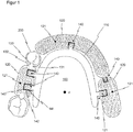
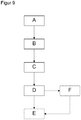
- Figure 1 shows a schematic top view of an exemplary embodiment of a dental prosthesis system 100 according to the invention, which is shown attached to an exemplary remaining tooth 200 of a patient.
- the remaining teeth 200 are part of the lower jaw, with two teeth for anchoring the dental prosthesis system 100 being shown in the left molar region.
- the dental prosthesis system 100 comprises a prosthesis base module 110 and three retention field modules 120, which are each designed as individual modules separately from one another.
- the basic prosthesis module 110 hugs the patient's palate and is designed here as a lower jaw bow.
- the retention field modules 120 each have a retention field 121, here in the form of a perforated plate, which rests on the ridge of the patient and forms a type of reinforcement or armouring for the dental prosthesis and the prosthesis saddle.
- the retention field module 120 assigned to the remaining teeth 200 in the left molar region also has two fastening means 131, each of which can be fastened to the remaining teeth 200 of the patient and shown fastened here, with which it is preferably designed in one piece.
- the fastening means 131 here each comprise a clamp 131 which engages around the remaining teeth 200 and a support 133 which is supported on a tooth surface 211 of the remaining teeth 200.
- a fastening means 131 can also comprise no, two or more clamps 132 and / or no, two or more supports 133.
- the individual modules, in this embodiment the prosthesis base module 110 and the three retention field modules 120 each have alignment means 140, which the prosthesis base module 110 and the three retention field modules 120 in one Align the predetermined position and / or position to one another, which corresponds to the insertion axis z of the dental prosthesis system 100.
- the insertion axis z is determined on the basis of the equatorial plane and the undercut depths of the remaining teeth 200 and is shown in FIG Figure 1 shown as an example pointing vertically into the plane of the drawing.
- An alignment means 140 each comprises an insert part 141 and a complementary guide receptacle 142.
- the insert part 141 is formed, in particular in one piece, on an individual module and the guide receptacle 142, in particular in one piece, on another individual module, the insert part 141 and the guide receptacle 142 with one another form a rail-like guide, which the two individual modules transfer to a defined end position so that they are aligned with one another in the intended position and / or position.
- the insert parts 141 can also each have a retention field 121.
- the prosthesis base module 110 is connected in one piece with a total of four insert parts 141.
- the retention field module 120 associated with the remaining teeth 200 has two guide receptacles 142, which are received for the guided reception of two associated, complementary insert parts 141 of the basic prosthesis module 100.
- the retention field module 120 assigned to the incisor region has a guide receptacle 142 for the guided reception of a complementary insert part 141 of the basic prosthesis module 110 and an insert part 141 which is received in a guided manner by a complementary guide receptacle 142 of the remaining retention field module 120 allocated to the right molar region.
- this retention field module 120 also has a guide receptacle 142 for the guided reception of a complementarily arranged insert part 141 of the prosthesis base module 100.
- the alignment means 140 are shown here in the end position that specifies the intended position and / or position, ie the insert parts 141 are each completely pushed into the guide receptacles 142 assigned to them.
- a bearing play 143 in a range between 0.01 mm and 5.0 mm, which imitates the natural tooth play of the teeth rooted in the jawbone, is provided between the insert part 141 and the guide receptacle 142.
- the inaccuracies and tolerances caused by the different manufacturing processes can be compensated for.
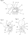
- FIG Figure 2 A schematic perspective side view of an exemplary embodiment of a dental prosthesis system 100 according to the invention is shown in FIG Figure 2 shown.
- a retention field module 120 and a fastening means module 130 are shown which, for example, form a dental prosthesis system 100 with a prosthesis base module 110 (not shown here).
- the fastening means module 130 is shown fastened to a remaining tooth 200 of a patient with a fastening means 131, here by way of example a clamp 132.
- the clip 132 is connected to an insert part 141 via a fastening arm 134; the clip 132, fastening arm 134 and insert part 141 are preferably formed in one piece.
- the insert part 141 has a particularly uncomplicated, cuboid basic shape, but can alternatively also be designed in other suitable geometric shapes.
- the insert part 141 is also provided with a retention field 121.
- the insert part 141 forms the alignment means 140.
- the guide receptacle 142 is part of the retention field module 120 and is preferably arranged in one piece on the upper side of its retention field 121, ie on the side facing away from the alveolar ridge when the prosthesis system 100 is inserted.
- the guide receptacle is shown open at the top, ie on the side facing away from the retention area 121.
- Insertion part 141 and guide receptacle 142 lie loosely one inside the other in a completely inserted end position, whereby the fastening means module 130 and the retention field module 120 are aligned in the intended position and / or position corresponding to the insertion axis z.
- a bearing play 143 in a range of 0.01 mm to 5.00 mm is again provided in order to compensate, for example, the inaccuracies and tolerances caused by different manufacturing processes.
- FIG. 3 shows a schematic perspective side view of a very similar exemplary embodiment of a dental prosthesis system according to the invention 100 with a retention field module 120 and a fastener module 130.
- the fastening means module 130 has a two-part fastening means 131, also referred to as a hybrid fastening means, a first part comprising a fastening means arm 134 and a second part comprising a bracket 132.
- the two-part design makes it possible to design the fastening means 131 to include two different materials.
- the two materials can have spring hardnesses and / or color properties and / or melting properties that differ from one another.
- the two parts of the fastening means 131 can, for example, be aligned with one another via a plug connection 135 and connected to one another by means of a connecting means 150, which is not visible here.
- Figure 4 shows a schematic top view of an exemplary embodiment of the invention of a dental prosthesis system 100 with a two-part fastening means module 130, in which both the fastening means 131, in particular the clip 132, and the alignment means 140, in particular the insert part 141, are designed in two parts.
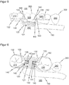
- FIG. 5 a schematic side view of an exemplary embodiment of a prosthesis system 100 according to the invention is shown in a basic version.
- the partial section of the prosthesis system 100 shown here comprises a retention field module 120 and two fastener modules 130.
- the retention field module 120 in addition to the retention field 121, also includes a lower jaw bow or is designed in one piece with the prosthesis base module 110.
- the prosthesis base module 110 it is also conceivable for the prosthesis base module 110 to be designed as a separate individual module or for the prosthesis base module 110 to have a retention area 121 connected in one piece.
- two guide receptacles 142 are formed in the cuboid shape already described.
- An insert part 141 is seated in each of the guide receptacles 142 (see plan view from FIG Figure 6 ) of the respective fastening means module 130.
- Each guide receptacle 142 with the insert part 141 arranged therein together form alignment means 140.
- the two fastening means modules 130 are attached to the Remaining teeth 200 of the patient attached, one of the fastening means modules 130 being attached to a first tooth 210 and the other being attached to a third tooth 230 of the remaining teeth 200.
- a fourth tooth 240 of the remaining teeth 200 is shown adjacent to the third tooth 230.
- the patient's second tooth which was originally located between the first tooth 210 and the third tooth 230, has already failed and is being replaced by the tooth replacement 300 indicated by dashed lines.
- a second replacement tooth 320 together with the prosthesis saddle 350 of the dental prosthesis 300, is therefore cast into the retention field 121, which acts as a reinforcement or reinforcement.
- the second replacement tooth 320 and the prosthesis saddle 350 act as connecting means 150 in order to connect the retention field module 120 to the two fastening means modules 130 in the position and / or position aligned by the alignment means 140.
- the exemplary embodiment of the prosthesis system 100 according to the invention is shown in a schematic plan view. Compared to the Figure 5 the broken line representation of the dental prosthesis 300 is dispensed with.
- the cuboidal design of the guide receptacle 142 of the alignment means 140 which is open upwards, ie in the direction of the tooth surface 211, as a result of which the respectively associated slide-in part 141 can be inserted from above.
- the bearing play 143 between the guide receptacle 142 and the insert part 141 lies in a range between 0.01 mm and 5.0 mm.
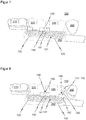
- the exemplary embodiment of a dental prosthesis system 100 according to the invention according to FIG Figure 5 is in the Figure 7 shown in a first optional expansion version.
- the extension version also takes into account the loss of the patient's third tooth 230, which now also has to be replaced with the aid of the prosthesis system 100.
- the modular structure of the dental prosthesis system 100 enables the fastening means module 130 originally attached to the third tooth 230 to be replaced by a replacement module, in this case a retention field module 120 with a retention field 121.
- the replacement module has an insert part that engages complementarily into the guide receptacle 142 of the adjacently arranged retention field module 120 141 on or is formed integrally therewith.
- the connecting means 150 is released, for example by heating it.
- the fastener module 130 can then be pulled out of the guide receptacle 142 and replaced by the replacement module designed as a retention field module 120.
- a third replacement tooth 330 and the associated section of the prosthetic saddle 350 are then cast into the retention field 121 of the replacement module, whereby the connecting means 150 is formed again at the same time.
- a retention field module 120 with a retention field 121 an insert part 141 which, together with the guide receptacle 142 of the adjacently arranged retention field module 120 of the prosthesis system 100, forms an alignment means 140, which is additionally designed with a guide receptacle 142, can be provided as the first replacement module.
- This guide receptacle 142 in turn forms an alignment means 140 with an insert part 141 of a second replacement module, namely a fastening means module 130, which has a bracket 132 as fastening means 131 for fastening to the previously unused fourth tooth 240.
- the modules are exchanged as described above.
- the Figure 9 shows a flowchart of an exemplary sequence of the method according to the invention for producing and / or expanding an exemplary embodiment of a dental prosthesis system 100 according to the invention. The method shown is discussed below using the exemplary embodiments according to the figures described above.
- a prosthesis base module 110 in particular an upper jaw plate or a lower jaw bracket, as well as three retention field modules 120 with retention fields 121 for connection to dentures 300 and partly additionally with fastening means 131 for fastening the dental prosthesis system 131 to the remaining teeth 200 of a patient.
- a virtual or physical model of the Oral situation ie the jaw and palate geometry as well as the remaining teeth 200 of the patient are created and a possible insertion axis z along which the dental prosthesis system 100 can be inserted into the remaining teeth 200 of the patient and can be attached to it is determined in a second method step B on the basis of the model.
- the position and / or position of the basic prosthesis module 110 and of the retention field modules 120 corresponding to the insertion axis z is specified in a third method step C by means of alignment means 140 (see also FIG Figure 1 ).
- a fourth method step D the individual modules aligned in the position and / or position corresponding to the insertion axis z and predetermined by the alignment means 140, for example according to FIG Figure 5 a retention field module 120 with an integrated lower jaw bracket, as well as two fastening means modules 130 releasably connected to one another by means of a connecting means 150.
- the connecting means 150 comprises a cast and moldable plastic, in particular a flowable cold polymer, and is cast to connect the individual modules and also in method step D to form the dental prosthesis 300.
- one or more replacement modules suitable for expansion and / or replacement are optionally already installed in method step A or in an optional method step F, according to FIG Figure 8
- a retention field module 120 and a fastener module 130 are provided, whose position and / or position to one another and to the other individual modules is determined either on the basis of the originally determined insertion axis z or on the basis of a newly determined insertion axis z and is specified by the alignment means 140.
- connection between the individual modules can be released in a fifth method step E by heating the connecting means 150 and an individual module, according to FIG Figure 7 a Fastener module 130 by the corresponding replacement module, according to FIG Figure 7 a retention field module 120 can be replaced.
- the Figures 10 and 11 each show a schematic top view of a third or fourth exemplary embodiment of a dental prosthesis system 100 according to the invention, each of which is a lower jaw bracket ( Figure 10 ) or as a jaw plate ( Figure 11 ) formed prosthesis base module 110 with two integrally adjoining slide-in parts 141.
- the alignment of the insert parts 141 is directed in the direction of the alveolar ridge.
- the prosthesis system 100 further comprises a retention field module 120 with two guide receptacles 142 complementary to the insert parts 141 as well as a retention field 121 and two fastening means 131 Figure 11
- the insert parts 141 can also be inserted appropriately into a respective guide receptacle 142 of two individual retention field modules 120.
- the two individual retention field modules 120 each have a retention field 121 and a fastening means 131.
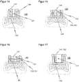
- FIG Figure 12 A schematic top view of a first exemplary embodiment of an alignment means 140 for a dental prosthesis system 100 according to the invention is shown in FIG Figure 12 shown, an associated sectional view shows the Figure 13 .
- the alignment means 140 is basically designed in the already described cuboid geometry that is open at the top.
- the guide receptacle 142 connected to the retention field 121 of the retention field module 120 comprises retaining means 144, which form an anchoring and additional guide for the insert part 141 of the fastening means module 130 that can be pushed into the guide receptacle 142 at the side.
- FIG Figure 14 A similar embodiment of an alignment means 140 with retaining means 144 is shown in FIG Figure 14 refer to.
- the retaining means 144 are designed in one piece, both on the insert part 141 and on the guide receptacle 142, to interlock in a complementary manner.
- the Figures 15 to 17 each show a schematic partial section in side view of exemplary embodiments of a connecting means 150 for a dental prosthesis system 100 according to the invention.
- the connecting means 150 can basically according to the connections known from the prior art, such as special adhesives, lasers, soldering, matrix and patrix attachment connections as well as grid and slide-in systems or connections based on adhesion and friction forces, such as those made according to the known telescope and conical crown principle be.
- the insert parts 141 of the Figures 14 to 17 are each interspersed with exemplary configurations of retention fields 121.
- a detachable connection between the guide receptacle 142 and the insert part 141 is implemented by a connecting means 150 designed as two bolts 151 running parallel to the direction of insertion of the insert part 141 into the guide receptacle 142.
- the connecting means 150 is formed by a single bolt 151 extending orthogonally to the direction of insertion
- the Figure 17 shows a T-bolt-like insert part 141 as a connecting means 150.
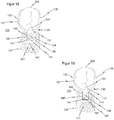
- FIG. 18 and 19 each shows a schematic top view of a first and a second exemplary embodiment of a spring force means 145 provided on the alignment means 140, more precisely on the insertion part 141 of the alignment means 140.
- the spring force means 145 comprises a spring slot 146 which extends along the insertion part 141 of the fastening means 131 designed as a bracket 132 or its fastening means arm 134 and a first bracket arm 136 and a second bracket arm 137 parallel to one another in the tooth equatorial plane of the remaining tooth 200 and / or a plane resiliently mounted to the tooth equatorial plane.
- a spring bore 147 is formed at one end of the spring slot 146.
- the geometry of the spring slot 146, in particular its length and the spring bore 147, in particular its diameter, but also the positioning of the spring bore 147 and the resulting wall thickness of the insert part 141 are used to set the spring stiffness.
- the bearing play 143 between the insertion part 141 and the guide receptacle 142 is filled with silicone before the connecting means 150 is attached. In this way, for example, a mobility of the insert part 141 within the guide receptacle 142 within the framework of the bearing play 143 on the one hand, and on the other hand, the push-in part 141 and the clamp arms 136, 137 can be spread open.
- the first exemplary embodiment shown has a single spring force means 145 with a spring slot 146 and a spring bore 147, as a result of which the first clamp arm 136 is essentially movably mounted, in particular so as to be resiliently expandable.
- two spring force means 145 with a respective spring slot 146 and spring bore 147 can be provided in order to mount both the first clamp arm 136 and the second clamp arm 137 movably, in particular so as to be resiliently expandable.
- the holding force can advantageously be increased and at the same time the abrasion of the remaining teeth 200 can be reduced by a more even distribution of the contact pressure over a larger area of the contact surface of the clamp arms 136, 137.
Landscapes
- Health & Medical Sciences (AREA)
- Oral & Maxillofacial Surgery (AREA)
- Dentistry (AREA)
- Epidemiology (AREA)
- Life Sciences & Earth Sciences (AREA)
- Animal Behavior & Ethology (AREA)
- General Health & Medical Sciences (AREA)
- Public Health (AREA)
- Veterinary Medicine (AREA)
- Dental Prosthetics (AREA)
Abstract
Die Erfindung betrifft ein Zahnprothesensystem (100), aufweisend mindestens ein Prothesenbasismodul (110), insbesondere eine Oberkieferplatte oder einen Unterkieferbügel, ein oder mehrere Retentionsfeldmodule (120) zur Verbindung mit Zahnersatz und/oder ein oder mehrere Befestigungsmittelmodule (130) zur Befestigung des Zahnprothesensystems (100) an der Restbezahnung (200) eines Patienten. Es ist die Aufgabe der vorliegenden Erfindung, ein Prothesensystem zu schaffen, welches, kostengünstig nach unterschiedlichen Verfahren hergestellt, z.B. gegossen und/oder gefräst werden kann und außerdem in einfacher Weise erweiterbar und/oder reparierbar ist. Die Aufgabe wird dadurch gelöst, dass das mindestens eine Prothesenbasismodul (110), das eine oder die mehreren Retentionsfeldmodule (120) sowie das eine oder die mehreren Befestigungsmittelmodule (130) modular als separate Einzelmodule (110, 120, 130) ausgebildet sind und jeweils über Ausrichtmittel (140) in einer durch die Ausrichtmittel (140) zueinander vorgegebenen Stellung und/oder Position derart ausrichtbar sind, dass das Zahnprothesensystem (100) entlang einer Einschubachse (z) in die Restbezahnung (200) des Patienten einführbar und daran befestigbar ist.The invention relates to a dental prosthesis system (100), having at least one prosthesis base module (110), in particular an upper jaw plate or a lower jaw bracket, one or more retention field modules (120) for connection to dentures and / or one or more fastener modules (130) for fastening the dental prosthesis system ( 100) on the remaining teeth (200) of a patient. It is the object of the present invention to create a prosthesis system which can be manufactured inexpensively by different methods, e.g. cast and / or milled, and which can also be easily expanded and / or repaired. The object is achieved in that the at least one prosthesis base module (110), the one or more retention field modules (120) and the one or more fastener modules (130) are modularly designed as separate individual modules (110, 120, 130) and each have Alignment means (140) can be aligned in a position and / or position predetermined by the alignment means (140) in such a way that the dental prosthesis system (100) can be inserted and fastened along an insertion axis (z) into the remaining teeth (200) of the patient.
Description
Die Erfindung betrifft ein Zahnprothesensystem, aufweisend mindestens ein Prothesenbasismodul, insbesondere eine Oberkieferplatte oder einen Unterkieferbügel, ein oder mehrere Retentionsfeldmodule zur Verbindung mit Zahnersatz und/oder ein oder mehrere Befestigungsmittelmodule zur Befestigung des Zahnprothesensystems an der Restbezahnung eines Patienten.The invention relates to a dental prosthesis system, having at least one prosthesis base module, in particular an upper jaw plate or a lower jaw bracket, one or more retention field modules for connection to dentures and / or one or more fastener modules for fastening the dental prosthesis system to the remaining teeth of a patient.
Die Erfindung betrifft außerdem ein Verfahren zur Herstellung und/oder zur Erweiterung eines Zahnprothesensystems.The invention also relates to a method for producing and / or expanding a dental prosthesis system.
Der Fachbereich des prothetischen und herausnehmbaren Zahnersatzes umfasst Teil- und Totalprothesen sowie deren Herstellung und Einpassung in den Mundraum eines Patienten. Teilprothesen, auch als partielle Prothesen bezeichnet, ersetzen hierbei nur einen Teil der Zähne und können an der Restbezahnung des Patienten befestigt werden. Eine einfache Ausführung einer Teilprothese umfasst eine sogenannte Prothesenbasis, aus Kunststoff oder Metall, welche sich als Platte oder Bügel an den Gaumen des Patienten anpasst. Gängige Ausführungen sind die so bezeichnete Oberkieferplatte sowie der Unterkieferbügel. Mit der Prothesenbasis sind Befestigungsmittel aber auch Retentionsfelder verbunden. Die Befestigungsmittel, zumeist sogenannte Klammern, die einen Zahn umgreifen und/oder Auflagen, die auf einem Zahn aufliegen, dienen zur Befestigung und Abstützung an einem oder mehreren Zähnen der noch vorhandenen Restbezahnung des Patienten. Die Retentionsfelder liegen auf dem Kieferkamm auf und bilden eine Art Bewehrung oder Armierung für den Zahnersatz. Der Zahnersatz selbst, d. h. die künstlichen Zähne sowie der den Kieferkamm umgebende Prothesensattel werden vom Zahntechniker für gewöhnlich aus Kunststoff in die als Bewehrung dienenden Retentionsfelder eingegossen.The field of prosthetic and removable dentures includes partial and full dentures as well as their manufacture and fitting into the oral cavity of a patient. Partial dentures, also known as partial dentures, only replace part of the teeth and can be attached to the patient's remaining teeth. A simple version of a partial prosthesis comprises a so-called prosthesis base, made of plastic or metal, which adapts to the patient's palate as a plate or bracket. Common designs are the so-called upper jaw plate and the lower jaw bracket. Fastening means but also retention fields are connected to the prosthesis base. The fastening means, mostly so-called brackets, which grip around a tooth and / or supports which rest on a tooth, are used to fasten and support one or more teeth of the remaining teeth of the patient. The retention fields lie on the alveolar ridge and form a type of reinforcement or armouring for the dental prosthesis. The dentures themselves, d. H. The artificial teeth and the prosthetic saddle surrounding the alveolar ridge are usually cast from plastic by the dental technician into the retention fields that serve as reinforcement.
Im Stand der Technik werden solche Teilprothesen üblicherweise als einstückige Modellgussprothese im Zahnlabor aus Kunststoff oder Metall hergestellt. Die Prothesenbasis ist einstückig mit Klammern und Retentionsfeldern verbunden. Die Modellgussprothesen werden hierzu zunächst aus Wachsfertigteilen per Hand modelliert oder aber mit einer 3D-Software erstellt und anschließend von einem 3D-Drucker geplottet. Die Modellationen werden in Einbettmasse eingebettet und ausgeschmolzen. Die nach dem Ausschmelzen oder Ausbrennen entstandenen Hohlräume in der Einbettmasse werden dann mit einer Modellgusslegierung, wie z.B. einer Chrom-Cobalt-Molybdän-Legierung gefüllt. Anschließend werden Einbettmasse und Angussstifte entfernt und der Modellguss sandgestrahlt, elektrolytisch geglänzt, aufgepasst und hochglanzpoliert.In the prior art, such partial prostheses are usually produced as a one-piece model cast prosthesis in the dental laboratory from plastic or metal. The prosthesis base is connected in one piece with clips and retention panels. The model cast prostheses are first modeled by hand from precast wax parts or created with 3D software and then plotted by a 3D printer. The models are embedded in investment material and melted out. The cavities in the investment material that are created after melting or burning out are then filled with a model casting alloy, such as a chromium-cobalt-molybdenum alloy. Then the investment material and sprue pins are removed and the model casting is sandblasted, electrolytically polished, fitted and polished to a high gloss.
Alternativ kann eine solche Modellgussprothese auch aus einem Edelstahlblock herausgefräst werden, allerdings bestehen zwischen den Klammern und dem tiefsten Punkt, z.B. dem Gaumendach, Höhenunterschiede von bis zu 30 mm. Daher werden 30 mm hohe Edelstahlböcke benötigt, um die Modellgussprothese vollständig herausfräsen zu können. Bedenkt man jedoch, dass eine Gaumenkieferplatte nur eine Wandstärke von 0,30 mm - 1,00 mm aufweist, entstünde bei solchen Vorgängen ein sehr unwirtschaftliches Verhältnis mit einem Materialverlust von ca. 95 % sowie einem ausgesprochen hohen Werkzeugverschleiß bei der CAD-CAM Bearbeitung. Aus diesem Grund wird heutzutage auch auf digitale Herstellungsmethoden, wie die bekannte SLM-Technologie (selektives Laserschmelzen) zurückgegriffen. Diese Laser-Sinter-Technologie benötigt bei hohen Bauteilen aber auch eine ca. 50% höhere Fertigungszeit. Außerdem kann es bei diesen Übermaßen zu Spannungen sowie hohen Ungenauigkeiten kommen.Alternatively, such a model cast prosthesis can also be milled out of a stainless steel block, but there are height differences of up to 30 mm between the brackets and the lowest point, e.g. the roof of the mouth. Therefore, 30 mm high stainless steel brackets are required in order to be able to completely mill out the model cast prosthesis. However, if you consider that a palatal plate only has a wall thickness of 0.30 mm - 1.00 mm, such processes would result in a very uneconomical ratio with a material loss of approx. 95% and extremely high tool wear during CAD-CAM processing. For this reason, digital manufacturing methods such as the well-known SLM technology (selective laser melting) are used nowadays. However, this laser-sintering technology also requires around 50% more production time for tall components. In addition, these excesses can lead to tension and high inaccuracies.
Im Anschluss an die Herstellung erfolgt das zeitaufwendige und schwierige Aufpassen der gesamten Konstruktion der Modellgussprothese auf einem Gipsmodell des Mundraums und Kiefers mit Restbezahnung des Patienten. Dieses empfindliche Gipsmodell dient bis heute als einzige Kontrollmöglichkeit für die Endpassung der Modellgussprothese an die Mundraum- und Kieferstruktur des Patienten. Hierzu wird die Modellgussprothese vorsichtig auf das Gipsmodell aufgepasst und alle möglichen Fehlerquellen, wie z.B. fehlerhafte Abdrücke des Zahnarztes, Scanfehler, fehlerhafte Gipsexpansionen, fehlerhafte Einbettmassenmischungen, Einbettfehler durch Lufteinschlüsse - einschließlich Lunker und Oxidationen der Legierungen - sowie Fehler durch Fräswerkabnutzungen, Verzüge der 3D-gedruckten Kunststoffkonstruktionen oder Sinterkonstruktionen usw. vom Zahntechniker per Hand durch mühsames Schleifen der Modellgussprothese ausgeglichen. Die Modellgussprothese wird immer wieder auf das empfindliche Gipsmodell gedrückt, bis diese, ohne zu kippeln und mit einer Genauigkeit von ca. 0,01 mm auf das Gipsmodell passt. Wird hierbei jedoch das Gipsmodell beschädigt, ist eine ausreichende Genauigkeit nicht mehr zu erreichen.Following production, the entire construction of the model cast prosthesis is time-consuming and difficult to fit onto a plaster model of the oral cavity and jaw with the patient's remaining teeth. This sensitive plaster model is still used today as the only control option for the final fit of the model cast prosthesis to the patient's oral cavity and jaw structure. For this purpose, the model casting prosthesis is carefully fitted onto the plaster model and all possible sources of error, such as incorrect impressions by the dentist, scanning errors, defective plaster expansions, defective investment mixes, investment errors due to air inclusions - including cavities and oxidation of the alloys - as well as errors due to milling tool wear, distortions of the 3D printed ones Plastic constructions or sintered constructions etc. are balanced by the dental technician by hand by laborious grinding of the model cast prosthesis. The model cast prosthesis is pressed repeatedly onto the sensitive plaster model until it, without tilting and with a Accuracy of approx. 0.01 mm fits the plaster model. However, if the plaster model is damaged in the process, sufficient accuracy can no longer be achieved.
Auch ist es beispielsweise beim Ersetzen einer oder mehrerer abgebrochener Klammern aufwändig, die ursprünglich vorgesehene Einschubachse abzuschätzen. Die Einschubachse ist die Achsrichtung entlang derer die Teilprothese in den Mundraum des Patienten eingeschoben wird. Zur Festlegung der Einschubachse sind Hinterschnitttiefen von Befestigungsmitteln wie Klammern sowie die Äquatorialebene der Restbezahnung zu berücksichtigen, wobei die Einschubachse senkrecht zur Äquatorialebene der Restbezahnung steht. Beispielsweise ist aus der
Gerade bei einstückig hergestellten Modellgussprothesen wäre, z.B. bei Verlust eines zur Befestigung der Teilprothese verwendeten Restzahnes, eine Erweiterung um zu ergänzende, künstliche Zähne mit hohen Kosten verbunden, da Klammern und Auflagen herausgeschliffen werden müssen und die Modellgussbasis aufwendig umgearbeitet werden muss. Auch ist oftmals eine Erweiterung wirtschaftlich nicht sinnvoll, bspw. sofern neue Klammern, Auflagen und/oder Retentionsfelder für neue Kunststoffzähne aufwendig angelötet werden müssten. Die beim Löten entstehende große Hitze bedingt nämlich auch, dass die schon vorhandenen Kunststoffzähne der Modellgussprothese entfernt und später wieder neu eingearbeitet werden müssten. In diesen Fällen bleibt als einzige Möglichkeit eine ebenfalls teure Neuanfertigung.Especially in the case of one-piece model cast prostheses, e.g. if a remaining tooth used to fix the partial prosthesis is lost, adding artificial teeth to be added would be associated with high costs, since brackets and supports have to be ground out and the model cast base has to be laboriously reworked. An extension is also often not economically viable, for example if new brackets, supports and / or retention fields for new plastic teeth would have to be soldered on in a laborious manner. The high heat generated during soldering also means that the plastic teeth that are already present in the model cast prosthesis have to be removed and re-incorporated later. In these cases, the only option is an expensive new production.
Eine Vorrichtung zum Zahnersatz oder zur Zahnregulierung, bei der drahtförmige Befestigungselemente einzeln hergestellt und in einen auf dem Zahnfleisch und/oder dem Gaumen aufliegenden und aus Gießharz bestehenden Teil eingegossen werden, ist aus der
Eine nicht-stoffschlüssige Verbindung zwischen einem Verankerungsteil, z.B. einer Krone und einem daran über eine lösbare Verbindungseinrichtung, wie Geschiebe, Riegel, Schraube oder dergl., gehaltenen Prothesengerüst oder Modellguss ist aus der
Nachteilig ist hier, dass die beschriebene, formschlüssige Verbindung durch Aufgießen der Krone aus naheliegenden Gründen nicht zur Befestigung an der natürlichen Restbezahnung eines Patienten geeignet ist. Darüber hinaus ist auch eine Erweiterung der Prothese nach wie vor aufwendig, neue Prothesenteile müssen stets auf den Verbinder aufgegossen werden, eine Herstellung durch ein spanabhebendes CAD-CAM-Verfahren oder einen 3D-Drucker ist ebenfalls nicht möglich.The disadvantage here is that the form-fitting connection described by pouring on the crown is not suitable for attachment to the natural remaining teeth of a patient for obvious reasons. In addition, an expansion of the prosthesis is still complex, new prosthesis parts must always be poured onto the connector, a production by a Machining CAD-CAM processes or a 3D printer are also not possible.
Es ist die Aufgabe der vorliegenden Erfindung, die Nachteile aus dem Stand der Technik zu eliminieren und insbesondere ein Prothesensystem zu schaffen, welches, kostengünstig nach unterschiedlichen Verfahren hergestellt, z.B. gegossen und/oder gefräst werden kann und außerdem in einfacher Weise erweiterbar und/oder reparierbar ist.It is the object of the present invention to eliminate the disadvantages of the prior art and, in particular, to create a prosthesis system which can be manufactured inexpensively using different methods, eg cast and / or milled, and which can also be easily expanded and / or repaired is.
Die Aufgabe wird gelöst durch ein Zahnprothesensystem gemäß Anspruch 1.The object is achieved by a dental prosthesis system according to claim 1.
Ein erfindungsgemäßes Zahnprothesensystem der eingangs näher beschriebenen Art kennzeichnet sich dadurch, dass das mindestens eine Prothesenbasismodul, das eine oder die mehreren Retentionsfeldmodule sowie das eine oder die mehreren Befestigungsmittelmodule modular als separate Einzelmodule ausgebildet sind und jeweils über Ausrichtelemente in einer durch diese Ausrichtelemente zueinander vorgegebenen Stellung und/oder Position derart ausgerichtet oder ausrichtbar sind, dass das Prothesensystem entlang einer, insbesondere Hinterschnitttiefen und/oder die Äquatorialebene der Restbezahnung berücksichtigenden Einschubachse in die Restbezahnung des Patienten einführbar und daran befestigbar ist.A dental prosthesis system according to the invention of the type described in more detail at the outset is characterized in that the at least one prosthesis base module, the one or more retention field modules and the one or more fastener modules are modularly designed as separate individual modules and each have alignment elements in a position and position predetermined by these alignment elements / or position are aligned or alignable in such a way that the prosthesis system can be inserted into the remaining teeth of the patient and attached to it along an insertion axis, in particular undercut depths and / or the equatorial plane of the remaining teeth.
Die Erfindung sieht also vor, erforderliche Bestandteile einer Zahnprothese modular, jeweils als Einzelmodule separat voneinander auszubilden und mittels Ausrichtmitteln eine Stellung, bspw. einen Winkel, und/oder Position, bspw. Prämolar 15, Molar 26, Inzisiv 11 usw. der Einzelmodule zueinander vorzugeben, sodass die in dieser Stellung und/oder Position zueinander ausgerichteten Einzelmodule gemeinsam eine Zahnprothese ausbilden, die entlang einer möglichen, insbesondere die Äquatorialebene und Hinterschnitttiefen berücksichtigenden, Einschubachse in die Restbezahnung des Patienten eingeführt werden kann und an dieser befestigbar ist. Durch den Einsatz von Ausrichtmitteln wird ermöglicht, die Einzelmodule voneinander getrennt bzw. separat herzustellen und anschließend zueinander mit einer gemeinsamen Einschubachse auszurichten. Der Begriff Restbezahung ist nicht ausschließlich auf natürliche Zähne des Patienten begrenzt, sondern umfasst auch Implantate und/oder Kronen, die bereits fest in das Gebiss integriert sind oder auch erst zu einem späteren Zeitpunkt integriert werden können.The invention therefore provides for the necessary components of a dental prosthesis to be designed modularly, each as individual modules, and to specify a position, for example an angle, and / or position, for example premolar 15, molar 26, incisive 11, etc., of the individual modules to one another by means of alignment means So that the individual modules aligned with one another in this position and / or position jointly form a dental prosthesis that can be inserted into the remaining teeth of the patient along a possible insertion axis, particularly taking into account the equatorial plane and undercut depths, and can be attached to it. The use of alignment means enables the individual modules to be produced separately from one another or separately and then to align them with one another with a common insertion axis. The term remaining payment is not limited exclusively to the patient's natural teeth, but also includes implants and / or crowns that are already are firmly integrated into the bit or can only be integrated at a later point in time.
Die Herstellung der Einzelmodule, also des mindestens einen Prothesenbasismoduls, des einen oder der mehreren Retentionsfeldmodule und des einen oder der mehreren Befestigungsmittelmodule kann nach bekannten Verfahren, z. B. durch Gießen, durch selektives Lasersintern, aber auch in einem CAD-CAM-Fräsverfahren oder 3D-Druck erfolgen. Besonders bei letzterem Herstellungsverfahren ergibt sich als besonderer Vorteil, dass die Gesamthöhe des Fräsblocks erheblich, insbesondere um ca. 50 % gegenüber einer nicht modularen Herstellung, verringert werden kann, da die Einzelmodule nicht bereits beim Herausfräsen in der zueinander vorgesehenen Stellung und/oder Position angeordnet sein müssen. So ist es beispielsweise auch denkbar aus einem Fräsblock eine Art von Einzelmodulen, bspw. Befestigungsmodule und aus einem anderen Fräsblock eine andere Art von Einzelmodulen, bspw. Prothesenmodule und/oder Retentionsmodule herauszufräsen, wodurch die Gesamthöhe des Fräsblocks und der Materialverbrauch weiter gesenkt werden, aber auch erforderliche Einzelteile zeitgleich angefertigt werden können, wodurch wiederum die Produktionszeiten sinken. Die Ermittlung der Einschubachse kann über dem Fachmann bekannte Methoden erfolgen, bspw. manuell am physikalischen Arbeitsmodell mithilfe eines Parallelometers oder aber softwaregestützt, z.B. durch Erstellen eines virtuellen Arbeitsmodells. Die Ausrichtmittel können dann anhand der ermittelten Einschubachse derart ausgebildet werden, dass die Einzelmodule mittels der Ausrichtelemente in der der Einschubachse entsprechenden Stellung und/oder Position zueinander ausrichtbar sind. Die Einschubachse berücksichtigt den gesamten Restzahnbestand, Kronen und Implantate des Gebisses, um präzise Unterschnitte am jeweiligen Zahnäquator zu definieren.The production of the individual modules, that is to say of the at least one basic prosthesis module, of the one or more retention field modules and of the one or more fastener modules, can be carried out according to known methods, e.g. B. by casting, by selective laser sintering, but also in a CAD-CAM milling process or 3D printing. With the latter manufacturing method, there is a particular advantage that the total height of the milling block can be reduced considerably, in particular by approx. 50% compared to a non-modular manufacture, since the individual modules are not already arranged in the intended position and / or position when they are milled out must be. For example, it is also conceivable to mill one type of individual modules, e.g. fastening modules, from a milling block and another type of individual modules, e.g. prosthesis modules and / or retention modules, from another milling block, whereby the total height of the milling block and the material consumption are further reduced, however required individual parts can also be produced at the same time, which in turn reduces production times. The insertion axis can be determined using methods known to those skilled in the art, for example manually on the physical working model with the aid of a parallelometer or with the aid of software, e.g. by creating a virtual working model. The alignment means can then be designed on the basis of the determined insertion axis in such a way that the individual modules can be aligned with one another by means of the alignment elements in the position and / or position corresponding to the insertion axis. The insertion axis takes into account the entire remaining teeth, crowns and implants of the dentition in order to define precise undercuts at the respective tooth equator.
Insgesamt wird mit der erfindungsgemäßen Lösung ein Zahnprothesensystem bereitgestellt, welches aufgrund von kürzeren Maschinenfertigungszeiten und geringerem Materialaufwand kostengünstig maschinell herstellbar ist. Auch der Arbeitsaufwand und die Schwierigkeit der durchzuführenden Anpassungen für den Zahntechniker lassen sich durch den modularen Aufbau erheblich reduzieren, weshalb die Herstellungskosten weiter sinken. Der modulare Aufbau ermöglicht außerdem das Zahnprothesensystem z. B. durch den Zahnarzt direkt am Patienten anzupassen. Weiterhin können die fortwährend auftretenden Spannungen, welche durch die Herstellung z. B. einer Modellgussbasis oder aufgrund der Klammern und/oder Auflagen entstehen vermieden werden, sodass bei der Eingliederung am Patienten ein spannungsfrei sitzender Zahnersatz gewährleistet wird. Die höchste Präzision bei der Herstellung von Zahnersatz erreicht man, wenn die Möglichkeit gegeben ist, die Bauteile direkt im Mund und unter Berücksichtigung der Eigenbeweglichkeit der Zähne sowie der Schleimhautresilienz, spannungsfrei zusammenzufügen. Erfindungsgemäß steht diese Möglichkeit dem behandelnden Zahnarzt zur Verfügung, indem die Befestigungsmittel getrennt von der Modellgussbasis überprüft werden können. Folglich können Passungsfehler sehr schnell lokalisiert und beseitigt werden. Damit bietet die erfinderische Lösung dem Behandler erstmalig eine schnelle und präzise Vorgehensweise.Overall, the solution according to the invention provides a dental prosthesis system which, due to shorter machine production times and lower material costs, can be machine-produced at low cost. The workload and the difficulty of the adjustments to be made for the dental technician can also be reduced considerably thanks to the modular structure, which is why the manufacturing costs are further reduced. The modular structure also enables the dental prosthesis system z. B. by the dentist directly on the patient adapt. Furthermore, the continuously occurring tensions, which are caused by the production z. B. a model cast base or due to the brackets and / or supports can be avoided, so that a tension-free seated denture is guaranteed when the patient is incorporated. The highest precision in the manufacture of dentures is achieved when there is the possibility of joining the components directly in the mouth, taking into account the mobility of the teeth and the resilience of the mucous membrane. According to the invention, this possibility is available to the treating dentist in that the fastening means can be checked separately from the model casting base. As a result, mismatches can be localized and eliminated very quickly. The inventive solution thus offers the practitioner a quick and precise procedure for the first time.
Vorteilhafte Ausführungsformen sind in den Unteransprüchen beansprucht und werden nachfolgend näher erläutert.Advantageous embodiments are claimed in the subclaims and are explained in more detail below.
So können gemäß einer beispielhaften Ausführung der Erfindung das eine oder die mehreren Retentionsfeldmodule mindestens ein Retentionsfeld zur Verbindung mit dem Zahnersatz und/oder das eine oder die mehreren Befestigungsmittelmodule mindestens ein Befestigungsmittel zur Befestigung des Zahnprothesensystems an der Restbezahnung eines Patienten aufweisen.According to an exemplary embodiment of the invention, the one or more retention field modules can have at least one retention field for connection to the dental prosthesis and / or the one or more fastening means modules can have at least one fastening means for fastening the dental prosthesis system to the remaining teeth of a patient.
Insbesondere sind das eine oder die mehreren Retentionsfeldmodule und das eine oder die mehreren Befestigungsmittelmodule jeweils einstückig mit dem mindestens einen Retentionsfeld bzw. dem mindestens einen Befestigungsmittel ausgebildet.In particular, the one or more retention field modules and the one or more fastening means modules are each formed in one piece with the at least one retention field or the at least one fastening means.
Zweckmäßigerweise ist es denkbar, ein Retentionsfeldmodul einstückig mit einem Retentionsfeld, welches als Bewehrung oder Armierung für den Zahnersatz dient und/oder ein Befestigungsmittelmodul einstückig mit einem Befestigungsmittel, bspw. einer Klammer zum Umgreifen eines Zahns und/oder einer Auflage zum Abstützen auf einer Zahnoberfläche und/oder einer Gegenlagerklammer zu gießen oder zu fräsen.It is expediently conceivable to have a retention field module in one piece with a retention field, which serves as reinforcement or reinforcement for the dental prosthesis, and / or a fastening means module in one piece with a fastening means, e.g. a bracket for gripping a tooth and / or a support for supporting on a tooth surface and / or to cast or mill a counter bearing bracket.
Je nach Zustand der Restbezahnung des Patienten, insbesondere abhängig von der Anzahl und der Position der zur Befestigung des Prothesensystems verwendbaren Zähne kann es nach einer alternativen oder optionalen Erfindungsvariante ebenso vorteilhaft sein, dass das eine oder die mehreren Retentionsfeldmodule sowohl mindestens ein Retentionsfeld zur Verbindung mit dem Zahnersatz als auch mindestens ein Befestigungsmittel zur Befestigung des Zahnprothesensystems an der Restbezahnung des Patienten aufweisen.Depending on the condition of the patient's remaining teeth, in particular depending on the number and position of those for fastening the prosthesis system usable teeth, according to an alternative or optional variant of the invention, it can also be advantageous that the one or more retention field modules have both at least one retention field for connection to the dental prosthesis and at least one fastening means for fastening the dental prosthesis system to the remaining teeth of the patient.
Sofern gewünscht kann durch Ausbildung eines Retentionsfeldmoduls, welches zusätzlich zum Retentionsfeld außerdem noch ein Befestigungsmittel aufweist, die Gesamtanzahl der Einzelmodule reduziert werden. Besonders vorteilhaft ist dies auch an Positionen im Mundraum des Patienten die verhältnismäßig wenig Raum für die Zahnprothese bereithalten. Ebenfalls denkbar ist nach einer anderen Erfindungsausgestaltung auch, das Prothesenbasismodul selbst mit einem Retentionsfeld auszubilden.If desired, the total number of individual modules can be reduced by designing a retention field module which, in addition to the retention field, also has a fastening means. This is also particularly advantageous at positions in the patient's mouth that have relatively little space available for the dental prosthesis. According to another embodiment of the invention, it is also conceivable to design the prosthesis base module itself with a retention field.
In vorteilhafter Ausführung der Erfindung weisen die Ausrichtmittel jeweils ein Einschubteil und eine komplementär dazu ausgebildete Führungsaufnahme auf, wobei das Einschubteil von der Führungsaufnahme in eine Endposition geführt und dort aufgenommen wird.In an advantageous embodiment of the invention, the aligning means each have an insert part and a complementary guide receptacle, the insert part being guided by the guide receptacle into an end position and received there.
Das Einschubteil und die Führungsaufnahme sind, insbesondere einstückig, an jeweils einem Einzelmodul ausgebildet und bilden miteinander eine schienenartige Führung, die die beiden Einzelmodule in eine festgelgte Endposition überführt. In dieser Endposition befinden sich die beiden Einzelmodule in der zueinander vorgesehenen Stellung und/oder Position, sodass das aus der Gesamtheit aller Einzelmodule gebildete Prothesensystem entlang der zuvor festgelegten und/oder bestimmten Einschubachse im Restgebiss des Patienten befestigbar ist. Vorzugsweise sind die jeweiligen Einschubteile geometrisch identisch ausgebildet, die gewünschte Endposition zur Ausrichtung in der vorgesehenen Stellung und/oder Position wird durch die Geometrie der Führungsaufnahme vorgegeben.The slide-in part and the guide receptacle are designed, in particular in one piece, on a single module each and together form a rail-like guide that moves the two single modules into a fixed end position. In this end position, the two individual modules are in the intended position and / or position with respect to one another, so that the prosthesis system formed from the entirety of all individual modules can be fastened along the previously established and / or determined insertion axis in the remaining dentition of the patient. The respective slide-in parts are preferably designed to be geometrically identical; the desired end position for alignment in the intended position and / or position is predetermined by the geometry of the guide receptacle.
Für die praktische Verwendung des Zahnprothesensystems, also bspw. wenn der Patient mit eingesetzter Prothese kaut, ist es gemäß einer Weiterbildung dieser Ausführungsvariante zweckmäßig, dass das Einschubteil innerhalb der Führungsaufnahme in der Endposition mit einem Lagerspiel, insbesondere mit einem Lagerspiel in einem Bereich zwischen 0,01 mm und 5,0 mm gelagert ist.For the practical use of the dental prosthesis system, for example when the patient is chewing with the prosthesis inserted, according to a further development of this embodiment variant, it is expedient for the insert part within the Guide receptacle is mounted in the end position with a bearing play, in particular with a bearing play in a range between 0.01 mm and 5.0 mm.
Auch die natürlichen Zähne sind nicht starr im Kieferknochen verankert, sondern verfügen ebenfalls über ein gewisses Spiel um beim Kauen auftretende Kräfte und Belastungen besser aufnehmen und ausgleichen zu können. Dieses natürliche Zahnspiel lässt sich zweckmäßig mit einem Lagerspiel zwischen Einschubteil und Führungsaufnahme nachbilden. Zu diesem Zweck kann das Lagerspiel, bevor das Befestigungsmittel angebracht wird, mit einem elastischen Werkstoff, insbesondere Silikon befüllt werden. Andererseits dient das Lagerspiel dazu, die bei den unterschiedlichen Herstellungsverfahren auftretenden Ungenauigkeiten und Toleranzen auszugleichen.The natural teeth are also not rigidly anchored in the jawbone, but also have a certain amount of play in order to be able to better absorb and compensate for forces and loads that occur during chewing. This natural tooth play can expediently be reproduced with a bearing play between the insert part and the guide receptacle. For this purpose, the bearing play can be filled with an elastic material, in particular silicone, before the fastening means is attached. On the other hand, the bearing play serves to compensate for the inaccuracies and tolerances that occur in the different manufacturing processes.
In Weiterbildung ist es vorteilhaft, dass das mindestens eine Prothesenbasismodul und/oder das eine oder die mehreren Retentionsfeldmodule und/oder das eine oder die mehreren Befestigungsmittelmodule jeweils mindestens ein Einschubteil aufweisen und mindestens ein Retentionsfeldmodul eine oder mehrere Führungsaufnahmen aufweist.In a further development, it is advantageous that the at least one prosthesis base module and / or the one or more retention field modules and / or the one or more fastening means modules each have at least one insert part and at least one retention field module has one or more guide receptacles.
In dieser beispielhaften Erfindungsausgestaltung sind die Führungsaufnahmen ausschließlich an den Retentionsfeldmodulen ausgebildet, deren Retentionsfelder auf den Kieferkamm des Patienten aufliegen. Das sich an den Gaumen anpassende Prothesenbasismodul sowie die mit Befestigungsmitteln, bspw. mit Klammern und/oder Auflagen ausgebildeten Befestigungsmittelmodule weisen jeweils mindestens ein Einschubteil auf und können zur gewünschten Ausrichtung entlang der Einschubachse in die Führungsaufnahmen der Retentionsfeldmodule eingeführt werden. Auf diese Weise können die entlang des Kieferkamms verlaufenden Retentionsfelder bzw. Retentionsfeldmodule einen Bezug bzw. den Ausgangspunkt zur Ausrichtung der Einzelmodule des Prothesensystems bilden. Natürlich können alternativ auch Führungsaufnahmen an dem Prothesenbasismodul und/oder an den Befestiungsmittelmodulen vorgesehen sein.In this exemplary embodiment of the invention, the guide receptacles are formed exclusively on the retention field modules, the retention fields of which rest on the patient's alveolar ridge. The prosthesis base module, which adapts to the palate, and the fastener modules designed with fastening means, e.g. with clips and / or supports, each have at least one insert part and can be inserted into the guide receptacles of the retention field modules for the desired alignment along the insertion axis. In this way, the retention fields or retention field modules running along the alveolar ridge can form a reference or the starting point for aligning the individual modules of the prosthesis system. Of course, guide receptacles can alternatively also be provided on the prosthesis base module and / or on the fastening means modules.
Beispielsweise kann nach einer Erfindungsvariante dann das eine oder die mehreren Befestigungsmittelmodule mittelbar über ein Retentionsfeld oder über ein Retentionsfeldmodul mit dem Prothesenbasismodul verbunden oder verbindbar sein.For example, according to a variant of the invention, the one or more fastener modules can then be used indirectly via a retention field or via a Retention field module connected or connectable to the prosthesis base module.
Während die Ausrichtmittel des Zahnprothesensystems zur Ausrichtung der Einzelmodule vorgesehen sind, ist gemäß einer bevorzugten Erfindungsausgestaltung zur Verbindung der Einzelmodule miteinander eigens ein Verbindungsmittel vorgesehen, über welches das mindestens eine Prothesenbasismodul, das eine oder die mehreren Retentionsfeldmodule sowie das eine oder die mehreren Befestigungsmittelmodule lösbar miteinander verbunden oder verbindbar sind.While the alignment means of the dental prosthesis system are provided for aligning the individual modules, according to a preferred embodiment of the invention, for connecting the individual modules to one another, a connection means is provided, via which the at least one prosthesis base module, the one or more retention field modules and the one or more fastening means modules are detachably connected to one another or are connectable.
Durch diese Ausgestaltung können die Funktionen, Ausrichten der Einzelmodule zueinander sowie Verbinden der Einzelmodule miteinander, separat von abweichenden Mitteln übernommen werden. Dies ermöglicht eine insgesamt höhere Flexibilität bei der Herstellung des Zahnprothesensystems und eine exaktere Ausrichtung der Einzelmodule zueinander, da die Ausrichtmittel keine Verbindungsfunktion aufweisen müssen.With this configuration, the functions, aligning the individual modules with one another and connecting the individual modules with one another, can be taken over separately by different means. This enables an overall greater flexibility in the manufacture of the dental prosthesis system and a more precise alignment of the individual modules with one another, since the alignment means do not have to have a connection function.
Indem die Verbindung lösbar ausgestaltet ist, kann das Zahnprothesensystem z. B. bei Verlust eines zur Befestigung vorgesehenen Restzahnes und/oder bei Beschädigung, beliebig und mit nur geringem Aufwand durch ein "Ersatzmodul" erweitert werden bzw. repariert werden. So ist bspw. denkbar, ein Befestigungsmittelmodul bei Verlust des zugehörigen Restzahns über die lösbare Verbindung gegen ein Retentionsfeldmodul als Basis für den an dieser Stelle erforderlich gewordenen Zahnersatz auszutauschen. Die korrekte Ausrichtung, d.h. Stellung und/oder Position des Ersatzmoduls, in diesem Beispiel des Retentionsfeldmoduls, zu den bereits vorhandenen Einzelmodulen, z. B. zu einem angrenzenden, anderen Retentionsfeldmodul und dem Prothesenbasismodul, wird wiederum über das Ausrichtmittel sichergestellt. Insbesondere wird ein Einschubteil des Ersatzmoduls in eine Führungsaufnahme eines angrenzenden Einzelmoduls, z. B. eines angrenzenden Retentionsfeldmoduls, eingeführt. Die digitalen Verarbeitungssysteme (z.B. CAD-CAM, SLM oder 3D-Drucker) können heutzutage die geometrischen Daten der Einschubteile und Führungsaufnahmen in die bestehende Software implementieren. Somit lassen sich mit einfacher digitaler Handhabung die gewünschten Befestigungsmittel mit Einschubteilen und Führungsaufnahmen inklusive aller Retentionsfelder für neue Prothesenzähne wunschgemäß dimensionieren. Für händische Verfahren können die gewohnten Arbeitsprozesse durch vorgefertigte Einschubteile, Führungsaufnahmen und/oder Retentionsfelder, beibehalten werden.By making the connection releasable, the dental prosthesis system can, for. B. in the event of loss of a remaining tooth intended for attachment and / or damage, can be expanded or repaired at will and with little effort by a "replacement module". For example, it is conceivable to replace a fastener module with a retention field module as a basis for the dental prosthesis that has become necessary at this point if the associated remaining tooth is lost. The correct alignment, ie position and / or position of the replacement module, in this example the retention field module, to the already existing individual modules, e.g. B. to an adjacent, other retention field module and the prosthesis base module, is in turn ensured by the alignment means. In particular, an insert part of the replacement module is inserted into a guide receptacle of an adjacent individual module, e.g. B. an adjacent retention field module introduced. The digital processing systems (e.g. CAD-CAM, SLM or 3D printer) can nowadays implement the geometric data of the insert parts and guide holders in the existing software. Thus, with simple digital Handling, dimension the desired fasteners with insert parts and guide mounts including all retention areas for new denture teeth as required. For manual processes, the usual work processes can be retained using prefabricated insert parts, guide mounts and / or retention areas.
Im Stand der Technik und für die Erfindung nutzbar, ist es bekannt derart lösbare Verbindungen durch Spezialkleber, Lasern, Löten, Matrize und Patrize-Geschiebeverbindungen sowie Raster- und Einschubsysteme oder aber Verbindungen auf Basis von Adhäsions- und Reibungskräften, wie jene nach dem bekannten Teleskop- und Konuskronenprinzip auszuführen.In the prior art and usable for the invention, it is known such detachable connections by special adhesive, lasers, soldering, matrix and male attachment connections as well as grid and slide-in systems or connections based on adhesive and frictional forces, such as those according to the known telescope - and the conical crown principle.
Gemäß einer Ausgestaltung der Erfindung ist es aber vorteilhaft, dass das Verbindungsmittel einen gieß- und formfähigen Kunststoff, insbesondere ein fließfähiges Kaltpolymerisat umfasst.According to one embodiment of the invention, however, it is advantageous that the connecting means comprises a pourable and moldable plastic, in particular a flowable cold polymer.
Zur Verbindung kann das Verbindungsmittel um bzw. in die durch die Ausrichtmittel zueinander ausgerichteten Einzelmodule gegossen werden, wodurch bei Erstarren eine formschlüssige, jedoch keine stoffschlüssige Verbindung entsteht. Hierbei ist besonders vorteilhaft, dass das Verbindungsmittel im gleichen Arbeitsschritt auch zur Ausbildung des Zahnersatzes verwendet werden kann, anders ausgedrückt ist der Zahnersatz, insbesondere der Prothesensattel, nach einer besonderes zweckmäßigen Erfindungsvariante in ein und demselben Arbeitsschritt gemeinsam und einteilig mit dem Verbindungsmittel gießbar.For the connection, the connecting means can be poured around or into the individual modules aligned with one another by the aligning means, whereby a form-fitting, but not a material-to-material connection is created when solidifying. It is particularly advantageous here that the connecting means can also be used to form the tooth replacement in the same work step; in other words, according to a particularly useful variant of the invention, the tooth replacement, in particular the prosthesis saddle, can be cast in one and the same work step together and in one piece with the connecting means.
Ein derart zwischen dem mindestens einen Prothesenbasismodul, dem einen oder den mehreren Retentionsfeldmodulen sowie dem einen oder den mehreren Befestigungsmittelmodulen gegossenes Verbindungsmittel ist in vorteilhafter Weiterentwicklung dieser Erfindungsvariante durch Erwärmung des Verbindungsmittels lösbar.A connecting means cast in this way between the at least one prosthesis base module, the one or more retention field modules and the one or more fastening means modules can be released in an advantageous further development of this variant of the invention by heating the connecting means.
Durch, insbesondere lokale Erwärmung geht das Verbindungsmittel in einen weichen bzw. flexiblen Zustand über, welcher es ermöglicht, das Ausrichtmittel, insbesondere ein Einschubteil eines Einzelmoduls aus einer Führungsaufnahme eines anderen Einzelmoduls beschädigungsfrei "herauszuziehen" und das Einzelmodul durch ein anderes Einzelmodul, ein Ersatzmodul zu ersetzen. "Erweicht" wird hierzu nur das Verbindungsmittel, sodass die Ausrichtmittel unbeschädigt und mit unveränderter Geometrie erhalten bleiben, wodurch eine Ausrichtung entlang der Einschubachse, auch des Ersatzmoduls, bei Reparatur und/oder Erweiterung der Zahnprothese garantiert wird. Die zur Erwärmung des Verbindungsmittels erforderliche Temperatur ist wesentlich geringer, als z. B. beim Löten, sodass auch eine Beschädigung zum Ort der Temperatureinwirkung weiter beabstandeten Zahnersatzes durch Hitzeeinwirkung vermieden wird.As a result of, in particular local heating, the connecting means changes into a soft or flexible state, which makes it possible to remove the alignment means, in particular an insert part of an individual module, from a guide receptacle "pull out" another single module without damage and replace the single module with another single module, a replacement module. Only the connecting means is "softened" for this purpose, so that the alignment means remain undamaged and with unchanged geometry, whereby an alignment along the insertion axis, including the replacement module, is guaranteed during repair and / or expansion of the dental prosthesis. The temperature required to heat the connecting means is much lower than, for. B. when soldering, so that damage to the location of the temperature effect of further spaced dentures by the action of heat is avoided.
Bei einer ebenso vorteilhaften Variante der Erfindung weist das Ausrichtmittel, insbesondere ein Einschubteil des Ausrichtmittels, zwei Werkstoffe auf, insbesondere weisen die Werkstoffe voneinander abweichende Federhärten und/oder Farbeigenschaften und/oder Schmelzeigenschaften auf.In an equally advantageous variant of the invention, the alignment means, in particular an insert part of the alignment means, has two materials, in particular the materials have spring hardnesses and / or color properties and / or melting properties that differ from one another.
Vorzugsweise ist bei dieser Variante das Einschubteil oder Befestigungsmittel zweiteilig ausgebildet. Somit ist es erstmalig möglich einen höchstmöglichen Anpressdruck des Befestigungsmittels aus einem der Einschubteile oder Befestigungsmittel, bestehend z. B. aus einer Chrom-Cobalt-Molybdän-Legierung, zu generieren. Darüber hinaus kann im Frontzahnbereich aus ästhetischen Gründen der sichtbare Abschnitt des Einschubteils sowie des Befestigungsmittels aus einem z.B. weißen bzw. zahnfarbigen Hochleistungskunststoff oder einer Hochleistungskeramik oder aus Gold hergestellt werden. In diesem Zusammenhang spricht man von einem Hybrideinschubteil und/oder Hybridbefestigungsmittel.In this variant, the insert part or fastening means is preferably designed in two parts. Thus, it is possible for the first time a highest possible contact pressure of the fastening means from one of the insert parts or fastening means, consisting z. B. from a chromium-cobalt-molybdenum alloy to generate. In addition, for aesthetic reasons, the visible section of the insert part and the fastening means in the anterior region can be made of, for example, white or tooth-colored high-performance plastic or high-performance ceramic or gold. In this context, one speaks of a hybrid slide-in part and / or hybrid fastening means.
Aufgrund der Geometrie des Hybrideinschubteils und/oder Hybridbefestigungsmittels lassen sich vorteilig Hochleistungskeramikbefestigungsmittel mit Glaslot in einem Standard-Dentalbrennofen verlöten, ohne dass sich die Prothesenbasismodule verziehen oder oxidieren.Due to the geometry of the hybrid insert part and / or hybrid fastening means, high-performance ceramic fastening means can advantageously be soldered with glass solder in a standard dental furnace without the prosthesis base modules warping or oxidizing.
Dieser Variante ebenfalls zu Grunde liegend ist der Vorteil, dass erstmals höhere Federhärten nur im Einschubteil z.B. durch Härteverfahren eingestellt werden können, ohne das Prothesenbasismodul erneut zu verziehen oder zu oxidieren. Auf Grund der äußerst geringen Materialmenge der zweiteiligen Einschubteile sowie Führungsaufnahmen und/oder Befestigungsmittel sind Materialkosten auch bei Gold nahezu irrelevant.This variant is also based on the advantage that, for the first time, higher spring stiffnesses are only set in the slide-in part, for example by hardening processes without warping or oxidizing the denture base module again. Due to the extremely small amount of material of the two-part slide-in parts as well as guide receptacles and / or fastening means, material costs are almost irrelevant, even with gold.
Schließlich weist gemäß einer weiteren Erfindungsvariante das Ausrichtmittel, insbesondere ein Einschubteil des Ausrichtmittels, und/oder das Befestigungsmittel ein Federkraftmittel auf.Finally, according to a further variant of the invention, the alignment means, in particular an insert part of the alignment means, and / or the fastening means has a spring force means.
Vorzugsweise dient das Federkraftmodul als Federarm für das Befestigungsmittel, sodass dessen Anpressdruck auf einen Restzahn oder ein Implantat bzw. eine Krone des Patienten beim Einsetzen und Herausnehmen der Prothese, was üblicherweise mehrmals täglich, insbesondere zur Reinigung erforderlich ist, gleichmäßig über die gesamte Klammerauflagefläche verteilt wird. Hierdurch lässt sich der, auch durch Kaubewegungen verursachte Abrieb am Restzahn/Implantat/Krone, wesentlich verringern und die Haltekraft erhöhen.The spring force module preferably serves as a spring arm for the fastening means, so that its contact pressure on a residual tooth or an implant or a crown of the patient when inserting and removing the prosthesis, which is usually necessary several times a day, especially for cleaning, is evenly distributed over the entire clamp contact surface . This allows the abrasion on the remaining tooth / implant / crown, also caused by chewing movements, to be significantly reduced and the holding force to be increased.
Bei als Klammern ausgebildeten Befestigungsmitteln, wie sie im Stand der Technik bekannt sind, konzentriert sich der auf den Restzahn einwirkende Anpressdruck üblicherweise auf einen nur kleinen Abschnitt eines Klammerarms, die sogenannte Klammerspitze, deren Auflagefläche unterhalb des Zahnäquators am Restzahn anliegt. Beim Einsetzen der Prothese besitzen lediglich diese Klammerspitzen ein geringes Bewegungsspiel, um das Befestigungsmittel über den Zahnäquator schieben zu können. Die übrigen Bereiche der Klammer sind starr. Dies führt zu punktuellem Abrieb durch die verhältnismäßig kleine Auflagefläche bzw. Reibfläche der Klammerspitze am Restzahn, wodurch der Zahnhalteapparat auf Dauer erheblich geschädigt wird.In the case of fasteners designed as brackets, as are known in the art, the contact pressure acting on the remaining tooth is usually concentrated on only a small section of a bracket arm, the so-called bracket tip, the contact surface of which rests on the remaining tooth below the tooth equator. When inserting the prosthesis, only these clip tips have a small amount of movement in order to be able to push the fastening means over the tooth equator. The remaining areas of the bracket are rigid. This leads to selective abrasion due to the relatively small contact surface or friction surface of the clasp tip on the remaining tooth, which in the long term causes considerable damage to the tooth-holding apparatus.
Konkret ist diese Erfindungsvariante daher besonders vorteilhaft, wenn das Befestigungsmittel als Klammer ausgebildet ist und dessen Befestigungsmittelarm und/oder ein an den Befestigungsmittelarm anschließendes Einschubteil mit dem Federkraftmittel versehen ist, wobei das Federkraftmittel einen Federschlitz und eine Federbohrung umfasst, deren Geometrie die gewünschte Federhärte festlegen. In dieser Ausführung sind dann ein erster Klammerarm und ein zweiter Klammerarm durch das Federkraftmittel, insbesondere den Federschlitz und die Federbohrung zueinander beweglich federnd ausgebildet, wodurch sich insbesondere der Anpressdruck gleichmäßig über die gesamte Auflagefläche verteilen lässt. Vorzugsweise können der erste Klammerarm und der zweite Klammerarm hierdurch beim Einsetzen und Herausnehmen der Zahnprothese zangenartig in der Zahnäquatorebene "aufgefedert", und so der Abrieb minimiert wird.Specifically, this variant of the invention is therefore particularly advantageous if the fastening means is designed as a clip and its fastening arm and / or an insert part adjoining the fastening arm is provided with the spring force means, the spring force means comprising a spring slot and a spring bore, the geometry of which defines the desired spring stiffness. In this embodiment there is then a first clamp arm and a second Clamp arm designed to be resiliently movable with respect to one another by the spring force means, in particular the spring slot and the spring bore, whereby in particular the contact pressure can be evenly distributed over the entire bearing surface. In this way, the first clamp arm and the second clamp arm can preferably be “sprung open” like pliers in the tooth equatorial plane when the dental prosthesis is inserted and removed, thus minimizing abrasion.
Die eingangs gestellte Aufgabe wird außerdem durch ein Verfahren zur Herstellung und/oder Erweiterung eines Zahnprothesensystems gemäß Anspruch 13 gelöst.The object set out at the beginning is also achieved by a method for producing and / or expanding a dental prosthesis system according to claim 13.
Erfindungsgemäß kennzeichnet sich ein solches Verfahren dadurch, dass in einem ersten Verfahrensschritt die das Zahnprothesensystem ausbildenden Einzelmodule, mindestens ein Prothesenbasismodul, insbesondere eine Oberkieferplatte oder ein Unterkieferbügel, ein oder mehrere Retentionsfeldmodule zur Verbindung mit Zahnersatz und/oder ein oder mehrere Befestigungsmittelmodule zur Befestigung des Zahnprothesensystems an der Restbezahnung, insbesondere auch an noch nicht vorhandenen, planbaren Implantaten und/oder Kronen, eines Patienten festgelegt werden.According to the invention, such a method is characterized in that, in a first method step, the individual modules forming the dental prosthesis system, at least one prosthesis base module, in particular an upper jaw plate or a lower jaw bracket, one or more retention field modules for connection to dentures and / or one or more fastener modules for fastening the dental prosthesis system to the remaining teeth, in particular also on non-existent, plannable implants and / or crowns, of a patient.
Üblicherweise wird hierzu ein virtuelles oder physikalisches Modell der Mundsituation, d. h. der Kiefer- und Gaumengeometrie sowie des Restzahnbestands des Patienten erstellt und anhand des Modells die erforderlichen Einzelmodule ermittelt. Das Zahnprothesensystem sollte dabei mindestens ein Prothesenbasismodul und ein Retentionsfeldmodul mit Retentionsfeld und Befestigungsmittel oder alternativ mindestens ein Prothesenbasismodul, ein Retentionsfeldmodul mit Retentionsfeld und ein Befestigungsmittelmodul mit Befestigungsmittel umfassen.Usually, a virtual or physical model of the oral situation is used for this, i. H. the jaw and palate geometry as well as the remaining teeth of the patient are created and the required individual modules are determined using the model. The dental prosthesis system should include at least one prosthesis base module and a retention field module with a retention field and fastening means or, alternatively, at least one prosthesis base module, a retention field module with a retention field and a fastening means module with fastening means.
Unter Einbeziehung der erforderlichen Einzelmodule sowie der Mundsituation des Patienten wird eine mögliche Einschubachse entlang derer das Zahnprothesensystem in die Restbezahnung des Patienten einschiebbar und an dieser befestigbar ist ermittelt.Taking into account the required individual modules and the patient's oral situation, a possible insertion axis along which the dental prosthesis system can be inserted into the remaining teeth of the patient and can be fastened to it is determined.
Auch die Einschubachse kann nach bekannten Methoden manuell oder softwaregestützt ermittelt werden. Beispielsweise erfolgt die Bestimmung einer möglichen Einschubachse entweder durch Software oder durch Zusammensetzen der Einzelteile am Gipsmodell oder im Gebiss des Patienten. Aus der ermittelten Einschubachse ergibt sich wiederum auch eine Ausrichtung der Einzelmodule, d. h. deren Stellung und/oder Position zueinander. Mit diesem Verfahren lässt sich erstmalig eine Modellgussprothese, auch als Klammerprothese bezeichnet, zu einem Implantgetragenen Zahnersatz erweitern. Unter einem Implantatgetragenem Zahnersatz versteht man Zahnersatz, insbesondere prothetischen Zahnersatz, der an Implantaten befestigt wird.The insertion axis can also be determined manually or with the aid of software using known methods. For example, a possible insertion axis is determined either by software or by assembling the individual parts on the plaster model or in the patient's teeth. The determined insertion axis also results in an alignment of the individual modules, i.e. H. their position and / or position to one another. With this method, a model cast prosthesis, also known as a clasp prosthesis, can be expanded into an implant-supported denture for the first time. An implant-supported dental prosthesis is a dental prosthesis, in particular a prosthetic dental prosthesis that is attached to implants.
Die der Einschubachse entsprechende Stellung und/oder Position des mindestens einen Prothesenbasismoduls, des einen oder der mehreren Retentionsfeldmodule sowie des einen oder der mehrere Befestigungsmittelmodule zueinander, wird jeweils mittels Ausrichtmitteln vorgegeben.The position and / or position of the at least one prosthesis base module, of the one or more retention field modules and of the one or more fastening means modules relative to one another, corresponding to the insertion axis, is specified in each case by means of alignment means.
Die erforderlichen Einzelmodule, d. h. das mindestens eine Prothesenbasismodul, das eine oder die mehreren Retentionsfeldmodule sowie das eine oder die mehreren Befestigungsmittelmodule werden vorzugsweise nach einem der aus dem Stand der Technik bekannten Verfahren, entweder mit einem digitalen Verarbeitungssystem (z.B. CAD-CAM, SLM oder 3D-Drucker) oder händisch hergestellt, insbesondere gefräst oder gegossen. Besonders vorteilhaft ist es, wenn auch die Ausrichtmittel einstückig und somit gleichzeitig mit den entsprechenden Einzelmodulen hergestellt werden.The required individual modules, d. H. The at least one prosthesis base module, the one or more retention field modules and the one or more fastener modules are preferably made according to one of the methods known from the prior art, either with a digital processing system (e.g. CAD-CAM, SLM or 3D printer) or manually manufactured, in particular milled or cast. It is particularly advantageous if the alignment means are also produced in one piece and thus at the same time as the corresponding individual modules.
Abschließend werden die in der der Einschubachse entsprechenden und von den Ausrichtmitteln vorgegebenen Stellung und/oder Position ausgerichteten Einzelmodule, das mindestens eine Prothesenbasismodul, das eine oder die mehreren Retentionsfeldmodule sowie das eine oder die mehreren Befestigungsmittelmodule mittels eines Verbindungsmittels lösbar miteinander verbunden.Finally, the individual modules aligned in the position and / or position corresponding to the insertion axis and predetermined by the alignment means, the at least one prosthesis base module, the one or more retention field modules and the one or more fastening means modules are releasably connected to one another by means of a connecting means.
Nach einer vorteilhaften Verfahrensvariante umfasst das Verbindungsmittel einen guss- und formfähigen Kunststoff, insbesondere ein fließfähiges Kaltpolymerisat und wird zur Verbindung des mindestens eine Prothesenbasismoduls, des einen oder der mehreren Retentionsfeldmodule sowie des einen oder der mehreren Befestigungsmittelmodule und gleichzeitig zur Ausbildung des Zahnersatzes gegossen.According to an advantageous variant of the method, the connecting means comprises a plastic that can be cast and molded, in particular a flowable cold polymer and is cast to connect the at least one prosthesis base module, the one or more retention field modules and the one or more fastener modules and at the same time to form the dental prosthesis.
Vorteilhafterweise umfasst das Verbindungsmittel also dasselbe Material wie der Zahnersatz, sodass sowohl Verbindungsmittel, als auch Zahnersatz zeitgleich in einem einzigen Arbeitsschritt gegossen werden können.The connecting means therefore advantageously comprises the same material as the dental prosthesis, so that both the connecting means and the dental prosthesis can be cast at the same time in a single work step.
Zur Erweiterung und/oder zur Reparatur des Zahnprothesensystems werden ein oder mehrere zur Erweiterung und/oder zum Austausch vorgesehene Ersatzmodule, wie Prothesenbasismodule und/oder Retentionsfeldmodule und/oder Befestigungsmittelmodule vorgesehen, deren Stellung und/oder Position zueinander und zu den übrigen Einzelmodulen, wie Prothesenbasismodulen und/oder Retentionsfeldmodulen und/oder Befestigungsmittelmodulen anhand einer Einschubachse festgelegt und durch Ausrichtmittel vorgegeben wird.To expand and / or repair the dental prosthesis system, one or more replacement modules intended for expansion and / or replacement, such as basic prosthesis modules and / or retention field modules and / or fastener modules, are provided, their position and / or position with respect to one another and with respect to the other individual modules, such as basic prosthesis modules and / or retention field modules and / or fastening means modules are determined on the basis of an insertion axis and specified by alignment means.
Wahlweise können etwaige Ersatzmodule direkt im ersten Verfahrensschritt bei der Planung und Festlegung der ursprünglichen, die Zahnprothese bildenden Einzelmodule vorgesehen und deren Stellung und/oder Position entsprechend der Einschubachse mittels der Ausrichtmittel vorgegebene werden. Dies betrifft vor allem auszutauschende Einzelmodule im Falle eines Defekts oder eine Beschädigung, die vorzugsweise durch ein identisches Ersatzmodul ausgetauscht werden. Natürlich können aber auch Erweiterungen, die z. B. bei Verlust eines zur Verankerung genutzten natürlichen Zahns ein weiteres Retentionsfeld zur Verbindung mit einem den Zahn ersetzenden Zahnersatz unmittelbar im Verfahrensschritt vorgesehen werden. Alternativ oder auch zusätzlich kann anhand der z. B. durch Ausfall eines natürlichen Zahns veränderten Kiefer- und Gaumengeometrie des Patienten erneut bestimmt bzw. nachgeprüft oder aber eine neue Einschubachse festgelegt werden.Optionally, any replacement modules can be provided directly in the first process step in the planning and definition of the original individual modules forming the dental prosthesis and their position and / or position can be specified according to the axis of insertion by means of the alignment means. This primarily applies to individual modules to be replaced in the event of a defect or damage, which are preferably replaced by an identical replacement module. Of course, extensions that z. B. if a natural tooth used for anchoring is lost, a further retention field for connection to a tooth replacement replacing the tooth can be provided directly in the process step. Alternatively or additionally, the z. B. due to the failure of a natural tooth changed jaw and palate geometry of the patient determined or checked again or a new axis of insertion can be determined.
Zum Austausch einzelner Einzelmodule, insbesondere zur Erweiterung und/oder zur Reparatur des Zahnprothesensystems wird nach einer Verfahrensvariante die Verbindung zwischen dem mindestens einen Prothesenbasismodul, dem einen oder den mehreren Retentionsfeldmodulen und/oder dem einen oder den mehreren Befestigungsmittelmodulen durch Erwärmen gelöst und das mindestens eine Prothesenbasismodul, das eine oder die mehreren Retentionsfeldmodule und/oder das eine oder die mehreren Befestigungsmittelmodule durch ein oder mehrere zur Erweiterung oder zum Austausch vorgesehene Prothesenbasismodule und/oder Retentionsfeldmodule und/oder Befestigungsmittelmodule Modul ausgetauscht werden.In order to replace individual individual modules, in particular to expand and / or repair the dental prosthesis system, according to one variant of the method, the connection between the at least one prosthesis base module, the one or the multiple retention field modules and / or the one or more fastener modules released by heating and the at least one prosthesis base module, the one or more retention field modules and / or the one or more fastener modules by one or more prosthesis base modules intended for expansion or replacement and / or retention field modules and / or fastener modules module are exchanged.
Indem das Verbindungsmittel, insbesondere lokal erwärmt wird, kann dieses in einen weichen bzw. flexiblen Zustand überführt werden, welcher es ermöglicht, das Ausrichtmittel, insbesondere ein Einschubteil eines Einzelmoduls aus einer Führungsaufnahme eines anderen Einzelmoduls beschädigungsfrei "herauszuziehen". Im Anschluss kann das entfernte Einzelmodul durch ein gleiches oder ein anderes Einzelmodul, ein Ersatzmodul ersetzt werden. "Erweicht" wird hierzu nur das Verbindungsmittel, sodass die Ausrichtmittel unbeschädigt und mit unveränderter Geometrie erhalten bleiben, wodurch eine Ausrichtung entlang der Einschubachse, auch des Ersatzmoduls, bei Reparatur und/oder Erweiterung des Zahnprothesensystems garantiert wird. Die zur Erwärmung des Verbindungsmittels erforderliche Temperatur ist wesentlich geringer, als z. B. beim Löten, sodass auch eine Beschädigung des zum Ort der Temperatureinwirkung weiter beabstandeten Zahnersatzes durch Hitzeeinwirkung vermieden wird.By heating the connecting means, in particular locally, it can be converted into a soft or flexible state, which enables the alignment means, in particular an insert part of an individual module, to be "pulled out" without damage from a guide receptacle of another individual module. The removed single module can then be replaced by an identical or a different single module, a replacement module. Only the connecting means is "softened" for this purpose, so that the alignment means remain undamaged and with unchanged geometry, whereby an alignment along the insertion axis, including the replacement module, is guaranteed during repair and / or expansion of the dental prosthesis system. The temperature required to heat the connecting means is much lower than, for. B. during soldering, so that damage to the tooth replacement, which is further apart from the location of the temperature effect, is avoided by the effect of heat.
Eine lokal begrenzte Erwärmung des Verbindungsmittels kann vorteilhaft über das Befestigungsmittel selbst, insbesondere eine Klammer, welches als elektrischer Widerstand ausgebildet ist und sich durch Anlegen eines Stroms erwärmt realisiert werden. Auf diese Weise wird lediglich der Bereich des unmittelbar angrenzenden Verbindungsmittels erweicht, wodurch das Ausrichtmittel entnehmbar ist, jedoch Verformungen in anderen Bereichen des Verbindungsmittels verhindert werden. Alternativ kann die lokale Erwärmung auch mit einer Lötkolbenzange oder einem Wasserstoffbrenner erfolgen.A locally limited heating of the connecting means can advantageously be realized via the fastening means itself, in particular a clamp, which is designed as an electrical resistor and is heated by applying a current. In this way, only the area of the directly adjacent connecting means is softened, whereby the alignment means can be removed, but deformations in other areas of the connecting means are prevented. Alternatively, the local heating can also be done with soldering iron pliers or a hydrogen torch.
Weitere Einzelheiten, Merkmale, Merkmals(unter)-kombinationen, Vorteile und Wirkungen auf der Basis der Erfindung ergeben sich aus der nachfolgenden Beschreibung bevorzugter Ausführungsbeispiele der Erfindung und den Zeichnungen. Diese zeigen in
-
Fig. 1 eine schematische Draufsicht einer ersten beispielhaften Ausführungsform eines erfindungsgemäßen Zahnprothesensystems, -
Fig. 2 eine schematisch perspektivische Seitenansicht einer zweiten beispielhaften Ausführungsform eines erfindungsgemäßen Zahnprothesensystems mit einem Retentionsfeldmodul und einem Befestigungsmittelmodul, -
Fig. 3 eine schematisch perspektivische Seitenansicht einer beispielhaften Ausführungsform eines erfindungsgemäßen Zahnprothesensystems mit einem Retentionsfeldmodul und einem Befestigungsmittelmodul, wobei letzteres ein zweiteiliges Befestigungsmittel aufweist, -
Fig. 4 eine schematische Draufsicht einer beispielhaften Ausführungsform eines erfindungsgemäßen Zahnprothesensystems mit einem zweiteiligen Befestigungsmittelmodul, -
Fig. 5 eine schematische Seitenansicht einer beispielhaften Ausführungsform des erfindungsgemäßen Prothesensystems in einer Grundausführung, -
Fig. 6 eine schematische Draufsicht der beispielhaften Ausführungsform eines erfindungsgemäßen Zahnprothesensystems gemäßFigur 5 , -
Fig. 7 eine schematische Seitenansicht der beispielhaften Ausführungsform eines erfindungsgemäßen Zahnprothesensystems gemäßFigur 5 in einer ersten optionalen Erweiterungsausführung, -
Fig. 8 eine schematische Seitenansicht der beispielhaften Ausführungsform eines erfindungsgemäßen Zahnprothesensystems gemäßFigur 5 in einer zweiten optionalen Erweiterungsausführung, -
Fig. 9 ein Flussdiagramm eines beispielhaften Ablaufs des erfindungsgemäßen Verfahrens, -
Fig. 10 eine schematische Draufsicht einer dritten beispielhaften Ausführungsform eines erfindungsgemäßen Zahnprothesensystems, -
Fig. 11 eine schematische Draufsicht einer vierten beispielhaften Ausführungsform eines erfindungsgemäßen Zahnprothesensystems, -
Fig. 12 eine schematische Draufsicht einer ersten beispielhaften Ausführungsform eines Ausrichtmittels für ein erfindungsgemäßes Zahnprothesensystem, -
Fig. 13 eine Schnittansicht der beispielhaften Ausführungsform ausFigur 12 , -
Fig. 14 einen schematischen Teilschnitt in Seitenansicht einer zweiten beispielhaften Ausführungsform eines Ausrichtmittels für ein erfindungsgemäßes Zahnprothesensystem, -
Fig. 15 einen schematischen Teilschnitt in Seitenansicht einer ersten beispielhaften Ausführungsform eines Verbindungsmittels für ein erfindungsgemäßes Zahnprothesensystem, -
Fig. 16 einen schematischen Teilschnitt in Seitenansicht einer zweiten beispielhaften Ausführungsform eines Verbindungsmittels für ein erfindungsgemäßes Zahnprothesensystem, -
Fig. 17 einen schematischen Teilschnitt in Seitenansicht einer dritten beispielhaften Ausführungsform eines Verbindungsmittels für ein erfindungsgemäßes Zahnprothesensystem, -
Fig. 18 eine schematische Draufsicht einer ersten beispielhaften Ausführungsform eines Federkraftmittels für ein Befestigungsmittel und -
Fig. 19 eine schematische Draufsicht einer zweiten beispielhaften Ausführungsform eines Federkraftmittels für ein Befestigungsmittel.
-
Fig. 1 a schematic top view of a first exemplary embodiment of a dental prosthesis system according to the invention, -
Fig. 2 a schematic perspective side view of a second exemplary embodiment of a dental prosthesis system according to the invention with a retention field module and a fastener module, -
Fig. 3 a schematic perspective side view of an exemplary embodiment of a dental prosthesis system according to the invention with a retention field module and a fastener module, the latter having a two-part fastener, -
Fig. 4 a schematic top view of an exemplary embodiment of a dental prosthesis system according to the invention with a two-part fastener module, -
Fig. 5 a schematic side view of an exemplary embodiment of the prosthesis system according to the invention in a basic version, -
Fig. 6 a schematic plan view of the exemplary embodiment of a dental prosthesis system according to the invention according toFigure 5 , -
Fig. 7 a schematic side view of the exemplary embodiment of a dental prosthesis system according to the invention according toFigure 5 in a first optional extension version, -
Fig. 8 a schematic side view of the exemplary embodiment of a dental prosthesis system according to the invention according toFigure 5 in a second optional extension version, -
Fig. 9 a flowchart of an exemplary sequence of the method according to the invention, -
Fig. 10 a schematic top view of a third exemplary embodiment of a dental prosthesis system according to the invention, -
Fig. 11 a schematic top view of a fourth exemplary embodiment of a dental prosthesis system according to the invention, -
Fig. 12 a schematic top view of a first exemplary embodiment of an alignment means for a dental prosthesis system according to the invention, -
Fig. 13 a sectional view of the exemplary embodiment from FIGFigure 12 , -
Fig. 14 a schematic partial section in side view of a second exemplary embodiment of an alignment means for a dental prosthesis system according to the invention, -
Fig. 15 a schematic partial section in side view of a first exemplary embodiment of a connecting means for a dental prosthesis system according to the invention, -
Fig. 16 a schematic partial section in side view of a second exemplary embodiment of a connecting means for a dental prosthesis system according to the invention, -
Fig. 17 a schematic partial section in side view of a third exemplary embodiment of a connecting means for a dental prosthesis system according to the invention, -
Fig. 18 a schematic plan view of a first exemplary embodiment of a spring force means for a fastening means and -
Fig. 19 a schematic plan view of a second exemplary embodiment of a spring force means for a fastening means.
Die Figuren sind lediglich beispielhafter Natur und dienen nur dem Verständnis der Erfindung. Die gleichen Elemente sind mit denselben Bezugszeichen versehen und werden daher nicht in jeder Figur in aller Ausführlichkeit beschrieben.The figures are merely exemplary in nature and are only used for understanding the invention. The same elements are provided with the same reference symbols and are therefore not described in every figure in great detail.
Die Einzelmodule, in dieser Ausführung das Prothesenbasismodul 110 sowie die drei Retentionsfeldmodule 120 verfügen jeweils über Ausrichtmittel 140, die das Prothesenbasismodul 110 sowie die drei Retentionsfeldmodule 120 in einer zueinander vorgegebenen Stellung und/oder Position, die der Einschubachse z des Zahnprothesensystems 100 entspricht, ausrichten. Die Einschubachse z wird anhand der Äquatorialebene sowie der Hinterschnitttiefen der Restbezahnung 200 ermittelt und ist in der
Die Ausrichtmittel 140 sind hier in der die vorgesehene Stellung und/oder Position vorgebenden Endposition dargestellt, d. h. die Einschubteile 141 sind jeweils vollständig in die ihnen zugeordneten Führungsaufnahmen 142 eingeschoben. Zwischen Einschubteil 141 und Führungsaufnahme 142 ist jeweils ein Lagerspiel 143 in einem Bereich zwischen 0,01 mm und 5,0 mm vorgesehen, welches das natürliche Zahnspiel der im Kieferknochen verwurzelten Zähnen imitiert. Zudem können die unterschiedlichen Herstellungsverfahren bedingte Ungenauigkeiten und Toleranzen ausgeglichen werden.The alignment means 140 are shown here in the end position that specifies the intended position and / or position, ie the
Eine schematisch perspektivische Seitenansicht einer beispielhaften Ausführungsform eines erfindungsgemäßen Zahnprothesensystems 100 ist in der
Auch die
In der
In der
Die beispielhafte Ausführungsform eines erfindungsgemäßen Zahnprothesensystems 100 gemäß
Alternativ kann wie anhand der in der
Die
In einem ersten Verfahrensschritt A werden gemäß der
In einem vierten Verfahrensschritt D werden die in der der Einschubachse z entsprechenden und von den Ausrichtmitteln 140 vorgegebenen Stellung und/oder Position ausgerichteten Einzelmodule, beispielhaft gemäß der
Zur Erweiterung und/oder zur Reparatur des Zahnprothesensystems 100 werden wahlweise bereits im Verfahrensschritt A oder in einem optionalen Verfahrensschritt F ein oder mehrere zur Erweiterung und/oder zum Austausch geeignete Ersatzmodule, gemäß der
Zum Austausch einzelner Einzelmodule, insbesondere zur Erweiterung und/oder zur Reparatur des Zahnprothesensystems 100 kann in einem fünften Verfahrensschritt E die Verbindung zwischen den Einzelmodulen durch Erwärmen des Verbindungsmittels 150 gelöst und ein Einzelmodul, gemäß der
Die
Eine schematische Draufsicht einer ersten beispielhaften Ausführungsform eines Ausrichtmittels 140 für ein erfindungsgemäßes Zahnprothesensystem 100 ist in der
Eine ähnliche Ausführung eines Ausrichtmittels 140 mit Rückhaltemitteln 144 ist der
Die
In der
In den
Die in der
- 100100
- ZahnprothesensystemDenture system
- 110110
- ProthesenbasismodulBasic prosthesis module
- 120120
- RetentionsfeldmodulRetention field module
- 121121
- RetentionsfeldRetention field
- 130130
- BefestigungsmittelmodulFastener module
- 131131
- BefestigungsmittelFasteners
- 132132
- KlammerBracket
- 133133
- AuflageEdition
- 134134
- BefestigungsmittelarmFastener arm
- 135135
- SteckverbindungConnector
- 136136
- erster Klammerarmfirst clamp arm
- 137137
- zweiter Klammerarmsecond clamp arm
- 140140
- AusrichtmittelAlignment means
- 141141
- EinschubteilSlide-in part
- 142142
- FührungsaufnahmeLeadership recording
- 143143
- LagerspielBearing play
- 144144
- RückhaltemittelRestraint
- 145145
- FederkraftmittelSpring force means
- 146146
- FederschlitzFeather slot
- 147147
- FederbohrungSpring hole
- 150150
- VerbindungsmittelLanyard
- 151151
- Bolzenbolt
- 200200
- RestbezahnungResidual teeth
- 210210
- erster Zahn, auch Zahnimplantat oder Kronefirst tooth, also dental implant or crown
- 211211
- ZahnoberflächeTooth surface
- 220220
- zweiter Zahn, auch Zahnimplantat oder Kronesecond tooth, also dental implant or crown
- 230230
- dritter Zahn, auch Zahnimplantat oder Kronethird tooth, also dental implant or crown
- 300300
- Zahnersatzdentures
- 310310
- erster Ersatzzahnfirst replacement tooth
- 320320
- zweiter Ersatzzahnsecond replacement tooth
- 330330
- dritter Ersatzzahnthird replacement tooth
- 350350
- ProthesensattelProsthetic saddle
- AA.
- erster Verfahrensschritt: Planung des Zahnprothesensystemsfirst procedural step: planning the dental prosthesis system
- BB.
- zweiter Verfahrensschritt: Ermittlung einer möglichen EinschubachseSecond process step: Determination of a possible insertion axis
- CC.
- dritter Verfahrensschritt: Einstellen der Ausrichtmittelthird process step: setting the alignment means
- DD.
- vierter Verfahrensschritt: Verbinden der Einzelmodulefourth process step: connecting the individual modules
- EE.
- fünfter Verfahrensschritt: Ersetzen/Austauschen eines EinzelmodulsFifth procedural step: replacement / exchange of an individual module
- FF.
- optionaler Verfahrensschritt: Ermittlung einer geänderten Einschubachse und Nachjustieren der AusrichtmittelOptional process step: Determination of a changed insertion axis and readjustment of the alignment means
- zz
- EinschubachseInsertion axis
Claims (17)
dadurch gekennzeichnet, dass
das mindestens eine Prothesenbasismodul (110), das eine oder die mehreren Retentionsfeldmodule (120) sowie das eine oder die mehreren Befestigungsmittelmodule (130) modular als separate Einzelmodule (110, 120, 130) ausgebildet sind und jeweils über Ausrichtmittel (140) in einer durch die Ausrichtmittel (140) zueinander vorgegebenen Stellung und/oder Position derart ausrichtbar sind, dass das Zahnprothesensystem (100) entlang einer Einschubachse (z) in die Restbezahnung (200) des Patienten einführbar und daran befestigbar ist.Dental prosthesis system (100), comprising at least one prosthesis base module (110), in particular an upper jaw plate or a lower jaw bracket, one or more retention field modules (120) for connection to dentures and / or one or more fastener modules (130) for fastening the dental prosthesis system (100) to the Residual teeth (200) of a patient,
characterized in that
the at least one prosthesis base module (110), the one or more retention field modules (120) and the one or more fastener modules (130) are modularly designed as separate individual modules (110, 120, 130) and each via alignment means (140) in one through the alignment means (140) can be aligned with respect to the predetermined position and / or position in such a way that the dental prosthesis system (100) can be inserted into the remaining teeth (200) of the patient and attached to it along an insertion axis (z).
dadurch gekennzeichnet, dass
das eine oder die mehreren Retentionsfeldmodule (120) mindestens ein Retentionsfeld (121) zur Verbindung mit dem Zahnersatz (300) und/oder das eine oder die mehreren Befestigungsmittelmodule (130) mindestens ein Befestigungsmittel (131) zur Befestigung des Zahnprothesensystems (100) an der Restbezahnung (200) eines Patienten aufweisen.Dental prosthesis system (100) according to claim 1,
characterized in that
the one or more retention field modules (120) at least one retention field (121) for connection to the dental prosthesis (300) and / or the one or more fastening means modules (130) at least one fastening means (131) for fastening the dental prosthesis system (100) to the Have residual teeth (200) of a patient.
dadurch gekennzeichnet, dass
das eine oder die mehreren Retentionsfeldmodule (120) und das eine oder die mehreren Befestigungsmittelmodule (130) jeweils einstückig mit dem mindestens einen Retentionsfeld (121) bzw. mit dem mindestens einen Befestigungsmittel (131) ausgebildet sind.Dental prosthesis system (100) according to claim 2,
characterized in that
the one or more retention field modules (120) and the one or more fastening means modules (130) are each formed in one piece with the at least one retention field (121) or with the at least one fastening means (131).
dadurch gekennzeichnet, dass
das eine oder die mehreren Retentionsfeldmodule (120) sowohl mindestens ein Retentionsfeld (121) zur Verbindung mit dem Zahnersatz (300) als auch mindestens ein Befestigungsmittel (131) zur Befestigung des Zahnprothesensystems (100) an der Restbezahnung (200) des Patienten aufweisen.Dental prosthesis system (100) according to one of the preceding claims,
characterized in that
the one or more retention field modules (120) have both at least one retention field (121) for connection to the dental prosthesis (300) and at least one fastening means (131) for fastening the dental prosthesis system (100) to the remaining teeth (200) of the patient.
dadurch gekennzeichnet, dass
die Ausrichtmittel (140) jeweils ein Einschubteil (141) und eine komplementär dazu ausgebildete Führungsaufnahme (142) aufweisen, wobei das Einschubteil (141) von der Führungsaufnahme (142) in eine Endposition geführt und dort aufgenommen wird.Dental prosthesis system (100) according to one of the preceding claims,
characterized in that
the aligning means (140) each have an insert part (141) and a complementary guide receptacle (142), the insert part (141) being guided by the guide receptacle (142) into an end position and received there.
dadurch gekennzeichnet, dass
das Einschubteil (141) innerhalb der Führungsaufnahme (142) in der Endposition mit einem Lagerspiel (143), insbesondere mit einem Lagerspiel (143) in einem Bereich zwischen 0,01 mm und 5,0 mm, gelagert ist.Dental prosthesis system (100) according to claim 5,
characterized in that
the insert part (141) is mounted within the guide receptacle (142) in the end position with a bearing play (143), in particular with a bearing play (143) in a range between 0.01 mm and 5.0 mm.
dadurch gekennzeichnet, dass
das mindestens eine Prothesenbasismodul (110) und/oder das eine oder die mehreren Retentionsfeldmodule (120) und/oder das eine oder die mehreren Befestigungsmittelmodule (130) jeweils mindestens ein Einschubteil (141) aufweisen und mindestens ein Retentionsfeldmodul (120) eine oder mehrere Führungsaufnahmen (142) aufweist.Dental prosthesis system (100) according to one of claims 5 or 6,
characterized in that
the at least one prosthesis base module (110) and / or the one or more retention field modules (120) and / or the one or more fastener modules (130) each have at least one insert part (141) and at least one retention field module (120) one or more guide receptacles (142).
dadurch gekennzeichnet, dass
das eine oder die mehreren Befestigungsmittelmodule (130) mittelbar über ein Retentionsfeld (121) oder über ein Retentionsfeldmodul (120) mit dem Prothesenbasismodul (110) verbunden oder verbindbar sind.Dental prosthesis system (100) according to one of the preceding claims,
characterized in that
the one or more fastener modules (130) are or can be connected to the prosthesis base module (110) indirectly via a retention field (121) or via a retention field module (120).
dadurch gekennzeichnet, dass
das mindestens eine Prothesenbasismodul (110), das eine oder die mehreren Retentionsfeldmodule (120), das eine oder die mehreren Befestigungsmittelmodule (130) über ein Verbindungsmittel (150) lösbar miteinander verbunden oder verbindbar sind.Dental prosthesis system (100) according to one of the preceding claims,
characterized in that
the at least one prosthesis base module (110), the one or more retention field modules (120), the one or more fastening means modules (130) are releasably connected or connectable to one another via a connecting means (150).
dadurch gekennzeichnet, dass
das Verbindungsmittel (150) einen gieß- und formfähigen Kunststoff, insbesondere ein fließfähiges Kaltpolymerisat umfasst.Dental prosthesis system (100) according to claim 9,
characterized in that
the connecting means (150) comprises a pourable and moldable plastic, in particular a flowable cold polymer.
dadurch gekennzeichnet, dass
die Verbindung zwischen dem mindestens einen Prothesenbasismodul (110), dem einen oder den mehreren Retentionsfeldmodulen (120) sowie dem einen oder den mehreren Befestigungsmittelmodulen (130) durch Erwärmung des Verbindungsmittels (150) lösbar ist.Dental prosthesis system (100) according to one of claims 9 or 10,
characterized in that
the connection between the at least one prosthesis base module (110), the one or more retention field modules (120) and the one or more fastening means modules (130) can be released by heating the connection means (150).
dadurch gekennzeichnet, dass
das Ausrichtmittel (140), insbesondere ein Einschubteil (141) des Ausrichtmittels (140), oder das Befestigungsmittel (131) zwei Werkstoffe aufweist, wobei insbesondere die Werkstoffe voneinander abweichende Federhärten und/oder Farbeigenschaften und/oder Schmelzeigenschaften aufweisen.Dental prosthesis system (100) according to one of the preceding claims,
characterized in that
the alignment means (140), in particular an insert part (141) of the alignment means (140), or the fastening means (131) comprises two materials, the materials in particular having differing spring hardnesses and / or color properties and / or melting properties.
dadurch gekennzeichnet, dass
das Ausrichtmittel (140), insbesondere ein Einschubteil (141) des Ausrichtmittels (140), und/oder das Befestigungsmittel (131) ein Federkraftmittel (145) aufweist.Dental prosthesis system (100) according to one of the preceding claims,
characterized in that
the alignment means (140), in particular an insert part (141) of the alignment means (140), and / or the fastening means (131) has a spring force means (145).
dadurch gekennzeichnet, dass
das Verbindungsmittel (150) einen guss- und formfähigen Kunststoff, insbesondere ein fließfähiges Kaltpolymerisat umfasst und in dem vierten Verfahrensschritt (D) zur Verbindung des mindestens einen Prothesenbasismoduls (110), des einen oder der mehreren Retentionsfeldmodule (120) sowie des einen oder der mehreren Befestigungsmittelmodule (130) und gleichzeitig zur Ausbildung des Zahnersatzes (300) gegossen wird.Method according to claim 14,
characterized in that
the connecting means (150) comprises a castable and moldable plastic, in particular a flowable cold polymerizate, and in the fourth method step (D) for connecting the at least one prosthesis base module (110), the one or more retention field modules (120) and the one or more Fastener modules (130) and at the same time to form the dental prosthesis (300) is cast.
dadurch gekennzeichnet, dass
ein oder mehrere zur Erweiterung oder zum Austausch geeignet und als Ersatzmodule (110, 120, 130) bezeichnete, Prothesenbasismodule (110) und/oder Retentionsfeldmodule (120) und/oder Befestigungsmittelmodule (130) vorgesehen werden, deren Stellung und/oder Position zueinander und zu den übrigen Einzelmodulen (110, 120, 130) wie Prothesenbasismodulen (110) und/oder Retentionsfeldmodulen (120) und/oder Befestigungsmittelmodulen (130) anhand einer Einschubachse (z) festgelegt und durch Ausrichtmittel (150) vorgegeben wird.Method according to one of Claims 14 or 15,
characterized in that
one or more prosthesis base modules (110) and / or retention field modules (120) and / or fastener modules (130), which are suitable for expansion or replacement and designated as replacement modules (110, 120, 130), are provided, their position and / or position relative to one another and to the remaining individual modules (110, 120, 130) such as prosthesis base modules (110) and / or retention field modules (120) and / or fastener modules (130) based on an insertion axis (z) and specified by alignment means (150).
dadurch gekennzeichnet, dass
in einem fünften Verfahrensschritt (E) die Verbindung zwischen dem mindestens einen Prothesenbasismodul (110), dem einen oder den mehreren Retentionsfeldmodulen (120) und/oder dem einen oder den mehreren Befestigungsmittelmodulen (130) durch Erwärmen des Verbindungsmittels (150) gelöst und das mindestens eine Prothesenbasismodul (110), das eine oder die mehreren Retentionsfeldmodule (120) und/oder das eine oder die mehreren Befestigungsmittelmodule (130) durch ein oder mehrere zur Erweiterung oder zum Austausch vorgesehene und als Ersatzmodule (110, 120, 130) bezeichnete Prothesenbasismodule (110) und/oder Retentionsfeldmodule (120) und/oder Befestigungsmittelmodule (130) ausgetauscht werden.Method according to one of Claims 14 to 16,
characterized in that
in a fifth method step (E) the connection between the at least one prosthesis base module (110), the one or more retention field modules (120) and / or the one or more fastening means modules (130) is released by heating the connection means (150) and the at least a prosthesis base module (110), the one or more retention field modules (120) and / or the one or more fastener modules (130) by one or more prosthesis base modules (110, 120, 130) intended for expansion or replacement and designated as replacement modules (110, 120, 130) ( 110) and / or retention field modules (120) and / or fastener modules (130) can be exchanged.
Priority Applications (1)
| Application Number | Priority Date | Filing Date | Title |
|---|---|---|---|
| EP20176489.1A EP3915512A1 (en) | 2020-05-26 | 2020-05-26 | Modular dental prosthesis system |
Applications Claiming Priority (1)
| Application Number | Priority Date | Filing Date | Title |
|---|---|---|---|
| EP20176489.1A EP3915512A1 (en) | 2020-05-26 | 2020-05-26 | Modular dental prosthesis system |
Publications (1)
| Publication Number | Publication Date |
|---|---|
| EP3915512A1 true EP3915512A1 (en) | 2021-12-01 |
Family
ID=70857059
Family Applications (1)
| Application Number | Title | Priority Date | Filing Date |
|---|---|---|---|
| EP20176489.1A Pending EP3915512A1 (en) | 2020-05-26 | 2020-05-26 | Modular dental prosthesis system |
Country Status (1)
| Country | Link |
|---|---|
| EP (1) | EP3915512A1 (en) |
Citations (7)
| Publication number | Priority date | Publication date | Assignee | Title |
|---|---|---|---|---|
| EP0347574A2 (en) | 1988-06-18 | 1989-12-27 | Peter Brehm | Method for the manufacture of a dental prosthesis consisting of an anchoring part and a prosthesis part fixed thereto; connector for carrying out this method |
| US5102337A (en) | 1990-01-16 | 1992-04-07 | Sol Soroca | Prefabricated thermoplastic clasp |
| DE4138975A1 (en) | 1991-11-27 | 1993-06-09 | Olaf 3400 Goettingen De Schmerling | Dental plug system for connecting components of model mould prostheses - has four pins for engagement in the enlarged holes of the component parts. |
| DE4420044A1 (en) | 1993-06-09 | 1994-12-15 | Helmut Purner | Appliance for dental replacement, orthodontic treatment or similar dental treatment |
| AT400099B (en) * | 1993-06-09 | 1995-09-25 | Purner Helmut | Removable dental prosthesis |
| DE102014104456A1 (en) | 2014-03-13 | 2015-09-17 | Amann Girrbach Ag | Method for producing at least one section of a dental prosthesis |
| EP3324879B1 (en) | 2015-07-21 | 2019-07-10 | Sirona Dental Systems GmbH | Planning repair or adjustment of a partial dental prosthesis |
-
2020
- 2020-05-26 EP EP20176489.1A patent/EP3915512A1/en active Pending
Patent Citations (7)
| Publication number | Priority date | Publication date | Assignee | Title |
|---|---|---|---|---|
| EP0347574A2 (en) | 1988-06-18 | 1989-12-27 | Peter Brehm | Method for the manufacture of a dental prosthesis consisting of an anchoring part and a prosthesis part fixed thereto; connector for carrying out this method |
| US5102337A (en) | 1990-01-16 | 1992-04-07 | Sol Soroca | Prefabricated thermoplastic clasp |
| DE4138975A1 (en) | 1991-11-27 | 1993-06-09 | Olaf 3400 Goettingen De Schmerling | Dental plug system for connecting components of model mould prostheses - has four pins for engagement in the enlarged holes of the component parts. |
| DE4420044A1 (en) | 1993-06-09 | 1994-12-15 | Helmut Purner | Appliance for dental replacement, orthodontic treatment or similar dental treatment |
| AT400099B (en) * | 1993-06-09 | 1995-09-25 | Purner Helmut | Removable dental prosthesis |
| DE102014104456A1 (en) | 2014-03-13 | 2015-09-17 | Amann Girrbach Ag | Method for producing at least one section of a dental prosthesis |
| EP3324879B1 (en) | 2015-07-21 | 2019-07-10 | Sirona Dental Systems GmbH | Planning repair or adjustment of a partial dental prosthesis |
Similar Documents
| Publication | Publication Date | Title |
|---|---|---|
| EP3229724B1 (en) | Method for producing a dental prosthesis using a template | |
| EP2862540B1 (en) | Dental positioning device | |
| DE102007036549B4 (en) | Orthodontic jig placement jig, set of jig combinations, manufacturing method and jig making apparatus | |
| DE69325511T2 (en) | METHOD FOR PRODUCING A DENTAL PROSTHESIS FOR INSTALLATION IN AN IMPLANT | |
| DE3201391C2 (en) | Attachment connection, as well as method and device for producing an attachment connection | |
| EP3612131B1 (en) | Method for producing a dental prosthesis having parallel roots of the prosthetic teeth | |
| CH694571A5 (en) | A method for producing a dental prosthesis and a dental prosthesis, material for a dental prosthesis and dental prosthesis. | |
| EP2499990B1 (en) | Dental model | |
| EP3348227A1 (en) | Method for producing a three-dimensional model of a section of a jaw | |
| DE102017113814B4 (en) | Process for the production of a dental prosthesis with a defined adhesive gap | |
| DE102017002618B4 (en) | Method and device for producing a toothed ring model | |
| DE102015101978B3 (en) | Creating a wax or plastic base for the manufacture of a dental prosthesis | |
| EP1729667B1 (en) | Method for producing a dental crown | |
| DE102011004551B4 (en) | Method of making a number of dental restorations | |
| DE202006015388U1 (en) | Dental laboratory jig has upper and lower holders for full set of prosthesis in correct relative positions | |
| EP1237495A1 (en) | Device for preparing at least one tooth for receiving a crown, bridge, or similar. | |
| EP3915512A1 (en) | Modular dental prosthesis system | |
| EP3212120A1 (en) | Method for generating a model of a dental replacement part | |
| WO2015055793A1 (en) | Dental transfer template | |
| DE10214968B4 (en) | Method and device for the reconstruction of occlusal structures | |
| WO2008040400A1 (en) | Method for producing a prosthetic component for use in dentistry | |
| AT518736A1 (en) | Method for producing a dental connection piece and / or a dental denture model | |
| DE102021112178B4 (en) | Method and device for manufacturing a dental prosthesis | |
| DE3546035C2 (en) | ||
| DE202011000623U1 (en) | Dental model |
Legal Events
| Date | Code | Title | Description |
|---|---|---|---|
| PUAI | Public reference made under article 153(3) epc to a published international application that has entered the european phase |
Free format text: ORIGINAL CODE: 0009012 |
|
| STAA | Information on the status of an ep patent application or granted ep patent |
Free format text: STATUS: THE APPLICATION HAS BEEN PUBLISHED |
|
| AK | Designated contracting states |
Kind code of ref document: A1 Designated state(s): AL AT BE BG CH CY CZ DE DK EE ES FI FR GB GR HR HU IE IS IT LI LT LU LV MC MK MT NL NO PL PT RO RS SE SI SK SM TR |
|
| B565 | Issuance of search results under rule 164(2) epc |
Effective date: 20201030 |
|
| STAA | Information on the status of an ep patent application or granted ep patent |
Free format text: STATUS: REQUEST FOR EXAMINATION WAS MADE |
|
| 17P | Request for examination filed |
Effective date: 20220516 |
|
| RBV | Designated contracting states (corrected) |
Designated state(s): AL AT BE BG CH CY CZ DE DK EE ES FI FR GB GR HR HU IE IS IT LI LT LU LV MC MK MT NL NO PL PT RO RS SE SI SK SM TR |
|
| STAA | Information on the status of an ep patent application or granted ep patent |
Free format text: STATUS: EXAMINATION IS IN PROGRESS |
|
| 17Q | First examination report despatched |
Effective date: 20230220 |