EP3915215B1 - Sequenzerzeugung zur unterstützung der demodulation von referenzsignalmultiplexierung für pi über 2 binäre phasenumtastung - Google Patents
Sequenzerzeugung zur unterstützung der demodulation von referenzsignalmultiplexierung für pi über 2 binäre phasenumtastung Download PDFInfo
- Publication number
- EP3915215B1 EP3915215B1 EP20704765.5A EP20704765A EP3915215B1 EP 3915215 B1 EP3915215 B1 EP 3915215B1 EP 20704765 A EP20704765 A EP 20704765A EP 3915215 B1 EP3915215 B1 EP 3915215B1
- Authority
- EP
- European Patent Office
- Prior art keywords
- dmrs
- sequence
- communication
- index
- port
- Prior art date
- Legal status (The legal status is an assumption and is not a legal conclusion. Google has not performed a legal analysis and makes no representation as to the accuracy of the status listed.)
- Active
Links
Images


Classifications
-
- H—ELECTRICITY
- H04—ELECTRIC COMMUNICATION TECHNIQUE
- H04L—TRANSMISSION OF DIGITAL INFORMATION, e.g. TELEGRAPHIC COMMUNICATION
- H04L5/00—Arrangements affording multiple use of the transmission path
- H04L5/003—Arrangements for allocating sub-channels of the transmission path
- H04L5/0048—Allocation of pilot signals, i.e. of signals known to the receiver
- H04L5/0051—Allocation of pilot signals, i.e. of signals known to the receiver of dedicated pilots, i.e. pilots destined for a single user or terminal
-
- H—ELECTRICITY
- H04—ELECTRIC COMMUNICATION TECHNIQUE
- H04J—MULTIPLEX COMMUNICATION
- H04J13/00—Code division multiplex systems
- H04J13/0007—Code type
- H04J13/0022—PN, e.g. Kronecker
- H04J13/0029—Gold
-
- H—ELECTRICITY
- H04—ELECTRIC COMMUNICATION TECHNIQUE
- H04L—TRANSMISSION OF DIGITAL INFORMATION, e.g. TELEGRAPHIC COMMUNICATION
- H04L27/00—Modulated-carrier systems
- H04L27/18—Phase-modulated carrier systems, i.e. using phase-shift keying
- H04L27/20—Modulator circuits; Transmitter circuits
- H04L27/2032—Modulator circuits; Transmitter circuits for discrete phase modulation, e.g. in which the phase of the carrier is modulated in a nominally instantaneous manner
- H04L27/2092—Modulator circuits; Transmitter circuits for discrete phase modulation, e.g. in which the phase of the carrier is modulated in a nominally instantaneous manner with digital generation of the modulated carrier (does not include the modulation of a digitally generated carrier)
-
- H—ELECTRICITY
- H04—ELECTRIC COMMUNICATION TECHNIQUE
- H04L—TRANSMISSION OF DIGITAL INFORMATION, e.g. TELEGRAPHIC COMMUNICATION
- H04L27/00—Modulated-carrier systems
- H04L27/26—Systems using multi-frequency codes
- H04L27/2601—Multicarrier modulation systems
- H04L27/2602—Signal structure
- H04L27/261—Details of reference signals
- H04L27/2613—Structure of the reference signals
-
- H—ELECTRICITY
- H04—ELECTRIC COMMUNICATION TECHNIQUE
- H04L—TRANSMISSION OF DIGITAL INFORMATION, e.g. TELEGRAPHIC COMMUNICATION
- H04L5/00—Arrangements affording multiple use of the transmission path
- H04L5/003—Arrangements for allocating sub-channels of the transmission path
- H04L5/0037—Inter-user or inter-terminal allocation
-
- H—ELECTRICITY
- H04—ELECTRIC COMMUNICATION TECHNIQUE
- H04L—TRANSMISSION OF DIGITAL INFORMATION, e.g. TELEGRAPHIC COMMUNICATION
- H04L5/00—Arrangements affording multiple use of the transmission path
- H04L5/0091—Signalling for the administration of the divided path, e.g. signalling of configuration information
- H04L5/0094—Indication of how sub-channels of the path are allocated
-
- H—ELECTRICITY
- H04—ELECTRIC COMMUNICATION TECHNIQUE
- H04L—TRANSMISSION OF DIGITAL INFORMATION, e.g. TELEGRAPHIC COMMUNICATION
- H04L5/00—Arrangements affording multiple use of the transmission path
- H04L5/02—Channels characterised by the type of signal
- H04L5/06—Channels characterised by the type of signal the signals being represented by different frequencies
- H04L5/10—Channels characterised by the type of signal the signals being represented by different frequencies with dynamo-electric generation of carriers; with mechanical filters or demodulators
-
- H—ELECTRICITY
- H04—ELECTRIC COMMUNICATION TECHNIQUE
- H04L—TRANSMISSION OF DIGITAL INFORMATION, e.g. TELEGRAPHIC COMMUNICATION
- H04L27/00—Modulated-carrier systems
- H04L27/18—Phase-modulated carrier systems, i.e. using phase-shift keying
-
- H—ELECTRICITY
- H04—ELECTRIC COMMUNICATION TECHNIQUE
- H04L—TRANSMISSION OF DIGITAL INFORMATION, e.g. TELEGRAPHIC COMMUNICATION
- H04L27/00—Modulated-carrier systems
- H04L27/26—Systems using multi-frequency codes
- H04L27/2601—Multicarrier modulation systems
- H04L27/2614—Peak power aspects
-
- H—ELECTRICITY
- H04—ELECTRIC COMMUNICATION TECHNIQUE
- H04L—TRANSMISSION OF DIGITAL INFORMATION, e.g. TELEGRAPHIC COMMUNICATION
- H04L27/00—Modulated-carrier systems
- H04L27/26—Systems using multi-frequency codes
- H04L27/2601—Multicarrier modulation systems
- H04L27/2626—Arrangements specific to the transmitter only
- H04L27/2627—Modulators
- H04L27/2634—Inverse fast Fourier transform [IFFT] or inverse discrete Fourier transform [IDFT] modulators in combination with other circuits for modulation
- H04L27/2636—Inverse fast Fourier transform [IFFT] or inverse discrete Fourier transform [IDFT] modulators in combination with other circuits for modulation with FFT or DFT modulators, e.g. standard single-carrier frequency-division multiple access [SC-FDMA] transmitter or DFT spread orthogonal frequency division multiplexing [DFT-SOFDM]
Definitions
- aspects of the present disclosure generally relate to wireless communication and to techniques and apparatuses for sequence generation to support demodulation reference signal (DMRS) multiplexing for pi over 2 ( ⁇ /2 or pi/2) binary phase shift keying (BPSK) modulation.
- DMRS demodulation reference signal
- BPSK binary phase shift keying
- Wireless communication systems are widely deployed to provide various telecommunication services such as telephony, video, data, messaging, and broadcasts.
- Typical wireless communication systems may employ multiple-access technologies capable of supporting communication with multiple users by sharing available system resources (e.g., bandwidth, transmit power, and/or the like).
- multiple-access technologies include code division multiple access (CDMA) systems, time division multiple access (TDMA) systems, frequency-division multiple access (FDMA) systems, orthogonal frequency-division multiple access (OFDMA) systems, single-carrier frequency-division multiple access (SC-FDMA) systems, time division synchronous code division multiple access (TD-SCDMA) systems, and Long Term Evolution (LTE).
- LTE/LTE-Advanced is a set of enhancements to the Universal Mobile Telecommunications System (UMTS) mobile standard promulgated by the Third Generation Partnership Project (3GPP).
- UMTS Universal Mobile Telecommunications System
- a wireless communication network may include a number of base stations (BSs) that can support communication for a number of user equipment (UEs).
- a user equipment (UE) may communicate with a base station (BS) via the downlink and uplink.
- the downlink (or forward link) refers to the communication link from the BS to the UE
- the uplink (or reverse link) refers to the communication link from the UE to the BS.
- a BS may be referred to as a Node B, a gNB, an access point (AP), a radio head, a transmit receive point (TRP), a New Radio (NR) BS, a 5G Node B, and/or the like.
- New Radio which may also be referred to as 5G, is a set of enhancements to the LTE mobile standard promulgated by the Third Generation Partnership Project (3GPP).
- 3GPP Third Generation Partnership Project
- NR is designed to better support mobile broadband Internet access by improving spectral efficiency, lowering costs, improving services, making use of new spectrum, and better integrating with other open standards using orthogonal frequency division multiplexing (OFDM) with a cyclic prefix (CP) (CP-OFDM) on the downlink (DL), using CP-OFDM and/or SC-FDM (e.g., also known as discrete Fourier transform spread OFDM (DFT-s-OFDM)) on the uplink (UL), as well as supporting beamforming, multiple-input multiple-output (MIMO) antenna technology, and carrier aggregation.
- OFDM orthogonal frequency division multiplexing
- SC-FDM e.g., also known as discrete Fourier transform spread OFDM (DFT-s-OFDM)
- MIMO multiple-input multiple-output
- WO2018170842A1 discloses a method and device for transmitting uplink demodulation reference signal.
- aspects may be described herein using terminology commonly associated with 3G and/or 4G wireless technologies, aspects of the present disclosure can be applied in other generation-based communication systems, such as 5G and later, including NR technologies.
- Fig. 1 is a diagram illustrating a wireless network 100 in which aspects of the present disclosure may be practiced.
- the wireless network 100 may be an LTE network or some other wireless network, such as a 5G or NR network.
- the wireless network 100 may include a number of BSs 110 (shown as BS 110a, BS 110b, BS 110c, and BS 110d) and other network entities.
- a BS is an entity that communicates with user equipment (UEs) and may also be referred to as a base station, a NR BS, a Node B, a gNB, a 5G node B (NB), an access point, a transmit receive point (TRP), and/or the like.
- Each BS may provide communication coverage for a particular geographic area.
- the term "cell" can refer to a coverage area of a BS and/or a BS subsystem serving this coverage area, depending on the context in which the term is used.
- a BS may provide communication coverage for a macro cell, a pico cell, a femto cell, and/or another type of cell.
- a macro cell may cover a relatively large geographic area (e.g., several kilometers in radius) and may allow unrestricted access by UEs with service subscription.
- a pico cell may cover a relatively small geographic area and may allow unrestricted access by UEs with service subscription.
- a femto cell may cover a relatively small geographic area (e.g., a home) and may allow restricted access by UEs having association with the femto cell (e.g., UEs in a closed subscriber group (CSG)).
- a BS for a macro cell may be referred to as a macro BS.
- a BS for a pico cell may be referred to as a pico BS.
- a BS for a femto cell may be referred to as a femto BS or a home BS.
- a BS 110a may be a macro BS for a macro cell 102a
- a BS 110b may be a pico BS for a pico cell 102b
- a BS 110c may be a femto BS for a femto cell 102c.
- a BS may support one or multiple (e.g., three) cells.
- the terms "eNB”, “base station”, “NR BS”, “gNB”, “TRP”, “AP”, "node B", “5GNB”, and “cell” may be used interchangeably herein.
- a cell may not necessarily be stationary, and the geographic area of the cell may move according to the location of a mobile BS.
- the BSs may be interconnected to one another and/or to one or more other BSs or network nodes (not shown) in the wireless network 100 through various types of backhaul interfaces such as a direct physical connection, a virtual network, and/or the like using any suitable transport network.
- Wireless network 100 may also include relay stations.
- a relay station is an entity that can receive a transmission of data from an upstream station (e.g., a BS or a UE) and send a transmission of the data to a downstream station (e.g., a UE or a BS).
- a relay station may also be a UE that can relay transmissions for other UEs.
- a relay station 110d may communicate with macro BS 110a and a UE 120d in order to facilitate communication between BS 110a and UE 120d.
- a relay station may also be referred to as a relay BS, a relay base station, a relay, and/or the like.
- Wireless network 100 may be a heterogeneous network that includes BSs of different types, e.g., macro BSs, pico BSs, femto BSs, relay BSs, and/or the like. These different types of BSs may have different transmit power levels, different coverage areas, and different impacts on interference in wireless network 100.
- macro BSs may have a high transmit power level (e.g., 5 to 40 Watts) whereas pico BSs, femto BSs, and relay BSs may have lower transmit power levels (e.g., 0.1 to 2 Watts).
- a network controller 130 may couple to a set of BSs and may provide coordination and control for these BSs.
- Network controller 130 may communicate with the BSs via a backhaul.
- the BSs may also communicate with one another, e.g., directly or indirectly via a wireless or wireline backhaul.
- UEs 120 may be dispersed throughout wireless network 100, and each UE may be stationary or mobile.
- a UE may also be referred to as an access terminal, a terminal, a mobile station, a subscriber unit, a station, and/or the like.
- a UE may be a cellular phone (e.g., a smart phone), a personal digital assistant (PDA), a wireless modem, a wireless communication device, a handheld device, a laptop computer, a cordless phone, a wireless local loop (WLL) station, a tablet, a camera, a gaming device, a netbook, a smartbook, an ultrabook, a medical device or equipment, biometric sensors/devices, wearable devices (smart watches, smart clothing, smart glasses, smart wrist bands, smart jewelry (e.g., smart ring, smart bracelet)), an entertainment device (e.g., a music or video device, or a satellite radio), a vehicular component or sensor, smart meters/sensors, industrial manufacturing equipment, a global positioning system device, or any other suitable device that is configured to communicate via a wireless or wired medium.
- a cellular phone e.g., a smart phone
- PDA personal digital assistant
- WLL wireless local loop
- MTC and eMTC UEs include, for example, robots, drones, remote devices, sensors, meters, monitors, location tags, and/or the like, that may communicate with a base station, another device (e.g., remote device), or some other entity.
- a wireless node may provide, for example, connectivity for or to a network (e.g., a wide area network such as Internet or a cellular network) via a wired or wireless communication link.
- Some UEs may be considered Internet-ofThings (IoT) devices, and/or may be implemented as NB-IoT (narrowband internet of things) devices.
- Some UEs may be considered a Customer Premises Equipment (CPE).
- UE 120 may be included inside a housing that houses components of UE 120, such as processor components, memory components, and/or the like.
- any number of wireless networks may be deployed in a given geographic area.
- Each wireless network may support a particular RAT and may operate on one or more frequencies.
- a RAT may also be referred to as a radio technology, an air interface, and/or the like.
- a frequency may also be referred to as a carrier, a frequency channel, and/or the like.
- Each frequency may support a single RAT in a given geographic area in order to avoid interference between wireless networks of different RATs.
- NR or 5GRAT networks may be deployed.
- two or more UEs 120 may communicate directly using one or more sidelink channels (e.g., without using a base station 110 as an intermediary to communicate with one another).
- the UEs 120 may communicate using peer-to-peer (P2P) communications, device-to-device (D2D) communications, a vehicle-to-everything (V2X) protocol (e.g., which may include a vehicle-to-vehicle (V2V) protocol, a vehicle-to-infrastructure (V2I) protocol, and/or the like), a mesh network, and/or the like).
- V2X vehicle-to-everything
- the UE 120 may perform scheduling operations, resource selection operations, and/or other operations described elsewhere herein as being performed by the base station 110.
- Fig. 1 is provided as an example. Other examples may differ from what is described with regard to Fig. 1 .
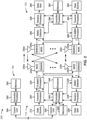
- Fig. 2 shows a block diagram of a design 200 of base station 110 and UE 120, which may be one of the base stations and one of the UEs in Fig. 1 .
- Base station 110 may be equipped with T antennas 234a through 234t
- UE 120 may be equipped with R antennas 252a through 252r, where in general T ⁇ 1 and R ⁇ 1.
- a transmit processor 220 may receive data from a data source 212 for one or more UEs, select one or more modulation and coding schemes (MCS) for each UE based at least in part on channel quality indicators (CQIs) received from the UE, process (e.g., encode and modulate) the data for each UE based at least in part on the MCS(s) selected for the UE, and provide data symbols for all UEs. Transmit processor 220 may also process system information (e.g., for semi-static resource partitioning information (SRPI) and/or the like) and control information (e.g., CQI requests, grants, upper layer signaling, and/or the like) and provide overhead symbols and control symbols.
- MCS modulation and coding schemes
- CQIs channel quality indicators
- Transmit processor 220 may also process system information (e.g., for semi-static resource partitioning information (SRPI) and/or the like) and control information (e.g., CQI requests, grants, upper layer signal
- Transmit processor 220 may also generate reference symbols for reference signals (e.g., the cell-specific reference signal (CRS)) and synchronization signals (e.g., the primary synchronization signal (PSS) and secondary synchronization signal (SSS)).
- a transmit (TX) multiple-input multiple-output (MIMO) processor 230 may perform spatial processing (e.g., precoding) on the data symbols, the control symbols, the overhead symbols, and/or the reference symbols, if applicable, and may provide T output symbol streams to T modulators (MODs) 232a through 232t. Each modulator 232 may process a respective output symbol stream (e.g., for OFDM and/or the like) to obtain an output sample stream.
- Each modulator 232 may further process (e.g., convert to analog, amplify, filter, and upconvert) the output sample stream to obtain a downlink signal.
- T downlink signals from modulators 232a through 232t may be transmitted via T antennas 234a through 234t, respectively.
- the synchronization signals can be generated with location encoding to convey additional information.
- antennas 252a through 252r may receive the downlink signals from base station 110 and/or other base stations and may provide received signals to demodulators (DEMODs) 254a through 254r, respectively.
- Each demodulator 254 may condition (e.g., filter, amplify, downconvert, and digitize) a received signal to obtain input samples.
- Each demodulator 254 may further process the input samples (e.g., for OFDM and/or the like) to obtain received symbols.
- a MIMO detector 256 may obtain received symbols from all R demodulators 254a through 254r, perform MIMO detection on the received symbols if applicable, and provide detected symbols.
- a receive processor 258 may process (e.g., demodulate and decode) the detected symbols, provide decoded data for UE 120 to a data sink 260, and provide decoded control information and system information to a controller/processor 280.
- a channel processor may determine reference signal received power (RSRP), received signal strength indicator (RSSI), reference signal received quality (RSRQ), channel quality indicator (CQI), and/or the like.
- RSRP reference signal received power
- RSSI received signal strength indicator
- RSRQ reference signal received quality indicator
- CQI channel quality indicator
- one or more components of UE 120 may be included in a housing.
- a transmit processor 264 may receive and process data from a data source 262 and control information (e.g., for reports comprising RSRP, RSSI, RSRQ, CQI, and/or the like) from controller/processor 280. Transmit processor 264 may also generate reference symbols for one or more reference signals. The symbols from transmit processor 264 may be precoded by a TX MIMO processor 266 if applicable, further processed by modulators 254a through 254r (e.g., for DFT-s-OFDM, CP-OFDM, and/or the like), and transmitted to base station 110.
- control information e.g., for reports comprising RSRP, RSSI, RSRQ, CQI, and/or the like
- Transmit processor 264 may also generate reference symbols for one or more reference signals.
- the symbols from transmit processor 264 may be precoded by a TX MIMO processor 266 if applicable, further processed by modulators 254a through 254r (e.g., for DFT-
- the uplink signals from UE 120 and other UEs may be received by antennas 234, processed by demodulators 232, detected by a MIMO detector 236 if applicable, and further processed by a receive processor 238 to obtain decoded data and control information sent by UE 120.
- Receive processor 238 may provide the decoded data to a data sink 239 and the decoded control information to controller/processor 240.
- Base station 110 may include communication unit 244 and communicate to network controller 130 via communication unit 244.
- Network controller 130 may include communication unit 294, controller/processor 290, and memory 292.
- Controller/processor 240 of base station 110, controller/processor 280 of UE 120, and/or any other component(s) of Fig. 2 may perform one or more techniques associated with sequence generation to support DMRS multiplexing for pi over 2 BPSK modulation, as described in more detail elsewhere herein.
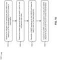
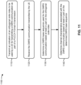
- controller/processor 240 of base station 110, controller/processor 280 of UE 120, and/or any other component(s) of Fig. 2 may perform or direct operations of, for example, process 800 of Fig. 8 , process 900 of Fig. 9 , process 1000 of Fig. 10 , process 1100 of Fig. 11 , and/or other processes as described herein.
- Memories 242 and 282 may store data and program codes for base station 110 and UE 120, respectively.
- a scheduler 246 may schedule UEs for data transmission on the downlink and/or uplink.
- UE 120 may include means for receiving an indication of a DMRS port to be used by the UE 120 for transmitting a DMRS communication; means for determining a base sequence based at least in part on the DMRS port; means for generating a DMRS sequence for the DMRS port based at least in part on the base sequence; means for transmitting the DMRS communication including the DMRS sequence via the DMRS port; and/or the like.
- such means may include one or more components of UE 120 described in connection with Fig. 2 .
- base station 110 may include means for transmitting an indication of a DMRS port to be used by a UE for transmission of one or more DMRS communications; means for receiving a DMRS communication transmitted by the UE using the DMRS port; means for determining a DMRS base sequence used for the DMRS communication based at least in part on the DMRS port; means for determining channel characteristics associated with the DMRS port based at least in part on the DMRS base sequence and the DMRS communication; and/or the like.
- such means may include one or more components of base station 110 described in connection with Fig. 2 .
- Fig. 2 is provided as an example. Other examples may differ from what is described with regard to Fig. 2 .
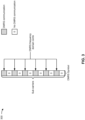
- Fig. 3 is a diagram of an example 300 of a DMRS frequency domain comb, in accordance with various aspects of the present disclosure.
- Some radio access technologies such as New Radio, support pi over 2 (pi/2, or ⁇ /2) binary phase shift keying (BPSK) modulation with discrete Fourier transform (DFT)-spread-orthogonal frequency-division multiplexing (OFDM) (DFT-s-OFDM) for uplink communications.
- BPSK binary phase shift keying
- This modulation scheme provides a lower peak-to-average power ratio (PAPR) for a UE 120 relative to other modulation schemes, such as quadrature phase shift keying (QPSK), quadrature amplitude modulation (QAM), and/or the like.
- QPSK quadrature phase shift keying
- QAM quadrature amplitude modulation
- pi/2 BPSK modulation may result in improved performance for the UE 120, particularly when the UE 120 is located at or near a cell edge, by permitting the UE 120 to transmit an uplink communication with a higher transmit power without violating a maximum power constraint.
- pi/2 BPSK modulation may be used with a DMRS sequence that uses a Zadoff-Chu (ZC) sequence (e.g., with frequency domain spectral shaping (FDSS)) as a base sequence.
- ZC Zadoff-Chu
- FDSS frequency domain spectral shaping
- This may cause link budget loss with regard to a communication link between the UE 120 and a base station 110, and/or may cause a transmit power of the UE 120 to be limited by a DMRS communication rather than a data communication, thereby offsetting the performance issues gained by using pi/2 BPSK modulation.
- a frequency domain comb structure (sometimes referred to as a frequency comb, a frequency domain comb, or similar terminology) may be used for DMRS transmissions (e.g., for transmissions on a physical uplink shared channel (PUSCH)).
- PUSCH physical uplink shared channel
- a UE 120 may transmit DMRS communications on a subset of sub-carriers of a bandwidth, such as by transmitting only on sub-carriers identified using an even index value or only on sub-carriers identified using an odd index value (e.g., even frequency tones or odd frequency tones).
- a time-domain cyclic shift may be applied for DMRS sequences generated using a Zadoff-Chu base sequence.
- this technique cannot be applied to a DMRS sequence transmitted in an uplink transmission that is modulated using pi/2 BPSK modulation because such a DMRS sequence is modulated differently in the frequency domain compared to the ZC-based DMRS sequence (e.g., the ZC-based DMRS sequence has a flat amplitude in the frequency domain whereas the pi/2 BPSK-based DMRS base sequence is a time-domain constant-modulus sequence with a variable amplitude in the frequency domain). Based on this, using a time-domain cyclic shift for a pi/2 BPSK-based DMRS base sequence will not generate orthogonal DMRS sequences.
- UEs 120 may generate orthogonal or quasi-orthogonal DMRS sequences for uplink transmissions that are modulated using pi/2 BPSK modulation. For example, a UE 120 may determine a base sequence for a DMRS sequence based at least in part on a DMRS port assigned to the UE 120 for use by the UE 120 to transmit a DMRS communication. In this way, different DMRS ports (e.g., used by different UEs 120 to transmit DMRS communications) may be associated with different base sequences (e.g., the base sequences may be DMRS port-specific).
- some techniques and apparatuses described herein facilitate use of orthogonal or quasi-orthogonal DMRS ports with pi/2 BPSK modulation. This may permit a UE 120 to transmit uplink communications using pi/2 BPSK modulation with low PAPR for both a data communication and a corresponding DMRS communication. In this way, performance may be improved for the UE 120, particularly when the UE 120 is located at or near a cell edge, by permitting the UE 120 to transmit an uplink communication with a higher transmit power without violating a maximum power constraint. Furthermore, multiple UEs 120 may be permitted to communicate with a base station 110 using the same uplink resource(s), and the base station 110 may distinguish the UEs 120 using corresponding DMRS communications of the UEs 120.
- a time-domain orthogonal cover code may be used to generate orthogonal DMRS sequences for a pi/2 BPSK-based DMRS base sequence.
- OCC time-domain orthogonal cover code
- applying a time-domain OCC to generate orthogonal DMRS sequences may only work for some base sequences, and not all base sequences. For example, when a time-domain OCC is applied to some base sequences, the resulting DMRS sequences may not be orthogonal to the base sequence after passing through a multipath fading channel.
- Some techniques and apparatuses described herein may permit different schemes for generating orthogonal or quasi-orthogonal DMRS sequences to be applied to different base sequences (e.g., a time-domain OCC scheme may be applied to a first base sequence, a cyclic shift may be applied to a second base sequence, and/or the like). This may improve channel estimation performance when a large number of UEs 120 communicate simultaneously to the base station 110, thereby improving spectral efficiency.
- some techniques and apparatuses described herein may be used by UEs 120 in the same cell to generate orthogonal or quasi-orthogonal DMRS sequences using different base sequences (e.g., based at least in part on corresponding DMRS ports assigned to the UEs 120 for use by the UEs 120 for transmitting DMRS communications).
- using different DMRS base sequences for different UEs 120 in the same cell may result in poor performance due to cross-correlation and/or interference issues.
- some techniques and apparatuses described herein overcome these issues due to the manner in which DMRS base sequences are selected and/or generated. Additional details are described below.
- Fig. 3 is provided as an example. Other examples may differ from what is described with regard to Fig. 3 .
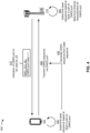
- Fig. 4 is a diagram illustrating an example 400 of sequence generation to support DMRS multiplexing for pi over 2 BPSK modulation, in accordance with various aspects of the present disclosure.
- a base station 110 may transmit, and a UE 120 may receive, an indication of a DMRS port to be used by the UE 120 for transmitting a DMRS communication.
- the DMRS port may be indicated in a signaling message, such as a radio resource control (RRC) message (e.g., an RRC configuration message, an RRC reconfiguration message, and/or the like), downlink control information (DCI), a media access control (MAC) control element (MAC-CE), and/or the like.
- RRC radio resource control
- DCI downlink control information
- MAC-CE media access control element
- the DMRS port may be indicated using a DMRS port index.
- a first DMRS port may be identified using a first DMRS port index value
- a second DMRS port may be identified using a second DMRS port index value
- different DMRS port index values may be assigned to different UEs 120 to permit simultaneous communications by those UEs 120 (e.g., in the same set of time resources or symbols, the same set of frequency resources or sub-carriers, and/or the like).
- the UE 120 may determine a base sequence (sometimes referred to herein as a DMRS base sequence) based at least in part on the DMRS port assigned to the UE 120 for use by the UE 120 to transmit the DMRS communication. As described below, the UE 120 may use the base sequence to generate a DMRS sequence to be transmitted in an uplink communication of the UE 120.
- the base sequence may be a Gold sequence, as described below in more detail in connection with Fig. 5 .
- the base sequence may be a computer-generated sequence, as described in more detail below in connection with Figs. 6 and 7 .
- the UE 120 may generate a DMRS sequence based at least in part on the base sequence. For example, the UE 120 may apply one or more DMRS sequence generation techniques to generate the DMRS sequence from the base sequence (e.g., by applying a cyclic shift to the base sequence, by applying an orthogonal cover code to the base sequence, and/or the like).
- the base sequence e.g., by applying a cyclic shift to the base sequence, by applying an orthogonal cover code to the base sequence, and/or the like.
- the UE 120 may transmit, and the base station 110 may receive, the DMRS sequence via the DMRS port (e.g., an antenna port assigned to the UE 120 and used for DMRS).
- the UE 120 may transmit the DMRS sequence, via the DMRS port, in an uplink transmission.
- the uplink transmission may include the DMRS sequence and an uplink data transmission (e.g., on an uplink data channel, such as a physical uplink shared channel (PUSCH)), or the uplink transmission may include the DMRS sequence and an uplink control transmission (e.g., on an uplink control channel, such as a physical uplink control channel (PUCCH)).
- PUSCH physical uplink shared channel
- PUCCH physical uplink control channel
- the UE 120 may modulate the uplink transmission using pi over two (pi/2) BPSK modulation. For example, the UE 120 may modulate the DMRS sequence and the uplink data transmission using pi/2 BPSK modulation, or the UE 120 may modulate the DMRS sequence and the uplink control transmission using pi/2 BPSK modulation.
- the base station 110 may receive the DMRS communication (e.g., the uplink transmission that includes the DMRS sequence) and may determine a base sequence used for the DMRS communication.
- the base station 110 may determine the base sequence based at least in part on the DMRS port used by the UE 120 for transmitting the DMRS communication.
- the base station 110 may use a mapping rule to determine the base sequence based at least in part on the DMRS port.
- the mapping rule may be a same mapping rule as is used by the UE 120 to generate the base sequence based at least in part on the DMRS port.
- the base station 110 may determine channel characteristics associated with the DMRS port (e.g., the UE 120) based at least in part on the DMRS base sequence and/or the DMRS communication.
- the base station 110 may use the channel characteristics for communications with the UE 120.
- the base station 110 may use the DMRS base sequence and/or the DMRS communication for channel estimation, coherent demodulation, and/or the like.
- the UE 120 may transmit, and the base station 110 may receive, the DMRS sequence (in the uplink transmission) in a same symbol and a same set of sub-carriers (e.g., a same frequency domain comb) as another DMRS sequence transmitted by another UE 120 in a same cell as the UE 120.
- the UE 120 may transmit, and the base station 110 may receive, the DMRS sequence (in the uplink transmission) in a same symbol and a same set of resource blocks, but on a different set of sub-carriers (e.g., a different frequency domain comb), as another DMRS sequence transmitted by another UE 120 in a same cell as the UE 120.
- different (e.g., orthogonal or quasi-orthogonal) DMRS sequences may be transmitted by the different UEs 120 in the same time resource and/or the same set of frequency resources. Because the UEs 120 determine different base sequences depending on a DMRS port assignment, the UEs 120 may generate different DMRS sequences. As a result, the base station 110 may be able to distinguish the DMRS sequences for the different DMRS ports used by the different UEs 120 to transmit DMRS communications.
- Fig. 4 is provided as an example. Other examples may differ from what is described with respect to Fig. 4 .
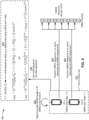
- Fig. 5 is a diagram illustrating an example 500 of sequence generation to support DMRS multiplexing for pi over 2 BPSK modulation, in accordance with various aspects of the present disclosure.
- two UEs 120 located in the same cell may be assigned different DMRS ports.
- a first UE 120 shown as UE A
- a second UE 120 shown as UE B
- a UE 120 may generate a DMRS sequence using a base sequence that depends on the DMRS port index assigned to the UE 120.
- the UE 120 may determine the base sequence based at least in part on the DMRS port index.
- the UE 120 may determine the base sequence based at least in part on whether the DMRS sequence is to be transmitted on an uplink data channel (e.g., the PUSCH) or an uplink control channel (e.g., the PUCCH). Additionally, or alternatively, the UE 120 may determine the base sequence based at least in part on a length of the DMRS (e.g., a number of sub-carriers and/or resource blocks in which the DMRS is to be transmitted), which may depend on a resource allocation assigned to the UE 120.
- a length of the DMRS e.g., a number of sub-carriers and/or resource blocks in which the DMRS is to be transmitted
- the UEs 120 may determine that the DMRS sequence is to be transmitted via the PUSCH, and the UEs 120 may determine that the DMRS length satisfies a threshold (e.g., is greater than or equal to 30). For a DMRS with a longer length, a Gold sequence may have better performance (e.g., than a computer-generated sequence, described below).
- a threshold e.g., is greater than or equal to 30.
- the UEs 120 may determine to use a Gold sequence (e.g., a pi/2 BPSK modulated Gold sequence) as the base sequence for DMRS generation based at least in part on the determination that the DMRS length is greater than or equal to a threshold (e.g., 30) and/or the determination that the DMRS sequence is to be transmitted on the PUSCH.
- a Gold sequence e.g., a pi/2 BPSK modulated Gold sequence
- a UE 120 may generate the Gold sequence (e.g., as the base sequence) using a seed that depends on a DMRS port (e.g., a DMRS port index) assigned to the UE 120.
- a DMRS port e.g., a DMRS port index assigned to the UE 120.
- the first UE 120 may use a DMRS port index of 0 to calculate a first seed for a first Gold sequence to be used as the base sequence for a first DMRS sequence to be transmitted by the first UE 120.
- the second UE 120 may use a DMRS port index of 1 to calculate a second seed for a second Gold sequence to be used as the base sequence for a second DMRS sequence to be transmitted by the second UE 120.
- the UEs 120 may generate different base sequences (e.g., Gold base sequences) for DMRS sequence generation.
- the seed may be generated based at least in part on performing a modulo two operation on a DMRS port index assigned to a UE 120.
- the seed parameter may be a binary value that has a first value (e.g., zero) for a first set of DMRS port indexes (e.g., that have an even value) and that has a second value (e.g., one) for a second set of DMRS port indexes (e.g., that have an odd value).
- a first value e.g., zero
- a second value e.g., one
- a pair of DMRS port indexes that include an even value and an odd value may be scheduled to transmit DMRS on the same frequency domain comb (e.g., in the same symbol and the same set of sub-carriers).
- a first Gold base sequence may be generated for a first DMRS sequence to be transmitted in a frequency domain comb
- a second, orthogonal (or quasi-orthogonal) Gold base sequence may be generated for a second DMRS sequence to be transmitted in the same frequency domain comb.
- the first UE 120 and the second UE 120 may transmit orthogonal or quasi-orthogonal DMRS sequences in the same frequency domain comb (e.g., via a first DMRS port and a second DMRS port, respectively).
- the seed parameter lambda may replace a DMRS scrambling identifier (e.g., n SCID ) in a function or equation used to generate the seed (e.g., c init ).
- a DMRS scrambling identifier e.g., n SCID
- n SCID is received in a DMRS scrambling field in the scheduling DCI.
- lambda is substituted for n SCID , and lambda is calculated as mod(p,2).
- the seed c init may be an integer value between 0 and 2 31 .
- N symb slot may represent the number of symbols per slot
- n s , f ⁇ may represent the slot number within a frame for a sub-carrier spacing configuration (referenced using the symbol mu ( ⁇ ))
- l may represent an OFDM symbol index relative to a reference index (e.g., l may represent an OFDM symbol number within a slot)
- N ID n SCID may represent a scrambling identifier for the UE 120 (e.g., which may depend on a higher layer parameter scramblingID0 and/or scramblingID1 assigned to the UE 120 and/or may equal to be a UE identifier N ID cell depending on certain conditions).
- lambda is multiplied by 2 17 because N ID n SCID includes 16 bits.
- the value of lambda impacts a value of the 17 th bit so as not to alter the value of the UE scrambling identifier N ID n SCID .
- a set of four DMRS ports may each use different seeds (and different Gold base sequences)
- a set of eight DMRS ports may each use different seeds (and different Gold base sequences)
- a set of eight DMRS ports may each use different seeds (and different Gold base sequences)
- the UE 120 may input the value of the seed into a Gold sequence generator of the UE 120 that generates a bit stream based at least in part on the value of the seed (e.g., a first bit c 0 through an N th bit c N , where N is the length of the bit stream).
- the bit stream may be a Gold sequence that is used as a base sequence for DMRS sequence generation.
- the UE 120 may apply one or more sequence generation techniques (e.g., a cyclic shift, an OCC, and/or the like) to the Gold base sequence to generate a DMRS sequence for transmission.
- the first UE 120 and the second UE 120 may generate different DMRS sequences from different Gold base sequences that are generated based at least in part on a respective DMRS port index assigned to the first UE 120 and the second UE 120.
- the first UE 120 may generate a first DMRS sequence (e.g., DMRS sequence A), and may transmit the first DMRS sequence on a DMRS frequency domain comb.
- the second UE 120 e.g., UE B
- may generate a second DMRS sequence e.g., DMRS sequence B
- the first DMRS sequence and the second DMRS sequence may be transmitted in the same symbol and the same set of sub-carriers, as shown.
- the first DMRS sequence and the second DMRS sequence may be transmitted in the same symbol and the same set of resource blocks, but may be transmitted on a different set of sub-carriers (e.g., may be transmitted on different DMRS frequency combs).
- a base station 110 may be capable of distinguishing the first DMRS sequence and the second DMRS sequence (e.g., for different DMRS ports used by the first UE 120 and the second UE 120) despite those DMRS sequences being transmitted in the same time and/or frequency resources.
- Fig. 5 is provided as an example. Other examples may differ from what is described with respect to Fig. 5 .
- Fig. 6 is a diagram illustrating an example 600 of sequence generation to support DMRS multiplexing for pi over 2 BPSK modulation, in accordance with various aspects of the present disclosure.
- a UE 120 may determine a base sequence to be used for DMRS sequence generation based at least in part on a DMRS port index assigned to the UE 120, based at least in part on whether the DMRS sequence is to be transmitted on an uplink data channel or an uplink control channel based at least in part on a length of the DMRS, and/or the like.
- the UEs 120 may determine that the DMRS sequence is to be transmitted via the PUSCH, and the UEs 120 may determine that the DMRS length does not satisfy a threshold (e.g., is less than 30). For a DMRS with a shorter length, a computer-generated sequence may have better performance (e.g., than a Gold sequence, described above). Thus, as shown by reference number 630, the UEs 120 may determine to use a computer-generated sequence (CGS) as the base sequence for DMRS generation based at least in part on the determination that the DMRS length is less than a threshold (e.g., 30) and/or the determination that the DMRS sequence is to be transmitted on the PUSCH.
- a threshold e.g., 30
- the CGS may be selected from a table that is stored by the UE 120.
- the UE 120 may identify a table from which the CGS is to be selected based at least in part on the determination that the DMRS length is less than a threshold (e.g., 30) and/or the determination that the DMRS sequence is to be transmitted on the PUSCH. Additionally, or alternatively, the UE 120 may identify a table from which the CGS is to be selected based at least in part on the DMRS length.
- the UE 120 may store different tables to be used for different DMRS lengths (e.g., a first table for DMRS length 6, a second table for DMRS length 12, a third table for DMRS length 18, a fourth table for DMRS length 24, and/or the like), and the UE 120 may select a table that corresponds to a DMRS length for a DMRS sequence to be transmitted by the UE 120.
- a first table for DMRS length 6 e.g., a first table for DMRS length 6, a second table for DMRS length 12, a third table for DMRS length 18, a fourth table for DMRS length 24, and/or the like
- the UE 120 may select a table that corresponds to a DMRS length for a DMRS sequence to be transmitted by the UE 120.
- the table may indicate relationships between CGS group indexes and corresponding CGS groups.
- each CGS group index may correspond to a CGS group.
- the table may store 30 CGS indexes (shown as 0 through 29) corresponding to 30 CGS groups.
- a CGS group may include a pair of CGSs (e.g., each CGS group may include exactly two CGSs).
- a first CGS group represented by a CGS group index of 0, may include a first pair of CGSs (e.g., shown as s 0 and ⁇ 0 )
- a second CGS group represented by a CGS group index of 1
- a second pair of CGSs e.g., shown as s 1 and ⁇ 1
- so on e.g., through a thirtieth CGS group, represented by a CGS group index of 29.
- a UE 120 may select a CGS, to be used as a base sequence, based at least in part on a group index determined by the UE 120 and a DMRS port index assigned to the UE 120, as described below.
- the DMRS port index may be signaled to the UE 120 in a signaling message, such as an RRC message, a DCI message, and/or the like.
- n ID RS may represent an identifier configured for the UE 120 by the base station 110 (e.g., which may be equal to either n ID PUSCH or n ID cell depending on whether a higher layer parameter nPUSCH Identity is configured for the UE 120), c may represent a random sequence used to generate a random number f gh between 0 and 29, and the other variables may represent values as described above in connection with Fig. 5 .
- the UE 120 may use a value of the calculated sequence identifier ( seq id ) to select one of the CGSs included in the pair of CGSs. For example, if the sequence identifier has a first value (e.g., 0), then the UE 120 may select a first CGS (e.g., s u ) included in the pair of CGSs. Similarly, if the sequence identifier has a second value (e.g., 1), then the UE 120 may select a second CGS (e.g., ⁇ u ) included in the pair of CGSs.
- a first value e.g., 0
- the UE 120 may select a first CGS (e.g., s u ) included in the pair of CGSs.
- a second value e.g., 1
- the sequence identifier may be a binary value that has a first value (e.g., zero) for a first set of DMRS port indexes (e.g., that have an even value) and that has a second value (e.g., one) for a second set of DMRS port indexes (e.g., that have an odd value).
- a first value e.g., zero
- a second value e.g., one
- a pair of DMRS port indexes that include an even value and an odd value may be scheduled to transmit DMRS on the same frequency domain comb (e.g., in the same symbol and the same set of sub-carriers).
- a first CGS base sequence may be generated for a first DMRS sequence to be transmitted in a frequency domain comb
- a second, orthogonal (or quasi-orthogonal) CGS base sequence may be generated for a second DMRS sequence to be transmitted in the same frequency domain comb.
- the first UE 120 and the second UE 120 may transmit orthogonal or quasi-orthogonal DMRS sequences in the same frequency domain comb (e.g., via a first DMRS port and a second DMRS port, respectively).
- the table may be populated with CGSs such that a first CGS base sequence and a second CGS base sequence, included in the same pair of CGSs (e.g., the same CGS group), are orthogonal or quasi-orthogonal to one another.
- Two sequences that are orthogonal to one another may have a cross-correlation of zero, and two sequences that are quasi-orthogonal to one another may have a cross-correlation that is less than or equal to a threshold (e.g., a first cross-correlation threshold ⁇ 1 ).
- a CGS group may include two CGSs that are orthogonal to one another.
- a CGS group may include two CGSs that are quasi-orthogonal to one another.
- each CGS group included in the table includes two CGSs that are orthogonal or quasi-orthogonal with one another. In this way, different UEs 120 assigned to transmit DMRS on the same set of resources may use orthogonal or quasi-orthogonal base sequences to generate a DMRS sequence for transmission.
- the table may be populated with CGSs such that a cross-correlation between any two CGSs included in the table (e.g., included in any one of the CGS groups) is less than or equal to a threshold (e.g., a second cross-correlation threshold ⁇ 2 ).
- a threshold e.g., a second cross-correlation threshold ⁇ 2
- the second cross-correlation threshold ⁇ 2 may be greater than or equal to the first cross-correlation threshold ⁇ 1 . In this way, inter-cell interference may be reduced for UEs 120 that transmit different DMRS sequences in different cells.
- the table may be populated with CGSs such that each CGS included in the table (e.g., included in any one of the CGS groups) has a PAPR that is less than or equal to a PAPR threshold.
- each CGS included in the table e.g., included in any one of the CGS groups
- a PAPR threshold e.g., the benefits of pi/2 BPSK modulation, which results in a low PAPR as described above, may be realized (e.g., may not be offset by using a DMRS sequence with a high PAPR).
- the table may be populated with CGSs (e.g., CGS base sequences) such that every pair of cyclic-shifted sequences, capable of being generated from the CGS base sequences, are orthogonal or quasi-orthogonal with one another (e.g., have cross-correlations that are less than or equal to one or more of the thresholds described above). Additionally, or alternatively, the table may be populated with CGSs (e.g., CGS base sequences) such that every cyclic-shift sequence, capable of being generated from the CGS base sequences, has a PAPR that is less than or equal to the PAPR threshold described above. In this way, the base sequences and the DMRS sequences that are generated from the base sequences may be distinguishable and/or may assist with realizing the benefits of pi/2 BPSK modulation, as described above.
- CGSs e.g., CGS base sequences
- the CGS may be selected from a table that is stored by the UE 120. Additionally or alternatively to the various aspects of the table described above, the table may not include a pair of sequences per "group" index. Rather, a "group” as described above may comprise a single sequence, such that the table comprises, for example, a first CGS (e.g., s 0 ), represented by CGS index ( u ) 0, a second CGS (e.g., s 1 ), represented by CGS index 1, and so on (e.g., through a thirtieth CGS, represented by a CGS index of 29).
- a first CGS e.g., s 0
- CGS index ( u ) e.g., s 1
- CGS index 1 e.g., through a thirtieth CGS, represented by a CGS index of 29.
- a UE 120 may select a CGS, to be used as a base sequence, based at least in part on the CGS index (instead of a CGS group index).
- the CGS index may be determined by the UE 120 using the DMRS port index assigned to the UE 120, as described below.
- the DMRS port index can be used to determine the CGS index where a single sequence is associated with each CGS index in the table. While in the example discussed further above, the CGS group index was determined without reference to DMRS port, but the DMRS port was then used to determine the sequences of the group/pair of sequences associated with the CGS group index.
- the sequence identifier (which depended on the DMRS port index p ) described further above for use in determining which sequence of the pair of sequences in the CGS group to select may be used to determine the CGS index.
- the UE 120 may use a value of the calculated sequence identifier ( seq id ) to determine a CGS index ( u ) in order to identify the sequence to be used in the table of CGSs.
- the variables may represent values as described above in connection with Fig. 5 and elsewhere in Fig. 6 .
- the first UE 120 may generate a first DMRS sequence (e.g., DMRS sequence A), and may transmit the first DMRS sequence on a DMRS frequency domain comb.
- the second UE 120 e.g., UE B
- may generate a second DMRS sequence e.g., DMRS sequence B
- the first DMRS sequence and the second DMRS sequence may be transmitted in the same symbol and the same set of sub-carriers, as shown.
- the first DMRS sequence and the second DMRS sequence may be transmitted in the same symbol and the same set of resource blocks, but may be transmitted on a different set of sub-carriers (e.g., may be transmitted on different DMRS frequency combs).
- the first DMRS sequence and the second DMRS sequence may be orthogonal or quasi-orthogonal to one another.
- a base station 110 may be capable of distinguishing the first DMRS sequence and the second DMRS sequence (e.g., for different DMRS ports used by the first UE 120 and the second UE 120) despite those DMRS sequences being transmitted in the same time and/or frequency resources.
- first DMRS sequence and the second DMRS sequence may not be orthogonal and/or may not be quasi-orthogonal to each other.
- Fig. 6 is provided as an example. Other examples may differ from what is described with respect to Fig. 6 .
- Fig. 7 is a diagram illustrating an example 700 of sequence generation to support DMRS multiplexing for pi over 2 BPSK modulation, in accordance with various aspects of the present disclosure.
- two UEs 120 located in the same cell may be assigned different DMRS ports, as described above.
- a UE 120 may determine a base sequence to be used for DMRS sequence generation based at least in part on a DMRS port index assigned to the UE 120, based at least in part on whether the DMRS sequence is to be transmitted on an uplink data channel or an uplink control channel based at least in part on a length of the DMRS, and/or the like.
- the UEs 120 may determine that the DMRS sequence is to be transmitted via the PUCCH.
- the PUCCH e.g., PUCCH format 4, which supports transmissions from multiple UEs 120 on the same set of frequency resources
- the PUCCH may have a fixed DMRS length (e.g., a fixed DMRS length of 12 resource blocks).
- the PUCCH may have PUCCH format 3 (e.g., without UE multiplexing) or PUCCH format 4 (e.g., with UE multiplexing).
- a computer-generated sequence may have better performance (e.g., than a Gold sequence, described above).
- the UEs 120 may determine to use a CGS as the base sequence for DMRS generation based at least in part on the determination that the DMRS sequence is to be transmitted on the PUCCH (e.g., and/or a determination that the DMRS length is less than a threshold (e.g., 30)).
- a threshold e.g., 30
- the CGS may be selected from a table that is stored by the UE 120.
- the UE 120 may identify a table from which the CGS is to be selected based at least in part on the determination that the DMRS sequence is to be transmitted on the PUCCH.
- the UE 120 may store different tables to be used for base sequence determination for the PUSCH and for the PUCCH, and the UE 120 may select a table based at least in part on whether a DMRS sequence, to be generated using the base sequence, is to be transmitted on the PUSCH or the PUCCH.
- the same table may be used for PUCCH format 3 and PUCCH format 4.
- different CGS tables may be used for the PUSCH and the PUCCH regardless of a length of the DMRS.
- different tables may be used for the PUSCH and the PUCCH for different DMRS lengths, and different tables may be used for the PUSCH and the PUCCH for the same DMRS length.
- a first table may be used for the PUSCH, and a second, different table may be used for the PUCCH.
- DMRS for the PUCCH has a different structure than DMRS for the PUSCH (e.g., because PUSCH DMRS has a frequency domain comb 2 structure, and because the PUCCH DMRS does not have a frequency domain comb 2 structure), performance may be improved by using separate tables of base sequences, which may be optimized or configured to improve performance depending on the DMRS structure.
- the table may indicate relationships between CGS group indexes and corresponding CGS groups.
- each CGS group index may correspond to a CGS group.
- the table may store 30 CGS indexes (shown as 0 through 29) corresponding to 30 CGS groups.
- a CGS group may include four CGSs (e.g., each CGS group may include exactly four CGSs).
- a first CGS group represented by a CGS group index of 0, may include a first group of four CGSs (e.g., shown as s 0 , 0 , s 0 , 1 , s 0 , 2 , and s 0 , 3 ), a second CGS group, represented by a CGS group index of 1, may include a second group of four CGSs (e.g., shown as s 1 , 0 , s 1 , 1 , s 1 , 2 , and s 1 , 3 ), and so on (e.g., through a thirtieth CGS group, represented by a CGS group index of 29).
- a UE 120 may select a CGS, to be used as a base sequence, based at least in part on a group index determined by the UE 120 and an orthogonal code index assigned to the UE 120, as described below.
- the orthogonal code index may be signaled to the UE 120 in a signaling message, such as an RRC message and/or the like.
- a UE 120 may determine a group index (e.g., a CGS group index) using a pseudo-randomly determined value (e.g., between 0 and 29). For example, the UE 120 may determine a CGS group index u as described above in connection with Fig. 6 with reference to a table having pairs of sequences associated with each CGS group index. An alternative method of determining the CGS index is described further below.
- a group index e.g., a CGS group index
- pseudo-randomly determined value e.g., between 0 and 29.
- the UE 120 may select a CGS (e.g., as a base sequence), from the set of CGSs, based at least in part on an orthogonal code index assigned to the UE 120 by the base station 110. For example, the UE 120 may determine a sequence identifier (shown as DMRS sequence ID) that corresponds to the orthogonal code index. As shown by reference number 770, in some aspects, the UE 120 may store a table that indicates relationships between orthogonal code indexes and corresponding sequence identifiers.
- a first orthogonal code index (e.g., with a value of 0) may correspond to a first sequence identifier (e.g., with a value of 0)
- a second orthogonal code index (e.g., with a value of 1) may correspond to a second sequence identifier (e.g., with a value of 1)
- a third orthogonal code index (e.g., with a value of 2) may correspond to a third sequence identifier (e.g., with a value of 2)
- a fourth orthogonal code index (e.g., with a value of 3) may correspond to a fourth sequence identifier (e.g., with a value of 3).
- the UE 120 may use a value of the determined sequence identifier to select one of the CGSs included in the CGS group (e.g., a group of four CGSs). For example, the UE 120 may select a first CGS (e.g., s 0,0 ) included in the CGS group when the sequence identifier has a first value (e.g., 0), the UE 120 may select a second CGS (e.g., s 0,1 ) included in the CGS group when the sequence identifier has a second value (e.g., 1), the UE 120 may select a third CGS (e.g., s 0,2 ) included in the CGS group when the sequence identifier has a third value (e.g., 2), and the UE 120 may select a fourth CGS (e.g., s 0,3 ) included in the CGS group when the sequence identifier has a fourth value (e.g., 3).
- a first CGS e.g.
- the sequence identifier may be two bits, capable of having four different values.
- the sequence identifier may have a first value (e.g., zero) for a first set of DMRS port indexes, may have a second value (e.g., one) for a second set of DMRS port indexes, may have a third value (e.g., two) for a third set of DMRS port indexes, and may have a fourth value (e.g., three) for a fourth set of DMRS port indexes.
- the PUCCH may support four simultaneous DMRS transmissions (e.g., from four UEs 120 and/or four DMRS ports) on the same uplink resource.
- four different (e.g., orthogonal or quasi-orthogonal) CGS base sequences may be generated for a corresponding four DMRS sequences to be transmitted in the same uplink resource.
- up to four UEs 120 may transmit orthogonal or quasi-orthogonal DMRS sequences in the same uplink resource (e.g., via a first, second, third, and fourth DMRS port).
- the table may be populated with CGSs such that a first CGS base sequence, a second CGS base sequence, a third CGS base sequence, and a fourth CGS base sequence, included in the same CGS group (e.g., the same group of four CGSs), are orthogonal or quasi-orthogonal with one another.
- a CGS group may include four CGSs that are orthogonal to one another.
- a CGS group may include four CGSs that are quasi-orthogonal to one another.
- each CGS group, included in the table includes four CGSs that are orthogonal or quasi-orthogonal with one another. In this way, different UEs 120 assigned to transmit DMRS on the same set of resources may use orthogonal or quasi-orthogonal base sequences to generate a DMRS sequence for transmission.
- the table may be populated with CGSs such that a cross-correlation between any two CGSs, included in the table (e.g., included in any one of the CGS groups), is less than or equal to a threshold (e.g., a second cross-correlation threshold ⁇ 2 ).
- a threshold e.g., a second cross-correlation threshold ⁇ 2
- the second cross-correlation threshold ⁇ 2 may be greater than or equal to the first cross-correlation threshold ⁇ 1 . In this way, inter-cell interference may be reduced for UEs 120 that transmit different DMRS sequences in different cells.
- the table may be populated with CGSs such that each CGS included in the table (e.g., included in any one of the CGS groups) has a PAPR that is less than or equal to a PAPR threshold.
- each CGS included in the table e.g., included in any one of the CGS groups
- a PAPR threshold e.g., the benefits of pi/2 BPSK modulation, which results in a low PAPR as described above, may be realized (e.g., may not be offset by using a DMRS sequence with a high PAPR).
- the table may be populated with CGSs (e.g., CGS base sequences) such that every pair of cyclic-shifted sequences, capable of being generated from the CGS base sequences, are orthogonal or quasi-orthogonal with one another (e.g., have cross-correlations that are less than or equal to one or more of the thresholds described above). Additionally, or alternatively, the table may be populated with CGSs (e.g., CGS base sequences) such that every cyclic-shift sequence, capable of being generated from the CGS base sequences, has a PAPR that is less than or equal to the PAPR threshold described above. In this way, the base sequences and the DMRS sequences that are generated from the base sequences may be distinguishable and/or may assist with realizing the benefits of pi/2 BPSK modulation, as described above.
- CGSs e.g., CGS base sequences
- the CGS may be selected from a table that is stored by the UE 120. Additionally or alternatively to the various aspects of the table described above, the table may not include a group of four sequences per "group" index. Rather, a "group” as described above may comprise a single sequence, such that the table comprises, for example, a first CGS (e.g., s 0 ) , represented by CGS index ( u ) 0, a second CGS (e.g., s 1 ), represented by CGS index 1, and so on (e.g., through a thirtieth CGS, represented by a CGS index of 29).
- a first CGS e.g., s 0
- CGS index u
- s 1 represented by CGS index 1
- CGS index 1 e.g., through a thirtieth CGS, represented by a CGS index of 29.
- a UE 120 may select a CGS, to be used as a base sequence, based at least in part on the CGS index (instead of a CGS group index).
- the CGS index may be determined by the UE 120 using the orthogonal code index assigned to the UE 120, as described below.
- the orthogonal code index can be used to determine the CGS index where a single sequence is associated with each CGS index in the table.
- the CGS group index was determined without reference to an orthogonal code index, but the orthogonal code index was then used to determine the sequences of the group of sequences (e.g., group of four) associated with the CGS group index.
- the orthogonal code index described further above for use in determining which sequence of the group of sequences in the CGS group to select may be used to determine the CGS index.
- the UE 120 may use the orthogonal code index signaled to the UE in order to identify the sequence to be used in the table of CGSs.
- f ss n ID mod 30 and n hop can represent a frequency hop index, while other the variables may represent values as described above in connection with Fig. 5 and elsewhere in Fig. 6 .
- the frequency hop index is used since, for PUCCH, DMRS sequence is hopped on a per frequency hop basis. It is understood that this is in contrast with DMRS transmission over PUSCH because in PUSCH, the DMRS sequence is hopped on a per OFDM symbol basis.
- the first UE 120 may generate a first DMRS sequence (e.g., DMRS sequence A), and may transmit the first DMRS sequence on an uplink resource (e.g., a time resource, a frequency resource, a spatial resource, and/or the like).
- the second UE 120 e.g., UE B
- may generate a second DMRS sequence e.g., DMRS sequence B
- the first DMRS sequence and the second DMRS sequence may be transmitted in the same symbol and the same set of resource blocks (e.g., on all sub-carriers, since the PUCCH may not use a frequency domain comb structure).
- the techniques described above may support up to two additional UEs 120 (e.g., a third UE 120 and a fourth UE 120) that transmit DMRS sequences on the PUCCH in the same time and/or frequency resources as the first UE 120 and the second UE 120.
- the first DMRS sequence and the second DMRS sequence may be orthogonal or quasi-orthogonal to one another.
- a base station 110 may be capable of distinguishing the DMRS sequences (e.g., for different DMRS ports and/or different UEs 120) despite those DMRS sequences being transmitted in the same time and/or frequency resources.
- the first DMRS sequence and the second DMRS sequence may not be orthogonal and/or may not be quasi-orthogonal to each other.
- Fig. 7 is provided as an example. Other examples may differ from what is described with respect to Fig. 7 .
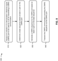
- Fig. 8 is a diagram illustrating an example process 800 performed, for example, by a UE, in accordance with various aspects of the present disclosure.
- Example process 800 is an example where a UE (e.g., UE 120 and/or the like) performs operations associated with sequence generation to support DMRS multiplexing for pi over 2 BPSK modulation.
- a UE e.g., UE 120 and/or the like
- process 800 may include receiving an indication of a demodulation reference signal (DMRS) port to be used by the UE for transmitting a DMRS communication (block 810).
- the UE e.g., using antenna 252, DEMOD 254, MIMO detector 256, receive processor 258, controller/processor 280, and/or the like
- process 800 may include determining a base sequence based at least in part on the DMRS port (block 820).
- the UE e.g., using controller/processor 280 and/or the like
- process 800 may include generating a DMRS sequence for the DMRS port based at least in part on the base sequence (block 830).
- the UE e.g., using controller/processor 280 and/or the like
- process 800 may include transmitting the DMRS communication including the DMRS sequence via the DMRS port (block 840).
- the UE e.g., using controller/processor 280, transmit processor 264, TX MIMO processor 266, MOD 254, antenna 252, and/or the like
- Process 800 may include additional aspects, such as any single aspect or any combination of aspects described below and/or in connection with one or more other processes described elsewhere herein.
- the DMRS communication is transmitted in a same symbol and a same set of sub-carriers as another DMRS communication transmitted by another UE in a same cell as the UE.
- the DMRS communication is transmitted in a same symbol and a same set of resource blocks, but on a different set of sub-carriers, as another DMRS communication transmitted by another UE in a same cell as the UE.
- the DMRS communication is transmitted in an uplink transmission that is modulated using pi over two binary phase shift keying modulation.
- the base sequence is a Gold sequence generated using a seed that is determined based at least in part on the DMRS port.
- the Gold sequence is determined based at least in part on at least one of: a determination that a DMRS length is greater than or equal to a threshold, a determination that the DMRS communication is to be transmitted on a physical uplink shared channel (PUSCH), or, a combination thereof.
- PUSCH physical uplink shared channel
- the seed is generated based at least in part on performing a modulo two operation on a DMRS port index of the DMRS port.
- the base sequence is a computer-generated sequence selected from a table, stored by the UE, based at least in part on a group index, determined by the UE, and the DMRS port.
- the computer-generated sequence is selected from the table based at least in part on: determining a pair of computer-generated sequences that correspond to the group index, and selecting the computer-generated sequence from the pair of computer-generated sequences based at least in part on performing a modulo two operation on a DMRS port index of the DMRS port.
- the computer-generated sequence is selected based at least in part on at least one of: a determination that a DMRS length is less than or equal to a threshold, a determination that the DMRS communication is for a physical uplink shared channel (PUSCH), or a combination thereof.
- the table is selected from a plurality of tables based at least in part on a DMRS length.
- the group index corresponds to a computer-generated sequence group.
- the computer-generated sequence is included in the computer-generated sequence group.
- the table indicates relationships between a plurality of group indexes and a corresponding plurality of computer-generated sequence groups.
- each of the plurality of computer-generated sequences groups includes two computer-generated sequences.
- each computer-generated sequence group, included in the plurality of computer-generated sequence groups includes two computer-generated sequences that are orthogonal or quasi-orthogonal with one another.
- a cross-correlation between every two computer-generated sequences, included in the plurality of computer-generated sequence groups is less than or equal to a threshold.
- each computer-generated sequence, in the plurality of computer-generated sequence groups has a peak-to-average power ratio (PAPR) that is less than or equal to a PAPR threshold.
- PAPR peak-to-average power ratio
- the base sequence is a computer-generated sequence selected from a table, stored by the UE, based at least in part on a group index, determined by the UE, and an orthogonal code index signaled to the UE.
- the computer-generated sequence is selected from the table based at least in part on determining a computer-generated sequence group that corresponds to the group index, and selecting the computer-generated sequence from the computer-generated sequence group based at least in part on the orthogonal code index.
- the computer-generated sequence is selected based at least in part on a determination that the DMRS communication is for a physical uplink control channel (PUCCH).
- PUCCH physical uplink control channel
- the PUCCH is PUCCH format 3 or PUCCH format 4.
- the group index corresponds to a computer-generated sequence group.
- the computer-generated sequence is included in the computer-generated sequence group.
- the table indicates relationships between a plurality of group indexes and a corresponding plurality of computer-generated sequence groups.
- each of the plurality of computer-generated sequence groups includes four computer-generated sequences.
- each computer-generated sequence group, included in the plurality of computer-generated sequence groups includes four computer-generated sequences that are orthogonal or quasi-orthogonal with one another.
- a cross-correlation between every two computer-generated sequences, included in the plurality of computer-generated sequence groups is less than or equal to a threshold.
- each computer-generated sequence, in the plurality of computer-generated sequence groups has a peak-to-average power ratio (PAPR) that is less than or equal to a PAPR threshold.
- PAPR peak-to-average power ratio
- the base sequence is a computer-generated sequence selected from a table, of a plurality of tables, identified based at least in part on whether the DMRS communication is for a physical uplink shared channel (PUSCH) or a physical uplink control channel (PUCCH).
- PUSCH physical uplink shared channel
- PUCCH physical uplink control channel
- process 800 may include additional blocks, fewer blocks, different blocks, or differently arranged blocks than those depicted in Fig. 8 . Additionally, or alternatively, two or more of the blocks of process 800 may be performed in parallel.
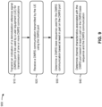
- Fig. 9 is a diagram illustrating an example process 900 performed, for example, by a base station, in accordance with various aspects of the present disclosure.
- Example process 900 is an example where a base station (e.g., base station 110 and/or the like) performs operations associated with sequence generation to support DMRS multiplexing for pi over 2 BPSK modulation.
- a base station e.g., base station 110 and/or the like
- process 900 may include transmitting an indication of a demodulation reference signal (DMRS) port to be used by a user equipment (UE) for transmission of one or more DMRS communications (block 910).
- the base station e.g., using controller/processor 240, transmit processor 220, TX MIMO processor 230, MOD 232, antenna 234, and/or the like
- process 900 may include receiving, at the base station, a DMRS communication transmitted by the UE using the DMRS port (block 920).
- the base station e.g., using antenna 234, DEMOD 232, MIMO detector 236, receive processor 238, controller/processor 240, and/or the like
- process 900 may include determining a DMRS base sequence used for the DMRS communication based at least in part on the DMRS port (block 930).
- the base station e.g., using controller/processor 240 and/or the like
- process 900 may include determining channel characteristics associated with the DMRS port based at least in part on the DMRS base sequence and the DMRS communication (block 940).
- the base station e.g., using controller/processor 240 and/or the like
- Process 900 may include additional aspects, such as any single aspect or any combination of aspects described below and/or in connection with one or more other processes described elsewhere herein.
- the DMRS communication is received in a same symbol and a same set of sub-carriers as another DMRS communication received from another UE in a same cell as the UE.
- the DMRS communication is received in a same symbol and a same set of resource blocks, but on a different set of sub-carriers, as another DMRS communication received from another UE in a same cell as the UE.
- the DMRS communication is received in an uplink communication that is modulated using pi over two binary phase shift keying modulation.
- the DMRS base sequence is a Gold sequence determined using a seed that is determined based at least in part on the DMRS port.
- the Gold sequence is determined based at least in part on at least one of: a determination that a DMRS length is greater than or equal to a threshold, a determination that the DMRS communication is received on a physical uplink shared channel (PUSCH), or a combination thereof.
- PUSCH physical uplink shared channel
- the seed is generated based at least in part on performing a modulo two operation on a DMRS port index of the DMRS port.
- the DMRS base sequence is a computer-generated sequence selected from a table, stored by the base station, based at least in part on a group index, determined by the base station, and the DMRS port.
- the computer-generated sequence is selected from the table based at least in part on determining a pair of computer-generated sequences that correspond to the group index, and selecting the computer-generated sequence from the pair of computer-generated sequences based at least in part on performing a modulo two operation on a DMRS port index of the DMRS port.
- the computer-generated sequence is selected based at least in part on at least one of: a determination that a DMRS length is less than or equal to a threshold, a determination that the DMRS communication is received on a physical uplink shared channel (PUSCH), or a combination thereof.
- a DMRS length is less than or equal to a threshold
- PUSCH physical uplink shared channel
- the table is selected from a plurality of tables based at least in part on a DMRS length.
- the group index corresponds to a computer-generated sequence group.
- the computer-generated sequence is included in the computer-generated sequence group.
- the table indicates relationships between a plurality of group indexes and a corresponding plurality of computer-generated sequence groups.
- each of the plurality of computer-generated sequences groups includes two computer-generated sequences.
- each computer-generated sequence group, included in the plurality of computer-generated sequence groups includes two computer-generated sequences that are orthogonal or quasi-orthogonal with one another.
- a cross-correlation between every two computer-generated sequences, included in the plurality of computer-generated sequence groups is less than or equal to a threshold.
- each computer-generated sequence, in the plurality of computer-generated sequence groups has a peak-to-average power ratio (PAPR) that is less than or equal to a PAPR threshold.
- PAPR peak-to-average power ratio
- the DMRS base sequence is a computer-generated sequence selected from a table, stored by the base station, based at least in part on a group index, determined by the base station, and an orthogonal code index signaled to the UE.
- the computer-generated sequence is selected from the table based at least in part on determining a computer-generated sequence group that corresponds to the group index, and selecting the computer-generated sequence from the computer-generated sequence group based at least in part on the orthogonal code index.
- the computer-generated sequence is selected based at least in part on a determination that the DMRS communication is received on a physical uplink control channel (PUCCH).
- PUCCH physical uplink control channel
- the PUCCH is PUCCH format 3 or PUCCH format 4.
- the group index corresponds to a computer-generated sequence group.
- the computer-generated sequence is included in the computer-generated sequence group.
- the table indicates relationships between a plurality of group indexes and a corresponding plurality of computer-generated sequence groups.
- each of the plurality of computer-generated sequence groups includes four computer-generated sequences.
- each computer-generated sequence group, included in the plurality of computer-generated sequence groups includes four computer-generated sequences that are orthogonal or quasi-orthogonal with one another.
- a cross-correlation between every two computer-generated sequences, included in the plurality of computer-generated sequence groups is less than or equal to a threshold.
- each computer-generated sequence, in the plurality of computer-generated sequence groups has a peak-to-average power ratio (PAPR) that is less than or equal to a PAPR threshold.
- PAPR peak-to-average power ratio
- the base sequence is a computer-generated sequence selected from a table, of a plurality of tables, identified based at least in part on whether the DMRS communication is for a physical uplink shared channel (PUSCH) or a physical uplink control channel (PUCCH).
- PUSCH physical uplink shared channel
- PUCCH physical uplink control channel
- process 900 may include additional blocks, fewer blocks, different blocks, or differently arranged blocks than those depicted in Fig. 9 . Additionally, or alternatively, two or more of the blocks of process 900 may be performed in parallel.
- Fig. 10 is a diagram illustrating an example process 1000 performed, for example, by a UE, in accordance with various aspects of the present disclosure.
- Example process 1000 is an example where the UE (e.g., UE 120 and/or the like) performs operations associated with sequence generation to support DMRS multiplexing for pi over 2 BPSK modulation.
- the UE e.g., UE 120 and/or the like
- process 1000 may include receiving an indication of an orthogonal code index to be used by the UE for transmitting a physical uplink control channel (PUCCH) Format 4 transmission (block 1010).
- the UE e.g., using receive processor 258, controller/processor 280, memory 282, and/or the like
- process 1000 may include determining a base sequence based at least in part on the orthogonal code index (block 1020).
- the UE e.g., using receive processor 258, transmit processor 264, controller/processor 280, memory 282, and/or the like
- process 1000 may include generating a DMRS sequence based at least in part on the base sequence (block 1030).
- the UE e.g., using receive processor 258, transmit processor 264, controller/processor 280, memory 282, and/or the like
- process 1000 may include transmitting the DMRS communication including the DMRS sequence as part of the PUCCH Format 4 transmission (block 1040).
- the UE e.g., using transmit processor 264, controller/processor 280, memory 282, and/or the like
- Process 1000 may include additional aspects, such as any single aspect or any combination of aspects described below and/or in connection with one or more other processes described elsewhere herein.
- determining the base sequence based at least in part on the orthogonal code index comprises: determining an index based at least in part on the orthogonal code index; and selecting a computer-generated sequence from a table, stored by the UE, using the index.
- the base sequence is a computer-generated sequence selected based at least in part on a determination that the DMRS communication is for the PUCCH.
- the base sequence is a computer-generated sequence selected from a table, of a plurality of tables, identified based at least in part on whether the DMRS communication is for a PUSCH or a PUCCH.
- process 1000 may include additional blocks, fewer blocks, different blocks, or differently arranged blocks than those depicted in Fig. 10 . Additionally, or alternatively, two or more of the blocks of process 1000 may be performed in parallel.
- Fig. 11 is a diagram illustrating an example process 1100 performed, for example, by a base station, in accordance with various aspects of the present disclosure.
- Example process 1100 is an example where the base station (e.g., base station 110 and/or the like) performs operations associated with sequence generation to support DMRS multiplexing for pi over 2 BPSK modulation.
- the base station e.g., base station 110 and/or the like
- process 1100 may include transmitting an indication of an orthogonal code index to be used by a UE for transmitting a DMRS communication as part of a PUCCH Format 4 transmission (block 1110).
- the base station e.g., using transmit processor 220, controller/processor 240, memory 242, and/or the like
- process 1100 may include receiving the DMRS communication transmitted by the UE (block 1120).
- the base station e.g., using receive processor 238, controller/processor 240, memory 242, and/or the like
- process 1100 may include determining a DMRS base sequence used for the DMRS communication based at least in part on the orthogonal code index (block 1130).
- the base station e.g., using transmit processor 220, receive processor 238, controller/processor 240, memory 242, and/or the like
- process 1100 may include determining channel characteristics associated with the DMRS communication based at least in part on the determined DMRS base sequence (block 1140).
- the base station e.g., using transmit processor 220, receive processor 238, controller/processor 240, memory 242, and/or the like
- Process 1100 may include additional aspects, such as any single aspect or any combination of aspects described below and/or in connection with one or more other processes described elsewhere herein.
- determining the DMRS base sequence used for the DMRS communication based at least in part on the orthogonal code index comprises: determining an index based at least in part on the orthogonal code index; and selecting a computer-generated sequence from a table, stored by the base station, using the index.
- the base sequence is a computer-generated sequence selected based at least in part on a determination that the DMRS communication is for the PUCCH.
- the base sequence is a computer-generated sequence selected from a table, of a plurality of tables, identified based at least in part on whether the DMRS communication is for a PUSCH or a PUCCH.
- process 1100 may include additional blocks, fewer blocks, different blocks, or differently arranged blocks than those depicted in Fig. 11 . Additionally, or alternatively, two or more of the blocks of process 1100 may be performed in parallel.
- ком ⁇ онент is intended to be broadly construed as hardware, firmware, and/or a combination of hardware and software.
- a processor is implemented in hardware, firmware, and/or a combination of hardware and software.
- satisfying a threshold may refer to a value being greater than the threshold, greater than or equal to the threshold, less than the threshold, less than or equal to the threshold, equal to the threshold, not equal to the threshold, and/or the like.
- "at least one of: a, b, or c” is intended to cover a, b, c, a-b, a-c, b-c, and a-b-c, as well as any combination with multiples of the same element (e.g., a-a, a-a-a, a-a-b, a-a-c, a-b-b, a-c-c, b-b, b-b-b, b-b-c, c-c, and c-c-c or any other ordering of a, b, and c).
Landscapes
- Engineering & Computer Science (AREA)
- Signal Processing (AREA)
- Computer Networks & Wireless Communication (AREA)
- Physics & Mathematics (AREA)
- Discrete Mathematics (AREA)
- General Physics & Mathematics (AREA)
- Mathematical Physics (AREA)
- Mobile Radio Communication Systems (AREA)
Claims (15)
- Ein Verfahren für eine drahtlose Kommunikation, das durch ein Benutzergerät (User Equipment bzw. UE) durchgeführt wird, aufweisend:Empfangen (810) einer Angabe eines Demodulationsreferenzsignal (DMRS)-Anschlusses, der durch das UE für das Senden einer DMRS-Kommunikation zu verwenden ist, wobei die Angabe ermöglicht, dass das UE eine Basissequenz für das Senden der DMRS-Kommunikation bestimmt, wenn eine π/2-Binärphasen-Umtastung (Binary Phase Shift Keying bzw. BPSK)-Modulation verwendet wird,Bestimmen (820) der Basissequenz basierend wenigstens teilweise auf dem Durchführen einer Modulo-zwei-Operation auf einem DMRS-Anschlussindex des DMRS-Anschlusses,Generieren (830) einer DMRS-Sequenz für den DMRS-Anschluss basierend wenigstens teilweise auf der Basissequenz, undSenden (840) der DMRS-Kommunikation einschließlich der DMRS-Sequenz über den DMRS-Anschluss in einer Aufwärtsstreckesendung, die unter Verwendung der π/2-BPSK-Modulation moduliert wird.
- Verfahren nach Anspruch 1, wobei die DMRS-Kommunikation in einem gleichen Symbol und einem gleichen Satz von Subträgern wie eine andere durch ein anderes UE in der gleichen Zelle wie das UE gesendete DMRS-Kommunikation gesendet wird.
- Verfahren nach Anspruch 1, wobei die DMRS-Kommunikation in einem gleichen Symbol und einem gleichen Satz von Ressourcenblöcken, aber auf einem anderen Satz von Subträgern wie eine andere durch ein anderes UE in der gleichen Zelle wie das UE gesendete DMRS-Kommunikation gesendet wird.
- Verfahren nach Anspruch 1, wobei die Basissequenz eine π/2-BPSK-modulierte Gold-Sequenz ist, die unter Verwendung eines basierend wenigstens teilweise auf dem DMRS-Anschluss bestimmten Seeds generiert wird.
- Verfahren nach Anspruch 4, wobei die π/2-BPSK-modulierte Gold-Sequenz basierend wenigstens teilweise auf wenigstens einem der Folgenden bestimmt wird:einer Bestimmung, dass eine DMRS-Länge größer oder gleich einem Schwellwert ist,einer Bestimmung, dass die DMRS-Kommunikation auf einem gemeinsamen physikalischen Aufwärtsstreckekanal (PUSCH) gesendet werden soll, odereine Kombination aus diesen.
- Verfahren nach Anspruch 1, das weiterhin aufweist:Empfangen von zwei Verwürfelungsidentifizierern von einer Basisstation, undBestimmen eines Verwürfelungsidentifizierers der zwei Verwürfelungsidentifizierer für die Verwendung beim Generieren der Basissequenz basierend wenigstens teilweise auf dem Durchführen der Modulo-zwei-Operation auf dem DMRS-Anschlussindex des DMRS-Anschlusses.
- Verfahren nach Anspruch 1, wobei die Basissequenz eine computergenerierte Sequenz ist, die aus einer durch das UE gespeicherten Tabelle basierend wenigstens teilweise auf dem Durchführen der modulo-zwei-Operationen auf dem DMRS-Anschlussindex des DMRS-Anschlusses ausgewählt wird.
- Verfahren nach Anspruch 7, wobei eine computergenerierte Sequenz aus der Tabelle basierend auf einem Index ausgewählt wird, wobei der Index basierend wenigstens teilweise auf dem Durchführen der Modulo-zwei-Operation auf dem DMRS-Anschlussindex des DMRS-Anschlusses bestimmt wird.
- Verfahren nach Anspruch 7, wobei die computergenerierte Sequenz aus der Tabelle basierend wenigstens teilweise auf dem Folgenden ausgewählt wird:Bestimmen eines Paars von computergenerierten Sequenzen, die einem Index entsprechen, undAuswählen der computergenerierten Sequenz aus dem Paar von computergenerierten Sequenzen basierend wenigstens teilweise auf dem Durchführen der Modulo-zwei-Operation auf dem DMRS-Anschlussindex des DMRS-Anschlusses.
- Verfahren nach Anspruch 7, wobei die computergenerierte Sequenz basierend wenigstens teilweise auf wenigstens einem der Folgenden ausgewählt wird:einer Bestimmung, dass eine DMRS-Länge kleiner oder gleich einem Schwellwert ist,einer Bestimmung, dass die DMRS-Kommunikation für einen gemeinsamen physikalischen Aufwärtsstreckekanal (PUSCH) vorgesehen ist, odereiner Kombination aus den folgenden.
- Verfahren nach Anspruch 1, wobei die Basissequenz eine computergenerierte Sequenz ist, die aus einer durch das UE gespeicherten Tabelle basierend wenigstens teilweise auf einem durch das UE bestimmten Gruppenindex und einem an das UE signalisierten Orthogonalcodeindex ausgewählt wird.
- Ein Verfahren für eine drahtlose Kommunikation, das durch eine Basisstation durchgeführt wird, aufweisend:Senden (910) einer Angabe eines Demodulationsreferenzsignal (DMRS)-Anschlusses, der durch ein Benutzergerät (User Equipment bzw. UE) für das Senden einer oder mehrerer DMRS-Kommunikationen zu verwenden ist, wobei die Angabe ermöglicht, dass das UE eine DMRS-Basissequenz für das Senden der DMRS-Kommunikation bestimmt, wenn eine π/2-Binärphasen-Umtastung (Binary Phase Shift Keying bzw. BPSK)-Modulation verwendet wird,Empfangen (920) einer DMRS-Kommunikation, die durch das UE unter Verwendung des DMRS-Anschlusses in einer unter Verwendung der π/2-BPSK-Modulation modulierten Aufwärtsstreckesendung gesendet wird,Bestimmen (930) der für die DMRS-Kommunikation verwendeten DMRS-Basissequenz basierend wenigstens teilweise auf dem Durchführen einer Modulo-zwei-Operation auf einem DMRS-Anschlussindex des DMRS-Anschlusses, undBestimmen (940) von mit dem DMRS-Anschluss assoziierten Kanaleigenschaften basierend wenigstens teilweise auf der DMRS-Basissequenz und der DMRS-Kommunikation.
- Verfahren nach Anspruch 11, das weiterhin aufweist:Senden von zwei Verwürfelungsidentifizierern an das UE, undBestimmen eines Verwürfelungsidentifizierers der zwei Verwürfelungsidentifizierer für die Verwendung beim Generieren der Basissequenz basierend wenigstens teilweise auf dem Durchführen der Modulo-zwei-Operation auf dem DMRS-Anschlussindex des DMRS-Anschlusses.
- Ein Benutzergerät (User Equipment bzw. UE) für eine drahtlose Kommunikation, aufweisend:einen Speicher, undeinen oder mehrere Prozessoren, die operativ mit dem Speicher gekoppelt sind, wobei der Speicher und der eine oder die mehreren Prozessoren konfiguriert sind zum:Empfangen einer Angabe eines Demodulationsreferenzsignal (DMRS)-Anschlusses, der durch das UE für das Senden einer DMRS-Kommunikation zu verwenden ist, wobei die Angabe ermöglicht, dass das UE eine Basissequenz für das Senden der DMRS-Kommunikation bestimmt, wenn eine π/2-Binärphasen-Umtastung (Binary Phase Shift Keying bzw. BPSK)-Modulation verwendet wird,Bestimmen der Basissequenz basierend wenigstens teilweise auf dem Durchführen einer Modulo-zwei-Operation auf einem DMRS-Anschlussindex des DMRS-Anschlusses,Generieren einer DMRS-Sequenz für den DMRS-Anschluss basierend wenigstens teilweise auf der Basissequenz, undSenden der DMRS-Kommunikation einschließlich der DMRS-Sequenz über den DMRS-Anschluss in einer Aufwärtsstreckesendung, die unter Verwendung der π/2-BPSK-Modulation moduliert wird.
- Eine Basisstation für eine drahtlose Kommunikation, aufweisend:einen Speicher, undeinen oder mehrere Prozessoren, die operativ mit dem Speicher gekoppelt sind, wobei der Speicher und der eine oder die mehreren Prozessoren konfiguriert sind zum:Senden einer Angabe eines Demodulationsreferenzsignal (DMRS)-Anschlusses, der durch ein Benutzergerät (User Equipment bzw. UE) für das Senden einer oder mehrerer DMRS-Kommunikationen zu verwenden ist, wobei die Angabe ermöglicht, dass das UE eine DMRS-Basissequenz für das Senden der DMRS-Kommunikation bestimmt, wenn eine π/2-Binärphasen-Umtastung (Binary Phase Shift Keying bzw. BPSK)-Modulation verwendet wird,Empfangen einer DMRS-Kommunikation, die durch das UE unter Verwendung des DMRS-Anschlusses in einer unter Verwendung der π/2-BPSK-Modulation modulierten Aufwärtsstreckesendung gesendet wird,Bestimmen der für die DMRS-Kommunikation verwendeten DMRS-Basissequenz basierend wenigstens teilweise auf dem Durchführen einer Modulo-zwei-Operation auf einem DMRS-Anschlussindex des DMRS-Anschlusses, undBestimmen von mit dem DMRS-Anschluss assoziierten Kanaleigenschaften basierend wenigstens teilweise auf der DMRS-Basissequenz und der DMRS-Kommunikation.
Applications Claiming Priority (4)
| Application Number | Priority Date | Filing Date | Title |
|---|---|---|---|
| US201962794953P | 2019-01-21 | 2019-01-21 | |
| US201962810357P | 2019-02-25 | 2019-02-25 | |
| US16/744,548 US10924252B2 (en) | 2019-01-21 | 2020-01-16 | Sequence generation to support demodulation reference signal multiplexing for pi over 2 binary phase shift keying modulation |
| PCT/US2020/013988 WO2020154183A1 (en) | 2019-01-21 | 2020-01-17 | Sequence generation to support demodulation reference signal multiplexing for pi over 2 binary phase shift keying modulation |
Publications (3)
| Publication Number | Publication Date |
|---|---|
| EP3915215A1 EP3915215A1 (de) | 2021-12-01 |
| EP3915215B1 true EP3915215B1 (de) | 2023-11-01 |
| EP3915215C0 EP3915215C0 (de) | 2023-11-01 |
Family
ID=71609521
Family Applications (1)
| Application Number | Title | Priority Date | Filing Date |
|---|---|---|---|
| EP20704765.5A Active EP3915215B1 (de) | 2019-01-21 | 2020-01-17 | Sequenzerzeugung zur unterstützung der demodulation von referenzsignalmultiplexierung für pi über 2 binäre phasenumtastung |
Country Status (7)
| Country | Link |
|---|---|
| US (1) | US10924252B2 (de) |
| EP (1) | EP3915215B1 (de) |
| KR (1) | KR102318892B1 (de) |
| CN (1) | CN113439408B (de) |
| SG (1) | SG11202106527YA (de) |
| TW (1) | TWI837282B (de) |
| WO (1) | WO2020154183A1 (de) |
Families Citing this family (10)
| Publication number | Priority date | Publication date | Assignee | Title |
|---|---|---|---|---|
| EP3911054A4 (de) * | 2019-02-03 | 2021-12-29 | Huawei Technologies Co., Ltd. | Verfahren, vorrichtungen und system zum empfangen und senden von referenzsignalen |
| US12089268B2 (en) * | 2019-03-29 | 2024-09-10 | Nokia Technologies Oy | Information transmission in random access |
| EP3723332A1 (de) * | 2019-04-08 | 2020-10-14 | Mitsubishi Electric R&D Centre Europe B.V. | Kreisförmige pilotsequenzen zur gemeinsamen kanal- und phasenrauschschätzung |
| US12068996B2 (en) * | 2019-04-18 | 2024-08-20 | Apple Inc. | Low peak-to-average demodulation reference signal design for physical uplink control channel |
| CN110519033B (zh) * | 2019-08-23 | 2021-04-27 | 展讯半导体(南京)有限公司 | 小区专属参考信号配置方法及装置、存储介质、基站、用户设备 |
| WO2021163923A1 (en) | 2020-02-19 | 2021-08-26 | Nec Corporation | Method, device and computer storage medium for communication |
| EP4197146A1 (de) * | 2020-08-11 | 2023-06-21 | Nokia Technologies Oy | Pi/2-bpsk für erstzugriff |
| CN117083830A (zh) * | 2021-03-18 | 2023-11-17 | 索尼集团公司 | 经由无线接入接口的上行链路信号的发送/接收 |
| CN114500190B (zh) * | 2022-01-29 | 2023-12-12 | Oppo广东移动通信有限公司 | 数据处理方法及相关装置 |
| EP4730725A1 (de) * | 2023-06-14 | 2026-04-22 | Ettifos Co. | Verfahren und vorrichtung zum empfangen eines steuerkanals |
Family Cites Families (16)
| Publication number | Priority date | Publication date | Assignee | Title |
|---|---|---|---|---|
| EP2421184B1 (de) * | 2009-05-21 | 2020-07-08 | LG Electronics Inc. -1- | Verfahren und vorrichtung zur übertragung von referenzsignalen in einem mehrantennensystem |
| US8797950B2 (en) * | 2009-05-27 | 2014-08-05 | Texas Instruments Incorporated | Dual-layer beam forming in cellular networks |
| CN102055519B (zh) * | 2009-11-05 | 2014-12-17 | 中兴通讯股份有限公司 | 解调数据参考符号序列的方法及装置 |
| CN102082595B (zh) * | 2010-04-30 | 2013-08-07 | 电信科学技术研究院 | 一种配置dmrs的方法、装置及系统 |
| CN102811107B (zh) * | 2011-06-03 | 2016-03-30 | 华为技术有限公司 | 导频序列配置方法和网络设备 |
| JP5927801B2 (ja) * | 2011-08-02 | 2016-06-01 | シャープ株式会社 | 基地局、端末および通信方法 |
| US9425946B2 (en) * | 2013-02-21 | 2016-08-23 | Blackberry Limited | Interference measurement methods for advanced receiver in LTE/LTE-A |
| WO2016064218A2 (ko) | 2014-10-24 | 2016-04-28 | 엘지전자 주식회사 | Mtc 기기의 상향링크 채널 및 복조 참조 신호 전송 방법 |
| CN106559363B (zh) * | 2015-09-25 | 2020-06-05 | 电信科学技术研究院 | 一种解调参考信号传输方法、信道估计方法及装置 |
| EP3429116B1 (de) * | 2016-03-07 | 2021-11-10 | LG Electronics Inc. | Techniken zum senden eines dmrs in einem drahtlosen, nb-iot unterstützenden kommunikationssystem |
| JP2019208086A (ja) | 2016-09-29 | 2019-12-05 | シャープ株式会社 | 基地局装置、端末装置およびその通信方法 |
| US10601621B2 (en) * | 2017-01-06 | 2020-03-24 | Sharp Kabushiki Kaisha | User equipments, base stations and methods |
| AU2018216689B2 (en) * | 2017-02-03 | 2020-09-24 | Interdigital Patent Holdings, Inc. | Broadcast channel transmission and demodulation |
| US10484153B2 (en) | 2017-03-09 | 2019-11-19 | Samsung Electronics Co., Ltd. | Method and apparatus for NR-DMRS sequence design |
| CA3057535C (en) | 2017-03-23 | 2022-01-11 | Guangdong Oppo Mobile Telecommunications Corp., Ltd. | Method and device for transmitting uplink demodulation reference signal |
| CN109245844B (zh) * | 2017-06-30 | 2020-11-03 | 华为技术有限公司 | 无线通信方法、装置及系统 |
-
2020
- 2020-01-16 US US16/744,548 patent/US10924252B2/en active Active
- 2020-01-17 KR KR1020217021999A patent/KR102318892B1/ko active Active
- 2020-01-17 SG SG11202106527YA patent/SG11202106527YA/en unknown
- 2020-01-17 EP EP20704765.5A patent/EP3915215B1/de active Active
- 2020-01-17 WO PCT/US2020/013988 patent/WO2020154183A1/en not_active Ceased
- 2020-01-17 CN CN202080009168.2A patent/CN113439408B/zh active Active
- 2020-01-17 TW TW109101696A patent/TWI837282B/zh active
Also Published As
| Publication number | Publication date |
|---|---|
| TWI837282B (zh) | 2024-04-01 |
| TW202032958A (zh) | 2020-09-01 |
| CN113439408B (zh) | 2022-08-05 |
| KR102318892B1 (ko) | 2021-10-27 |
| US10924252B2 (en) | 2021-02-16 |
| CN113439408A (zh) | 2021-09-24 |
| EP3915215A1 (de) | 2021-12-01 |
| WO2020154183A1 (en) | 2020-07-30 |
| US20200235900A1 (en) | 2020-07-23 |
| EP3915215C0 (de) | 2023-11-01 |
| KR20210093358A (ko) | 2021-07-27 |
| SG11202106527YA (en) | 2021-08-30 |
Similar Documents
| Publication | Publication Date | Title |
|---|---|---|
| EP3915215B1 (de) | Sequenzerzeugung zur unterstützung der demodulation von referenzsignalmultiplexierung für pi über 2 binäre phasenumtastung | |
| EP4133613B1 (de) | Entwurf eines demodulationsreferenzsignals für grossen unterträgerabstand | |
| CN114731246B (zh) | 用于发送侧链路harq反馈的技术 | |
| US11849456B2 (en) | Construction and mapping of compact uplink control information (UCI) over physical uplink shared channel (PUSCH) | |
| US11121845B2 (en) | Cyclic shift configuration for PUCCH with pi/2 BPSK modulation | |
| US11916817B2 (en) | Sequence transmission for sidelink communications in telecommunication services | |
| US11356119B2 (en) | Noncoherent wireless communication using modified Reed Muller codes | |
| US20230370224A1 (en) | Extended demodulation reference signal scrambling identifier for demodulation reference signal communication | |
| WO2019201267A1 (en) | Signaling regarding rate splitting using first layers and second layers | |
| WO2020024262A1 (en) | Demodulation reference signal generation in grant-free uplink non-orthogonal multiple access systems | |
| EP4097907B1 (de) | Bestimmung einer energie pro ressourcenelement für ein symbol mit einem zellspezifischen referenzsignal | |
| WO2019157618A1 (en) | Techniques and apparatuses for papr and inter-cell interference reduction for non-orthogonal multiple access | |
| WO2020029120A1 (en) | Dmrs sequence group hopping for single-tone transmission | |
| WO2021195819A1 (en) | Sub-resource block transmission |
Legal Events
| Date | Code | Title | Description |
|---|---|---|---|
| STAA | Information on the status of an ep patent application or granted ep patent |
Free format text: STATUS: UNKNOWN |
|
| STAA | Information on the status of an ep patent application or granted ep patent |
Free format text: STATUS: THE INTERNATIONAL PUBLICATION HAS BEEN MADE |
|
| PUAI | Public reference made under article 153(3) epc to a published international application that has entered the european phase |
Free format text: ORIGINAL CODE: 0009012 |
|
| STAA | Information on the status of an ep patent application or granted ep patent |
Free format text: STATUS: REQUEST FOR EXAMINATION WAS MADE |
|
| 17P | Request for examination filed |
Effective date: 20210629 |
|
| AK | Designated contracting states |
Kind code of ref document: A1 Designated state(s): AL AT BE BG CH CY CZ DE DK EE ES FI FR GB GR HR HU IE IS IT LI LT LU LV MC MK MT NL NO PL PT RO RS SE SI SK SM TR |
|
| DAV | Request for validation of the european patent (deleted) | ||
| DAX | Request for extension of the european patent (deleted) | ||
| GRAP | Despatch of communication of intention to grant a patent |
Free format text: ORIGINAL CODE: EPIDOSNIGR1 |
|
| STAA | Information on the status of an ep patent application or granted ep patent |
Free format text: STATUS: GRANT OF PATENT IS INTENDED |
|
| INTG | Intention to grant announced |
Effective date: 20230612 |
|
| GRAS | Grant fee paid |
Free format text: ORIGINAL CODE: EPIDOSNIGR3 |
|
| GRAA | (expected) grant |
Free format text: ORIGINAL CODE: 0009210 |
|
| STAA | Information on the status of an ep patent application or granted ep patent |
Free format text: STATUS: THE PATENT HAS BEEN GRANTED |
|
| AK | Designated contracting states |
Kind code of ref document: B1 Designated state(s): AL AT BE BG CH CY CZ DE DK EE ES FI FR GB GR HR HU IE IS IT LI LT LU LV MC MK MT NL NO PL PT RO RS SE SI SK SM TR |
|
| REG | Reference to a national code |
Ref country code: GB Ref legal event code: FG4D |
|
| REG | Reference to a national code |
Ref country code: CH Ref legal event code: EP |
|
| REG | Reference to a national code |
Ref country code: IE Ref legal event code: FG4D |
|
| REG | Reference to a national code |
Ref country code: DE Ref legal event code: R096 Ref document number: 602020020216 Country of ref document: DE |
|
| U01 | Request for unitary effect filed |
Effective date: 20231116 |
|
| U07 | Unitary effect registered |
Designated state(s): AT BE BG DE DK EE FI FR IT LT LU LV MT NL PT SE SI Effective date: 20231122 |
|
| U20 | Renewal fee for the european patent with unitary effect paid |
Year of fee payment: 5 Effective date: 20231219 |
|
| PG25 | Lapsed in a contracting state [announced via postgrant information from national office to epo] |
Ref country code: GR Free format text: LAPSE BECAUSE OF FAILURE TO SUBMIT A TRANSLATION OF THE DESCRIPTION OR TO PAY THE FEE WITHIN THE PRESCRIBED TIME-LIMIT Effective date: 20240202 |
|
| PG25 | Lapsed in a contracting state [announced via postgrant information from national office to epo] |
Ref country code: IS Free format text: LAPSE BECAUSE OF FAILURE TO SUBMIT A TRANSLATION OF THE DESCRIPTION OR TO PAY THE FEE WITHIN THE PRESCRIBED TIME-LIMIT Effective date: 20240301 |
|
| PG25 | Lapsed in a contracting state [announced via postgrant information from national office to epo] |
Ref country code: ES Free format text: LAPSE BECAUSE OF FAILURE TO SUBMIT A TRANSLATION OF THE DESCRIPTION OR TO PAY THE FEE WITHIN THE PRESCRIBED TIME-LIMIT Effective date: 20231101 |
|
| PG25 | Lapsed in a contracting state [announced via postgrant information from national office to epo] |
Ref country code: IS Free format text: LAPSE BECAUSE OF FAILURE TO SUBMIT A TRANSLATION OF THE DESCRIPTION OR TO PAY THE FEE WITHIN THE PRESCRIBED TIME-LIMIT Effective date: 20240301 Ref country code: GR Free format text: LAPSE BECAUSE OF FAILURE TO SUBMIT A TRANSLATION OF THE DESCRIPTION OR TO PAY THE FEE WITHIN THE PRESCRIBED TIME-LIMIT Effective date: 20240202 Ref country code: ES Free format text: LAPSE BECAUSE OF FAILURE TO SUBMIT A TRANSLATION OF THE DESCRIPTION OR TO PAY THE FEE WITHIN THE PRESCRIBED TIME-LIMIT Effective date: 20231101 |
|
| PG25 | Lapsed in a contracting state [announced via postgrant information from national office to epo] |
Ref country code: RS Free format text: LAPSE BECAUSE OF FAILURE TO SUBMIT A TRANSLATION OF THE DESCRIPTION OR TO PAY THE FEE WITHIN THE PRESCRIBED TIME-LIMIT Effective date: 20231101 Ref country code: PL Free format text: LAPSE BECAUSE OF FAILURE TO SUBMIT A TRANSLATION OF THE DESCRIPTION OR TO PAY THE FEE WITHIN THE PRESCRIBED TIME-LIMIT Effective date: 20231101 Ref country code: NO Free format text: LAPSE BECAUSE OF FAILURE TO SUBMIT A TRANSLATION OF THE DESCRIPTION OR TO PAY THE FEE WITHIN THE PRESCRIBED TIME-LIMIT Effective date: 20240201 Ref country code: HR Free format text: LAPSE BECAUSE OF FAILURE TO SUBMIT A TRANSLATION OF THE DESCRIPTION OR TO PAY THE FEE WITHIN THE PRESCRIBED TIME-LIMIT Effective date: 20231101 |
|
| PG25 | Lapsed in a contracting state [announced via postgrant information from national office to epo] |
Ref country code: CZ Free format text: LAPSE BECAUSE OF FAILURE TO SUBMIT A TRANSLATION OF THE DESCRIPTION OR TO PAY THE FEE WITHIN THE PRESCRIBED TIME-LIMIT Effective date: 20231101 |
|
| PG25 | Lapsed in a contracting state [announced via postgrant information from national office to epo] |
Ref country code: SK Free format text: LAPSE BECAUSE OF FAILURE TO SUBMIT A TRANSLATION OF THE DESCRIPTION OR TO PAY THE FEE WITHIN THE PRESCRIBED TIME-LIMIT Effective date: 20231101 |
|
| PG25 | Lapsed in a contracting state [announced via postgrant information from national office to epo] |
Ref country code: SM Free format text: LAPSE BECAUSE OF FAILURE TO SUBMIT A TRANSLATION OF THE DESCRIPTION OR TO PAY THE FEE WITHIN THE PRESCRIBED TIME-LIMIT Effective date: 20231101 Ref country code: SK Free format text: LAPSE BECAUSE OF FAILURE TO SUBMIT A TRANSLATION OF THE DESCRIPTION OR TO PAY THE FEE WITHIN THE PRESCRIBED TIME-LIMIT Effective date: 20231101 Ref country code: CZ Free format text: LAPSE BECAUSE OF FAILURE TO SUBMIT A TRANSLATION OF THE DESCRIPTION OR TO PAY THE FEE WITHIN THE PRESCRIBED TIME-LIMIT Effective date: 20231101 |
|
| REG | Reference to a national code |
Ref country code: DE Ref legal event code: R097 Ref document number: 602020020216 Country of ref document: DE |
|
| PG25 | Lapsed in a contracting state [announced via postgrant information from national office to epo] |
Ref country code: MC Free format text: LAPSE BECAUSE OF FAILURE TO SUBMIT A TRANSLATION OF THE DESCRIPTION OR TO PAY THE FEE WITHIN THE PRESCRIBED TIME-LIMIT Effective date: 20231101 |
|
| PG25 | Lapsed in a contracting state [announced via postgrant information from national office to epo] |
Ref country code: MC Free format text: LAPSE BECAUSE OF FAILURE TO SUBMIT A TRANSLATION OF THE DESCRIPTION OR TO PAY THE FEE WITHIN THE PRESCRIBED TIME-LIMIT Effective date: 20231101 |
|
| REG | Reference to a national code |
Ref country code: CH Ref legal event code: PL |
|
| PLBE | No opposition filed within time limit |
Free format text: ORIGINAL CODE: 0009261 |
|
| STAA | Information on the status of an ep patent application or granted ep patent |
Free format text: STATUS: NO OPPOSITION FILED WITHIN TIME LIMIT |
|
| 26N | No opposition filed |
Effective date: 20240802 |
|
| PG25 | Lapsed in a contracting state [announced via postgrant information from national office to epo] |
Ref country code: CH Free format text: LAPSE BECAUSE OF NON-PAYMENT OF DUE FEES Effective date: 20240131 |
|
| PG25 | Lapsed in a contracting state [announced via postgrant information from national office to epo] |
Ref country code: CH Free format text: LAPSE BECAUSE OF NON-PAYMENT OF DUE FEES Effective date: 20240131 |
|
| U20 | Renewal fee for the european patent with unitary effect paid |
Year of fee payment: 6 Effective date: 20241218 |
|
| PG25 | Lapsed in a contracting state [announced via postgrant information from national office to epo] |
Ref country code: RO Free format text: LAPSE BECAUSE OF FAILURE TO SUBMIT A TRANSLATION OF THE DESCRIPTION OR TO PAY THE FEE WITHIN THE PRESCRIBED TIME-LIMIT Effective date: 20231101 |
|
| PG25 | Lapsed in a contracting state [announced via postgrant information from national office to epo] |
Ref country code: CY Free format text: LAPSE BECAUSE OF FAILURE TO SUBMIT A TRANSLATION OF THE DESCRIPTION OR TO PAY THE FEE WITHIN THE PRESCRIBED TIME-LIMIT; INVALID AB INITIO Effective date: 20200117 |
|
| PG25 | Lapsed in a contracting state [announced via postgrant information from national office to epo] |
Ref country code: HU Free format text: LAPSE BECAUSE OF FAILURE TO SUBMIT A TRANSLATION OF THE DESCRIPTION OR TO PAY THE FEE WITHIN THE PRESCRIBED TIME-LIMIT; INVALID AB INITIO Effective date: 20200117 |
|
| PG25 | Lapsed in a contracting state [announced via postgrant information from national office to epo] |
Ref country code: TR Free format text: LAPSE BECAUSE OF FAILURE TO SUBMIT A TRANSLATION OF THE DESCRIPTION OR TO PAY THE FEE WITHIN THE PRESCRIBED TIME-LIMIT Effective date: 20231101 |
|
| PGFP | Annual fee paid to national office [announced via postgrant information from national office to epo] |
Ref country code: GB Payment date: 20251211 Year of fee payment: 7 |
|
| PGFP | Annual fee paid to national office [announced via postgrant information from national office to epo] |
Ref country code: IE Payment date: 20251216 Year of fee payment: 7 |
|
| U20 | Renewal fee for the european patent with unitary effect paid |
Year of fee payment: 7 Effective date: 20251217 |