EP3914502B1 - Ensemble palier - Google Patents
Ensemble palier Download PDFInfo
- Publication number
- EP3914502B1 EP3914502B1 EP21705134.1A EP21705134A EP3914502B1 EP 3914502 B1 EP3914502 B1 EP 3914502B1 EP 21705134 A EP21705134 A EP 21705134A EP 3914502 B1 EP3914502 B1 EP 3914502B1
- Authority
- EP
- European Patent Office
- Prior art keywords
- axis
- ring
- points
- bearing arrangement
- worm shaft
- Prior art date
- Legal status (The legal status is an assumption and is not a legal conclusion. Google has not performed a legal analysis and makes no representation as to the accuracy of the status listed.)
- Active
Links
- 210000002105 tongue Anatomy 0.000 claims description 42
- 238000000465 moulding Methods 0.000 claims description 4
- 230000015572 biosynthetic process Effects 0.000 description 15
- 238000005755 formation reaction Methods 0.000 description 15
- 238000006243 chemical reaction Methods 0.000 description 10
- 230000001419 dependent effect Effects 0.000 description 10
- 229920001971 elastomer Polymers 0.000 description 6
- 239000000806 elastomer Substances 0.000 description 6
- 238000007493 shaping process Methods 0.000 description 6
- 239000000725 suspension Substances 0.000 description 6
- 238000005452 bending Methods 0.000 description 5
- 230000008878 coupling Effects 0.000 description 5
- 238000010168 coupling process Methods 0.000 description 5
- 238000005859 coupling reaction Methods 0.000 description 5
- 239000000463 material Substances 0.000 description 4
- 230000000694 effects Effects 0.000 description 3
- 230000005540 biological transmission Effects 0.000 description 2
- 238000010586 diagram Methods 0.000 description 2
- 230000005489 elastic deformation Effects 0.000 description 2
- 238000010276 construction Methods 0.000 description 1
- 238000006073 displacement reaction Methods 0.000 description 1
- 238000007667 floating Methods 0.000 description 1
- 230000008092 positive effect Effects 0.000 description 1
- 230000036316 preload Effects 0.000 description 1
- 238000005096 rolling process Methods 0.000 description 1
Images


Classifications
-
- B—PERFORMING OPERATIONS; TRANSPORTING
- B62—LAND VEHICLES FOR TRAVELLING OTHERWISE THAN ON RAILS
- B62D—MOTOR VEHICLES; TRAILERS
- B62D5/00—Power-assisted or power-driven steering
- B62D5/04—Power-assisted or power-driven steering electrical, e.g. using an electric servo-motor connected to, or forming part of, the steering gear
- B62D5/0442—Conversion of rotational into longitudinal movement
- B62D5/0454—Worm gears
-
- B—PERFORMING OPERATIONS; TRANSPORTING
- B62—LAND VEHICLES FOR TRAVELLING OTHERWISE THAN ON RAILS
- B62D—MOTOR VEHICLES; TRAILERS
- B62D5/00—Power-assisted or power-driven steering
- B62D5/04—Power-assisted or power-driven steering electrical, e.g. using an electric servo-motor connected to, or forming part of, the steering gear
- B62D5/0409—Electric motor acting on the steering column
-
- F—MECHANICAL ENGINEERING; LIGHTING; HEATING; WEAPONS; BLASTING
- F16—ENGINEERING ELEMENTS AND UNITS; GENERAL MEASURES FOR PRODUCING AND MAINTAINING EFFECTIVE FUNCTIONING OF MACHINES OR INSTALLATIONS; THERMAL INSULATION IN GENERAL
- F16C—SHAFTS; FLEXIBLE SHAFTS; ELEMENTS OR CRANKSHAFT MECHANISMS; ROTARY BODIES OTHER THAN GEARING ELEMENTS; BEARINGS
- F16C27/00—Elastic or yielding bearings or bearing supports, for exclusively rotary movement
-
- F—MECHANICAL ENGINEERING; LIGHTING; HEATING; WEAPONS; BLASTING
- F16—ENGINEERING ELEMENTS AND UNITS; GENERAL MEASURES FOR PRODUCING AND MAINTAINING EFFECTIVE FUNCTIONING OF MACHINES OR INSTALLATIONS; THERMAL INSULATION IN GENERAL
- F16C—SHAFTS; FLEXIBLE SHAFTS; ELEMENTS OR CRANKSHAFT MECHANISMS; ROTARY BODIES OTHER THAN GEARING ELEMENTS; BEARINGS
- F16C19/00—Bearings with rolling contact, for exclusively rotary movement
- F16C19/54—Systems consisting of a plurality of bearings with rolling friction
- F16C19/56—Systems consisting of a plurality of bearings with rolling friction in which the rolling bodies of one bearing differ in diameter from those of another
-
- F—MECHANICAL ENGINEERING; LIGHTING; HEATING; WEAPONS; BLASTING
- F16—ENGINEERING ELEMENTS AND UNITS; GENERAL MEASURES FOR PRODUCING AND MAINTAINING EFFECTIVE FUNCTIONING OF MACHINES OR INSTALLATIONS; THERMAL INSULATION IN GENERAL
- F16C—SHAFTS; FLEXIBLE SHAFTS; ELEMENTS OR CRANKSHAFT MECHANISMS; ROTARY BODIES OTHER THAN GEARING ELEMENTS; BEARINGS
- F16C27/00—Elastic or yielding bearings or bearing supports, for exclusively rotary movement
- F16C27/04—Ball or roller bearings, e.g. with resilient rolling bodies
-
- F—MECHANICAL ENGINEERING; LIGHTING; HEATING; WEAPONS; BLASTING
- F16—ENGINEERING ELEMENTS AND UNITS; GENERAL MEASURES FOR PRODUCING AND MAINTAINING EFFECTIVE FUNCTIONING OF MACHINES OR INSTALLATIONS; THERMAL INSULATION IN GENERAL
- F16C—SHAFTS; FLEXIBLE SHAFTS; ELEMENTS OR CRANKSHAFT MECHANISMS; ROTARY BODIES OTHER THAN GEARING ELEMENTS; BEARINGS
- F16C35/00—Rigid support of bearing units; Housings, e.g. caps, covers
- F16C35/04—Rigid support of bearing units; Housings, e.g. caps, covers in the case of ball or roller bearings
- F16C35/06—Mounting or dismounting of ball or roller bearings; Fixing them onto shaft or in housing
- F16C35/07—Fixing them on the shaft or housing with interposition of an element
- F16C35/077—Fixing them on the shaft or housing with interposition of an element between housing and outer race ring
-
- F—MECHANICAL ENGINEERING; LIGHTING; HEATING; WEAPONS; BLASTING
- F16—ENGINEERING ELEMENTS AND UNITS; GENERAL MEASURES FOR PRODUCING AND MAINTAINING EFFECTIVE FUNCTIONING OF MACHINES OR INSTALLATIONS; THERMAL INSULATION IN GENERAL
- F16H—GEARING
- F16H55/00—Elements with teeth or friction surfaces for conveying motion; Worms, pulleys or sheaves for gearing mechanisms
- F16H55/02—Toothed members; Worms
- F16H55/22—Toothed members; Worms for transmissions with crossing shafts, especially worms, worm-gears
- F16H55/24—Special devices for taking up backlash
-
- F—MECHANICAL ENGINEERING; LIGHTING; HEATING; WEAPONS; BLASTING
- F16—ENGINEERING ELEMENTS AND UNITS; GENERAL MEASURES FOR PRODUCING AND MAINTAINING EFFECTIVE FUNCTIONING OF MACHINES OR INSTALLATIONS; THERMAL INSULATION IN GENERAL
- F16H—GEARING
- F16H57/00—General details of gearing
- F16H57/02—Gearboxes; Mounting gearing therein
- F16H57/021—Shaft support structures, e.g. partition walls, bearing eyes, casing walls or covers with bearings
-
- F—MECHANICAL ENGINEERING; LIGHTING; HEATING; WEAPONS; BLASTING
- F16—ENGINEERING ELEMENTS AND UNITS; GENERAL MEASURES FOR PRODUCING AND MAINTAINING EFFECTIVE FUNCTIONING OF MACHINES OR INSTALLATIONS; THERMAL INSULATION IN GENERAL
- F16C—SHAFTS; FLEXIBLE SHAFTS; ELEMENTS OR CRANKSHAFT MECHANISMS; ROTARY BODIES OTHER THAN GEARING ELEMENTS; BEARINGS
- F16C2326/00—Articles relating to transporting
- F16C2326/20—Land vehicles
- F16C2326/24—Steering systems, e.g. steering rods or columns
-
- F—MECHANICAL ENGINEERING; LIGHTING; HEATING; WEAPONS; BLASTING
- F16—ENGINEERING ELEMENTS AND UNITS; GENERAL MEASURES FOR PRODUCING AND MAINTAINING EFFECTIVE FUNCTIONING OF MACHINES OR INSTALLATIONS; THERMAL INSULATION IN GENERAL
- F16H—GEARING
- F16H57/00—General details of gearing
- F16H57/02—Gearboxes; Mounting gearing therein
- F16H57/021—Shaft support structures, e.g. partition walls, bearing eyes, casing walls or covers with bearings
- F16H2057/0213—Support of worm gear shafts
Definitions
- the present invention relates to a bearing arrangement for supporting a worm shaft meshing with a worm wheel in a housing of an electromechanical power steering system, comprising a first pivot bearing, a second pivot bearing and a pivot ring, the first pivot bearing being designed in such a way as to allow a pivoting movement of the worm shaft, the second Pivot bearing is arranged on the swivel ring.
- the invention further relates to an electromechanical power steering system with a drive module, which comprises a drive motor, a housing and a worm gear, with a worm shaft of the worm gear being mounted in a bearing arrangement.
- an electric motor In electromechanical power steering systems, an electric motor generates torque, which is transferred to a gearbox and there is superimposed on the steering torque set by the driver.
- Such bearing arrangements are from the prior art, for example from DE 10 2012 103 147 A1 , already known. They are used, for example, in steering power assistance systems, wherein they have a steering power assistance motor which drives a worm shaft which meshes with a worm wheel arranged on a steering shaft, the worm wheel being in operative connection with an input shaft of a steering gear and the worm shaft and the steering shaft in a common housing are rotatably mounted. Due to the geometry of the teeth of the worm shaft and worm wheel, the worm shaft is pushed away from the worm wheel under load. This leads to undesirable gear play between the worm shaft and the worm wheel.
- Gear backlash causes undesirable noises during operation of the worm gear. These undesirable noises occur particularly when steering with immediately successive, changing steering angle directions, also referred to as alternating steering.
- a bearing arrangement of a steering gear is also available, for example DE 10 2017 207 708 A1 known.
- the bearing arrangement comprises a swivel ring via the torsion webs of which the position of a swivel axis can be defined by an outer ring of the swivel ring being designed to be pivotable relative to the inner ring of the swivel ring.
- the torsion bars have a radial offset to the center of the swivel ring, so that the swivel axis is displaced into the radius of the tooth mesh. This allows the formation of reaction moments that result from the gearing forces in the gearing area between the worm shaft and worm wheel to be reduced.
- a steering gear with a screw pinion is also described, which can be connected to a drive via a shaft.
- the steering gear includes a shaft bearing with a first pivot bearing and a second pivot bearing.
- a holder for the first pivot bearing allows a pivoting movement for an annular section of the holder due to the recesses provided, which has a noise-reducing effect on the shaft bearing. Depending on the load acting, the positive effect of this holder is weakened.
- the DE 10 2008 040 673 A1 reveals a similar shaft bearing as that DE 10 2009 054 655 A1 , which discloses the preamble of claim 1.
- a transmission unit for a motor vehicle with a worm shaft that interacts with a worm wheel is also used by the DE 20 2016 103 794 U1 disclosed.
- the worm shaft is supported by a pivoting pivot bearing and a loose pivot bearing.
- a bearing arrangement for supporting a worm shaft meshing with a worm wheel in a housing is also disclosed, this bearing arrangement comprising a first pivot bearing, a second pivot bearing and a spring washer.
- the spring washer is connected to the housing with screws.
- the spring washer itself is not designed to withstand the axial forces acting on the worm shaft.
- the spring washer offers little resistance to the tilting movement of the worm shaft.
- the spring washer behaves rigidly compared to the radial forces acting on the main bearing.
- Another bearing arrangement for a worm shaft comprising a first pivot bearing and a second pivot bearing is disclosed in the DE 10 2016 211 714 B3 .
- the second pivot bearing is arranged pivotably in a swivel ring.
- Two annular spring elements are arranged axially on both sides of the swivel ring.
- the spring elements are supported on the housing of the bearing arrangement and the pivot bearing.
- the spring elements are intended to increase the rigidity of the pivot bearing against displacement in the axial direction, with the rigidity against pivoting movements remaining essentially unaffected.
- a bearing arrangement in which the fixed bearing is enclosed by two bearing shells and in which a spring element is arranged between the fixed bearing and the bearing shell is also provided by the WO 2019/174963 A1 disclosed.
- the present invention is based on the object of providing an improved electromechanical power steering system and an improved bearing arrangement for supporting a worm shaft meshing with a worm wheel in a housing of an electromechanical power steering system, the bearing arrangement in particular also being at changing loads should enable consistently reliable, low-noise operation, and is advantageously simple in structure.
- the bearing arrangement comprises a first pivot bearing, a second pivot bearing and a pivot ring, wherein the first pivot bearing is designed to allow a pivoting movement of the worm shaft, wherein the pivot ring comprises a first pivot ring component and a second pivot ring component and is designed to be resilient between the second pivot bearing and the housing to act.
- the second pivot bearing is arranged in the pivot ring at least partially between the first pivot ring component and the second pivot ring component.
- the first swivel ring component has two first points with respect to which the first swivel ring component is designed to be resilient
- the second swivel ring component according to the invention has two second points with respect to which the second swivel ring component is designed to be resilient.
- the points are not there Points in the strictly mathematical sense, but in particular have a certain areal extent, which, however, is many times smaller in relation to the respective swivel ring component.
- the first two points and the second two points are each sprung support points.
- the first two points form a first axis and the second two points form a second axis.
- a straight line is placed through the first two points and a straight line is placed through the second two points.
- the respective swivel ring component can be pivoted in particular with respect to the axis formed by the respective pair of points.
- the first axis and the second axis are not congruent, so the first two points and the second two points are arranged in particular at different locations, so that the axes run differently through the points.
- the axes run parallel and offset from one another.
- the swivel ring is designed to bias the worm shaft against the worm wheel.
- the preload prevents the worm shaft from lifting off the worm wheel, so that the worm gear is essentially free of play.
- the pivot ring is preferably designed in such a way as to form a pivot axis for pivoting the worm shaft.
- This allows the worm shaft to be pressed or pivoted in the direction of the worm wheel. In other words, this makes it possible to prevent or reduce lifting of the worm shaft from the worm wheel. This prevents or reduces gear play and thus prevents unwanted rattling noises during operation of the worm gear.
- the pivot axis is particularly dependent on the formation of the two first points of the first pivot ring component and the two second points of the second pivot ring component.
- the pivot ring is designed such that the pivot axis is formed by the two first points and the two second points.
- the pivot ring is designed such that the pivot axis for pivoting the worm shaft is orthogonal or normal to the radial vector of the Worm wheel runs. Such a pivoting movement enables a comparatively simple construction of the bearing arrangement.
- the pivot ring is designed such that the pivot axis for pivoting the worm shaft is formed by the spring-loaded support points.
- the support points have a defined distance from the axis of rotation and are relative to one another, so that no movement or grinding occurs at the support points.
- the swivel ring advantageously changes or shifts the position or spatial position of the swivel axis via the two first points and the two second points, in particular via the spring-loaded support points, depending on the direction of rotation of the worm shaft.
- the pivot ring is designed such that the position or spatial position of the pivot axis is dependent on the direction of rotation of the worm shaft.
- the pivot axis can be moved parallel, which changes its position.
- the direction of rotation of the worm shaft can also be referred to as the load direction.
- the swivel ring changes or shifts the position or spatial position of the swivel axis via the two first points and the two second points, in particular via the spring-loaded support points, depending on the amount of the load moment to be overcome.
- the swivel ring is designed such that the position or spatial position of the swivel axis is dependent on the amount of the load torque to be overcome.
- the pivot axis can be moved parallel, which changes its position.
- the second pivot bearing has an outer ring, wherein the outer ring forms a shoulder or a shoulder on which the first swivel ring component and/or the second swivel ring component is arranged.
- the shoulder or shoulder is particularly preferably formed in one piece on the outer ring.
- the shoulder or shoulder of the outer ring serves as the first swivel ring component and/or the second swivel ring component mechanical stop.
- a further stop is formed by a housing surrounding the bearing arrangement.
- this can eliminate the need for an additional securing element, which secures the first swivel ring component and the second swivel ring component in their arrangement position.
- the second pivot bearing has an outer ring, the outer ring forming a shoulder, the shoulder being received in a form-fitting manner by the pivot ring.
- this makes it possible to realize that the first pivot ring component is assigned to one side of the second pivot bearing and the second pivot ring component is assigned to the other side of the second pivot bearing, without the pivot ring components completely surrounding the pivot bearing. This advantageously allows a flat design of the swivel ring to be achieved.
- the pivot ring comprises a slotted ring, in particular a slotted ring as the first pivot ring component, and a sleeve-shaped element, in particular a sleeve-shaped element as the second pivot ring component.
- the sleeve-shaped element has in particular a central recess.
- the sleeve-shaped element is in particular circular and advantageously comprises a raised edge.
- the raised edge is particularly continuous in the circumferential direction, that is, with a closed cylinder surface.
- the erected edge is not continuous in the circumferential direction, that is, the erected edge has an interrupted cylindrical surface.
- the slotted ring and the sleeve-shaped element with a central recess advantageously together form the pivot axis for pivoting the worm shaft.
- Both the slotted ring and the sleeve-shaped element with a central recess advantageously have a suspension acting in the axial direction.
- the suspension or the spring elements of the suspension are designed in particular as elastomer elements and/or spring tongues and/or bending beams.
- a wedge-shaped elastomer element in particular, which has a load-dependent support point and which is advantageously designed in such a way that radial forces can also be transmitted.
- the two first points and/or the two second points of a swivel ring component advantageously each form the load-dependent support points.
- a bending beam as a spring element
- a bending beam has a load-dependent support point.
- the bending beams of a pivot axis are firmly connected to the housing holding the bearing in order to absorb radial forces.
- the suspension with bending beams is also realized in particular by the two first points and the two second points, these points being in particular the load-dependent support points.
- the pivot bearing is connected to the slotted ring and the sleeve-shaped element.
- the pivot bearing can be accommodated between the slotted ring and the sleeve-shaped element, preferably without play.
- the pivot bearing can be connected to the slotted ring and the sleeve-shaped element by means of its outer ring.
- the outer ring can have a shoulder or a shoulder, the shoulder or the shoulder serving as a mechanical stop for the slotted ring and/or the sleeve-shaped element. In this way, the pivot bearing is fixed in a “sandwich structure” in the axial direction between the slotted ring and the sleeve-shaped element.
- the slotted ring and/or the sleeve-shaped element can be designed to completely enclose the outer ring of the pivot bearing. This eliminates the need for an additional fastener to create the swivel ring. This simplifies the structure of the swivel ring and thus the structure of the bearing arrangement.
- a first circular arc-shaped, radially inner slot and a second, circular arc-shaped, radially outer slot are formed in the slotted ring, wherein the first slot and the second slot partially overlap in the circumferential direction, so that a first, radially inner circular ring, in particular a partial circular ring , and a second, radially outer circular ring, in particular a partial circular ring, are created, the first circular ring and the second circular ring being connected by two webs.
- the webs are in particular the first two points of the first swivel ring component.
- the webs can in particular be designed as a material taper.
- the webs advantageously serve to cushion the slotted ring in the axial direction of the swivel ring and thereby absorb the radial forces that occur.
- the webs in particular span partial circles that are formed by the slots.
- the two webs of the slotted ring mainly form or define the pivot axis.
- the pivot axis essentially corresponds to the axis running through the two webs, and thus in particular to the axis running through the first two points.
- the sleeve-shaped element comprises a disk-shaped section with a central recess.
- the sleeve-shaped element further comprises a wall section connected to the disc-shaped section at its radially outer edge and extending in the axial direction of the worm shaft.
- tongues are formed in the disk-shaped section, in particular as the two second points of the second swivel ring component, with the tongues each extending in the axial direction of the worm shaft.
- the tongues advantageously serve to cushion the sleeve-shaped element in the axial direction of the swivel ring.
- the two tongues, i.e. in particular the two second points, of the sleeve-shaped element mainly form or define the pivot axis.
- the pivot axis essentially corresponds to the axis running through the two tongues, and thus in particular to the axis running through the two second points.
- the tongues can be positioned in such a way that the axis connecting the tongues, i.e. in particular the second axis, deviates from an axis passing through the longitudinal axis of the worm shaft.
- the tongues are positioned in such a way that the axis connecting the tongues is not an axis passing through the longitudinal axis of the worm shaft.
- the longitudinal axis of the worm shaft and the axis connecting the tongues do not intersect in this embodiment and are therefore in particular spaced apart from one another.
- the axis connecting the tongues advantageously does not run through the center of the sleeve-shaped element.
- the longitudinal axis of the screw shaft and the axis connecting the tongues can be orthogonal to one another.
- the axis connecting the webs of the slotted ring, i.e. in particular the first axis advantageously leads through the longitudinal axis of the worm shaft.
- the tongues advantageously span a partial circle.
- the tongues can be positioned such that the axis connecting the tongues is an axis passing through the longitudinal axis of the worm shaft.
- the longitudinal axis of the worm shaft and the axis connecting the tongues advantageously intersect.
- the longitudinal axis of the worm shaft and the axis connecting the tongues can be orthogonal to one another.
- the axis connecting the webs of the slotted ring i.e. in particular the first axis
- the longitudinal axis of the screw shaft and the axis connecting the webs of the slotted ring do not intersect in this embodiment and are therefore in particular spaced apart from one another.
- the tongues can be oriented in opposite directions to one another in the circumferential direction.
- the tongues can be arranged opposite one another with respect to an imaginary axis of symmetry running through the center of the pivot ring.
- the pivot ring comprises a first receiving unit with a central recess and a second receiving unit with a central recess, the first receiving unit and the second receiving unit each comprising an annular element and a spring unit for the suspension acting in the axial direction.
- the first receiving unit is advantageously the first swivel ring component and the second receiving unit is advantageously the second swivel ring component.
- the two first points of the first swivel ring component and the two second points of the second swivel ring component are advantageously formed by the respective spring unit.
- the second pivot bearing is connected to the first receiving element and the second receiving element.
- the pivot bearing can be accommodated between the first receiving element and the second receiving element, preferably without play.
- the pivot bearing can be connected to the first receiving element and the second receiving element by means of its outer ring.
- the pivot ring comprises a support element with a central recess, wherein the support element is designed to accommodate the spring unit, in particular the spring unit of one of the receiving units.
- the annular element of the first receiving unit can advantageously have formations running in the tangential direction for receiving the associated spring unit.
- the formations are in particular formed in one piece with the first receiving unit.
- annular element of the second receiving unit can advantageously have formations running in the radial direction for receiving the associated spring unit exhibit.
- the formations are in particular formed in one piece with the second receiving unit.
- the spring unit can comprise one or more elastomer cushions.
- the first swivel ring component and/or the second swivel ring component in particular the sleeve-shaped element and/or the first receiving element and/or the second receiving element and/or the support element, can have an anti-rotation device.
- the anti-twist device advantageously ensures that the spatial position of the pivot axis remains unchangeable. As a result, the pivot axis remains constant during normal operation, especially if vibrations may occur. Safe operation is therefore guaranteed.
- an electromechanical power steering system with a drive module which includes a drive motor, a housing, a worm gear and a bearing arrangement.
- the worm gear includes a worm shaft with a worm shaft rotation axis and a worm wheel with a worm wheel rotation axis.
- the worm shaft is driven by the drive motor.
- the worm shaft is mounted in the bearing arrangement, the bearing arrangement being designed according to an embodiment according to the invention.
- the electromechanical power steering is a steer-by-wire steering system.
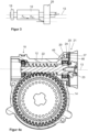
- Figure 1 shows an electromechanical power steering in a schematic, perspective view.
- the electromechanical power steering includes a steering column 1 and a steering gear 2.
- the steering column 1 includes a steering spindle 3, at the end facing the driver a steering wheel 4 is attached.
- the steering wheel 4 can also be referred to as a steering handle.
- the steering gear 2 includes a steering pinion 5, a steering rack 6 and two steering tie rods 7.
- the steering pinion 5 and the steering rack 6 are in engagement with one another.
- the steering gear 2 is used to translate steering commands that can be generated by turning the steering wheel 4 into corresponding rotations of steered vehicle wheels 8.
- the steering pinion 5 is mechanically coupled in a known manner by a kinematic connection to the steering rack 6, the respective steering tie rod 7 and the respective steered vehicle wheel 8.
- the steering command can thus be transmitted from the steering wheel 4 to the respective steered vehicle wheels 8, namely from the steering spindle 3 to the steering gear 2 by mechanical coupling and within the steering gear 2 also by mechanical coupling.
- the steering pinion 5 is driven by the drive module 11 to provide steering support.
- the electromechanical power steering can alternatively be designed as a steer-by-wire steering system, not shown in the figures, so that the steering command is transmitted from the steering wheel 4 to the respective steered vehicle wheels 8, namely from the steering spindle 3 to the steering gear 2 by electrical means Coupling and within the steering gear 2 by mechanical coupling.
- the electrical coupling can be in the form of a data transmission device, for example a data cable.
- a drive module 9 and the drive module 11 are shown in the electromechanical power steering in this exemplary embodiment.
- the drive module 9 and the drive module 11 each include - in Figure 1 not explicitly shown - a drive motor, a housing, a worm gear with a worm shaft and a worm wheel, the worm shaft being mounted in a bearing arrangement.
- a drive module can be attached to the steering column 1 or have an auxiliary power drive 31 coupled to the steering shaft 10 on the steering pinion 5.
- the drive modules 9, 11 can be constructed in the same way. Through the drive module 9, 11, an auxiliary torque can be coupled into the steering spindle 3 and/or the steering pinion 5 in order to support the driver in the steering work.
- the electromechanical power steering only has one drive module 9 or one drive module 11, in particular on one of the in Figure 1 positions shown.
- FIG. 9 An exemplary embodiment of a drive module 9 is described with reference to Figure 2 explained in more detail.
- the bearing arrangement of the drive module 9 can in particular, as with reference to the exemplary embodiments according to Figure 3 to Figure 6e explained, trained.
- the drive module 11 can be constructed accordingly.
- FIG. 2 shows an exemplary embodiment of a drive module 9, 11 for an electromechanical power steering in a schematic, perspective view, comprising a worm gear 10 and a drive motor 11.
- the worm gear 10 includes an in Figure 2 worm shaft 12, not shown, with a worm shaft rotation axis 13 and a worm wheel 14 with a worm wheel rotation axis 15.
- the worm shaft rotation axis 13 is the longitudinal axis of the worm shaft 12.
- the worm shaft 12, also referred to as a worm is protected by a housing element 16 and a housing cover 17 of the worm gear 10 protected from dirt and foreign bodies.
- the worm shaft 12 is supported by an in Figure 2 bearing arrangement, not shown, the bearing arrangement in particular, as with reference to Figure 4a to Figure 6e explained, can be trained.
- the drive motor 11 drives the worm shaft 12, which is rotatably mounted about the worm shaft rotation axis 13.
- the worm shaft 12 is in engagement with the worm wheel 14.
- the worm wheel 14 therefore rotates about the worm wheel rotation axis 15.
- An output shaft 18 is non-rotatably connected to the worm wheel 14 and rotates together with the worm wheel 14 about the worm wheel rotation axis 15.
- Figure 3 shows an exemplary embodiment of a bearing arrangement in a highly simplified diagram.
- the bearing arrangement includes the worm shaft 12, which is rotatably mounted about the worm shaft rotation axis 13.
- the worm shaft 12 is supported at its first, axial end by a first pivot bearing 19 and at its second, axial end by a second pivot bearing 20.
- the first pivot bearing 19 is designed to allow a defined pivoting movement of the worm shaft 12.
- the second pivot bearing 20 is designed as a swivel pivot bearing in that the second pivot bearing 20 is located within an in Figure 3 Swivel ring, not shown, is arranged.
- load case A differs from each other in that the worm shaft 12 rotates in opposite directions.
- a tooth force F A,1 acts at the point of engagement between the worm shaft 12 and the in Figure 3 worm wheel 14, not shown, in the direction of the second pivot bearing 20.
- the tooth force F A,1 causes a bearing reaction force F A,2 . This results in a reaction torque that pushes or pivots the worm shaft 12 in the direction of the worm wheel 14.
- a tooth force F B,1 acts at the point of engagement between the worm shaft 12 and the worm wheel 14 in the direction of the first pivot bearing 19.
- the tooth force F B,1 causes a bearing reaction force F B,2 . This also results in a reaction torque that pushes or pivots the worm shaft 12 in the direction of the worm wheel 14.
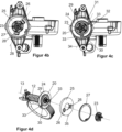
- Figure 4a shows a first embodiment of a bearing arrangement designed according to the invention in a sectional view with a breakout.
- the bearing arrangement is designed as a fixed-loose bearing and comprises a first rotary bearing 19 forming the floating bearing, a second rotary bearing 20 forming the fixed bearing and a pivot ring 21.
- the two rotary bearings 19, 20 are each designed as rolling ball bearings.
- the first pivot bearing 19 is fixed to its outer ring 45 in the direction of the worm shaft rotation axis 13 and is free of fixations on its inner ring in the direction of the worm shaft rotation axis 13, so that the first pivot bearing 19 cannot absorb any forces acting in the direction of the worm shaft rotation axis 13, but rather can only absorb radial forces.
- the first pivot bearing 19 is designed to allow a defined pivoting movement of the worm shaft 12.
- the bearing arrangement serves to support the worm shaft 12, which meshes with the worm wheel 14, in a housing 22 of an electromechanical power steering system.
- the pivot ring 21 is designed to accommodate the second pivot bearing 20 in a form-fitting manner. Specifically, the second pivot bearing 20 is received on its outer ring 45 in the direction of the worm shaft rotation axis 13 by the pivot ring 21, in that a shoulder 46 formed integrally in the outer ring 45 of the second pivot bearing 20 is received in a form-fitting manner by the pivot ring 21.
- the inner ring of the second pivot bearing 20 is fixed in the direction of the worm shaft rotation axis 13 by pressing the inner ring against a shoulder formed in the worm shaft 12 by a securing element 23 that can be screwed onto the end of the worm shaft 12.
- the second pivot bearing 20 can absorb forces and radial forces acting in the direction of the worm shaft rotation axis 13.
- the swivel ring 21 comprises a slotted ring 24 as a first swivel ring component and a sleeve-shaped element 25 as a second swivel ring component, the sleeve-shaped element 25 having a central recess.
- the sleeve-shaped element 25 comprises a disk-shaped section with a central recess and a wall section connected to the disk-shaped section at its radially outer edge and extending in the direction of the worm shaft rotation axis 13.
- the wall section is designed as a raised edge.
- the disk-shaped section and the wall section have approximately the same wall thickness.
- Figure 4b shows the bearing arrangement Figure 4a in a side view.
- tongues 26 are formed as two second points, the tongues 26 each extending in the direction of the worm shaft rotation axis 13.
- the slotted ring 24 and the sleeve-shaped element 25 are arranged directly adjacent or directly adjacent to one another in the direction of the worm shaft rotation axis 13.
- the pivot ring 21 is designed to act resiliently between the second pivot bearing 20 and the housing 22.
- the sleeve-shaped element 25 of the pivot ring 21 is supported on the axial end facing away from the second pivot bearing 20 Worm shaft 12 on a locking ring 27 designed as a snap ring or bore locking ring in the direction of the worm shaft rotation axis 13.
- the locking ring 27 is embedded or fixed in a form-fitting manner in the opening of the housing 22.
- the pivot ring 21 is designed to form a pivot axis.
- the worm shaft 12 can be pivoted by the bearing arrangement about the pivot axis towards the worm wheel 14.
- the position or spatial position or orientation of the pivot axis depends on the direction of rotation of the worm shaft 12, that is, on the load direction, and on the amount of the load moment.
- the direction of rotation dependence of the position of the pivot axis is implemented as follows.
- the second pivot bearing 20 is pressed against the sleeve-shaped element 25 by the geometry of the meshing teeth of the worm shaft 12 and the worm wheel 14, the sleeve-shaped element 25 being one of its geometrical dimensions Design has corresponding spring action, which in turn causes a reaction moment that presses or pivots the worm shaft 12 in the direction of the worm wheel 14.
- This load case corresponds to load case A Figure 3 .
- the load dependence that is to say the dependence on the amount of the load moment, of the sleeve-shaped element 25 is realized by the elasticity or flexibility of the tongues 26.
- the larger the amount of the load moment the stronger the elastic deformation of the tongues 26 and the greater it is restoring spring force caused by the tongues 26.
- the pivoting of the worm shaft 12 serves to reduce the gear play between the worm shaft 12 and the worm wheel 14.
- the pivot axis runs orthogonally to the radial vector of the worm wheel 14.
- the tongues 26 of the sleeve-shaped element 25 are positioned in such a way that the axis 28 connecting the tongues 26, also referred to as the support point axis or as the second axis, deviates from an axis passing through the worm shaft rotation axis 13, that is, runs off-center, that is, not through the The center of the worm wheel 14 runs through, that is, it does not run through the worm shaft rotation axis 13.
- the tongues 26 are oriented opposite to one another in the circumferential direction.
- the swivel ring 21 is designed such that the swivel axis is formed by sprung support points, which correspond in particular to the two first points of the first swivel ring component and the two second points of the second swivel ring component.
- the position of the pivot axis therefore changes depending on the load.
- the spring-loaded support points are formed by the tongues 26 of the sleeve-shaped element 25.
- the tongues 26 form a point-shaped contact contact between the sleeve-shaped element 25 and the second pivot bearing 20.
- the tongues 26 are elastically deformable and thus have a spring effect in the direction of the worm shaft rotation axis 13.
- the point-shaped support contacts move depending on the forces acting in the direction of the worm shaft rotation axis 13, that is to say on the axial forces.
- Each tongue 26 forms a support point.
- the two tongues 26 thus form the support point axis 28, i.e. in particular the second axis formed by the two second points.
- Figure 4c shows the bearing arrangement Figure 4a in another side view. Compared to the side view Figure 4b
- the locking ring 27 and the sleeve-shaped element 25 are not shown, so that the view of the slotted ring 24, i.e. the first swivel ring component, is clear.
- a first circular arc-shaped, radially inner slot 29 and a second, circular arc-shaped, radially outer slot 30 are formed in the slotted ring 24.
- the first slot 29 and the second slot 30 partially overlap in the circumferential direction, so that a first partial circular ring 31 and a second partial circular ring 32 are created.
- the first partial circular ring 31 and the second partial circular ring 32 are connected by two webs 33.
- the webs 33 are in particular the first two points of the first swivel ring component.
- the two webs 33 each form a material taper between the first partial circular ring 31 and the second partial circular ring 32, so that the first partial circular ring 31 and the second partial circular ring 32 can be pivoted about an axis 34 connecting the two webs 33, also referred to as the taper point axis 34 or as the first axis is.
- the maximum possible stroke for the sleeve-shaped element 25 is determined by the distance to the shoulder 46, for the slotted one Ring 24 through the distance between the support in the housing 22 and the second partial circular ring 32 of the ring 24.
- the load dependence of the slotted ring 24 is realized by the elasticity or flexibility of the webs 33 and thus in particular by the first two points of the first swivel ring component.
- the course or the spatial position or the orientation of the pivot axis is dependent on the respective courses or spatial positions or orientations of the support point axis 28 and the taper point axis 34, and thus in particular on the second axis formed by the two second points of the second pivot ring component and the first axis formed by the two first points of the first pivot ring component.
- the pivot axis of the pivot ring 21 runs parallel to the support point axis 28 and the taper point axis 34 and centrally between the support point axis 28 and the taper point axis 34.
- the pivot axis of the pivot ring 21 also runs parallel to the support point axis 28 and the taper point axis 34. However, the pivot axis then does not run centrally between the second axis 28 and the first axis 34, but rather Depending on the direction of rotation of the worm shaft 12 and on the amount of the load torque to be overcome, closer to the support point axis 28 formed by the two tongues 26, i.e. the second axis 28, or closer to the taper point axis 34 formed by the two webs 33, i.e. the first axis 34.
- the pivot axis runs closer to the support point axis 28, that is, further away from the taper point axis 34 when the tooth forces are directed in the direction of the sleeve-shaped element 25. This corresponds to load case A Figure 3 .
- the pivot axis runs closer to the taper point axis 34, that is, further away from the support point axis 28 when the tooth forces are directed in the direction of the slotted ring 24. This corresponds to load case B Figure 3 .
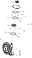
- Figure 4d shows the bearing arrangement Figure 4a in a view pulled apart along the worm shaft rotation axis 13.
- the sleeve-shaped element 25 includes an anti-twist device 35.
- the anti-twist device 35 ensures that the sleeve-shaped element 25 does not twist relative to the other components over time during operation. This ensures that the pivot axis maintains its intended spatial position.
- the anti-rotation device 35 is designed as a formation extending in the radial direction.
- the anti-rotation device 35 is formed in one piece with the sleeve-shaped element 25. Alternatively, the anti-rotation device 35 can also be designed as a separate component that can be connected to the sleeve-shaped element 25.
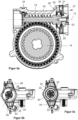
- Figure 5a shows a second embodiment for a bearing arrangement designed according to the invention in a sectional view.
- This second embodiment is fundamentally analogous to the first embodiment Figures 4a-d built up.
- components and components that correspond to the first embodiment are considered to be described accordingly at this point.
- Figure 5b shows the bearing arrangement Figure 5a in a side view.
- the tongues 26, i.e. in particular the two second points, of the sleeve-shaped element 25, i.e. in particular the second swivel ring component, are positioned such that the support point axis 28 connecting the two tongues 26, i.e. in particular the second axis 28 formed by the two second points, is one
- the axis passing through the worm shaft rotation axis 13 is, that is, it runs centrally, that is, it runs through the center of the worm wheel 14, that is, it runs through the worm shaft rotation axis 13.
- Figure 5c shows the bearing arrangement Figure 5a in another side view. Compared to the side view Figure 5b
- the locking ring 27 and the sleeve-shaped element 25 are not shown, so that the view of the slotted ring 24, in particular the first swivel ring component, is clear.
- two webs 33 are formed in the slotted ring 24, i.e. in particular two first points of the first swivel ring component.
- the two webs 33 each form a material taper between the first partial circular ring 31 and the second partial circular ring 32, so that the first Partial circular ring 31 and the second partial circular ring 32 can be pivoted about the taper point axis 34 connecting the webs 33, i.e. in particular about the first axis 34 formed by the two first points.
- the support point axis 28 formed by the two tongues 26, i.e. in particular the second axis 28, runs centrally and that the pivot axis of the swivel ring 21 depends on the support point axis 28, i.e. in particular on the second axis 28, and the taper point axis 34, i.e. in particular the first axis 34, the pivot axis of the pivot ring 21 of the second embodiment runs differently than the pivot axis of the pivot ring 21 of the first embodiment Figures 4a-d .
- Figure 5d shows the bearing arrangement Figure 5a in a view pulled apart along the worm shaft rotation axis 13.
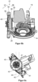
- Figure 6a shows a third embodiment of the bearing arrangement according to the invention in a sectional view with a breakout.
- the worm shaft 13 is not shown.
- the third embodiment of the bearing arrangement according to the invention is fundamentally similar to the first and second embodiments Figures 4a-d or 5a-d constructed. To avoid repetition, components and components that correspond to the first and second embodiments are considered to be described accordingly at this point.
- the swivel ring 21 comprises a first receiving unit 36 with a central recess as the first swivel ring component and a second receiving unit 37 with a central recess as the second swivel ring component.
- the first receiving unit 36 and the second receiving unit 37 each comprise an annular element 38 and a spring unit 39 for the suspension acting in the axial direction, that is to say in the direction of the worm shaft rotation axis 13.
- the spring units 39 each include two separate elastomer cushions. The elastomer cushions in particular form the two first points of the first swivel ring component and the two second points of the second swivel ring component.
- the second pivot bearing 20 is connected to the first receiving unit 36 and the second receiving unit 37 in that the outer ring of the second pivot bearing 20 has a shoulder delimited by an axially central shoulder to the axial stop at both axial ends.
- the two shoulders are designed to accommodate the first receiving unit 36 and the second receiving unit 37.
- the pivot ring 21 further comprises a support element 40 with a central recess, the support element 40 being designed to accommodate the spring unit 39 of the second receiving unit 37.
- Figure 6b shows the bearing arrangement Figure 6a in a sectioned, perspective view with a breakout, the worm shaft 13 not being shown for a better overview.
- Figure 6c shows the bearing arrangement Figure 6a in a side view.
- the annular element 38 of the first receiving unit 36 has formations 41 running in the tangential direction for receiving the associated spring unit 39.
- the formations 41 of the annular element 38 of the first receiving unit 36 form a first formation point axis 42, which corresponds in particular to the first axis 42 formed by the two first points of the first pivot ring component.
- the annular element 38 of the second receiving unit 37 has formations 43 running in the radial direction for receiving the associated spring unit.
- the formations 43 of the annular element 38 of the second receiving unit 37 form a second formation point axis 44, which corresponds in particular to the second axis 44 formed by the two second points of the second pivot ring component.
- the course or the spatial position or the orientation of the pivot axis of the pivot ring 21 is dependent on the respective courses or spatial positions or orientations of the first shaping point axis 42 and the second shaping point axis 44, i.e. in particular on the one through the two first points of the first first axis 42 formed by the swivel ring component and the second axis 44 formed by the two second points of the second swivel ring component.
- the pivot axis runs parallel to and centrally between the first axis 42 and the second axis 44, i.e. in particular the shaping point axes 42, 44.
- the pivot axis of the pivot ring 21 also runs parallel to the first and second shaping point axes 42, 44. However, the pivot axis then does not run centrally between the two axes 42, 44, but depends on the direction of rotation of the worm shaft 12 and the amount of the load torque to be overcome is closer to the second forming point axis 44 formed by the second receiving unit 37 or closer to the first forming point axis 42 formed by the first receiving unit 36. Specifically, the pivot axis runs closer to the second forming point axis 44 , that is, further away from the first molding point axis 42 when the tooth forces are directed in the direction of the second receiving unit 37.
- Figure 6d shows the bearing arrangement Figure 6a in a perspective view without housing.
- Figure 6e shows the bearing arrangement Figure 6a in a view pulled apart along the worm shaft rotation axis 13.
Landscapes
- Engineering & Computer Science (AREA)
- General Engineering & Computer Science (AREA)
- Mechanical Engineering (AREA)
- Chemical & Material Sciences (AREA)
- Combustion & Propulsion (AREA)
- Transportation (AREA)
- Gear Transmission (AREA)
- Power Steering Mechanism (AREA)
Claims (16)
- Agencement de palier pour le montage d'un arbre à vis sans fin (12) engrenant avec une roue à vis sans fin (14) dans un boîtier (22) d'une direction assistée électromécanique, comprenant un premier palier de rotation (19), un deuxième palier de rotation (20) et une bague de pivotement (21), le premier palier de rotation (19) étant conçu de telle sorte, permettre un mouvement de pivotement de l'arbre à vis sans fin (12), la bague de pivotement (21) comprenant un premier composant de bague de pivotement (24, 36) et un deuxième composant de bague de pivotement (25, 37) et étant adaptée pour agir de manière élastique entre le deuxième palier de pivotement (20) et le boîtier (22), et dans lequel le deuxième palier de pivotement (20) est disposé dans la bague de pivotement (21) au moins partiellement entre le premier composant de bague de pivotement (24, 36) et le deuxième composant de bague de pivotement (25, 37), caractérisé en ce que le premier composant de bague de pivotement (24, 36) comporte deux premiers points (33, 39), par rapport auxquels le premier composant annulaire de pivotement (24, 36) est réalisé de manière élastique, et le deuxième composant annulaire de pivotement (25, 37) présente deux deuxièmes points (26, 39), par rapport auxquels le deuxième composant annulaire de pivotement (25, 37) est réalisé de manière élastique.
- Agencement de palier selon la revendication 1, caractérisé en ce que les deux premiers points (33, 39) forment un premier axe (34, 42) et les deux seconds points (26, 39) forment un second axe (28, 44), le premier axe (34, 42) et le second axe (28, 44) n'étant pas superposables.
- Agencement de bord de palier selon la revendication 1 ou la revendication 2, caractérisé en ce que les deux premiers points (33, 39) et les deux deuxièmes points (26, 39) sont respectivement des points d'appui à ressort.
- Agencement de palier selon l'une des revendications 1 à 3, caractérisé en ce que la bague de pivotement (21) est configurée de manière à former un axe de pivotement, notamment de manière à ce que l'axe de pivotement soit orthogonal au vecteur radial de la roue hélicoïdale (14).
- Agencement de palier selon l'une des revendications 1 à 4, caractérisé en ce que la bague pivotante (21) est configurée de telle sorte que l'axe de pivotement est formé par les deux premiers points (33, 39) et les deux seconds points (26, 39).
- Agencement de palier selon l'une des revendications 1 à 5, caractérisé en ce que la bague pivotante (21) modifie la position de l'axe de pivotement en fonction du sens de rotation de l'arbre à vis sans fin (12) par l'intermédiaire des deux premiers points (33, 39) et des deux deuxièmes points (26, 39).
- Agencement de palier selon l'une des revendications 1 à 6, caractérisé en ce que la bague pivotante (21) modifie la position de l'axe de pivotement en fonction de la valeur du couple de charge à surmonter par l'intermédiaire des deux premiers points (33, 39) et des deux deuxièmes points (26, 39).
- Agencement de palier selon l'une des revendications 1 à 7, caractérisé en ce que le deuxième palier rotatif (20) présente une bague extérieure (45), la bague extérieure (45) formant un épaulement (46) ou un talon sur lequel est disposé le premier composant annulaire de pivotement (24, 36) et/ou le deuxième composant annulaire de pivotement (25, 37), l'épaulement (46) ou le talon servant notamment de butée mécanique pour le premier composant annulaire de pivotement (24, 36) et/ou le deuxième composant annulaire de pivotement (25, 37).
- Agencement de palier selon l'une des revendications 1 à 8, caractérisé en ce que le deuxième palier rotatif (20) comporte une bague extérieure (45), la bague extérieure (45) formant un épaulement (46), l'épaulement (46) étant reçu par complémentarité de forme par la bague pivotante (21).
- Agencement de palier selon l'une quelconque des revendications 1 à 9, caractérisé en ce que la bague pivotante (21) comprend une bague fendue (24) en tant que premier composant de bague pivotante et un élément en forme de manchon (25) en tant que second composant de bague pivotante.
- Agencement de palier selon la revendication 10, caractérisé en ce qu' une première fente (29) radialement intérieure, en forme d'arc de cercle, et une deuxième fente (30) radialement extérieure, en forme d'arc de cercle, sont formées dans la bague fendue (24), la première fente (29) et la deuxième fente (30) se superposant partiellement dans la direction circonférentielle, de sorte qu'il se forme un premier anneau circulaire partiel (31) et un deuxième anneau circulaire partiel (32), le premier anneau circulaire partiel (31) et le deuxième anneau circulaire partiel (32) étant reliés par deux entretoises (33) constituant les deux premiers points.
- Agencement de palier selon la revendication 10 ou la revendication 11, caractérisé en ce que l'élément en forme de manchon (25) comprend une partie en forme de disque avec un évidement central et une partie de paroi reliée à la partie en forme de disque au niveau de son bord radialement extérieur et s'étendant dans la direction axiale de l'arbre à vis sans fin (12), des languettes (26) étant formées dans la partie en forme de disque en tant que les deux seconds points, les languettes (26) s'étendant chacune dans la direction axiale de l'arbre à vis sans fin (12), les languettes (26) étant positionnées en particulier de telle sorte que l'axe (28) reliant les languettes (26) soit un axe passant par l'axe longitudinal de l'arbre à vis sans fin (12).
- Agencement de palier selon l'une quelconque des revendications 1 à 9, caractérisé en ce que la bague pivotante (21) comprend une première unité de réception (36) à évidement central constituant le premier composant de la bague pivotante et une deuxième unité de réception (37) à évidement central constituant le deuxième composant de la bague pivotante, la première unité de réception (36) et la deuxième unité de réception (37) comprenant chacune un élément annulaire (38) et une unité de ressort (39) pour la suspension agissant dans la direction axiale, l'unité de ressort (39) formant respectivement les deux premiers points et les deux deuxièmes points, et en ce que la bague pivotante (21) comprend en particulier un élément de support (40) avec un évidement central, l'élément de support (40) étant conçu de manière à recevoir l'unité de ressort (39) d'une des unités de réception (36, 37).
- Agencement de palier selon une revendication 13, caractérisé en ce que l'élément annulaire (38) de la première unité de réception (36) présente des formations (41) s'étendant dans la direction tangentielle pour recevoir l'unité de ressort (39) correspondante.
- Agencement de palier selon la revendication 13 ou la revendication 14, caractérisé en ce que l'élément annulaire (38) de la deuxième unité de réception (37) présente des conformations (43) s'étendant dans la direction radiale pour recevoir l'unité de ressort (39) correspondante.
- Direction assistée électromécanique avec un module de propulsion comprenant un moteur de propulsion (11), un boîtier (22), un engrenage à vis sans fin (10) et un agencement de paliers, dans laquelle l'engrenage à vis sans fin (10) comprend un arbre à vis sans fin (12) avec un axe de rotation d'arbre à vis sans fin (13) et une roue à vis sans fin (14) avec un axe de rotation de roue à vis sans fin (15), et dans laquelle l'arbre à vis sans fin (12) est logé dans l'agencement de paliers, caractérisée en ce que l'agencement de paliers est réalisé selon l'une des revendications 1 à 15.
Applications Claiming Priority (2)
| Application Number | Priority Date | Filing Date | Title |
|---|---|---|---|
| DE102020201761.1A DE102020201761A1 (de) | 2020-02-12 | 2020-02-12 | Lageranordnung |
| PCT/EP2021/053117 WO2021160626A1 (fr) | 2020-02-12 | 2021-02-10 | Ensemble palier |
Publications (2)
| Publication Number | Publication Date |
|---|---|
| EP3914502A1 EP3914502A1 (fr) | 2021-12-01 |
| EP3914502B1 true EP3914502B1 (fr) | 2023-10-11 |
Family
ID=74595273
Family Applications (1)
| Application Number | Title | Priority Date | Filing Date |
|---|---|---|---|
| EP21705134.1A Active EP3914502B1 (fr) | 2020-02-12 | 2021-02-10 | Ensemble palier |
Country Status (5)
| Country | Link |
|---|---|
| US (1) | US20220371652A1 (fr) |
| EP (1) | EP3914502B1 (fr) |
| CN (1) | CN115103965B (fr) |
| DE (1) | DE102020201761A1 (fr) |
| WO (1) | WO2021160626A1 (fr) |
Families Citing this family (1)
| Publication number | Priority date | Publication date | Assignee | Title |
|---|---|---|---|---|
| CN115949670B (zh) * | 2023-03-09 | 2023-06-30 | 中国航发四川燃气涡轮研究院 | 用于轴承轴向压紧的弹性结构 |
Family Cites Families (19)
| Publication number | Priority date | Publication date | Assignee | Title |
|---|---|---|---|---|
| DE8418450U1 (de) | 1984-11-29 | Fritz Himmermann GmbH & Co KG, 5374 Hellenthal | Kunststoffgleitlager | |
| ZA802145B (en) * | 1979-05-29 | 1981-04-29 | Eaton Corp | Improved slack adjuster |
| DE102008001878A1 (de) * | 2008-05-20 | 2009-11-26 | Zf Lenksysteme Gmbh | Schraubradgetriebe mit schwenkbar gelagertem Schraubritzel und damit ausgestattete elektrische Hilfskraftlenkung |
| DE102008040673B4 (de) | 2008-06-24 | 2018-07-26 | Robert Bosch Automotive Steering Gmbh | Wellenlagerung in einem Lenksystem und damit ausgestattetes Lenkgetriebe und Herstellungsverfahren dafür |
| DE102009054655A1 (de) | 2009-12-15 | 2011-06-16 | Zf Lenksysteme Gmbh | Lenkgetriebe mit Festlager und Loslager für Schraubritzel |
| DE102012103147A1 (de) | 2012-04-12 | 2013-10-17 | Zf Lenksysteme Gmbh | Loslager für ein lenkgetriebe |
| DE102013007883A1 (de) | 2013-05-08 | 2014-11-13 | Thyssenkrupp Presta Ag | Anfederungs-Exzenterschwinge in CEPS-Anwendung |
| GB201504958D0 (en) * | 2015-03-24 | 2015-05-06 | Trw Ltd | A gearbox assembly for an electric power steering assembly |
| DE102016104150A1 (de) * | 2016-03-08 | 2017-09-14 | Robert Bosch Automotive Steering Gmbh | Lenkgetriebe |
| DE102016006156A1 (de) * | 2016-05-23 | 2017-11-23 | Thyssenkrupp Ag | Elektromechanische Servolenkung mit schwenkbarem Lager für ein Schraubradgetriebe |
| DE202016103794U1 (de) * | 2016-06-29 | 2016-07-29 | Ford Global Technologies, Llc | Getriebeeinheit für ein Kraftfahrzeug |
| DE102016211714B3 (de) * | 2016-06-29 | 2017-09-07 | Ford Global Technologies, Llc | Getriebeeinheit für ein Kraftfahrzeug |
| DE102016211694B3 (de) * | 2016-06-29 | 2017-10-05 | Ford Global Technologies, Llc | Getriebeeinheit für ein Kraftfahrzeug |
| DE102016012246A1 (de) * | 2016-10-14 | 2018-04-19 | Thyssenkrupp Ag | Elektromechanische Servolenkung mit gefederter Lageranordnung |
| DE102016122378A1 (de) * | 2016-11-21 | 2018-05-24 | Robert Bosch Gmbh | Lenksystem |
| DE102017207708A1 (de) | 2017-05-08 | 2018-11-08 | Robert Bosch Gmbh | Festlager, Lenkgetriebe und Lenksystem |
| GB201710388D0 (en) | 2017-06-29 | 2017-08-16 | Trw Ltd | Gearbox assembly |
| CN110143172A (zh) * | 2018-02-11 | 2019-08-20 | 比亚迪股份有限公司 | 用于调节显示终端的执行机构和车辆 |
| DE102018106025A1 (de) * | 2018-03-15 | 2019-09-19 | Thyssenkrupp Ag | Schraubradgetriebe für eine elektromechanische Servolenkung mit einem asymmetrisch vorgespannten Festlager |
-
2020
- 2020-02-12 DE DE102020201761.1A patent/DE102020201761A1/de active Pending
-
2021
- 2021-02-10 WO PCT/EP2021/053117 patent/WO2021160626A1/fr unknown
- 2021-02-10 EP EP21705134.1A patent/EP3914502B1/fr active Active
- 2021-02-10 CN CN202180002469.7A patent/CN115103965B/zh active Active
- 2021-02-10 US US17/439,717 patent/US20220371652A1/en active Pending
Also Published As
| Publication number | Publication date |
|---|---|
| CN115103965B (zh) | 2024-02-20 |
| WO2021160626A1 (fr) | 2021-08-19 |
| DE102020201761A1 (de) | 2021-08-12 |
| US20220371652A1 (en) | 2022-11-24 |
| CN115103965A (zh) | 2022-09-23 |
| EP3914502A1 (fr) | 2021-12-01 |
Similar Documents
| Publication | Publication Date | Title |
|---|---|---|
| EP2964509B1 (fr) | Système de palier à mobilité angulaire pour pignons d'engrenages réducteurs de systèmes de direction électromécaniques | |
| EP2994362B1 (fr) | Bielle oscillante à excentrique de suspension à ressort dans une utilisation ceps | |
| WO2002077487A2 (fr) | Transmission a vis et a corps de roulement et systeme d'entrainement d'un module bielle de liaison d'essieu d'un vehicule automobile | |
| DE102008001878A1 (de) | Schraubradgetriebe mit schwenkbar gelagertem Schraubritzel und damit ausgestattete elektrische Hilfskraftlenkung | |
| WO2013056770A1 (fr) | Direction électromécanique de véhicule à moteur | |
| EP3526103A1 (fr) | Direction assistée électromécanique comprenant un agencement de palier à ressort | |
| DE102017209563A1 (de) | Loslager, Lenkgetriebe und Lenksystem | |
| EP3544878A1 (fr) | Mécanisme de direction et système de direction | |
| EP3864311A1 (fr) | Palier lisse pour une barre d'accouplement d'un système de direction à commande électrique | |
| DE112016002670T5 (de) | Getriebeanordnung für elektrische Servolenkung | |
| DE69819826T2 (de) | Servosteuersystem | |
| EP3426541B1 (fr) | Mécanisme de direction | |
| EP3914502B1 (fr) | Ensemble palier | |
| WO2013083538A1 (fr) | Vis à billes | |
| EP1334295B1 (fr) | Differentiel destine a l'entrainement d'axe d'un vehicule | |
| DE102018217459A1 (de) | Lenkgetriebe und Lenksystem für ein Kraftfahrzeug | |
| DE102018130734A1 (de) | Kugelmutterbaugruppe für eine servolenkungbaugruppeeines fahrzeugs | |
| DE102017211461A1 (de) | Lenkgetriebe | |
| DE102020214844A1 (de) | Lenksystem für ein Kraftfahrzeug | |
| DE10254129B4 (de) | Elektromotorischer Möbelantrieb zum Verstellen von Teilen eines Möbels relativ zueinander | |
| EP3691957B1 (fr) | Direction assistée électromécanique munie d'un engrenage à roue hélicoïdale et d'un dispositif de compensation servant d'appui à un palier libre au niveau du carter d'engrenage | |
| WO2014056571A1 (fr) | Direction à crémaillère | |
| EP3765758B1 (fr) | Engrenage à vis sans fin comprenant un palier pivotant comprenant un axe de pivotement défini | |
| WO2016173840A1 (fr) | Boîtier de direction muni d'un pignon monté élastiquement | |
| DE102019219125A1 (de) | Lagervorrichtung für ein Festlager und Lenkgetriebe |
Legal Events
| Date | Code | Title | Description |
|---|---|---|---|
| STAA | Information on the status of an ep patent application or granted ep patent |
Free format text: STATUS: UNKNOWN |
|
| STAA | Information on the status of an ep patent application or granted ep patent |
Free format text: STATUS: THE INTERNATIONAL PUBLICATION HAS BEEN MADE |
|
| PUAI | Public reference made under article 153(3) epc to a published international application that has entered the european phase |
Free format text: ORIGINAL CODE: 0009012 |
|
| STAA | Information on the status of an ep patent application or granted ep patent |
Free format text: STATUS: REQUEST FOR EXAMINATION WAS MADE |
|
| 17P | Request for examination filed |
Effective date: 20210823 |
|
| AK | Designated contracting states |
Kind code of ref document: A1 Designated state(s): AL AT BE BG CH CY CZ DE DK EE ES FI FR GB GR HR HU IE IS IT LI LT LU LV MC MK MT NL NO PL PT RO RS SE SI SK SM TR |
|
| RAP3 | Party data changed (applicant data changed or rights of an application transferred) |
Owner name: THYSSENKRUPP AG Owner name: THYSSENKRUPP PRESTA AG |
|
| DAV | Request for validation of the european patent (deleted) | ||
| DAX | Request for extension of the european patent (deleted) | ||
| GRAP | Despatch of communication of intention to grant a patent |
Free format text: ORIGINAL CODE: EPIDOSNIGR1 |
|
| STAA | Information on the status of an ep patent application or granted ep patent |
Free format text: STATUS: GRANT OF PATENT IS INTENDED |
|
| INTG | Intention to grant announced |
Effective date: 20230719 |
|
| GRAS | Grant fee paid |
Free format text: ORIGINAL CODE: EPIDOSNIGR3 |
|
| GRAA | (expected) grant |
Free format text: ORIGINAL CODE: 0009210 |
|
| STAA | Information on the status of an ep patent application or granted ep patent |
Free format text: STATUS: THE PATENT HAS BEEN GRANTED |
|
| AK | Designated contracting states |
Kind code of ref document: B1 Designated state(s): AL AT BE BG CH CY CZ DE DK EE ES FI FR GB GR HR HU IE IS IT LI LT LU LV MC MK MT NL NO PL PT RO RS SE SI SK SM TR |
|
| REG | Reference to a national code |
Ref country code: GB Ref legal event code: FG4D Free format text: NOT ENGLISH |
|
| REG | Reference to a national code |
Ref country code: CH Ref legal event code: EP |
|
| REG | Reference to a national code |
Ref country code: DE Ref legal event code: R096 Ref document number: 502021001700 Country of ref document: DE |
|
| REG | Reference to a national code |
Ref country code: IE Ref legal event code: FG4D Free format text: LANGUAGE OF EP DOCUMENT: GERMAN |
|
| REG | Reference to a national code |
Ref country code: DE Ref legal event code: R084 Ref document number: 502021001700 Country of ref document: DE |
|
| REG | Reference to a national code |
Ref country code: LT Ref legal event code: MG9D |
|
| REG | Reference to a national code |
Ref country code: NL Ref legal event code: MP Effective date: 20231011 |
|
| PG25 | Lapsed in a contracting state [announced via postgrant information from national office to epo] |
Ref country code: NL Free format text: LAPSE BECAUSE OF FAILURE TO SUBMIT A TRANSLATION OF THE DESCRIPTION OR TO PAY THE FEE WITHIN THE PRESCRIBED TIME-LIMIT Effective date: 20231011 |
|
| PG25 | Lapsed in a contracting state [announced via postgrant information from national office to epo] |
Ref country code: GR Free format text: LAPSE BECAUSE OF FAILURE TO SUBMIT A TRANSLATION OF THE DESCRIPTION OR TO PAY THE FEE WITHIN THE PRESCRIBED TIME-LIMIT Effective date: 20240112 |
|
| PG25 | Lapsed in a contracting state [announced via postgrant information from national office to epo] |
Ref country code: IS Free format text: LAPSE BECAUSE OF FAILURE TO SUBMIT A TRANSLATION OF THE DESCRIPTION OR TO PAY THE FEE WITHIN THE PRESCRIBED TIME-LIMIT Effective date: 20240211 |
|
| PG25 | Lapsed in a contracting state [announced via postgrant information from national office to epo] |
Ref country code: LT Free format text: LAPSE BECAUSE OF FAILURE TO SUBMIT A TRANSLATION OF THE DESCRIPTION OR TO PAY THE FEE WITHIN THE PRESCRIBED TIME-LIMIT Effective date: 20231011 |
|
| PG25 | Lapsed in a contracting state [announced via postgrant information from national office to epo] |
Ref country code: ES Free format text: LAPSE BECAUSE OF FAILURE TO SUBMIT A TRANSLATION OF THE DESCRIPTION OR TO PAY THE FEE WITHIN THE PRESCRIBED TIME-LIMIT Effective date: 20231011 |
|
| PG25 | Lapsed in a contracting state [announced via postgrant information from national office to epo] |
Ref country code: LT Free format text: LAPSE BECAUSE OF FAILURE TO SUBMIT A TRANSLATION OF THE DESCRIPTION OR TO PAY THE FEE WITHIN THE PRESCRIBED TIME-LIMIT Effective date: 20231011 Ref country code: IS Free format text: LAPSE BECAUSE OF FAILURE TO SUBMIT A TRANSLATION OF THE DESCRIPTION OR TO PAY THE FEE WITHIN THE PRESCRIBED TIME-LIMIT Effective date: 20240211 Ref country code: GR Free format text: LAPSE BECAUSE OF FAILURE TO SUBMIT A TRANSLATION OF THE DESCRIPTION OR TO PAY THE FEE WITHIN THE PRESCRIBED TIME-LIMIT Effective date: 20240112 Ref country code: ES Free format text: LAPSE BECAUSE OF FAILURE TO SUBMIT A TRANSLATION OF THE DESCRIPTION OR TO PAY THE FEE WITHIN THE PRESCRIBED TIME-LIMIT Effective date: 20231011 Ref country code: BG Free format text: LAPSE BECAUSE OF FAILURE TO SUBMIT A TRANSLATION OF THE DESCRIPTION OR TO PAY THE FEE WITHIN THE PRESCRIBED TIME-LIMIT Effective date: 20240111 Ref country code: PT Free format text: LAPSE BECAUSE OF FAILURE TO SUBMIT A TRANSLATION OF THE DESCRIPTION OR TO PAY THE FEE WITHIN THE PRESCRIBED TIME-LIMIT Effective date: 20240212 |
|
| PGFP | Annual fee paid to national office [announced via postgrant information from national office to epo] |
Ref country code: DE Payment date: 20240219 Year of fee payment: 4 |