EP3914057A1 - Slide rail assembly - Google Patents
Slide rail assembly Download PDFInfo
- Publication number
- EP3914057A1 EP3914057A1 EP20206662.7A EP20206662A EP3914057A1 EP 3914057 A1 EP3914057 A1 EP 3914057A1 EP 20206662 A EP20206662 A EP 20206662A EP 3914057 A1 EP3914057 A1 EP 3914057A1
- Authority
- EP
- European Patent Office
- Prior art keywords
- rail
- wall
- function
- passage
- function member
- Prior art date
- Legal status (The legal status is an assumption and is not a legal conclusion. Google has not performed a legal analysis and makes no representation as to the accuracy of the status listed.)
- Granted
Links
Images





Classifications
-
- H—ELECTRICITY
- H05—ELECTRIC TECHNIQUES NOT OTHERWISE PROVIDED FOR
- H05K—PRINTED CIRCUITS; CASINGS OR CONSTRUCTIONAL DETAILS OF ELECTRIC APPARATUS; MANUFACTURE OF ASSEMBLAGES OF ELECTRICAL COMPONENTS
- H05K7/00—Constructional details common to different types of electric apparatus
- H05K7/14—Mounting supporting structure in casing or on frame or rack
- H05K7/1485—Servers; Data center rooms, e.g. 19-inch computer racks
- H05K7/1488—Cabinets therefor, e.g. chassis or racks or mechanical interfaces between blades and support structures
- H05K7/1489—Cabinets therefor, e.g. chassis or racks or mechanical interfaces between blades and support structures characterized by the mounting of blades therein, e.g. brackets, rails, trays
-
- A—HUMAN NECESSITIES
- A47—FURNITURE; DOMESTIC ARTICLES OR APPLIANCES; COFFEE MILLS; SPICE MILLS; SUCTION CLEANERS IN GENERAL
- A47B—TABLES; DESKS; OFFICE FURNITURE; CABINETS; DRAWERS; GENERAL DETAILS OF FURNITURE
- A47B88/00—Drawers for tables, cabinets or like furniture; Guides for drawers
- A47B88/40—Sliding drawers; Slides or guides therefor
- A47B88/49—Sliding drawers; Slides or guides therefor with double extensible guides or parts
- A47B88/493—Sliding drawers; Slides or guides therefor with double extensible guides or parts with rollers, ball bearings, wheels, or the like
-
- A—HUMAN NECESSITIES
- A47—FURNITURE; DOMESTIC ARTICLES OR APPLIANCES; COFFEE MILLS; SPICE MILLS; SUCTION CLEANERS IN GENERAL
- A47B—TABLES; DESKS; OFFICE FURNITURE; CABINETS; DRAWERS; GENERAL DETAILS OF FURNITURE
- A47B88/00—Drawers for tables, cabinets or like furniture; Guides for drawers
- A47B88/40—Sliding drawers; Slides or guides therefor
- A47B88/423—Fastening devices for slides or guides
-
- F—MECHANICAL ENGINEERING; LIGHTING; HEATING; WEAPONS; BLASTING
- F16—ENGINEERING ELEMENTS AND UNITS; GENERAL MEASURES FOR PRODUCING AND MAINTAINING EFFECTIVE FUNCTIONING OF MACHINES OR INSTALLATIONS; THERMAL INSULATION IN GENERAL
- F16C—SHAFTS; FLEXIBLE SHAFTS; ELEMENTS OR CRANKSHAFT MECHANISMS; ROTARY BODIES OTHER THAN GEARING ELEMENTS; BEARINGS
- F16C29/00—Bearings for parts moving only linearly
- F16C29/04—Ball or roller bearings
- F16C29/045—Ball or roller bearings having rolling elements journaled in one of the moving parts
- F16C29/046—Ball or roller bearings having rolling elements journaled in one of the moving parts with balls journaled in pockets
-
- A—HUMAN NECESSITIES
- A47—FURNITURE; DOMESTIC ARTICLES OR APPLIANCES; COFFEE MILLS; SPICE MILLS; SUCTION CLEANERS IN GENERAL
- A47B—TABLES; DESKS; OFFICE FURNITURE; CABINETS; DRAWERS; GENERAL DETAILS OF FURNITURE
- A47B2210/00—General construction of drawers, guides and guide devices
- A47B2210/0002—Guide construction for drawers
- A47B2210/0029—Guide bearing means
- A47B2210/0032—Balls
Definitions
- the present invention is related to a slide rail assembly with improved slide rail support structure configuration.
- the slide rail assembly includes a first rail 100, a second rail 102, a third rail 104, a first rolling ball device 106, a second rolling ball device 108, a first blocking base 110, a second blocking base 112, a first bracket 114 and a second bracket 116.
- first rolling ball device 106 is arranged between the first rail 100 and the second rail 102.
- second rolling ball device 108 is arranged between the second rail 102 and the third rail 104.
- the first blocking base 110 is fixedly arranged adjacent to a front end of the first rail 100 and configured to block the first rolling ball device 106 from sliding out from the first rail 100 and further support the second rail 102.
- the second blocking base 112 is fixedly arranged adjacent to a front end of the second rail 102 and configured to block the second rolling ball device 108 from sliding out from the second rail 102 and further support the third rail 104.
- the first bracket 114 and the second bracket 116 are respectively arranged on two ends of the first rail 100, in order to mount the slide rail assembly on two posts of a rack. For example, as shown in FIG. 3 , the first bracket 114 is mounted on a front post 118 of a rack.
- Two support members 120 are respectively arranged on an upper side and a lower side of the first bracket 114 (as shown in FIG. 1 and FIG. 3 ), and configured to contact the second rail 102 when the second rail 102 is moved in a passage 122 defined by the upper side and the lower side of the first bracket 114.
- the two support members 120 are able to support the second rail 102, to further improve the supporting ability between the first bracket 114 and the second rail 102.
- FIG. 1 to FIG. 3 is applicant's previous design of the present application (Publication No. EP 2,777,431 B1 ).
- the two support members 120 of a prior art not only needs to be additionally configured, but also needs to ensure the contacting structure which the two support members 120 supporting the slide rail (e.g. the second rail 102) in an extended position, so as to achieve effective support.
- the two support members 120 are arranged on the first bracket 114, a gap 124 is formed between the two support members 120 and the first blocking base 110. Therefore, the structural strength still can be improved.
- the bracket due to the two support members 120 are arranged on the first bracket 114, in order to correspond to the slide rails according to the specifications of different chassis (such as 1U chassis or 2U chassis), the bracket needs to be prepared with components of 1U, 2U or other standards. Extra materials cause extra costs and increase the burden of inventory management.
- the present invention aims at providing a slide rail assembly having improved slide rail support structure configuration.
- the claimed slide rail assembly includes a first rail, a second rail, a sliding auxiliary device and a first function member.
- the first rail includes a first wall, a second wall and a first longitudinal wall connected between the first wall and the second wall. A passage is defined by the first wall, the second wall and the first longitudinal wall.
- the second rail is movably mounted in the passage of the first rail.
- the sliding auxiliary device is arranged in the passage of the first rail.
- the sliding auxiliary device includes a plurality of rolling members configured to support between the first rail and the second rail.
- the first function member is arranged on the first rail and adjacent to an end portion of the first rail. Wherein, the first function member includes a first function portion and a second function portion.
- the first function portion is located in the passage of the first rail.
- the second function portion exceeds the end portion of the first rail and located at outside of the passage of the first rail.
- the second function portion of the first function member is configured to support at least one part of the rail section of the second rail.
- the first function portion of the first function member is configured to prevent the sliding auxiliary device from being moved from the passage of the first rail to the outside of the passage of the first rail.
- a slide rail assembly 20 of an embodiment of the present invention includes a first rail 22, a second rail 24, a sliding auxiliary device 26 and at least one function member (such as a first function member 28 and a second function member 30) .
- the slide rail assembly 20 further includes a third rail 32 and a bracket device 33.
- the first rail 22 has a first end portion 22a and a second end portion 22b (such as a front end portion and a rear end portion, but the present invention is not limited).
- the first rail 22 includes a first wall 34a, a second wall 34b and a first longitudinal wall 36 connected between the first wall 34a and the second wall 34b.
- a passage 38 is defined by the first wall 34a, the second wall 34b and the first longitudinal wall 36.
- the second rail 24 is movably mounted in the passage 38 of the first rail 22.
- the second rail 24 includes a third wall 40a, a fourth wall 40b and a second longitudinal wall 42 connected between the third wall 40a and the fourth wall 40b.
- a passage is defined by the third wall 40a, the fourth wall 40b and the second longitudinal wall 42.
- the third rail 32 is movably mounted in the passage of the second rail 24.
- the sliding auxiliary device 26 is arranged in the passage 38 of the first rail 22.
- the sliding auxiliary device 26 includes a plurality of rolling members 44 configured to improve the smoothness of the movement between the second rail 24 and the first rail 22.
- the sliding auxiliary device 26 includes a first sliding auxiliary portion 26a and a second sliding auxiliary portion 26b.
- the first sliding auxiliary portion 26a and the second sliding auxiliary portion 26b respectively include a plurality of lower rolling balls 44 and a plurality of upper rolling balls 44 (please refer to FIG. 7 and FIG. 8 ).
- the first function member 28 and the second function member 30 are fixedly arranged on the first rail 22 and located adjacent to an end portion of the first rail 22 (e.g. the first end portion 22a).
- the first function member 28 and the second function member 30 both include metal material.
- the first function member 28 is arranged adjacent to the first wall 34a of the first rail 22, and the second function member 30 is arranged adjacent to the second wall 34b of the first rail 22.
- the first function member 28 and the second function member 30 are connected to the first rail 22 by substantially a same connecting method.
- the first function member 28 and the second function member 30 have substantially a same structural configuration.
- the first function member 28 and the first rail 22 respectively have a first connecting portion 46 and a second connecting portion 48 corresponding to the first connecting portion 46.
- the first connecting portion 46 and the second connecting portion 48 are configured to be connected to each other.
- the first connecting portion 46 and the second connecting portion 48 are connected by engaging or fastening.
- the first connecting portion 46 and the second connecting portion 48 may be connected by riveting or welding, but the present invention is not limited thereto.
- the first function member 28 includes a first function portion 50 and a second function portion 52.
- the first function portion 50 and the second function portion 52 are connected by integrated together.
- the first connecting portion 46 is arranged on the first function portion 50, but the present invention is not limited thereto specifically.
- the first function portion 50 is located in the passage 38 of the first rail 22.
- the second function portion 52 exceeds the first end portion 22a of the first rail 22 and located at outside of the passage 38 of the first rail 22.
- the bracket device 33 is connected to the first rail 22 and located adjacent to the first end portion 22a of the first rail 22.
- the bracket device 33 includes a first supporting wall 54a, a second supporting wall 54b and a side wall 56 connected between the first supporting wall 54a and the second supporting wall 54b.
- the first supporting wall 54a is configured to support the first wall 34a of the first rail 22 and the second function portion 52 of the first function member 28.
- the second supporting wall 54b is configured to support the second wall 34b of the first rail 22 and the second function portion 52 of the second function member 30.
- the first supporting wall 54a of the bracket device 33 and the second function portion 52 of the first function member 28 respectively have a first feature 58 and a second feature 60 corresponding to the first feature 58.
- the second supporting wall 54b of the bracket device 33 and the second function portion 52 of the second function member 30 respectively have a third feature 62 and a fourth feature 64 corresponding to the third feature 62.
- the structure of the first feature 58 and the second feature 60 is a combination of concave and convex structures engaged with each other, such that the first supporting wall 54a and the second function portion 52 of the first function member 28 are able to be supported by or engaged with each other.
- the structure of the third feature 62 and the fourth feature 64 is also a combination of concave and convex structures engaged with each other, such that the second supporting wall 54b and the second function portion 52 of the second function member 30 are able to be supported by or engaged with each other.
- the bracket device 33 further includes an end wall 66 substantially bent perpendicularly relative to the side wall 56. At least one mounting member 68 is arranged on the end wall 66. The at least one mounting member 68 is configured to mount the first rail 22 on a rack.
- the slide rail assembly 20 is in a retracted state.
- the second rail 24 is located at a first predetermined position P1 (such as a retracted position, but not limited thereto) relative to the first rail 22, and the third rail 32 is retracted relative to the second rail 24, and the sliding auxiliary device 26 (such as the first sliding auxiliary portion 26a and the second sliding auxiliary portion 26b) is located at a first sliding auxiliary position K1.
- the plurality of lower rolling balls 44 of the first sliding auxiliary portion 26a of the sliding auxiliary device 26 is configured to support between the first wall 34a of the first rail 22 and the third wall 40a of the second rail 24.
- the plurality of upper rolling balls 44 of the second sliding auxiliary portion 26b of the sliding auxiliary device 26 is configured to support between the second wall 34b of the first rail 22 and the fourth wall 40b of the second rail 24.
- the first rail 22 further includes at least one blocking portion 70 adjacent to the second end portion 22b of the first rail 22.
- the at least one blocking portion 70 is configured to prevent the second rail 24 from being moved along a second direction (e.g. a retracing direction) and detached from the first rail 22.
- the second rail 24 further includes at least one pushing portion.
- the second rail 24 includes a first pushing portion 72a and a second pushing portion 72b corresponding to the first sliding auxiliary portion 26a of the sliding auxiliary device 26 and the second sliding auxiliary portion 26b.
- the second function portion 52 of the at least one function member (such as the first function member 28) is able to be configured to support at least one part of the rail section X of the second rail 24.
- the first function portion 50 of the at least one function member (such as the first function member 28) is configured to prevent the sliding auxiliary device 26 from being moved from inside of the passage 38 of the first rail 22 to the outside of the passage 38 of the first rail 22.
- the sliding auxiliary device 26 is pushed by the at least one pushing portion (i.e., the first pushing portion 72a and the second pushing portion 72b) to be moved from the first sliding auxiliary position K1 along the first direction D1 to a second sliding auxiliary position K2 (as shown in FIG.
- the first function portion 50 of the at least one function member (such as the first function member 28 and the second function member 30) is able to block the sliding auxiliary device 26(for example, to block the first sliding auxiliary portion 26a and the second sliding auxiliary portion 26b) to stop at the second sliding auxiliary position K2, in order to prevent the sliding auxiliary device 26 from being moved from the inside the passage 38 of the first rail 22 to the outside of the passage 38 of the first rail 22.
- the second function portion 52 of the first function member 28 and the second function portion 52 of the second function member 30 are respectively configured to support the third wall 40a of the rail section X of the second rail 24 and at least one part of the fourth wall 40b (as shown in FIG. 8 ).
- the second rail 24 when the second rail 24 is moved from the first predetermined position P1 along the first direction D1 to the second predetermined position P2, two ends (such as a front end and a rear end) of the first sliding auxiliary portion 26a respectively abut against the first function portion 50 of the first function member 28 and the first pushing portion 72a of the second rail 24, two ends (such as a front end and a rear end) of the second sliding auxiliary portion 26b respectively abut against the first function portion 50 of the second function member 30 and the second pushing portion 72b of the second rail 24 (as shown in FIG. 8 ).
- the at least one mounting member 68 of the bracket device 33 is configured to mount the first rail 22 to a post 74 of a rack.
- the slide rail assembly 20 is in the extending state.
- the structure configuration of the slide rail assembly 20 in the extending state is shown in FIG. 8 . For simplification, no further illustration is provided.
- a cross-section of the first function member 28 and a cross-section of the second function member 30 both include a first supporting section 76 and a second supporting section 78.
- the first supporting section 76 and the second supporting section 78 of the first function member 28 are respectively configured to correspond to a first ball groove 80a of the first wall 34a of the first rail 22 and a second ball groove 80b of the third wall 40a of the second rail 24 (for example, the supporting section and the ball groove support each other).
- the first supporting section 76 and the second supporting section 78 of the second function member 30 are respectively configured to correspond to a third ball groove 80c of the second wall 34b of the first rail 22 and a fourth ball groove 80d of the fourth wall 40b of the second rail 24(for example, the supporting section and the ball groove support each other).
- the slide rail assembly 20 of the present embodiment has advantages over the prior art by the following perspectives:
Landscapes
- Engineering & Computer Science (AREA)
- General Engineering & Computer Science (AREA)
- Mechanical Engineering (AREA)
- Computer Hardware Design (AREA)
- Microelectronics & Electronic Packaging (AREA)
- Drawers Of Furniture (AREA)
Abstract
Description
- The present invention is related to a slide rail assembly with improved slide rail support structure configuration.
- As shown in
FIG. 1 to FIG. 3 , a slide rail assembly equipped with a slide rail support structure is illustrated. The slide rail assembly includes afirst rail 100, asecond rail 102, athird rail 104, a firstrolling ball device 106, a secondrolling ball device 108, afirst blocking base 110, asecond blocking base 112, afirst bracket 114 and asecond bracket 116. Wherein, the firstrolling ball device 106 is arranged between thefirst rail 100 and thesecond rail 102. The secondrolling ball device 108 is arranged between thesecond rail 102 and thethird rail 104. Thefirst blocking base 110 is fixedly arranged adjacent to a front end of thefirst rail 100 and configured to block the firstrolling ball device 106 from sliding out from thefirst rail 100 and further support thesecond rail 102. Similarly, thesecond blocking base 112 is fixedly arranged adjacent to a front end of thesecond rail 102 and configured to block the secondrolling ball device 108 from sliding out from thesecond rail 102 and further support thethird rail 104. Thefirst bracket 114 and thesecond bracket 116 are respectively arranged on two ends of thefirst rail 100, in order to mount the slide rail assembly on two posts of a rack. For example, as shown inFIG. 3 , thefirst bracket 114 is mounted on afront post 118 of a rack. Twosupport members 120 are respectively arranged on an upper side and a lower side of the first bracket 114 (as shown inFIG. 1 andFIG. 3 ), and configured to contact thesecond rail 102 when thesecond rail 102 is moved in apassage 122 defined by the upper side and the lower side of thefirst bracket 114. The twosupport members 120 are able to support thesecond rail 102, to further improve the supporting ability between thefirst bracket 114 and thesecond rail 102. - The aforementioned
FIG. 1 to FIG. 3 is applicant's previous design of the present application (Publication No.EP 2,777,431 B1 ). However, due to the different load capacity of slide rails required by chassis of different standard, many different rail cross-section types have been developed to meet different chassis mounting requirements. The twosupport members 120 of a prior art not only needs to be additionally configured, but also needs to ensure the contacting structure which the twosupport members 120 supporting the slide rail (e.g. the second rail 102) in an extended position, so as to achieve effective support. In addition, due to the twosupport members 120 are arranged on thefirst bracket 114, agap 124 is formed between the twosupport members 120 and thefirst blocking base 110. Therefore, the structural strength still can be improved. On the other hand, due to the twosupport members 120 are arranged on thefirst bracket 114, in order to correspond to the slide rails according to the specifications of different chassis (such as 1U chassis or 2U chassis), the bracket needs to be prepared with components of 1U, 2U or other standards. Extra materials cause extra costs and increase the burden of inventory management. - Therefore, in order to optimize the design of the prior art, the present invention is provided.
- This in mind, the present invention aims at providing a slide rail assembly having improved slide rail support structure configuration.
- This is achieved by a slide rail assembly according to claim 1. The dependent claims pertain to corresponding further developments and improvements.
- As will be seen more clearly from the detailed description following below, the claimed slide rail assembly includes a first rail, a second rail, a sliding auxiliary device and a first function member. The first rail includes a first wall, a second wall and a first longitudinal wall connected between the first wall and the second wall. A passage is defined by the first wall, the second wall and the first longitudinal wall. The second rail is movably mounted in the passage of the first rail. The sliding auxiliary device is arranged in the passage of the first rail. The sliding auxiliary device includes a plurality of rolling members configured to support between the first rail and the second rail. The first function member is arranged on the first rail and adjacent to an end portion of the first rail. Wherein, the first function member includes a first function portion and a second function portion. The first function portion is located in the passage of the first rail. The second function portion exceeds the end portion of the first rail and located at outside of the passage of the first rail. Wherein, when the second rail is moved from a first predetermined position along a first direction and a rail section of the second rail exceeds the end portion the first rail and is located at the outside of the passage of the first rail, the second function portion of the first function member is configured to support at least one part of the rail section of the second rail. Wherein, the first function portion of the first function member is configured to prevent the sliding auxiliary device from being moved from the passage of the first rail to the outside of the passage of the first rail.
- In the following, the invention is further illustrated by way of example, taking reference to the accompanying drawings thereof:
-
FIG. 1 is a diagram illustrating a slide rail assembly with a slide rail support structure being in a retracted state according to prior art; -
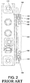
FIG. 2 is a cross-section view illustrating the slide rail assembly according to prior art; -
FIG. 3 is a diagram illustrating the slide rail assembly with the slide rail support structure being mounted on a rack and in an extended state according to prior art; -
FIG. 4 is a diagram illustrating a slide rail assembly according to an embodiment of the present invention; -
FIG. 5 is an exploded view illustrating the slide rail assembly according to the embodiment of the present invention; -
FIG. 6 is a diagram illustrating the slide rail assembly according including a first rail, a bracket device and at least one function member according to the embodiment of the present invention; -
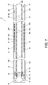
FIG. 7 is a diagram illustrating the slide rail assembly being in a retracted state according to the embodiment of the present invention; -
FIG. 8 is a diagram illustrating the slide rail assembly being in an extended state according to the embodiment of the present invention; -
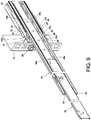
FIG. 9 is a diagram illustrating the slide rail assembly being mounted on a rack in the extended state according to the embodiment of the present invention; and -
FIG. 10 is a cross-section view illustrating the slide rail assembly according to the embodiment of the present invention. - As shown in
FIG. 4 andFIG. 5 , aslide rail assembly 20 of an embodiment of the present invention includes afirst rail 22, asecond rail 24, a slidingauxiliary device 26 and at least one function member (such as afirst function member 28 and a second function member 30) . Preferably, theslide rail assembly 20 further includes athird rail 32 and abracket device 33. - The
first rail 22 has afirst end portion 22a and asecond end portion 22b (such as a front end portion and a rear end portion, but the present invention is not limited). Thefirst rail 22 includes afirst wall 34a, asecond wall 34b and a firstlongitudinal wall 36 connected between thefirst wall 34a and thesecond wall 34b. Apassage 38 is defined by thefirst wall 34a, thesecond wall 34b and the firstlongitudinal wall 36. - The
second rail 24 is movably mounted in thepassage 38 of thefirst rail 22. Thesecond rail 24 includes athird wall 40a, afourth wall 40b and a secondlongitudinal wall 42 connected between thethird wall 40a and thefourth wall 40b. A passage is defined by thethird wall 40a, thefourth wall 40b and the secondlongitudinal wall 42. Thethird rail 32 is movably mounted in the passage of thesecond rail 24. - The sliding
auxiliary device 26 is arranged in thepassage 38 of thefirst rail 22. The slidingauxiliary device 26 includes a plurality ofrolling members 44 configured to improve the smoothness of the movement between thesecond rail 24 and thefirst rail 22. For example, the slidingauxiliary device 26 includes a first slidingauxiliary portion 26a and a second slidingauxiliary portion 26b. The first slidingauxiliary portion 26a and the second slidingauxiliary portion 26b respectively include a plurality of lowerrolling balls 44 and a plurality of upper rolling balls 44 (please refer toFIG. 7 andFIG. 8 ). - As shown in
FIG. 5 andFIG. 6 , thefirst function member 28 and thesecond function member 30 are fixedly arranged on thefirst rail 22 and located adjacent to an end portion of the first rail 22 (e.g. thefirst end portion 22a). Preferably, thefirst function member 28 and thesecond function member 30 both include metal material. Thefirst function member 28 is arranged adjacent to thefirst wall 34a of thefirst rail 22, and thesecond function member 30 is arranged adjacent to thesecond wall 34b of thefirst rail 22. Thefirst function member 28 and thesecond function member 30 are connected to thefirst rail 22 by substantially a same connecting method. Thefirst function member 28 and thesecond function member 30 have substantially a same structural configuration. - Taking the
first function member 28 as an example, thefirst function member 28 and thefirst rail 22 respectively have a first connectingportion 46 and a second connectingportion 48 corresponding to the first connectingportion 46. The first connectingportion 46 and the second connectingportion 48 are configured to be connected to each other. In the present embodiment, the first connectingportion 46 and the second connectingportion 48 are connected by engaging or fastening. In some embodiment, the first connectingportion 46 and the second connectingportion 48 may be connected by riveting or welding, but the present invention is not limited thereto. Furthermore, thefirst function member 28 includes afirst function portion 50 and asecond function portion 52. Hereinafter, it is illustrative of an example that thefirst function portion 50 and thesecond function portion 52 are connected by integrated together. - The first connecting
portion 46 is arranged on thefirst function portion 50, but the present invention is not limited thereto specifically. Thefirst function portion 50 is located in thepassage 38 of thefirst rail 22. Thesecond function portion 52 exceeds thefirst end portion 22a of thefirst rail 22 and located at outside of thepassage 38 of thefirst rail 22. - The
bracket device 33 is connected to thefirst rail 22 and located adjacent to thefirst end portion 22a of thefirst rail 22. Thebracket device 33 includes a first supportingwall 54a, a second supportingwall 54b and aside wall 56 connected between the first supportingwall 54a and the second supportingwall 54b. The first supportingwall 54a is configured to support thefirst wall 34a of thefirst rail 22 and thesecond function portion 52 of thefirst function member 28. The second supportingwall 54b is configured to support thesecond wall 34b of thefirst rail 22 and thesecond function portion 52 of thesecond function member 30. - Preferably, the first supporting
wall 54a of thebracket device 33 and thesecond function portion 52 of thefirst function member 28 respectively have afirst feature 58 and asecond feature 60 corresponding to thefirst feature 58. The second supportingwall 54b of thebracket device 33 and thesecond function portion 52 of thesecond function member 30 respectively have athird feature 62 and afourth feature 64 corresponding to thethird feature 62. In the present embodiment, the structure of thefirst feature 58 and thesecond feature 60 is a combination of concave and convex structures engaged with each other, such that the first supportingwall 54a and thesecond function portion 52 of thefirst function member 28 are able to be supported by or engaged with each other. Similarly, the structure of thethird feature 62 and thefourth feature 64 is also a combination of concave and convex structures engaged with each other, such that the second supportingwall 54b and thesecond function portion 52 of thesecond function member 30 are able to be supported by or engaged with each other. - Preferably, the
bracket device 33 further includes anend wall 66 substantially bent perpendicularly relative to theside wall 56. At least one mountingmember 68 is arranged on theend wall 66. The at least one mountingmember 68 is configured to mount thefirst rail 22 on a rack. - As shown in
FIG. 7 , theslide rail assembly 20 is in a retracted state. Wherein, thesecond rail 24 is located at a first predetermined position P1 (such as a retracted position, but not limited thereto) relative to thefirst rail 22, and thethird rail 32 is retracted relative to thesecond rail 24, and the sliding auxiliary device 26 (such as the first slidingauxiliary portion 26a and the second slidingauxiliary portion 26b) is located at a first sliding auxiliary position K1. In addition, the plurality of lower rollingballs 44 of the first slidingauxiliary portion 26a of the slidingauxiliary device 26 is configured to support between thefirst wall 34a of thefirst rail 22 and thethird wall 40a of thesecond rail 24. The plurality of upper rollingballs 44 of the second slidingauxiliary portion 26b of the slidingauxiliary device 26 is configured to support between thesecond wall 34b of thefirst rail 22 and thefourth wall 40b of thesecond rail 24. - Preferably, the
first rail 22 further includes at least one blockingportion 70 adjacent to thesecond end portion 22b of thefirst rail 22. The at least one blockingportion 70 is configured to prevent thesecond rail 24 from being moved along a second direction (e.g. a retracing direction) and detached from thefirst rail 22. - Preferably, the
second rail 24 further includes at least one pushing portion. For example, thesecond rail 24 includes a first pushingportion 72a and a second pushingportion 72b corresponding to the first slidingauxiliary portion 26a of the slidingauxiliary device 26 and the second slidingauxiliary portion 26b. - As shown in
FIG. 7 andFIG. 8 , when thesecond rail 24 is moved from the first predetermined position P1 along a first direction D1 (such as a extending direction) and a rail section X of thesecond rail 24 exceeds thefirst end portion 22a of thefirst rail 22 and is located at outside of thepassage 38 of thefirst rail 22, thesecond function portion 52 of the at least one function member (such as the first function member 28) is able to be configured to support at least one part of the rail section X of thesecond rail 24. In addition, thefirst function portion 50 of the at least one function member (such as the first function member 28) is configured to prevent the slidingauxiliary device 26 from being moved from inside of thepassage 38 of thefirst rail 22 to the outside of thepassage 38 of thefirst rail 22. Specifically, when thesecond rail 24 is moved from the first predetermined position P1 along the first direction D1 to a second predetermined position P2 (such as an extended position, but not limited thereto), the slidingauxiliary device 26 is pushed by the at least one pushing portion (i.e., the first pushingportion 72a and the second pushingportion 72b) to be moved from the first sliding auxiliary position K1 along the first direction D1 to a second sliding auxiliary position K2 (as shown inFIG. 8 ) and thefirst function portion 50 of the at least one function member (such as thefirst function member 28 and the second function member 30) is able to block the sliding auxiliary device 26(for example, to block the first slidingauxiliary portion 26a and the second slidingauxiliary portion 26b) to stop at the second sliding auxiliary position K2, in order to prevent the slidingauxiliary device 26 from being moved from the inside thepassage 38 of thefirst rail 22 to the outside of thepassage 38 of thefirst rail 22. - Preferably, when the
second rail 24 is moved from the first predetermined position P1 along the first direction D1 to the second predetermined position P2 and theslide rail assembly 20 is in an extending state and the rail section X of thesecond rail 24 exceeds thefirst end portion 22a of thefirst rail 22 and be located at the outside of thepassage 38 of thefirst rail 22, thesecond function portion 52 of thefirst function member 28 and thesecond function portion 52 of thesecond function member 30 are respectively configured to support thethird wall 40a of the rail section X of thesecond rail 24 and at least one part of thefourth wall 40b (as shown inFIG. 8 ). - Preferably, when the
second rail 24 is moved from the first predetermined position P1 along the first direction D1 to the second predetermined position P2, two ends (such as a front end and a rear end) of the first slidingauxiliary portion 26a respectively abut against thefirst function portion 50 of thefirst function member 28 and the first pushingportion 72a of thesecond rail 24, two ends (such as a front end and a rear end) of the second slidingauxiliary portion 26b respectively abut against thefirst function portion 50 of thesecond function member 30 and the second pushingportion 72b of the second rail 24 (as shown inFIG. 8 ). - As shown in
FIG. 9 , the at least one mountingmember 68 of thebracket device 33 is configured to mount thefirst rail 22 to apost 74 of a rack. Wherein, theslide rail assembly 20 is in the extending state. The structure configuration of theslide rail assembly 20 in the extending state is shown inFIG. 8 . For simplification, no further illustration is provided. - As shown in
FIG. 10 , a cross-section of thefirst function member 28 and a cross-section of thesecond function member 30 both include a first supportingsection 76 and a second supportingsection 78. The first supportingsection 76 and the second supportingsection 78 of thefirst function member 28 are respectively configured to correspond to afirst ball groove 80a of thefirst wall 34a of thefirst rail 22 and asecond ball groove 80b of thethird wall 40a of the second rail 24 (for example, the supporting section and the ball groove support each other). The first supportingsection 76 and the second supportingsection 78 of thesecond function member 30 are respectively configured to correspond to athird ball groove 80c of thesecond wall 34b of thefirst rail 22 and afourth ball groove 80d of thefourth wall 40b of the second rail 24(for example, the supporting section and the ball groove support each other). - Compared to the prior art, the
slide rail assembly 20 of the present embodiment has advantages over the prior art by the following perspectives: - 1. Comparing to a
gap 124 being formed between the supportingmember 120 and thefirst blocking base 110 in the prior art (please refer toFIG. 1 orFIG. 3 ), thefirst function portion 50 of the at least one function member of the embodiment of the present invention (such as thefirst function member 28 or the second function member 30) is located in thepassage 38 of thefirst rail 22. Thesecond function portion 52 is extended from thefirst function portion 50 and exceeds theend portion 22a of thefirst rail 22 and be located at the outside of thepassage 38 of thefirst rail 22. Therefore, the at least one function member (such as thefirst function member 28 or the second function member 30) has improved structural strength. Wherein, when thesecond rail 24 is located on the second predetermined position P2, thesecond function portion 52 of the at least one function member is able to be configured to support at least one part of the rail section X of thesecond rail 24, thefirst function portion 50 of the at least one function member is able to be configured to block and to prevent the slidingauxiliary device 26 from being moved from the inside of thepassage 38 of thefirst rail 22 to the outside of thepassage 38 of thefirst rail 22. - 2. The first supporting
wall 54a of thebracket device 33 is configured to support thefirst wall 34a of thefirst rail 22 and thesecond function portion 52 of thefirst function member 28. The second supportingwall 54b of thebracket device 33 is configured to support thesecond wall 34b of thefirst rail 22 and thesecond function portion 52 of thesecond function member 30. As such, thebracket device 33, thefirst rail 22 and the at least one function member (such as thefirst function member 28 and the second function member 30) are able to support each other and improve strength of structure. - 3. Extra materials can be reduced and the cost of inventory management can also be reduced.
Claims (12)
- A slide rail assembly (20), comprising:a first rail (22) comprising a first wall (34a), a second wall (34b) and a first longitudinal wall (36) connected between the first wall (34a) and the second wall (34b), a passage (38) being defined by the first wall (34a), the second wall (34b) and the first longitudinal wall (36);a second rail (24) movably mounted in the passage (38) of the first rail (22);a sliding auxiliary device (26) arranged in the passage (38) of the first rail (22), the sliding auxiliary device (26) comprising a plurality of rolling members (44) configured to support between the first rail (22) and the second rail (24) ; andcharacterized by:a first function member (28) arranged on the first rail (22) and adjacent to an end portion (22a) of the first rail (22) and the first wall (34a), wherein the first function member (28) comprises a first function portion (50) and a second function portion (52), the first function portion (50) is located in the passage (38) of the first rail (22), the second function portion (52) exceeds the end portion (22a) of the first rail (22) and located at outside of the passage (38) of the first rail (22);wherein when the second rail (24) is moved from a first predetermined position along a first direction and a rail section (X) of the second rail (24) exceeds the end portion (22a) the first rail (22) and is located at the outside of the passage (38) of the first rail (22), the second function portion (52) of the first function member (28) is configured to support a part of the rail section (X) of the second rail (24) ;wherein the first function portion (50) of the first function member (28) is configured to prevent the sliding auxiliary device (26) from being moved from the passage (38) of the first rail (22) to the outside of the passage (38) of the first rail (22) .
- The slide rail assembly (20) of claim 1, characterized in that the second rail (24) comprises at least one pushing portion (72a, 72b), when the second rail (24) is moved from the first predetermined position along the first direction to a second predetermined position, the sliding auxiliary device (26) is pushed by the at least one pushing portion (72a, 72b) of the second rail (24) and moved from a first sliding auxiliary position to a second sliding auxiliary position and the first function portion (50) of the first function member (28) is able to block the sliding auxiliary device (26) to stop at the second sliding auxiliary position, in order to prevent the sliding auxiliary device (26) from being moved from the passage (38) of the first rail (22) to the outside of the passage (38) of the first rail (22).
- The slide rail assembly (20) of claim 1 or 2, characterized in that the first function portion (50) and the second function portion (52) of the first function member (28) are integrated on one component.
- The slide rail assembly (20) of any of claims 1-3, characterized in that the second rail (24) comprises a third wall (40a), a fourth wall (40b) and a second longitudinal wall connected between the third wall (40a) and the fourth wall (40b), the slide rail assembly (20) further comprises a second function member (30), the second function member (30) is arranged on the first rail (22) adjacent to the end portion (22a) of the first rail (22) and the second wall (34b), when the second rail (24) is moved from the first predetermined position along the first direction and the rail section (X) of the second rail (24) exceeds the end portion (22a) of the first rail (22) and is located at the outside of the passage (38) of the first rail (22), the second function portion (52) of the first function member (28) and the second function portion (52) of the second function member (30) are configured to respectively support at least one part of the third wall (40a) and the fourth wall (40b) of the rail section (X) of the second rail (24).
- The slide rail assembly (20) of claim 4, characterized in that the plurality of rolling members (44) of the sliding auxiliary device (26) comprises at least one lower rolling ball (44) and at least one upper rolling ball (44), the at least one lower rolling ball (44) is configured to support between the first wall (34a) of the first rail (22) and the third wall (40a) of the second rail (24), the at least one upper rolling ball (44) is configured to support between the second wall (34b) of the first rail (22) and the fourth wall (40b) of the second rail (24).
- The slide rail assembly (20) of claim 5, characterized in that a cross-section of the first function member (28) comprises a first supporting section (76) and a second supporting section (78), and a cross-section of the second function member (30) comprises a first supporting section (76) and a second supporting section (78), the first supporting section (76) and the second supporting section (78) of the first function member (28) are respectively configured to correspond to a ball groove (80a) of the first wall (34a) of the first rail (22) and a ball groove (80b) of the third wall (40a) of the second rail (24), the first supporting section (76) and the second supporting section (78) of the second function member (30) are respectively configured to correspond to a ball groove (80c) of the second wall (34b) of the first rail (22) and a ball groove (80d) of the fourth wall (40b) of the second rail (24) .
- The slide rail assembly (20) of any of claims 4-6, further characterized by a bracket device (33), wherein the bracket device (33) is connected to the first rail (22) and adjacent to the end portion (22a) of the first rail (22), the bracket device (33) comprises a first supporting wall (54a), a second supporting wall (54b) and a side wall (56) connected between the first supporting wall (54a) and the second supporting wall (54b), the first supporting wall (54a) is configured to support the first wall (34a) of the first rail (22) and the second function portion (52) of the first function member (28), the second supporting wall (54b) is configured to support the second wall (34b) of the first rail (22) and the second function portion (52) of the second function member (30).
- The slide rail assembly (20) of claim 7, characterized in that the first supporting wall (54a) of the bracket device (33) has a first feature (58), the second function portion (52) of the first function member (28) has a second feature (60), the first feature (58) and the second feature (60) correspond to each other.
- The slide rail assembly (20) of claim 8, characterized in that the second supporting wall (54b) of the bracket device (33) has a third feature (62), the second function portion (52) of the second function member (30) has a fourth feature (64), the third feature (62) and the fourth feature (64) correspond to each other.
- The slide rail assembly (20) of any of claims 7-9, characterized in that the bracket device (33) further comprises at least one mounting member (68), the at least one mounting member (68) is configured to mount the first rail (22) to a rack.
- The slide rail assembly (20) of any of claims 1-10, further characterized by a third rail (32) movably mounted in a passage of the second rail (24).
- The slide rail assembly (20) of any of claims 1-11, characterized in that material of the first function member (28) is metal material.
Applications Claiming Priority (1)
| Application Number | Priority Date | Filing Date | Title |
|---|---|---|---|
| TW109116610A TWI714506B (en) | 2020-05-18 | 2020-05-18 | Slide rail assembly |
Publications (2)
| Publication Number | Publication Date |
|---|---|
| EP3914057A1 true EP3914057A1 (en) | 2021-11-24 |
| EP3914057B1 EP3914057B1 (en) | 2023-05-03 |
Family
ID=73343808
Family Applications (1)
| Application Number | Title | Priority Date | Filing Date |
|---|---|---|---|
| EP20206662.7A Active EP3914057B1 (en) | 2020-05-18 | 2020-11-10 | Slide rail assembly |
Country Status (4)
| Country | Link |
|---|---|
| US (1) | US11497310B2 (en) |
| EP (1) | EP3914057B1 (en) |
| JP (1) | JP6980086B2 (en) |
| TW (1) | TWI714506B (en) |
Families Citing this family (2)
| Publication number | Priority date | Publication date | Assignee | Title |
|---|---|---|---|---|
| TWI866605B (en) * | 2023-11-14 | 2024-12-11 | 富世達股份有限公司 | Slide device |
| TWI885803B (en) * | 2024-03-14 | 2025-06-01 | 南俊國際股份有限公司 | Reinforced rail assembly |
Citations (4)
| Publication number | Priority date | Publication date | Assignee | Title |
|---|---|---|---|---|
| EP2777431B1 (en) | 2013-03-12 | 2016-03-09 | King Slide Works Co., Ltd. | Support structure for support bracket and rail |
| US20160278232A1 (en) * | 2015-03-19 | 2016-09-22 | King Slide Works Co., Ltd. | Slide rail assembly |
| EP3253188A1 (en) * | 2016-05-31 | 2017-12-06 | King Slide Works Co., Ltd. | Slide rail assembly |
| EP3620080A1 (en) * | 2018-09-10 | 2020-03-11 | King Slide Works Co., Ltd. | Slide rail assembly |
Family Cites Families (12)
| Publication number | Priority date | Publication date | Assignee | Title |
|---|---|---|---|---|
| TW491056U (en) * | 2001-01-08 | 2002-06-11 | Kuo-Chan Weng | Guide structure of extensible rail assembly |
| TWI261510B (en) * | 2005-08-22 | 2006-09-11 | King Slide Works Co Ltd | Positioning device for drawer slide |
| US7918517B2 (en) * | 2007-10-12 | 2011-04-05 | King Slide Works Co., Ltd. | Locating structure for a slide assembly |
| TWI417070B (en) | 2011-01-21 | 2013-12-01 | King Slide Works Co Ltd | Slide assembly with bumper |
| US8485616B2 (en) | 2011-02-09 | 2013-07-16 | King Slide Works Co., Ltd. | Slide assembly with buffering member for reducing impact and noise |
| TWI461164B (en) * | 2011-08-19 | 2014-11-21 | King Slide Works Co Ltd | Slide assembly with positioning mechanism |
| US20140265786A1 (en) | 2013-03-13 | 2014-09-18 | King Slide Technology Co., Ltd. | Support structure for support bracket and rail |
| JP3196235U (en) | 2013-12-19 | 2015-02-26 | ハーン・マーケティング・エスディエヌ・ビーエイチディ | Slide guide rail system |
| US9474182B1 (en) | 2015-03-26 | 2016-10-18 | King Slide Works Co., Ltd. | Slide rail assembly |
| TWI536933B (en) | 2015-11-12 | 2016-06-11 | 川湖科技股份有限公司 | Slide rail assembly |
| TWI592791B (en) * | 2016-04-13 | 2017-07-21 | Server slide reinforcement structure | |
| TWI670029B (en) | 2018-03-08 | 2019-09-01 | 川湖科技股份有限公司 | Slide rail assembly |
-
2020
- 2020-05-18 TW TW109116610A patent/TWI714506B/en active
- 2020-10-05 US US17/063,684 patent/US11497310B2/en active Active
- 2020-11-10 EP EP20206662.7A patent/EP3914057B1/en active Active
- 2020-12-11 JP JP2020205538A patent/JP6980086B2/en active Active
Patent Citations (4)
| Publication number | Priority date | Publication date | Assignee | Title |
|---|---|---|---|---|
| EP2777431B1 (en) | 2013-03-12 | 2016-03-09 | King Slide Works Co., Ltd. | Support structure for support bracket and rail |
| US20160278232A1 (en) * | 2015-03-19 | 2016-09-22 | King Slide Works Co., Ltd. | Slide rail assembly |
| EP3253188A1 (en) * | 2016-05-31 | 2017-12-06 | King Slide Works Co., Ltd. | Slide rail assembly |
| EP3620080A1 (en) * | 2018-09-10 | 2020-03-11 | King Slide Works Co., Ltd. | Slide rail assembly |
Also Published As
| Publication number | Publication date |
|---|---|
| US20210353061A1 (en) | 2021-11-18 |
| JP6980086B2 (en) | 2021-12-15 |
| US11497310B2 (en) | 2022-11-15 |
| JP2021180830A (en) | 2021-11-25 |
| TWI714506B (en) | 2020-12-21 |
| EP3914057B1 (en) | 2023-05-03 |
| TW202143887A (en) | 2021-12-01 |
Similar Documents
| Publication | Publication Date | Title |
|---|---|---|
| EP3352547B1 (en) | Slide rail assembly | |
| US10765207B2 (en) | Slide rail assembly and bracket device thereof | |
| EP3637968B1 (en) | Cable management assembly | |
| EP3914057B1 (en) | Slide rail assembly | |
| EP3397035A1 (en) | Slide rail assembly | |
| EP3253188B1 (en) | Slide rail assembly | |
| US9861197B2 (en) | Slide rail assembly | |
| EP3298929B1 (en) | Slide rail assembly | |
| EP3644695B1 (en) | Slide rail assembly | |
| US6547081B1 (en) | Slide assembly for use in a rack assembly | |
| EP4570126A1 (en) | Slide rail assembly | |
| US12042045B2 (en) | Slide rail assembly | |
| EP3310033B1 (en) | Slide rail assembly | |
| CN116548753B (en) | Slide rail assembly | |
| EP4057786B1 (en) | Slide rail mechanism and slide rail kit thereof | |
| EP4666911A1 (en) | Slide rail assembly | |
| EP3772242B1 (en) | Slide rail assembly and bracket device thereof | |
| EP3419397B1 (en) | Slide rail assembly | |
| EP3993583B1 (en) | Slide rail assembly | |
| CN113693388A (en) | Sliding rail assembly | |
| CN111972885B (en) | Slide rail assembly | |
| CN121751549A (en) | Sliding rail device |
Legal Events
| Date | Code | Title | Description |
|---|---|---|---|
| PUAI | Public reference made under article 153(3) epc to a published international application that has entered the european phase |
Free format text: ORIGINAL CODE: 0009012 |
|
| STAA | Information on the status of an ep patent application or granted ep patent |
Free format text: STATUS: THE APPLICATION HAS BEEN PUBLISHED |
|
| STAA | Information on the status of an ep patent application or granted ep patent |
Free format text: STATUS: REQUEST FOR EXAMINATION WAS MADE |
|
| AK | Designated contracting states |
Kind code of ref document: A1 Designated state(s): AL AT BE BG CH CY CZ DE DK EE ES FI FR GB GR HR HU IE IS IT LI LT LU LV MC MK MT NL NO PL PT RO RS SE SI SK SM TR |
|
| B565 | Issuance of search results under rule 164(2) epc |
Effective date: 20210504 |
|
| 17P | Request for examination filed |
Effective date: 20211103 |
|
| RBV | Designated contracting states (corrected) |
Designated state(s): AL AT BE BG CH CY CZ DE DK EE ES FI FR GB GR HR HU IE IS IT LI LT LU LV MC MK MT NL NO PL PT RO RS SE SI SK SM TR |
|
| GRAP | Despatch of communication of intention to grant a patent |
Free format text: ORIGINAL CODE: EPIDOSNIGR1 |
|
| STAA | Information on the status of an ep patent application or granted ep patent |
Free format text: STATUS: GRANT OF PATENT IS INTENDED |
|
| INTG | Intention to grant announced |
Effective date: 20221129 |
|
| GRAS | Grant fee paid |
Free format text: ORIGINAL CODE: EPIDOSNIGR3 |
|
| GRAA | (expected) grant |
Free format text: ORIGINAL CODE: 0009210 |
|
| STAA | Information on the status of an ep patent application or granted ep patent |
Free format text: STATUS: THE PATENT HAS BEEN GRANTED |
|
| AK | Designated contracting states |
Kind code of ref document: B1 Designated state(s): AL AT BE BG CH CY CZ DE DK EE ES FI FR GB GR HR HU IE IS IT LI LT LU LV MC MK MT NL NO PL PT RO RS SE SI SK SM TR |
|
| REG | Reference to a national code |
Ref country code: GB Ref legal event code: FG4D |
|
| REG | Reference to a national code |
Ref country code: AT Ref legal event code: REF Ref document number: 1565792 Country of ref document: AT Kind code of ref document: T Effective date: 20230515 Ref country code: CH Ref legal event code: EP |
|
| REG | Reference to a national code |
Ref country code: DE Ref legal event code: R096 Ref document number: 602020010361 Country of ref document: DE |
|
| REG | Reference to a national code |
Ref country code: IE Ref legal event code: FG4D |
|
| REG | Reference to a national code |
Ref country code: LT Ref legal event code: MG9D |
|
| REG | Reference to a national code |
Ref country code: NL Ref legal event code: MP Effective date: 20230503 |
|
| REG | Reference to a national code |
Ref country code: AT Ref legal event code: MK05 Ref document number: 1565792 Country of ref document: AT Kind code of ref document: T Effective date: 20230503 |
|
| PG25 | Lapsed in a contracting state [announced via postgrant information from national office to epo] |
Ref country code: SE Free format text: LAPSE BECAUSE OF FAILURE TO SUBMIT A TRANSLATION OF THE DESCRIPTION OR TO PAY THE FEE WITHIN THE PRESCRIBED TIME-LIMIT Effective date: 20230503 Ref country code: PT Free format text: LAPSE BECAUSE OF FAILURE TO SUBMIT A TRANSLATION OF THE DESCRIPTION OR TO PAY THE FEE WITHIN THE PRESCRIBED TIME-LIMIT Effective date: 20230904 Ref country code: NO Free format text: LAPSE BECAUSE OF FAILURE TO SUBMIT A TRANSLATION OF THE DESCRIPTION OR TO PAY THE FEE WITHIN THE PRESCRIBED TIME-LIMIT Effective date: 20230803 Ref country code: NL Free format text: LAPSE BECAUSE OF FAILURE TO SUBMIT A TRANSLATION OF THE DESCRIPTION OR TO PAY THE FEE WITHIN THE PRESCRIBED TIME-LIMIT Effective date: 20230503 Ref country code: ES Free format text: LAPSE BECAUSE OF FAILURE TO SUBMIT A TRANSLATION OF THE DESCRIPTION OR TO PAY THE FEE WITHIN THE PRESCRIBED TIME-LIMIT Effective date: 20230503 Ref country code: AT Free format text: LAPSE BECAUSE OF FAILURE TO SUBMIT A TRANSLATION OF THE DESCRIPTION OR TO PAY THE FEE WITHIN THE PRESCRIBED TIME-LIMIT Effective date: 20230503 |
|
| PG25 | Lapsed in a contracting state [announced via postgrant information from national office to epo] |
Ref country code: RS Free format text: LAPSE BECAUSE OF FAILURE TO SUBMIT A TRANSLATION OF THE DESCRIPTION OR TO PAY THE FEE WITHIN THE PRESCRIBED TIME-LIMIT Effective date: 20230503 Ref country code: PL Free format text: LAPSE BECAUSE OF FAILURE TO SUBMIT A TRANSLATION OF THE DESCRIPTION OR TO PAY THE FEE WITHIN THE PRESCRIBED TIME-LIMIT Effective date: 20230503 Ref country code: LV Free format text: LAPSE BECAUSE OF FAILURE TO SUBMIT A TRANSLATION OF THE DESCRIPTION OR TO PAY THE FEE WITHIN THE PRESCRIBED TIME-LIMIT Effective date: 20230503 Ref country code: LT Free format text: LAPSE BECAUSE OF FAILURE TO SUBMIT A TRANSLATION OF THE DESCRIPTION OR TO PAY THE FEE WITHIN THE PRESCRIBED TIME-LIMIT Effective date: 20230503 Ref country code: IS Free format text: LAPSE BECAUSE OF FAILURE TO SUBMIT A TRANSLATION OF THE DESCRIPTION OR TO PAY THE FEE WITHIN THE PRESCRIBED TIME-LIMIT Effective date: 20230903 Ref country code: HR Free format text: LAPSE BECAUSE OF FAILURE TO SUBMIT A TRANSLATION OF THE DESCRIPTION OR TO PAY THE FEE WITHIN THE PRESCRIBED TIME-LIMIT Effective date: 20230503 Ref country code: GR Free format text: LAPSE BECAUSE OF FAILURE TO SUBMIT A TRANSLATION OF THE DESCRIPTION OR TO PAY THE FEE WITHIN THE PRESCRIBED TIME-LIMIT Effective date: 20230804 |
|
| PG25 | Lapsed in a contracting state [announced via postgrant information from national office to epo] |
Ref country code: FI Free format text: LAPSE BECAUSE OF FAILURE TO SUBMIT A TRANSLATION OF THE DESCRIPTION OR TO PAY THE FEE WITHIN THE PRESCRIBED TIME-LIMIT Effective date: 20230503 |
|
| PG25 | Lapsed in a contracting state [announced via postgrant information from national office to epo] |
Ref country code: SK Free format text: LAPSE BECAUSE OF FAILURE TO SUBMIT A TRANSLATION OF THE DESCRIPTION OR TO PAY THE FEE WITHIN THE PRESCRIBED TIME-LIMIT Effective date: 20230503 |
|
| PG25 | Lapsed in a contracting state [announced via postgrant information from national office to epo] |
Ref country code: SM Free format text: LAPSE BECAUSE OF FAILURE TO SUBMIT A TRANSLATION OF THE DESCRIPTION OR TO PAY THE FEE WITHIN THE PRESCRIBED TIME-LIMIT Effective date: 20230503 Ref country code: SK Free format text: LAPSE BECAUSE OF FAILURE TO SUBMIT A TRANSLATION OF THE DESCRIPTION OR TO PAY THE FEE WITHIN THE PRESCRIBED TIME-LIMIT Effective date: 20230503 Ref country code: RO Free format text: LAPSE BECAUSE OF FAILURE TO SUBMIT A TRANSLATION OF THE DESCRIPTION OR TO PAY THE FEE WITHIN THE PRESCRIBED TIME-LIMIT Effective date: 20230503 Ref country code: EE Free format text: LAPSE BECAUSE OF FAILURE TO SUBMIT A TRANSLATION OF THE DESCRIPTION OR TO PAY THE FEE WITHIN THE PRESCRIBED TIME-LIMIT Effective date: 20230503 Ref country code: DK Free format text: LAPSE BECAUSE OF FAILURE TO SUBMIT A TRANSLATION OF THE DESCRIPTION OR TO PAY THE FEE WITHIN THE PRESCRIBED TIME-LIMIT Effective date: 20230503 Ref country code: CZ Free format text: LAPSE BECAUSE OF FAILURE TO SUBMIT A TRANSLATION OF THE DESCRIPTION OR TO PAY THE FEE WITHIN THE PRESCRIBED TIME-LIMIT Effective date: 20230503 |
|
| REG | Reference to a national code |
Ref country code: DE Ref legal event code: R097 Ref document number: 602020010361 Country of ref document: DE |
|
| PLBE | No opposition filed within time limit |
Free format text: ORIGINAL CODE: 0009261 |
|
| STAA | Information on the status of an ep patent application or granted ep patent |
Free format text: STATUS: NO OPPOSITION FILED WITHIN TIME LIMIT |
|
| 26N | No opposition filed |
Effective date: 20240206 |
|
| PG25 | Lapsed in a contracting state [announced via postgrant information from national office to epo] |
Ref country code: SI Free format text: LAPSE BECAUSE OF FAILURE TO SUBMIT A TRANSLATION OF THE DESCRIPTION OR TO PAY THE FEE WITHIN THE PRESCRIBED TIME-LIMIT Effective date: 20230503 |
|
| PG25 | Lapsed in a contracting state [announced via postgrant information from national office to epo] |
Ref country code: SI Free format text: LAPSE BECAUSE OF FAILURE TO SUBMIT A TRANSLATION OF THE DESCRIPTION OR TO PAY THE FEE WITHIN THE PRESCRIBED TIME-LIMIT Effective date: 20230503 Ref country code: IT Free format text: LAPSE BECAUSE OF FAILURE TO SUBMIT A TRANSLATION OF THE DESCRIPTION OR TO PAY THE FEE WITHIN THE PRESCRIBED TIME-LIMIT Effective date: 20230503 |
|
| REG | Reference to a national code |
Ref country code: CH Ref legal event code: PL |
|
| PG25 | Lapsed in a contracting state [announced via postgrant information from national office to epo] |
Ref country code: MC Free format text: LAPSE BECAUSE OF FAILURE TO SUBMIT A TRANSLATION OF THE DESCRIPTION OR TO PAY THE FEE WITHIN THE PRESCRIBED TIME-LIMIT Effective date: 20230503 |
|
| PG25 | Lapsed in a contracting state [announced via postgrant information from national office to epo] |
Ref country code: LU Free format text: LAPSE BECAUSE OF NON-PAYMENT OF DUE FEES Effective date: 20231110 |
|
| PG25 | Lapsed in a contracting state [announced via postgrant information from national office to epo] |
Ref country code: CH Free format text: LAPSE BECAUSE OF NON-PAYMENT OF DUE FEES Effective date: 20231130 |
|
| PG25 | Lapsed in a contracting state [announced via postgrant information from national office to epo] |
Ref country code: MC Free format text: LAPSE BECAUSE OF FAILURE TO SUBMIT A TRANSLATION OF THE DESCRIPTION OR TO PAY THE FEE WITHIN THE PRESCRIBED TIME-LIMIT Effective date: 20230503 Ref country code: LU Free format text: LAPSE BECAUSE OF NON-PAYMENT OF DUE FEES Effective date: 20231110 Ref country code: CH Free format text: LAPSE BECAUSE OF NON-PAYMENT OF DUE FEES Effective date: 20231130 |
|
| REG | Reference to a national code |
Ref country code: BE Ref legal event code: MM Effective date: 20231130 |
|
| REG | Reference to a national code |
Ref country code: DE Ref legal event code: R082 Ref document number: 602020010361 Country of ref document: DE Representative=s name: STRAUS, ALEXANDER, DIPL.-CHEM.UNIV. DR.PHIL., DE |
|
| PG25 | Lapsed in a contracting state [announced via postgrant information from national office to epo] |
Ref country code: BE Free format text: LAPSE BECAUSE OF NON-PAYMENT OF DUE FEES Effective date: 20231130 |
|
| PG25 | Lapsed in a contracting state [announced via postgrant information from national office to epo] |
Ref country code: FR Free format text: LAPSE BECAUSE OF NON-PAYMENT OF DUE FEES Effective date: 20231130 |
|
| PG25 | Lapsed in a contracting state [announced via postgrant information from national office to epo] |
Ref country code: FR Free format text: LAPSE BECAUSE OF NON-PAYMENT OF DUE FEES Effective date: 20231130 Ref country code: BE Free format text: LAPSE BECAUSE OF NON-PAYMENT OF DUE FEES Effective date: 20231130 |
|
| PG25 | Lapsed in a contracting state [announced via postgrant information from national office to epo] |
Ref country code: BG Free format text: LAPSE BECAUSE OF FAILURE TO SUBMIT A TRANSLATION OF THE DESCRIPTION OR TO PAY THE FEE WITHIN THE PRESCRIBED TIME-LIMIT Effective date: 20230503 |
|
| PG25 | Lapsed in a contracting state [announced via postgrant information from national office to epo] |
Ref country code: BG Free format text: LAPSE BECAUSE OF FAILURE TO SUBMIT A TRANSLATION OF THE DESCRIPTION OR TO PAY THE FEE WITHIN THE PRESCRIBED TIME-LIMIT Effective date: 20230503 |
|
| PG25 | Lapsed in a contracting state [announced via postgrant information from national office to epo] |
Ref country code: CY Free format text: LAPSE BECAUSE OF FAILURE TO SUBMIT A TRANSLATION OF THE DESCRIPTION OR TO PAY THE FEE WITHIN THE PRESCRIBED TIME-LIMIT; INVALID AB INITIO Effective date: 20201110 |
|
| PG25 | Lapsed in a contracting state [announced via postgrant information from national office to epo] |
Ref country code: HU Free format text: LAPSE BECAUSE OF FAILURE TO SUBMIT A TRANSLATION OF THE DESCRIPTION OR TO PAY THE FEE WITHIN THE PRESCRIBED TIME-LIMIT; INVALID AB INITIO Effective date: 20201110 |
|
| PGFP | Annual fee paid to national office [announced via postgrant information from national office to epo] |
Ref country code: GB Payment date: 20250909 Year of fee payment: 6 |
|
| PGFP | Annual fee paid to national office [announced via postgrant information from national office to epo] |
Ref country code: IE Payment date: 20250909 Year of fee payment: 6 |
|
| PG25 | Lapsed in a contracting state [announced via postgrant information from national office to epo] |
Ref country code: TR Free format text: LAPSE BECAUSE OF FAILURE TO SUBMIT A TRANSLATION OF THE DESCRIPTION OR TO PAY THE FEE WITHIN THE PRESCRIBED TIME-LIMIT Effective date: 20230503 |
|
| PGFP | Annual fee paid to national office [announced via postgrant information from national office to epo] |
Ref country code: DE Payment date: 20250910 Year of fee payment: 6 |