EP3913808B1 - Split gain shape vector coding - Google Patents
Split gain shape vector coding Download PDFInfo
- Publication number
- EP3913808B1 EP3913808B1 EP21185475.7A EP21185475A EP3913808B1 EP 3913808 B1 EP3913808 B1 EP 3913808B1 EP 21185475 A EP21185475 A EP 21185475A EP 3913808 B1 EP3913808 B1 EP 3913808B1
- Authority
- EP
- European Patent Office
- Prior art keywords
- segments
- vector
- segment
- avg
- encoding
- Prior art date
- Legal status (The legal status is an assumption and is not a legal conclusion. Google has not performed a legal analysis and makes no representation as to the accuracy of the status listed.)
- Active
Links
Images


Classifications
-
- H—ELECTRICITY
- H03—ELECTRONIC CIRCUITRY
- H03M—CODING; DECODING; CODE CONVERSION IN GENERAL
- H03M7/00—Conversion of a code where information is represented by a given sequence or number of digits to a code where the same, similar or subset of information is represented by a different sequence or number of digits
- H03M7/30—Compression; Expansion; Suppression of unnecessary data, e.g. redundancy reduction
- H03M7/3082—Vector coding
-
- G—PHYSICS
- G10—MUSICAL INSTRUMENTS; ACOUSTICS
- G10L—SPEECH ANALYSIS TECHNIQUES OR SPEECH SYNTHESIS; SPEECH RECOGNITION; SPEECH OR VOICE PROCESSING TECHNIQUES; SPEECH OR AUDIO CODING OR DECODING
- G10L19/00—Speech or audio signals analysis-synthesis techniques for redundancy reduction, e.g. in vocoders; Coding or decoding of speech or audio signals, using source filter models or psychoacoustic analysis
- G10L19/002—Dynamic bit allocation
-
- G—PHYSICS
- G10—MUSICAL INSTRUMENTS; ACOUSTICS
- G10L—SPEECH ANALYSIS TECHNIQUES OR SPEECH SYNTHESIS; SPEECH RECOGNITION; SPEECH OR VOICE PROCESSING TECHNIQUES; SPEECH OR AUDIO CODING OR DECODING
- G10L19/00—Speech or audio signals analysis-synthesis techniques for redundancy reduction, e.g. in vocoders; Coding or decoding of speech or audio signals, using source filter models or psychoacoustic analysis
- G10L19/02—Speech or audio signals analysis-synthesis techniques for redundancy reduction, e.g. in vocoders; Coding or decoding of speech or audio signals, using source filter models or psychoacoustic analysis using spectral analysis, e.g. transform vocoders or subband vocoders
- G10L19/032—Quantisation or dequantisation of spectral components
- G10L19/038—Vector quantisation, e.g. TwinVQ audio
-
- G—PHYSICS
- G10—MUSICAL INSTRUMENTS; ACOUSTICS
- G10L—SPEECH ANALYSIS TECHNIQUES OR SPEECH SYNTHESIS; SPEECH RECOGNITION; SPEECH OR VOICE PROCESSING TECHNIQUES; SPEECH OR AUDIO CODING OR DECODING
- G10L19/00—Speech or audio signals analysis-synthesis techniques for redundancy reduction, e.g. in vocoders; Coding or decoding of speech or audio signals, using source filter models or psychoacoustic analysis
- G10L19/04—Speech or audio signals analysis-synthesis techniques for redundancy reduction, e.g. in vocoders; Coding or decoding of speech or audio signals, using source filter models or psychoacoustic analysis using predictive techniques
- G10L19/16—Vocoder architecture
- G10L19/18—Vocoders using multiple modes
- G10L19/22—Mode decision, i.e. based on audio signal content versus external parameters
-
- H—ELECTRICITY
- H04—ELECTRIC COMMUNICATION TECHNIQUE
- H04N—PICTORIAL COMMUNICATION, e.g. TELEVISION
- H04N19/00—Methods or arrangements for coding, decoding, compressing or decompressing digital video signals
- H04N19/10—Methods or arrangements for coding, decoding, compressing or decompressing digital video signals using adaptive coding
- H04N19/102—Methods or arrangements for coding, decoding, compressing or decompressing digital video signals using adaptive coding characterised by the element, parameter or selection affected or controlled by the adaptive coding
- H04N19/124—Quantisation
-
- G—PHYSICS
- G10—MUSICAL INSTRUMENTS; ACOUSTICS
- G10L—SPEECH ANALYSIS TECHNIQUES OR SPEECH SYNTHESIS; SPEECH RECOGNITION; SPEECH OR VOICE PROCESSING TECHNIQUES; SPEECH OR AUDIO CODING OR DECODING
- G10L15/00—Speech recognition
- G10L15/08—Speech classification or search
-
- H—ELECTRICITY
- H03—ELECTRONIC CIRCUITRY
- H03M—CODING; DECODING; CODE CONVERSION IN GENERAL
- H03M7/00—Conversion of a code where information is represented by a given sequence or number of digits to a code where the same, similar or subset of information is represented by a different sequence or number of digits
- H03M7/30—Compression; Expansion; Suppression of unnecessary data, e.g. redundancy reduction
-
- H—ELECTRICITY
- H04—ELECTRIC COMMUNICATION TECHNIQUE
- H04B—TRANSMISSION
- H04B1/00—Details of transmission systems, not covered by a single one of groups H04B3/00 - H04B13/00; Details of transmission systems not characterised by the medium used for transmission
- H04B1/66—Details of transmission systems, not covered by a single one of groups H04B3/00 - H04B13/00; Details of transmission systems not characterised by the medium used for transmission for reducing bandwidth of signals; for improving efficiency of transmission
- H04B1/665—Details of transmission systems, not covered by a single one of groups H04B3/00 - H04B13/00; Details of transmission systems not characterised by the medium used for transmission for reducing bandwidth of signals; for improving efficiency of transmission using psychoacoustic properties of the ear, e.g. masking effect
-
- H—ELECTRICITY
- H04—ELECTRIC COMMUNICATION TECHNIQUE
- H04N—PICTORIAL COMMUNICATION, e.g. TELEVISION
- H04N19/00—Methods or arrangements for coding, decoding, compressing or decompressing digital video signals
- H04N19/60—Methods or arrangements for coding, decoding, compressing or decompressing digital video signals using transform coding
- H04N19/61—Methods or arrangements for coding, decoding, compressing or decompressing digital video signals using transform coding in combination with predictive coding
Definitions
- the invention disclosed herein generally relates to gain shape vector encoding and decoding, and in particular to split gain shape vector quantization.
- Encoding methods for e.g. audio and/or video typically comprise some type of quantization of signal segments. It is known that unconstrained vector quantization (VQ) is a useful quantization method for grouped samples, i.e. vectors, of a certain length.
- VQ unconstrained vector quantization
- the memory and search complexity constraints have led to the development of structured vector quantizers. Different structures give different trade-offs in terms of search complexity and memory requirements.
- gain-shape vector quantization is to quantize a pair of gain and shape components ⁇ r, G ⁇ instead of directly quantizing the target vector.
- the gain and shape components are then encoded using a shape quantizer which is tuned for the normalized shape input, and a gain quantizer which handles the dynamics of the signal.
- This structure is commonly used in audio coding since the division into dynamics and shape, also denoted fine structure, fits well with the perceptual auditory model.
- audio codecs such as IETF Opus and ITU-T G.719 uses a gain-shape vector quantization to encode the spectral coefficients of the target audio signal. Both these codecs use a fixed band structure to partition the spectrum into multiple segments, and there is no adaptation of the band structure to any changes in the target vector.
- a concept of embodiments described herein is to analyze the shape and determine a suitable resolution into sub-vectors, given a target vector of a certain size. This may reduce the quantization error, and increase perceived quality, in case of audio codec. Further, it is an aim of some embodiments described herein to find an optimal number of sections, i.e. number of splits of the target vector.
- Embodiments herein relate to a method for supporting split gain shape vector encoding.
- the method is intended to be performed by a media encoder in situations where the encoding of each vector segment is subjected to a constraint related to a maximum number of bits, B MAX . That is, in situations where the maximum number of bits allowed for encoding of a vector segment is B MAX .
- This constraint may be due to e.g. processing capacity and/or memory capacity of the media encoder.
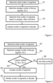
- a method according to an exemplifying embodiment will be described below with reference to figure 1 .
- the method illustrated in figure 1 comprises, for a target vector x, determining 101 an initial number, Np _init , of segments for the target vector x.
- the number Np _init could be determined based on e.g. B MAX and a bit budget, i.e. the number of bits allocated for encoding the entire vector x.
- the method further comprises determining 102 an average number of bits per segment, B AVG , based on the vector bit budget and Np _init . Note that the vector x need not actually be split on this stage, even though an initial number of segments and an average number of bits available for an initial vector segment have been determined.
- the method further comprises determining 103 a final number, Np, of segments to be used in the gain shape vector encoding, based on energies of the Np _init segments and a difference between B MAX and B AVG .
- determining a final number of segments By determining a final number of segments based on these paramters, an efficient allocation of the bits of the bit budget over the target vector is enabled, which will be described more in detail further below.
- the determining of a number of segments could alternatively be expressed as determining a number of splits, since the number of segments and the number of splits are closely related.
- the term split could be used to denote a segment.
- the determined final number, Np, of segments may then be indicated to a media decoder, in order to enable the media decoder to adequately decode the encoded gain shape vector. It should be noted that it is not necessarily the actual number of segments that is indicated, but rather a change as compared to the determined initial number of segments. Regarding the determining of Np _init , this initial number of segments may be given for the encoder and decoder. In such cases the term "determining" would refer e.g. to establishing Np _init for use, or similar.
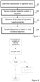
- the determining of a final number of segments comprises increasing 204 the number of segments (and splits) when a relation between the energies of the Np _init segments and the difference between B MAX and B AVG fulfills a criterion.
- increasing the number of segments is here meant increasing, as compared to the initial number Np _init , of segments.
- the increase of the number of segments could then be indicated 205 to a media decoder in a suitable manner. It is advantageous to use as few bits as possible for indicating the final number of segments to a decoder.
- the final increased number of segments could be indicated to the media decoder using a single bit, which is often referred to as a flag.
- the bit could be set to "1", or “true”, when an increased number of segments is applied, and be set to "0", or "false", when the initial number of segments is to be used. That is, the determining of a final number of segments may further comprise to determine 206 that the initial number, Np _init , of segments, should be used, i.e.
- Np Np _init when the relation between the energies of the Np _init segments and the difference between B MAX and B AVG does not fulfill the criterion, or, when a corresponding criterion is not met. This is illustrated as the action 206 in figure 2 .
- the determining of a final number, Np, of segments may comprise increasing 204 the number of segments, as compared to the initial number, for the target vector x, when a maximum deviation, of a target vector segment energy, from an average per-segment energy value, E AVG , for the target vector x is larger than a threshold based on the difference between B MAX and B AVG . That is, an energy variation over the target vector segments may be compared to a threshold based on the difference between B MAX and B AVG .
- E AVG The logic behind using a maximum deviation from an average per-segment energy value, E AVG is, described in a simplified manner, that when there are large deviations from an average per-segment energy, there are large differences in the perceptual importance of the different segments. It should be noted that the "threshold" comparison could be expressed the other way around, such that the difference between B MAX and B AVG is compared to a threshold, which depends on, or is based on the energies of the Np _init segments.
- the determining, or decision, of when to add an additional split may be based on testing whether the energy variation measure M is above a certain threshold based on B MAX and B AVG as:
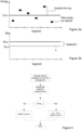
- Figure 3a illustrates a mean energy per segment (black dots) and total average energy E AVG (average of the segment averages). To minimize the coding distortion, it is desired to use more bits for encoding segments comprising more energy than for encoding segments comprising less energy. Thus, when there is large variation in energy between segments, it would be desired to reallocate bits from segments comprising less energy to segments comprising more energy, assuming that all segments initially are allocated at least approximately B AVG bits, i.e. assuming an initial even distribution of the bits over the segments.
- Figure 3b is a simple graph illustrating a number of segments, a B MAX value and a B AVG value.
- B MAX and B AVG which could also be denoted the headroom herein, are "small", e.g. smaller than a threshold, it will not be possible to reallocate that many bits to the high energy content segments, before reaching B MAX .
- B AVG will be reduced, which is illustrated by a dashed arrow in figure 3a , and thus increase the possibility to allocate more bits to high energy content segments.
- a higher positive deviation, in number of bits is allowed from B AVG , which enables reallocation of bits.
- the maximum allowed positive deviation is B MAX - B AVG .
- reallocation does not imply that an average number B AVG of bits is actually allocated to each segment before reallocating, but is only used to facilitate understanding of the solution provided herein.
- An exemplifying embodiment could be described as: when an energy variation between the vector segments is "large” in relation to a headroom, B MAX - B AVG , the number of splits and segments is increased by "1", which is then indicated to a decoder by the setting of a one-bit flag.
- the determining of "large” may be performed by use of a threshold value, which may be selected based on e.g. simulations.
- a threshold value which may be selected based on e.g. simulations.
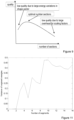
- FIG 4 the energy variation is denoted M, and in this example, the threshold M THR is based on B MAX - B AVG .
- Different examples of expressions for an energy variation will be described further below.
- a tuning parameter ⁇ may be used to make the decision threshold proportional to the headroom.
- a value of ⁇ may be derived e.g. based on simulations.
- the embodiments described above are intended to be non-recursive, which implies a low complexity. This may be advantageous, as compared to more resource-demanding recursive methods. It should further be note that the segments are intended to be at least approximately evenly distributed over the vector, i.e. be of, at least approximately, equal size. This may also be an advantage, as compared to methods generating segments of very different sizes.
- the decision for additional split is made on basis of: where ⁇ is a lower threshold for the increase in variance of the segment energies between two consecutive number of splits.
- ⁇ is a lower threshold for the increase in variance of the segment energies between two consecutive number of splits.
- the increase in variance is sufficient, i.e. in this example exceeds the threshold ⁇ , the number of segments is increased, e.g. by one.
- the use of an additional split could be signalled from the encoder to the decoder by, for example, using one bit for signalling one additional split or no additional split. However, more bits could be used for signalling more than one additional split if preferred.
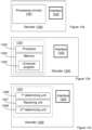
- FIG. 12a An exemplifying embodiment of a media encoder is illustrated in a general manner in figure 12a .
- media encoder is referred to an encoder for e.g. audio and/or video signals.
- the encoder 1200 is configured to perform at least one of the method embodiments described above with reference to any of figures 1-2 and 4 .
- the encoder 1200 is associated with the same technical features, objects and advantages as the previously described method embodiments. The encoder will be described in brief in order to avoid unnecessary repetition.
- the encoder may be implemented and/or described as follows:
- the encoder 1200 is configured for split gain shape vector encoding.
- the encoder 1200 comprises processing circuitry, or processing means 1201 and a communication interface 1202.
- the processing circuitry 1201 is configured to cause the encoder 1200 to, for a target shape vector x: determine an initial number Np_ init of segments, and further to determine an average number of bits per segment, B AVG , based on a vector bit budget and Np_ init .
- the processing circuitry 1201 is further configured to cause the encoder to determine a final number of segments to be used in the gain shape vector encoding based on energies of the Np_ init segments and a difference between B MAX and B AVG .
- the communication interface 1202 which may also be denoted e.g. Input/Output (I/O) interface, includes an interface for sending data to and receiving data from other entities or modules.
- I/O Input/Output
- the processing circuitry 1201 could, as illustrated in figure 12b , comprise processing means, such as a processor 1203, e.g. a CPU, and a memory 1204 for storing or holding instructions.
- processing means such as a processor 1203, e.g. a CPU, and a memory 1204 for storing or holding instructions.
- the memory would then comprise instructions, e.g. in form of a computer program 1205, which when executed by the processing means 1203 causes the encoder 1200 to perform the actions described above.
- the processing circuitry 1201 comprises a first determining unit 1206, configured to cause the encoder 1200 to: determine an initial number Np_ init of segments for a target shape vector x.
- the processing circuitry further comprises a second determining unit 1207 configured to cause the encoder to determine an average number of bits per segment, B AVG , based on a vector bit budget and Np_ init .
- the processing circuitry further comprises a third determining unit 1208, configured to cause the encoder to determine a final number of segments, for the vector x, to be used in the gain shape vector encoding, based on energies of the Np_ init segments and a difference between B MAX and B AVG .
- the processing circuitry 1201 could comprise more units, such as an indicating unit 1209 configured to cause the encoder to indicate the final number of segments, e.g. an increase by one segment as compared to the initial number, to a media decoder. This task could alternatively be performed by one of the other units.
- the encoders described above could be configured for the different method embodiments described herein, such as increasing the number of segments, as compared to the initial number, for the target vector x for the gain shape vector encoding when a maximum deviation, of a target vector segment energy, from an average per-segment energy value, E AVG , for the target vector x is larger than a threshold based on the difference between B MAX and B AVG .
- Embodiments herein also relate to a media decoder 1300 configured for carrying out embodiments of the decoding method described above. That is, the method for supporting split gain shape vector decoding, illustrated e.g. in figure 5 .
- An exemplifying embodiment of a decoder 1300 is illustrated in a general manner in figure 13a .
- the decoder 1300 is configured to perform at least one of the method embodiments described above with reference to figures 5-6 .
- the decoder 1300 is associated with the same technical features, objects and advantages as the previously described method embodiments. The decoder will be described in brief in order to avoid unnecessary repetition.
- the decoder 1300 is configured for supporting split gain shape vector decoding, and is operable to perform split gain shape vector decoding.
- the decoder 1300 comprises processing circuitry 1301 and a communication interface 1302.
- the processing circuitry 1301 is configured to cause the network node to determine an initial number Np_ init , for a vector x q to be reconstructed; and further to receive an indication, from a media encoder, of whether an increased number of segments is applied for the vector x q , or not.
- the processing circuitry 1301 is further configured to cause the network node to determine a final number of segments for the decoding of the vector x q based on the received indication.
- I/O Input/Output
- the processing circuitry 1301 could, as illustrated in figure 13b , comprise processing means, such as a processor 1303, and a memory 1304 for storing or holding instructions.
- the memory would then comprise instructions, e.g. in form of computer program 1305, which when executed by the processing means 1303 causes the network node 1300 to perform the actions described above.
- the processing circuitry 1301 here comprises a first determining unit 1306, configured to cause the network node to determine an initial number of segments, Np_ init , for a vector x q to be reconstructed.
- the processing circuitry 1301 further comprises a receiving unit 1307, configured to cause the network node to receive an indication, from a media encoder, of whether an increased number of segments is applied for the vector x q , or not.
- the processing circuitry 1301 further comprises a second determining unit 1308, configured to cause the network node to determine a final number of segments for the decoding of the vector x q based on the received indication.
- the network node 1300 may be assumed to comprise further functionality, for carrying out regular decoder functions.
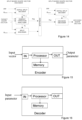
- Figure 14 is a schematic block diagram of a split algorithm encoder and decoder according to embodiments of the herein suggested solution.
- the encoder comprises an initial split decider unit, an energy variation analyzer unit, and a split encoder unit.
- the decoder comprises an initial split decider, and a decision decoder.
- the encoder and the decoder with its included units could be implemented in hardware and/or software.
- the encoder and decoder described herein could alternatively be implemented e.g. by one or more of a processor and adequate software with suitable storage or memory therefore, in order to perform the determining of an adequate number of splits and/or segments of an input vector, according to the embodiments described herein, see figures 15 and 16 .
- the incoming vector is received by an input (IN), to which the processor and the memory are connected, and the encoded representation of the vector, e.g. an audio signal (parameters), obtained from the software is outputted from the output (OUT).
- the decoder described herein could be implemented e.g. by one or more of a processor and adequate software with suitable storage or memory therefore, in order to perform the decoding of the input parameters, according to the embodiments described herein, see figure 16 .
- the incoming parameters are received by an input (IN), to which the processor and the memory are connected, and the decoded signal obtained from the software is outputted from the output (OUT).
- the technology described above may be comprised e.g. in a wireless device such as e.g. a user equipment, a mobile terminal, a tablet, a mobile wireless device for machine-to-machine communication, an integrated or embedded wireless card, an externally plugged in wireless card, a dongle, etc, or in a stationary or semi stationary device, such as a personal computer or a smart TV.
- a wireless device such as e.g. a user equipment, a mobile terminal, a tablet, a mobile wireless device for machine-to-machine communication, an integrated or embedded wireless card, an externally plugged in wireless card, a dongle, etc, or in a stationary or semi stationary device, such as a personal computer or a smart TV.
- Particular examples include one or more suitably configured digital signal processors and other known electronic circuits, e.g. discrete logic gates interconnected to perform a specialized function, or Application Specific Integrated Circuits (ASICs).
- digital signal processors and other known electronic circuits, e.g. discrete logic gates interconnected to perform a specialized function, or Application Specific Integrated Circuits (ASICs).
- ASICs Application Specific Integrated Circuits
- At least some of the steps, functions, procedures, modules, units and/or blocks described above may be implemented in software such as a computer program for execution by suitable processing circuitry including one or more processing units.
- the software could be carried by a carrier, such as an electronic signal, an optical signal, a radio signal, or a computer readable storage medium before and/or during the use of the computer program in the network nodes.
- the flow diagram or diagrams presented herein may be regarded as a computer flow diagram or diagrams, when performed by one or more processors.
- a corresponding apparatus may be defined as a group of function modules, where each step performed by the processor corresponds to a function module.
- the function modules are implemented as a computer program running on the processor.
- processing circuitry includes, but is not limited to, one or more microprocessors, one or more Digital Signal Processors, DSPs, one or more Central Processing Units, CPUs, and/or any suitable programmable logic circuitry such as one or more Field Programmable Gate Arrays, FPGAs, or one or more Programmable Logic Controllers, PLCs. That is, the units or modules in the arrangements in the different nodes described above could be implemented by a combination of analog and digital circuits, and/or one or more processors configured with software and/or firmware, e.g. stored in a memory.
- processors may be included in a single application-specific integrated circuitry, ASIC, or several processors and various digital hardware may be distributed among several separate components, whether individually packaged or assembled into a system-on-a-chip, SoC.
- ASIC application-specific integrated circuitry
- SoC system-on-a-chip
Landscapes
- Engineering & Computer Science (AREA)
- Physics & Mathematics (AREA)
- Multimedia (AREA)
- Signal Processing (AREA)
- Health & Medical Sciences (AREA)
- Human Computer Interaction (AREA)
- Audiology, Speech & Language Pathology (AREA)
- Acoustics & Sound (AREA)
- Computational Linguistics (AREA)
- Spectroscopy & Molecular Physics (AREA)
- Theoretical Computer Science (AREA)
- Compression, Expansion, Code Conversion, And Decoders (AREA)
- Compression Or Coding Systems Of Tv Signals (AREA)
- Error Detection And Correction (AREA)
Priority Applications (1)
| Application Number | Priority Date | Filing Date | Title |
|---|---|---|---|
| EP25168912.1A EP4593009A3 (en) | 2013-11-12 | 2014-11-11 | Split gain shape vector coding |
Applications Claiming Priority (4)
| Application Number | Priority Date | Filing Date | Title |
|---|---|---|---|
| US201361903024P | 2013-11-12 | 2013-11-12 | |
| EP14805698.9A EP3069449B1 (en) | 2013-11-12 | 2014-11-11 | Split gain shape vector coding |
| EP19186188.9A EP3624347B1 (en) | 2013-11-12 | 2014-11-11 | Split gain shape vector coding |
| PCT/SE2014/051339 WO2015072914A1 (en) | 2013-11-12 | 2014-11-11 | Split gain shape vector coding |
Related Parent Applications (2)
| Application Number | Title | Priority Date | Filing Date |
|---|---|---|---|
| EP14805698.9A Division EP3069449B1 (en) | 2013-11-12 | 2014-11-11 | Split gain shape vector coding |
| EP19186188.9A Division EP3624347B1 (en) | 2013-11-12 | 2014-11-11 | Split gain shape vector coding |
Related Child Applications (1)
| Application Number | Title | Priority Date | Filing Date |
|---|---|---|---|
| EP25168912.1A Division EP4593009A3 (en) | 2013-11-12 | 2014-11-11 | Split gain shape vector coding |
Publications (3)
| Publication Number | Publication Date |
|---|---|
| EP3913808A1 EP3913808A1 (en) | 2021-11-24 |
| EP3913808B1 true EP3913808B1 (en) | 2025-04-09 |
| EP3913808C0 EP3913808C0 (en) | 2025-04-09 |
Family
ID=52001045
Family Applications (4)
| Application Number | Title | Priority Date | Filing Date |
|---|---|---|---|
| EP21185475.7A Active EP3913808B1 (en) | 2013-11-12 | 2014-11-11 | Split gain shape vector coding |
| EP14805698.9A Active EP3069449B1 (en) | 2013-11-12 | 2014-11-11 | Split gain shape vector coding |
| EP19186188.9A Active EP3624347B1 (en) | 2013-11-12 | 2014-11-11 | Split gain shape vector coding |
| EP25168912.1A Pending EP4593009A3 (en) | 2013-11-12 | 2014-11-11 | Split gain shape vector coding |
Family Applications After (3)
| Application Number | Title | Priority Date | Filing Date |
|---|---|---|---|
| EP14805698.9A Active EP3069449B1 (en) | 2013-11-12 | 2014-11-11 | Split gain shape vector coding |
| EP19186188.9A Active EP3624347B1 (en) | 2013-11-12 | 2014-11-11 | Split gain shape vector coding |
| EP25168912.1A Pending EP4593009A3 (en) | 2013-11-12 | 2014-11-11 | Split gain shape vector coding |
Country Status (12)
| Country | Link |
|---|---|
| US (3) | US9385750B2 (enExample) |
| EP (4) | EP3913808B1 (enExample) |
| CN (3) | CN110649925B (enExample) |
| AR (2) | AR099351A1 (enExample) |
| BR (1) | BR112016009785B1 (enExample) |
| DK (2) | DK3624347T3 (enExample) |
| ES (3) | ES2773958T3 (enExample) |
| MX (3) | MX352106B (enExample) |
| PL (1) | PL3069449T3 (enExample) |
| PT (2) | PT3624347T (enExample) |
| TW (3) | TWI669943B (enExample) |
| WO (1) | WO2015072914A1 (enExample) |
Families Citing this family (6)
| Publication number | Priority date | Publication date | Assignee | Title |
|---|---|---|---|---|
| IN2014DN07726A (enExample) * | 2012-03-29 | 2015-05-15 | Ericsson Telefon Ab L M | |
| MX352106B (es) * | 2013-11-12 | 2017-11-09 | Ericsson Telefon Ab L M | Codificación de vector de ganancia y forma dividida. |
| MY203900A (en) | 2014-07-28 | 2024-07-23 | Ericsson Telefon Ab L M | Pyramid vector quantizer shape search |
| US10559315B2 (en) | 2018-03-28 | 2020-02-11 | Qualcomm Incorporated | Extended-range coarse-fine quantization for audio coding |
| US10762910B2 (en) | 2018-06-01 | 2020-09-01 | Qualcomm Incorporated | Hierarchical fine quantization for audio coding |
| CN111061907B (zh) * | 2019-12-10 | 2023-06-20 | 腾讯科技(深圳)有限公司 | 媒体数据处理方法、装置及存储介质 |
Family Cites Families (11)
| Publication number | Priority date | Publication date | Assignee | Title |
|---|---|---|---|---|
| US7310598B1 (en) * | 2002-04-12 | 2007-12-18 | University Of Central Florida Research Foundation, Inc. | Energy based split vector quantizer employing signal representation in multiple transform domains |
| US7343291B2 (en) * | 2003-07-18 | 2008-03-11 | Microsoft Corporation | Multi-pass variable bitrate media encoding |
| CN1327408C (zh) * | 2004-12-31 | 2007-07-18 | 苏州大学 | 一种低比特率语音编码器 |
| KR101768207B1 (ko) * | 2010-01-19 | 2017-08-16 | 삼성전자주식회사 | 축소된 예측 움직임 벡터의 후보들에 기초해 움직임 벡터를 부호화, 복호화하는 방법 및 장치 |
| US20120029926A1 (en) * | 2010-07-30 | 2012-02-02 | Qualcomm Incorporated | Systems, methods, apparatus, and computer-readable media for dependent-mode coding of audio signals |
| WO2012122299A1 (en) * | 2011-03-07 | 2012-09-13 | Xiph. Org. | Bit allocation and partitioning in gain-shape vector quantization for audio coding |
| EP2697795B1 (en) * | 2011-04-15 | 2015-06-17 | Telefonaktiebolaget L M Ericsson (PUBL) | Adaptive gain-shape rate sharing |
| KR20130047643A (ko) * | 2011-10-28 | 2013-05-08 | 한국전자통신연구원 | 통신 시스템에서 신호 코덱 장치 및 방법 |
| US9860604B2 (en) * | 2011-11-23 | 2018-01-02 | Oath Inc. | Systems and methods for internet video delivery |
| JP2013131918A (ja) * | 2011-12-21 | 2013-07-04 | Jvc Kenwood Corp | 動画像復号装置、動画像復号方法及び動画像復号プログラム |
| MX352106B (es) * | 2013-11-12 | 2017-11-09 | Ericsson Telefon Ab L M | Codificación de vector de ganancia y forma dividida. |
-
2014
- 2014-11-11 MX MX2016005806A patent/MX352106B/es active IP Right Grant
- 2014-11-11 DK DK19186188.9T patent/DK3624347T3/da active
- 2014-11-11 ES ES14805698T patent/ES2773958T3/es active Active
- 2014-11-11 WO PCT/SE2014/051339 patent/WO2015072914A1/en not_active Ceased
- 2014-11-11 EP EP21185475.7A patent/EP3913808B1/en active Active
- 2014-11-11 EP EP14805698.9A patent/EP3069449B1/en active Active
- 2014-11-11 CN CN201911003152.6A patent/CN110649925B/zh active Active
- 2014-11-11 US US14/440,713 patent/US9385750B2/en active Active
- 2014-11-11 ES ES19186188T patent/ES2891050T3/es active Active
- 2014-11-11 CN CN201480061092.2A patent/CN105706369B/zh active Active
- 2014-11-11 PL PL14805698T patent/PL3069449T3/pl unknown
- 2014-11-11 EP EP19186188.9A patent/EP3624347B1/en active Active
- 2014-11-11 PT PT191861889T patent/PT3624347T/pt unknown
- 2014-11-11 BR BR112016009785-8A patent/BR112016009785B1/pt active IP Right Grant
- 2014-11-11 PT PT148056989T patent/PT3069449T/pt unknown
- 2014-11-11 EP EP25168912.1A patent/EP4593009A3/en active Pending
- 2014-11-11 MX MX2019006311A patent/MX394518B/es unknown
- 2014-11-11 MX MX2017013371A patent/MX365684B/es unknown
- 2014-11-11 CN CN201911003154.5A patent/CN110708075B/zh active Active
- 2014-11-11 DK DK14805698.9T patent/DK3069449T3/da active
- 2014-11-11 ES ES21185475T patent/ES3019932T3/es active Active
- 2014-11-12 TW TW103139294A patent/TWI669943B/zh active
- 2014-11-12 TW TW109142236A patent/TWI776298B/zh active
- 2014-11-12 AR ARP140104266A patent/AR099351A1/es active IP Right Grant
- 2014-11-12 TW TW108125153A patent/TWI708501B/zh active
-
2016
- 2016-06-22 US US15/189,627 patent/US9602128B2/en active Active
-
2017
- 2017-02-07 US US15/426,483 patent/US9853659B2/en active Active
-
2018
- 2018-02-01 AR ARP180100239A patent/AR111014A2/es active IP Right Grant
Also Published As
Similar Documents
| Publication | Publication Date | Title |
|---|---|---|
| US9853659B2 (en) | Split gain shape vector coding | |
| EP3917016B1 (en) | Method and apparatus for pyramid vector quantization indexing | |
| US10147435B2 (en) | Audio coding method and apparatus | |
| RU2765985C2 (ru) | Классификация и кодирование аудиосигналов | |
| JP6494741B2 (ja) | 符号化及び復号化のための符号化装置、復号化装置、システム及び方法 | |
| CN102157151B (zh) | 一种多声道信号编码方法、解码方法、装置和系统 | |
| US10869029B2 (en) | Hybrid digital-analog coding | |
| WO2015000373A1 (zh) | 信号编码和解码方法以及设备 | |
| CN102098057B (zh) | 一种量化编解码方法和装置 |
Legal Events
| Date | Code | Title | Description |
|---|---|---|---|
| PUAI | Public reference made under article 153(3) epc to a published international application that has entered the european phase |
Free format text: ORIGINAL CODE: 0009012 |
|
| STAA | Information on the status of an ep patent application or granted ep patent |
Free format text: STATUS: THE APPLICATION HAS BEEN PUBLISHED |
|
| AC | Divisional application: reference to earlier application |
Ref document number: 3069449 Country of ref document: EP Kind code of ref document: P Ref document number: 3624347 Country of ref document: EP Kind code of ref document: P |
|
| AK | Designated contracting states |
Kind code of ref document: A1 Designated state(s): AL AT BE BG CH CY CZ DE DK EE ES FI FR GB GR HR HU IE IS IT LI LT LU LV MC MK MT NL NO PL PT RO RS SE SI SK SM TR |
|
| B565 | Issuance of search results under rule 164(2) epc |
Effective date: 20211001 |
|
| STAA | Information on the status of an ep patent application or granted ep patent |
Free format text: STATUS: REQUEST FOR EXAMINATION WAS MADE |
|
| 17P | Request for examination filed |
Effective date: 20220524 |
|
| RBV | Designated contracting states (corrected) |
Designated state(s): AL AT BE BG CH CY CZ DE DK EE ES FI FR GB GR HR HU IE IS IT LI LT LU LV MC MK MT NL NO PL PT RO RS SE SI SK SM TR |
|
| STAA | Information on the status of an ep patent application or granted ep patent |
Free format text: STATUS: EXAMINATION IS IN PROGRESS |
|
| 17Q | First examination report despatched |
Effective date: 20230908 |
|
| GRAP | Despatch of communication of intention to grant a patent |
Free format text: ORIGINAL CODE: EPIDOSNIGR1 |
|
| STAA | Information on the status of an ep patent application or granted ep patent |
Free format text: STATUS: GRANT OF PATENT IS INTENDED |
|
| INTG | Intention to grant announced |
Effective date: 20241106 |
|
| GRAS | Grant fee paid |
Free format text: ORIGINAL CODE: EPIDOSNIGR3 |
|
| GRAA | (expected) grant |
Free format text: ORIGINAL CODE: 0009210 |
|
| STAA | Information on the status of an ep patent application or granted ep patent |
Free format text: STATUS: THE PATENT HAS BEEN GRANTED |
|
| AC | Divisional application: reference to earlier application |
Ref document number: 3069449 Country of ref document: EP Kind code of ref document: P Ref document number: 3624347 Country of ref document: EP Kind code of ref document: P |
|
| AK | Designated contracting states |
Kind code of ref document: B1 Designated state(s): AL AT BE BG CH CY CZ DE DK EE ES FI FR GB GR HR HU IE IS IT LI LT LU LV MC MK MT NL NO PL PT RO RS SE SI SK SM TR |
|
| REG | Reference to a national code |
Ref country code: GB Ref legal event code: FG4D |
|
| REG | Reference to a national code |
Ref country code: CH Ref legal event code: EP |
|
| REG | Reference to a national code |
Ref country code: DE Ref legal event code: R096 Ref document number: 602014091796 Country of ref document: DE |
|
| REG | Reference to a national code |
Ref country code: IE Ref legal event code: FG4D |
|
| U01 | Request for unitary effect filed |
Effective date: 20250409 |
|
| REG | Reference to a national code |
Ref country code: ES Ref legal event code: FG2A Ref document number: 3019932 Country of ref document: ES Kind code of ref document: T3 Effective date: 20250521 |
|
| U07 | Unitary effect registered |
Designated state(s): AT BE BG DE DK EE FI FR IT LT LU LV MT NL PT RO SE SI Effective date: 20250417 |
|
| PG25 | Lapsed in a contracting state [announced via postgrant information from national office to epo] |
Ref country code: NO Free format text: LAPSE BECAUSE OF FAILURE TO SUBMIT A TRANSLATION OF THE DESCRIPTION OR TO PAY THE FEE WITHIN THE PRESCRIBED TIME-LIMIT Effective date: 20250709 Ref country code: GR Free format text: LAPSE BECAUSE OF FAILURE TO SUBMIT A TRANSLATION OF THE DESCRIPTION OR TO PAY THE FEE WITHIN THE PRESCRIBED TIME-LIMIT Effective date: 20250710 |
|
| PG25 | Lapsed in a contracting state [announced via postgrant information from national office to epo] |
Ref country code: PL Free format text: LAPSE BECAUSE OF FAILURE TO SUBMIT A TRANSLATION OF THE DESCRIPTION OR TO PAY THE FEE WITHIN THE PRESCRIBED TIME-LIMIT Effective date: 20250409 |
|
| PG25 | Lapsed in a contracting state [announced via postgrant information from national office to epo] |
Ref country code: HR Free format text: LAPSE BECAUSE OF FAILURE TO SUBMIT A TRANSLATION OF THE DESCRIPTION OR TO PAY THE FEE WITHIN THE PRESCRIBED TIME-LIMIT Effective date: 20250409 |
|
| PG25 | Lapsed in a contracting state [announced via postgrant information from national office to epo] |
Ref country code: RS Free format text: LAPSE BECAUSE OF FAILURE TO SUBMIT A TRANSLATION OF THE DESCRIPTION OR TO PAY THE FEE WITHIN THE PRESCRIBED TIME-LIMIT Effective date: 20250709 |
|
| PG25 | Lapsed in a contracting state [announced via postgrant information from national office to epo] |
Ref country code: IS Free format text: LAPSE BECAUSE OF FAILURE TO SUBMIT A TRANSLATION OF THE DESCRIPTION OR TO PAY THE FEE WITHIN THE PRESCRIBED TIME-LIMIT Effective date: 20250809 |