EP3069449B1 - Split gain shape vector coding - Google Patents
Split gain shape vector coding Download PDFInfo
- Publication number
- EP3069449B1 EP3069449B1 EP14805698.9A EP14805698A EP3069449B1 EP 3069449 B1 EP3069449 B1 EP 3069449B1 EP 14805698 A EP14805698 A EP 14805698A EP 3069449 B1 EP3069449 B1 EP 3069449B1
- Authority
- EP
- European Patent Office
- Prior art keywords
- vector
- segments
- segment
- target vector
- avg
- Prior art date
- Legal status (The legal status is an assumption and is not a legal conclusion. Google has not performed a legal analysis and makes no representation as to the accuracy of the status listed.)
- Active
Links
- 239000013598 vector Substances 0.000 title claims description 133
- 238000000034 method Methods 0.000 claims description 44
- 238000013139 quantization Methods 0.000 claims description 18
- 238000004590 computer program Methods 0.000 claims description 8
- 230000005236 sound signal Effects 0.000 claims description 4
- 230000003287 optical effect Effects 0.000 claims description 2
- 238000012545 processing Methods 0.000 description 28
- 230000006870 function Effects 0.000 description 9
- 238000010586 diagram Methods 0.000 description 8
- 230000008901 benefit Effects 0.000 description 7
- 238000005516 engineering process Methods 0.000 description 6
- 238000004891 communication Methods 0.000 description 5
- 238000004458 analytical method Methods 0.000 description 4
- 230000008859 change Effects 0.000 description 4
- 230000009471 action Effects 0.000 description 3
- 230000009286 beneficial effect Effects 0.000 description 3
- 230000011664 signaling Effects 0.000 description 3
- 230000001143 conditioned effect Effects 0.000 description 2
- 230000007423 decrease Effects 0.000 description 2
- 230000014509 gene expression Effects 0.000 description 2
- 238000005192 partition Methods 0.000 description 2
- 238000004088 simulation Methods 0.000 description 2
- 238000012360 testing method Methods 0.000 description 2
- 230000006978 adaptation Effects 0.000 description 1
- 238000003491 array Methods 0.000 description 1
- 238000007796 conventional method Methods 0.000 description 1
- 238000011161 development Methods 0.000 description 1
- 230000018109 developmental process Effects 0.000 description 1
- 235000019800 disodium phosphate Nutrition 0.000 description 1
- 230000008450 motivation Effects 0.000 description 1
- 230000009467 reduction Effects 0.000 description 1
- 230000008672 reprogramming Effects 0.000 description 1
- 230000003595 spectral effect Effects 0.000 description 1
- 238000001228 spectrum Methods 0.000 description 1
- 230000001360 synchronised effect Effects 0.000 description 1
- 239000002699 waste material Substances 0.000 description 1
Images


Classifications
-
- H—ELECTRICITY
- H03—ELECTRONIC CIRCUITRY
- H03M—CODING; DECODING; CODE CONVERSION IN GENERAL
- H03M7/00—Conversion of a code where information is represented by a given sequence or number of digits to a code where the same, similar or subset of information is represented by a different sequence or number of digits
- H03M7/30—Compression; Expansion; Suppression of unnecessary data, e.g. redundancy reduction
- H03M7/3082—Vector coding
-
- G—PHYSICS
- G10—MUSICAL INSTRUMENTS; ACOUSTICS
- G10L—SPEECH ANALYSIS OR SYNTHESIS; SPEECH RECOGNITION; SPEECH OR VOICE PROCESSING; SPEECH OR AUDIO CODING OR DECODING
- G10L19/00—Speech or audio signals analysis-synthesis techniques for redundancy reduction, e.g. in vocoders; Coding or decoding of speech or audio signals, using source filter models or psychoacoustic analysis
- G10L19/002—Dynamic bit allocation
-
- G—PHYSICS
- G10—MUSICAL INSTRUMENTS; ACOUSTICS
- G10L—SPEECH ANALYSIS OR SYNTHESIS; SPEECH RECOGNITION; SPEECH OR VOICE PROCESSING; SPEECH OR AUDIO CODING OR DECODING
- G10L19/00—Speech or audio signals analysis-synthesis techniques for redundancy reduction, e.g. in vocoders; Coding or decoding of speech or audio signals, using source filter models or psychoacoustic analysis
- G10L19/02—Speech or audio signals analysis-synthesis techniques for redundancy reduction, e.g. in vocoders; Coding or decoding of speech or audio signals, using source filter models or psychoacoustic analysis using spectral analysis, e.g. transform vocoders or subband vocoders
- G10L19/032—Quantisation or dequantisation of spectral components
- G10L19/038—Vector quantisation, e.g. TwinVQ audio
-
- G—PHYSICS
- G10—MUSICAL INSTRUMENTS; ACOUSTICS
- G10L—SPEECH ANALYSIS OR SYNTHESIS; SPEECH RECOGNITION; SPEECH OR VOICE PROCESSING; SPEECH OR AUDIO CODING OR DECODING
- G10L19/00—Speech or audio signals analysis-synthesis techniques for redundancy reduction, e.g. in vocoders; Coding or decoding of speech or audio signals, using source filter models or psychoacoustic analysis
- G10L19/04—Speech or audio signals analysis-synthesis techniques for redundancy reduction, e.g. in vocoders; Coding or decoding of speech or audio signals, using source filter models or psychoacoustic analysis using predictive techniques
- G10L19/16—Vocoder architecture
- G10L19/18—Vocoders using multiple modes
- G10L19/22—Mode decision, i.e. based on audio signal content versus external parameters
-
- H—ELECTRICITY
- H04—ELECTRIC COMMUNICATION TECHNIQUE
- H04N—PICTORIAL COMMUNICATION, e.g. TELEVISION
- H04N19/00—Methods or arrangements for coding, decoding, compressing or decompressing digital video signals
- H04N19/10—Methods or arrangements for coding, decoding, compressing or decompressing digital video signals using adaptive coding
- H04N19/102—Methods or arrangements for coding, decoding, compressing or decompressing digital video signals using adaptive coding characterised by the element, parameter or selection affected or controlled by the adaptive coding
- H04N19/124—Quantisation
-
- G—PHYSICS
- G10—MUSICAL INSTRUMENTS; ACOUSTICS
- G10L—SPEECH ANALYSIS OR SYNTHESIS; SPEECH RECOGNITION; SPEECH OR VOICE PROCESSING; SPEECH OR AUDIO CODING OR DECODING
- G10L15/00—Speech recognition
- G10L15/08—Speech classification or search
-
- H—ELECTRICITY
- H03—ELECTRONIC CIRCUITRY
- H03M—CODING; DECODING; CODE CONVERSION IN GENERAL
- H03M7/00—Conversion of a code where information is represented by a given sequence or number of digits to a code where the same, similar or subset of information is represented by a different sequence or number of digits
- H03M7/30—Compression; Expansion; Suppression of unnecessary data, e.g. redundancy reduction
-
- H—ELECTRICITY
- H04—ELECTRIC COMMUNICATION TECHNIQUE
- H04B—TRANSMISSION
- H04B1/00—Details of transmission systems, not covered by a single one of groups H04B3/00 - H04B13/00; Details of transmission systems not characterised by the medium used for transmission
- H04B1/66—Details of transmission systems, not covered by a single one of groups H04B3/00 - H04B13/00; Details of transmission systems not characterised by the medium used for transmission for reducing bandwidth of signals; for improving efficiency of transmission
- H04B1/665—Details of transmission systems, not covered by a single one of groups H04B3/00 - H04B13/00; Details of transmission systems not characterised by the medium used for transmission for reducing bandwidth of signals; for improving efficiency of transmission using psychoacoustic properties of the ear, e.g. masking effect
-
- H—ELECTRICITY
- H04—ELECTRIC COMMUNICATION TECHNIQUE
- H04N—PICTORIAL COMMUNICATION, e.g. TELEVISION
- H04N19/00—Methods or arrangements for coding, decoding, compressing or decompressing digital video signals
- H04N19/60—Methods or arrangements for coding, decoding, compressing or decompressing digital video signals using transform coding
- H04N19/61—Methods or arrangements for coding, decoding, compressing or decompressing digital video signals using transform coding in combination with predictive coding
Definitions
- the invention disclosed herein generally relates to gain shape vector encoding and decoding, and in particular to split gain shape vector quantization.
- Encoding methods for e.g. audio and/or video typically comprise some type of quantization of signal segments. It is known that unconstrained vector quantization (VQ) is a useful quantization method for grouped samples, i.e. vectors, of a certain length.
- VQ unconstrained vector quantization
- the memory and search complexity constraints have led to the development of structured vector quantizers. Different structures give different trade-offs in terms of search complexity and memory requirements.
- gain-shape vector quantization is to quantize a pair of gain and shape components ⁇ r, G ⁇ instead of directly quantizing the target vector.
- the gain and shape components are then encoded using a shape quantizer which is tuned for the normalized shape input, and a gain quantizer which handles the dynamics of the signal.
- This structure is commonly used in audio coding since the division into dynamics and shape, also denoted fine structure, fits well with the perceptual auditory model.
- audio codecs such as IETF Opus and ITU-T G.719 uses a gain-shape vector quantization to encode the spectral coefficients of the target audio signal. Both these codecs use a fixed band structure to partition the spectrum into multiple segments, and there is no adaptation of the band structure to any changes in the target vector.
- gain shape quantization is to find a suitable vector length. Longer vectors give larger variations within the vector such that the shape quantizer needs to handle the dynamics of the signal. Shorter vectors reduce the dynamics within the vector, but may suffer from the fact the lower dimensionality of the shape VQ has less capability to exploit the sample correlation. In addition, the overhead for gain coding increases as the number of partitions increases, which leaves fewer bits for the for the shape coding.
- a method for gain shape vector quantization according to claim 1 is disclosed.
- an audio encoder operable to perform gain shape vector quantization according to claim 6 is disclosed.
- a computer program comprises instructions which when run on an apparatus causes the apparatus to perform the method according to the first aspect described above.
- a concept of embodiments described herein is to analyze the shape and determine a suitable resolution into sub-vectors, given a target vector of a certain size. This may reduce the quantization error, and increase perceived quality, in case of audio codec. Further, it is an aim of some embodiments described herein to find an optimal number of sections, i.e. number of splits of the target vector.
- Embodiments herein relate to a method for supporting split gain shape vector encoding.
- the method is intended to be performed by a media encoder in situations where the encoding of each vector segment is subjected to a constraint related to a maximum number of bits, B MAX . That is, in situations where the maximum number of bits allowed for encoding of a vector segment is B MAX .
- This constraint may be due to e.g. processing capacity and/or memory capacity of the media encoder.
- a method according to an exemplifying embodiment will be described below with reference to figure 1 .
- the method illustrated in figure 1 comprises, for a target vector x, determining 101 an initial number, Np _init , of segments for the target vector x.
- the number Np _init could be determined based on e.g. B MAX and a bit budget, i.e. the number of bits allocated for encoding the entire vector x.
- the method further comprises determining 102 an average number of bits per segment, B AVG , based on the vector bit budget and Np _init . Note that the vector x need not actually be split on this stage, even though an initial number of segments and an average number of bits available for an initial vector segment have been determined.
- the method further comprises determining 103 a final number, Np, of segments to be used in the gain shape vector encoding, based on energies of the Np _init segments and a difference between B MAX and B AVG .
- determining a final number of segments By determining a final number of segments based on these paramters, an efficient allocation of the bits of the bit budget over the target vector is enabled, which will be described more in detail further below.
- the determining of a number of segments could alternatively be expressed as determining a number of splits, since the number of segments and the number of splits are closely related.
- the term split could be used to denote a segment.
- the determined final number, Np, of segments may then be indicated to a media decoder, in order to enable the media decoder to adequately decode the encoded gain shape vector. It should be noted that it is not necessarily the actual number of segments that is indicated, but rather a change as compared to the determined initial number of segments. Regarding the determining of Np _init , this initial number of segments may be given for the encoder and decoder. In such cases the term "determining" would refer e.g. to establishing Np _init for use, or similar.
- the determining of a final number of segments comprises increasing 204 the number of segments (and splits) when a relation between the energies of the Np _init segments and the difference between B MAX and B AVG fulfills a criterion.
- increasing the number of segments is here meant increasing, as compared to the initial number Np _init , of segments.
- the increase of the number of segments could then be indicated 205 to a media decoder in a suitable manner. It is advantageous to use as few bits as possible for indicating the final number of segments to a decoder.
- the final increased number of segments could be indicated to the media decoder using a single bit, which is often referred to as a flag.
- the bit could be set to "1", or “true”, when an increased number of segments is applied, and be set to "0", or "false", when the initial number of segments is to be used. That is, the determining of a final number of segments may further comprise to determine 206 that the initial number, Np _init , of segments, should be used, i.e.
- Np Np _init when the relation between the energies of the Np _init segments and the difference between B MAX and B AVG does not fulfill the criterion, or, when a corresponding criterion is not met. This is illustrated as the action 206 in figure 2 .
- the determining of a final number, Np, of segments may comprise increasing 204 the number of segments, as compared to the initial number, for the target vector x, when a maximum deviation, of a target vector segment energy, from an average per-segment energy value, E AVG , for the target vector x is larger than a threshold based on the difference between B MAX and B AVG . That is, an energy variation over the target vector segments may be compared to a threshold based on the difference between B MAX and B AVG .
- E AVG The logic behind using a maximum deviation from an average per-segment energy value, E AVG is, described in a simplified manner, that when there are large deviations from an average per-segment energy, there are large differences in the perceptual importance of the different segments. It should be noted that the "threshold" comparison could be expressed the other way around, such that the difference between B MAX and B AVG is compared to a threshold, which depends on, or is based on the energies of the Np_init segments.
- the above could be expressed as that when the difference between B MAX and B AVG is smaller than a threshold depending on a maximum deviation, of a target vector segment energy, from an average per-segment energy value, E AVG , for the target vector x, the number of segments should be increased, etc.
- this could be expressed as that the number of splits should be increased when M > ⁇ ( B MAX - B AVG ), or, when B MAX ⁇ B AVG ⁇ M ⁇ ; where either ⁇ ( B MAX - B AVG ) or M ⁇ may be denoted threshold.
- the determining, or decision, of when to add an additional split may be based on testing whether the energy variation measure M is above a certain threshold based on B MAX and B AVG as:
- Figure 3a illustrates a mean energy per segment (black dots) and total average energy E AVG (average of the segment averages). To minimize the coding distortion, it is desired to use more bits for encoding segments comprising more energy than for encoding segments comprising less energy. Thus, when there is large variation in energy between segments, it would be desired to reallocate bits from segments comprising less energy to segments comprising more energy, assuming that all segments initially are allocated at least approximately B AVG bits, i.e. assuming an initial even distribution of the bits over the segments.
- Figure 3b is a simple graph illustrating a number of segments, a B MAX value and a B AVG value.
- B MAX and B AVG which could also be denoted the headroom herein, are "small", e.g. smaller than a threshold, it will not be possible to reallocate that many bits to the high energy content segments, before reaching B MAX .
- B AVG will be reduced, which is illustrated by a dashed arrow in figure 3a , and thus increase the possibility to allocate more bits to high energy content segments.
- a higher positive deviation, in number of bits is allowed from B AVG , which enables reallocation of bits.
- the maximum allowed positive deviation is B MAX - B AVG .
- reallocation does not imply that an average number B AVG of bits is actually allocated to each segment before reallocating, but is only used to facilitate understanding of the solution provided herein.
- An exemplifying embodiment could be described as: when an energy variation between the vector segments is "large” in relation to a headroom, B MAX - B AVG , the number of splits and segments is increased by "1", which is then indicated to a decoder by the setting of a one-bit flag.
- the determining of "large” may be performed by use of a threshold value, which may be selected based on e.g. simulations.
- a threshold value which may be selected based on e.g. simulations.
- FIG 4 the energy variation is denoted M, and in this example, the threshold M THR is based on B MAX - B AVG .
- Different examples of expressions for an energy variation will be described further below.
- a tuning parameter ⁇ may be used to make the decision threshold proportional to the headroom.
- a value of ⁇ may be derived e.g. based on simulations.
- the performing of the analysis, and the indicating of a result may be conditioned, i.e. only be performed when at least one additional condition is met.
- One such additional condition may be that the vector bit budget is above a threshold. The reason for such a condition would be that when the bit budget is low, there are not that many bits to reallocate to other segments.
- Another additional condition could be that the initial number of splits or sections should be below a threshold. The reason for such a condition would be e.g. complexity constraints.
- the embodiments described above are intended to be non-recursive, which implies a low complexity. This may be advantageous, as compared to more resource-demanding recursive methods. It should further be note that the segments are intended to be at least approximately evenly distributed over the vector, i.e. be of, at least approximately, equal size. This may also be an advantage, as compared to methods generating segments of very different sizes.
- Embodiments herein further relate to a method for supporting split gain shape vector decoding.
- the method corresponds to the encoding method described above.
- the method is intended to be performed by a media decoder in situations where a representation of each vector segment of a gain shape vector x is subjected to a constraint related to a maximum number of bits, B MAX , allowed for encoding a vector segment.
- B MAX maximum number of bits
- the method illustrated in figure 5 comprises determining 501 an initial number, Np_ init , of segments, for a vector to be reconstructed x q ;
- the method further comprises receiving 502 an indication, from a media encoder, of whether an increased number of segments is applied for the vector x q , or not, and determining 503 a final number of segments for the decoding of the vector x q based on the initial number of segments and the received indication.
- the vector x q may then be decoded 504 based on the final number of segments.
- the indication may, in analogy with the example on the encoder side, be received in form of a bit-flag, which is set to e.g.
- Np Np _init + 1
- Np Np_ init + 1
- Np Np_ init + 2
- the receiving of an indication may be conditioned, and thus only performed when one or more additional conditions are met.
- additional conditions may, as previously stated, be e.g. that the vector bit budget is above a threshold T1, and that the initial number of splits or segments is below a threshold T2, and/or that the bitrate per sample B SAMPLE is above a given limit. (T1 and T2 are just used to indicate that it is not the same threshold for the two cases).
- Energy variations across a target vector can be captured by splitting the target vector into smaller sections.
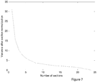
- the variance value decreases fast for the first few number of splits but then saturates, as illustrated in figure 7 .
- the saturation point can be interpreted as the point where further resolution in more sections is not needed. Further, it may be noted that this curve will always converge to zero since the final split will result in sections containing one sample each with variance zero.
- An example target vector with corresponding section energies for 3 and 4-way split is shown in figure 8 .
- the variance of the energies among the sections/segments is compared for different split configurations, i.e. for different numbers of segments.
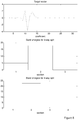
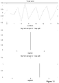
- Figure 10 illustrates an example target vector (upper figure) and the corresponding segment energies for 2 (middle figure) and 3-way (lower figure) split, respectively, of the example target vector.
- figure 11 the corresponding variance of the segment energies is shown for a varying number of segments. Considering the change from 2 segments to 3 segments, the variance V is increasing, which then indicates that a split into 3 segments would be beneficial over a split into 2 segments.
- the decision for additional split is made on basis of: where ⁇ is a lower threshold for the increase in variance of the segment energies between two consecutive number of splits.
- ⁇ is a lower threshold for the increase in variance of the segment energies between two consecutive number of splits.
- the increase in variance is sufficient, i.e. in this example exceeds the threshold ⁇ , the number of segments is increased, e.g. by one.
- the use of an additional split could be signalled from the encoder to the decoder by, for example, using one bit for signalling one additional split or no additional split. However, more bits could be used for signalling more than one additional split if preferred.
- a variation on the embodiment above is to directly use the average energy per coefficient E coeff in normalized segments as a measure of the energy variations.
- the motivation for doing this is that when the average energy per coefficient does not change much between two consecutive number of splits, the distribution within each segment is similar and does not benefit from further splitting, while a large change between two consecutive number of splits motivates an additional split.
- the decision can be made based on a threshold ⁇ similar to the above expression:
- the intent is to increase the number of splits in case the estimated energy deviation is large.
- the reason is that an additional split should provide slightly more freedom to allocate the bits locally, as previously described.
- the decision when to add an additional split may be based on testing whether the energy variation measure M is above a certain threshold M THR as (which is also illustrated in figure 4 ):
- the decision for additional split may also be affected by the constraints on the encoder for the different sections or segments.
- an additional split may be needed if the necessary bit allocation cannot be fit below the maximum number of bits for each section or segment, B MAX .
- the difference between the maximum number of bits per section B MAX and the average number of bits per section B AVG may be denoted the headroom for the bit allocation ( B MAX - B AVG ).
- the term "band” could here be interpreted e.g. as the frequency band, which the target vector represents.
- the decision threshold may be adjusted using a tuning parameter ⁇ to make the decision threshold proportional to the headroom:
- the decision to use an additional split may also be encoded as a parameter and sent from the encoder to the decoder.
- the above algorithm may be restricted to be used only is situations where it may be beneficial. For instance, it may be limited to be used only when the initial number of splits or segments Np _init is below a maximum number of splits or segments, e.g. N P_init ⁇ N P,m ⁇ x and/or when the bitrate per sample B SAMPLE is above a given limit, e.g. B SAMPLE >B SAMPLE,THR .
- the same condition should be used in the encoder and decoder for correct bitstream decoding.
- FIG. 12a An exemplifying embodiment of a media encoder is illustrated in a general manner in figure 12a .
- media encoder is referred to an encoder for e.g. audio and/or video signals.
- the encoder 1200 is configured to perform at least one of the method embodiments described above with reference to any of figures 1-2 and 4 .
- the encoder 1200 is associated with the same technical features, objects and advantages as the previously described method embodiments. The encoder will be described in brief in order to avoid unnecessary repetition.
- the encoder may be implemented and/or described as follows:
- the encoder 1200 is configured for split gain shape vector encoding.
- the encoder 1200 comprises processing circuitry, or processing means 1201 and a communication interface 1202.
- the processing circuitry 1201 is configured to cause the encoder 1200 to, for a target shape vector x: determine an initial number Np _init of segments, and further to determine an average number of bits per segment, B AVG , based on a vector bit budget and Np _init .
- the processing circuitry 1201 is further configured to cause the encoder to determine a final number of segments to be used in the gain shape vector encoding based on energies of the Np _init segments and a difference between B MAX and B AVG .
- the communication interface 1202 which may also be denoted e.g. Input/Output (I/O) interface, includes an interface for sending data to and receiving data from other entities or modules.
- I/O Input/Output
- the processing circuitry 1201 could, as illustrated in figure 12b , comprise processing means, such as a processor 1203, e.g. a CPU, and a memory 1204 for storing or holding instructions.
- processing means such as a processor 1203, e.g. a CPU, and a memory 1204 for storing or holding instructions.
- the memory would then comprise instructions, e.g. in form of a computer program 1205, which when executed by the processing means 1203 causes the encoder 1200 to perform the actions described above.
- the processing circuitry 1201 comprises a first determining unit 1206, configured to cause the encoder 1200 to: determine an initial number Np _init of segments for a target shape vector x.
- the processing circuitry further comprises a second determining unit 1207 configured to cause the encoder to determine an average number of bits per segment, B AVG , based on a vector bit budget and Np _init .
- the processing circuitry further comprises a third determining unit 1208, configured to cause the encoder to determine a final number of segments, for the vector x, to be used in the gain shape vector encoding, based on energies of the Np_init segments and a difference between B MAX and B AVG .
- the processing circuitry 1201 could comprise more units, such as an indicating unit 1209 configured to cause the encoder to indicate the final number of segments, e.g. an increase by one segment as compared to the initial number, to a media decoder. This task could alternatively be performed by one of the other units.
- the encoders described above could be configured for the different method embodiments described herein, such as increasing the number of segments, as compared to the initial number, for the target vector x for the gain shape vector encoding when a maximum deviation, of a target vector segment energy, from an average per-segment energy value, E AVG , for the target vector x is larger than a threshold based on the difference between B MAX and B AVG .
- the encoder 1200 may be assumed to comprise further functionality, for carrying out regular encoder functions.
- Embodiments herein also relate to a media decoder 1300 configured for carrying out embodiments of the decoding method described above. That is, the method for supporting split gain shape vector decoding, illustrated e.g. in figure 5 .
- An exemplifying embodiment of a decoder 1300 is illustrated in a general manner in figure 13a .
- the decoder 1300 is configured to perform at least one of the method embodiments described above with reference to figures 5-6 .
- the decoder 1300 is associated with the same technical features, objects and advantages as the previously described method embodiments. The decoder will be described in brief in order to avoid unnecessary repetition.
- the decoder 1300 is configured for supporting split gain shape vector decoding, and is operable to perform split gain shape vector decoding.
- the decoder 1300 comprises processing circuitry 1301 and a communication interface 1302.
- the processing circuitry 1301 is configured to cause the network node to determine an initial number Np _init , for a vector x q to be reconstructed; and further to receive an indication, from a media encoder, of whether an increased number of segments is applied for the vector x q , or not.
- the processing circuitry 1301 is further configured to cause the network node to determine a final number of segments for the decoding of the vector x q based on the received indication.
- I/O Input/Output
- the processing circuitry 1301 could, as illustrated in figure 13b , comprise processing means, such as a processor 1303, and a memory 1304 for storing or holding instructions.
- the memory would then comprise instructions, e.g. in form of computer program 1305, which when executed by the processing means 1303 causes the network node 1300 to perform the actions described above.
- the processing circuitry 1301 here comprises a first determining unit 1306, configured to cause the network node to determine an initial number of segments, Np _init , for a vector x q to be reconstructed.
- the processing circuitry 1301 further comprises a receiving unit 1307, configured to cause the network node to receive an indication, from a media encoder, of whether an increased number of segments is applied for the vector x q , or not.
- the processing circuitry 1301 further comprises a second determining unit 1308, configured to cause the network node to determine a final number of segments for the decoding of the vector x q based on the received indication.
- the network node 1300 may be assumed to comprise further functionality, for carrying out regular decoder functions.
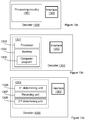
- Figure 14 is a schematic block diagram of a split algorithm encoder and decoder according to embodiments of the herein suggested solution.
- the encoder comprises an initial split decider unit, an energy variation analyzer unit, and a split encoder unit.
- the decoder comprises an initial split decider, and a decision decoder.
- the encoder and the decoder with its included units could be implemented in hardware and/or software.
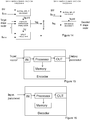
- the encoder and decoder described herein could alternatively be implemented e.g. by one or more of a processor and adequate software with suitable storage or memory therefore, in order to perform the determining of an adequate number of splits and/or segments of an input vector, according to the embodiments described herein, see figures 15 and 16 .
- the incoming vector is received by an input (IN), to which the processor and the memory are connected, and the encoded representation of the vector, e.g. an audio signal (parameters), obtained from the software is outputted from the output (OUT).
- the decoder described herein could be implemented e.g. by one or more of a processor and adequate software with suitable storage or memory therefore, in order to perform the decoding of the input parameters, according to the embodiments described herein, see figure 16 .
- the incoming parameters are received by an input (IN), to which the processor and the memory are connected, and the decoded signal obtained from the software is outputted from the output (OUT).
- the technology described above may be comprised e.g. in a wireless device such as e.g. a user equipment, a mobile terminal, a tablet, a mobile wireless device for machine-to-machine communication, an integrated or embedded wireless card, an externally plugged in wireless card, a dongle, etc, or in a stationary or semi stationary device, such as a personal computer or a smart TV.
- a wireless device such as e.g. a user equipment, a mobile terminal, a tablet, a mobile wireless device for machine-to-machine communication, an integrated or embedded wireless card, an externally plugged in wireless card, a dongle, etc, or in a stationary or semi stationary device, such as a personal computer or a smart TV.
- Particular examples include one or more suitably configured digital signal processors and other known electronic circuits, e.g. discrete logic gates interconnected to perform a specialized function, or Application Specific Integrated Circuits (ASICs).
- digital signal processors and other known electronic circuits, e.g. discrete logic gates interconnected to perform a specialized function, or Application Specific Integrated Circuits (ASICs).
- ASICs Application Specific Integrated Circuits
- At least some of the steps, functions, procedures, modules, units and/or blocks described above may be implemented in software such as a computer program for execution by suitable processing circuitry including one or more processing units.
- the software could be carried by a carrier, such as an electronic signal, an optical signal, a radio signal, or a computer readable storage medium before and/or during the use of the computer program in the network nodes.
- the flow diagram or diagrams presented herein may be regarded as a computer flow diagram or diagrams, when performed by one or more processors.
- a corresponding apparatus may be defined as a group of function modules, where each step performed by the processor corresponds to a function module.
- the function modules are implemented as a computer program running on the processor.
- processing circuitry includes, but is not limited to, one or more microprocessors, one or more Digital Signal Processors, DSPs, one or more Central Processing Units, CPUs, and/or any suitable programmable logic circuitry such as one or more Field Programmable Gate Arrays, FPGAs, or one or more Programmable Logic Controllers, PLCs. That is, the units or modules in the arrangements in the different nodes described above could be implemented by a combination of analog and digital circuits, and/or one or more processors configured with software and/or firmware, e.g. stored in a memory.
- processors may be included in a single application-specific integrated circuitry, ASIC, or several processors and various digital hardware may be distributed among several separate components, whether individually packaged or assembled into a system-on-a-chip, SoC.
- ASIC application-specific integrated circuitry
- SoC system-on-a-chip
Description
- The invention disclosed herein generally relates to gain shape vector encoding and decoding, and in particular to split gain shape vector quantization.
- Encoding methods for e.g. audio and/or video, typically comprise some type of quantization of signal segments. It is known that unconstrained vector quantization (VQ) is a useful quantization method for grouped samples, i.e. vectors, of a certain length. However, the memory and search complexity constraints have led to the development of structured vector quantizers. Different structures give different trade-offs in terms of search complexity and memory requirements. One such conventional method for structured vector quantization is the gain-shape vector quantization, where the target vector x is represented using a shape vector r and a gain G:

- The concept of gain-shape vector quantization is to quantize a pair of gain and shape components {r, G} instead of directly quantizing the target vector. The gain and shape components are then encoded using a shape quantizer which is tuned for the normalized shape input, and a gain quantizer which handles the dynamics of the signal. This structure is commonly used in audio coding since the division into dynamics and shape, also denoted fine structure, fits well with the perceptual auditory model.
- Further, many audio codecs such as IETF Opus and ITU-T G.719 uses a gain-shape vector quantization to encode the spectral coefficients of the target audio signal. Both these codecs use a fixed band structure to partition the spectrum into multiple segments, and there is no adaptation of the band structure to any changes in the target vector.
- One issue with gain shape quantization is to find a suitable vector length. Longer vectors give larger variations within the vector such that the shape quantizer needs to handle the dynamics of the signal. Shorter vectors reduce the dynamics within the vector, but may suffer from the fact the lower dimensionality of the shape VQ has less capability to exploit the sample correlation. In addition, the overhead for gain coding increases as the number of partitions increases, which leaves fewer bits for the for the shape coding.
- It is desired to achieve an efficient gain shape vector encoding and decoding.
- According to a first aspect, a method for gain shape vector quantization according to
claim 1 is disclosed. - According to a second aspect, an audio encoder operable to perform gain shape vector quantization according to
claim 6 is disclosed. - According to a third aspect, a computer program comprises instructions which when run on an apparatus causes the apparatus to perform the method according to the first aspect described above.
- The foregoing and other objects, features, and advantages of the technology disclosed herein will be apparent from the following more particular description of embodiments as illustrated in the accompanying drawings. The drawings are not necessarily to scale, emphasis instead being placed upon illustrating the principles of the technology disclosed herein.
-
Figures 1-2 are flow charts showing methods performed by an encoder according to exemplifying embodiments. -
Figure 3a illustrates EAVG and mean energy per segment for a number of vector segments. -
Figure 3b illustrates BMAX and BAVG for a number of vector segments. -
Figure 4 is a flow chart, showing a method performed by an encoder according to an exemplifying embodiment. -
Figures 5-6 are flow charts showing methods performed by a decoder according to exemplifying embodiments. -
Figure 7 is a diagram showing a general decrease of shape variance with number of splits. -
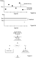
Figure 8 shows an example of a target vector (upper figure) and the corresponding energies for 3 splits (middle figure) and 4 splits (lower figure). Note that the model with 4 splits more closely follows the energy dynamics in the target vector. -
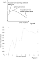
Figure 9 is a diagram showing a trade-off in splitting target vector for gain-shape quantization. Low number of splits cannot normalize shape vector sufficiently well. High number of splits requires large bit overhead for transmitting the gains, and as a consequence, not sufficient number of bits are left for the shape coding. -
Figure 10 shows an example of a target vector and the corresponding segment energies for 2 and 3-way split. -
Figure 11 is a diagram showing variance of segment energies as a function of number of segments the target vector infigure 10 is split into. -
Figures 12a-14 illustrate different implementations of an encoder and/or decoder according to exemplifying embodiments. -
Figure 15 illustrates an encoder according to exemplifying embodiments. -
Figure 16 illustrates a decoder according to exemplifying embodiments. - A concept of embodiments described herein is to analyze the shape and determine a suitable resolution into sub-vectors, given a target vector of a certain size. This may reduce the quantization error, and increase perceived quality, in case of audio codec. Further, it is an aim of some embodiments described herein to find an optimal number of sections, i.e. number of splits of the target vector.
- Embodiments herein relate to a method for supporting split gain shape vector encoding. The method is intended to be performed by a media encoder in situations where the encoding of each vector segment is subjected to a constraint related to a maximum number of bits, BMAX. That is, in situations where the maximum number of bits allowed for encoding of a vector segment is BMAX. This constraint may be due to e.g. processing capacity and/or memory capacity of the media encoder. A method according to an exemplifying embodiment will be described below with reference to
figure 1 . The method illustrated infigure 1 comprises, for a target vector x, determining 101 an initial number, Np_init, of segments for the target vector x. The number Np_init could be determined based on e.g. BMAX and a bit budget, i.e. the number of bits allocated for encoding the entire vector x. The method further comprises determining 102 an average number of bits per segment, BAVG, based on the vector bit budget and Np_init. Note that the vector x need not actually be split on this stage, even though an initial number of segments and an average number of bits available for an initial vector segment have been determined. The method further comprises determining 103 a final number, Np, of segments to be used in the gain shape vector encoding, based on energies of the Np_init segments and a difference between BMAX and BAVG. By determining a final number of segments based on these paramters, an efficient allocation of the bits of the bit budget over the target vector is enabled, which will be described more in detail further below. The determining of a number of segments could alternatively be expressed as determining a number of splits, since the number of segments and the number of splits are closely related. Alternatively, the term split could be used to denote a segment. - The determined final number, Np, of segments may then be indicated to a media decoder, in order to enable the media decoder to adequately decode the encoded gain shape vector. It should be noted that it is not necessarily the actual number of segments that is indicated, but rather a change as compared to the determined initial number of segments. Regarding the determining of Np_init, this initial number of segments may be given for the encoder and decoder. In such cases the term "determining" would refer e.g. to establishing Np_init for use, or similar.
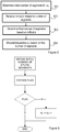
- In one embodiment, illustrated in
figure 2 , the determining of a final number of segments comprises increasing 204 the number of segments (and splits) when a relation between the energies of the Np_init segments and the difference between BMAX and BAVG fulfills a criterion. By "increasing" the number of segments is here meant increasing, as compared to the initial number Np_init, of segments. For example, the increase could be by one split (and segment), resulting in a final number of segments of Np= Np_init + 1. The increase of the number of segments could then be indicated 205 to a media decoder in a suitable manner. It is advantageous to use as few bits as possible for indicating the final number of segments to a decoder. When the increase is a predetermined number of segments (or splits), e.g. one, the final increased number of segments (or splits), could be indicated to the media decoder using a single bit, which is often referred to as a flag. For example, the bit could be set to "1", or "true", when an increased number of segments is applied, and be set to "0", or "false", when the initial number of segments is to be used. That is, the determining of a final number of segments may further comprise to determine 206 that the initial number, Np_init, of segments, should be used, i.e. Np=Np_init when the relation between the energies of the Np_init segments and the difference between BMAX and BAVG does not fulfill the criterion, or, when a corresponding criterion is not met. This is illustrated as theaction 206 infigure 2 . - The determining of a final number, Np, of segments may comprise increasing 204 the number of segments, as compared to the initial number, for the target vector x, when a maximum deviation, of a target vector segment energy, from an average per-segment energy value, EAVG, for the target vector x is larger than a threshold based on the difference between BMAX and BAVG. That is, an energy variation over the target vector segments may be compared to a threshold based on the difference between BMAX and BAVG. The logic behind using a maximum deviation from an average per-segment energy value, EAVG is, described in a simplified manner, that when there are large deviations from an average per-segment energy, there are large differences in the perceptual importance of the different segments. It should be noted that the "threshold" comparison could be expressed the other way around, such that the difference between BMAX and BAVG is compared to a threshold, which depends on, or is based on the energies of the Np_init segments. That is, the above could be expressed as that when the difference between BMAX and BAVG is smaller than a threshold depending on a maximum deviation, of a target vector segment energy, from an average per-segment energy value, EAVG, for the target vector x, the number of segments should be increased, etc. For example, this could be expressed as that the number of splits should be increased when M > α(BMAX - BAVG ), or, when


- Regarding the energies of the segments, the log-energy per-segment may be calculated as:

- The average per-segment energy may then be defined as:

- A measure of energy variations may then be defined as the absolute maximum log energy deviation from the mean as:

- The determining, or decision, of when to add an additional split may be based on testing whether the energy variation measure M is above a certain threshold based on BMAX and BAVG as:

-
Figure 3a illustrates a mean energy per segment (black dots) and total average energy EAVG (average of the segment averages). To minimize the coding distortion, it is desired to use more bits for encoding segments comprising more energy than for encoding segments comprising less energy. Thus, when there is large variation in energy between segments, it would be desired to reallocate bits from segments comprising less energy to segments comprising more energy, assuming that all segments initially are allocated at least approximately BAVG bits, i.e. assuming an initial even distribution of the bits over the segments.Figure 3b is a simple graph illustrating a number of segments, a BMAX value and a BAVG value. When the difference between BMAX and BAVG, which could also be denoted the headroom herein, is "small", e.g. smaller than a threshold, it will not be possible to reallocate that many bits to the high energy content segments, before reaching BMAX. However, by increasing the number of segments, BAVG will be reduced, which is illustrated by a dashed arrow infigure 3a , and thus increase the possibility to allocate more bits to high energy content segments. By increasing the number of segments, a higher positive deviation, in number of bits, is allowed from BAVG, which enables reallocation of bits. The maximum allowed positive deviation is BMAX - BAVG. The term reallocation here does not imply that an average number BAVG of bits is actually allocated to each segment before reallocating, but is only used to facilitate understanding of the solution provided herein. - An exemplifying embodiment could be described as: when an energy variation between the vector segments is "large" in relation to a headroom, BMAX - BAVG, the number of splits and segments is increased by "1", which is then indicated to a decoder by the setting of a one-bit flag. The determining of "large" may be performed by use of a threshold value, which may be selected based on e.g. simulations. This embodiment is illustrated in
figure 4 . Infigure 4 , the energy variation is denoted M, and in this example, the threshold MTHR is based on BMAX - BAVG. Different examples of expressions for an energy variation will be described further below. - Since the difference between BMAX and BAVG, i.e. the headroom, is a number of bits, which should be compared to an energy variation, e.g. a maximum deviation from an average, which is an energy measure, a tuning parameter α may be used to make the decision threshold proportional to the headroom. A value of α may be derived e.g. based on simulations.
- Further, there are situations where it is not considered meaningful to perform the analysis of the number of segments described above. By analysis is here meant the determining 102 of BAVG and the determining 103 of a final number of segments. In such situations, it is not desired to perform the analysis or to waste bits on indicating a number of segments to the decoder. Therefore, the performing of the analysis, and the indicating of a result, may be conditioned, i.e. only be performed when at least one additional condition is met. One such additional condition may be that the vector bit budget is above a threshold. The reason for such a condition would be that when the bit budget is low, there are not that many bits to reallocate to other segments. Another additional condition could be that the initial number of splits or sections should be below a threshold. The reason for such a condition would be e.g. complexity constraints.
- It should be noted that the embodiments described above are intended to be non-recursive, which implies a low complexity. This may be advantageous, as compared to more resource-demanding recursive methods. It should further be note that the segments are intended to be at least approximately evenly distributed over the vector, i.e. be of, at least approximately, equal size. This may also be an advantage, as compared to methods generating segments of very different sizes.
- Embodiments herein further relate to a method for supporting split gain shape vector decoding. The method corresponds to the encoding method described above. The method is intended to be performed by a media decoder in situations where a representation of each vector segment of a gain shape vector x is subjected to a constraint related to a maximum number of bits, BMAX, allowed for encoding a vector segment. The term "media" is here intended to refer to e.g. audio and/or video. A method according to an exemplifying embodiment will be described below with reference to
figure 5 . The method illustrated infigure 5 comprises determining 501 an initial number, Np_init, of segments, for a vector to be reconstructed xq; The method further comprises receiving 502 an indication, from a media encoder, of whether an increased number of segments is applied for the vector xq, or not, and determining 503 a final number of segments for the decoding of the vector xq based on the initial number of segments and the received indication. The vector xq may then be decoded 504 based on the final number of segments. The indication may, in analogy with the example on the encoder side, be received in form of a bit-flag, which is set to e.g. "1" when an additional split is to be applied, Np=Np_init + 1, and to "0" when the initial number of segments is to be used, Np=Np_init. The use of a flag as indicator is also illustrated infigure 6 . - In correspondence with the encoder side, the receiving of an indication may be conditioned, and thus only performed when one or more additional conditions are met. The same conditions should be used on the encoder and decoder side. Such additional conditions may, as previously stated, be e.g. that the vector bit budget is above a threshold T1, and that the initial number of splits or segments is below a threshold T2, and/or that the bitrate per sample BSAMPLE is above a given limit. (T1 and T2 are just used to indicate that it is not the same threshold for the two cases).
- Below some more details and variants of the solution provided herein will be described. Embodiments of a media encoder and media decoder corresponding to the methods embodiments described above will be described at the end of the detailed description.
- Energy variations across a target vector can be captured by splitting the target vector into smaller sections. The benefit of the split will depend on the energy distribution of the target vector. This can be illustrated by calculating the variance σ2 of the target signal after normalizing the energies in each section. Assuming that the sections have equal size, this can be expressed as


- Typically the variance value decreases fast for the first few number of splits but then saturates, as illustrated in
figure 7 . Looking at the shape of the graph infigure 7 , the saturation point can be interpreted as the point where further resolution in more sections is not needed. Further, it may be noted that this curve will always converge to zero since the final split will result in sections containing one sample each with variance zero. An example target vector with corresponding section energies for 3 and 4-way split is shown infigure 8 . - In another embodiment, the variance of the energies among the sections/segments is compared for different split configurations, i.e. for different numbers of segments. A large increase in variance between different split configurations, e.g. 3 segments vs. 2 segments, indicates that it would be beneficial with additional splitting of the target vector. The variance V is computed as


and, with the average energy per coefficient:
-
Figure 10 illustrates an example target vector (upper figure) and the corresponding segment energies for 2 (middle figure) and 3-way (lower figure) split, respectively, of the example target vector. Infigure 11 , the corresponding variance of the segment energies is shown for a varying number of segments. Considering the change from 2 segments to 3 segments, the variance V is increasing, which then indicates that a split into 3 segments would be beneficial over a split into 2 segments. - In an embodiment the decision for additional split is made on basis of:where β is a lower threshold for the increase in variance of the segment energies between two consecutive number of splits. When the increase in variance is sufficient, i.e. in this example exceeds the threshold β, the number of segments is increased, e.g. by one. As previously mentioned, the use of an additional split could be signalled from the encoder to the decoder by, for example, using one bit for signalling one additional split or no additional split. However, more bits could be used for signalling more than one additional split if preferred.

- A variation on the embodiment above is to directly use the average energy per coefficient
E coeff in normalized segments as a measure of the energy variations. The motivation for doing this is that when the average energy per coefficient does not change much between two consecutive number of splits, the distribution within each segment is similar and does not benefit from further splitting, while a large change between two consecutive number of splits motivates an additional split. The decision can be made based on a threshold γ similar to the above expression:
- In another embodiment, assuming that and initial number of segments Np_init is given, e.g., due to quantizer constraints, the algorithm makes a decision to increase Np_init or not with the following procedure:
First, the log-energy per-segment is calculated as:
- The average per-segment energy is then defined as:

- A measure of energy variations is defined as the absolute maximum log energy deviation from the mean:

- The absolute is used in case it is essential to trigger on any large deviation from mean value, be it positive or negative. In some cases, only the upper limit is of importance, in which case the absolute value may be omitted, as:

- In yet another embodiment, the lower limit may be of larger importance, and the measure may then be defined to find the smallest negative deviation:

- In all exemplary embodiments of the energy deviation measure, the intent is to increase the number of splits in case the estimated energy deviation is large. The reason is that an additional split should provide slightly more freedom to allocate the bits locally, as previously described. The decision when to add an additional split may be based on testing whether the energy variation measure M is above a certain threshold MTHR as (which is also illustrated in
figure 4 ):
- In one embodiment, the decision for additional split may also be affected by the constraints on the encoder for the different sections or segments. In such cases, an additional split may be needed if the necessary bit allocation cannot be fit below the maximum number of bits for each section or segment, BMAX. As previously mentioned, the difference between the maximum number of bits per section BMAX and the average number of bits per section BAVG may be denoted the headroom for the bit allocation (BMAX - BAVG ). The average bits per band may be calculated as


- The decision to use an additional split may also be encoded as a parameter and sent from the encoder to the decoder. To ensure that the additional split signalling is only done when it is needed, e.g. since it requires an extra bit when used, the above algorithm may be restricted to be used only is situations where it may be beneficial. For instance, it may be limited to be used only when the initial number of splits or segments Np_init is below a maximum number of splits or segments, e.g. NP_init < NP,mαx and/or when the bitrate per sample BSAMPLE is above a given limit, e.g. BSAMPLE >BSAMPLE,THR. To be synchronized, the same condition should be used in the encoder and decoder for correct bitstream decoding.
- It is an advantage of the embodiments that they may improve the performance of gain-shape quantization schemes. The criterion for split requires insignificant additional computational complexity, and since quantizing smaller segments is less complex than quantizing the entire target vector, the proposed algorithm of the embodiments may also achieve a reduction in computational complexity.
- The methods and techniques described above may be implemented in encoders and decoders, which may be part of other devices.
- An exemplifying embodiment of a media encoder is illustrated in a general manner in
figure 12a . By media encoder is referred to an encoder for e.g. audio and/or video signals. Theencoder 1200 is configured to perform at least one of the method embodiments described above with reference to any offigures 1-2 and4 . Theencoder 1200 is associated with the same technical features, objects and advantages as the previously described method embodiments. The encoder will be described in brief in order to avoid unnecessary repetition. - The encoder may be implemented and/or described as follows:
Theencoder 1200 is configured for split gain shape vector encoding. Theencoder 1200 comprises processing circuitry, or processing means 1201 and acommunication interface 1202. Theprocessing circuitry 1201 is configured to cause theencoder 1200 to, for a target shape vector x: determine an initial number Np_init of segments, and further to determine an average number of bits per segment, BAVG, based on a vector bit budget and Np_init. Theprocessing circuitry 1201 is further configured to cause the encoder to determine a final number of segments to be used in the gain shape vector encoding based on energies of the Np_init segments and a difference between BMAX and BAVG. Thecommunication interface 1202, which may also be denoted e.g. Input/Output (I/O) interface, includes an interface for sending data to and receiving data from other entities or modules. - The
processing circuitry 1201 could, as illustrated infigure 12b , comprise processing means, such as aprocessor 1203, e.g. a CPU, and amemory 1204 for storing or holding instructions. The memory would then comprise instructions, e.g. in form of acomputer program 1205, which when executed by the processing means 1203 causes theencoder 1200 to perform the actions described above. - An alternative implementation of the
processing circuitry 1201 is shown infigure 12c . The processing circuitry here comprises a first determiningunit 1206, configured to cause theencoder 1200 to: determine an initial number Np_init of segments for a target shape vector x. The processing circuitry further comprises a second determiningunit 1207 configured to cause the encoder to determine an average number of bits per segment, BAVG, based on a vector bit budget and Np_init. The processing circuitry further comprises a third determiningunit 1208, configured to cause the encoder to determine a final number of segments, for the vector x, to be used in the gain shape vector encoding, based on energies of the Np_init segments and a difference between BMAX and BAVG. Theprocessing circuitry 1201 could comprise more units, such as an indicatingunit 1209 configured to cause the encoder to indicate the final number of segments, e.g. an increase by one segment as compared to the initial number, to a media decoder. This task could alternatively be performed by one of the other units. - The encoders described above could be configured for the different method embodiments described herein, such as increasing the number of segments, as compared to the initial number, for the target vector x for the gain shape vector encoding when a maximum deviation, of a target vector segment energy, from an average per-segment energy value, EAVG, for the target vector x is larger than a threshold based on the difference between BMAX and BAVG.
- The
encoder 1200 may be assumed to comprise further functionality, for carrying out regular encoder functions. - Embodiments herein also relate to a
media decoder 1300 configured for carrying out embodiments of the decoding method described above. That is, the method for supporting split gain shape vector decoding, illustrated e.g. infigure 5 . An exemplifying embodiment of adecoder 1300 is illustrated in a general manner infigure 13a . Thedecoder 1300 is configured to perform at least one of the method embodiments described above with reference tofigures 5-6 . Thedecoder 1300 is associated with the same technical features, objects and advantages as the previously described method embodiments. The decoder will be described in brief in order to avoid unnecessary repetition. - The
decoder 1300 is configured for supporting split gain shape vector decoding, and is operable to perform split gain shape vector decoding. Thedecoder 1300 comprisesprocessing circuitry 1301 and acommunication interface 1302. Theprocessing circuitry 1301 is configured to cause the network node to determine an initial number Np_init, for a vector xq to be reconstructed; and further to receive an indication, from a media encoder, of whether an increased number of segments is applied for the vector xq, or not. Theprocessing circuitry 1301 is further configured to cause the network node to determine a final number of segments for the decoding of the vector xq based on the received indication. Thecommunication interface 1302, which may also be denoted e.g. Input/Output (I/O) interface, includes an interface for sending data to and receiving data from other entities or modules. - The
processing circuitry 1301 could, as illustrated infigure 13b , comprise processing means, such as aprocessor 1303, and amemory 1304 for storing or holding instructions. The memory would then comprise instructions, e.g. in form ofcomputer program 1305, which when executed by the processing means 1303 causes thenetwork node 1300 to perform the actions described above. - An alternative implementation of the
processing circuitry 1301 is shown infigure 13c . The processing circuitry here comprises a first determiningunit 1306, configured to cause the network node to determine an initial number of segments, Np_init, for a vector xq to be reconstructed. Theprocessing circuitry 1301 further comprises areceiving unit 1307, configured to cause the network node to receive an indication, from a media encoder, of whether an increased number of segments is applied for the vector xq, or not. Theprocessing circuitry 1301 further comprises a second determiningunit 1308, configured to cause the network node to determine a final number of segments for the decoding of the vector xq based on the received indication. - The
network node 1300 may be assumed to comprise further functionality, for carrying out regular decoder functions. - The encoder and decoder could alternatively be described and/or implemented as illustrated in
figure 14. Figure 14 is a schematic block diagram of a split algorithm encoder and decoder according to embodiments of the herein suggested solution. The encoder comprises an initial split decider unit, an energy variation analyzer unit, and a split encoder unit. The decoder comprises an initial split decider, and a decision decoder. The encoder and the decoder with its included units could be implemented in hardware and/or software. - The encoder and decoder described herein could alternatively be implemented e.g. by one or more of a processor and adequate software with suitable storage or memory therefore, in order to perform the determining of an adequate number of splits and/or segments of an input vector, according to the embodiments described herein, see
figures 15 and 16 . For the encoder illustrated infigure 15 , the incoming vector is received by an input (IN), to which the processor and the memory are connected, and the encoded representation of the vector, e.g. an audio signal (parameters), obtained from the software is outputted from the output (OUT). - The decoder described herein could be implemented e.g. by one or more of a processor and adequate software with suitable storage or memory therefore, in order to perform the decoding of the input parameters, according to the embodiments described herein, see
figure 16 . The incoming parameters are received by an input (IN), to which the processor and the memory are connected, and the decoded signal obtained from the software is outputted from the output (OUT). - The technology described above may be comprised e.g. in a wireless device such as e.g. a user equipment, a mobile terminal, a tablet, a mobile wireless device for machine-to-machine communication, an integrated or embedded wireless card, an externally plugged in wireless card, a dongle, etc, or in a stationary or semi stationary device, such as a personal computer or a smart TV.
- The steps, functions, procedures, modules, units and/or blocks described herein may be implemented in hardware using any conventional technology, such as discrete circuit or integrated circuit technology, including both general-purpose electronic circuitry and application-specific circuitry.
- Particular examples include one or more suitably configured digital signal processors and other known electronic circuits, e.g. discrete logic gates interconnected to perform a specialized function, or Application Specific Integrated Circuits (ASICs).
- Alternatively, at least some of the steps, functions, procedures, modules, units and/or blocks described above may be implemented in software such as a computer program for execution by suitable processing circuitry including one or more processing units. The software could be carried by a carrier, such as an electronic signal, an optical signal, a radio signal, or a computer readable storage medium before and/or during the use of the computer program in the network nodes.
- The flow diagram or diagrams presented herein may be regarded as a computer flow diagram or diagrams, when performed by one or more processors. A corresponding apparatus may be defined as a group of function modules, where each step performed by the processor corresponds to a function module. In this case, the function modules are implemented as a computer program running on the processor.
- Examples of processing circuitry includes, but is not limited to, one or more microprocessors, one or more Digital Signal Processors, DSPs, one or more Central Processing Units, CPUs, and/or any suitable programmable logic circuitry such as one or more Field Programmable Gate Arrays, FPGAs, or one or more Programmable Logic Controllers, PLCs. That is, the units or modules in the arrangements in the different nodes described above could be implemented by a combination of analog and digital circuits, and/or one or more processors configured with software and/or firmware, e.g. stored in a memory. One or more of these processors, as well as the other digital hardware, may be included in a single application-specific integrated circuitry, ASIC, or several processors and various digital hardware may be distributed among several separate components, whether individually packaged or assembled into a system-on-a-chip, SoC.
- It should also be understood that it may be possible to re-use the general processing capabilities of any conventional device or unit in which the proposed technology is implemented. It may also be possible to re-use existing software, e.g. by reprogramming of the existing software or by adding new software components.
-
- Np
- number of sections
- E
- logarithm of segment energy
- EAVG
- average segment energy over segments of a target vector
- BMAX
- maximum allowed bits per segment
- BAVG
- average bits per segment
- BSAMPLE
- bits per sample
- BBAND
- allocated bits for a given band
- BW
- band width
- x
- target vector
- r
- shape vector (also called residual)
- G
- gain (scalar or vector) for scaling target vector
- i
- segment index
- k
- sample index
Claims (10)
- A method for gain shape vector quantization of a target vector x comprising plurality of coefficients derived from an audio signal, where a gain of the target vector x is quantized by a gain quantizer and a shape of the target vector x is quantized by a split vector quantizer, and where a maximum number of bits, BMAX, allowed for quantizing a vector segment is constrained by the split vector Quantizer, the method being performed by an audio encoder, the method comprising:- determining an initial number, Np_init, of segments for the target vector x based on a ratio between a number of bits allocated for quantizing the shape of the target vector x and BMAX;- determining energy of each Np_init target vector segment by summing energies of vector coefficients;- determining an average number of bits per segment, BAVG, based on a ratio between the number of bits allocated for quantizing the shape of the target vector x and Np_init;- determining a final number. Np, of segments by increasing the initial number Np_init of segments by one if a maximum deviation of a target vector segment energy from an average per-segment energy value, EAVG, is larger than a threshold proportional to the difference between BMAX and BAVG;- providing the final number Np to the split vector quantizer to be used in Quantization of the shape of the target vector x; and- indicating the increase of the number of segments to an audio decoder.
- The method according to claim 1, wherein energy of each target vector segment is computed as log-energy per segment.
- The method according to claim 2, wherein log-energy per segment is computed as:

- The method according to any of the preceding claims, wherein the determining of whether to increase the initial number of segments is only performed when at least one additional condition is met.
- The method according to any of the preceding claims, wherein the determining of whether to increase the initial number of segments is performed when the initial number of segments is below a threshold and/or when a bitrate per sample is above a given limit.
- An audio encoder (1200), operable to perform gain shape vector quantization of a target vector x comprising plurality of coefficients derived from an audio signal, where a gain of the target vector x is quantized by a gain quantizer and a shape of the target vector is Quantized by a split vector quantizer and, where a maximum number of bits, BMAX, allowed for quantizing a vector segment is constrained by the split vector quantizer, the audio encoder being configured to:- determine an initial number, Np_init, of segments for the target vector x based on a ratio between a number of bits allocated for quantizing the shape of the target vector x and BMAX;- determine energy of each Np_init target vector segment by summing energies of vector coefficients;- determine an average number of bits per segment, BAVG, based on a ratio between the number of bits allocated for quantizing the shape of the target vector x and Np_init;- determine a final number. Np, of segments by increasing the initial number Np_init of segments by one if a maximum deviation of a target vector segment energy from an average per-segment energy value, EAVG, is larger than a threshold proportional to the difference between BMAX and BAVG- provide the final number Np to the split vector Quantizer to be used in Quantization of the shape of the target vector x; and- indicate the increase of the number of segments to an audio decoder.
- The audio encoder according to claim 6 further configured to perform the method according to at least one of claims 2 to 5.
- A wireless device comprising the audio encoder according to claim 6.
- Computer program (1205, 1305) comprising instructions which, when executed on at least one processor, cause the at least one processor to carry out the method according to at least one of claims 1 to 5.
- A carrier containing the computer program of the previous claim, wherein the carrier is one of an electronic signal, optical signal, radio signal or computer readable storage medium.
Priority Applications (4)
| Application Number | Priority Date | Filing Date | Title |
|---|---|---|---|
| PL14805698T PL3069449T3 (en) | 2013-11-12 | 2014-11-11 | Split gain shape vector coding |
| EP21185475.7A EP3913808A1 (en) | 2013-11-12 | 2014-11-11 | Split gain shape vector coding |
| EP19186188.9A EP3624347B1 (en) | 2013-11-12 | 2014-11-11 | Split gain shape vector coding |
| DK19186188.9T DK3624347T3 (en) | 2013-11-12 | 2014-11-11 | Coding for shared gain form vector |
Applications Claiming Priority (2)
| Application Number | Priority Date | Filing Date | Title |
|---|---|---|---|
| US201361903024P | 2013-11-12 | 2013-11-12 | |
| PCT/SE2014/051339 WO2015072914A1 (en) | 2013-11-12 | 2014-11-11 | Split gain shape vector coding |
Related Child Applications (3)
| Application Number | Title | Priority Date | Filing Date |
|---|---|---|---|
| EP19186188.9A Division EP3624347B1 (en) | 2013-11-12 | 2014-11-11 | Split gain shape vector coding |
| EP19186188.9A Division-Into EP3624347B1 (en) | 2013-11-12 | 2014-11-11 | Split gain shape vector coding |
| EP21185475.7A Division EP3913808A1 (en) | 2013-11-12 | 2014-11-11 | Split gain shape vector coding |
Publications (2)
| Publication Number | Publication Date |
|---|---|
| EP3069449A1 EP3069449A1 (en) | 2016-09-21 |
| EP3069449B1 true EP3069449B1 (en) | 2020-01-08 |
Family
ID=52001045
Family Applications (3)
| Application Number | Title | Priority Date | Filing Date |
|---|---|---|---|
| EP21185475.7A Pending EP3913808A1 (en) | 2013-11-12 | 2014-11-11 | Split gain shape vector coding |
| EP14805698.9A Active EP3069449B1 (en) | 2013-11-12 | 2014-11-11 | Split gain shape vector coding |
| EP19186188.9A Active EP3624347B1 (en) | 2013-11-12 | 2014-11-11 | Split gain shape vector coding |
Family Applications Before (1)
| Application Number | Title | Priority Date | Filing Date |
|---|---|---|---|
| EP21185475.7A Pending EP3913808A1 (en) | 2013-11-12 | 2014-11-11 | Split gain shape vector coding |
Family Applications After (1)
| Application Number | Title | Priority Date | Filing Date |
|---|---|---|---|
| EP19186188.9A Active EP3624347B1 (en) | 2013-11-12 | 2014-11-11 | Split gain shape vector coding |
Country Status (12)
| Country | Link |
|---|---|
| US (3) | US9385750B2 (en) |
| EP (3) | EP3913808A1 (en) |
| CN (3) | CN110649925B (en) |
| AR (2) | AR099351A1 (en) |
| BR (1) | BR112016009785B1 (en) |
| DK (2) | DK3069449T3 (en) |
| ES (2) | ES2773958T3 (en) |
| MX (3) | MX365684B (en) |
| PL (1) | PL3069449T3 (en) |
| PT (2) | PT3069449T (en) |
| TW (3) | TWI776298B (en) |
| WO (1) | WO2015072914A1 (en) |
Families Citing this family (6)
| Publication number | Priority date | Publication date | Assignee | Title |
|---|---|---|---|---|
| FI3547261T3 (en) * | 2012-03-29 | 2023-09-26 | Ericsson Telefon Ab L M | Vector quantizer |
| MX365684B (en) * | 2013-11-12 | 2019-06-11 | Ericsson Telefon Ab L M | Split gain shape vector coding. |
| NZ726879A (en) | 2014-07-28 | 2017-10-27 | ERICSSON TELEFON AB L M (publ) | Pyramid vector quantizer shape search |
| US10559315B2 (en) | 2018-03-28 | 2020-02-11 | Qualcomm Incorporated | Extended-range coarse-fine quantization for audio coding |
| US10762910B2 (en) | 2018-06-01 | 2020-09-01 | Qualcomm Incorporated | Hierarchical fine quantization for audio coding |
| CN111061907B (en) * | 2019-12-10 | 2023-06-20 | 腾讯科技(深圳)有限公司 | Media data processing method, device and storage medium |
Family Cites Families (11)
| Publication number | Priority date | Publication date | Assignee | Title |
|---|---|---|---|---|
| US7310598B1 (en) * | 2002-04-12 | 2007-12-18 | University Of Central Florida Research Foundation, Inc. | Energy based split vector quantizer employing signal representation in multiple transform domains |
| US7343291B2 (en) * | 2003-07-18 | 2008-03-11 | Microsoft Corporation | Multi-pass variable bitrate media encoding |
| CN1327408C (en) * | 2004-12-31 | 2007-07-18 | 苏州大学 | A low bit-rate speech encoder |
| KR101768207B1 (en) * | 2010-01-19 | 2017-08-16 | 삼성전자주식회사 | Method and apparatus for encoding/decoding motion vector based on reduced motion vector predictor candidates |
| US9236063B2 (en) * | 2010-07-30 | 2016-01-12 | Qualcomm Incorporated | Systems, methods, apparatus, and computer-readable media for dynamic bit allocation |
| US9009036B2 (en) * | 2011-03-07 | 2015-04-14 | Xiph.org Foundation | Methods and systems for bit allocation and partitioning in gain-shape vector quantization for audio coding |
| DK2697795T3 (en) * | 2011-04-15 | 2015-09-07 | Ericsson Telefon Ab L M | ADAPTIVE SHARING Gain / FORM OF INSTALLMENTS |
| US20130132100A1 (en) * | 2011-10-28 | 2013-05-23 | Electronics And Telecommunications Research Institute | Apparatus and method for codec signal in a communication system |
| US9860604B2 (en) * | 2011-11-23 | 2018-01-02 | Oath Inc. | Systems and methods for internet video delivery |
| JP2013131918A (en) * | 2011-12-21 | 2013-07-04 | Jvc Kenwood Corp | Video decoder, video decoding method and video decoding program |
| MX365684B (en) * | 2013-11-12 | 2019-06-11 | Ericsson Telefon Ab L M | Split gain shape vector coding. |
-
2014
- 2014-11-11 MX MX2017013371A patent/MX365684B/en unknown
- 2014-11-11 EP EP21185475.7A patent/EP3913808A1/en active Pending
- 2014-11-11 EP EP14805698.9A patent/EP3069449B1/en active Active
- 2014-11-11 CN CN201911003152.6A patent/CN110649925B/en active Active
- 2014-11-11 BR BR112016009785-8A patent/BR112016009785B1/en active IP Right Grant
- 2014-11-11 DK DK14805698.9T patent/DK3069449T3/en active
- 2014-11-11 PT PT148056989T patent/PT3069449T/en unknown
- 2014-11-11 CN CN201480061092.2A patent/CN105706369B/en active Active
- 2014-11-11 MX MX2016005806A patent/MX352106B/en active IP Right Grant
- 2014-11-11 EP EP19186188.9A patent/EP3624347B1/en active Active
- 2014-11-11 DK DK19186188.9T patent/DK3624347T3/en active
- 2014-11-11 US US14/440,713 patent/US9385750B2/en active Active
- 2014-11-11 ES ES14805698T patent/ES2773958T3/en active Active
- 2014-11-11 WO PCT/SE2014/051339 patent/WO2015072914A1/en active Application Filing
- 2014-11-11 CN CN201911003154.5A patent/CN110708075B/en active Active
- 2014-11-11 PT PT191861889T patent/PT3624347T/en unknown
- 2014-11-11 ES ES19186188T patent/ES2891050T3/en active Active
- 2014-11-11 PL PL14805698T patent/PL3069449T3/en unknown
- 2014-11-12 TW TW109142236A patent/TWI776298B/en active
- 2014-11-12 AR ARP140104266A patent/AR099351A1/en active IP Right Grant
- 2014-11-12 TW TW103139294A patent/TWI669943B/en active
- 2014-11-12 TW TW108125153A patent/TWI708501B/en active
-
2016
- 2016-05-04 MX MX2019006311A patent/MX2019006311A/en unknown
- 2016-06-22 US US15/189,627 patent/US9602128B2/en active Active
-
2017
- 2017-02-07 US US15/426,483 patent/US9853659B2/en active Active
-
2018
- 2018-02-01 AR ARP180100239A patent/AR111014A2/en active IP Right Grant
Non-Patent Citations (1)
| Title |
|---|
| MAKHOUL J ET AL: "VECTOR QUANTIZATION IN SPEECH CODING", PROCEEDINGS OF THE IEEE, IEEE. NEW YORK, US, vol. 73, no. 11, 1 November 1985 (1985-11-01), pages 1551 - 1588, XP000601753, ISSN: 0018-9219 * |
Also Published As
Similar Documents
| Publication | Publication Date | Title |
|---|---|---|
| US9853659B2 (en) | Split gain shape vector coding | |
| US10841584B2 (en) | Method and apparatus for pyramid vector quantization de-indexing of audio/video sample vectors | |
| JP6698897B2 (en) | Coding and decoding of spectral peak positions | |
| JP6494741B2 (en) | Encoding apparatus, decoding apparatus, system and method for encoding and decoding | |
| US9741349B2 (en) | Audio coding method and apparatus | |
| US8593321B2 (en) | Computation apparatus and method, quantization apparatus and method, and program | |
| US20190141316A1 (en) | Hybrid Digital-Analog Coding | |
| US7650277B2 (en) | System, method, and apparatus for fast quantization in perceptual audio coders | |
| US8601039B2 (en) | Computation apparatus and method, quantization apparatus and method, and program | |
| JP5379871B2 (en) | Quantization for audio coding |
Legal Events
| Date | Code | Title | Description |
|---|---|---|---|
| PUAI | Public reference made under article 153(3) epc to a published international application that has entered the european phase |
Free format text: ORIGINAL CODE: 0009012 |
|
| 17P | Request for examination filed |
Effective date: 20160610 |
|
| AK | Designated contracting states |
Kind code of ref document: A1 Designated state(s): AL AT BE BG CH CY CZ DE DK EE ES FI FR GB GR HR HU IE IS IT LI LT LU LV MC MK MT NL NO PL PT RO RS SE SI SK SM TR |
|
| AX | Request for extension of the european patent |
Extension state: BA ME |
|
| DAX | Request for extension of the european patent (deleted) | ||
| STAA | Information on the status of an ep patent application or granted ep patent |
Free format text: STATUS: EXAMINATION IS IN PROGRESS |
|
| 17Q | First examination report despatched |
Effective date: 20180215 |
|
| GRAP | Despatch of communication of intention to grant a patent |
Free format text: ORIGINAL CODE: EPIDOSNIGR1 |
|
| STAA | Information on the status of an ep patent application or granted ep patent |
Free format text: STATUS: GRANT OF PATENT IS INTENDED |
|
| GRAS | Grant fee paid |
Free format text: ORIGINAL CODE: EPIDOSNIGR3 |
|
| GRAJ | Information related to disapproval of communication of intention to grant by the applicant or resumption of examination proceedings by the epo deleted |
Free format text: ORIGINAL CODE: EPIDOSDIGR1 |
|
| GRAL | Information related to payment of fee for publishing/printing deleted |
Free format text: ORIGINAL CODE: EPIDOSDIGR3 |
|
| STAA | Information on the status of an ep patent application or granted ep patent |
Free format text: STATUS: EXAMINATION IS IN PROGRESS |
|
| INTG | Intention to grant announced |
Effective date: 20191016 |
|
| GRAR | Information related to intention to grant a patent recorded |
Free format text: ORIGINAL CODE: EPIDOSNIGR71 |
|
| STAA | Information on the status of an ep patent application or granted ep patent |
Free format text: STATUS: GRANT OF PATENT IS INTENDED |
|
| GRAA | (expected) grant |
Free format text: ORIGINAL CODE: 0009210 |
|
| STAA | Information on the status of an ep patent application or granted ep patent |
Free format text: STATUS: THE PATENT HAS BEEN GRANTED |
|
| INTC | Intention to grant announced (deleted) | ||
| AK | Designated contracting states |
Kind code of ref document: B1 Designated state(s): AL AT BE BG CH CY CZ DE DK EE ES FI FR GB GR HR HU IE IS IT LI LT LU LV MC MK MT NL NO PL PT RO RS SE SI SK SM TR |
|
| INTG | Intention to grant announced |
Effective date: 20191129 |
|
| REG | Reference to a national code |
Ref country code: GB Ref legal event code: FG4D |
|
| REG | Reference to a national code |
Ref country code: CH Ref legal event code: EP |
|
| REG | Reference to a national code |
Ref country code: DE Ref legal event code: R096 Ref document number: 602014059761 Country of ref document: DE |
|
| REG | Reference to a national code |
Ref country code: IE Ref legal event code: FG4D |
|
| REG | Reference to a national code |
Ref country code: AT Ref legal event code: REF Ref document number: 1223953 Country of ref document: AT Kind code of ref document: T Effective date: 20200215 |
|
| REG | Reference to a national code |
Ref country code: NL Ref legal event code: FP |
|
| REG | Reference to a national code |
Ref country code: PT Ref legal event code: SC4A Ref document number: 3069449 Country of ref document: PT Date of ref document: 20200323 Kind code of ref document: T Free format text: AVAILABILITY OF NATIONAL TRANSLATION Effective date: 20200306 |
|
| REG | Reference to a national code |
Ref country code: DK Ref legal event code: T3 Effective date: 20200408 |
|
| REG | Reference to a national code |
Ref country code: NO Ref legal event code: T2 Effective date: 20200108 |
|
| REG | Reference to a national code |
Ref country code: LT Ref legal event code: MG4D |
|
| REG | Reference to a national code |
Ref country code: ES Ref legal event code: FG2A Ref document number: 2773958 Country of ref document: ES Kind code of ref document: T3 Effective date: 20200715 |
|
| PG25 | Lapsed in a contracting state [announced via postgrant information from national office to epo] |
Ref country code: LT Free format text: LAPSE BECAUSE OF FAILURE TO SUBMIT A TRANSLATION OF THE DESCRIPTION OR TO PAY THE FEE WITHIN THE PRESCRIBED TIME-LIMIT Effective date: 20200108 Ref country code: RS Free format text: LAPSE BECAUSE OF FAILURE TO SUBMIT A TRANSLATION OF THE DESCRIPTION OR TO PAY THE FEE WITHIN THE PRESCRIBED TIME-LIMIT Effective date: 20200108 Ref country code: FI Free format text: LAPSE BECAUSE OF FAILURE TO SUBMIT A TRANSLATION OF THE DESCRIPTION OR TO PAY THE FEE WITHIN THE PRESCRIBED TIME-LIMIT Effective date: 20200108 |
|
| PG25 | Lapsed in a contracting state [announced via postgrant information from national office to epo] |
Ref country code: IS Free format text: LAPSE BECAUSE OF FAILURE TO SUBMIT A TRANSLATION OF THE DESCRIPTION OR TO PAY THE FEE WITHIN THE PRESCRIBED TIME-LIMIT Effective date: 20200508 Ref country code: SE Free format text: LAPSE BECAUSE OF FAILURE TO SUBMIT A TRANSLATION OF THE DESCRIPTION OR TO PAY THE FEE WITHIN THE PRESCRIBED TIME-LIMIT Effective date: 20200108 Ref country code: LV Free format text: LAPSE BECAUSE OF FAILURE TO SUBMIT A TRANSLATION OF THE DESCRIPTION OR TO PAY THE FEE WITHIN THE PRESCRIBED TIME-LIMIT Effective date: 20200108 Ref country code: HR Free format text: LAPSE BECAUSE OF FAILURE TO SUBMIT A TRANSLATION OF THE DESCRIPTION OR TO PAY THE FEE WITHIN THE PRESCRIBED TIME-LIMIT Effective date: 20200108 Ref country code: GR Free format text: LAPSE BECAUSE OF FAILURE TO SUBMIT A TRANSLATION OF THE DESCRIPTION OR TO PAY THE FEE WITHIN THE PRESCRIBED TIME-LIMIT Effective date: 20200409 Ref country code: BG Free format text: LAPSE BECAUSE OF FAILURE TO SUBMIT A TRANSLATION OF THE DESCRIPTION OR TO PAY THE FEE WITHIN THE PRESCRIBED TIME-LIMIT Effective date: 20200408 |
|
| REG | Reference to a national code |
Ref country code: DE Ref legal event code: R097 Ref document number: 602014059761 Country of ref document: DE |
|
| PG25 | Lapsed in a contracting state [announced via postgrant information from national office to epo] |
Ref country code: SM Free format text: LAPSE BECAUSE OF FAILURE TO SUBMIT A TRANSLATION OF THE DESCRIPTION OR TO PAY THE FEE WITHIN THE PRESCRIBED TIME-LIMIT Effective date: 20200108 Ref country code: EE Free format text: LAPSE BECAUSE OF FAILURE TO SUBMIT A TRANSLATION OF THE DESCRIPTION OR TO PAY THE FEE WITHIN THE PRESCRIBED TIME-LIMIT Effective date: 20200108 Ref country code: RO Free format text: LAPSE BECAUSE OF FAILURE TO SUBMIT A TRANSLATION OF THE DESCRIPTION OR TO PAY THE FEE WITHIN THE PRESCRIBED TIME-LIMIT Effective date: 20200108 Ref country code: SK Free format text: LAPSE BECAUSE OF FAILURE TO SUBMIT A TRANSLATION OF THE DESCRIPTION OR TO PAY THE FEE WITHIN THE PRESCRIBED TIME-LIMIT Effective date: 20200108 |
|
| PLBE | No opposition filed within time limit |
Free format text: ORIGINAL CODE: 0009261 |
|
| STAA | Information on the status of an ep patent application or granted ep patent |
Free format text: STATUS: NO OPPOSITION FILED WITHIN TIME LIMIT |
|
| REG | Reference to a national code |
Ref country code: AT Ref legal event code: MK05 Ref document number: 1223953 Country of ref document: AT Kind code of ref document: T Effective date: 20200108 |
|
| 26N | No opposition filed |
Effective date: 20201009 |
|
| PG25 | Lapsed in a contracting state [announced via postgrant information from national office to epo] |
Ref country code: AT Free format text: LAPSE BECAUSE OF FAILURE TO SUBMIT A TRANSLATION OF THE DESCRIPTION OR TO PAY THE FEE WITHIN THE PRESCRIBED TIME-LIMIT Effective date: 20200108 |
|
| PG25 | Lapsed in a contracting state [announced via postgrant information from national office to epo] |
Ref country code: SI Free format text: LAPSE BECAUSE OF FAILURE TO SUBMIT A TRANSLATION OF THE DESCRIPTION OR TO PAY THE FEE WITHIN THE PRESCRIBED TIME-LIMIT Effective date: 20200108 |
|
| PG25 | Lapsed in a contracting state [announced via postgrant information from national office to epo] |
Ref country code: MC Free format text: LAPSE BECAUSE OF FAILURE TO SUBMIT A TRANSLATION OF THE DESCRIPTION OR TO PAY THE FEE WITHIN THE PRESCRIBED TIME-LIMIT Effective date: 20200108 |
|
| REG | Reference to a national code |
Ref country code: CH Ref legal event code: PL |
|
| PG25 | Lapsed in a contracting state [announced via postgrant information from national office to epo] |
Ref country code: LU Free format text: LAPSE BECAUSE OF NON-PAYMENT OF DUE FEES Effective date: 20201111 |
|
| REG | Reference to a national code |
Ref country code: BE Ref legal event code: MM Effective date: 20201130 |
|
| PG25 | Lapsed in a contracting state [announced via postgrant information from national office to epo] |
Ref country code: CH Free format text: LAPSE BECAUSE OF NON-PAYMENT OF DUE FEES Effective date: 20201130 Ref country code: LI Free format text: LAPSE BECAUSE OF NON-PAYMENT OF DUE FEES Effective date: 20201130 |
|
| PG25 | Lapsed in a contracting state [announced via postgrant information from national office to epo] |
Ref country code: MT Free format text: LAPSE BECAUSE OF FAILURE TO SUBMIT A TRANSLATION OF THE DESCRIPTION OR TO PAY THE FEE WITHIN THE PRESCRIBED TIME-LIMIT Effective date: 20200108 Ref country code: CY Free format text: LAPSE BECAUSE OF FAILURE TO SUBMIT A TRANSLATION OF THE DESCRIPTION OR TO PAY THE FEE WITHIN THE PRESCRIBED TIME-LIMIT Effective date: 20200108 |
|
| PG25 | Lapsed in a contracting state [announced via postgrant information from national office to epo] |
Ref country code: MK Free format text: LAPSE BECAUSE OF FAILURE TO SUBMIT A TRANSLATION OF THE DESCRIPTION OR TO PAY THE FEE WITHIN THE PRESCRIBED TIME-LIMIT Effective date: 20200108 Ref country code: AL Free format text: LAPSE BECAUSE OF FAILURE TO SUBMIT A TRANSLATION OF THE DESCRIPTION OR TO PAY THE FEE WITHIN THE PRESCRIBED TIME-LIMIT Effective date: 20200108 |
|
| PG25 | Lapsed in a contracting state [announced via postgrant information from national office to epo] |
Ref country code: BE Free format text: LAPSE BECAUSE OF NON-PAYMENT OF DUE FEES Effective date: 20201130 |
|
| PGFP | Annual fee paid to national office [announced via postgrant information from national office to epo] |
Ref country code: PL Payment date: 20221021 Year of fee payment: 9 |
|
| P01 | Opt-out of the competence of the unified patent court (upc) registered |
Effective date: 20230523 |
|
| PGFP | Annual fee paid to national office [announced via postgrant information from national office to epo] |
Ref country code: NL Payment date: 20231126 Year of fee payment: 10 |
|
| PGFP | Annual fee paid to national office [announced via postgrant information from national office to epo] |
Ref country code: GB Payment date: 20231127 Year of fee payment: 10 |
|
| PGFP | Annual fee paid to national office [announced via postgrant information from national office to epo] |
Ref country code: ES Payment date: 20231201 Year of fee payment: 10 |
|
| PGFP | Annual fee paid to national office [announced via postgrant information from national office to epo] |
Ref country code: TR Payment date: 20231026 Year of fee payment: 10 Ref country code: PT Payment date: 20231024 Year of fee payment: 10 Ref country code: NO Payment date: 20231129 Year of fee payment: 10 Ref country code: IT Payment date: 20231122 Year of fee payment: 10 Ref country code: IE Payment date: 20231127 Year of fee payment: 10 Ref country code: FR Payment date: 20231127 Year of fee payment: 10 Ref country code: DK Payment date: 20231127 Year of fee payment: 10 Ref country code: DE Payment date: 20231129 Year of fee payment: 10 Ref country code: CZ Payment date: 20231024 Year of fee payment: 10 |
|
| PGFP | Annual fee paid to national office [announced via postgrant information from national office to epo] |
Ref country code: PL Payment date: 20231027 Year of fee payment: 10 |