EP3913772B1 - Rotor, electric motor and electric vehicle - Google Patents
Rotor, electric motor and electric vehicle Download PDFInfo
- Publication number
- EP3913772B1 EP3913772B1 EP20831805.5A EP20831805A EP3913772B1 EP 3913772 B1 EP3913772 B1 EP 3913772B1 EP 20831805 A EP20831805 A EP 20831805A EP 3913772 B1 EP3913772 B1 EP 3913772B1
- Authority
- EP
- European Patent Office
- Prior art keywords
- runner
- rotor
- iron core
- fastening plate
- disposed
- Prior art date
- Legal status (The legal status is an assumption and is not a legal conclusion. Google has not performed a legal analysis and makes no representation as to the accuracy of the status listed.)
- Active
Links
Images


Classifications
-
- H—ELECTRICITY
- H02—GENERATION; CONVERSION OR DISTRIBUTION OF ELECTRIC POWER
- H02K—DYNAMO-ELECTRIC MACHINES
- H02K1/00—Details of the magnetic circuit
- H02K1/06—Details of the magnetic circuit characterised by the shape, form or construction
- H02K1/22—Rotating parts of the magnetic circuit
- H02K1/32—Rotating parts of the magnetic circuit with channels or ducts for flow of cooling medium
-
- B—PERFORMING OPERATIONS; TRANSPORTING
- B60—VEHICLES IN GENERAL
- B60K—ARRANGEMENT OR MOUNTING OF PROPULSION UNITS OR OF TRANSMISSIONS IN VEHICLES; ARRANGEMENT OR MOUNTING OF PLURAL DIVERSE PRIME-MOVERS IN VEHICLES; AUXILIARY DRIVES FOR VEHICLES; INSTRUMENTATION OR DASHBOARDS FOR VEHICLES; ARRANGEMENTS IN CONNECTION WITH COOLING, AIR INTAKE, GAS EXHAUST OR FUEL SUPPLY OF PROPULSION UNITS IN VEHICLES
- B60K1/00—Arrangement or mounting of electrical propulsion units
-
- B—PERFORMING OPERATIONS; TRANSPORTING
- B60—VEHICLES IN GENERAL
- B60K—ARRANGEMENT OR MOUNTING OF PROPULSION UNITS OR OF TRANSMISSIONS IN VEHICLES; ARRANGEMENT OR MOUNTING OF PLURAL DIVERSE PRIME-MOVERS IN VEHICLES; AUXILIARY DRIVES FOR VEHICLES; INSTRUMENTATION OR DASHBOARDS FOR VEHICLES; ARRANGEMENTS IN CONNECTION WITH COOLING, AIR INTAKE, GAS EXHAUST OR FUEL SUPPLY OF PROPULSION UNITS IN VEHICLES
- B60K17/00—Arrangement or mounting of transmissions in vehicles
- B60K17/04—Arrangement or mounting of transmissions in vehicles characterised by arrangement, location or kind of gearing
- B60K17/06—Arrangement or mounting of transmissions in vehicles characterised by arrangement, location or kind of gearing of change-speed gearing
- B60K17/08—Arrangement or mounting of transmissions in vehicles characterised by arrangement, location or kind of gearing of change-speed gearing of mechanical type
-
- H—ELECTRICITY
- H02—GENERATION; CONVERSION OR DISTRIBUTION OF ELECTRIC POWER
- H02K—DYNAMO-ELECTRIC MACHINES
- H02K1/00—Details of the magnetic circuit
- H02K1/06—Details of the magnetic circuit characterised by the shape, form or construction
- H02K1/22—Rotating parts of the magnetic circuit
- H02K1/28—Means for mounting or fastening rotating magnetic parts on to, or to, the rotor structures
-
- H—ELECTRICITY
- H02—GENERATION; CONVERSION OR DISTRIBUTION OF ELECTRIC POWER
- H02K—DYNAMO-ELECTRIC MACHINES
- H02K9/00—Arrangements for cooling or ventilating
- H02K9/19—Arrangements for cooling or ventilating for machines with closed casing and closed-circuit cooling using a liquid cooling medium, e.g. oil
-
- B—PERFORMING OPERATIONS; TRANSPORTING
- B60—VEHICLES IN GENERAL
- B60K—ARRANGEMENT OR MOUNTING OF PROPULSION UNITS OR OF TRANSMISSIONS IN VEHICLES; ARRANGEMENT OR MOUNTING OF PLURAL DIVERSE PRIME-MOVERS IN VEHICLES; AUXILIARY DRIVES FOR VEHICLES; INSTRUMENTATION OR DASHBOARDS FOR VEHICLES; ARRANGEMENTS IN CONNECTION WITH COOLING, AIR INTAKE, GAS EXHAUST OR FUEL SUPPLY OF PROPULSION UNITS IN VEHICLES
- B60K1/00—Arrangement or mounting of electrical propulsion units
- B60K2001/003—Arrangement or mounting of electrical propulsion units with means for cooling the electrical propulsion units
- B60K2001/006—Arrangement or mounting of electrical propulsion units with means for cooling the electrical propulsion units the electric motors
-
- H—ELECTRICITY
- H02—GENERATION; CONVERSION OR DISTRIBUTION OF ELECTRIC POWER
- H02K—DYNAMO-ELECTRIC MACHINES
- H02K7/00—Arrangements for handling mechanical energy structurally associated with dynamo-electric machines, e.g. structural association with mechanical driving motors or auxiliary dynamo-electric machines
- H02K7/006—Structural association of a motor or generator with the drive train of a motor vehicle
-
- Y—GENERAL TAGGING OF NEW TECHNOLOGICAL DEVELOPMENTS; GENERAL TAGGING OF CROSS-SECTIONAL TECHNOLOGIES SPANNING OVER SEVERAL SECTIONS OF THE IPC; TECHNICAL SUBJECTS COVERED BY FORMER USPC CROSS-REFERENCE ART COLLECTIONS [XRACs] AND DIGESTS
- Y02—TECHNOLOGIES OR APPLICATIONS FOR MITIGATION OR ADAPTATION AGAINST CLIMATE CHANGE
- Y02T—CLIMATE CHANGE MITIGATION TECHNOLOGIES RELATED TO TRANSPORTATION
- Y02T10/00—Road transport of goods or passengers
- Y02T10/60—Other road transportation technologies with climate change mitigation effect
- Y02T10/64—Electric machine technologies in electromobility
Definitions
- This application relates to the field of mechanical equipment technologies, and in particular, to a rotor, a motor, and an electric vehicle.
- motors mostly use a water cooling heat dissipation technology for heat dissipation.
- a power density of water cooling heat dissipation is comparatively low, and cooling water cannot be in direct contact with motor components because the cooling water does not have an insulation property, resulting in a comparatively high link thermal resistance of a cooling passage and a poor heat dissipation effect.
- the water cooling heat dissipation technology has a comparatively high requirement for structural precision of the motor components. Consequently, both manufacturing costs and time costs of the motors increase accordingly.
- some motors currently begin to use oil cooling heat dissipation to replace water cooling heat dissipation.
- a cooling passage configured for dissipating heat for the end portion is disposed. Coolant oil flows in the cooling passage as the rotor rotates, and finally sprays from the cooling passage when being pushed by a centrifugal force generated when the rotor rotates, to implement heat dissipation.
- a core loss of the rotor is comparatively low, and a limited amount of heat is generated. Therefore, there is no need to perform heat dissipation for the rotor. In this case, if the rotor still drives the coolant oil to flow and causes the coolant oil to spray when the rotor rotates, part of kinetic energy of the motor is lost.
- US 2012/025642 A1 discloses a rotating electric machine that can be improved in cooling performance.
- An end plate includes an annular plate portion arranged to be spaced from a rotor in an axial direction and secured to a rotation shaft, and a tubular portion protruding from an outer edge of the annular plate portion to abut on an axial end surface of the rotor.
- a partition plate arranged between the rotor and an end plate forms a first space between the rotor and the partition plate and a second space between the annular plate portion and the partition plate.
- a communication passage allowing the first space and the second space to communicate with each other is formed in the partition plate at a radially outer side relative to a permanent magnet.
- a through hole extending through the annular plate portion in the axial direction is formed in the annular plate portion at a radially inner side relative to the permanent magnet.
- US 2016/322876 A1 discloses winding bodies that are produced by repeatedly winding a ⁇ -shaped coil pattern that is formed by inserting the conductor wire sequentially into a second slot, a first slot, a second slot, and a third slot, so as to alternate an axial direction of insertion into the first slot, the second slot, and the third slot, for two turns in a radial direction, and are configured such that a plurality of rectilinear portions that are respectively inserted into the first slot, the second slot, and the third slot are linked continuously by coil end portions, and a liquid coolant is supplied to a coil end that is constituted by the coil end portions.
- JP 2011 254574 A discloses a rotary electric machine which includes: a first passage provided in a rotation shaft of a rotor, passing through in a direction along the shaft core to circulate a coolant; a second passage passing through a wall surface of the rotation shaft and communicating with the first passage; a plate abutting on an axial end of the rotor; a third passage formed between the plate and the axial end, communicating with the second passage; and a pressure increasing mechanism to increase abutting pressure between the axial end and the plate in accordance with centrifugal force produced when the rotor rotates.
- This application provides a rotor, a motor, and an electric vehicle, to reduce a kinetic energy loss of the motor while implementing effective heat dissipation for the rotor.
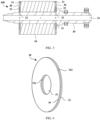
- a structure of a motor that uses an oil cooling heat dissipation technology and that is shown in FIG. 1 includes a rotor iron core 01 and a rotor shaft 02 that is securely fitted in the rotor iron core 01.
- fastening plates 03 are further separately disposed at two ends of the rotor iron core 01, and through holes allowing the rotor shaft to pass through are disposed in the fastening plates 03.
- a blind hole 04 is disposed on an end face of the rotor shaft 02 along an axial direction, and a through hole 05 extending from the blind hole 04 to a surface of a circumferential side of the rotor shaft 02 is disposed along a radial direction in the rotor shaft 02;
- a first groove 06 communicating with the through hole 05 is disposed on an inner wall of the rotor iron core 01, and the first groove 06 is disposed along an axial direction of the rotor iron core 01 and leads to the fastening plates 03 at the two ends;
- a second groove 07 is disposed in the fastening plate 03 along a radial direction of the fastening plate 03, one end of the second groove 07 communicates with the first groove 06, and the other end of the second groove 07 leads to a surface of a circumferential side of the fastening plate 03.
- coolant oil flows into the blind hole 04 from an orifice of the blind hole 04, and then flows into the first groove 06 after flowing through the through hole 05, to dissipate heat for the inner wall of the rotor iron core 01.
- the coolant oil flows into the second groove 07 from the first groove 06, and because being pushed by a centrifugal force generated when the rotor rotates, flows to the end that is of the second groove 07 and that is close to the surface of the circumferential side of the fastening plate 03 from the end that is of the second groove 07 and that is close to the first groove 06, to dissipate heat for an end portion of the rotor iron core 01.
- a defect of the oil cooling heat dissipation technology is as follows: Provided that the motor is in an operating state, the coolant oil always flows in the cooling passage including the blind hole 04, the through hole 05, the first groove 06, and the second groove 07, and sprays from the surface of the circumferential side of the fastening plate 03.
- the motor operates at a low speed, a core loss of the rotor is comparatively low, and an amount of generated heat is comparatively small. In this case, there is no need to perform heat dissipation for the end portion of the rotor iron core 01.
- an embodiment of this application provides a rotor. For a motor using the rotor, a kinetic energy loss of the motor can be reduced while implementing effective heat dissipation for the rotor.
- the rotor 100 includes a rotor iron core 10 and a rotor shaft 20.
- the rotor iron core 10 is cylindrical in shape. Along an axial direction of the rotor iron core 10, the rotor iron core 10 includes a first end 11 and a second end 12 whose positions are opposite.
- the rotor shaft 20 is securely fitted in a cylindrical cavity of the rotor iron core 10, and two ends of the rotor shaft 20 separately extend to the outside of the rotor iron core 10 from the first end 11 and the second end 12.
- the rotor shaft 20 may be specifically interference-fitted in the rotor iron core 10 in a press-fitting manner, to ensure reliability of fitting between the rotor shaft 20 and the rotor iron core 10.
- the rotor iron core 10 is formed by punching and laminating silicon steel sheets.
- a fastening plate 30 configured to fasten the silicon steel sheets is disposed at least one end of the rotor iron core 10.
- the fastening plate 30 may be further used to correct dynamic balance of the rotor when the rotor rotates, to enable the rotor to rotate more safely and stably.
- a diameter of the fastening plate 30 may be not greater than a diameter of the rotor iron core 10.
- the diameter of the fastening plate 30 may be designed to be slightly less than the diameter of the rotor iron core 10, or designed to be equal to the diameter of the rotor iron core 10, to facilitate subsequent assembly of the entire motor.
- a through hole 31 is disposed in the fastening plate 30, to enable at least one end of the rotor shaft 20 to extend to the outside of the rotor iron core 10 through the corresponding through hole 31.
- the fastening plates 30 may be separately fastened to the first end 11 and the second end 12 of the rotor iron core 10.
- a cooling passage configured for heat dissipation is disposed in the rotor 100.
- a first runner 32 is disposed in the fastening plate 30, an inlet 321 of the first runner communicates with the through hole 31 of the fastening plate 30, and an outlet 322 of the first runner is disposed on a surface of a circumferential side of the fastening plate 30.
- the first runner 32 may be disposed on an end face on which the fastening plate 30 fits with the end portion of the rotor iron core. In this case, the first runner 32 is actually a groove-shaped runner.
- the groove-shaped runner can be sealed by the first end or the second end of the rotor iron core.
- the first runner 32 may be alternatively disposed inside the fastening plate 30, that is, disposed between two end faces of the fastening plate 30.
- the first runner 32 is a hole-shaped runner.
- the fastening plate 30 may be designed as a laminated structure formed by stacking a first sub-plate 33 and a second sub-plate 34.
- a groove 323 is disposed on each of an end face that is of the first sub-plate 33 and that faces the second sub-plate 34 and an end face that is of the second sub-plate 34 and that faces the first sub-plate 33.
- the first runner 32 is formed after the first sub-plate 33 and the second sub-plate 34 are stacked with positions of the two grooves 323 opposite to each other.
- a second runner 21 is disposed in the rotor shaft 20, the second runner 21 is disposed along an axial direction of the rotor shaft 20, and an inlet of the second runner 21 is disposed at one end of the rotor shaft 20.
- a third runner 22 is disposed in the rotor shaft 20 at least at one of positions corresponding to the through hole 31.
- the third runner 22 is disposed along a radial direction of the rotor shaft 20, and is configured to enable the second runner 21 to communicate with the first runner 32. In this way, the second runner 21, the third runner 22, and the first runner 32 communicate sequentially, thereby forming the cooling passage of the rotor 100.
- coolant oil flows into the second runner 21 from the inlet of the second runner 21, then enters the first runner 32 after flowing through the third runner 22, and in the first runner 32, tends to flow from the inlet 321 of the first runner to the outlet 322 of the first runner because being pushed by a centrifugal force generated when the rotor 100 rotates.
- the first runner 32 may be designed as a damping runner. In this way, when the rotor rotates at a low speed, the centrifugal force acting on the coolant oil is comparatively small, and a damping characteristic of the first runner 32 can prevent a flowing tendency of the coolant oil caused by the centrifugal force, and prevent the coolant oil from flowing in the first runner 32 and spraying, thereby reducing a kinetic energy loss of the motor.
- the centrifugal force acting on the coolant oil is comparatively large, and therefore, the coolant oil can overcome a flowing resistance in the first runner 32, and flow in the first runner 32 and spray from the outlet of the first runner 32, thereby dissipating heat for the end portion of the rotor iron core.
- the first runner 32 is designed as the damping runner. This can not only reduce a kinetic energy loss occurring when the rotor 100 rotates at a low speed, but also ensure effective heat dissipation for the rotor 100 rotating at a high speed, thereby further increasing a maximum rotational speed of the motor and prolonging duration of a peak power at a high rotational speed.
- high-speed rotation or low-speed rotation of the rotor 100 herein is relative.
- a critical rotational speed may be set based on heat generation of the rotor 100 during rotation.
- an amount of heat generated by the rotor 100 is comparatively small, and in this case, heat dissipation may not be performed for the end portion of the rotor iron core 10.
- a rotational speed of the rotor 100 is higher than the critical rotational speed, an amount of heat generated by the rotor 100 is comparatively large, and in this case, heat dissipation needs to be performed for the end portion of the rotor iron core 10.
- a flowing resistance in the first runner 32 can be designed based on the centrifugal force acting on the coolant oil when the rotor 100 rotates at the critical rotational speed.
- the first runner may be designed as a slender hole.
- a damping effect of the slender hole is used for increasing a flowing resistance when the coolant oil flows.
- a length-to-diameter ratio of the slender hole may be specifically designed based on the centrifugal force acting on the coolant oil when the rotor rotates at a low speed.
- a specific value of the length-to-diameter ratio is not limited in this application, provided that a flowing resistance generated by the slender hole can prevent the coolant oil from flowing in the first runner when the rotor is in a low-speed rotation state, and can be overcome by the centrifugal force acting on the coolant oil when the rotor is in a high-speed rotation state.
- the first runner may be alternatively designed as a bent runner.
- a damping effect generated by the bent runner is used to increase a flowing resistance when the coolant oil flows.
- a quantity of bent sections of the bent runner may also be designed based on the centrifugal force acting on the coolant oil when the rotor rotates at a low speed. This is not limited in this application.
- the first runner 32 may be alternatively designed as a bent slender hole, to further ensure a damping effect of the first runner 32 when the rotor rotates at a low speed.
- first runners 32 There may be specifically two or more first runners 32, and during disposing, the two or more first runners 32 are evenly distributed in the fastening plate 30. In this way, not only a heat dissipation effect and heat dissipation uniformity can be improved for the end portion of the rotor iron core, but also a position of a center of gravity of the fastening plate 30 can always be maintained near a center of the fastening plate 30, which helps the rotor rotate stably.
- one outlet 322 may be disposed, or a plurality of outlets 322 may be disposed for each first runner 32. For example, as shown in FIG.
- two outlets 322 are disposed for each first runner 32 on the surface of the circumferential side of the fastening plate 30. This can further increase a coverage area of the first runner 32, and improve a heat dissipation effect for the end portion of the rotor iron core.
- first runners 32 there are a plurality of first runners 32, correspondingly, as shown in FIG. 2 , there are also a plurality of third runners 22 that are configured to enable the first runners 32 and the second runner 21 to communicate.
- the third runners 22 may also be evenly distributed in the rotor shaft 20 along a principal axis of the rotor shaft 20, to ensure stability of the rotor 100 during rotation.
- an inner wall of a rotor iron core 10 has a fourth runner 13.
- the fourth runner 13 is disposed along the axial direction of the rotor iron core 10 and extends from a first end 11 of the rotor iron core 10 to a second end 12 of the rotor iron core 10.
- An inlet of the fourth runner 13 communicates with a first runner 32 in a fastening plate 30 fastened to the first end 11, and an outlet of the fourth runner 13 communicates with a first runner 32 in a fastening plate 30 fastened to the second end 12.
- a groove 35 may be disposed on a sub-plate that is of the fastening plate 30 and that is close to the rotor iron core 10, one end of the groove 35 is made to communicate with the first runner 32, and the other end of the groove 35 is made to communicate with the fourth runner 13.
- coolant oil flows into a second runner 21 from an inlet of the second runner 21, and then flows through a third runner 22 and enters the first runner 32 in the fastening plate 30.
- a portion of the coolant oil flows from the first runner 32 into the fourth runner 13 in which a pressure is comparatively low, and flows to the outlet of the fourth runner 13 from the inlet of the fourth runner 13, thereby dissipating heat for the inner wall on which the rotor iron core 10 and a rotor shaft 20 fit together.
- a plurality of fourth runners 13 may be disposed on the inner wall of the rotor iron core 10. For example, in the embodiment shown in FIG. 7 , there are four fourth runners 13, and the four first runners are evenly distributed on the inner wall of the rotor iron core 10.
- a flowing resistance in the first runner 32 corresponding to the first end 11 may be designed to be greater than a flowing resistance in the first runner 32 corresponding to the second end 12.
- the flowing resistance in the first runner 32 corresponding to the first end 11 may actually be slightly greater than a sum of the flowing resistance in the first runner 32 corresponding to the second end 12 and the flowing resistance in the fourth runner 13.
- the flowing resistances in the first runners 32 in the two fastening plates 30 may be controlled by enabling the first runners 32 to use different length-to-diameter ratios.
- the first runner 32 in the fastening plate 30 fastened to the first end 11 has a first length-to-diameter ratio
- the first runner 32 in the fastening plate 30 fastened to the second end 12 has a second length-to-diameter ratio.
- the flowing resistance in the first runner 32 in the fastening plate 30 fastened to the first end 11 can be made greater than the flowing resistance in the first runner 32 in the other fastening plate 30.
- the first length-to-diameter ratio and the second length-to-diameter ratio may be specifically set based on actual application. This is not limited in this application.
- the flowing resistances in the first runners 32 in the two fastening plates 30 may be alternatively controlled by enabling the first runners 32 to have different quantities of bent sections.
- the first runner 32 in the fastening plate 30 fastened to the first end 11 has m bent sections
- the first runner 32 in the fastening plate 30 fastened to the second end 12 has n bent sections.
- m > n the flowing resistance in the first runner 32 in the fastening plate 30 fastened to the first end 11 can be made greater than the flowing resistance in the first runner 32 in the other fastening plate 30.
- Both m and n are positive integers, and specific values of m and n may be specifically set based on actual application.
- the third runner 22 is disposed in the rotor shaft 20 only at a position corresponding to the fastening plate 30 fastened to the first end 11, and no third runner 22 is disposed at a position corresponding to the fastening plate 30 fastened to the second end 12.
- a flowing path of the coolant oil is as follows: The coolant oil flows into the second runner 21 from the inlet of the second runner 21, and then flows through the third runner 22 and enters the first runner 32 in the fastening plate 30 fastened to the first end 11.
- One portion of the coolant oil entering the first runner 32 flows to an outlet of the first runner from an inlet of the first runner as the rotor 100 rotates, to dissipate heat for the first end 11 of the rotor iron core 10.
- Another portion of the coolant oil entering the first runner 32 flows into the fourth runner 13, flows to the outlet of the fourth runner 13 from the inlet of the fourth runner 13, to dissipate heat for the inner wall on which the rotor iron core 10 and the rotor shaft 20 fit together, then flows into the first runner 32 in the fastening plate 30 fastened to the second end 12 from the outlet of the fourth runner 13, and flows to an outlet of the first runner 32 from an inlet of the first runner 32 as the rotor 100 rotates, to dissipate heat for the second end 12 of the rotor iron core 10.
- a fifth runner 14 is disposed between an inner wall and an outer wall of a rotor iron core 10.
- the fifth runner 14 is also disposed along the axial direction of the rotor iron core 10 and extends from a first end 11 of the rotor iron core 10 to a second end 12 of the rotor iron core 10.
- An inlet of the fifth runner 14 communicates with a first runner 32 in a fastening plate 30 fastened to the first end 11, and an outlet of the fifth runner 14 communicates with a first runner 32 in a fastening plate 30 fastened to the second end 12.
- a hole 36 may be disposed on a sub-plate that is of the fastening plate 30 and that is close to the rotor iron core 10, one end of the hole 36 is made to communicate with the first runner 32, and the other end of the hole 36 is made to communicate with the fifth runner 14.
- coolant oil flows into a second runner 21 from an inlet of the second runner 21, and then flows through a third runner 22 and enters the first runner 32 in the fastening plate 30.
- a portion of the coolant oil flows from the first runner 32 into the fifth runner 14 in which a pressure is comparatively low, and flows to the outlet of the fifth runner 14 from the inlet of the fifth runner 14, thereby dissipating heat for an interior of the rotor iron core 10.
- a plurality of fifth runners 14 may be disposed in the rotor iron core 10. During specific disposing, the plurality of fifth runners 14 may be evenly distributed in the rotor iron core, to improve heat dissipation uniformity for the interior of the rotor iron core.
- a flowing resistance in the first runner 32 corresponding to the first end 11 may also be designed to be greater than a flowing resistance in the first runner 32 corresponding to the second end 12.
- the flowing resistance in the first runner 32 corresponding to the first end 11 may actually be slightly greater than a sum of the flowing resistance in the first runner 32 corresponding to the second end 12 and the flowing resistance in the fifth runner 14.
- the flowing resistances in the first runners 32 in the two fastening plates 30 may be controlled by enabling the first runners 32 to use different length-to-diameter ratios or have different quantities of bent sections. Details are not described herein again.
- the third runner 22 may also be disposed in a rotor shaft 20 only at a position corresponding to the fastening plate 30 fastened to the first end 11, and no third runner 22 is disposed at a position corresponding to the fastening plate 30 fastened to the second end 12.
- a flowing path of the coolant oil is as follows: The coolant oil flows into the second runner 21 from the inlet of the second runner 21, and then flows through the third runner 22 and enters the first runner 32 in the fastening plate 30 fastened to the first end 11.
- One portion of the coolant oil entering the first runner 32 flows to an outlet of the first runner 32 from an inlet of the first runner 32 as the rotor 100 rotates, to dissipate heat for the first end 11 of the rotor iron core 10.
- Another portion of the coolant oil entering the first runner 32 flows into the fifth runner 14, flows to the outlet of the fifth runner 14 from the inlet of the fifth runner 14, to dissipate heat for the interior of the rotor iron core 10, then flows into the first runner 32 in the fastening plate 30 fastened to the second end 12 from the outlet of the fifth runner 14, and flows to an outlet of the first runner 32 from an inlet of the first runner 32 as the rotor 100 rotates, to dissipate heat for the second end 12 of the rotor iron core 10.
- the first runner is designed as the damping runner. This can not only reduce a kinetic energy loss occurring when the rotor rotates at a low speed, but also ensure effective heat dissipation for the rotor rotating at a high speed, thereby further increasing a maximum rotational speed and prolonging duration of a peak power at a high rotational speed.
- An embodiment of this application further provides a motor 1.
- the motor may be specifically applied to an electric vehicle, and serve as a power system of the electric vehicle to provide a driving force for driving of the electric vehicle.
- the motor 1 includes a stator 200 and the rotor 100 provided in any one of the foregoing embodiments.
- the stator 200 includes a stator iron core 40 and a stator coil 50.
- the stator iron core 40 is cylindrical in shape, and there are a plurality of tooth portions disposed on an inner wall of the stator iron core 40 along an axial direction of the stator iron core 40.
- the stator coil 50 is disposed by winding around these tooth portions, and the stator coil 50 has coil end portions 51 protruding from two ends of the stator iron core 40.
- the rotor 100 is rotatably fitted in the stator iron core 40.
- the two fastening plates 30 fastened to the two ends of the rotor iron core 10 separately extend beyond the two ends of the stator iron core 40, so that the outlets that are of the first runners 32 and that are disposed on the surfaces of the circumferential sides of the fastening plates 30 can be disposed toward the coil end portions 51.
- the motor 1 further includes a housing 300 configured to accommodate the stator 200 and the rotor 100, and the stator iron core is interference-fitted in the housing 300, so that the stator 200 and the rotor 100 can maintain fastened between each other.
- the motor may further include a circulation pump and an oil storage tank.
- an oil return port communicating with the oil storage tank may be disposed on the housing.
- An oil inlet port of the circulation pump communicates with the oil storage tank, and an oil outlet port of the circulation pump communicates with the inlet of the second runner in the rotor shaft.
- the coolant oil sprays from the outlet of the first runner to continue to dissipate heat for the coil end portion of the stator, and then collects in the housing and flows to the oil storage tank from the oil return port, to implement recycling.
- an embodiment of this application further provides an electric vehicle.
- the electric vehicle includes the motor 1 in the foregoing embodiment, and further includes a transmission device 2 and driving wheels 3.
- the motor 1 is in transmission connection with the transmission device 2, and the transmission device 2 is then in transmission connection with the driving wheels 3, so that a driving force output by the motor 1 can be transferred to the driving wheels 3 through the transmission device 2, to drive the electric vehicle to run.
- a heat dissipation effect of the motor 1 is comparatively good, and a kinetic energy loss is reduced accordingly, power performance of the electric vehicle can be effectively improved.
Landscapes
- Engineering & Computer Science (AREA)
- Power Engineering (AREA)
- Chemical & Material Sciences (AREA)
- Combustion & Propulsion (AREA)
- Transportation (AREA)
- Mechanical Engineering (AREA)
- Motor Or Generator Cooling System (AREA)
- Iron Core Of Rotating Electric Machines (AREA)
Description
- This application claims priority to
Chinese Patent Application No. 201910570394.7, filed with the Chinese Patent Office on June 27, 2019 - This application relates to the field of mechanical equipment technologies, and in particular, to a rotor, a motor, and an electric vehicle.
- In the conventional technology, motors mostly use a water cooling heat dissipation technology for heat dissipation. However, a power density of water cooling heat dissipation is comparatively low, and cooling water cannot be in direct contact with motor components because the cooling water does not have an insulation property, resulting in a comparatively high link thermal resistance of a cooling passage and a poor heat dissipation effect. In addition, the water cooling heat dissipation technology has a comparatively high requirement for structural precision of the motor components. Consequently, both manufacturing costs and time costs of the motors increase accordingly. To overcome the foregoing problems, some motors currently begin to use oil cooling heat dissipation to replace water cooling heat dissipation. For an existing motor using an oil cooling heat dissipation technology, at an end portion of a rotor of the motor, a cooling passage configured for dissipating heat for the end portion is disposed. Coolant oil flows in the cooling passage as the rotor rotates, and finally sprays from the cooling passage when being pushed by a centrifugal force generated when the rotor rotates, to implement heat dissipation. However, when the motor operates at a low speed, a core loss of the rotor is comparatively low, and a limited amount of heat is generated. Therefore, there is no need to perform heat dissipation for the rotor. In this case, if the rotor still drives the coolant oil to flow and causes the coolant oil to spray when the rotor rotates, part of kinetic energy of the motor is lost.
-
US 2012/025642 A1 discloses a rotating electric machine that can be improved in cooling performance. An end plate includes an annular plate portion arranged to be spaced from a rotor in an axial direction and secured to a rotation shaft, and a tubular portion protruding from an outer edge of the annular plate portion to abut on an axial end surface of the rotor. A partition plate arranged between the rotor and an end plate forms a first space between the rotor and the partition plate and a second space between the annular plate portion and the partition plate. A communication passage allowing the first space and the second space to communicate with each other is formed in the partition plate at a radially outer side relative to a permanent magnet. A through hole extending through the annular plate portion in the axial direction is formed in the annular plate portion at a radially inner side relative to the permanent magnet. -
US 2016/322876 A1 discloses winding bodies that are produced by repeatedly winding a δ-shaped coil pattern that is formed by inserting the conductor wire sequentially into a second slot, a first slot, a second slot, and a third slot, so as to alternate an axial direction of insertion into the first slot, the second slot, and the third slot, for two turns in a radial direction, and are configured such that a plurality of rectilinear portions that are respectively inserted into the first slot, the second slot, and the third slot are linked continuously by coil end portions, and a liquid coolant is supplied to a coil end that is constituted by the coil end portions. -
JP 2011 254574 A - This application provides a rotor, a motor, and an electric vehicle, to reduce a kinetic energy loss of the motor while implementing effective heat dissipation for the rotor.
- This application provides a rotor as claimed in
claim 1. -
-
FIG. 1 is a schematic structural diagram of a rotor in the conventional technology; -
FIG. 2 is a schematic diagram of a partial structure of a rotor according to an example helpful for understanding the invention but not covered by the claims; -
FIG. 3 is a cutaway view of the rotor according to the example; -
FIG. 4 is a schematic structural diagram of a fastening plate according to the example; -
FIG. 5 is a cutaway view of the fastening plate according to the example; -
FIG. 6 is a cutaway view of a rotor according to an embodiment of this application; -
FIG. 7 is a cutaway view of an axial side of the rotor according to the another embodiment of this application; -
FIG. 8 is a cutaway view of a rotor according to still another embodiment of this application; -
FIG. 9 is a schematic diagram of a partial structure of the rotor according to the still another embodiment of this application; -
FIG. 10 is a cutaway view of a rotor according to an example helpful for understanding the invention but not covered by the claims; -
FIG. 11 is a cutaway view of a motor according to an example helpful for understanding the invention but not covered by the claims; -
FIG. 12 is a schematic diagram of a partial structure of the motor according to the example; and -
FIG. 13 is a schematic structural diagram of an electric vehicle according to an embodiment of this application. - To make the objectives, technical solutions, and advantages of this application clearer, the following further describes this application in detail with reference to the accompanying drawings.
- To resolve problems occurring when a water cooling heat dissipation technology is used, such as a poor heat dissipation effect and a high requirement for structural precision, currently, some motors gradually use oil cooling heat dissipation to replace water cooling heat dissipation. A structure of a motor that uses an oil cooling heat dissipation technology and that is shown in
FIG. 1 includes arotor iron core 01 and arotor shaft 02 that is securely fitted in therotor iron core 01. In addition,fastening plates 03 are further separately disposed at two ends of therotor iron core 01, and through holes allowing the rotor shaft to pass through are disposed in thefastening plates 03. When a cooling passage is arranged, ablind hole 04 is disposed on an end face of therotor shaft 02 along an axial direction, and a throughhole 05 extending from theblind hole 04 to a surface of a circumferential side of therotor shaft 02 is disposed along a radial direction in therotor shaft 02; afirst groove 06 communicating with the throughhole 05 is disposed on an inner wall of therotor iron core 01, and thefirst groove 06 is disposed along an axial direction of therotor iron core 01 and leads to thefastening plates 03 at the two ends; and asecond groove 07 is disposed in thefastening plate 03 along a radial direction of thefastening plate 03, one end of thesecond groove 07 communicates with thefirst groove 06, and the other end of thesecond groove 07 leads to a surface of a circumferential side of thefastening plate 03. In this way, coolant oil flows into theblind hole 04 from an orifice of theblind hole 04, and then flows into thefirst groove 06 after flowing through the throughhole 05, to dissipate heat for the inner wall of therotor iron core 01. Then, the coolant oil flows into thesecond groove 07 from thefirst groove 06, and because being pushed by a centrifugal force generated when the rotor rotates, flows to the end that is of thesecond groove 07 and that is close to the surface of the circumferential side of thefastening plate 03 from the end that is of thesecond groove 07 and that is close to thefirst groove 06, to dissipate heat for an end portion of therotor iron core 01. Finally, the coolant oil sprays from the surface of the circumferential side of thefastening plate 03. A defect of the oil cooling heat dissipation technology is as follows: Provided that the motor is in an operating state, the coolant oil always flows in the cooling passage including theblind hole 04, the throughhole 05, thefirst groove 06, and thesecond groove 07, and sprays from the surface of the circumferential side of thefastening plate 03. However, when the motor operates at a low speed, a core loss of the rotor is comparatively low, and an amount of generated heat is comparatively small. In this case, there is no need to perform heat dissipation for the end portion of therotor iron core 01. If the rotor continues to drive the coolant oil to flow and causes the coolant oil to spray, part of kinetic energy of the motor is lost. Based on this, an embodiment of this application provides a rotor. For a motor using the rotor, a kinetic energy loss of the motor can be reduced while implementing effective heat dissipation for the rotor. - First, as shown in
FIG. 2 andFIG. 3 , therotor 100 includes arotor iron core 10 and arotor shaft 20. Therotor iron core 10 is cylindrical in shape. Along an axial direction of therotor iron core 10, therotor iron core 10 includes afirst end 11 and asecond end 12 whose positions are opposite. Therotor shaft 20 is securely fitted in a cylindrical cavity of therotor iron core 10, and two ends of therotor shaft 20 separately extend to the outside of therotor iron core 10 from thefirst end 11 and thesecond end 12. During specific disposing, therotor shaft 20 may be specifically interference-fitted in therotor iron core 10 in a press-fitting manner, to ensure reliability of fitting between therotor shaft 20 and therotor iron core 10. - The
rotor iron core 10 is formed by punching and laminating silicon steel sheets. To improve structural stability of therotor iron core 10, afastening plate 30 configured to fasten the silicon steel sheets is disposed at least one end of therotor iron core 10. In addition, thefastening plate 30 may be further used to correct dynamic balance of the rotor when the rotor rotates, to enable the rotor to rotate more safely and stably. During specific disposing, a diameter of thefastening plate 30 may be not greater than a diameter of therotor iron core 10. For example, the diameter of thefastening plate 30 may be designed to be slightly less than the diameter of therotor iron core 10, or designed to be equal to the diameter of therotor iron core 10, to facilitate subsequent assembly of the entire motor. As shown inFIG. 3 , a throughhole 31 is disposed in thefastening plate 30, to enable at least one end of therotor shaft 20 to extend to the outside of therotor iron core 10 through the corresponding throughhole 31. Certainly, to further improve structural stability of therotor iron core 10 and improve a heat dissipation effect for end portions of therotor iron core 10, in this embodiment of this application, thefastening plates 30 may be separately fastened to thefirst end 11 and thesecond end 12 of therotor iron core 10. - In this example, a cooling passage configured for heat dissipation is disposed in the
rotor 100. When the cooling passage is specifically arranged, as shown inFIG. 4 andFIG. 5 , afirst runner 32 is disposed in thefastening plate 30, aninlet 321 of the first runner communicates with the throughhole 31 of thefastening plate 30, and anoutlet 322 of the first runner is disposed on a surface of a circumferential side of thefastening plate 30. When being disposed, thefirst runner 32 may be disposed on an end face on which thefastening plate 30 fits with the end portion of the rotor iron core. In this case, thefirst runner 32 is actually a groove-shaped runner. When thefastening plate 30 is fastened to and pressed against the first end or the second end of the rotor iron core, the groove-shaped runner can be sealed by the first end or the second end of the rotor iron core. Certainly, thefirst runner 32 may be alternatively disposed inside thefastening plate 30, that is, disposed between two end faces of thefastening plate 30. In this case, thefirst runner 32 is a hole-shaped runner. It should be noted that when thefirst runner 32 is a hole-shaped runner, to facilitate processing, thefastening plate 30 may be designed as a laminated structure formed by stacking afirst sub-plate 33 and asecond sub-plate 34. Then, agroove 323 is disposed on each of an end face that is of thefirst sub-plate 33 and that faces thesecond sub-plate 34 and an end face that is of thesecond sub-plate 34 and that faces thefirst sub-plate 33. Thefirst runner 32 is formed after thefirst sub-plate 33 and the second sub-plate 34 are stacked with positions of the twogrooves 323 opposite to each other. As shown inFIG. 2 andFIG. 3 , asecond runner 21 is disposed in therotor shaft 20, thesecond runner 21 is disposed along an axial direction of therotor shaft 20, and an inlet of thesecond runner 21 is disposed at one end of therotor shaft 20. In addition, athird runner 22 is disposed in therotor shaft 20 at least at one of positions corresponding to the throughhole 31. Thethird runner 22 is disposed along a radial direction of therotor shaft 20, and is configured to enable thesecond runner 21 to communicate with thefirst runner 32. In this way, thesecond runner 21, thethird runner 22, and thefirst runner 32 communicate sequentially, thereby forming the cooling passage of therotor 100. - When heat dissipation is performed for the
rotor 100 by using the cooling passage, as shown inFIG. 2 andFIG. 3 , coolant oil flows into thesecond runner 21 from the inlet of thesecond runner 21, then enters thefirst runner 32 after flowing through thethird runner 22, and in thefirst runner 32, tends to flow from theinlet 321 of the first runner to theoutlet 322 of the first runner because being pushed by a centrifugal force generated when therotor 100 rotates. When the coolant oil arrives at theoutlet 322 of the first runner from theinlet 321 of the first runner and sprays from the outlet, heat at the end portion of therotor iron core 10 can be taken away through direct or indirect contact with the end portion of therotor iron core 10, thereby dissipating heat for the end portion of therotor iron core 10. - When the motor operates at a low speed, a core loss of the
rotor 100 is comparatively low, and an amount of generated heat is comparatively small. In this case, there is no need to perform proactive heat dissipation for the end portion of therotor iron core 10. Therefore, in this embodiment of this application, thefirst runner 32 may be designed as a damping runner. In this way, when the rotor rotates at a low speed, the centrifugal force acting on the coolant oil is comparatively small, and a damping characteristic of thefirst runner 32 can prevent a flowing tendency of the coolant oil caused by the centrifugal force, and prevent the coolant oil from flowing in thefirst runner 32 and spraying, thereby reducing a kinetic energy loss of the motor. When therotor 100 rotates at a high speed, the centrifugal force acting on the coolant oil is comparatively large, and therefore, the coolant oil can overcome a flowing resistance in thefirst runner 32, and flow in thefirst runner 32 and spray from the outlet of thefirst runner 32, thereby dissipating heat for the end portion of the rotor iron core. In other words, thefirst runner 32 is designed as the damping runner. This can not only reduce a kinetic energy loss occurring when therotor 100 rotates at a low speed, but also ensure effective heat dissipation for therotor 100 rotating at a high speed, thereby further increasing a maximum rotational speed of the motor and prolonging duration of a peak power at a high rotational speed. It should be noted that high-speed rotation or low-speed rotation of therotor 100 herein is relative. In actual application, a critical rotational speed may be set based on heat generation of therotor 100 during rotation. When a rotational speed of therotor 100 is lower than the critical rotational speed, an amount of heat generated by therotor 100 is comparatively small, and in this case, heat dissipation may not be performed for the end portion of therotor iron core 10. When a rotational speed of therotor 100 is higher than the critical rotational speed, an amount of heat generated by therotor 100 is comparatively large, and in this case, heat dissipation needs to be performed for the end portion of therotor iron core 10. In this way, a flowing resistance in thefirst runner 32 can be designed based on the centrifugal force acting on the coolant oil when therotor 100 rotates at the critical rotational speed. - During specific disposing, in an embodiment of this application, the first runner may be designed as a slender hole. A damping effect of the slender hole is used for increasing a flowing resistance when the coolant oil flows. It should be noted that a length-to-diameter ratio of the slender hole may be specifically designed based on the centrifugal force acting on the coolant oil when the rotor rotates at a low speed. A specific value of the length-to-diameter ratio is not limited in this application, provided that a flowing resistance generated by the slender hole can prevent the coolant oil from flowing in the first runner when the rotor is in a low-speed rotation state, and can be overcome by the centrifugal force acting on the coolant oil when the rotor is in a high-speed rotation state.
- The first runner may be alternatively designed as a bent runner. A damping effect generated by the bent runner is used to increase a flowing resistance when the coolant oil flows. Likewise, a quantity of bent sections of the bent runner may also be designed based on the centrifugal force acting on the coolant oil when the rotor rotates at a low speed. This is not limited in this application.
- Certainly, as shown in
FIG. 5 , thefirst runner 32 may be alternatively designed as a bent slender hole, to further ensure a damping effect of thefirst runner 32 when the rotor rotates at a low speed. - There may be specifically two or more
first runners 32, and during disposing, the two or morefirst runners 32 are evenly distributed in thefastening plate 30. In this way, not only a heat dissipation effect and heat dissipation uniformity can be improved for the end portion of the rotor iron core, but also a position of a center of gravity of thefastening plate 30 can always be maintained near a center of thefastening plate 30, which helps the rotor rotate stably. Corresponding to theinlet 321 ofeachfirst runner 32, oneoutlet 322 may be disposed, or a plurality ofoutlets 322 may be disposed for eachfirst runner 32. For example, as shown inFIG. 5 , twooutlets 322 are disposed for eachfirst runner 32 on the surface of the circumferential side of thefastening plate 30. This can further increase a coverage area of thefirst runner 32, and improve a heat dissipation effect for the end portion of the rotor iron core. - It should be noted that when there are a plurality of
first runners 32, correspondingly, as shown inFIG. 2 , there are also a plurality ofthird runners 22 that are configured to enable thefirst runners 32 and thesecond runner 21 to communicate. In this case, thethird runners 22 may also be evenly distributed in therotor shaft 20 along a principal axis of therotor shaft 20, to ensure stability of therotor 100 during rotation. - In accordance with an embodiment of the invention, as shown in
FIG. 6 andFIG. 7 , an inner wall of arotor iron core 10 has afourth runner 13. Thefourth runner 13 is disposed along the axial direction of therotor iron core 10 and extends from afirst end 11 of therotor iron core 10 to asecond end 12 of therotor iron core 10. An inlet of thefourth runner 13 communicates with afirst runner 32 in afastening plate 30 fastened to thefirst end 11, and an outlet of thefourth runner 13 communicates with afirst runner 32 in afastening plate 30 fastened to thesecond end 12. It should be noted that in a case in which thefastening plate 30 is a laminated structure, when thefourth runner 13 is made to communicate with thefirst runners 32 in thefastening plates 30 on two sides, for eachfastening plate 30, agroove 35 may be disposed on a sub-plate that is of thefastening plate 30 and that is close to therotor iron core 10, one end of thegroove 35 is made to communicate with thefirst runner 32, and the other end of thegroove 35 is made to communicate with thefourth runner 13. In this embodiment, coolant oil flows into asecond runner 21 from an inlet of thesecond runner 21, and then flows through athird runner 22 and enters thefirst runner 32 in thefastening plate 30. Further, when arotor 100 rotates, due to a pressure difference, a portion of the coolant oil flows from thefirst runner 32 into thefourth runner 13 in which a pressure is comparatively low, and flows to the outlet of thefourth runner 13 from the inlet of thefourth runner 13, thereby dissipating heat for the inner wall on which therotor iron core 10 and arotor shaft 20 fit together. In addition, to improve a heat dissipation effect, a plurality offourth runners 13 may be disposed on the inner wall of therotor iron core 10. For example, in the embodiment shown inFIG. 7 , there are fourfourth runners 13, and the four first runners are evenly distributed on the inner wall of therotor iron core 10. - To enable the coolant oil in the
fourth runner 13 to flow from the outlet of thefourth runner 13 into thefirst runner 32 in thefastening plate 30 fastened to thesecond end 12, a flowing resistance in thefirst runner 32 corresponding to thefirst end 11 may be designed to be greater than a flowing resistance in thefirst runner 32 corresponding to thesecond end 12. Certainly, considering that there is also a specific flowing resistance in thefourth runner 13, to ensure a cooling effect, the flowing resistance in thefirst runner 32 corresponding to thefirst end 11 may actually be slightly greater than a sum of the flowing resistance in thefirst runner 32 corresponding to thesecond end 12 and the flowing resistance in thefourth runner 13. - During specific disposing, in a specific embodiment of this application, the flowing resistances in the
first runners 32 in the twofastening plates 30 may be controlled by enabling thefirst runners 32 to use different length-to-diameter ratios. For example, thefirst runner 32 in thefastening plate 30 fastened to thefirst end 11 has a first length-to-diameter ratio, and thefirst runner 32 in thefastening plate 30 fastened to thesecond end 12 has a second length-to-diameter ratio. When the first length-to-diameter ratio is greater than the second length-to-diameter ratio, the flowing resistance in thefirst runner 32 in thefastening plate 30 fastened to thefirst end 11 can be made greater than the flowing resistance in thefirst runner 32 in theother fastening plate 30. The first length-to-diameter ratio and the second length-to-diameter ratio may be specifically set based on actual application. This is not limited in this application. - In another specific embodiment of this application, the flowing resistances in the
first runners 32 in the twofastening plates 30 may be alternatively controlled by enabling thefirst runners 32 to have different quantities of bent sections. For example, thefirst runner 32 in thefastening plate 30 fastened to thefirst end 11 has m bent sections, and thefirst runner 32 in thefastening plate 30 fastened to thesecond end 12 has n bent sections. When m > n, the flowing resistance in thefirst runner 32 in thefastening plate 30 fastened to thefirst end 11 can be made greater than the flowing resistance in thefirst runner 32 in theother fastening plate 30. Both m and n are positive integers, and specific values of m and n may be specifically set based on actual application. - It may be understood that to further promote flowing of the coolant oil in the
fourth runner 13, in this embodiment of this application, thethird runner 22 is disposed in therotor shaft 20 only at a position corresponding to thefastening plate 30 fastened to thefirst end 11, and nothird runner 22 is disposed at a position corresponding to thefastening plate 30 fastened to thesecond end 12. In this case, a flowing path of the coolant oil is as follows: The coolant oil flows into thesecond runner 21 from the inlet of thesecond runner 21, and then flows through thethird runner 22 and enters thefirst runner 32 in thefastening plate 30 fastened to thefirst end 11. One portion of the coolant oil entering thefirst runner 32 flows to an outlet of the first runner from an inlet of the first runner as therotor 100 rotates, to dissipate heat for thefirst end 11 of therotor iron core 10. Another portion of the coolant oil entering thefirst runner 32 flows into thefourth runner 13, flows to the outlet of thefourth runner 13 from the inlet of thefourth runner 13, to dissipate heat for the inner wall on which therotor iron core 10 and therotor shaft 20 fit together, then flows into thefirst runner 32 in thefastening plate 30 fastened to thesecond end 12 from the outlet of thefourth runner 13, and flows to an outlet of thefirst runner 32 from an inlet of thefirst runner 32 as therotor 100 rotates, to dissipate heat for thesecond end 12 of therotor iron core 10. - In accordance with another embodiment of the invention, as shown in
FIG. 8 andFIG. 9 , afifth runner 14 is disposed between an inner wall and an outer wall of arotor iron core 10. Thefifth runner 14 is also disposed along the axial direction of therotor iron core 10 and extends from afirst end 11 of therotor iron core 10 to asecond end 12 of therotor iron core 10. An inlet of thefifth runner 14 communicates with afirst runner 32 in afastening plate 30 fastened to thefirst end 11, and an outlet of thefifth runner 14 communicates with afirst runner 32 in afastening plate 30 fastened to thesecond end 12. Likewise, in a case in which thefastening plate 30 is a laminated structure, when thefifth runner 14 is made to communicate with thefirst runners 32 in thefastening plates 30 on two sides, for eachfastening plate 30, ahole 36 may be disposed on a sub-plate that is of thefastening plate 30 and that is close to therotor iron core 10, one end of thehole 36 is made to communicate with thefirst runner 32, and the other end of thehole 36 is made to communicate with thefifth runner 14. In this embodiment, coolant oil flows into asecond runner 21 from an inlet of thesecond runner 21, and then flows through athird runner 22 and enters thefirst runner 32 in thefastening plate 30. Further, when arotor 100 rotates, due to a pressure difference, a portion of the coolant oil flows from thefirst runner 32 into thefifth runner 14 in which a pressure is comparatively low, and flows to the outlet of thefifth runner 14 from the inlet of thefifth runner 14, thereby dissipating heat for an interior of therotor iron core 10. In addition, to improve a heat dissipation effect, a plurality offifth runners 14 may be disposed in therotor iron core 10. During specific disposing, the plurality offifth runners 14 may be evenly distributed in the rotor iron core, to improve heat dissipation uniformity for the interior of the rotor iron core. - Certainly, in the foregoing embodiment, to enable the coolant oil in the
fifth runner 14 to flow from the outlet of thefifth runner 14 into thefirst runner 32 in thefastening plate 30 fastened to thesecond end 12, a flowing resistance in thefirst runner 32 corresponding to thefirst end 11 may also be designed to be greater than a flowing resistance in thefirst runner 32 corresponding to thesecond end 12. Considering that there is also a specific flowing resistance in thefifth runner 14, to ensure a cooling effect, the flowing resistance in thefirst runner 32 corresponding to thefirst end 11 may actually be slightly greater than a sum of the flowing resistance in thefirst runner 32 corresponding to thesecond end 12 and the flowing resistance in thefifth runner 14. During specific disposing, with reference to the foregoing description, the flowing resistances in thefirst runners 32 in the twofastening plates 30 may be controlled by enabling thefirst runners 32 to use different length-to-diameter ratios or have different quantities of bent sections. Details are not described herein again. - In addition, to further promote flowing of the coolant oil in the
fifth runner 14, in this embodiment of this application, thethird runner 22 may also be disposed in arotor shaft 20 only at a position corresponding to thefastening plate 30 fastened to thefirst end 11, and nothird runner 22 is disposed at a position corresponding to thefastening plate 30 fastened to thesecond end 12. In this case, a flowing path of the coolant oil is as follows: The coolant oil flows into thesecond runner 21 from the inlet of thesecond runner 21, and then flows through thethird runner 22 and enters thefirst runner 32 in thefastening plate 30 fastened to thefirst end 11. One portion of the coolant oil entering thefirst runner 32 flows to an outlet of thefirst runner 32 from an inlet of thefirst runner 32 as therotor 100 rotates, to dissipate heat for thefirst end 11 of therotor iron core 10. Another portion of the coolant oil entering thefirst runner 32 flows into thefifth runner 14, flows to the outlet of thefifth runner 14 from the inlet of thefifth runner 14, to dissipate heat for the interior of therotor iron core 10, then flows into thefirst runner 32 in thefastening plate 30 fastened to thesecond end 12 from the outlet of thefifth runner 14, and flows to an outlet of thefirst runner 32 from an inlet of thefirst runner 32 as therotor 100 rotates, to dissipate heat for thesecond end 12 of therotor iron core 10. - In conclusion, in the rotor provided in the embodiments of this application, the first runner is designed as the damping runner. This can not only reduce a kinetic energy loss occurring when the rotor rotates at a low speed, but also ensure effective heat dissipation for the rotor rotating at a high speed, thereby further increasing a maximum rotational speed and prolonging duration of a peak power at a high rotational speed.
- An embodiment of this application further provides a
motor 1. The motor may be specifically applied to an electric vehicle, and serve as a power system of the electric vehicle to provide a driving force for driving of the electric vehicle. As shown inFIG. 11 andFIG. 12 , themotor 1 includes astator 200 and therotor 100 provided in any one of the foregoing embodiments. During specific disposing, thestator 200 includes astator iron core 40 and astator coil 50. Thestator iron core 40 is cylindrical in shape, and there are a plurality of tooth portions disposed on an inner wall of thestator iron core 40 along an axial direction of thestator iron core 40. Thestator coil 50 is disposed by winding around these tooth portions, and thestator coil 50 hascoil end portions 51 protruding from two ends of thestator iron core 40. Therotor 100 is rotatably fitted in thestator iron core 40. As shown inFIG. 10 , the twofastening plates 30 fastened to the two ends of therotor iron core 10 separately extend beyond the two ends of thestator iron core 40, so that the outlets that are of thefirst runners 32 and that are disposed on the surfaces of the circumferential sides of thefastening plates 30 can be disposed toward thecoil end portions 51. In this way, when therotor 100 rotates at a high speed, coolant oil directly sprays toward thecoil end portions 51 after spraying from the outlets of thefirst runners 32, to dissipate heat for thecoil end portions 51. In addition, when the diameter of thefastening plate 30 is close or equal to the diameter of therotor iron core 10, the outlet of thefirst runner 32 is closer to thecoil end 51. In this case, oil can be precisely sprayed to thecoil end portion 51, thereby improving a cooling effect for thecoil end portion 51. - Still as shown in
FIG. 12 , themotor 1 further includes ahousing 300 configured to accommodate thestator 200 and therotor 100, and the stator iron core is interference-fitted in thehousing 300, so that thestator 200 and therotor 100 can maintain fastened between each other. In this embodiment of this application, the motor may further include a circulation pump and an oil storage tank. In addition, an oil return port communicating with the oil storage tank may be disposed on the housing. An oil inlet port of the circulation pump communicates with the oil storage tank, and an oil outlet port of the circulation pump communicates with the inlet of the second runner in the rotor shaft. After entering the cooling passage of the rotor to dissipate heat for corresponding components of the rotor, the coolant oil sprays from the outlet of the first runner to continue to dissipate heat for the coil end portion of the stator, and then collects in the housing and flows to the oil storage tank from the oil return port, to implement recycling. - As shown in
FIG. 13 , an embodiment of this application further provides an electric vehicle. The electric vehicle includes themotor 1 in the foregoing embodiment, and further includes atransmission device 2 anddriving wheels 3. Themotor 1 is in transmission connection with thetransmission device 2, and thetransmission device 2 is then in transmission connection with thedriving wheels 3, so that a driving force output by themotor 1 can be transferred to thedriving wheels 3 through thetransmission device 2, to drive the electric vehicle to run. In this embodiment of this application, because a heat dissipation effect of themotor 1 is comparatively good, and a kinetic energy loss is reduced accordingly, power performance of the electric vehicle can be effectively improved. - The foregoing descriptions are merely specific implementations of this application, but are not intended to limit the protection scope of this application. The protection scope of this application shall be subject to the protection scope of the claims.
Claims (11)
- A rotor (100), comprising a rotor iron core (10) and a rotor shaft (20), wherein:the rotor iron core (10) is cylindrical in shape and has a first end (11) and a second end (12) along an axial direction, fastening plates (30) are separately fastened to the first end (11) and the second end (12) of the rotor iron core (10), a through hole (5, 31) and a first runner (32) are disposed in the fastening plates (30); the through hole (5, 31) is arranged along the axial direction of the rotor iron core (10), the first runner (32) is a damping runner, an inlet (321) of the first runner communicates with the through hole (5, 31), and an outlet (322) of the first runner (32) is disposed on a surface of a circumferential outer side of the fastening plates (30); andthe rotor shaft (20) is securely fitted in the rotor iron core (10), and at least one end of the rotor shaft (20) extends to the outside of the rotor iron core (10) from the through hole (5, 31) of the fastening plate (30); a second runner (21) and a third runner (22) are disposed in the rotor shaft (20), wherein the second runner (21) is disposed along an axial direction, wherein the third runner (22) is disposed along a radial direction at least at one of positions corresponding to the through hole (5, 31); an inlet (321) of the second runner (21) is disposed at one end of the rotor shaft (20), an outlet (322) of the second runner communicates with an inlet (321) of the third runner (22), and an outlet (322) of the third runner communicates with the inlet (321) of the first runner (32);wherein a fourth runner (13) is disposed on an inner wall of the rotor iron core (10) along the axial direction of the rotor iron core (10) and extends from the first end (11) to the second end (12), an inlet (321) of the fourth runner communicates with the first runner (32) in the fastening plate (30) fastened to the first end (11), and an outlet of the fourth runner communicates with the first runner (32) in the fastening plate (30) fastened to the second end (12); ora fourth runner (14) is disposed between an inner wall and an outer wall of the rotor iron core (10) along the axial direction of the rotor iron core (10) and extends from the first end (11) to the second end (12), an inlet (321) of the fourth runner communicates with the first runner (32) in the fastening plate (30) fastened to the first end (11), and an outlet of the fourth runner communicates with the first runner (32) in the fastening plate (30) fastened to the second end (12).
- The rotor (100) according to claim 1, wherein the first runner (32) is a slender hole.
- The rotor (100) according to claim 1, wherein the first runner (32) is bent in shape.
- The rotor (100) according to any one of claims 1 to 3, wherein the first runner (32) in the fastening plate (30) fastened to the first end (11) has a first length-to-diameter ratio, the first runner (32) in the fastening plate (30) fastened to the second end (12) has a second length-to-diameter ratio, and the first length-to-diameter ratio is greater than the second length-to-diameter ratio.
- The rotor (100) according to any one of claims 1 to 3, wherein the first runner (32) in the fastening plate (30) fastened to the first end (11) has m bent sections, the first runner (32) in the fastening plate (30) fastened to the second end (12) has n bent sections, and both m and n are positive integers and m > n.
- The rotor (100) according to any one of claims 1to 5, wherein the third runner (22) is disposed at a position corresponding to the fastening plate (30) fastened to the first end (11) in the rotor shaft (20).
- The rotor (100) according to claim 1, wherein there are at least two first runners (32) for each fastening plate (30), and the at least two first runners (32) are evenly distributed on the fastening plate (30).
- The rotor (100) according to any one of claims 1 to 7, wherein a diameter of the fastening plate (30) is not greater than a diameter of the rotor iron core (10).
- A motor, comprising a stator (200) and the rotor (100) according to any one of claims 1 to 8, wherein:the stator (200) comprises a stator iron core (40) and a stator coil (50), wherein the stator iron core (40) is cylindrical in shape, and there are a plurality of tooth portions disposed on an inner wall of the stator iron core (40) along an axial direction, the stator coil (50) is disposed by winding around the tooth portions, and the stator coil (50) has coil end portions (51) protruding from two ends of the stator iron core (40); andthe rotor iron core (10) is rotatably fitted in the stator iron core (40), and the two fastening plates (30) separately protrude from the two ends of the stator iron core (40), and an outlet (322) of a first runner (32) is disposed toward the coil end portions (51).
- The motor according to claim 9, further comprising a housing (300), wherein the stator core is securely fitted in the housing (300).
- An electric vehicle, comprising the motor according to claim 9or 10, a transmission device, and driving wheels, wherein the motor is in sequential transmission connection with the transmission device and the driving wheels, the transmission device is configured to transfer a driving force output by the motor to the driving wheels, and the driving wheels are configured to drive the electric vehicle to run.
Applications Claiming Priority (2)
| Application Number | Priority Date | Filing Date | Title |
|---|---|---|---|
| CN201910570394.7A CN110380545B (en) | 2019-06-27 | 2019-06-27 | A rotor, a motor and an electric vehicle |
| PCT/CN2020/083051 WO2020258970A1 (en) | 2019-06-27 | 2020-04-02 | Rotor, electric motor and electric vehicle |
Publications (3)
| Publication Number | Publication Date |
|---|---|
| EP3913772A1 EP3913772A1 (en) | 2021-11-24 |
| EP3913772A4 EP3913772A4 (en) | 2022-03-23 |
| EP3913772B1 true EP3913772B1 (en) | 2023-02-22 |
Family
ID=68251345
Family Applications (1)
| Application Number | Title | Priority Date | Filing Date |
|---|---|---|---|
| EP20831805.5A Active EP3913772B1 (en) | 2019-06-27 | 2020-04-02 | Rotor, electric motor and electric vehicle |
Country Status (5)
| Country | Link |
|---|---|
| US (1) | US11901775B2 (en) |
| EP (1) | EP3913772B1 (en) |
| JP (1) | JP7279185B2 (en) |
| CN (1) | CN110380545B (en) |
| WO (1) | WO2020258970A1 (en) |
Cited By (1)
| Publication number | Priority date | Publication date | Assignee | Title |
|---|---|---|---|---|
| EP4708638A1 (en) * | 2024-07-04 | 2026-03-11 | Robert Bosch GmbH | Transmission drive unit and method for operating the same |
Families Citing this family (10)
| Publication number | Priority date | Publication date | Assignee | Title |
|---|---|---|---|---|
| CN110380545B (en) * | 2019-06-27 | 2021-01-29 | 华为技术有限公司 | A rotor, a motor and an electric vehicle |
| CN111769674B (en) * | 2020-05-18 | 2023-06-02 | 华为数字能源技术有限公司 | Rotor, motor, power assembly and vehicle |
| DE102020132468A1 (en) * | 2020-12-07 | 2022-06-09 | Schaeffler Technologies AG & Co. KG | Axial fixation of a shaft component of an electrical machine |
| DE102021105338A1 (en) * | 2021-03-05 | 2022-09-08 | Schaeffler Technologies AG & Co. KG | electrical machine |
| CN216158238U (en) * | 2021-08-03 | 2022-04-01 | 精进电动科技股份有限公司 | A reducer housing and electric drive assembly |
| CN114759706B (en) * | 2022-03-17 | 2023-02-10 | 华为电动技术有限公司 | A kind of rotor, motor and electric vehicle |
| CN116317361B (en) * | 2023-02-28 | 2026-04-28 | 浙江凌昇动力科技有限公司 | A motor shaft for an oil-cooled motor, an oil-cooled motor, and an electric vehicle |
| CN117155023A (en) * | 2023-09-04 | 2023-12-01 | 常州市东南电器电机有限公司 | A vehicle oil pump motor with a sealed structure |
| CN116885890B (en) * | 2023-09-07 | 2023-11-21 | 常州市昊升电机股份有限公司 | Efficient durable brushless motor and working method thereof |
| CN119030201B (en) * | 2024-10-25 | 2025-01-14 | 比亚迪股份有限公司 | Stator assembly, motor, electric assembly and vehicle |
Family Cites Families (24)
| Publication number | Priority date | Publication date | Assignee | Title |
|---|---|---|---|---|
| US3629628A (en) * | 1970-07-06 | 1971-12-21 | Gen Motors Corp | Cooling arrangement for a squirrel cage rotor assembly |
| US6897581B2 (en) * | 2002-10-04 | 2005-05-24 | Honeywell International Inc. | High speed generator with the main rotor housed inside the shaft |
| JP2004332605A (en) * | 2003-05-07 | 2004-11-25 | Toshiba Tec Corp | Motor integrated pump and dishwasher |
| JP2006115650A (en) | 2004-10-18 | 2006-04-27 | Toyota Motor Corp | Cooling device for rotating electric machine |
| CN101305510B (en) * | 2005-11-09 | 2011-08-10 | 株式会社东芝 | Rotor for electric rotating machine and electric rotating machine |
| JP4492745B2 (en) * | 2008-10-27 | 2010-06-30 | トヨタ自動車株式会社 | Rotating electric machine |
| CN102396133A (en) | 2009-04-17 | 2012-03-28 | 丰田自动车株式会社 | rotating electrical machine |
| JP5240174B2 (en) | 2009-11-27 | 2013-07-17 | トヨタ自動車株式会社 | Motor cooling structure |
| JP5445675B2 (en) * | 2010-04-23 | 2014-03-19 | 株式会社Ihi | Rotating machine |
| JP5483094B2 (en) * | 2010-05-31 | 2014-05-07 | アイシン精機株式会社 | Rotating electrical machine rotor |
| KR20140056848A (en) * | 2012-11-01 | 2014-05-12 | 엘지전자 주식회사 | Rotor and a motor and/or a driving apparatus including the same |
| GB2517410A (en) * | 2013-07-16 | 2015-02-25 | Aim Co Ltd | A Stator and a Rotor for an Electric Motor |
| JP6065805B2 (en) * | 2013-10-18 | 2017-01-25 | トヨタ自動車株式会社 | Electric motor |
| CN105917555B (en) * | 2014-01-17 | 2018-09-04 | 三菱电机株式会社 | Electric rotating machine |
| JP2016082628A (en) | 2014-10-10 | 2016-05-16 | トヨタ自動車株式会社 | Rotating electric machine |
| CN205911849U (en) * | 2016-07-07 | 2017-01-25 | 浙江绿源电动车有限公司 | Put motor and electric motor car in rotor, rotor |
| JP7028170B2 (en) | 2016-08-09 | 2022-03-02 | 日本電産株式会社 | motor |
| US10910918B2 (en) * | 2016-08-09 | 2021-02-02 | Nidec Corporation | Motor |
| US10622868B2 (en) | 2017-03-29 | 2020-04-14 | Ford Global Technologies, Llc | Coolant flow distribution using coating materials |
| CN106849509B (en) * | 2017-04-25 | 2023-06-06 | 沈阳工程学院 | Hollow rotor cooling structure of ultra-high-speed permanent magnet motor |
| JP6594401B2 (en) * | 2017-12-19 | 2019-10-23 | 本田技研工業株式会社 | Rotating electric machine |
| DE102018118274A1 (en) * | 2018-07-27 | 2020-01-30 | Valeo Siemens Eautomotive Germany Gmbh | End plate for a rotor arrangement of an electrical machine, rotor arrangement for an electrical machine and vehicle |
| CN208707441U (en) * | 2018-10-18 | 2019-04-05 | 核心驱动科技(金华)有限公司 | Motor and its cooling end cap |
| CN110380545B (en) * | 2019-06-27 | 2021-01-29 | 华为技术有限公司 | A rotor, a motor and an electric vehicle |
-
2019
- 2019-06-27 CN CN201910570394.7A patent/CN110380545B/en active Active
-
2020
- 2020-04-02 EP EP20831805.5A patent/EP3913772B1/en active Active
- 2020-04-02 WO PCT/CN2020/083051 patent/WO2020258970A1/en not_active Ceased
- 2020-04-02 JP JP2021556328A patent/JP7279185B2/en active Active
-
2021
- 2021-09-13 US US17/472,998 patent/US11901775B2/en active Active
Cited By (1)
| Publication number | Priority date | Publication date | Assignee | Title |
|---|---|---|---|---|
| EP4708638A1 (en) * | 2024-07-04 | 2026-03-11 | Robert Bosch GmbH | Transmission drive unit and method for operating the same |
Also Published As
| Publication number | Publication date |
|---|---|
| JP2022528222A (en) | 2022-06-09 |
| EP3913772A1 (en) | 2021-11-24 |
| WO2020258970A1 (en) | 2020-12-30 |
| CN110380545A (en) | 2019-10-25 |
| JP7279185B2 (en) | 2023-05-22 |
| CN110380545B (en) | 2021-01-29 |
| EP3913772A4 (en) | 2022-03-23 |
| US20210408854A1 (en) | 2021-12-30 |
| US11901775B2 (en) | 2024-02-13 |
Similar Documents
| Publication | Publication Date | Title |
|---|---|---|
| EP3913772B1 (en) | Rotor, electric motor and electric vehicle | |
| EP4142121B1 (en) | Motor, motor cooling system, and electric vehicle | |
| JP3967624B2 (en) | Electric motor | |
| EP3913769B1 (en) | Electric motor, electric motor cooling system and electric vehicle | |
| EP2724450B1 (en) | Cooling structure of rotary electric machine | |
| JP5772544B2 (en) | Cooling structure of rotating electric machine | |
| CN105264752A (en) | Electric machine with liquid cooled housing | |
| JP2011142788A (en) | Cooling structure for electric motor | |
| JP2011193571A (en) | Rotary electric machine | |
| JP2013013225A (en) | Rotating electric machine | |
| US11056952B2 (en) | Electric machine with internal cooling passageways | |
| CN118137706A (en) | Motor rotor and motor | |
| WO2024124853A1 (en) | Oil-cooled motor and rotor assembly thereof | |
| CN108736603B (en) | Rotating electrical machine | |
| CN118020229A (en) | Stator lamination stack for a stator of an electric drive machine | |
| KR102866189B1 (en) | Cooling structure of the motor | |
| US20250343457A1 (en) | Electric motor with rotor having axial cooling channel | |
| JP2011142787A (en) | Cooling structure for electric motor | |
| KR20250139574A (en) | Motor with cooling structure | |
| JP2022074958A (en) | Cooling structure of rotating electric machine | |
| KR20240036189A (en) | Motor having cooling flow path | |
| KR102862175B1 (en) | Rotor plate and rotor assembly including the same | |
| KR102856929B1 (en) | Rotor plate and rotor assembly including the same | |
| US20260012049A1 (en) | Motor including a cooling structure | |
| CN221783939U (en) | Rotor end plates, rotor assemblies and motors |
Legal Events
| Date | Code | Title | Description |
|---|---|---|---|
| STAA | Information on the status of an ep patent application or granted ep patent |
Free format text: STATUS: THE INTERNATIONAL PUBLICATION HAS BEEN MADE |
|
| PUAI | Public reference made under article 153(3) epc to a published international application that has entered the european phase |
Free format text: ORIGINAL CODE: 0009012 |
|
| STAA | Information on the status of an ep patent application or granted ep patent |
Free format text: STATUS: REQUEST FOR EXAMINATION WAS MADE |
|
| 17P | Request for examination filed |
Effective date: 20210817 |
|
| AK | Designated contracting states |
Kind code of ref document: A1 Designated state(s): AL AT BE BG CH CY CZ DE DK EE ES FI FR GB GR HR HU IE IS IT LI LT LU LV MC MK MT NL NO PL PT RO RS SE SI SK SM TR |
|
| RAP3 | Party data changed (applicant data changed or rights of an application transferred) |
Owner name: HUAWEI DIGITAL POWER TECHNOLOGIES CO., LTD. |
|
| A4 | Supplementary search report drawn up and despatched |
Effective date: 20220221 |
|
| RIC1 | Information provided on ipc code assigned before grant |
Ipc: H02K 7/00 20060101ALN20220215BHEP Ipc: H02K 9/19 20060101ALI20220215BHEP Ipc: H02K 1/32 20060101AFI20220215BHEP |
|
| DAV | Request for validation of the european patent (deleted) | ||
| DAX | Request for extension of the european patent (deleted) | ||
| RIC1 | Information provided on ipc code assigned before grant |
Ipc: H02K 7/00 20060101ALN20220902BHEP Ipc: H02K 9/19 20060101ALI20220902BHEP Ipc: H02K 1/32 20060101AFI20220902BHEP |
|
| RIC1 | Information provided on ipc code assigned before grant |
Ipc: H02K 7/00 20060101ALN20220913BHEP Ipc: H02K 9/19 20060101ALI20220913BHEP Ipc: H02K 1/32 20060101AFI20220913BHEP |
|
| GRAP | Despatch of communication of intention to grant a patent |
Free format text: ORIGINAL CODE: EPIDOSNIGR1 |
|
| STAA | Information on the status of an ep patent application or granted ep patent |
Free format text: STATUS: GRANT OF PATENT IS INTENDED |
|
| INTG | Intention to grant announced |
Effective date: 20221024 |
|
| GRAS | Grant fee paid |
Free format text: ORIGINAL CODE: EPIDOSNIGR3 |
|
| GRAA | (expected) grant |
Free format text: ORIGINAL CODE: 0009210 |
|
| STAA | Information on the status of an ep patent application or granted ep patent |
Free format text: STATUS: THE PATENT HAS BEEN GRANTED |
|
| AK | Designated contracting states |
Kind code of ref document: B1 Designated state(s): AL AT BE BG CH CY CZ DE DK EE ES FI FR GB GR HR HU IE IS IT LI LT LU LV MC MK MT NL NO PL PT RO RS SE SI SK SM TR |
|
| REG | Reference to a national code |
Ref country code: GB Ref legal event code: FG4D |
|
| REG | Reference to a national code |
Ref country code: CH Ref legal event code: EP |
|
| REG | Reference to a national code |
Ref country code: DE Ref legal event code: R096 Ref document number: 602020008329 Country of ref document: DE |
|
| REG | Reference to a national code |
Ref country code: AT Ref legal event code: REF Ref document number: 1550132 Country of ref document: AT Kind code of ref document: T Effective date: 20230315 Ref country code: IE Ref legal event code: FG4D |
|
| REG | Reference to a national code |
Ref country code: LT Ref legal event code: MG9D |
|
| P01 | Opt-out of the competence of the unified patent court (upc) registered |
Effective date: 20230524 |
|
| REG | Reference to a national code |
Ref country code: NL Ref legal event code: MP Effective date: 20230222 |
|
| REG | Reference to a national code |
Ref country code: AT Ref legal event code: MK05 Ref document number: 1550132 Country of ref document: AT Kind code of ref document: T Effective date: 20230222 |
|
| PG25 | Lapsed in a contracting state [announced via postgrant information from national office to epo] |
Ref country code: RS Free format text: LAPSE BECAUSE OF FAILURE TO SUBMIT A TRANSLATION OF THE DESCRIPTION OR TO PAY THE FEE WITHIN THE PRESCRIBED TIME-LIMIT Effective date: 20230222 Ref country code: PT Free format text: LAPSE BECAUSE OF FAILURE TO SUBMIT A TRANSLATION OF THE DESCRIPTION OR TO PAY THE FEE WITHIN THE PRESCRIBED TIME-LIMIT Effective date: 20230622 Ref country code: NO Free format text: LAPSE BECAUSE OF FAILURE TO SUBMIT A TRANSLATION OF THE DESCRIPTION OR TO PAY THE FEE WITHIN THE PRESCRIBED TIME-LIMIT Effective date: 20230522 Ref country code: NL Free format text: LAPSE BECAUSE OF FAILURE TO SUBMIT A TRANSLATION OF THE DESCRIPTION OR TO PAY THE FEE WITHIN THE PRESCRIBED TIME-LIMIT Effective date: 20230222 Ref country code: LV Free format text: LAPSE BECAUSE OF FAILURE TO SUBMIT A TRANSLATION OF THE DESCRIPTION OR TO PAY THE FEE WITHIN THE PRESCRIBED TIME-LIMIT Effective date: 20230222 Ref country code: LT Free format text: LAPSE BECAUSE OF FAILURE TO SUBMIT A TRANSLATION OF THE DESCRIPTION OR TO PAY THE FEE WITHIN THE PRESCRIBED TIME-LIMIT Effective date: 20230222 Ref country code: HR Free format text: LAPSE BECAUSE OF FAILURE TO SUBMIT A TRANSLATION OF THE DESCRIPTION OR TO PAY THE FEE WITHIN THE PRESCRIBED TIME-LIMIT Effective date: 20230222 Ref country code: ES Free format text: LAPSE BECAUSE OF FAILURE TO SUBMIT A TRANSLATION OF THE DESCRIPTION OR TO PAY THE FEE WITHIN THE PRESCRIBED TIME-LIMIT Effective date: 20230222 Ref country code: AT Free format text: LAPSE BECAUSE OF FAILURE TO SUBMIT A TRANSLATION OF THE DESCRIPTION OR TO PAY THE FEE WITHIN THE PRESCRIBED TIME-LIMIT Effective date: 20230222 |
|
| PG25 | Lapsed in a contracting state [announced via postgrant information from national office to epo] |
Ref country code: SE Free format text: LAPSE BECAUSE OF FAILURE TO SUBMIT A TRANSLATION OF THE DESCRIPTION OR TO PAY THE FEE WITHIN THE PRESCRIBED TIME-LIMIT Effective date: 20230222 Ref country code: PL Free format text: LAPSE BECAUSE OF FAILURE TO SUBMIT A TRANSLATION OF THE DESCRIPTION OR TO PAY THE FEE WITHIN THE PRESCRIBED TIME-LIMIT Effective date: 20230222 Ref country code: IS Free format text: LAPSE BECAUSE OF FAILURE TO SUBMIT A TRANSLATION OF THE DESCRIPTION OR TO PAY THE FEE WITHIN THE PRESCRIBED TIME-LIMIT Effective date: 20230622 Ref country code: GR Free format text: LAPSE BECAUSE OF FAILURE TO SUBMIT A TRANSLATION OF THE DESCRIPTION OR TO PAY THE FEE WITHIN THE PRESCRIBED TIME-LIMIT Effective date: 20230523 Ref country code: FI Free format text: LAPSE BECAUSE OF FAILURE TO SUBMIT A TRANSLATION OF THE DESCRIPTION OR TO PAY THE FEE WITHIN THE PRESCRIBED TIME-LIMIT Effective date: 20230222 |
|
| PG25 | Lapsed in a contracting state [announced via postgrant information from national office to epo] |
Ref country code: SM Free format text: LAPSE BECAUSE OF FAILURE TO SUBMIT A TRANSLATION OF THE DESCRIPTION OR TO PAY THE FEE WITHIN THE PRESCRIBED TIME-LIMIT Effective date: 20230222 Ref country code: RO Free format text: LAPSE BECAUSE OF FAILURE TO SUBMIT A TRANSLATION OF THE DESCRIPTION OR TO PAY THE FEE WITHIN THE PRESCRIBED TIME-LIMIT Effective date: 20230222 Ref country code: EE Free format text: LAPSE BECAUSE OF FAILURE TO SUBMIT A TRANSLATION OF THE DESCRIPTION OR TO PAY THE FEE WITHIN THE PRESCRIBED TIME-LIMIT Effective date: 20230222 Ref country code: DK Free format text: LAPSE BECAUSE OF FAILURE TO SUBMIT A TRANSLATION OF THE DESCRIPTION OR TO PAY THE FEE WITHIN THE PRESCRIBED TIME-LIMIT Effective date: 20230222 Ref country code: CZ Free format text: LAPSE BECAUSE OF FAILURE TO SUBMIT A TRANSLATION OF THE DESCRIPTION OR TO PAY THE FEE WITHIN THE PRESCRIBED TIME-LIMIT Effective date: 20230222 |
|
| REG | Reference to a national code |
Ref country code: DE Ref legal event code: R097 Ref document number: 602020008329 Country of ref document: DE |
|
| PG25 | Lapsed in a contracting state [announced via postgrant information from national office to epo] |
Ref country code: SK Free format text: LAPSE BECAUSE OF FAILURE TO SUBMIT A TRANSLATION OF THE DESCRIPTION OR TO PAY THE FEE WITHIN THE PRESCRIBED TIME-LIMIT Effective date: 20230222 |
|
| REG | Reference to a national code |
Ref country code: CH Ref legal event code: PL |
|
| PG25 | Lapsed in a contracting state [announced via postgrant information from national office to epo] |
Ref country code: LU Free format text: LAPSE BECAUSE OF NON-PAYMENT OF DUE FEES Effective date: 20230402 |
|
| PLBE | No opposition filed within time limit |
Free format text: ORIGINAL CODE: 0009261 |
|
| STAA | Information on the status of an ep patent application or granted ep patent |
Free format text: STATUS: NO OPPOSITION FILED WITHIN TIME LIMIT |
|
| REG | Reference to a national code |
Ref country code: BE Ref legal event code: MM Effective date: 20230430 |
|
| PG25 | Lapsed in a contracting state [announced via postgrant information from national office to epo] |
Ref country code: MC Free format text: LAPSE BECAUSE OF FAILURE TO SUBMIT A TRANSLATION OF THE DESCRIPTION OR TO PAY THE FEE WITHIN THE PRESCRIBED TIME-LIMIT Effective date: 20230222 |
|
| 26N | No opposition filed |
Effective date: 20231123 |
|
| PG25 | Lapsed in a contracting state [announced via postgrant information from national office to epo] |
Ref country code: SI Free format text: LAPSE BECAUSE OF FAILURE TO SUBMIT A TRANSLATION OF THE DESCRIPTION OR TO PAY THE FEE WITHIN THE PRESCRIBED TIME-LIMIT Effective date: 20230222 Ref country code: MC Free format text: LAPSE BECAUSE OF FAILURE TO SUBMIT A TRANSLATION OF THE DESCRIPTION OR TO PAY THE FEE WITHIN THE PRESCRIBED TIME-LIMIT Effective date: 20230222 Ref country code: LI Free format text: LAPSE BECAUSE OF NON-PAYMENT OF DUE FEES Effective date: 20230430 Ref country code: FR Free format text: LAPSE BECAUSE OF NON-PAYMENT OF DUE FEES Effective date: 20230422 Ref country code: CH Free format text: LAPSE BECAUSE OF NON-PAYMENT OF DUE FEES Effective date: 20230430 |
|
| REG | Reference to a national code |
Ref country code: IE Ref legal event code: MM4A |
|
| PG25 | Lapsed in a contracting state [announced via postgrant information from national office to epo] |
Ref country code: BE Free format text: LAPSE BECAUSE OF NON-PAYMENT OF DUE FEES Effective date: 20230430 |
|
| PG25 | Lapsed in a contracting state [announced via postgrant information from national office to epo] |
Ref country code: IE Free format text: LAPSE BECAUSE OF NON-PAYMENT OF DUE FEES Effective date: 20230402 |
|
| PG25 | Lapsed in a contracting state [announced via postgrant information from national office to epo] |
Ref country code: IE Free format text: LAPSE BECAUSE OF NON-PAYMENT OF DUE FEES Effective date: 20230402 |
|
| PG25 | Lapsed in a contracting state [announced via postgrant information from national office to epo] |
Ref country code: IT Free format text: LAPSE BECAUSE OF FAILURE TO SUBMIT A TRANSLATION OF THE DESCRIPTION OR TO PAY THE FEE WITHIN THE PRESCRIBED TIME-LIMIT Effective date: 20230222 |
|
| PG25 | Lapsed in a contracting state [announced via postgrant information from national office to epo] |
Ref country code: BG Free format text: LAPSE BECAUSE OF FAILURE TO SUBMIT A TRANSLATION OF THE DESCRIPTION OR TO PAY THE FEE WITHIN THE PRESCRIBED TIME-LIMIT Effective date: 20230222 |
|
| PG25 | Lapsed in a contracting state [announced via postgrant information from national office to epo] |
Ref country code: BG Free format text: LAPSE BECAUSE OF FAILURE TO SUBMIT A TRANSLATION OF THE DESCRIPTION OR TO PAY THE FEE WITHIN THE PRESCRIBED TIME-LIMIT Effective date: 20230222 |
|
| GBPC | Gb: european patent ceased through non-payment of renewal fee |
Effective date: 20240402 |
|
| PG25 | Lapsed in a contracting state [announced via postgrant information from national office to epo] |
Ref country code: GB Free format text: LAPSE BECAUSE OF NON-PAYMENT OF DUE FEES Effective date: 20240402 |
|
| PG25 | Lapsed in a contracting state [announced via postgrant information from national office to epo] |
Ref country code: GB Free format text: LAPSE BECAUSE OF NON-PAYMENT OF DUE FEES Effective date: 20240402 |
|
| PGFP | Annual fee paid to national office [announced via postgrant information from national office to epo] |
Ref country code: DE Payment date: 20250305 Year of fee payment: 6 |
|
| PG25 | Lapsed in a contracting state [announced via postgrant information from national office to epo] |
Ref country code: CY Free format text: LAPSE BECAUSE OF FAILURE TO SUBMIT A TRANSLATION OF THE DESCRIPTION OR TO PAY THE FEE WITHIN THE PRESCRIBED TIME-LIMIT; INVALID AB INITIO Effective date: 20200402 |
|
| PG25 | Lapsed in a contracting state [announced via postgrant information from national office to epo] |
Ref country code: HU Free format text: LAPSE BECAUSE OF FAILURE TO SUBMIT A TRANSLATION OF THE DESCRIPTION OR TO PAY THE FEE WITHIN THE PRESCRIBED TIME-LIMIT; INVALID AB INITIO Effective date: 20200402 |
|
| PG25 | Lapsed in a contracting state [announced via postgrant information from national office to epo] |
Ref country code: TR Free format text: LAPSE BECAUSE OF FAILURE TO SUBMIT A TRANSLATION OF THE DESCRIPTION OR TO PAY THE FEE WITHIN THE PRESCRIBED TIME-LIMIT Effective date: 20230222 |